EP3640706A1 - Scanning-type display device and scanning-type display system - Google Patents
Scanning-type display device and scanning-type display system Download PDFInfo
- Publication number
- EP3640706A1 EP3640706A1 EP18818002.0A EP18818002A EP3640706A1 EP 3640706 A1 EP3640706 A1 EP 3640706A1 EP 18818002 A EP18818002 A EP 18818002A EP 3640706 A1 EP3640706 A1 EP 3640706A1
- Authority
- EP
- European Patent Office
- Prior art keywords
- unit
- light diffusion
- light
- scanning
- laser light
- Prior art date
- Legal status (The legal status is an assumption and is not a legal conclusion. Google has not performed a legal analysis and makes no representation as to the accuracy of the status listed.)
- Pending
Links
Images




Classifications
-
- G—PHYSICS
- G02—OPTICS
- G02B—OPTICAL ELEMENTS, SYSTEMS OR APPARATUS
- G02B27/00—Optical systems or apparatus not provided for by any of the groups G02B1/00 - G02B26/00, G02B30/00
- G02B27/48—Laser speckle optics
-
- G—PHYSICS
- G02—OPTICS
- G02B—OPTICAL ELEMENTS, SYSTEMS OR APPARATUS
- G02B27/00—Optical systems or apparatus not provided for by any of the groups G02B1/00 - G02B26/00, G02B30/00
- G02B27/01—Head-up displays
- G02B27/0101—Head-up displays characterised by optical features
-
- G—PHYSICS
- G02—OPTICS
- G02B—OPTICAL ELEMENTS, SYSTEMS OR APPARATUS
- G02B26/00—Optical devices or arrangements for the control of light using movable or deformable optical elements
- G02B26/08—Optical devices or arrangements for the control of light using movable or deformable optical elements for controlling the direction of light
- G02B26/10—Scanning systems
-
- B—PERFORMING OPERATIONS; TRANSPORTING
- B60—VEHICLES IN GENERAL
- B60K—ARRANGEMENT OR MOUNTING OF PROPULSION UNITS OR OF TRANSMISSIONS IN VEHICLES; ARRANGEMENT OR MOUNTING OF PLURAL DIVERSE PRIME-MOVERS IN VEHICLES; AUXILIARY DRIVES FOR VEHICLES; INSTRUMENTATION OR DASHBOARDS FOR VEHICLES; ARRANGEMENTS IN CONNECTION WITH COOLING, AIR INTAKE, GAS EXHAUST OR FUEL SUPPLY OF PROPULSION UNITS IN VEHICLES
- B60K35/00—Instruments specially adapted for vehicles; Arrangement of instruments in or on vehicles
- B60K35/20—Output arrangements, i.e. from vehicle to user, associated with vehicle functions or specially adapted therefor
- B60K35/21—Output arrangements, i.e. from vehicle to user, associated with vehicle functions or specially adapted therefor using visual output, e.g. blinking lights or matrix displays
- B60K35/22—Display screens
-
- B—PERFORMING OPERATIONS; TRANSPORTING
- B60—VEHICLES IN GENERAL
- B60R—VEHICLES, VEHICLE FITTINGS, OR VEHICLE PARTS, NOT OTHERWISE PROVIDED FOR
- B60R11/00—Arrangements for holding or mounting articles, not otherwise provided for
- B60R11/02—Arrangements for holding or mounting articles, not otherwise provided for for radio sets, television sets, telephones, or the like; Arrangement of controls thereof
-
- G—PHYSICS
- G02—OPTICS
- G02B—OPTICAL ELEMENTS, SYSTEMS OR APPARATUS
- G02B19/00—Condensers, e.g. light collectors or similar non-imaging optics
- G02B19/0033—Condensers, e.g. light collectors or similar non-imaging optics characterised by the use
- G02B19/0047—Condensers, e.g. light collectors or similar non-imaging optics characterised by the use for use with a light source
- G02B19/0052—Condensers, e.g. light collectors or similar non-imaging optics characterised by the use for use with a light source the light source comprising a laser diode
-
- G—PHYSICS
- G02—OPTICS
- G02B—OPTICAL ELEMENTS, SYSTEMS OR APPARATUS
- G02B26/00—Optical devices or arrangements for the control of light using movable or deformable optical elements
- G02B26/08—Optical devices or arrangements for the control of light using movable or deformable optical elements for controlling the direction of light
- G02B26/0816—Optical devices or arrangements for the control of light using movable or deformable optical elements for controlling the direction of light by means of one or more reflecting elements
- G02B26/0833—Optical devices or arrangements for the control of light using movable or deformable optical elements for controlling the direction of light by means of one or more reflecting elements the reflecting element being a micromechanical device, e.g. a MEMS mirror, DMD
-
- G—PHYSICS
- G02—OPTICS
- G02B—OPTICAL ELEMENTS, SYSTEMS OR APPARATUS
- G02B3/00—Simple or compound lenses
- G02B3/0006—Arrays
- G02B3/0037—Arrays characterized by the distribution or form of lenses
-
- G—PHYSICS
- G02—OPTICS
- G02B—OPTICAL ELEMENTS, SYSTEMS OR APPARATUS
- G02B5/00—Optical elements other than lenses
- G02B5/02—Diffusing elements; Afocal elements
- G02B5/0273—Diffusing elements; Afocal elements characterized by the use
- G02B5/0278—Diffusing elements; Afocal elements characterized by the use used in transmission
-
- G—PHYSICS
- G02—OPTICS
- G02B—OPTICAL ELEMENTS, SYSTEMS OR APPARATUS
- G02B27/00—Optical systems or apparatus not provided for by any of the groups G02B1/00 - G02B26/00, G02B30/00
- G02B27/01—Head-up displays
Definitions
- the present disclosure relates to a scanning-type display device and a scanning-type display system.
- a scanning-type display device including a light source which emits projection-display laser light, an optical scanning unit which uses the laser light emitted from the light source in scanning, and a light diffusion unit which diffuses the laser light scanned by the optical scanning unit (for example, see Patent Literature 1).
- the light diffusion unit for example, an optical element including a plurality of light diffusion channels arranged in two dimensions such as a transmissive microlens array is used.
- Patent Literature 1 Japanese Unexamined Patent Publication No. 2016-133700
- luminance unevenness including irregular luminance unevenness (speckle) and regular luminance unevenness
- An object of the present disclosure is to provide a scanning-type display device and a scanning-type display system capable of suppressing an occurrence of luminance unevenness on a displayed image.
- a scanning-type display device includes: a light source which emits projection-display laser light; a condensing unit which condenses the laser light emitted from the light source; an optical scanning unit which uses the laser light passing through the condensing unit in scanning; and a light diffusion unit which includes a plurality of light diffusion channels arranged in two dimensions and diffuses the laser light scanned by the optical scanning unit, in which when a wavelength of the laser light is denoted by ⁇ , an effective opening diameter of the optical scanning unit is denoted by M, a distance from the optical scanning unit to the light diffusion unit is denoted by L, and an arrangement pitch of the plurality of light diffusion channels is denoted by P, the light diffusion unit is configured so that the arrangement pitch becomes a value set on the basis of P ⁇ (4 ⁇ L)/( ⁇ M).
- the condensing size of the laser light in the light diffusion unit can be set to be equal to or smaller than the arrangement pitch of the light diffusion channel.
- the scanning-type display device it is possible to suppress an occurrence of luminance unevenness on a displayed image.
- the light diffusion unit may be configured so that the arrangement pitch becomes a value set on the basis of P ⁇ (4 ⁇ E)/( ⁇ M) + L ⁇ /M. Accordingly, since the condensing size of the laser light in the light diffusion unit can be set to be equal to or smaller than the arrangement pitch of the light diffusion channel even when the laser light is diffracted in the optical scanning unit, it is possible to suppress an occurrence of luminance unevenness on a displayed image.
- the optical scanning unit may be an MEMS mirror. Accordingly, it is possible to realize the high-speed and high-accuracy scanning of the laser light with respect to the light diffusion unit.
- the light diffusion unit may be configured so that the arrangement pitch becomes a value set on the basis of P ⁇ (4 ⁇ E)/( ⁇ M) + 2Ltan(2tan -1 (M/(2 ⁇ )))). Accordingly, since the condensing size of the laser light in the light diffusion unit can be set to be equal to or smaller than the arrangement pitch of the light diffusion channel even when the mirror surface of the MEMS mirror is distorted, it is possible to suppress an occurrence of luminance unevenness on a displayed image.
- the light diffusion unit may be a transmissive microlens array. Accordingly, it is possible to reliably and easily realize the diffusion of the laser light by the plurality of light diffusion channels arranged in two dimensions.
- a scanning-type display system includes: a light source which emits projection-display laser light; a condensing unit which condenses the laser light emitted from the light source; an optical scanning unit which uses the laser light passing through the condensing unit in scanning; and a light diffusion unit which includes a plurality of light diffusion channels arranged in two dimensions and diffuses the laser light scanned by the optical scanning unit, in which when a wavelength of the laser light is denoted by ⁇ , an effective opening diameter of the optical scanning unit is denoted by M, a distance from the optical scanning unit to the light diffusion unit is denoted by L, and an arrangement pitch of the plurality of light diffusion channels is denoted by P, the light diffusion unit is configured so that the arrangement pitch becomes a value set on the basis of P ⁇ (4 ⁇ L)/( ⁇ M).
- the condensing size of the laser light in the light diffusion unit can be set to be equal to or smaller than the arrangement pitch of the light diffusion channels.
- the scanning-type display system it is possible to suppress an occurrence of luminance unevenness on a displayed image.
- the scanning-type display system may further include an optical system which is disposed at a subsequent stage of the light diffusion unit. Also in this case, it is possible to suppress an occurrence of luminance unevenness on a displayed image.
- a scanning-type display device and a scanning-type display system capable of suppressing an occurrence of luminance unevenness on a displayed image.
- a scanning-type display system 10 is, for example, a laser scanning-type projection display mounted on an automobile and displays (projection-displays) an image on a front glass 100 of the automobile.
- the scanning-type display system 10 includes a scanning-type display device 1 and an optical system 11.
- the optical system 11 includes a plurality of flat mirrors 11a and 11b, a concave mirror 11c, and the front glass 100.
- the front glass 100 functions as an optical element at the last stage of the optical system 11.
- Projection-display light L2 emitted from the scanning-type display device 1 is sequentially reflected by the flat mirror 11a, the flat mirror 11b, the concave mirror 11c, and the front glass 100 and is incident to an eye E of an observer.
- the scanning-type display device 1 includes a light source 2, a condensing unit 6, an optical scanning unit 3, and a light diffusion unit 4.
- the light source 2 emits projection-display laser light L1. More specifically, the light source 2 includes a plurality of light emitting portions.
- the plurality of light emitting portions are respectively a red laser diode, a green laser diode, and a blue laser diode.
- Each light emitting portion emits the laser light L1 having a visible wavelength.
- the laser light L1 emitted from each light emitting portion is incident to the condensing unit 6.
- the condensing unit 6 condenses the laser light L1 emitted from each light emitting portion.
- the condensing unit 6 is, for example, a condensing lens.
- the laser lights L1 emitted from the light emitting portions are combined by, for example, a dichroic mirror while the laser lights travel from the condensing unit 6 to the optical scanning unit 3.
- the optical scanning unit 3 uses the laser light L1 (the combined laser light L1) passing through the condensing unit 6 in scanning. More specifically, the optical scanning unit 3 is an MEMS mirror which reflects the laser light L1 passing through the condensing unit 6, and uses the laser light L1 in scanning.
- the MEMS mirror is a drive mirror which is manufactured according to a Micro Electro Mechanical Systems (MEMS) technique and examples of the drive type include an electromagnetic drive type, an electrostatic drive type, a piezoelectric drive type, a thermal drive type, and the like.
- the optical scanning unit 3 includes a flat mirror 3a. The mirror 3a is tiltable about two orthogonal axes and is tilted fast at a resonant frequency in the rotation about one axis.
- the optical scanning unit 3 which is the MEMS mirror scans the light diffusion unit 4 with the laser light L1.
- the light diffusion unit 4 includes a plurality of light diffusion channels 4a which are arranged in two dimensions and diffuses the laser light L1 scanned by the optical scanning unit 3. More specifically, the light diffusion unit 4 is a transmissive microlens array. That is, the light diffusion unit 4 transmits and diffuses the laser light L1 scanned by the optical scanning unit 3.
- the light diffusion channel 4a is each of, for example, a plurality of microlenses arranged in a matrix shape.
- the light forming an image in the laser light L1 diffused by the light diffusion unit 4 is incident to the optical system 11 disposed at the subsequent stage of the light diffusion unit 4 as the projection-display light L2 (see FIG. 1 ).
- the light incident surface of the light diffusion unit 4 includes a plurality of convex surfaces corresponding to the plurality of microlenses. Meanwhile, the light emission surface of the light diffusion unit 4 is a flat surface.
- the scanning-type display device 1 with the above-described configuration is operated as below by a control unit (not illustrated).
- the control unit starts the output of each light emitting portion of the light source 2 when receiving a projection-display start input signal. Accordingly, the laser light L1 is emitted from the light source 2.
- the control unit starts the operation of the optical scanning unit 3. Accordingly, in the optical scanning unit 3, the tilting of the mirror 3a is started and the laser light L1 emitted from the light source 2 and passing through the condensing unit 6 is scanned with respect to the light diffusion unit 4.
- the control unit changes the ratio of the laser light L1 emitted from each light emitting portion of the light source 2 in response to the scan position of the laser light L1 in the light diffusion unit 4. Accordingly, the projection-display light L2 (that is, the light forming an image in the laser light L1 diffused by the light diffusion unit 4) is sequentially reflected by the flat mirror 11a, the flat mirror 11b, the concave mirror 11c, and the front glass 100 and is incident to the eye E of the observer.
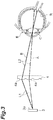
- FIG. 3 is a diagram illustrating the optical path extending from the optical scanning unit 3 to the eye E through the light diffusion unit 4.
- the optical scanning unit 3, the light diffusion unit 4, and the eye E are illustrated on one straight line and the optical system 11 is not illustrated.
- the laser light L1 reflected by the optical scanning unit 3 is incident to a pair of light diffusion channels 4a and 4a adjacent to each other (specifically, the light diffusion channels are adjacent to each other in the horizontal scanning direction and the vertical scanning direction of the laser light L1) arbitrarily selected from among the plurality of light diffusion channels 4a, a part of the light L2 diffused by one light diffusion channel 4a is incident to the eye E through the optical path A and a part of the light L2 diffused by the other light diffusion channel 4a is incident to the eye E through the optical path B. Then, the light L2 incident to the eye E is condensed on a retina R by a lens C.
- the condensing size of the laser light L1 in the light diffusion unit 4 is set to be equal to or smaller than the arrangement pitch of the plurality of light diffusion channels 4a (the "distance between the centers of the light diffusion channels 4a which are adjacent to each other (which are adjacent to each other at least in the scanning direction of the laser light L1)" when viewed from a direction perpendicular to a plane where the plurality of light diffusion channels 4a are arranged in two dimensions), luminance unevenness does not occur on the displayed image.
- the light diffusion unit 4 is configured so as to satisfy P ⁇ (4 ⁇ L)/( ⁇ M) when the wavelength of the laser light L1 (the maximum wavelength among the center wavelengths of the laser lights L1 emitted from the light emitting portions) is denoted by ⁇ , the effective opening diameter of the optical scanning unit 3 (the diameter of the mirror 3a) is denoted by M, the distance from the optical scanning unit 3 to the light diffusion unit 4 (the length of the optical path extending from the optical scanning unit 3 to the light diffusion unit 4) is denoted by L, and the arrangement pitch of the plurality of light diffusion channels 4a is denoted by P.
- the arrangement pitch of the light diffusion channels 4a is set so as to satisfy P ⁇ (4 ⁇ L)/( ⁇ M). Accordingly, the condensing size of the laser light L1 in the light diffusion unit 4 is set to be equal to or smaller than the arrangement pitch of the light diffusion channel 4a.
- the distance (: L) from the optical scanning unit 3 to the light diffusion unit 4 is desirably small and the effective opening diameter (: M) of the optical scanning unit 3 is desirably large.
- the tilting range of the mirror 3a needs to be increased in order to secure the scan range of the laser light L1 with respect to the light diffusion unit 4.
- the mirror 3a increases in size when the effective opening diameter (: M) of the optical scanning unit 3 is large, it is difficult to fast and stably tilt the mirror 3a.
- the MEMS mirror is used as the optical scanning unit 3
- the light diffusion unit 4 is configured so as to satisfy P ⁇ (4 ⁇ E)/( ⁇ M) + L ⁇ /M on the assumption that the laser light L1 is diffracted in the optical scanning unit 3.
- the arrangement pitch of the light diffusion channels 4a is set so as to satisfy P ⁇ (4 ⁇ E)/( ⁇ M) + L ⁇ /M.
- the arrangement pitch of the light diffusion channels 4a may be set so as to satisfy P ⁇ (4 ⁇ L)/( ⁇ M).
- the light diffusion unit 4 is configured so as to satisfy P ⁇ (4 ⁇ L)/( ⁇ M) + 2Ltan(2tan 11 (M/(2 ⁇ )))) in the scanning-type display system 10 and further the scanning-type display device 1.
- the arrangement pitch of the light diffusion channels 4a is set so as to satisfy P ⁇ (4 ⁇ L)/( ⁇ M) + 2Ltan(2tan -1 (M/(2 ⁇ ))).
- the "light is geometrically condensed as one point on the primary image surface (the light diffusion unit 4) when the mirror surface is a flat surface" and the “distortion of the mirror surface is a spherical shape expressed by the curvature radius ⁇ and is uniform in the entire area of the mirror surface" (in fact, the distortion of the mirror surface may not have a spherical shape and may not be uniform in the entire area).
- the optical path of the laser light L1 is geometrically considered in a cross-section including the center of the curvature radius ⁇ and the center of the mirror surface.
- the condensing size of the laser light L1 in the light diffusion unit 4 can be set to be equal to or smaller than the arrangement pitch of the light diffusion channels 4a.
- the scanning-type display device 1 it is possible to suppress an occurrence of luminance unevenness on a displayed image.
- the light diffusion unit 4 is configured so as to satisfy P ⁇ (4 ⁇ E)/( ⁇ M) + L ⁇ /M. Accordingly, since the condensing size of the laser light L1 in the light diffusion unit 4 can be set to be equal to or smaller than the arrangement pitch of the light diffusion channels 4a even when the laser light L1 is diffracted in the optical scanning unit 3, it is possible to suppress an occurrence of luminance unevenness on a displayed image.
- the optical scanning unit 3 is an MEMS mirror. Accordingly, it is possible to realize the high-speed and high-accuracy scanning of the laser light L1 with respect to the light diffusion unit 4.
- the light diffusion unit 4 is configured so as to satisfy P ⁇ (4 ⁇ L)/( ⁇ M) + 2Ltan(2tan -1 (M/(2 ⁇ ))) when the curvature radius of the mirror surface is denoted by ⁇ . Accordingly, since the condensing size of the laser light L1 in the light diffusion unit 4 can be set to be equal to or smaller than the arrangement pitch of the light diffusion channels 4a even when the mirror surface of the mirror 3a of the optical scanning unit 3 is distorted, it is possible to suppress an occurrence of luminance unevenness on a displayed image.
- the light diffusion unit 4 is a transmissive microlens array. Accordingly, it is possible to reliably and easily realize the diffusion of the laser light L1 by the plurality of light diffusion channels 4a arranged in two dimensions.
- the light source 2 is not limited to the laser diode (semiconductor laser) as long as coherent light (laser light) can be emitted therefrom and may be a surface emitting laser, a super luminescent diode (SLD), or the like.
- the optical scanning unit 3 is not limited to the MEMS mirror as long as the laser light can be scanned and may be a galvano mirror or the like.
- the light diffusion unit 4 is not limited to one which transmits and diffuses the laser light and may be one which reflects and diffuses the laser light.
- the light diffusion unit 4 is not limited to the transmissive microlens array as long as the plurality of light diffusion channels 4a which are arranged in two dimensions are provided and may be a reflective microlens array, a micro mirror array, a diffraction grating, a fiber optic plate, or the like.
- the light incident surface of the light diffusion unit 4 may be formed as a flat surface and the light emission surface of the light diffusion unit 4 may be formed as a plurality of convex surfaces corresponding to the plurality of microlenses.
- a plurality of concave surfaces may be formed instead of the plurality of convex surfaces so as to correspond to the plurality of microlenses.
- the light diffusion unit 4 may be configured so that the arrangement pitch of the light diffusion channels 4a becomes a value set on the basis of P ⁇ (4 ⁇ L)/( ⁇ M). For example, the light diffusion unit 4 may be configured so that the arrangement pitch of the light diffusion channel 4a satisfies P ⁇ (4 ⁇ E)/( ⁇ M) ⁇ 20 ⁇ m. The light diffusion unit 4 may be configured so that the arrangement pitch of the light diffusion channels 4a becomes a value set on the basis of P ⁇ (4 ⁇ E)/( ⁇ M) + L ⁇ /M. For example, the light diffusion unit 4 may be configured so that the arrangement pitch of the light diffusion channels 4a satisfies P ⁇ (4 ⁇ E)/( ⁇ M) + L ⁇ /M ⁇ 20 ⁇ m.
- the light diffusion unit 4 may be configured so that the arrangement pitch of the light diffusion channels 4a becomes a value set on the basis of P ⁇ (4 ⁇ E)/( ⁇ M) + 2Ltan(2tan -1 (M/(2 ⁇ ))).
- the light diffusion unit 4 may be configured so that the arrangement pitch of the light diffusion channels 4a satisfies P ⁇ (4 ⁇ E)/( ⁇ M) + 2Ltan(2tan -1 (M/(2 ⁇ ))) ⁇ 20 ⁇ m. That is, there is no need to satisfy a condition that P ⁇ (4 ⁇ E)/( ⁇ M) in all light diffusion channels 4a.
- the arrangement pitch of the plurality of light diffusion channels 4a needs not constant and may be, for example, random.
- the scanning-type display system 10 may not include the optical system 11 disposed at the subsequent stage of the light diffusion unit 4. Also in this case, it is possible to suppress an occurrence of luminance unevenness on a displayed image.
- the above-described scanning-type display device 1 is not limited to the in-vehicle type and can be used in various situations such as a helmet built-in type and glasses type.
- 1 scanning-type display device, 2 ... light source, 3 ... optical scanning unit, 4 ... light diffusion unit, 4a ... light diffusion channel, 6 ... condensing unit, 10 ... scanning-type display system, 11 ... optical system, L1 ... laser light
Landscapes
- Physics & Mathematics (AREA)
- General Physics & Mathematics (AREA)
- Optics & Photonics (AREA)
- Engineering & Computer Science (AREA)
- Mechanical Engineering (AREA)
- Chemical & Material Sciences (AREA)
- Combustion & Propulsion (AREA)
- Transportation (AREA)
- Mechanical Optical Scanning Systems (AREA)
- Mechanical Light Control Or Optical Switches (AREA)
- Fittings On The Vehicle Exterior For Carrying Loads, And Devices For Holding Or Mounting Articles (AREA)
- Instrument Panels (AREA)
Abstract
Description
- The present disclosure relates to a scanning-type display device and a scanning-type display system.
- There is known a scanning-type display device including a light source which emits projection-display laser light, an optical scanning unit which uses the laser light emitted from the light source in scanning, and a light diffusion unit which diffuses the laser light scanned by the optical scanning unit (for example, see Patent Literature 1). As the light diffusion unit, for example, an optical element including a plurality of light diffusion channels arranged in two dimensions such as a transmissive microlens array is used.
- Patent Literature 1: Japanese Unexamined Patent Publication No.
2016-133700 - In the above-described scanning-type display device, there is a case in which luminance unevenness (including irregular luminance unevenness (speckle) and regular luminance unevenness) occurs on a displayed image since the laser light is coherent light.
- An object of the present disclosure is to provide a scanning-type display device and a scanning-type display system capable of suppressing an occurrence of luminance unevenness on a displayed image.
- A scanning-type display device according to an aspect of the present disclosure includes: a light source which emits projection-display laser light; a condensing unit which condenses the laser light emitted from the light source; an optical scanning unit which uses the laser light passing through the condensing unit in scanning; and a light diffusion unit which includes a plurality of light diffusion channels arranged in two dimensions and diffuses the laser light scanned by the optical scanning unit, in which when a wavelength of the laser light is denoted by λ, an effective opening diameter of the optical scanning unit is denoted by M, a distance from the optical scanning unit to the light diffusion unit is denoted by L, and an arrangement pitch of the plurality of light diffusion channels is denoted by P, the light diffusion unit is configured so that the arrangement pitch becomes a value set on the basis of P ≥ (4λL)/(πM).
- According to the scanning-type display device, the condensing size of the laser light in the light diffusion unit can be set to be equal to or smaller than the arrangement pitch of the light diffusion channel. Thus, according to the scanning-type display device, it is possible to suppress an occurrence of luminance unevenness on a displayed image.
- In the scanning-type display device of an aspect of the present disclosure, the light diffusion unit may be configured so that the arrangement pitch becomes a value set on the basis of P ≥ (4λE)/(πM) + Lλ/M. Accordingly, since the condensing size of the laser light in the light diffusion unit can be set to be equal to or smaller than the arrangement pitch of the light diffusion channel even when the laser light is diffracted in the optical scanning unit, it is possible to suppress an occurrence of luminance unevenness on a displayed image.
- In the scanning-type display device of an aspect of the present disclosure, the optical scanning unit may be an MEMS mirror. Accordingly, it is possible to realize the high-speed and high-accuracy scanning of the laser light with respect to the light diffusion unit.
- In the scanning-type display device of an aspect of the present disclosure, when a curvature radius of a mirror surface of the MEMS mirror is denoted by φ, the light diffusion unit may be configured so that the arrangement pitch becomes a value set on the basis of P ≥ (4λE)/(πM) + 2Ltan(2tan-1(M/(2φ)))). Accordingly, since the condensing size of the laser light in the light diffusion unit can be set to be equal to or smaller than the arrangement pitch of the light diffusion channel even when the mirror surface of the MEMS mirror is distorted, it is possible to suppress an occurrence of luminance unevenness on a displayed image.
- In the scanning-type display device of an aspect of the present disclosure, the light diffusion unit may be a transmissive microlens array. Accordingly, it is possible to reliably and easily realize the diffusion of the laser light by the plurality of light diffusion channels arranged in two dimensions.
- A scanning-type display system according to an aspect of the present disclosure includes: a light source which emits projection-display laser light; a condensing unit which condenses the laser light emitted from the light source; an optical scanning unit which uses the laser light passing through the condensing unit in scanning; and a light diffusion unit which includes a plurality of light diffusion channels arranged in two dimensions and diffuses the laser light scanned by the optical scanning unit, in which when a wavelength of the laser light is denoted by λ, an effective opening diameter of the optical scanning unit is denoted by M, a distance from the optical scanning unit to the light diffusion unit is denoted by L, and an arrangement pitch of the plurality of light diffusion channels is denoted by P, the light diffusion unit is configured so that the arrangement pitch becomes a value set on the basis of P ≥ (4λL)/(πM).
- According to the scanning-type display system, the condensing size of the laser light in the light diffusion unit can be set to be equal to or smaller than the arrangement pitch of the light diffusion channels. Thus, according to the scanning-type display system, it is possible to suppress an occurrence of luminance unevenness on a displayed image.
- The scanning-type display system according to an aspect of the present disclosure may further include an optical system which is disposed at a subsequent stage of the light diffusion unit. Also in this case, it is possible to suppress an occurrence of luminance unevenness on a displayed image.
- According to the present disclosure, it is possible to provide a scanning-type display device and a scanning-type display system capable of suppressing an occurrence of luminance unevenness on a displayed image.
-
-
FIG. 1 is a configuration diagram of a scanning-type display system of an embodiment. -
FIG. 2 is a configuration diagram of a scanning-type display device of the scanning-type display system illustrated inFIG. 1 . -
FIG. 3 is a diagram illustrating an optical path extending from an optical scanning unit to an eye through a light diffusion unit. -
FIG. 4 is a diagram illustrating a light condensed state. -
FIG. 5 is a diagram illustrating a light diffraction phenomenon. - Hereinafter, an embodiment of the present disclosure will be described in detail with reference to the drawings. In the drawings, the same or corresponding components will be denoted by the same reference numerals and a redundant description thereof will be omitted.
- As illustrated in
FIG. 1 , a scanning-type display system 10 is, for example, a laser scanning-type projection display mounted on an automobile and displays (projection-displays) an image on afront glass 100 of the automobile. The scanning-type display system 10 includes a scanning-type display device 1 and anoptical system 11. Theoptical system 11 includes a plurality offlat mirrors concave mirror 11c, and thefront glass 100. Thefront glass 100 functions as an optical element at the last stage of theoptical system 11. Projection-display light L2 emitted from the scanning-type display device 1 is sequentially reflected by theflat mirror 11a, theflat mirror 11b, theconcave mirror 11c, and thefront glass 100 and is incident to an eye E of an observer. - As illustrated in
FIG. 2 , the scanning-type display device 1 includes alight source 2, acondensing unit 6, anoptical scanning unit 3, and alight diffusion unit 4. Thelight source 2 emits projection-display laser light L1. More specifically, thelight source 2 includes a plurality of light emitting portions. For example, the plurality of light emitting portions are respectively a red laser diode, a green laser diode, and a blue laser diode. Each light emitting portion emits the laser light L1 having a visible wavelength. The laser light L1 emitted from each light emitting portion is incident to thecondensing unit 6. Thecondensing unit 6 condenses the laser light L1 emitted from each light emitting portion. Thecondensing unit 6 is, for example, a condensing lens. The laser lights L1 emitted from the light emitting portions are combined by, for example, a dichroic mirror while the laser lights travel from thecondensing unit 6 to theoptical scanning unit 3. - The
optical scanning unit 3 uses the laser light L1 (the combined laser light L1) passing through thecondensing unit 6 in scanning. More specifically, theoptical scanning unit 3 is an MEMS mirror which reflects the laser light L1 passing through thecondensing unit 6, and uses the laser light L1 in scanning. The MEMS mirror is a drive mirror which is manufactured according to a Micro Electro Mechanical Systems (MEMS) technique and examples of the drive type include an electromagnetic drive type, an electrostatic drive type, a piezoelectric drive type, a thermal drive type, and the like. Theoptical scanning unit 3 includes aflat mirror 3a. Themirror 3a is tiltable about two orthogonal axes and is tilted fast at a resonant frequency in the rotation about one axis. Theoptical scanning unit 3 which is the MEMS mirror scans thelight diffusion unit 4 with the laser light L1. - The
light diffusion unit 4 includes a plurality oflight diffusion channels 4a which are arranged in two dimensions and diffuses the laser light L1 scanned by theoptical scanning unit 3. More specifically, thelight diffusion unit 4 is a transmissive microlens array. That is, thelight diffusion unit 4 transmits and diffuses the laser light L1 scanned by theoptical scanning unit 3. Thelight diffusion channel 4a is each of, for example, a plurality of microlenses arranged in a matrix shape. The light forming an image in the laser light L1 diffused by thelight diffusion unit 4 is incident to theoptical system 11 disposed at the subsequent stage of thelight diffusion unit 4 as the projection-display light L2 (seeFIG. 1 ). The light incident surface of thelight diffusion unit 4 includes a plurality of convex surfaces corresponding to the plurality of microlenses. Meanwhile, the light emission surface of thelight diffusion unit 4 is a flat surface. - The scanning-
type display device 1 with the above-described configuration is operated as below by a control unit (not illustrated). First, the control unit starts the output of each light emitting portion of thelight source 2 when receiving a projection-display start input signal. Accordingly, the laser light L1 is emitted from thelight source 2. Almost simultaneously, the control unit starts the operation of theoptical scanning unit 3. Accordingly, in theoptical scanning unit 3, the tilting of themirror 3a is started and the laser light L1 emitted from thelight source 2 and passing through the condensingunit 6 is scanned with respect to thelight diffusion unit 4. At this time, the control unit changes the ratio of the laser light L1 emitted from each light emitting portion of thelight source 2 in response to the scan position of the laser light L1 in thelight diffusion unit 4. Accordingly, the projection-display light L2 (that is, the light forming an image in the laser light L1 diffused by the light diffusion unit 4) is sequentially reflected by theflat mirror 11a, theflat mirror 11b, theconcave mirror 11c, and thefront glass 100 and is incident to the eye E of the observer. - Here, a principle that luminance unevenness (including irregular luminance unevenness (speckle) and regular luminance unevenness) occurs on the displayed image will be described.
FIG. 3 is a diagram illustrating the optical path extending from theoptical scanning unit 3 to the eye E through thelight diffusion unit 4. For convenience of description, inFIG. 3 , theoptical scanning unit 3, thelight diffusion unit 4, and the eye E are illustrated on one straight line and theoptical system 11 is not illustrated. - As illustrated in
FIG. 3 , when the laser light L1 reflected by theoptical scanning unit 3 is incident to a pair oflight diffusion channels light diffusion channels 4a, a part of the light L2 diffused by onelight diffusion channel 4a is incident to the eye E through the optical path A and a part of the light L2 diffused by the otherlight diffusion channel 4a is incident to the eye E through the optical path B. Then, the light L2 incident to the eye E is condensed on a retina R by a lens C. At this time, since an interference occurs when the light L2 incident to the eye E through the optical path A and the light L2 incident to the eye E through the optical path B overlap each other on the retina R, there is a possibility that luminance unevenness may occur on the displayed image. Thus, when the condensing size of the laser light L1 in thelight diffusion unit 4 is set to be equal to or smaller than the arrangement pitch of the plurality oflight diffusion channels 4a (the "distance between the centers of thelight diffusion channels 4a which are adjacent to each other (which are adjacent to each other at least in the scanning direction of the laser light L1)" when viewed from a direction perpendicular to a plane where the plurality oflight diffusion channels 4a are arranged in two dimensions), luminance unevenness does not occur on the displayed image. - From the above-described knowledge, in the scanning-
type display system 10 and further the scanning-type display device 1, thelight diffusion unit 4 is configured so as to satisfy P ≥ (4λL)/(πM) when the wavelength of the laser light L1 (the maximum wavelength among the center wavelengths of the laser lights L1 emitted from the light emitting portions) is denoted by λ, the effective opening diameter of the optical scanning unit 3 (the diameter of themirror 3a) is denoted by M, the distance from theoptical scanning unit 3 to the light diffusion unit 4 (the length of the optical path extending from theoptical scanning unit 3 to the light diffusion unit 4) is denoted by L, and the arrangement pitch of the plurality oflight diffusion channels 4a is denoted by P. Specifically, the arrangement pitch of thelight diffusion channels 4a is set so as to satisfy P ≥ (4λL)/(πM). Accordingly, the condensing size of the laser light L1 in thelight diffusion unit 4 is set to be equal to or smaller than the arrangement pitch of thelight diffusion channel 4a. - The reason is as below. As illustrated in
FIG. 4 , if the laser light is condensed by the condensing lens, 2ω = (4λF)/(πD) is satisfied when the wavelength of the laser light is denoted by λ, the spot diameter at the condensing position is denoted by 2ω, the focal length of the condensing lens is denoted by F, and the aperture diameter of the condensing lens is denoted by D. This equation shows that the spot diameter at the condensing position depends on NA on the image side (an angle in which the laser light is condensed at the condensing position). As NA increases, the spot diameter at the condensing position decreases. NA is determined by the diameter of the laser light in the condensing lens and the focal length of the condensing lens. Since F/D in the above-described equation indicates the "angle in which the laser light is condensed at the condensing position", it is understood that D = M and F = L on the assumption that the "spot diameter of the laser light L1 in themirror 3a of theoptical scanning unit 3" = the "effective opening diameter of theoptical scanning unit 3" by a similar relationship. Thus, it is found that the condensing size of the laser light L1 in thelight diffusion unit 4 is equal to or smaller than the arrangement pitch of thelight diffusion channel 4a when the arrangement pitch of thelight diffusion channel 4a is set so as to satisfy P ≥ (4λL)/(πM). - Since the resolution increases as the condensing size (: (4λL)/(πM)) of the laser light L1 in the
light diffusion unit 4 decreases, the occurrence of the interference can be suppressed. Regarding this point, the distance (: L) from theoptical scanning unit 3 to thelight diffusion unit 4 is desirably small and the effective opening diameter (: M) of theoptical scanning unit 3 is desirably large. However, when the distance (: L) from theoptical scanning unit 3 to thelight diffusion unit 4 is decreased, the tilting range of themirror 3a needs to be increased in order to secure the scan range of the laser light L1 with respect to thelight diffusion unit 4. Further, since themirror 3a increases in size when the effective opening diameter (: M) of theoptical scanning unit 3 is large, it is difficult to fast and stably tilt themirror 3a. When the MEMS mirror is used as theoptical scanning unit 3, it is particularly important to set the arrangement pitch of thelight diffusion channels 4a so as to satisfy P ≥ (4λE)/(πM) in consideration of the distance (: L) from theoptical scanning unit 3 to thelight diffusion unit 4 and the effective opening diameter (: M) of theoptical scanning unit 3 since there is such a limitation. - In order to secure the utilization efficiency of the laser light L1, a relationship of the "spot diameter of the laser light L1 in the
mirror 3a of theoptical scanning unit 3" = the "effective opening diameter of theoptical scanning unit 3" is desirable. However, there is a case in which themirror 3a functions as an aperture in fact. In this case, the laser light L1 is diffracted when the laser light L1 is reflected by themirror 3a. As illustrated inFIG. 5 , the diffraction spread width S of the aperture is expressed by S = Lλ/D when the wavelength of the laser light is denoted by λ, the effective opening diameter of the aperture is denoted by D, and the distance from the aperture to the condensing position is denoted by L (here, it is assumed that the first-order diffracted light significantly affects). Thus, in the scanning-type display system 10 and further the scanning-type display device 1, thelight diffusion unit 4 is configured so as to satisfy P ≥ (4λE)/(πM) + Lλ/M on the assumption that the laser light L1 is diffracted in theoptical scanning unit 3. Specifically, the arrangement pitch of thelight diffusion channels 4a is set so as to satisfy P ≥ (4λE)/(πM) + Lλ/M. When themirror 3a does not function as the aperture (that is, the "spot diameter of the laser light L1 in themirror 3a of theoptical scanning unit 3" < the "effective opening diameter of theoptical scanning unit 3"), the arrangement pitch of thelight diffusion channels 4a may be set so as to satisfy P ≥ (4λL)/(πM). - In the
optical scanning unit 3, there is a case in which the mirror surface of themirror 3a is distorted. The spread radius E of the laser light L1 due to the distortion of the mirror surface (the spread radius of the condensing size of the laser light L1 in the light diffusion unit 4) E is expressed by E = Ltan(2tan-1(M/(2φ))) when the distortion of the mirror surface is approximated to a sphere and its curvature radius is φ. Thus, when the mirror surface of themirror 3a of theoptical scanning unit 3 is distorted, thelight diffusion unit 4 is configured so as to satisfy P ≥ (4λL)/(πM) + 2Ltan(2tan11(M/(2φ)))) in the scanning-type display system 10 and further the scanning-type display device 1. Specifically, the arrangement pitch of thelight diffusion channels 4a is set so as to satisfy P ≥ (4λL)/(πM) + 2Ltan(2tan-1(M/(2φ))). - The reason why this equation is satisfied is as below. First, It is assumed that the "light is geometrically condensed as one point on the primary image surface (the light diffusion unit 4) when the mirror surface is a flat surface" and the "distortion of the mirror surface is a spherical shape expressed by the curvature radius φ and is uniform in the entire area of the mirror surface" (in fact, the distortion of the mirror surface may not have a spherical shape and may not be uniform in the entire area). The optical path of the laser light L1 is geometrically considered in a cross-section including the center of the curvature radius φ and the center of the mirror surface. When an angle formed by a "line connecting the outer edge of the mirror surface and the center of the curvature radius φ" and a "line connecting the center of the mirror surface and the center of the curvature radius φ" is denoted by θ, θ = tan-1(M/(2φ)) is satisfied when M << φ. By a similar relationship, an angle formed by a line connecting the mirror outermost edge points and a line perpendicular to the mirror distortion curvature center of the mirror distortion circle at the mirror outermost edge point is θ. The reflection angle of the laser light L1 which is reflected by the outer edge of the mirror surface deviates by 2θ due to the distortion of the mirror surface as compared with a case in which the mirror surface is a flat surface. The deviation amount E from the ideal condensing point on the primary image surface (the light diffusion unit 4) separated by the distance L is expressed by E = Ltan(2θ). Since the deviation amount E corresponds to the spread radius of the laser light L1 from an ideal condensed state, the spread radius E of the laser light L1 due to the distortion of the mirror surface is expressed by E = Ltan(2tan-1(M/(2))).
- As described above, according to the scanning-type display device 1 (and the scanning-type display system 10), the condensing size of the laser light L1 in the
light diffusion unit 4 can be set to be equal to or smaller than the arrangement pitch of thelight diffusion channels 4a. Thus, according to the scanning-type display device 1, it is possible to suppress an occurrence of luminance unevenness on a displayed image. - In the scanning-
type display device 1, thelight diffusion unit 4 is configured so as to satisfy P ≥ (4λE)/(πM) + Lλ/M. Accordingly, since the condensing size of the laser light L1 in thelight diffusion unit 4 can be set to be equal to or smaller than the arrangement pitch of thelight diffusion channels 4a even when the laser light L1 is diffracted in theoptical scanning unit 3, it is possible to suppress an occurrence of luminance unevenness on a displayed image. - In the scanning-
type display device 1, theoptical scanning unit 3 is an MEMS mirror. Accordingly, it is possible to realize the high-speed and high-accuracy scanning of the laser light L1 with respect to thelight diffusion unit 4. - In the scanning-
type display device 1, when the mirror surface of themirror 3a of theoptical scanning unit 3 is distorted, thelight diffusion unit 4 is configured so as to satisfy P ≥ (4λL)/(πM) + 2Ltan(2tan-1(M/(2φ))) when the curvature radius of the mirror surface is denoted by φ. Accordingly, since the condensing size of the laser light L1 in thelight diffusion unit 4 can be set to be equal to or smaller than the arrangement pitch of thelight diffusion channels 4a even when the mirror surface of themirror 3a of theoptical scanning unit 3 is distorted, it is possible to suppress an occurrence of luminance unevenness on a displayed image. - In the scanning-
type display device 1, thelight diffusion unit 4 is a transmissive microlens array. Accordingly, it is possible to reliably and easily realize the diffusion of the laser light L1 by the plurality oflight diffusion channels 4a arranged in two dimensions. - Although the embodiment of the present disclosure has been described above, the present disclosure is not limited to the above-described embodiment.
- For example, the
light source 2 is not limited to the laser diode (semiconductor laser) as long as coherent light (laser light) can be emitted therefrom and may be a surface emitting laser, a super luminescent diode (SLD), or the like. Theoptical scanning unit 3 is not limited to the MEMS mirror as long as the laser light can be scanned and may be a galvano mirror or the like. Thelight diffusion unit 4 is not limited to one which transmits and diffuses the laser light and may be one which reflects and diffuses the laser light. That is, thelight diffusion unit 4 is not limited to the transmissive microlens array as long as the plurality oflight diffusion channels 4a which are arranged in two dimensions are provided and may be a reflective microlens array, a micro mirror array, a diffraction grating, a fiber optic plate, or the like. When thelight diffusion unit 4 is the transmissive microlens array, the light incident surface of thelight diffusion unit 4 may be formed as a flat surface and the light emission surface of thelight diffusion unit 4 may be formed as a plurality of convex surfaces corresponding to the plurality of microlenses. A plurality of concave surfaces may be formed instead of the plurality of convex surfaces so as to correspond to the plurality of microlenses. - The
light diffusion unit 4 may be configured so that the arrangement pitch of thelight diffusion channels 4a becomes a value set on the basis of P ≥ (4λL)/(πM). For example, thelight diffusion unit 4 may be configured so that the arrangement pitch of thelight diffusion channel 4a satisfies P ≥ (4λE)/(πM) ± 20 µm. Thelight diffusion unit 4 may be configured so that the arrangement pitch of thelight diffusion channels 4a becomes a value set on the basis of P ≥ (4λE)/(πM) + Lλ/M. For example, thelight diffusion unit 4 may be configured so that the arrangement pitch of thelight diffusion channels 4a satisfies P ≥ (4λE)/(πM) + Lλ/M ± 20 µm. Thelight diffusion unit 4 may be configured so that the arrangement pitch of thelight diffusion channels 4a becomes a value set on the basis of P ≥ (4λE)/(πM) + 2Ltan(2tan-1(M/(2φ))). For example, thelight diffusion unit 4 may be configured so that the arrangement pitch of thelight diffusion channels 4a satisfies P ≥ (4λE)/(πM) + 2Ltan(2tan-1(M/(2φ))) ± 20 µm. That is, there is no need to satisfy a condition that P ≥ (4λE)/(πM) in alllight diffusion channels 4a. The same applies to a condition that P ≥ (4λE)/(πM) + Lλ/M and a condition that P ≥ (4λE)/(πM) + 2Ltan(2tan-1(M/(2φ))). The arrangement pitch of the plurality oflight diffusion channels 4a needs not constant and may be, for example, random. - The scanning-
type display system 10 may not include theoptical system 11 disposed at the subsequent stage of thelight diffusion unit 4. Also in this case, it is possible to suppress an occurrence of luminance unevenness on a displayed image. - The above-described scanning-
type display device 1 is not limited to the in-vehicle type and can be used in various situations such as a helmet built-in type and glasses type. - 1 ... scanning-type display device, 2 ... light source, 3 ... optical scanning unit, 4 ... light diffusion unit, 4a ... light diffusion channel, 6 ... condensing unit, 10 ... scanning-type display system, 11 ... optical system, L1 ... laser light
Claims (7)
- A scanning-type display device comprising:a light source which emits projection-display laser light;a condensing unit which condenses the laser light emitted from the light source;an optical scanning unit which uses the laser light passing through the condensing unit in scanning; anda light diffusion unit which includes a plurality of light diffusion channels arranged in two dimensions and diffuses the laser light scanned by the optical scanning unit,wherein when a wavelength of the laser light is denoted by λ, an effective opening diameter of the optical scanning unit is denoted by M, a distance from the optical scanning unit to the light diffusion unit is denoted by L, and an arrangement pitch of the plurality of light diffusion channels is denoted by P, the light diffusion unit is configured so that the arrangement pitch becomes a value set on the basis of P ≥ (4λL)/(πM).
- The scanning-type display device according to claim 1,
wherein the light diffusion unit is configured so that the arrangement pitch becomes a value set on the basis of P ≥ (4λE)/(πM) + Lλ/M. - The scanning-type display device according to claim 1 or 2,
wherein the optical scanning unit is an MEMS mirror. - The scanning-type display device according to claim 3,
wherein when a curvature radius of a mirror surface of the MEMS mirror is denoted by φ, the light diffusion unit is configured so that the arrangement pitch becomes a value set on the basis of P ≥ (4λE)/(πM) + 2Ltan(2tan-1(M/(2φ))). - The scanning-type display device according to any one of claims 1 to 4,
wherein the light diffusion unit is a transmissive microlens array. - A scanning-type display system comprising:a light source which emits projection-display laser light;a condensing unit which condenses the laser light emitted from the light source;an optical scanning unit which uses the laser light passing through the condensing unit in scanning; anda light diffusion unit which includes a plurality of light diffusion channels arranged in two dimensions and diffuses the laser light scanned by the optical scanning unit,wherein when a wavelength of the laser light is denoted by λ, an effective opening diameter of the optical scanning unit is denoted by M, a distance from the optical scanning unit to the light diffusion unit is denoted by L, and an arrangement pitch of the plurality of light diffusion channels is denoted by P, the light diffusion unit is configured so that the arrangement pitch becomes a value set on the basis of P ≥ (4λL)/(πM).
- The scanning-type display system according to claim 6, further comprising:
an optical system which is disposed at a subsequent stage of the light diffusion unit.
Applications Claiming Priority (2)
| Application Number | Priority Date | Filing Date | Title |
|---|---|---|---|
| JP2017116329A JP6535702B2 (en) | 2017-06-13 | 2017-06-13 | Scanning display device and scanning display system |
| PCT/JP2018/022262 WO2018230512A1 (en) | 2017-06-13 | 2018-06-11 | Scanning-type display device and scanning-type display system |
Publications (2)
| Publication Number | Publication Date |
|---|---|
| EP3640706A1 true EP3640706A1 (en) | 2020-04-22 |
| EP3640706A4 EP3640706A4 (en) | 2021-03-17 |
Family
ID=64660071
Family Applications (1)
| Application Number | Title | Priority Date | Filing Date |
|---|---|---|---|
| EP18818002.0A Pending EP3640706A4 (en) | 2017-06-13 | 2018-06-11 | SCAN DISPLAY DEVICE AND SCAN DISPLAY SYSTEM |
Country Status (7)
| Country | Link |
|---|---|
| US (1) | US11353716B2 (en) |
| EP (1) | EP3640706A4 (en) |
| JP (1) | JP6535702B2 (en) |
| KR (1) | KR102744249B1 (en) |
| CN (1) | CN110741305B (en) |
| TW (1) | TWI794244B (en) |
| WO (1) | WO2018230512A1 (en) |
Families Citing this family (5)
| Publication number | Priority date | Publication date | Assignee | Title |
|---|---|---|---|---|
| JP6535702B2 (en) | 2017-06-13 | 2019-06-26 | 浜松ホトニクス株式会社 | Scanning display device and scanning display system |
| JP7163868B2 (en) * | 2019-05-17 | 2022-11-01 | 株式会社デンソー | virtual image display |
| JP6608557B2 (en) * | 2019-06-03 | 2019-11-20 | 浜松ホトニクス株式会社 | Scanning display device and scanning display system |
| TWI723660B (en) * | 2019-09-09 | 2021-04-01 | 英錡科技股份有限公司 | Laser projection system, wearable image projection device and method for improving laser projection image |
| CN113853545A (en) * | 2020-03-31 | 2021-12-28 | 华为技术有限公司 | A device and head-up display for detecting excursion of diffuser film |
Family Cites Families (25)
| Publication number | Priority date | Publication date | Assignee | Title |
|---|---|---|---|---|
| JP2002014297A (en) | 2000-06-29 | 2002-01-18 | Miyota Kk | Galvano mirror |
| US7791810B2 (en) * | 2007-12-21 | 2010-09-07 | Microvision, Inc. | Scanned beam display having high uniformity and diminished coherent artifacts |
| KR101527120B1 (en) | 2010-08-17 | 2015-06-08 | 삼성전자주식회사 | Communication method of terminal and access point in an active mode for txop power saving of multiuser |
| JP2012108397A (en) | 2010-11-19 | 2012-06-07 | Nippon Seiki Co Ltd | Display device |
| JP5344069B2 (en) * | 2011-08-29 | 2013-11-20 | 株式会社デンソー | Head-up display device |
| JP2013101294A (en) * | 2011-09-28 | 2013-05-23 | Hitachi Media Electoronics Co Ltd | Scanning type projection device and scanning type image display apparatus |
| TWI443375B (en) | 2011-10-19 | 2014-07-01 | Univ Nat Central | One - dimensional scanning type pupil projection display device |
| JP2013205649A (en) | 2012-03-28 | 2013-10-07 | Toshiba Corp | Display device |
| JP5900445B2 (en) * | 2013-02-06 | 2016-04-06 | 株式会社デンソー | Head-up display device |
| US10598925B2 (en) * | 2013-05-10 | 2020-03-24 | North Inc. | Projection device |
| JP6323743B2 (en) | 2013-12-13 | 2018-05-16 | 大日本印刷株式会社 | Optical scanning device, illumination device, projection device, and optical element |
| JP6315240B2 (en) | 2014-02-03 | 2018-04-25 | 株式会社リコー | Image display device, moving body, and lens array |
| JP2015225218A (en) * | 2014-05-28 | 2015-12-14 | パイオニア株式会社 | Image display device |
| JP6172400B2 (en) * | 2014-09-03 | 2017-08-02 | 三菱電機株式会社 | Image display device |
| WO2016034247A1 (en) | 2014-09-05 | 2016-03-10 | Lemoptix Sa | An image projector and optical assembly |
| JP6481298B2 (en) * | 2014-09-10 | 2019-03-13 | 日本精機株式会社 | Head-up display device |
| JP6489841B2 (en) | 2015-01-21 | 2019-03-27 | パイオニア株式会社 | Head-up display |
| JP2016151681A (en) | 2015-02-18 | 2016-08-22 | 株式会社Jvcケンウッド | Mems optical scanner |
| JP6448472B2 (en) | 2015-05-29 | 2019-01-09 | アルプス電気株式会社 | Display device |
| EP3104212A3 (en) * | 2015-06-11 | 2017-02-22 | Ricoh Company, Ltd. | Microlens array, image display apparatus, and optical scanner |
| JP6579485B2 (en) * | 2015-06-11 | 2019-09-25 | 株式会社リコー | Optical scanning device, image display device, and object device |
| JP6146680B2 (en) * | 2015-06-22 | 2017-06-14 | 大日本印刷株式会社 | Lighting device |
| JP2017078830A (en) | 2015-10-22 | 2017-04-27 | 矢崎総業株式会社 | Transmissive screen for scanning projector, scanning projector system |
| JP6586635B2 (en) * | 2015-11-25 | 2019-10-09 | パナソニックIpマネジメント株式会社 | Image display device |
| JP6535702B2 (en) | 2017-06-13 | 2019-06-26 | 浜松ホトニクス株式会社 | Scanning display device and scanning display system |
-
2017
- 2017-06-13 JP JP2017116329A patent/JP6535702B2/en active Active
-
2018
- 2018-06-11 US US16/621,391 patent/US11353716B2/en active Active
- 2018-06-11 CN CN201880038988.7A patent/CN110741305B/en active Active
- 2018-06-11 WO PCT/JP2018/022262 patent/WO2018230512A1/en not_active Ceased
- 2018-06-11 EP EP18818002.0A patent/EP3640706A4/en active Pending
- 2018-06-11 KR KR1020197032811A patent/KR102744249B1/en active Active
- 2018-06-13 TW TW107120268A patent/TWI794244B/en not_active IP Right Cessation
Also Published As
| Publication number | Publication date |
|---|---|
| CN110741305A (en) | 2020-01-31 |
| TW201903474A (en) | 2019-01-16 |
| KR20200016210A (en) | 2020-02-14 |
| CN110741305B (en) | 2022-09-23 |
| JP6535702B2 (en) | 2019-06-26 |
| WO2018230512A1 (en) | 2018-12-20 |
| KR102744249B1 (en) | 2024-12-19 |
| EP3640706A4 (en) | 2021-03-17 |
| TWI794244B (en) | 2023-03-01 |
| US20200257130A1 (en) | 2020-08-13 |
| US11353716B2 (en) | 2022-06-07 |
| JP2019002983A (en) | 2019-01-10 |
Similar Documents
| Publication | Publication Date | Title |
|---|---|---|
| US11353716B2 (en) | Scanning-type display device and scanning-type display system | |
| US10502972B2 (en) | Image display device and mobile object | |
| US9247221B2 (en) | Scanning type projector | |
| US20170115553A1 (en) | Scanning projector transmissive screen, and scanning projector system | |
| JP2019045858A (en) | Backlight unit and head-up display device | |
| JP6402854B2 (en) | Transmission screen and head-up display device using the same | |
| US10527923B2 (en) | Scanning projector transmissive screen, and scanning projector system | |
| JP7098594B2 (en) | Scanning display device and scanning display system | |
| US11204497B2 (en) | Scanning-type display device, scanning-type display system, and method for manufacturing light-diffusing part | |
| JP6608557B2 (en) | Scanning display device and scanning display system | |
| JP4639691B2 (en) | Optical scanning device and image display device | |
| WO2004042450A1 (en) | Lighting system and compact projection system | |
| JP2019066757A (en) | Image display device |
Legal Events
| Date | Code | Title | Description |
|---|---|---|---|
| STAA | Information on the status of an ep patent application or granted ep patent |
Free format text: STATUS: THE INTERNATIONAL PUBLICATION HAS BEEN MADE |
|
| PUAI | Public reference made under article 153(3) epc to a published international application that has entered the european phase |
Free format text: ORIGINAL CODE: 0009012 |
|
| STAA | Information on the status of an ep patent application or granted ep patent |
Free format text: STATUS: REQUEST FOR EXAMINATION WAS MADE |
|
| 17P | Request for examination filed |
Effective date: 20200102 |
|
| AK | Designated contracting states |
Kind code of ref document: A1 Designated state(s): AL AT BE BG CH CY CZ DE DK EE ES FI FR GB GR HR HU IE IS IT LI LT LU LV MC MK MT NL NO PL PT RO RS SE SI SK SM TR |
|
| AX | Request for extension of the european patent |
Extension state: BA ME |
|
| DAV | Request for validation of the european patent (deleted) | ||
| DAX | Request for extension of the european patent (deleted) | ||
| A4 | Supplementary search report drawn up and despatched |
Effective date: 20210215 |
|
| RIC1 | Information provided on ipc code assigned before grant |
Ipc: B60R 11/02 20060101ALI20210209BHEP Ipc: G02B 26/10 20060101AFI20210209BHEP Ipc: G02B 27/01 20060101ALI20210209BHEP Ipc: B60K 35/00 20060101ALI20210209BHEP |
|
| STAA | Information on the status of an ep patent application or granted ep patent |
Free format text: STATUS: EXAMINATION IS IN PROGRESS |
|
| 17Q | First examination report despatched |
Effective date: 20230126 |