EP3640675A1 - Estimating angle of a human target using millimeter-wave radar - Google Patents
Estimating angle of a human target using millimeter-wave radar Download PDFInfo
- Publication number
- EP3640675A1 EP3640675A1 EP19203217.5A EP19203217A EP3640675A1 EP 3640675 A1 EP3640675 A1 EP 3640675A1 EP 19203217 A EP19203217 A EP 19203217A EP 3640675 A1 EP3640675 A1 EP 3640675A1
- Authority
- EP
- European Patent Office
- Prior art keywords
- range
- doppler
- angle
- arrival
- target
- Prior art date
- Legal status (The legal status is an assumption and is not a legal conclusion. Google has not performed a legal analysis and makes no representation as to the accuracy of the status listed.)
- Granted
Links
Images




Classifications
-
- G—PHYSICS
- G01—MEASURING; TESTING
- G01S—RADIO DIRECTION-FINDING; RADIO NAVIGATION; DETERMINING DISTANCE OR VELOCITY BY USE OF RADIO WAVES; LOCATING OR PRESENCE-DETECTING BY USE OF THE REFLECTION OR RERADIATION OF RADIO WAVES; ANALOGOUS ARRANGEMENTS USING OTHER WAVES
- G01S13/00—Systems using the reflection or reradiation of radio waves, e.g. radar systems; Analogous systems using reflection or reradiation of waves whose nature or wavelength is irrelevant or unspecified
- G01S13/02—Systems using reflection of radio waves, e.g. primary radar systems; Analogous systems
- G01S13/06—Systems determining position data of a target
- G01S13/08—Systems for measuring distance only
- G01S13/10—Systems for measuring distance only using transmission of interrupted, pulse modulated waves
- G01S13/26—Systems for measuring distance only using transmission of interrupted, pulse modulated waves wherein the transmitted pulses use a frequency- or phase-modulated carrier wave
-
- G—PHYSICS
- G01—MEASURING; TESTING
- G01S—RADIO DIRECTION-FINDING; RADIO NAVIGATION; DETERMINING DISTANCE OR VELOCITY BY USE OF RADIO WAVES; LOCATING OR PRESENCE-DETECTING BY USE OF THE REFLECTION OR RERADIATION OF RADIO WAVES; ANALOGOUS ARRANGEMENTS USING OTHER WAVES
- G01S13/00—Systems using the reflection or reradiation of radio waves, e.g. radar systems; Analogous systems using reflection or reradiation of waves whose nature or wavelength is irrelevant or unspecified
- G01S13/02—Systems using reflection of radio waves, e.g. primary radar systems; Analogous systems
- G01S13/50—Systems of measurement based on relative movement of target
- G01S13/58—Velocity or trajectory determination systems; Sense-of-movement determination systems
- G01S13/583—Velocity or trajectory determination systems; Sense-of-movement determination systems using transmission of continuous unmodulated waves, amplitude-, frequency-, or phase-modulated waves and based upon the Doppler effect resulting from movement of targets
- G01S13/584—Velocity or trajectory determination systems; Sense-of-movement determination systems using transmission of continuous unmodulated waves, amplitude-, frequency-, or phase-modulated waves and based upon the Doppler effect resulting from movement of targets adapted for simultaneous range and velocity measurements
-
- G—PHYSICS
- G01—MEASURING; TESTING
- G01S—RADIO DIRECTION-FINDING; RADIO NAVIGATION; DETERMINING DISTANCE OR VELOCITY BY USE OF RADIO WAVES; LOCATING OR PRESENCE-DETECTING BY USE OF THE REFLECTION OR RERADIATION OF RADIO WAVES; ANALOGOUS ARRANGEMENTS USING OTHER WAVES
- G01S13/00—Systems using the reflection or reradiation of radio waves, e.g. radar systems; Analogous systems using reflection or reradiation of waves whose nature or wavelength is irrelevant or unspecified
- G01S13/02—Systems using reflection of radio waves, e.g. primary radar systems; Analogous systems
- G01S13/06—Systems determining position data of a target
- G01S13/42—Simultaneous measurement of distance and other co-ordinates
- G01S13/44—Monopulse radar, i.e. simultaneous lobing
- G01S13/449—Combined with MTI or Doppler processing circuits
-
- A—HUMAN NECESSITIES
- A61—MEDICAL OR VETERINARY SCIENCE; HYGIENE
- A61B—DIAGNOSIS; SURGERY; IDENTIFICATION
- A61B5/00—Measuring for diagnostic purposes; Identification of persons
- A61B5/05—Detecting, measuring or recording for diagnosis by means of electric currents or magnetic fields; Measuring using microwaves or radio waves
- A61B5/0507—Detecting, measuring or recording for diagnosis by means of electric currents or magnetic fields; Measuring using microwaves or radio waves using microwaves or terahertz waves
-
- G—PHYSICS
- G01—MEASURING; TESTING
- G01S—RADIO DIRECTION-FINDING; RADIO NAVIGATION; DETERMINING DISTANCE OR VELOCITY BY USE OF RADIO WAVES; LOCATING OR PRESENCE-DETECTING BY USE OF THE REFLECTION OR RERADIATION OF RADIO WAVES; ANALOGOUS ARRANGEMENTS USING OTHER WAVES
- G01S13/00—Systems using the reflection or reradiation of radio waves, e.g. radar systems; Analogous systems using reflection or reradiation of waves whose nature or wavelength is irrelevant or unspecified
- G01S13/02—Systems using reflection of radio waves, e.g. primary radar systems; Analogous systems
- G01S13/06—Systems determining position data of a target
- G01S13/42—Simultaneous measurement of distance and other co-ordinates
- G01S13/44—Monopulse radar, i.e. simultaneous lobing
- G01S13/4454—Monopulse radar, i.e. simultaneous lobing phase comparisons monopulse, i.e. comparing the echo signals received by an interferometric antenna arrangement
-
- G—PHYSICS
- G01—MEASURING; TESTING
- G01S—RADIO DIRECTION-FINDING; RADIO NAVIGATION; DETERMINING DISTANCE OR VELOCITY BY USE OF RADIO WAVES; LOCATING OR PRESENCE-DETECTING BY USE OF THE REFLECTION OR RERADIATION OF RADIO WAVES; ANALOGOUS ARRANGEMENTS USING OTHER WAVES
- G01S13/00—Systems using the reflection or reradiation of radio waves, e.g. radar systems; Analogous systems using reflection or reradiation of waves whose nature or wavelength is irrelevant or unspecified
- G01S13/02—Systems using reflection of radio waves, e.g. primary radar systems; Analogous systems
- G01S13/50—Systems of measurement based on relative movement of target
- G01S13/505—Systems of measurement based on relative movement of target using Doppler effect for determining closest range to a target or corresponding time, e.g. miss-distance indicator
-
- G—PHYSICS
- G01—MEASURING; TESTING
- G01S—RADIO DIRECTION-FINDING; RADIO NAVIGATION; DETERMINING DISTANCE OR VELOCITY BY USE OF RADIO WAVES; LOCATING OR PRESENCE-DETECTING BY USE OF THE REFLECTION OR RERADIATION OF RADIO WAVES; ANALOGOUS ARRANGEMENTS USING OTHER WAVES
- G01S13/00—Systems using the reflection or reradiation of radio waves, e.g. radar systems; Analogous systems using reflection or reradiation of waves whose nature or wavelength is irrelevant or unspecified
- G01S13/02—Systems using reflection of radio waves, e.g. primary radar systems; Analogous systems
- G01S13/50—Systems of measurement based on relative movement of target
- G01S13/58—Velocity or trajectory determination systems; Sense-of-movement determination systems
- G01S13/581—Velocity or trajectory determination systems; Sense-of-movement determination systems using transmission of interrupted pulse modulated waves and based upon the Doppler effect resulting from movement of targets
-
- G—PHYSICS
- G01—MEASURING; TESTING
- G01S—RADIO DIRECTION-FINDING; RADIO NAVIGATION; DETERMINING DISTANCE OR VELOCITY BY USE OF RADIO WAVES; LOCATING OR PRESENCE-DETECTING BY USE OF THE REFLECTION OR RERADIATION OF RADIO WAVES; ANALOGOUS ARRANGEMENTS USING OTHER WAVES
- G01S13/00—Systems using the reflection or reradiation of radio waves, e.g. radar systems; Analogous systems using reflection or reradiation of waves whose nature or wavelength is irrelevant or unspecified
- G01S13/02—Systems using reflection of radio waves, e.g. primary radar systems; Analogous systems
- G01S13/50—Systems of measurement based on relative movement of target
- G01S13/58—Velocity or trajectory determination systems; Sense-of-movement determination systems
- G01S13/581—Velocity or trajectory determination systems; Sense-of-movement determination systems using transmission of interrupted pulse modulated waves and based upon the Doppler effect resulting from movement of targets
- G01S13/582—Velocity or trajectory determination systems; Sense-of-movement determination systems using transmission of interrupted pulse modulated waves and based upon the Doppler effect resulting from movement of targets adapted for simultaneous range and velocity measurements
-
- G—PHYSICS
- G01—MEASURING; TESTING
- G01S—RADIO DIRECTION-FINDING; RADIO NAVIGATION; DETERMINING DISTANCE OR VELOCITY BY USE OF RADIO WAVES; LOCATING OR PRESENCE-DETECTING BY USE OF THE REFLECTION OR RERADIATION OF RADIO WAVES; ANALOGOUS ARRANGEMENTS USING OTHER WAVES
- G01S13/00—Systems using the reflection or reradiation of radio waves, e.g. radar systems; Analogous systems using reflection or reradiation of waves whose nature or wavelength is irrelevant or unspecified
- G01S13/66—Radar-tracking systems; Analogous systems
- G01S13/72—Radar-tracking systems; Analogous systems for two-dimensional [2D] tracking, e.g. combination of angle and range tracking, track-while-scan radar
-
- G—PHYSICS
- G01—MEASURING; TESTING
- G01S—RADIO DIRECTION-FINDING; RADIO NAVIGATION; DETERMINING DISTANCE OR VELOCITY BY USE OF RADIO WAVES; LOCATING OR PRESENCE-DETECTING BY USE OF THE REFLECTION OR RERADIATION OF RADIO WAVES; ANALOGOUS ARRANGEMENTS USING OTHER WAVES
- G01S13/00—Systems using the reflection or reradiation of radio waves, e.g. radar systems; Analogous systems using reflection or reradiation of waves whose nature or wavelength is irrelevant or unspecified
- G01S13/66—Radar-tracking systems; Analogous systems
- G01S13/72—Radar-tracking systems; Analogous systems for two-dimensional [2D] tracking, e.g. combination of angle and range tracking, track-while-scan radar
- G01S13/723—Radar-tracking systems; Analogous systems for two-dimensional [2D] tracking, e.g. combination of angle and range tracking, track-while-scan radar by using numerical data
- G01S13/726—Multiple target tracking
-
- G—PHYSICS
- G01—MEASURING; TESTING
- G01S—RADIO DIRECTION-FINDING; RADIO NAVIGATION; DETERMINING DISTANCE OR VELOCITY BY USE OF RADIO WAVES; LOCATING OR PRESENCE-DETECTING BY USE OF THE REFLECTION OR RERADIATION OF RADIO WAVES; ANALOGOUS ARRANGEMENTS USING OTHER WAVES
- G01S13/00—Systems using the reflection or reradiation of radio waves, e.g. radar systems; Analogous systems using reflection or reradiation of waves whose nature or wavelength is irrelevant or unspecified
- G01S13/88—Radar or analogous systems specially adapted for specific applications
-
- G—PHYSICS
- G01—MEASURING; TESTING
- G01S—RADIO DIRECTION-FINDING; RADIO NAVIGATION; DETERMINING DISTANCE OR VELOCITY BY USE OF RADIO WAVES; LOCATING OR PRESENCE-DETECTING BY USE OF THE REFLECTION OR RERADIATION OF RADIO WAVES; ANALOGOUS ARRANGEMENTS USING OTHER WAVES
- G01S7/00—Details of systems according to groups G01S13/00, G01S15/00, G01S17/00
- G01S7/02—Details of systems according to groups G01S13/00, G01S15/00, G01S17/00 of systems according to group G01S13/00
- G01S7/41—Details of systems according to groups G01S13/00, G01S15/00, G01S17/00 of systems according to group G01S13/00 using analysis of echo signal for target characterisation; Target signature; Target cross-section
- G01S7/411—Identification of targets based on measurements of radar reflectivity
-
- G—PHYSICS
- G01—MEASURING; TESTING
- G01S—RADIO DIRECTION-FINDING; RADIO NAVIGATION; DETERMINING DISTANCE OR VELOCITY BY USE OF RADIO WAVES; LOCATING OR PRESENCE-DETECTING BY USE OF THE REFLECTION OR RERADIATION OF RADIO WAVES; ANALOGOUS ARRANGEMENTS USING OTHER WAVES
- G01S7/00—Details of systems according to groups G01S13/00, G01S15/00, G01S17/00
- G01S7/02—Details of systems according to groups G01S13/00, G01S15/00, G01S17/00 of systems according to group G01S13/00
- G01S7/41—Details of systems according to groups G01S13/00, G01S15/00, G01S17/00 of systems according to group G01S13/00 using analysis of echo signal for target characterisation; Target signature; Target cross-section
- G01S7/418—Theoretical aspects
-
- A—HUMAN NECESSITIES
- A61—MEDICAL OR VETERINARY SCIENCE; HYGIENE
- A61B—DIAGNOSIS; SURGERY; IDENTIFICATION
- A61B5/00—Measuring for diagnostic purposes; Identification of persons
- A61B5/08—Measuring devices for evaluating the respiratory organs
- A61B5/0816—Measuring devices for examining respiratory frequency
-
- A—HUMAN NECESSITIES
- A61—MEDICAL OR VETERINARY SCIENCE; HYGIENE
- A61B—DIAGNOSIS; SURGERY; IDENTIFICATION
- A61B5/00—Measuring for diagnostic purposes; Identification of persons
- A61B5/103—Measuring devices for testing the shape, pattern, colour, size or movement of the body or parts thereof, for diagnostic purposes
- A61B5/11—Measuring movement of the entire body or parts thereof, e.g. head or hand tremor or mobility of a limb
- A61B5/1113—Local tracking of patients, e.g. in a hospital or private home
-
- A—HUMAN NECESSITIES
- A61—MEDICAL OR VETERINARY SCIENCE; HYGIENE
- A61B—DIAGNOSIS; SURGERY; IDENTIFICATION
- A61B5/00—Measuring for diagnostic purposes; Identification of persons
- A61B5/103—Measuring devices for testing the shape, pattern, colour, size or movement of the body or parts thereof, for diagnostic purposes
- A61B5/11—Measuring movement of the entire body or parts thereof, e.g. head or hand tremor or mobility of a limb
- A61B5/113—Measuring movement of the entire body or parts thereof, e.g. head or hand tremor or mobility of a limb occurring during breathing
- A61B5/1135—Measuring movement of the entire body or parts thereof, e.g. head or hand tremor or mobility of a limb occurring during breathing by monitoring thoracic expansion
-
- A—HUMAN NECESSITIES
- A61—MEDICAL OR VETERINARY SCIENCE; HYGIENE
- A61B—DIAGNOSIS; SURGERY; IDENTIFICATION
- A61B5/00—Measuring for diagnostic purposes; Identification of persons
- A61B5/72—Signal processing specially adapted for physiological signals or for diagnostic purposes
- A61B5/7225—Details of analogue processing, e.g. isolation amplifier, gain or sensitivity adjustment, filtering, baseline or drift compensation
-
- A—HUMAN NECESSITIES
- A61—MEDICAL OR VETERINARY SCIENCE; HYGIENE
- A61B—DIAGNOSIS; SURGERY; IDENTIFICATION
- A61B5/00—Measuring for diagnostic purposes; Identification of persons
- A61B5/72—Signal processing specially adapted for physiological signals or for diagnostic purposes
- A61B5/7235—Details of waveform analysis
- A61B5/7253—Details of waveform analysis characterised by using transforms
- A61B5/7257—Details of waveform analysis characterised by using transforms using Fourier transforms
-
- G—PHYSICS
- G01—MEASURING; TESTING
- G01S—RADIO DIRECTION-FINDING; RADIO NAVIGATION; DETERMINING DISTANCE OR VELOCITY BY USE OF RADIO WAVES; LOCATING OR PRESENCE-DETECTING BY USE OF THE REFLECTION OR RERADIATION OF RADIO WAVES; ANALOGOUS ARRANGEMENTS USING OTHER WAVES
- G01S7/00—Details of systems according to groups G01S13/00, G01S15/00, G01S17/00
- G01S7/02—Details of systems according to groups G01S13/00, G01S15/00, G01S17/00 of systems according to group G01S13/00
- G01S7/28—Details of pulse systems
- G01S7/285—Receivers
- G01S7/288—Coherent receivers
- G01S7/2883—Coherent receivers using FFT processing
-
- G—PHYSICS
- G01—MEASURING; TESTING
- G01S—RADIO DIRECTION-FINDING; RADIO NAVIGATION; DETERMINING DISTANCE OR VELOCITY BY USE OF RADIO WAVES; LOCATING OR PRESENCE-DETECTING BY USE OF THE REFLECTION OR RERADIATION OF RADIO WAVES; ANALOGOUS ARRANGEMENTS USING OTHER WAVES
- G01S7/00—Details of systems according to groups G01S13/00, G01S15/00, G01S17/00
- G01S7/02—Details of systems according to groups G01S13/00, G01S15/00, G01S17/00 of systems according to group G01S13/00
- G01S7/35—Details of non-pulse systems
- G01S7/352—Receivers
- G01S7/356—Receivers involving particularities of FFT processing
Definitions
- the present invention relates generally to an electronic system and method, and, in particular embodiments, to estimating angle of human target using a millimeter-wave (mmWave) radar.
- mmWave millimeter-wave
- the distance between the radar and a target is determined by transmitting a frequency modulated signal, receiving a reflection of the frequency modulated signal (also referred to as the echo), and determining a distance based on a time delay and/or frequency difference between the transmission and reception of the frequency modulated signal.
- some radar systems include a transmit antenna to transmit the radio-frequency (RF) signal, and a receive antenna to receive the reflected RF signal, as well as the associated RF circuitry used to generate the transmitted signal and to receive the RF signal.
- multiple antennas may be used to implement directional beams using phased array techniques.
- a multiple-input and multiple-output (MIMO) configuration with multiple chipsets can be used to perform coherent and non-coherent signal processing as well.
- a method of estimating an angle of arrival of a radar signal reflected on a human target includes: receiving the reflected radar signal with first and second antennas of a millimeter-wave radar; transforming the reflected radar signal received with the first and second antennas to generate first and second range spectrum, respectively; generating a first range-Doppler map based on the first range spectrum; generating a second range-Doppler map based on the second range spectrum; determining or estimating a Doppler velocity based on the first range-Doppler map or the second range-Doppler map; macro-compensating the first range-Doppler map and the second range-Doppler map by selecting a peak in the first range-Doppler map or the second range-Doppler map based on the determined Doppler velocity; identifying an index of the first macro-compensated range-Doppler map corresponding to an identified target; estimating a phase difference based on the first and second macro-compensated range-Doppler maps and the identified
- a millimeter-wave radar includes: first and second receiving antennas configured to receive a reflected radar signal, and a controller.
- the controller is configured to: transform the reflected radar signal received with the first and second receiving antennas to generate first and second range spectrum, respectively; generate a first range-Doppler map based on the first range spectrum; generate a second range-Doppler map based on the second range spectrum; determine or estimate a Doppler velocity based on the first range-Doppler map or the second range-Doppler map; compensate the first range-Doppler map and the second range-Doppler map by selecting a peak in the first range-Doppler map or the second range-Doppler map based on the determined Doppler velocity; identify an index of the first macro-compensated range-Doppler map corresponding to an identified target; estimate a phase difference based on the first and second macro-compensated range-Doppler maps and the identified index; and estimate an angle of arrival of the reflected signal based on the phase difference
- a method of estimating an angle of arrival of a radar signal reflected on a human target includes: transmitting a radar signal towards the human target using a millimeter-wave radar, the transmitted radar signal including a sequence of pulses; receiving the reflected radar signal with first and second antennas of a millimeter-wave radar; determining a range of the human target based on the reflected signal; determining a Doppler velocity of the human target based on the reflected radar signal and the determined range of the human target; generating first and second compensated range-Doppler maps based on the reflected radar signal, the determined range of the human target, and the determined Doppler velocity; identifying an index of the first compensated range-Doppler map corresponding to an identified target; estimating a phase difference based on the first and second compensated range-Doppler maps and the identified index; and estimating the angle of arrival based on the phase difference.
- the present invention will be described with respect to embodiments in a specific context, a method of determining the angle of arrival of radar signals reflected from humans using a millimeter-wave radar having at least two receiving antennas and operating as a frequency-modulated continuous-wave (FMCW) radar.
- Embodiments of the present invention may be extended to other types of radars, such as pulsed radars.
- estimating the angle of arrival of a radar signal reflected in a human is improved by compensating for Doppler components before calculating the angle of arrival using a phase mono-pulse algorithm.
- the macro-Doppler component of a moving human is subtracted from a range-Doppler map before estimating the angle of arrival.
- Doppler components associated with vital signs e.g., breathing are compensated before estimating the angle of arrival.
- a millimeter-wave radar may be used to determine the angle of arrival of radar signals reflected in a human.
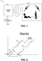
- Figure 1 shows radar system 100, according to an embodiment of the present invention.
- Radar system 100 includes millimeter-wave radar 102 and processor 104.
- millimeter-wave radar 102 transmits a plurality of radiation pulses 106, such as chirps, towards scene 108.
- the chirps are linear chirps (i.e., the instantaneous frequency of the chirp varies linearly with time).
- the transmitted radiation pulses 106 are reflected by objects in scene 108.
- the reflected radiation pulses (not shown in Figure 1 ), which are also referred to as the echo signal, are detected by millimeter-wave radar 102 and processed by processor 104 to, for example, determine the angle of arrival of the echo signal.
- the objects in scene 108 may include static humans, such as lying human 110, humans exhibiting low and infrequent motions, such as standing human 112, and moving humans, such as running or walking human 114 and 116.
- the objects in scene 108 may also include static objects, such as furniture and periodic movement equipment (not shown). Other objects may also be present in scene 108.
- Processor 104 analyses the echo data to determine the location of humans using signal processing techniques. For example, in some embodiments, a range FFT is used for estimating the range component of the location of a detected human (i.e., how far is the human from the millimeter-wave radar). The azimuth component of the location of the detected human may be determined using angle estimation techniques.
- a range FFT is used for estimating the range component of the location of a detected human (i.e., how far is the human from the millimeter-wave radar).
- the azimuth component of the location of the detected human may be determined using angle estimation techniques.
- Processor 104 may be implemented as a general purpose processor, controller or digital signal processor (DSP) that includes, for example, combinatorial circuits coupled to a memory.
- the DSP may be implemented with an ARM architecture, for example.
- processor 104 may be implemented as a custom application specific integrated circuit (ASIC).
- processor 104 includes a plurality of processors, each having one or more processing cores.
- processor 104 includes a single processor having one or more processing cores.
- decoder 302 using software running in a general purpose micro-controller or processor having, for example, a CPU coupled to a memory and implemented with an ARM or x86 architecture.
- Some embodiments may be implemented as a combination of hardware accelerator and software running on a DSP or general purpose micro-controller.
- Millimeter-wave radar 102 operates as a FMCW radar that includes a millimeter-wave radar sensor circuit, a transmitting antenna, and at least two receiving antennas. Millimeter-wave radar 102 transmits and receives signals in the 20 GHz to 122 GHz range. Alternatively, frequencies outside of this range, such as frequencies between 1 GHz and 20 GHz, or frequencies between 122 GHz, and 300 GHz, may also be used.
- the echo signals received by the receiving antennas of millimeter-wave radar 102 are filtered and amplified using band-pass filter (BPFs), low-pass filter (LPFs), mixers, low-noise amplifier (LNAs), and intermediate frequency (IF) amplifiers in ways known in the art.
- BPFs band-pass filter
- LPFs low-pass filter
- LNAs low-noise amplifier
- IF intermediate frequency amplifier
- the echo signals are then digitized using one or more analog-to-digital converters (ADCs) for further processing.
- ADCs analog-to-digital converters
- Angle estimation for determining the azimuth component of the location of static or moving targets (e.g., humans) using a millimeter-wave radar may be performed using a phase mono-pulse algorithm.
- Figure 2 illustrates an operation of an exemplary implementation of a phase mono-pulse technique for estimating the angle of arrival of incident signals.
- receiving antennas 206 and 208 of millimeter-wave radar 102 which are separated by a distance d , receive incident signals 202 and 204 after being reflected in objects in scene 108.
- Receiving antennas 206 and 208 receive incident signals 202 and 204 at different times based on the angle of arrival ⁇ . For example, when incident signal 204 arrives at receiving antenna 208, incident signal 202 is at a distance d 1 from receiving antenna 206.
- phase difference ⁇ ⁇ 2 ⁇ ⁇ ⁇ d ⁇ sin ⁇
- ⁇ is the wavelengths of incident signals 202 and 204
- d is the distance between receiving antennas 206 and 208
- Figure 3 illustrates a flow chart of embodiment method 300 of estimating the angle of arrival, according to an embodiment of the present invention.
- Method 300 may be implemented, for example, by millimeter-wave radar 102.
- the millimeter-wave radar transmits a sequence of pulses, such as FMCW chirps, towards a scene, such as scene 108.
- a positive ⁇ represents an up-chirp and a negative ⁇ represents a down-chirp.
- Receiver RX1 receives signal S RX using a respective receiving antenna, such as receiving antenna 206 during step 304.
- receiver RX2 receives signal S RX using a respective receiving antenna, such as receiving antenna 208 during step 314.
- Signal S RX includes the reflected pulses.
- range spectra are generated, e.g., using an FFT, in fast time, based on the reflected pulses received by receiver RX1 (e.g., using intermediate frequency signal S IF ). For example, in some embodiments, each received pulse is processed to generate a corresponding intermediate signal pulse, and an FFT is performed on each corresponding intermediate signal pulse to generate a corresponding spectrum. Terms that are independent of time t f appear as a phase offset in the frequency domain.
- Such peak may be associated with a target (i.e., a target present in the range R associated with the bin in which the peak is present).
- step 316 range spectra are generated, in fast time, based on the reflected pulses received by receiver RX2 in a similar manner as in step 306.
- range bins of the spectrum generated during step 306 are associated with targets (e.g., humans).
- targets are identified during step 308 using a peak searching algorithm that compares the value of each bin with a threshold.
- a peak f p is identified by scanning the range bin vector from, e.g., left to right, and by detecting a negative slope from adjacent bins.
- a peak f p is identified in bin 0 .
- range bins adjacent to the bin exhibiting a peak are also associated with a target to account for possible errors in the range bin identification (e.g., one bin before and one bin after the range bin exhibiting the peak, two bins before and two bins after the range bin exhibiting the peak, etc.). In some embodiments, therefore, a set of bins is used as an initial coarse estimate for range detection. In some embodiments, multiple targets are identified. Method 300 may also apply to multiple targets.
- range bins of the spectrum generated during step 316 are associated with targets (e.g., humans) during step 318. However, since the target range bins identified during step 308 are typically equal to the target range bins identified during step 318, some embodiments skip step 318.
- a range-Doppler map is generated using a Doppler FFT on the identified target range bins (step 308) of the range spectrum generated during step 306.
- a range-Doppler map is generated by performing an FFT, in slow time, for the range bins associated with the target in step 308. The range-Doppler map results in a map having an axis
- a peak at an index (x i ,y j ) of the range-Doppler map is associated with a target present at range R i and traveling with Doppler velocity v j , where range R i corresponds with bin i of the range bins, and Doppler velocity v j corresponds with bin j of the Doppler velocity bins.
- a range-Doppler map is generated using a Doppler FFT on the identified target range bins (step 308 or 318) of the range spectrum generated during step 316.
- a range-Doppler index is identified for each target based on the range-Doppler map generated during step 310.
- the range-Doppler indices are identified using a two-dimensional (2D) peak search algorithm.
- a range-Doppler index is identified during step 322 for each target based on the range-Doppler map generated during step 320.
- range-Doppler indices identified during step 312 are typically equal to range-Doppler indices identified during step 322, some embodiments may skip step 322.
- a phase difference between signals received by receivers RX1 and RX2 is determined for each identified target based on the range-Doppler maps (generated during steps 310 and 320) using the range-Doppler indices determined during steps 312 (and 322).
- the angle of arrival is estimated using a phase mono-pulse algorithm, such as by using Equation 2.
- the estimated angle of arrival is stored for further processing (e.g., for target location predictions or to improve the accuracy of future angle of arrival estimates).
- the accuracy of the estimated angle ⁇ depends on the accuracy of the phase difference ⁇ ⁇ .
- the phase difference ⁇ ⁇ may be affected, for example, by Doppler components of the target. For example, when M pulses are transmitted towards a static object, phase and amplitude of each of the corresponding M reflected pulses are substantially identical to each other. When the target object is moving (e.g., a moving human), the phase information of each of the M reflected pulses varies depending on the direction of movement, velocity, etc.
- the Doppler frequency f d may result in a change in amplitude and phase of intermediate frequency signal S IF over slow time.
- the macro-Doppler components associated with a moving human are estimated and subtracted from the range-Doppler map (steps 310 and 320) before extracting the phase difference (in step 324), thus compensating for effects of Doppler components in the estimation of angle of arrival ⁇ , thereby increasing the angle of arrival ⁇ accuracy.
- the macro-Doppler components associated with a moving human are subtracted from the range-Doppler map by extracting the peak from the I + jQ data from the range-Doppler map.
- Doppler components of the target may also affect range estimations (step 308).
- Figure 4 shows ambiguity function ⁇ of a conventional FMCW waveform.
- the error contribution of the Doppler components associated with the Doppler velocity v to range R is zero.
- the target Doppler velocity v is not zero (either positive or negative Doppler velocity v)
- the range uncertainty determined based on the ambiguity function ⁇ is ⁇ 2 range bins.
- range bins 23-27 are also considered when generating the range-Doppler map during step 310 (and 320).
- Method 300 is sensitive to SNR. For example, low SNR in the range spectrum generated in step 306 may result in failure to identify a target.
- SNR is improved by performing coherent integration of N received pulses (e.g., during step 306), where N is the total number of chirps in a frame.
- N is the total number of chirps in a frame.
- an ADC is used to sample the signal received by a receiver (e.g., in step 304).
- An FFT is performed on each pulse received in fast time (e.g., in step 306).
- N FFTs of consecutive pulses are added up coherently (i.e., range bin by range bin) before, e.g., step 308.
- the coherently integrated FFT has higher SNR than each individual FFT because uncorrelated noise of each individual FFT tends to cancel out when integrated while correlated information (e.g., the peak representing the range of the target) does not.
- correlated information e.g., the peak representing the range of the target
- N is equal to 16 or 32. Other number of pulses for coherent integration may also be used.
- low SNR in the range-Doppler map may result in an error in the estimated angle of arrival ⁇ .
- Figure 5 shows a graph of angle estimation error using a phase mono-pulse technique versus SNR of the range-Doppler map after Doppler velocity compensation.
- Performing angle estimation with low SNR may also result in the angle estimation at the edges of the filed-of-view (FoV) of the millimeter-wave radar to jump from one side to the other side of the FoV, meaning that the target may be estimated to be, e.g., at 25°, when the target is actually at -25°.
- FoV filed-of-view
- some embodiments estimate the angle of arrival ⁇ (step 326) based on the range-Doppler maps generated in steps 310 and 320 only if the SNR of the range-Doppler maps are above an SNR threshold (e.g., higher than 10 dB).
- the SNR threshold is based on the range threshold used to identify peaks during step 308. For example, in an embodiment, the range threshold for peak identification during step 306 is th 1 , and the SNR threshold for determining whether to estimate angle of arrival ⁇ is 1.2 ⁇ th 1 .
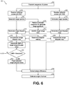
- Figure 6 illustrates a flow chart of embodiment method 600 of estimating the angle of arrival, according to an embodiment of the present invention.
- Method 600 may be implemented, for example, by millimeter-wave radar 102.
- the millimeter-wave radar transmits a sequence of pulses in a similar manner as in step 302.
- receivers RX1 and RX2 receive reflected pulses in a similar manner as in steps 304 and 314, respectively.
- Some embodiments use more than two antennas for determining angle of arrival.
- range spectra are generated on a frame of pulses received by receiver RX1 and RX2 in a similar manner as in steps 306 and 316, respectively.
- coherent integration of the range spectra of the frame is performed to generate an integrated spectrum.
- range bins of the integrated range spectrum are associated with targets in a similar manner as in step 308.
- the range bins are identified taking into account range uncertainty (e.g., based on the ambiguity function). In some embodiments, it is possible to identify multiple targets.
- range-Doppler maps are respectively generated based on respective range spectra (generated in steps 606 and 630) using the targets identified in step 610.
- the Doppler velocity of each identified target is determined based on the range-Doppler map generated in step 612 (and/or in step 632).
- the range-Doppler map (e.g., generated in step 612) is compensated for the corresponding Doppler velocity of each identified target.
- the range-Doppler map is, in effect, compensated for the Doppler component of the identified target.
- the range-Doppler map (e.g., generated in step 632) is compensated for the corresponding Doppler velocity of each identified target.
- the SNR for each target range-Doppler index (e.g., from step 616) is determined in step 618. If it is determined during step 620 that the SNR of a target range-Doppler index is sufficiently high (e.g., higher than 1.2 times the range threshold), such target range-Doppler index is used to extract phase difference during step 624. If it is determined that the SNR is low (e.g., lower than 1.2 times the range threshold), then, in some embodiments, the associated phase information is discarded and not used for estimating the angle of arrival, e.g., as described with respect to step 818.
- step 624 a phase difference between signals received by receivers RX1 and RX2 is determined for each identified target in a similar manner as in step 324.
- step 626 the angle of arrival is determined in a similar manner as in step 326.
- micro-Doppler components associated with vital signs of the static human target may cause a phase rotation of the signal at the range where the static human target is present, thereby affecting the accuracy of the estimated angle ⁇ .
- the respiratory rate of a static human may range from 12 to 20 breaths per minute (0.2 Hz - 0.4 Hz) and may have an associated displacement of the chest wall of up to around 7.5 mm.
- the phase rotation associated with Doppler components generated by vitals of the target human is compensated by aggregating the mean Doppler FFT data on the identified target range over a time sufficient to capture the frequency of the vital (e.g., 3.2 seconds for breathing).
- the vital frequency is estimated by performing a peak search on the generated Doppler FFT.
- the bin showing the vital frequency is used to determine the angle of arrival based on the signals received by receivers RX1 and RX2.
- Figure 7 illustrates a flow chart of embodiment method 700 of estimating the angle of arrival, according to an embodiment of the present invention.
- Method 700 may operate in a similar manner as method 600.
- Method 700 also compensate for Doppler components associated with vital signals of a static human. For example, during step 702, it is determined whether the target human is static or moving. If the target human is moving, method 700 proceeds in a similar manner as method 600.
- the zero-Doppler peak values of the compensated range-Doppler map are captured over a plurality of frames (step 703) in respective vectors (one per receiver) and an FFT of the vector is computed during step 704.
- an array is used to accumulate peaks over multiple frames during step 703.
- the zero-Doppler FFT vector is used to compensate the range-Doppler maps from steps 616 and 634 for micro-Doppler components, such as breathing, hand movements, etc., during step 705.
- the respective zero-Doppler vectors are based on the range-Doppler maps generated in steps 612 and 632 without compensating them in steps 616 and 634. Performing steps 703, 704, and 705 advantageously allows for compensating for low frequency Doppler velocities (e.g., lower than 1 Hz).
- each frame takes 200 ⁇ s
- 16 frames may be used during step 704, resulting in the utilization of 3.2 seconds of data.
- Different number of frames and frames with a different duration may be used.
- step 724 when the humans are moving, the phase difference is determined in a similar manner as in step 624. If the humans are static, however, the phase difference is based in the micro-Doppler compensated range-Doppler maps from step 705 (one for each receiver) instead of the compensated range-Doppler maps from steps 616 and 634.
- the angle of arrival is estimated in step 626 based on the phase difference determined in step 724.
- methods 300, 600 and 700 are performed continuously.
- target tracking and angle tracking is performed to improve the accuracy of the estimated angle of arrival.
- Figure 8 illustrates a flow chart of embodiment method 800 of estimating the angle of arrival, according to an embodiment of the present invention. The discussion that follows assumes that method 800 is implemented as part of method 600 (some steps have been omitted for clarity purposes). However, method 800 may be implemented with other methods of estimating the angle of arrival, such as methods 300, or 700, for example.
- Step 826 the angle of arrival is determined.
- Step 826 includes steps 802, 804, 806, 808, 810, 812, and 816. In some embodiments, one or more of steps 806, 808, 810, 812, and 816 are skipped.
- step 802 an initial angle of arrival is estimated using the phase mono-pulse algorithm based on the phase difference extracted in step 624 for each identified target.
- each identified target is associated with a tracked target (e.g., previously stored in memory) based on the range and Doppler velocity (estimated in step 616). For example, during step 804, the range and Doppler velocity of each identified target may be compared with historic tracks of previously identified targets (e.g., stored in memory). Each identified target, then, may be associated with a track in which the last reported range and Doppler velocity are closest to it.
- a new track is created.
- correlation between variations of identified targets are performed to determine if the identified target is a ghost human (e.g., a target suddenly appears in a location that would have required a human to move faster than humanly possible). If a target is identified as a ghost human, then no track is associated with such identified target. In some embodiments, static humans are not tracked (only tracked when the human moves).
- Tracks that are not associated with an identified target may be cancelled. Other tracking methods may be used.
- the difference in angle of arrival estimated in step 802 and the previous angle of arrival is determined during step 806. If the difference is greater that a threshold (which may be determined, for example, based on the velocity of a typical moving human), the angle of arrival is not updated. For example, in some embodiments, if the difference is greater that a threshold, the angle of arrival determined during step 802 is not used for tracking purposes, and not used for reporting the angle of arrival during step 826. For example, some embodiments may use a predicted angle of arrival (e.g., generated during step 810) instead of the estimated angle of arrival (estimated during step 802) for tracking purposes (e.g., storing in memory) and as an output of step 826.
- a threshold which may be determined, for example, based on the velocity of a typical moving human
- a sequence of Q angles of arrivals (where Q includes Q-1 previously stored angles of arrival and the currently estimated angle of arrival) is filtered using a median filter to remove outliers during step 808.
- a prediction of angle of arrival change for each identified target is generated based on an estimate of tangential velocity of each identified target (e.g., based on previously stored range and angle of arrival for the respective identified target).
- Weighting between the predicted angle of arrival and the estimated angle of arrival is performed during step 812. For example, if an identified target has an SNR higher than an SNR threshold (see step 620) and the difference in angle of arrival estimated in step 802 and the previous angle of arrival is lower than an angle threshold (see step 806), then the weights used for the predicted angle (step 810) and the measured angled (802, 808) may be 0.5 for each.
- the weights used for the predicted angle (step 810) and the measured angled (802, 808) may be 1 and 0, respective (in other words, no weight is assigned to the estimated angle of arrival and 100% weight is assigned to the predicted angle of arrival.
- the weights applied to the predicted angle of arrival and the estimated angle of arrival may be predetermined. In other embodiments, the weights applied to the predicted angle of arrival and the estimated angle of arrival are dynamically generated using, e.g., a Kalman filter or Bayesian techniques, or according to a predetermined rule(s).
- the angle of arrival is smoothened using a moving average.
- Advantages of some embodiments include the capability of accurately estimating angle of arrival of radar signals reflected in moving or static humans in low SNR regimes. Additional advantages include the improvement of SNR of reflected radar signals, thereby improving the estimate of angle of arrival. By improving the SNR, the update rate (i.e., the times in which the angle of arrival is updated - see step 620, for example) is increased. In some embodiments, by improving the estimation of the angle of arrival and by increasing the rate in which the angle of arrival is estimated, the estimation of the location of a human (including the azimuth component), and the tracking of the human in space are also improved.
- Some embodiments, such as methods 300, 600, 700 and 800, may be used in various applications Figures 9-12 show non-limiting examples of applications of methods 300, 600, 700, and 800.
- Figure 9 shows room 900 having sound system 902, according to an embodiment of the present invention.
- millimeter-wave radar 102 estimates the azimuth component of humans by estimating the angle of arrival using, e.g., method 300, 600, 700, or 800.
- Controller 904 receives (e.g., wirelessly) the azimuth components of moving (114) or static (112) humans and causes sound system 902 to direct sound to the direction of humans (e.g., using beamforming techniques known in the art).
- FIG 10 shows hotel hallway 1000, according to an embodiment of the present invention.
- millimeter-wave radar 102 (which may be installed in a ceiling of hotel hallway 1000, for example) controls one or more hotel room functions based on tracking the angle of arrival of humans moving in hotel hallway 1000. For example, in some embodiments, millimeter-wave radar 102 determines whether humans are inside each hotel room based on estimating and tracking the angle of arrival of humans as they move through hotel hallway 1000. Based on the detected human movement, millimeter-wave-radar 102 determines if humans have entered or exited each hotel room, and counts the number of humans entering or exiting each hotel room. Controller 1002 controls lights and/or HVAC of each hotel room based on the number of humans in each hotel room (e.g., controller 1002 turns off lights and HVAC in a hotel room having no humans).
- FIG 11 shows automatic gates 1102 and 1104, according to an embodiment of the present invention.
- Automatic doors 1102 and 1104 include respective millimeter-wave radars 102 1 and 102 2 .
- millimeter-wave radars 102 1 and 102 2 causes automatic doors 1102 and 1104 to open or close based on humans movement.
- Millimeter-wave radars 102 1 and 102 2 also count the number of humans crossing in each direction by tracking the angle of arrival of human targets as they move through respective fields-of view 1106 and 1108 of millimeter-wave radars 1102 and 1104.
- millimeter-wave radars 102 1 and 102 2 are installed in automatic gates 1102 and 1104 and have the capability of detecting angle of arrival in a horizontal direction (i.e., parallel to the floor).
- Figure 12 shows another embodiment that operates in a similar manner as the embodiment of Figure 11 .
- the embodiment of Figure 12 has millimeter-wave radars 102 1 and 102 2 installed at a ceiling and having the capability of detecting angle of arrival in a vertical direction (i.e., perpendicular to the floor).
Landscapes
- Engineering & Computer Science (AREA)
- Radar, Positioning & Navigation (AREA)
- Remote Sensing (AREA)
- Physics & Mathematics (AREA)
- Computer Networks & Wireless Communication (AREA)
- General Physics & Mathematics (AREA)
- Health & Medical Sciences (AREA)
- Life Sciences & Earth Sciences (AREA)
- Heart & Thoracic Surgery (AREA)
- Animal Behavior & Ethology (AREA)
- Electromagnetism (AREA)
- Biophysics (AREA)
- Pathology (AREA)
- Biomedical Technology (AREA)
- Radiology & Medical Imaging (AREA)
- Molecular Biology (AREA)
- Nuclear Medicine, Radiotherapy & Molecular Imaging (AREA)
- Surgery (AREA)
- Medical Informatics (AREA)
- General Health & Medical Sciences (AREA)
- Public Health (AREA)
- Veterinary Medicine (AREA)
- Radar Systems Or Details Thereof (AREA)
Abstract
Description
- The present invention relates generally to an electronic system and method, and, in particular embodiments, to estimating angle of human target using a millimeter-wave (mmWave) radar.
- Applications in the millimeter-wave frequency regime have gained significant interest in the past few years due to the rapid advancement in low cost semiconductor technologies, such as silicon germanium (SiGe) and fine geometry complementary metal-oxide semiconductor (CMOS) processes. Availability of high-speed bipolar and metal-oxide semiconductor (MOS) transistors has led to a growing demand for integrated circuits for millimeter-wave applications at 24 GHz, 60 GHz, 77 GHz, and 80 GHz and also beyond 100 GHz. Such applications include, for example, automotive radar systems and multi-gigabit communication systems.
- In some radar systems, the distance between the radar and a target is determined by transmitting a frequency modulated signal, receiving a reflection of the frequency modulated signal (also referred to as the echo), and determining a distance based on a time delay and/or frequency difference between the transmission and reception of the frequency modulated signal. Accordingly, some radar systems include a transmit antenna to transmit the radio-frequency (RF) signal, and a receive antenna to receive the reflected RF signal, as well as the associated RF circuitry used to generate the transmitted signal and to receive the RF signal. In some cases, multiple antennas may be used to implement directional beams using phased array techniques. A multiple-input and multiple-output (MIMO) configuration with multiple chipsets can be used to perform coherent and non-coherent signal processing as well.
- There may be a demand for providing an improved concept for a method of estimating an angle of arrival of a radar signal reflected on a human target and a millimeter-wave radar.
- Such a demand may be satisfied by the subject matter of any of the claims.
- In accordance with an embodiment, a method of estimating an angle of arrival of a radar signal reflected on a human target includes: receiving the reflected radar signal with first and second antennas of a millimeter-wave radar; transforming the reflected radar signal received with the first and second antennas to generate first and second range spectrum, respectively; generating a first range-Doppler map based on the first range spectrum; generating a second range-Doppler map based on the second range spectrum; determining or estimating a Doppler velocity based on the first range-Doppler map or the second range-Doppler map; macro-compensating the first range-Doppler map and the second range-Doppler map by selecting a peak in the first range-Doppler map or the second range-Doppler map based on the determined Doppler velocity; identifying an index of the first macro-compensated range-Doppler map corresponding to an identified target; estimating a phase difference based on the first and second macro-compensated range-Doppler maps and the identified index; and estimating the angle of arrival based on the phase difference.
- In accordance with an embodiment, a millimeter-wave radar includes: first and second receiving antennas configured to receive a reflected radar signal, and a controller. The controller is configured to: transform the reflected radar signal received with the first and second receiving antennas to generate first and second range spectrum, respectively; generate a first range-Doppler map based on the first range spectrum; generate a second range-Doppler map based on the second range spectrum; determine or estimate a Doppler velocity based on the first range-Doppler map or the second range-Doppler map; compensate the first range-Doppler map and the second range-Doppler map by selecting a peak in the first range-Doppler map or the second range-Doppler map based on the determined Doppler velocity; identify an index of the first macro-compensated range-Doppler map corresponding to an identified target; estimate a phase difference based on the first and second macro-compensated range-Doppler maps and the identified index; and estimate an angle of arrival of the reflected signal based on the phase difference.
- In accordance with an embodiment, a method of estimating an angle of arrival of a radar signal reflected on a human target includes: transmitting a radar signal towards the human target using a millimeter-wave radar, the transmitted radar signal including a sequence of pulses; receiving the reflected radar signal with first and second antennas of a millimeter-wave radar; determining a range of the human target based on the reflected signal; determining a Doppler velocity of the human target based on the reflected radar signal and the determined range of the human target; generating first and second compensated range-Doppler maps based on the reflected radar signal, the determined range of the human target, and the determined Doppler velocity; identifying an index of the first compensated range-Doppler map corresponding to an identified target; estimating a phase difference based on the first and second compensated range-Doppler maps and the identified index; and estimating the angle of arrival based on the phase difference.
- For a more complete understanding of the present invention, and the advantages thereof, reference is now made to the following descriptions taken in conjunction with the accompanying drawings, in which:
-
Figure 1 shows a radar system, according to an embodiment of the present invention; -
Figure 2 illustrates an operation of an exemplary implementation of a phase mono-pulse technique for estimating the angle of arrival of incident signals; -
Figure 3 illustrates a flow chart of an embodiment method of estimating the angle of arrival, according to an embodiment of the present invention; -
Figure 4 shows an ambiguity function of a conventional FMCW waveform; -
Figure 5 shows a graph of angle estimation error using a phase mono-pulse technique versus signal-to-noise ratio (SNR); -
Figures 6-8 illustrate flow charts of embodiment methods of estimating the angle of arrival, according to embodiments of the present invention; and -
Figures 9-12 show non-limiting examples of applications of the embodiment methods ofFigures 3 and6-8 , according to embodiments of the present invention. - Corresponding numerals and symbols in different figures generally refer to corresponding parts unless otherwise indicated. The figures are drawn to clearly illustrate the relevant aspects of the preferred embodiments and are not necessarily drawn to scale.
- The making and using of the embodiments disclosed are discussed in detail below. It should be appreciated, however, that the present invention provides many applicable inventive concepts that can be embodied in a wide variety of specific contexts. The specific embodiments discussed are merely illustrative of specific ways to make and use the invention, and do not limit the scope of the invention.
- The description below illustrates the various specific details to provide an in-depth understanding of several example embodiments according to the description. The embodiments may be obtained without one or more of the specific details, or with other methods, components, materials and the like. In other cases, known structures, materials or operations are not shown or described in detail so as not to obscure the different aspects of the embodiments. References to "an embodiment" in this description indicate that a particular configuration, structure or feature described in relation to the embodiment is included in at least one embodiment. Consequently, phrases such as "in one embodiment" that may appear at different points of the present description do not necessarily refer exactly to the same embodiment. Furthermore, specific formations, structures or features may be combined in any appropriate manner in one or more embodiments.
- The present invention will be described with respect to embodiments in a specific context, a method of determining the angle of arrival of radar signals reflected from humans using a millimeter-wave radar having at least two receiving antennas and operating as a frequency-modulated continuous-wave (FMCW) radar. Embodiments of the present invention may be extended to other types of radars, such as pulsed radars.
- In an embodiment of the present invention, estimating the angle of arrival of a radar signal reflected in a human is improved by compensating for Doppler components before calculating the angle of arrival using a phase mono-pulse algorithm. The macro-Doppler component of a moving human is subtracted from a range-Doppler map before estimating the angle of arrival. For static humans, Doppler components associated with vital signs (e.g., breathing) are compensated before estimating the angle of arrival.
- A millimeter-wave radar may be used to determine the angle of arrival of radar signals reflected in a human. For example,
Figure 1 showsradar system 100, according to an embodiment of the present invention.Radar system 100 includes millimeter-wave radar 102 andprocessor 104. - During normal operation, millimeter-
wave radar 102 transmits a plurality ofradiation pulses 106, such as chirps, towardsscene 108. In some embodiments the chirps are linear chirps (i.e., the instantaneous frequency of the chirp varies linearly with time). - The transmitted
radiation pulses 106 are reflected by objects inscene 108. The reflected radiation pulses (not shown inFigure 1 ), which are also referred to as the echo signal, are detected by millimeter-wave radar 102 and processed byprocessor 104 to, for example, determine the angle of arrival of the echo signal. - The objects in
scene 108 may include static humans, such as lying human 110, humans exhibiting low and infrequent motions, such as standing human 112, and moving humans, such as running or walkinghuman scene 108 may also include static objects, such as furniture and periodic movement equipment (not shown). Other objects may also be present inscene 108. -
Processor 104 analyses the echo data to determine the location of humans using signal processing techniques. For example, in some embodiments, a range FFT is used for estimating the range component of the location of a detected human (i.e., how far is the human from the millimeter-wave radar). The azimuth component of the location of the detected human may be determined using angle estimation techniques. -
Processor 104 may be implemented as a general purpose processor, controller or digital signal processor (DSP) that includes, for example, combinatorial circuits coupled to a memory. In some embodiments, the DSP may be implemented with an ARM architecture, for example. In some embodiments,processor 104 may be implemented as a custom application specific integrated circuit (ASIC). In some embodiments,processor 104 includes a plurality of processors, each having one or more processing cores. In other embodiments,processor 104 includes a single processor having one or more processing cores. Other implementations are also possible. For example, some embodiments may implementdecoder 302 using software running in a general purpose micro-controller or processor having, for example, a CPU coupled to a memory and implemented with an ARM or x86 architecture. Some embodiments may be implemented as a combination of hardware accelerator and software running on a DSP or general purpose micro-controller. - Millimeter-
wave radar 102 operates as a FMCW radar that includes a millimeter-wave radar sensor circuit, a transmitting antenna, and at least two receiving antennas. Millimeter-wave radar 102 transmits and receives signals in the 20 GHz to 122 GHz range. Alternatively, frequencies outside of this range, such as frequencies between 1 GHz and 20 GHz, or frequencies between 122 GHz, and 300 GHz, may also be used. - In some embodiments, the echo signals received by the receiving antennas of millimeter-
wave radar 102 are filtered and amplified using band-pass filter (BPFs), low-pass filter (LPFs), mixers, low-noise amplifier (LNAs), and intermediate frequency (IF) amplifiers in ways known in the art. The echo signals are then digitized using one or more analog-to-digital converters (ADCs) for further processing. Other implementations are also possible. - Angle estimation for determining the azimuth component of the location of static or moving targets (e.g., humans) using a millimeter-wave radar may be performed using a phase mono-pulse algorithm. For example,
Figure 2 illustrates an operation of an exemplary implementation of a phase mono-pulse technique for estimating the angle of arrival of incident signals. - During normal operation, receiving
antennas wave radar 102, which are separated by a distance d, receiveincident signals scene 108. Receivingantennas incident signals incident signal 204 arrives at receivingantenna 208,incident signal 202 is at a distance d 1 from receivingantenna 206. Such phenomenon may be translated as a phase difference Δφ, which may be given by
antennas 
-
Figure 3 illustrates a flow chart ofembodiment method 300 of estimating the angle of arrival, according to an embodiment of the present invention.Method 300 may be implemented, for example, by millimeter-wave radar 102. - During
step 302, the millimeter-wave radar transmits a sequence of pulses, such as FMCW chirps, towards a scene, such asscene 108. The FMCW chirp signal STX may be modelled as:

- Receiver RX1 receives signal SRX using a respective receiving antenna, such as receiving
antenna 206 duringstep 304. Similarly, receiver RX2 receives signal SRX using a respective receiving antenna, such as receivingantenna 208 duringstep 314. Signal SRX includes the reflected pulses. - An object in the field of view of the millimeter-wave radar located at base distance R may induce a round trip delay τ (between transmitted signal STX and received signal SRX ) given by:


- During
step 306, range spectra are generated, e.g., using an FFT, in fast time, based on the reflected pulses received by receiver RX1 (e.g., using intermediate frequency signal SIF ). For example, in some embodiments, each received pulse is processed to generate a corresponding intermediate signal pulse, and an FFT is performed on each corresponding intermediate signal pulse to generate a corresponding spectrum. Terms that are independent of time tf appear as a phase offset in the frequency domain. An FFT along the fast time of the intermediate frequency signal SIF (for each pulse), therefore, may result in an observable peak at
- During
step 316, range spectra are generated, in fast time, based on the reflected pulses received by receiver RX2 in a similar manner as instep 306. - During
step 308, range bins of the spectrum generated duringstep 306 are associated with targets (e.g., humans). In some embodiments, targets are identified duringstep 308 using a peak searching algorithm that compares the value of each bin with a threshold. In some embodiments, for bins containing values greater than the threshold, a peak fp is identified by scanning the range bin vector from, e.g., left to right, and by detecting a negative slope from adjacent bins. For example, if a bin0 contains a value less than or equal to the value of the bin-1 immediately to the left and bin-2 immediately to the left of bin-1, or if bin0 contains a value that is greater than the value of bin+1 immediately to the right and bin+2 immediately to the right of bin+1, a peak fp is identified in bin0. - In some embodiments, range bins adjacent to the bin exhibiting a peak are also associated with a target to account for possible errors in the range bin identification (e.g., one bin before and one bin after the range bin exhibiting the peak, two bins before and two bins after the range bin exhibiting the peak, etc.). In some embodiments, therefore, a set of bins is used as an initial coarse estimate for range detection. In some embodiments, multiple targets are identified.
Method 300 may also apply to multiple targets. - In some embodiments, range bins of the spectrum generated during
step 316 are associated with targets (e.g., humans) duringstep 318. However, since the target range bins identified duringstep 308 are typically equal to the target range bins identified duringstep 318, some embodiments skipstep 318. - During
step 310, a range-Doppler map is generated using a Doppler FFT on the identified target range bins (step 308) of the range spectrum generated duringstep 306. A range-Doppler map is generated by performing an FFT, in slow time, for the range bins associated with the target instep 308. The range-Doppler map results in a map having an axis - (e.g., the x axis) associated with range R, and an axis (e.g., the y axis) associated with Doppler velocity v. A peak at an index (xi,yj) of the range-Doppler map is associated with a target present at range R i and traveling with Doppler velocity v j, where range R i corresponds with bin i of the range bins, and Doppler velocity v j corresponds with bin j of the Doppler velocity bins. During step 320 a range-Doppler map is generated using a Doppler FFT on the identified target range bins (step 308 or 318) of the range spectrum generated during
step 316. By performing a range-Doppler FFT on a limited set of ranges, computational time and power is advantageously reduced without sacrificing accuracy. - During
step 312, a range-Doppler index is identified for each target based on the range-Doppler map generated duringstep 310. In some embodiments, the range-Doppler indices are identified using a two-dimensional (2D) peak search algorithm. In some embodiments, a range-Doppler index is identified duringstep 322 for each target based on the range-Doppler map generated duringstep 320. However, since range-Doppler indices identified duringstep 312 are typically equal to range-Doppler indices identified duringstep 322, some embodiments may skipstep 322. - During
step 324, a phase difference between signals received by receivers RX1 and RX2 is determined for each identified target based on the range-Doppler maps (generated duringsteps 310 and 320) using the range-Doppler indices determined during steps 312 (and 322). For example, in some embodiments, the phase difference is extracted by calculating the phase of the received RX1 and RX2 signals by taking the arc tangent along the I (in-phase) and Q (quadrature) channels based on the determined range-Doppler index, such as given by


- During
step 326, the angle of arrival is estimated using a phase mono-pulse algorithm, such as by using Equation 2. In some embodiments, the estimated angle of arrival is stored for further processing (e.g., for target location predictions or to improve the accuracy of future angle of arrival estimates). - As illustrated by Equation 2, the accuracy of the estimated angle θ (determined in step 326) depends on the accuracy of the phase difference Δφ. The phase difference Δφ may be affected, for example, by Doppler components of the target. For example, when M pulses are transmitted towards a static object, phase and amplitude of each of the corresponding M reflected pulses are substantially identical to each other. When the target object is moving (e.g., a moving human), the phase information of each of the M reflected pulses varies depending on the direction of movement, velocity, etc. For example, in the presence of a target that generates a Doppler frequency fd , the received signal SRX may be given by


- The Doppler frequency fd may result in a change in amplitude and phase of intermediate frequency signal SIF over slow time. Thus, it is possible to estimate the velocity v by performing an FFT along the slow time and comparing the peaks of the FFT with a threshold, where the estimated velocity corresponds to the bin in which the peak is detected. For example, a data vector Y(ts ) of the received ADC data after mixing at the receiver (e.g., SIF corresponding to the RX1 receiver) for a range bin associated with the kth target along slow time, after applying an FFT, may be given by:


- In an embodiment of the present invention, the macro-Doppler components associated with a moving human are estimated and subtracted from the range-Doppler map (
steps 310 and 320) before extracting the phase difference (in step 324), thus compensating for effects of Doppler components in the estimation of angle of arrival θ, thereby increasing the angle of arrival θ accuracy. In some embodiments, the macro-Doppler components associated with a moving human are subtracted from the range-Doppler map by extracting the peak from the I + jQ data from the range-Doppler map. - Doppler components of the target may also affect range estimations (step 308). For example,
Figure 4 shows ambiguity function χ of a conventional FMCW waveform. As shown inFigure 4 , when target Doppler velocity v is zero, the error contribution of the Doppler components associated with the Doppler velocity v to range R is zero. However, when the target Doppler velocity v is not zero (either positive or negative Doppler velocity v), there is a corresponding error ΔR associated with range R. Since the ambiguity function χ is known for a particular system, it is possible to perform the identification of target range bins (step 308) taking into account the ambiguity function and the typical movement velocity v of a human. For example, in some embodiments, the range uncertainty determined based on the ambiguity function χ is ±2 range bins. In such a system, when a peak is identified in, e.g.,range bin 25 duringstep 308, range bins 23-27 are also considered when generating the range-Doppler map during step 310 (and 320). By identifying the range uncertainty based on the ambiguity function, errors in range identification are minimized without excessively increasing the amount of computations performed. -
Method 300 is sensitive to SNR. For example, low SNR in the range spectrum generated instep 306 may result in failure to identify a target. In an embodiment of the present invention, SNR is improved by performing coherent integration of N received pulses (e.g., during step 306), where N is the total number of chirps in a frame. For example, in an embodiment, an ADC is used to sample the signal received by a receiver (e.g., in step 304). An FFT is performed on each pulse received in fast time (e.g., in step 306). N FFTs of consecutive pulses are added up coherently (i.e., range bin by range bin) before, e.g.,step 308. The coherently integrated FFT has higher SNR than each individual FFT because uncorrelated noise of each individual FFT tends to cancel out when integrated while correlated information (e.g., the peak representing the range of the target) does not. In some embodiments, N is equal to 16 or 32. Other number of pulses for coherent integration may also be used. - As another example, low SNR in the range-Doppler map may result in an error in the estimated angle of arrival θ. For example,
Figure 5 shows a graph of angle estimation error using a phase mono-pulse technique versus SNR of the range-Doppler map after Doppler velocity compensation. Performing angle estimation with low SNR may also result in the angle estimation at the edges of the filed-of-view (FoV) of the millimeter-wave radar to jump from one side to the other side of the FoV, meaning that the target may be estimated to be, e.g., at 25°, when the target is actually at -25°. - To avoid erroneous estimation of angle of arrival θ, some embodiments estimate the angle of arrival θ (step 326) based on the range-Doppler maps generated in
steps step 308. For example, in an embodiment, the range threshold for peak identification duringstep 306 is th1, and the SNR threshold for determining whether to estimate angle of arrival θ is 1.2∗th1. -
Figure 6 illustrates a flow chart ofembodiment method 600 of estimating the angle of arrival, according to an embodiment of the present invention.Method 600 may be implemented, for example, by millimeter-wave radar 102. - During
step 602, the millimeter-wave radar transmits a sequence of pulses in a similar manner as instep 302. Duringstep steps - During
steps steps step 608, coherent integration of the range spectra of the frame is performed to generate an integrated spectrum. Duringstep 610, range bins of the integrated range spectrum are associated with targets in a similar manner as instep 308. In some embodiments, the range bins are identified taking into account range uncertainty (e.g., based on the ambiguity function). In some embodiments, it is possible to identify multiple targets. - During
steps steps 606 and 630) using the targets identified instep 610. Duringstep 614, the Doppler velocity of each identified target is determined based on the range-Doppler map generated in step 612 (and/or in step 632). - During
step 616, the range-Doppler map (e.g., generated in step 612) is compensated for the corresponding Doppler velocity of each identified target. The range-Doppler map is compensated by selecting target range-Doppler peaks. For example, if a target has velocity

step 634, the range-Doppler map (e.g., generated in step 632) is compensated for the corresponding Doppler velocity of each identified target. - The SNR for each target range-Doppler index (e.g., from step 616) is determined in
step 618. If it is determined duringstep 620 that the SNR of a target range-Doppler index is sufficiently high (e.g., higher than 1.2 times the range threshold), such target range-Doppler index is used to extract phase difference duringstep 624. If it is determined that the SNR is low (e.g., lower than 1.2 times the range threshold), then, in some embodiments, the associated phase information is discarded and not used for estimating the angle of arrival, e.g., as described with respect to step 818. - During
step 624, a phase difference between signals received by receivers RX1 and RX2 is determined for each identified target in a similar manner as instep 324. Duringstep 626, the angle of arrival is determined in a similar manner as instep 326. - When static human targets are present, micro-Doppler components associated with vital signs of the static human target (e.g., breathing) may cause a phase rotation of the signal at the range where the static human target is present, thereby affecting the accuracy of the estimated angle θ. For example, the respiratory rate of a static human may range from 12 to 20 breaths per minute (0.2 Hz - 0.4 Hz) and may have an associated displacement of the chest wall of up to around 7.5 mm.
- In an embodiment of the present invention, the phase rotation associated with Doppler components generated by vitals of the target human (e.g., breathing) is compensated by aggregating the mean Doppler FFT data on the identified target range over a time sufficient to capture the frequency of the vital (e.g., 3.2 seconds for breathing). The vital frequency is estimated by performing a peak search on the generated Doppler FFT. The bin showing the vital frequency is used to determine the angle of arrival based on the signals received by receivers RX1 and RX2.
-
Figure 7 illustrates a flow chart ofembodiment method 700 of estimating the angle of arrival, according to an embodiment of the present invention.Method 700 may operate in a similar manner asmethod 600.Method 700, however, also compensate for Doppler components associated with vital signals of a static human. For example, duringstep 702, it is determined whether the target human is static or moving. If the target human is moving,method 700 proceeds in a similar manner asmethod 600. - If the target human is determined to be static, then the zero-Doppler peak values of the compensated range-Doppler map are captured over a plurality of frames (step 703) in respective vectors (one per receiver) and an FFT of the vector is computed during
step 704. For example, in some embodiments, an array is used to accumulate peaks over multiple frames duringstep 703. The zero-Doppler FFT vector is used to compensate the range-Doppler maps fromsteps step 705. In some embodiments, the respective zero-Doppler vectors are based on the range-Doppler maps generated insteps steps steps - As a non-limiting example, in an embodiment in which each frame takes 200 µs, 16 frames may be used during
step 704, resulting in the utilization of 3.2 seconds of data. Different number of frames and frames with a different duration may be used. - During
step 724, when the humans are moving, the phase difference is determined in a similar manner as instep 624. If the humans are static, however, the phase difference is based in the micro-Doppler compensated range-Doppler maps from step 705 (one for each receiver) instead of the compensated range-Doppler maps fromsteps step 626 based on the phase difference determined instep 724. - In some embodiments,
methods Figure 8 illustrates a flow chart ofembodiment method 800 of estimating the angle of arrival, according to an embodiment of the present invention. The discussion that follows assumes thatmethod 800 is implemented as part of method 600 (some steps have been omitted for clarity purposes). However,method 800 may be implemented with other methods of estimating the angle of arrival, such asmethods - During
step 826, the angle of arrival is determined. Step 826 includessteps steps - During
step 802, an initial angle of arrival is estimated using the phase mono-pulse algorithm based on the phase difference extracted instep 624 for each identified target. - During
step 804, each identified target is associated with a tracked target (e.g., previously stored in memory) based on the range and Doppler velocity (estimated in step 616). For example, duringstep 804, the range and Doppler velocity of each identified target may be compared with historic tracks of previously identified targets (e.g., stored in memory). Each identified target, then, may be associated with a track in which the last reported range and Doppler velocity are closest to it. - If no track has a range and Doppler velocity that are close enough to a particular identified track, then, in some embodiments, a new track is created. In some embodiments, correlation between variations of identified targets are performed to determine if the identified target is a ghost human (e.g., a target suddenly appears in a location that would have required a human to move faster than humanly possible). If a target is identified as a ghost human, then no track is associated with such identified target. In some embodiments, static humans are not tracked (only tracked when the human moves).
- Tracks that are not associated with an identified target (e.g., because the last range and/or Doppler velocity may not be associated with a human moving into currently identified range or Doppler velocity), may be cancelled. Other tracking methods may be used.
- The difference in angle of arrival estimated in
step 802 and the previous angle of arrival (e.g., based on stored data) is determined duringstep 806. If the difference is greater that a threshold (which may be determined, for example, based on the velocity of a typical moving human), the angle of arrival is not updated. For example, in some embodiments, if the difference is greater that a threshold, the angle of arrival determined duringstep 802 is not used for tracking purposes, and not used for reporting the angle of arrival duringstep 826. For example, some embodiments may use a predicted angle of arrival (e.g., generated during step 810) instead of the estimated angle of arrival (estimated during step 802) for tracking purposes (e.g., storing in memory) and as an output ofstep 826. - If the angle of arrival is lower than the threshold, a sequence of Q angles of arrivals (where Q includes Q-1 previously stored angles of arrival and the currently estimated angle of arrival) is filtered using a median filter to remove outliers during
step 808. - During
step 810, a prediction of angle of arrival change for each identified target is generated based on an estimate of tangential velocity of each identified target (e.g., based on previously stored range and angle of arrival for the respective identified target). - Weighting between the predicted angle of arrival and the estimated angle of arrival (after filtering in step 808) is performed during
step 812. For example, if an identified target has an SNR higher than an SNR threshold (see step 620) and the difference in angle of arrival estimated instep 802 and the previous angle of arrival is lower than an angle threshold (see step 806), then the weights used for the predicted angle (step 810) and the measured angled (802, 808) may be 0.5 for each. If the identified target has an SNR lower than the SNR threshold (see step 620) or the difference in angle of arrival estimated instep 802 and the previous angle of arrival is higher than the angle threshold (see step 806), then the weights used for the predicted angle (step 810) and the measured angled (802, 808) may be 1 and 0, respective (in other words, no weight is assigned to the estimated angle of arrival and 100% weight is assigned to the predicted angle of arrival. - In some embodiments, the weights applied to the predicted angle of arrival and the estimated angle of arrival may be predetermined. In other embodiments, the weights applied to the predicted angle of arrival and the estimated angle of arrival are dynamically generated using, e.g., a Kalman filter or Bayesian techniques, or according to a predetermined rule(s).
- During
step 816, the angle of arrival is smoothened using a moving average. For example, in some embodiments, the estimated angle of arrival
step 816, for example, by


steps 808 and 812). - Advantages of some embodiments include the capability of accurately estimating angle of arrival of radar signals reflected in moving or static humans in low SNR regimes. Additional advantages include the improvement of SNR of reflected radar signals, thereby improving the estimate of angle of arrival. By improving the SNR, the update rate (i.e., the times in which the angle of arrival is updated -
see step 620, for example) is increased. In some embodiments, by improving the estimation of the angle of arrival and by increasing the rate in which the angle of arrival is estimated, the estimation of the location of a human (including the azimuth component), and the tracking of the human in space are also improved. - Some embodiments, such as
methods Figures 9-12 show non-limiting examples of applications ofmethods -
Figure 9 showsroom 900 havingsound system 902, according to an embodiment of the present invention. During normal operation, millimeter-wave radar 102 estimates the azimuth component of humans by estimating the angle of arrival using, e.g.,method Controller 904 receives (e.g., wirelessly) the azimuth components of moving (114) or static (112) humans and causessound system 902 to direct sound to the direction of humans (e.g., using beamforming techniques known in the art). -
Figure 10 showshotel hallway 1000, according to an embodiment of the present invention. During normal operation, millimeter-wave radar 102 (which may be installed in a ceiling ofhotel hallway 1000, for example) controls one or more hotel room functions based on tracking the angle of arrival of humans moving inhotel hallway 1000. For example, in some embodiments, millimeter-wave radar 102 determines whether humans are inside each hotel room based on estimating and tracking the angle of arrival of humans as they move throughhotel hallway 1000. Based on the detected human movement, millimeter-wave-radar 102 determines if humans have entered or exited each hotel room, and counts the number of humans entering or exiting each hotel room.Controller 1002 controls lights and/or HVAC of each hotel room based on the number of humans in each hotel room (e.g.,controller 1002 turns off lights and HVAC in a hotel room having no humans). -
Figure 11 showsautomatic gates Automatic doors wave radars wave radars automatic doors wave radars wave radars Figure 11 , millimeter-wave radars automatic gates Figure 12 shows another embodiment that operates in a similar manner as the embodiment ofFigure 11 . The embodiment ofFigure 12 , however, has millimeter-wave radars - Example embodiments of the present invention are summarized here. Other embodiments can also be understood from the entirety of the specification and the claims filed herein.
- Example 1. A method of estimating an angle of arrival of a radar signal reflected on a human target, the method including: receiving the reflected radar signal with first and second antennas of a millimeter-wave radar; transforming the reflected radar signal received with the first and second antennas to generate first and second range spectrum, respectively; generating a first range-Doppler map based on the first range spectrum; generating a second range-Doppler map based on the second range spectrum; determining or estimating a Doppler velocity based on the first range-Doppler map or the second range-Doppler map; macro-compensating the first range-Doppler map and the second range-Doppler map by selecting a peak in the first range-Doppler map or the second range-Doppler map based on the determined Doppler velocity; identifying an index of the first macro-compensated range-Doppler map corresponding to an identified target; estimating a phase difference based on the first and second macro-compensated range-Doppler maps and the identified index; and estimating the angle of arrival based on the phase difference.
- Example 2. The method of example 1, further including identifying a set of target range bins based on the first range spectrum, where generating the first range-Doppler map is further based on the set of target range bins.
- Example 3. The method of one of examples 1 or 2, where identifying the set of target range bins is based on an ambiguity function associated with a transmitted radar signal.
- Example 4. The method of one of examples 1 to 3, where the set of target range bins includes a plurality of consecutive range bins.
- Example 5. The method of one of examples 1 to 4, where identifying the set of target range bins includes performing a peak search on the first range spectrum to generated an identified target range bin.
- Example 6. The method of one of examples 1 to 5, where the set of target range bins includes at least three range bins, where the three range bins are centered at the identified target range bin.
- Example 7. The method of one of examples 1 to 6, where generating the first range spectrum includes: performing N Fourier transforms on N respective pulses of the reflected radar signal received with the first antenna to generate N range spectra, N being a positive integer greater than 1; and coherently integrating the N range spectra to generate the first range spectrum.
- Example 8. The method of one of examples 1 to 7, where N is equal to 16 or 32.
- Example 9. The method of one of examples 1 to 8, where N corresponds to a total number of pulses within a frame.
- Example 10. The method of one of examples 1 to 9, further including: generating a zero-Doppler array based on first or second macro-compensated range-Doppler maps; determining a vital frequency of a vital sign of a human by selecting a peak of the zero-Doppler array; and micro-compensating the first and second range-Doppler maps or the first and second macro-compensated range-Doppler maps based on the vital frequency.
- Example 11. The method of one of examples 1 to 10, where determining the vital frequency includes performing a Fourier transform in slow time based on the first range-Doppler map.
- Example 12. The method of one of examples 1 to 11, where the vital sign corresponds to breathing of a human, and where the vital frequency corresponds to a breathing frequency of a human.
- Example 13. The method of one of examples 1 to 12, where determining the vital frequency includes accumulating zero-Doppler peak values of the first macro-compensated range-Doppler map over a plurality of frames.
- Example 14. The method of one of examples 1 to 13, where the vital frequency has a frequency lower than 1 Hz.
- Example 15. The method of one of examples 1 to 14, further including determining a signal-to-noise ratio (SNR) of the identified target in the first range-Doppler map, where estimating the angle of arrival includes updating the angle of arrival associated with the identified only when the SNR is higher than an SNR threshold.
- Example 16. The method of one of examples 1 to 15, further including identifying a target range bin by comparing bin values of the first range spectrum with a range threshold, where generating the first range-Doppler map is based on the target range bin, and where the SNR threshold is based on a range threshold.
- Example 17. The method of one of examples 1 to 16, where the SNR threshold is substantially equal to 1.2 times the range threshold.
- Example 18. The method of one of examples 1 to 17, further including transmitting a radar signal towards the human target using the millimeter-wave radar, the transmitted radar signal including a sequence of pulses.
- Example 19. The method of one of examples 1 to 18, where each pulse of the sequence of pulses is a linear chirp.
- Example 20. The method of one of examples 1 to 19, where identifying the index of the first macro-compensated range-Doppler map includes performing a two-dimensional peak search of the macro-compensated first range-Doppler map.
- Example 21. The method of one of examples 1 to 20, further including: estimating an initial second angle of arrival; comparing the angle of arrival with the initial second angle of arrival to generate a first difference; and when a magnitude of the first difference is higher than an angle threshold, predicting a second angle of arrival based on the angle of arrival and generating a second angle of arrival based on a predicted second angle of arrival, or avoid generating the second angle of arrival.
- Example 22. The method of one of examples 1 to 21, further including: when the magnitude of the first difference is lower than the angle threshold, filtering the initial second angle of arrival to generate a filtered second angle of arrival with a median filter; and generating the second angle of arrival based on the filtered second angle of arrival.
- Example 23. The method of one of examples 1 to 22, further including: when the magnitude of the first difference is lower than the angle threshold, performing conjugative weighting between the predicted second angle of arrival and a value of an angle of arrival based on the initial second angle of arrival to generate a weighted second angle of arrival; and generating the second angle of arrival based on the weighted second angle of arrival.
- Example 24. The method of one of examples 1 to 23, further including: when the magnitude of the first difference is lower than the angle threshold, smoothening a value of an angle of arrival based on the initial second angle of arrival to generate a smoothened second angle of arrival; and generating the second angle of arrival based on the smoothened second angle of arrival.
- Example 25. The method of one of examples 1 to 24, further including: storing location data of an identified target in a memory based on the estimated angle of arrival; and tracking the location data of the identified target over time, where estimating the angle of arrival is further based on the tracked location data.
- Example 26. The method of one of examples 1 to 25, further including: estimating an initial second angle of arrival; and associating the initial second angle of arrival with a track.
- Example 27. The method of one of examples 1 to 26, further including determining if the initial second angle of arrival corresponds to a ghost human, where associating the initial second angle of arrival with the track includes associating the initial second angle of arrival with the track only when the initial second angle of arrival does not correspond to a ghost human.
- Example 28. A millimeter-wave radar including: first and second receiving antennas configured to receive a reflected radar signal; and a controller configured to: transform the reflected radar signal received with the first and second receiving antennas to generate first and second range spectrum, respectively; generate a first range-Doppler map based on the first range spectrum; generate a second range-Doppler map based on the second range spectrum; determine or estimate a Doppler velocity based on the first range-Doppler map or the second range-Doppler map; compensate the first range-Doppler map and the second range-Doppler map by selecting a peak in the first range-Doppler map or the second range-Doppler map based on the determined Doppler velocity; identify an index of the first macro-compensated range-Doppler map corresponding to an identified target; estimate a phase difference based on the first and second macro-compensated range-Doppler maps and the identified index; and estimate an angle of arrival of the reflected signal based on the phase difference.
- Example 29. A method of estimating an angle of arrival of a radar signal reflected on a human target, the method including: transmitting a radar signal towards the human target using a millimeter-wave radar, the transmitted radar signal including a sequence of pulses; receiving the reflected radar signal with first and second antennas of a millimeter-wave radar; determining a range of the human target based on the reflected signal; determining a Doppler velocity of the human target based on the reflected radar signal and the determined range of the human target; generating first and second compensated range-Doppler maps based on the reflected radar signal, the determined range of the human target, and the determined Doppler velocity; identifying an index of the first compensated range-Doppler map corresponding to an identified target; estimating a phase difference based on the first and second compensated range-Doppler maps and the identified index; and estimating the angle of arrival based on the phase difference.
- While this invention has been described with reference to illustrative embodiments, this description is not intended to be construed in a limiting sense. Various modifications and combinations of the illustrative embodiments, as well as other embodiments of the invention, will be apparent to persons skilled in the art upon reference to the description. It is therefore intended that the appended claims encompass any such modifications or embodiments.
Claims (15)
- A method of estimating an angle of arrival of a radar signal reflected on a human target, the method comprising:receiving the reflected radar signal with first and second antennas of a millimeter-wave radar;transforming the reflected radar signal received with the first and second antennas to generate first and second range spectrum, respectively;generating a first range-Doppler map based on the first range spectrum;generating a second range-Doppler map based on the second range spectrum;determining or estimating a Doppler velocity based on the first range-Doppler map or the second range-Doppler map;macro-compensating the first range-Doppler map and the second range-Doppler map by selecting a peak in the first range-Doppler map or the second range-Doppler map based on the determined Doppler velocity;identifying an index of the first macro-compensated range-Doppler map corresponding to an identified target;estimating a phase difference based on the first and second macro-compensated range-Doppler maps and the identified index; andestimating the angle of arrival based on the phase difference.
- The method of claim 1, further comprising identifying a set of target range bins based on the first range spectrum, wherein generating the first range-Doppler map is further based on the set of target range bins.
- The method of claim 2, wherein identifying the set of target range bins is based on an ambiguity function associated with a transmitted radar signal.
- The method of claim 2 or 3, wherein the set of target range bins comprises a plurality of consecutive range bins.
- The method of any of claims 2 to 4, wherein identifying the set of target range bins comprises performing a peak search on the first range spectrum to generated an identified target range bin.
- The method of claim 5, wherein the set of target range bins comprises at least three range bins, wherein the three range bins are centered at the identified target range bin.
- The method of any of the preceding claims, wherein generating the first range spectrum comprises:performing N Fourier transforms on N respective pulses of the reflected radar signal received with the first antenna to generate N range spectra, N being a positive integer greater than 1; andcoherently integrating the N range spectra to generate the first range spectrum.
- The method of claim 7, wherein N is equal to 16 or 32.
- The method of claim 7 or 8, wherein N corresponds to a total number of pulses within a frame.
- The method of any of the preceding claims, further comprising:generating a zero-Doppler array based on first or second macro-compensated range-Doppler maps;determining a vital frequency of a vital sign of a human by selecting a peak of the zero-Doppler array; andmicro-compensating the first and second range-Doppler maps or the first and second macro-compensated range-Doppler maps based on the vital frequency.
- The method of claim 10, wherein determining the vital frequency comprises performing a Fourier transform in slow time based on the first range-Doppler map.
- The method of claim 10 or 11, wherein the vital sign corresponds to breathing of a human, and wherein the vital frequency corresponds to a breathing frequency of a human.
- The method of any of claims 10 to 12, wherein determining the vital frequency comprises accumulating zero-Doppler peak values of the first macro-compensated range-Doppler map over a plurality of frames.
- The method of any of claims 10 to 13, wherein the vital frequency has a frequency lower than 1 Hz.
- A millimeter-wave radar comprising:first and second receiving antennas configured to receive a reflected radar signal; anda controller configured to:transform the reflected radar signal received with the first and second receiving antennas to generate first and second range spectrum, respectively;generate a first range-Doppler map based on the first range spectrum;generate a second range-Doppler map based on the second range spectrum;determine or estimate a Doppler velocity based on the first range-Doppler map or the second range-Doppler map;compensate the first range-Doppler map and the second range-Doppler map by selecting a peak in the first range-Doppler map or the second range-Doppler map based on the determined Doppler velocity;identify an index of the first macro-compensated range-Doppler map corresponding to an identified target;estimate a phase difference based on the first and second macro-compensated range-Doppler maps and the identified index; andestimate an angle of arrival of the reflected signal based on the phase difference.
Applications Claiming Priority (1)
| Application Number | Priority Date | Filing Date | Title |
|---|---|---|---|
| US16/162,144 US11125869B2 (en) | 2018-10-16 | 2018-10-16 | Estimating angle of human target using mmWave radar |
Publications (2)
| Publication Number | Publication Date |
|---|---|
| EP3640675A1 true EP3640675A1 (en) | 2020-04-22 |
| EP3640675B1 EP3640675B1 (en) | 2022-07-20 |
Family
ID=68281022
Family Applications (1)
| Application Number | Title | Priority Date | Filing Date |
|---|---|---|---|
| EP19203217.5A Active EP3640675B1 (en) | 2018-10-16 | 2019-10-15 | Estimating angle of a human target using millimeter-wave radar |
Country Status (3)
| Country | Link |
|---|---|
| US (1) | US11125869B2 (en) |
| EP (1) | EP3640675B1 (en) |
| CN (1) | CN111060903B (en) |
Cited By (2)
| Publication number | Priority date | Publication date | Assignee | Title |
|---|---|---|---|---|
| US20210181303A1 (en) * | 2019-12-16 | 2021-06-17 | Semiconductor Components Industries, Llc | Calibrating array antennas based on signal energy distribution as a function of angle |
| US20220082681A1 (en) * | 2020-09-17 | 2022-03-17 | Texas Instruments Incorporated | Doppler processing in frequency-modulated continuous wave radar systems using dither |
Families Citing this family (60)
| Publication number | Priority date | Publication date | Assignee | Title |
|---|---|---|---|---|
| KR102628655B1 (en) * | 2018-06-29 | 2024-01-24 | 삼성전자주식회사 | Method and device to operate radar |
| US11340329B2 (en) * | 2018-12-07 | 2022-05-24 | Apple Inc. | Electronic devices with broadband ranging capabilities |
| US11782148B2 (en) * | 2019-03-25 | 2023-10-10 | Texas Instruments Incorporated | Radar system |
| US11221397B2 (en) * | 2019-04-05 | 2022-01-11 | Texas Instruments Incorporated | Two-dimensional FFT computation |
| US11187782B2 (en) * | 2019-04-10 | 2021-11-30 | GM Global Technology Operations LLC | Radar system with enhanced angular resolution and method for enhancing angular resolution in a radar system |
| US11835649B2 (en) * | 2019-06-28 | 2023-12-05 | Smart Radar System, Inc. | Method and apparatus for radar signal processing using convolutional neural network |
| US11821977B2 (en) * | 2019-07-10 | 2023-11-21 | Samsung Electronics Co., Ltd. | Target detection and tracking for feature extraction |
| US11378674B2 (en) * | 2019-07-12 | 2022-07-05 | GM Global Technology Operations LLC | Object position and movement estimation using radar |
| EP3779505B1 (en) * | 2019-08-13 | 2024-06-12 | Magna Electronics Sweden AB | Detection of blocked radar sensor |
| CN113287036B (en) * | 2019-09-30 | 2022-09-09 | 华为技术有限公司 | A method for velocity deblurring and echo signal processing device |
| JP7548601B2 (en) * | 2019-11-11 | 2024-09-10 | ジェーシーエフテクノロジー インコーポレイテッド | Microwave Sensor for Security Surveillance with Improved False Alarm Rate by Sensing Biological Signals |
| KR20210101957A (en) * | 2020-02-11 | 2021-08-19 | 삼성전자주식회사 | Method and apparatus for detecting velocity of object in radar system |
| CN113109779B (en) * | 2020-02-28 | 2024-03-22 | 加特兰微电子科技(上海)有限公司 | Method for improving target detection precision, integrated circuit, radio device and electronic equipment |
| US11585891B2 (en) * | 2020-04-20 | 2023-02-21 | Infineon Technologies Ag | Radar-based vital sign estimation |
| US11567185B2 (en) * | 2020-05-05 | 2023-01-31 | Infineon Technologies Ag | Radar-based target tracking using motion detection |
| US12265175B2 (en) * | 2020-05-20 | 2025-04-01 | Infineon Technologies Ag | Processing radar signals |
| CN112771401B (en) * | 2020-06-24 | 2022-03-04 | 华为技术有限公司 | Target detection method and device, radar and vehicle |
| CN111983595B (en) * | 2020-07-14 | 2023-11-10 | 北京航空航天大学杭州创新研究院 | A method and device for indoor positioning |
| EP4222528A4 (en) * | 2020-10-01 | 2024-03-06 | Texas Instruments Incorporated | ON-FIELD PHASE CALIBRATION |
| US11846700B2 (en) * | 2020-10-01 | 2023-12-19 | Texas Instruments Incorporated | On-field phase calibration |
| CN112419736A (en) * | 2020-10-30 | 2021-02-26 | 航天信息股份有限公司 | Real-time positioning method and system of moving vehicle based on electronic identification equipment |
| CN114325623B (en) * | 2020-11-05 | 2024-05-28 | 北京航空航天大学 | A method for measuring human limb motion information based on millimeter wave radar |
| JP2022076392A (en) * | 2020-11-09 | 2022-05-19 | 株式会社アイシン | Organism detecting device |
| US11802939B2 (en) * | 2020-11-16 | 2023-10-31 | Samsung Electronics Co., Ltd. | Method and apparatus with radar signal processing |
| US20220192493A1 (en) * | 2020-12-18 | 2022-06-23 | Movano Inc. | Method for monitoring a health parameter of a person that involves producing a pulse wave signal from radio frequency scanning |
| CN112799046B (en) * | 2020-12-30 | 2024-11-29 | 中山联合汽车技术有限公司 | Phase peak value-based speed determination method, device, radar and storage medium |
| EP4024077A1 (en) * | 2021-01-04 | 2022-07-06 | Aptiv Technologies Limited | Methods and system for compressing radar data |
| CN112859187B (en) * | 2021-01-06 | 2022-11-08 | 路晟(上海)科技有限公司 | Method, device, equipment and system for recognizing posture of detected object |
| CN112731332B (en) * | 2021-01-13 | 2024-06-18 | 路晟悠拜(重庆)科技有限公司 | Static target existence recognition method and system based on millimeter waves |
| US12189021B2 (en) | 2021-02-18 | 2025-01-07 | Infineon Technologies Ag | Radar-based target tracker |
| TWI767601B (en) * | 2021-03-10 | 2022-06-11 | 廣達電腦股份有限公司 | Electronic device and method for indoor positioning, imaging, detecting, posture discrimination, and shape discrimination |
| TWI762243B (en) | 2021-03-17 | 2022-04-21 | 緯創資通股份有限公司 | Fmcw radar and method for processing digital signals and characterization information detection |
| JP2022161115A (en) * | 2021-04-08 | 2022-10-21 | 日本電気株式会社 | Radar system, imaging method and imaging program |
| US12130377B2 (en) * | 2021-04-29 | 2024-10-29 | Qualcomm Incorporated | Phase based search procedure for radar detection |
| CN113156430B (en) * | 2021-04-29 | 2023-07-28 | 中国人民解放军空军工程大学 | Human body target gait fine recognition method based on vortex electromagnetic wave radar |
| EP4099047B1 (en) * | 2021-06-01 | 2024-01-10 | Infineon Technologies AG | Pre-processing of radar measurement data for object detection |
| WO2023275865A1 (en) * | 2021-06-29 | 2023-01-05 | Neteera Technologies Ltd | Radar based range determination and validation |
| CN113835074B (en) * | 2021-08-04 | 2024-01-16 | 南京常格科技发展有限公司 | A dynamic monitoring method of human flow based on millimeter wave radar |
| CN113917423B (en) * | 2021-09-28 | 2024-05-28 | 纵目科技(上海)股份有限公司 | Doppler ambiguity calculation method, target speed measurement method and device |
| CN113866766B (en) * | 2021-09-29 | 2024-03-22 | 电子科技大学 | An accurate extrapolation method of radar scattering cross-section based on near-field three-dimensional imaging |
| CN114167365B (en) * | 2021-10-23 | 2025-03-07 | 西安电子科技大学 | Method and system for acquiring characteristics of rail-type outfield target and environment radar |
| JP7775093B2 (en) | 2022-02-02 | 2025-11-25 | オプテックス株式会社 | Automatic door systems and opening and closing systems |
| JP7775094B2 (en) * | 2022-02-02 | 2025-11-25 | オプテックス株式会社 | Door opening/closing control device |
| CN114814815B (en) * | 2022-03-16 | 2024-08-16 | 华域汽车系统股份有限公司 | Method for solving signal processing crossing loss based on interpolation and single-point DFT filtering |
| CN114859298B (en) * | 2022-04-26 | 2024-05-24 | 中国人民解放军空军工程大学 | Method for extracting micro Doppler parameters of precession cone target under forward looking condition |
| US20240151843A1 (en) * | 2022-11-07 | 2024-05-09 | Infineon Technologies Ag | Radar-based target tracker |
| CN118042602A (en) * | 2022-11-11 | 2024-05-14 | 中兴通讯股份有限公司 | A balanced wireless sensing method, communication node and storage medium |
| TWI852221B (en) * | 2022-12-15 | 2024-08-11 | 立積電子股份有限公司 | Object sensing method and radar apparatus |
| CN116327160B (en) * | 2023-01-09 | 2023-11-28 | 北京航空航天大学 | Error correction method for random body movement of target in millimeter wave radar vital sign detection |
| CN115877346B (en) * | 2023-03-04 | 2023-05-12 | 安徽隼波科技有限公司 | Unmanned aerial vehicle-mounted off-target vector detection method based on two-dimensional phased array radar |
| EP4474855A1 (en) * | 2023-06-07 | 2024-12-11 | Infineon Technologies AG | Apparatus and method for gesture recognition, radar system and electronic device |
| CN117079245B (en) * | 2023-07-05 | 2024-09-17 | 浙江工业大学 | Traffic road target identification method based on wireless signals |
| CN117214838B (en) * | 2023-08-21 | 2024-08-20 | 深圳承泰科技有限公司 | Method for calibrating radar installation angle in vehicle cabin |
| CN118030590B (en) * | 2024-04-15 | 2024-06-14 | 苏州贝昂智能科技股份有限公司 | Method and device for controlling blowing angle of fan based on human body orientation |
| CN118707476A (en) * | 2024-06-25 | 2024-09-27 | 天津慧齐敦敏科技有限公司 | Method and system for detecting precise operation status of oil pumping unit based on millimeter wave radar |
| US20260003060A1 (en) * | 2024-06-28 | 2026-01-01 | Intel Corporation | Methods and devices for range-doppler processing |
| CN119355670B (en) * | 2024-09-12 | 2025-12-26 | 南京理工大学 | A method for normalizing omnidirectional human motion features based on spatiotemporal motion path compensation |
| CN119138886B (en) * | 2024-09-14 | 2025-12-12 | 南京大学 | A method and system for assessing Parkinson's gait based on millimeter-wave radar signals |
| CN118884441B (en) * | 2024-09-27 | 2025-02-11 | 长沙莫之比智能科技有限公司 | A 60GHz millimeter wave barrier anti-smashing radar signal processing method and device |
| CN120899218B (en) * | 2025-10-11 | 2025-12-05 | 合肥雷能信息技术有限公司 | Human body activity state analysis system and method for multi-radar data stitching |
Citations (3)
| Publication number | Priority date | Publication date | Assignee | Title |
|---|---|---|---|---|
| US20050179579A1 (en) * | 2003-12-29 | 2005-08-18 | Pinder Shane D. | Radar receiver motion compensation system and method |
| US20110102242A1 (en) * | 2009-05-25 | 2011-05-05 | Kabushiki Kaisha Toshiba | Radar apparatus |
| DE102010045980A1 (en) * | 2010-09-18 | 2011-05-12 | Daimler Ag | Radar method for determining distance and speed and/or angles of object i.e. pedestrian, involves continuing base band signal and/or signal derived from base band signal by spectral estimation method i.e. linear prediction |
Family Cites Families (166)
| Publication number | Priority date | Publication date | Assignee | Title |
|---|---|---|---|---|
| US4241347A (en) | 1978-06-28 | 1980-12-23 | International Telephone And Telegraph Corporation | PRC/FM CW Radar system |
| JPS56100372A (en) * | 1979-12-28 | 1981-08-12 | Ibm | Movinggtarget detector |
| US4549184A (en) * | 1981-06-09 | 1985-10-22 | Grumman Aerospace Corporation | Moving target ordnance control |
| GB2247799A (en) | 1990-09-04 | 1992-03-11 | Gec Ferranti Defence Syst | Radar based navigation aid |
| US6147572A (en) | 1998-07-15 | 2000-11-14 | Lucent Technologies, Inc. | Filter including a microstrip antenna and a frequency selective surface |
| JP3393204B2 (en) | 1999-10-06 | 2003-04-07 | 株式会社ホンダエレシス | Multi-beam radar device |
| JP4115638B2 (en) * | 1999-10-19 | 2008-07-09 | 本田技研工業株式会社 | Object recognition device |
| WO2001094975A1 (en) | 2000-06-06 | 2001-12-13 | Altratek Inc. | System and method for detection and tracking of targets |
| DE10037099A1 (en) | 2000-07-28 | 2002-02-07 | Wienand Hans Theo | Personenzählvorrichtung |
| JP3680029B2 (en) | 2001-08-08 | 2005-08-10 | 三菱重工業株式会社 | Vapor growth method and vapor growth apparatus for metal thin film |
| US7176506B2 (en) | 2001-08-28 | 2007-02-13 | Tessera, Inc. | High frequency chip packages with connecting elements |
| US6538599B1 (en) * | 2001-11-16 | 2003-03-25 | Raytheon Company | Noncoherent gain enhancement technique for non-stationary targets |
| US7948769B2 (en) | 2007-09-27 | 2011-05-24 | Hemisphere Gps Llc | Tightly-coupled PCB GNSS circuit and manufacturing method |
| KR100477647B1 (en) | 2002-06-01 | 2005-03-23 | 삼성전자주식회사 | Motion correction apparatus for image and method thereof |
| US6963259B2 (en) | 2002-06-27 | 2005-11-08 | Harris Corporation | High efficiency resonant line |
| JP3833606B2 (en) | 2002-12-19 | 2006-10-18 | 三菱電機株式会社 | In-vehicle radar system |
| US7119745B2 (en) | 2004-06-30 | 2006-10-10 | International Business Machines Corporation | Apparatus and method for constructing and packaging printed antenna devices |
| US7317417B2 (en) | 2004-07-12 | 2008-01-08 | Orhan Arikan | Methods for detection and tracking of targets |
| US7057564B2 (en) | 2004-08-31 | 2006-06-06 | Freescale Semiconductor, Inc. | Multilayer cavity slot antenna |
| US7615856B2 (en) | 2004-09-01 | 2009-11-10 | Sanyo Electric Co., Ltd. | Integrated antenna type circuit apparatus |
| US7692684B2 (en) | 2004-09-27 | 2010-04-06 | Point Grey Research Inc. | People counting systems and methods |
| JP2006234513A (en) | 2005-02-23 | 2006-09-07 | Toyota Central Res & Dev Lab Inc | Obstacle detection device |
| US8066642B1 (en) | 2005-05-03 | 2011-11-29 | Sonosite, Inc. | Systems and methods for ultrasound beam forming data control |
| US7596241B2 (en) | 2005-06-30 | 2009-09-29 | General Electric Company | System and method for automatic person counting and detection of specific events |
| US8228382B2 (en) | 2005-11-05 | 2012-07-24 | Ram Pattikonda | System and method for counting people |
| EP1791277A1 (en) | 2005-11-28 | 2007-05-30 | Siemens Aktiengesellschaft | Method and apparatus for transmission path calibration of an antenna system |
| US20070210959A1 (en) | 2006-03-07 | 2007-09-13 | Massachusetts Institute Of Technology | Multi-beam tile array module for phased array systems |
| WO2008094172A2 (en) * | 2006-06-01 | 2008-08-07 | University Of Florida Research Foundation, Inc. | Radar microsensor for detection, tracking, and classification |
| US7873326B2 (en) | 2006-07-11 | 2011-01-18 | Mojix, Inc. | RFID beam forming system |
| DE102006032539A1 (en) | 2006-07-13 | 2008-01-17 | Robert Bosch Gmbh | FMCW radar sensor |
| CN101017202B (en) * | 2006-12-18 | 2010-05-12 | 电子科技大学 | A radar altimeter and a method for measuring the position of an aircraft using the meter |
| US7889147B2 (en) | 2007-02-23 | 2011-02-15 | Northrop Grumman Systems Corporation | Modular active phased array |
| US7525474B2 (en) | 2007-03-30 | 2009-04-28 | Honeywell International Inc. | Integrated distance measuring equipment and transponder system and method |
| US7675465B2 (en) | 2007-05-22 | 2010-03-09 | Sibeam, Inc. | Surface mountable integrated circuit packaging scheme |
| US8237259B2 (en) | 2007-06-13 | 2012-08-07 | Infineon Technologies Ag | Embedded chip package |
| JP4415040B2 (en) | 2007-09-18 | 2010-02-17 | 三菱電機株式会社 | Radar equipment |
| US7880677B2 (en) | 2007-12-12 | 2011-02-01 | Broadcom Corporation | Method and system for a phased array antenna embedded in an integrated circuit package |
| US8134425B2 (en) | 2007-12-13 | 2012-03-13 | Broadcom Corporation | Method and system for filters embedded in an integrated circuit package |
| JP4861303B2 (en) | 2007-12-27 | 2012-01-25 | 株式会社日立製作所 | Radar sensor |
| CN102105810B (en) | 2008-07-24 | 2013-10-23 | 皇家飞利浦电子股份有限公司 | Three-dimensional (3-D) frame capture |
| CN101344589A (en) * | 2008-08-29 | 2009-01-14 | 北京航空航天大学 | Space vehicle detection device based on GNSS reflection signal |
| DE102008054570A1 (en) | 2008-12-12 | 2010-06-17 | Robert Bosch Gmbh | FMCW radar sensor for motor vehicles |
| WO2010092438A1 (en) | 2009-02-13 | 2010-08-19 | Freescale Semiconductor, Inc. | Integrated circuit comprising frequency generation circuitry for controlling a frequency source |
| US20100207805A1 (en) | 2009-02-19 | 2010-08-19 | Agd Systems Limited | Obtaining an indication of a number of moving objects passing speed detection apparatus |
| KR101775572B1 (en) | 2009-04-06 | 2017-09-06 | 콘티 테믹 마이크로일렉트로닉 게엠베하 | Radar system having arrangements and method for decoupling transmission and reception signals and suppression of interference radiation |
| CN201438747U (en) | 2009-05-18 | 2010-04-14 | 幻音科技(深圳)有限公司 | earphones |
| CN101585361A (en) | 2009-05-25 | 2009-11-25 | 郭文艺 | Anti-collision and lane-departure-prevention control device for automobile |
| WO2010147515A1 (en) | 2009-06-17 | 2010-12-23 | Telefonaktiebolage Lm Eriksson (Publ) | A method for antenna calibration in a wideband communication system |
| WO2011004135A1 (en) | 2009-07-07 | 2011-01-13 | Elliptic Laboratories As | Control using movements |
| US9229102B1 (en) * | 2009-12-18 | 2016-01-05 | L-3 Communications Security And Detection Systems, Inc. | Detection of movable objects |
| DE102009055262A1 (en) | 2009-12-23 | 2011-06-30 | Endress + Hauser GmbH + Co. KG, 79689 | Method for determining and monitoring the level of a medium in a container according to a transit time measurement method |
| CN101799542B (en) * | 2010-01-08 | 2012-06-20 | 西安电子科技大学 | Passive coherent location radar direction finding system based on Adcock antenna and direction finding method thereof |
| EP2542912A4 (en) | 2010-03-05 | 2014-06-25 | Univ Windsor | RADAR SYSTEM AND METHOD FOR MANUFACTURING THE SAME |
| US8305261B2 (en) * | 2010-04-02 | 2012-11-06 | Raytheon Company | Adaptive mainlobe clutter method for range-Doppler maps |
| US8725085B2 (en) | 2010-06-03 | 2014-05-13 | Broadcom Corporation | RF front-end module |
| US9569003B2 (en) | 2010-09-30 | 2017-02-14 | Broadcom Corporation | Portable computing device including a three-dimensional touch screen |
| WO2012052856A1 (en) * | 2010-10-21 | 2012-04-26 | Reutech Radar Systems (Proprietary) Limited | Floodlight radar system for detecting and locating moving targets in three dimensions |
| JP5549560B2 (en) | 2010-11-26 | 2014-07-16 | 富士通株式会社 | FM-CW radar device and pairing method |
| JP2012168156A (en) | 2011-02-11 | 2012-09-06 | National Univ Corp Shizuoka Univ | Multi-beam type radar apparatus for on-vehicle use, multi-beam type radar method and multi-beam type radar program |
| US8988299B2 (en) | 2011-02-17 | 2015-03-24 | International Business Machines Corporation | Integrated antenna for RFIC package applications |
| JP5930590B2 (en) * | 2011-03-04 | 2016-06-08 | 富士通テン株式会社 | Radar equipment |
| US20120280900A1 (en) | 2011-05-06 | 2012-11-08 | Nokia Corporation | Gesture recognition using plural sensors |
| DE102011100907A1 (en) | 2011-05-09 | 2012-01-12 | Daimler Ag | Device for determining road condition of roadway located in front of vehicle, comprises imaging sensor for detecting road surface, and evaluation unit for evaluation of image data |
| DE102011075725A1 (en) | 2011-05-12 | 2012-11-15 | Robert Bosch Gmbh | Method for recognizing gestures |
| US8860532B2 (en) | 2011-05-20 | 2014-10-14 | University Of Central Florida Research Foundation, Inc. | Integrated cavity filter/antenna system |
| US9183686B2 (en) | 2011-07-12 | 2015-11-10 | Tyco Fire & Security Gmbh | Method and system for people counting using passive infrared detectors |
| EP2769477A1 (en) | 2011-10-20 | 2014-08-27 | Keyssa, Inc. | Low-profile wireless connectors |
| US20140324888A1 (en) | 2011-12-09 | 2014-10-30 | Nokia Corporation | Method and Apparatus for Identifying a Gesture Based Upon Fusion of Multiple Sensor Signals |
| US9202105B1 (en) | 2012-01-13 | 2015-12-01 | Amazon Technologies, Inc. | Image analysis for user authentication |
| US9581681B2 (en) * | 2012-06-07 | 2017-02-28 | Hrl Laboratories, Llc | Method and apparatus for processing coded aperture radar (CAR) signals |
| CN102788969B (en) | 2012-07-04 | 2015-01-28 | 中国人民解放军海军航空工程学院 | Sea surface micromotion target detection and feature extraction method based on short-time fractional Fourier transform |
| US9678573B2 (en) | 2012-07-30 | 2017-06-13 | Microsoft Technology Licensing, Llc | Interaction with devices based on user state |
| US20140070994A1 (en) | 2012-09-13 | 2014-03-13 | Toyota Motor Engineering & Manufacturing North America, Inc. | 3d short range detection with phased array radar |
| US9196951B2 (en) | 2012-11-26 | 2015-11-24 | International Business Machines Corporation | Millimeter-wave radio frequency integrated circuit packages with integrated antennas |
| CN102967854B (en) | 2012-12-07 | 2014-08-13 | 中国人民解放军海军航空工程学院 | Multi-fractal detection method of targets in FRFT (Fractional Fourier Transformation) domain sea clutter |
| WO2014104189A1 (en) | 2012-12-26 | 2014-07-03 | 日立化成株式会社 | Expansion method, method for manufacturing semiconductor devices, and semiconductor device |
| US8836596B2 (en) | 2013-01-15 | 2014-09-16 | Cubic Corporation | Filter antenna |
| US9413079B2 (en) | 2013-03-13 | 2016-08-09 | Intel Corporation | Single-package phased array module with interleaved sub-arrays |
| US9746554B2 (en) * | 2013-04-09 | 2017-08-29 | Valeo Radar Systems, Inc. | Radar imaging system and related techniques |
| KR101480348B1 (en) | 2013-05-31 | 2015-01-09 | 삼성에스디에스 주식회사 | People Counting Apparatus and Method |
| US9459339B2 (en) | 2013-06-13 | 2016-10-04 | Texas Instruments Incorporated | Kalman filter for indoor positioning |
| WO2015022358A1 (en) * | 2013-08-14 | 2015-02-19 | Iee International Electronics & Engineering S.A. | Radar sensing of vehicle occupancy |
| JP6260004B2 (en) * | 2013-08-29 | 2018-01-17 | パナソニックIpマネジメント株式会社 | Radar system and target detection method |
| JP6176007B2 (en) * | 2013-09-06 | 2017-08-09 | 富士通株式会社 | Detecting and ranging device |
| JP6304257B2 (en) * | 2013-09-12 | 2018-04-04 | パナソニック株式会社 | Radar apparatus, vehicle, and moving body speed detection method |
| CN103529444A (en) | 2013-09-27 | 2014-01-22 | 安徽师范大学 | A vehicle-mounted millimeter-wave radar moving target recognizer and recognition method |
| US9900687B2 (en) | 2013-10-07 | 2018-02-20 | Gn Netcom A/S | Earphone device with optical sensor |
| US9753131B2 (en) | 2013-10-09 | 2017-09-05 | Massachusetts Institute Of Technology | Motion tracking via body radio reflections |
| US9759807B2 (en) | 2013-10-25 | 2017-09-12 | Texas Instruments Incorporated | Techniques for angle resolution in radar |
| US9773742B2 (en) | 2013-12-18 | 2017-09-26 | Intel Corporation | Embedded millimeter-wave phased array module |
| US20150181840A1 (en) | 2013-12-31 | 2015-07-02 | i4c Innovations Inc. | Ultra-Wideband Radar System for Animals |
| JP2015141109A (en) | 2014-01-29 | 2015-08-03 | 富士通テン株式会社 | Radar device and signal processing method |
| US9704769B2 (en) | 2014-02-27 | 2017-07-11 | STATS ChipPAC Pte. Ltd. | Semiconductor device and method of forming encapsulated wafer level chip scale package (EWLCSP) |
| CN203950036U (en) | 2014-03-12 | 2014-11-19 | 肖令军 | A kind of have people's depopulated helicopter anti-collision system based on millimetre-wave radar range finding |
| CN103837867B (en) * | 2014-03-20 | 2016-03-30 | 武汉大学 | A kind of AIS of utilization information carries out the method for higher-frequency radar antenna channels correction |
| US9921657B2 (en) | 2014-03-28 | 2018-03-20 | Intel Corporation | Radar-based gesture recognition |
| US10746852B2 (en) * | 2014-04-28 | 2020-08-18 | Massachusetts Institute Of Technology | Vital signs monitoring via radio reflections |
| CN106415454A (en) | 2014-04-30 | 2017-02-15 | Lg伊诺特有限公司 | Touch device, wearable device with the touch device and touch recognition method |
| US9575560B2 (en) | 2014-06-03 | 2017-02-21 | Google Inc. | Radar-based gesture-recognition through a wearable device |
| US9666553B2 (en) | 2014-06-16 | 2017-05-30 | Texas Instruments Incorporated | Millimeter wave integrated circuit with ball grid array package including transmit and receive channels |
| US20170131395A1 (en) | 2014-06-25 | 2017-05-11 | University Of Washington | Devices, systems, and methods for detecting gestures using multiple antennas and/or reflections of signals transmitted by the detecting device |
| US10627480B2 (en) | 2014-07-17 | 2020-04-21 | Texas Instruments Incorporated | Distributed radar signal processing in a radar system |
| US9921660B2 (en) | 2014-08-07 | 2018-03-20 | Google Llc | Radar-based gesture recognition |
| US9811164B2 (en) | 2014-08-07 | 2017-11-07 | Google Inc. | Radar-based gesture sensing and data transmission |
| US10094920B2 (en) | 2014-08-27 | 2018-10-09 | Texas Instruments Incorporated | Range resolution in FMCW radars |
| US9784828B2 (en) | 2014-08-27 | 2017-10-10 | Texas Insturments Incorporated | FMCW doppler processing algorithm for achieving CW performance |
| KR101628482B1 (en) * | 2014-09-18 | 2016-06-21 | 현대자동차주식회사 | System for detecting motion using analysis of radio signal in vehicel and method thereof |
| US9600080B2 (en) | 2014-10-02 | 2017-03-21 | Google Inc. | Non-line-of-sight radar-based gesture recognition |
| US10539669B2 (en) | 2014-10-08 | 2020-01-21 | Texas Instruments Incorporated | Three dimensional (3D) tracking of objects in a radar system |
| US10634778B2 (en) | 2014-10-21 | 2020-04-28 | Texas Instruments Incorporated | Camera assisted tracking of objects in a radar system |
| US20160118353A1 (en) | 2014-10-22 | 2016-04-28 | Infineon Techologies Ag | Systems and Methods Using an RF Circuit on Isolating Material |
| KR20160058594A (en) | 2014-11-17 | 2016-05-25 | 삼성전자주식회사 | Robot cleaner, terminal apparatus and method for controlling thereof |
| US9733340B2 (en) | 2014-11-21 | 2017-08-15 | Texas Instruments Incorporated | Techniques for high arrival angle resolution using multiple nano-radars |
| US9829566B2 (en) | 2014-11-25 | 2017-11-28 | Texas Instruments Incorporated | Controlling radar transmission to enable interference mitigation |
| US10317512B2 (en) | 2014-12-23 | 2019-06-11 | Infineon Technologies Ag | RF system with an RFIC and antenna system |
| US20160306034A1 (en) | 2014-12-23 | 2016-10-20 | Infineon Technologies Ag | RF System with an RFIC and Antenna System |
| US9921295B2 (en) | 2014-12-30 | 2018-03-20 | Texas Instruments Incorporated | Multiple chirp generation in a radar system |
| US9696359B2 (en) | 2014-12-31 | 2017-07-04 | Texas Instruments Incorporated | Dynamic measurement of frequency synthesizer noise spurs or phase noise |
| JP6567832B2 (en) | 2015-01-29 | 2019-08-28 | 日本電産株式会社 | Radar system, radar signal processing apparatus, vehicle travel control apparatus and method, and computer program |
| US9939524B2 (en) * | 2015-02-04 | 2018-04-10 | Honeywell International Inc. | Systems and methods for measuring velocity with a radar altimeter |
| US10622694B2 (en) | 2015-02-12 | 2020-04-14 | Texas Instruments Incorporated | Dielectric waveguide radar signal distribution |
| US9817109B2 (en) | 2015-02-27 | 2017-11-14 | Texas Instruments Incorporated | Gesture recognition using frequency modulated continuous wave (FMCW) radar with low angle resolution |
| US10481696B2 (en) | 2015-03-03 | 2019-11-19 | Nvidia Corporation | Radar based user interface |
| EP3270762B1 (en) | 2015-03-16 | 2019-01-23 | Duepuntozero S.r.l. | Device for tracheal intubation |
| US10067221B2 (en) | 2015-04-06 | 2018-09-04 | Texas Instruments Incorporated | Interference detection in a frequency modulated continuous wave (FMCW) radar system |
| US9835714B2 (en) | 2015-04-09 | 2017-12-05 | Texas Instruments Incorporated | Circuit and method for impedance detection in millimeter wave systems |
| WO2016176574A1 (en) | 2015-04-30 | 2016-11-03 | Google Inc. | Wide-field radar-based gesture recognition |
| EP3289432B1 (en) | 2015-04-30 | 2019-06-12 | Google LLC | Rf-based micro-motion tracking for gesture tracking and recognition |
| US9853365B2 (en) | 2015-05-05 | 2017-12-26 | Texas Instruments Incorporated | Dynamic programming of chirps in a frequency modulated continuous wave (FMCW) radar system |
| US10613208B2 (en) | 2015-05-15 | 2020-04-07 | Texas Instruments Incorporated | Low complexity super-resolution technique for object detection in frequency modulation continuous wave radar |
| EP3098623A1 (en) * | 2015-05-25 | 2016-11-30 | Autoliv Development AB | A vehicle radar system |
| US20160349845A1 (en) | 2015-05-28 | 2016-12-01 | Google Inc. | Gesture Detection Haptics and Virtual Tools |
| JP6531903B2 (en) * | 2015-06-01 | 2019-06-19 | パナソニックIpマネジメント株式会社 | Object detection device |
| US9870620B2 (en) * | 2015-06-18 | 2018-01-16 | The Johns Hopkins University | Non-linear associator and motion discriminator |
| US9806040B2 (en) | 2015-07-29 | 2017-10-31 | STATS ChipPAC Pte. Ltd. | Antenna in embedded wafer-level ball-grid array package |
| US10048354B2 (en) | 2015-08-13 | 2018-08-14 | Texas Instruments Incorporated | Chirp frequency non-linearity mitigation in radar systems |
| US12250007B2 (en) | 2015-08-19 | 2025-03-11 | Texas Instruments Incorporated | Method and system for compression of radar signals |
| US10555256B2 (en) | 2015-09-08 | 2020-02-04 | Texas Instruments Incorporated | Re-sampling with reduced power consumption and complexity |
| US10078131B2 (en) | 2015-09-15 | 2018-09-18 | Texas Instruments Incorporated | Method and apparatus for FMCW radar processing |
| US9886095B2 (en) | 2015-09-24 | 2018-02-06 | Stmicroelectronics Sa | Device and method for recognizing hand gestures using time-of-flight sensing |
| US10061015B2 (en) | 2015-09-30 | 2018-08-28 | Texas Instruments Incorporated | Multi-chip transceiver testing in a radar system |
| US10234542B2 (en) | 2015-09-30 | 2019-03-19 | Texas Instruments Incorporated | Measurement of transceiver performance parameters in a radar system |
| US10264996B2 (en) * | 2015-10-19 | 2019-04-23 | Sayfe Kiaei | Method and apparatus for wirelessly monitoring repetitive bodily movements |
| US10718852B2 (en) | 2015-10-23 | 2020-07-21 | Texas Instruments Incorporated | RF/mm-wave peak detector with high-dynamic range calibration |
| US9759808B2 (en) | 2015-11-12 | 2017-09-12 | Texas Instruments Incorporated | Buffer sample size control for variable chirp radar |
| WO2017084700A1 (en) | 2015-11-17 | 2017-05-26 | Vega Grieshaber Kg | Antenna system and method for sending and/or receiving a signal |
| KR102427185B1 (en) | 2015-12-09 | 2022-08-01 | 삼성전자 주식회사 | Method for operation of switch and electronic device supporting the same |
| US10746851B2 (en) | 2015-12-18 | 2020-08-18 | Texas Instruments Incorporated | Circuits and methods for determining chirp signal linearity and phase noise of a FMCW radar |
| US10599518B2 (en) | 2015-12-31 | 2020-03-24 | Texas Instruments Incorporated | Protecting data memory in a signal processing system |
| US10530053B2 (en) | 2016-01-13 | 2020-01-07 | Infineon Technologies Ag | System and method for measuring a plurality of RF signal paths |
| US9965043B2 (en) | 2016-01-27 | 2018-05-08 | Wipro Limited | Method and system for recommending one or more gestures to users interacting with computing device |
| US9846228B2 (en) * | 2016-04-07 | 2017-12-19 | Uhnder, Inc. | Software defined automotive radar systems |
| JP2017223461A (en) * | 2016-06-13 | 2017-12-21 | パナソニックIpマネジメント株式会社 | Radar apparatus and detection method |
| US10514770B2 (en) | 2016-06-17 | 2019-12-24 | Texas Instruments Incorporated | Hidden Markov model-based gesture recognition with FMCW radar |
| US20180011181A1 (en) * | 2016-07-07 | 2018-01-11 | Infineon Technologies Ag | Radar systems and methods thereof |
| EP3497546B1 (en) | 2016-08-09 | 2021-10-06 | Google LLC | Radar-based gestural interface |
| FR3055049B1 (en) * | 2016-08-11 | 2018-07-27 | Thales | MULTI-RESOLUTION FMCW RADAR DETECTION METHOD AND RADAR USING SUCH A METHOD |
| CN106980362A (en) | 2016-10-09 | 2017-07-25 | 阿里巴巴集团控股有限公司 | Input method and device based on virtual reality scenario |
| US9935065B1 (en) | 2016-12-21 | 2018-04-03 | Infineon Technologies Ag | Radio frequency device packages and methods of formation thereof |
| US10591596B2 (en) * | 2017-05-11 | 2020-03-17 | GM Global Technology Operations LLC | Doppler resolution improvement in low-duty cycle transmission |
| US10641885B2 (en) * | 2017-07-21 | 2020-05-05 | Honeywell International Inc. | Systems and methods for measuring velocity and acceleration with a radar altimeter |
| CN108469607B (en) * | 2018-03-16 | 2022-03-22 | 西安电子科技大学 | Angle measurement method of UAV detection radar based on frequency scanning antenna |
| US10690745B2 (en) * | 2018-04-18 | 2020-06-23 | Raytheon Company | Methods and systems for pulse association of agile emitters |
| US20190346548A1 (en) * | 2018-05-11 | 2019-11-14 | GM Global Technology Operations LLC | Filtering to address range walk effect in range-doppler map |
| US11119185B2 (en) * | 2018-06-07 | 2021-09-14 | GM Global Technology Operations LLC | Resolving doppler ambiguity in multi-input multi-output radar using digital multiple pulse repetition frequencies |
| US10962636B2 (en) * | 2018-08-13 | 2021-03-30 | GM Global Technology Operations LLC | Range and direction of arrival migration with doppler ambiguity estimation |
-
2018
- 2018-10-16 US US16/162,144 patent/US11125869B2/en not_active Expired - Fee Related
-
2019
- 2019-10-15 EP EP19203217.5A patent/EP3640675B1/en active Active
- 2019-10-16 CN CN201910982805.3A patent/CN111060903B/en active Active
Patent Citations (3)
| Publication number | Priority date | Publication date | Assignee | Title |
|---|---|---|---|---|
| US20050179579A1 (en) * | 2003-12-29 | 2005-08-18 | Pinder Shane D. | Radar receiver motion compensation system and method |
| US20110102242A1 (en) * | 2009-05-25 | 2011-05-05 | Kabushiki Kaisha Toshiba | Radar apparatus |
| DE102010045980A1 (en) * | 2010-09-18 | 2011-05-12 | Daimler Ag | Radar method for determining distance and speed and/or angles of object i.e. pedestrian, involves continuing base band signal and/or signal derived from base band signal by spectral estimation method i.e. linear prediction |
Non-Patent Citations (1)
| Title |
|---|
| CHEN VICTOR C: "Advances in applications of radar micro-Doppler signatures", 2014 IEEE CONFERENCE ON ANTENNA MEASUREMENTS & APPLICATIONS (CAMA), IEEE, 16 November 2014 (2014-11-16), pages 1 - 4, XP032718324, DOI: 10.1109/CAMA.2014.7003362 * |
Cited By (5)
| Publication number | Priority date | Publication date | Assignee | Title |
|---|---|---|---|---|
| US20210181303A1 (en) * | 2019-12-16 | 2021-06-17 | Semiconductor Components Industries, Llc | Calibrating array antennas based on signal energy distribution as a function of angle |
| US12164057B2 (en) * | 2019-12-16 | 2024-12-10 | Ay Dee Kay Llc | Calibrating array antennas based on signal energy distribution as a function of angle |
| US20220082681A1 (en) * | 2020-09-17 | 2022-03-17 | Texas Instruments Incorporated | Doppler processing in frequency-modulated continuous wave radar systems using dither |
| US11899095B2 (en) * | 2020-09-17 | 2024-02-13 | Texas Instruments Incorporated | Doppler processing in frequency-modulated continuous wave radar systems using dither |
| US12345802B2 (en) * | 2020-09-17 | 2025-07-01 | Texas Instruments Incorporated | Doppler processing in frequency-modulated continuous wave radar systems using dither |
Also Published As
| Publication number | Publication date |
|---|---|
| EP3640675B1 (en) | 2022-07-20 |
| CN111060903B (en) | 2024-04-12 |
| CN111060903A (en) | 2020-04-24 |
| US20200116850A1 (en) | 2020-04-16 |
| US11125869B2 (en) | 2021-09-21 |
Similar Documents
| Publication | Publication Date | Title |
|---|---|---|
| EP3640675B1 (en) | Estimating angle of a human target using millimeter-wave radar | |
| CN111157981B (en) | MIMO FMCW radar system | |
| EP4009074B1 (en) | Co-prime coded (cpc) doppler division multiplexing (ddm) mimo radar method and system | |
| US11592520B2 (en) | FMCW radar with interfering signal suppression in the time domain | |
| US11327167B2 (en) | Human target tracking system and method | |
| JP7606060B2 (en) | Radar processing chain for an FMCW radar system | |
| US11061127B2 (en) | Vehicle radar system | |
| US11614516B2 (en) | Radar vital signal tracking using a Kalman filter | |
| US11815585B2 (en) | Method and system for time division multiplexing MIMO radar doppler compensation using spurious angle spectrum hypothesis tests | |
| CN106796283B (en) | MIMO radar measurement method | |
| US7961147B1 (en) | Long baseline phase interferometer ambiguity resolution using frequency differences | |
| JP2019074527A (en) | Radar detection using interference suppression | |
| US12222441B2 (en) | TDM FMCW radar apparatus and signal processing method of apparatus | |
| US20200408878A1 (en) | A radar transceiver with reduced false alarm rate | |
| KR20190096291A (en) | Rader sensing with phase correction | |
| EP4047391B1 (en) | Radar-based target tracker | |
| US8384587B2 (en) | Radar for aerial target detection fitted to an aircraft notably for the avoidance of obstacles in flight | |
| CN107076835A (en) | Radar measurement method with different line-of-sight | |
| US20230176187A1 (en) | Tdm fmcw radar apparatus and signal processing method of apparatus | |
| EP4343368A1 (en) | Radar-based segmented presence detection | |
| US11960023B2 (en) | Radar device | |
| KR101052050B1 (en) | Method to improve detection rate of moving target by coherently combining multiple radars and radar system to which the method is applied | |
| US20260140251A1 (en) | Radar-based target tracker | |
| Radmard et al. | Target's range migration compensation in passive radar | |
| Weiß | Distributed sensor systems |
Legal Events
| Date | Code | Title | Description |
|---|---|---|---|
| PUAI | Public reference made under article 153(3) epc to a published international application that has entered the european phase |
Free format text: ORIGINAL CODE: 0009012 |
|
| STAA | Information on the status of an ep patent application or granted ep patent |
Free format text: STATUS: THE APPLICATION HAS BEEN PUBLISHED |
|
| AK | Designated contracting states |
Kind code of ref document: A1 Designated state(s): AL AT BE BG CH CY CZ DE DK EE ES FI FR GB GR HR HU IE IS IT LI LT LU LV MC MK MT NL NO PL PT RO RS SE SI SK SM TR |
|
| AX | Request for extension of the european patent |
Extension state: BA ME |
|
| STAA | Information on the status of an ep patent application or granted ep patent |
Free format text: STATUS: REQUEST FOR EXAMINATION WAS MADE |
|
| 17P | Request for examination filed |
Effective date: 20201016 |
|
| RBV | Designated contracting states (corrected) |
Designated state(s): AL AT BE BG CH CY CZ DE DK EE ES FI FR GB GR HR HU IE IS IT LI LT LU LV MC MK MT NL NO PL PT RO RS SE SI SK SM TR |
|
| GRAP | Despatch of communication of intention to grant a patent |
Free format text: ORIGINAL CODE: EPIDOSNIGR1 |
|
| STAA | Information on the status of an ep patent application or granted ep patent |
Free format text: STATUS: GRANT OF PATENT IS INTENDED |
|
| RIC1 | Information provided on ipc code assigned before grant |
Ipc: A61B 5/113 20060101ALN20220303BHEP Ipc: A61B 5/11 20060101ALN20220303BHEP Ipc: A61B 5/00 20060101ALN20220303BHEP Ipc: G01S 7/35 20060101ALN20220303BHEP Ipc: G01S 7/288 20060101ALN20220303BHEP Ipc: A61B 5/0507 20210101ALI20220303BHEP Ipc: A61B 5/08 20060101ALI20220303BHEP Ipc: G01S 13/72 20060101ALI20220303BHEP Ipc: G01S 13/44 20060101ALI20220303BHEP Ipc: G01S 13/88 20060101ALI20220303BHEP Ipc: G01S 13/58 20060101AFI20220303BHEP |
|
| INTG | Intention to grant announced |
Effective date: 20220324 |
|
| GRAS | Grant fee paid |
Free format text: ORIGINAL CODE: EPIDOSNIGR3 |
|
| GRAA | (expected) grant |
Free format text: ORIGINAL CODE: 0009210 |
|
| STAA | Information on the status of an ep patent application or granted ep patent |
Free format text: STATUS: THE PATENT HAS BEEN GRANTED |
|
| AK | Designated contracting states |
Kind code of ref document: B1 Designated state(s): AL AT BE BG CH CY CZ DE DK EE ES FI FR GB GR HR HU IE IS IT LI LT LU LV MC MK MT NL NO PL PT RO RS SE SI SK SM TR |
|
| REG | Reference to a national code |
Ref country code: CH Ref legal event code: EP |
|
| REG | Reference to a national code |
Ref country code: DE Ref legal event code: R096 Ref document number: 602019017150 Country of ref document: DE |
|
| REG | Reference to a national code |
Ref country code: AT Ref legal event code: REF Ref document number: 1505871 Country of ref document: AT Kind code of ref document: T Effective date: 20220815 |
|
| REG | Reference to a national code |
Ref country code: IE Ref legal event code: FG4D |
|
| REG | Reference to a national code |
Ref country code: LT Ref legal event code: MG9D |
|
| REG | Reference to a national code |
Ref country code: NL Ref legal event code: MP Effective date: 20220720 |
|
| PG25 | Lapsed in a contracting state [announced via postgrant information from national office to epo] |
Ref country code: SE Free format text: LAPSE BECAUSE OF FAILURE TO SUBMIT A TRANSLATION OF THE DESCRIPTION OR TO PAY THE FEE WITHIN THE PRESCRIBED TIME-LIMIT Effective date: 20220720 Ref country code: RS Free format text: LAPSE BECAUSE OF FAILURE TO SUBMIT A TRANSLATION OF THE DESCRIPTION OR TO PAY THE FEE WITHIN THE PRESCRIBED TIME-LIMIT Effective date: 20220720 Ref country code: PT Free format text: LAPSE BECAUSE OF FAILURE TO SUBMIT A TRANSLATION OF THE DESCRIPTION OR TO PAY THE FEE WITHIN THE PRESCRIBED TIME-LIMIT Effective date: 20221121 Ref country code: NO Free format text: LAPSE BECAUSE OF FAILURE TO SUBMIT A TRANSLATION OF THE DESCRIPTION OR TO PAY THE FEE WITHIN THE PRESCRIBED TIME-LIMIT Effective date: 20221020 Ref country code: NL Free format text: LAPSE BECAUSE OF FAILURE TO SUBMIT A TRANSLATION OF THE DESCRIPTION OR TO PAY THE FEE WITHIN THE PRESCRIBED TIME-LIMIT Effective date: 20220720 Ref country code: LV Free format text: LAPSE BECAUSE OF FAILURE TO SUBMIT A TRANSLATION OF THE DESCRIPTION OR TO PAY THE FEE WITHIN THE PRESCRIBED TIME-LIMIT Effective date: 20220720 Ref country code: LT Free format text: LAPSE BECAUSE OF FAILURE TO SUBMIT A TRANSLATION OF THE DESCRIPTION OR TO PAY THE FEE WITHIN THE PRESCRIBED TIME-LIMIT Effective date: 20220720 Ref country code: FI Free format text: LAPSE BECAUSE OF FAILURE TO SUBMIT A TRANSLATION OF THE DESCRIPTION OR TO PAY THE FEE WITHIN THE PRESCRIBED TIME-LIMIT Effective date: 20220720 Ref country code: ES Free format text: LAPSE BECAUSE OF FAILURE TO SUBMIT A TRANSLATION OF THE DESCRIPTION OR TO PAY THE FEE WITHIN THE PRESCRIBED TIME-LIMIT Effective date: 20220720 |
|
| REG | Reference to a national code |
Ref country code: AT Ref legal event code: MK05 Ref document number: 1505871 Country of ref document: AT Kind code of ref document: T Effective date: 20220720 |
|
| PG25 | Lapsed in a contracting state [announced via postgrant information from national office to epo] |
Ref country code: PL Free format text: LAPSE BECAUSE OF FAILURE TO SUBMIT A TRANSLATION OF THE DESCRIPTION OR TO PAY THE FEE WITHIN THE PRESCRIBED TIME-LIMIT Effective date: 20220720 Ref country code: IS Free format text: LAPSE BECAUSE OF FAILURE TO SUBMIT A TRANSLATION OF THE DESCRIPTION OR TO PAY THE FEE WITHIN THE PRESCRIBED TIME-LIMIT Effective date: 20221120 Ref country code: HR Free format text: LAPSE BECAUSE OF FAILURE TO SUBMIT A TRANSLATION OF THE DESCRIPTION OR TO PAY THE FEE WITHIN THE PRESCRIBED TIME-LIMIT Effective date: 20220720 Ref country code: GR Free format text: LAPSE BECAUSE OF FAILURE TO SUBMIT A TRANSLATION OF THE DESCRIPTION OR TO PAY THE FEE WITHIN THE PRESCRIBED TIME-LIMIT Effective date: 20221021 |
|
| REG | Reference to a national code |
Ref country code: DE Ref legal event code: R097 Ref document number: 602019017150 Country of ref document: DE |
|
| PG25 | Lapsed in a contracting state [announced via postgrant information from national office to epo] |
Ref country code: SM Free format text: LAPSE BECAUSE OF FAILURE TO SUBMIT A TRANSLATION OF THE DESCRIPTION OR TO PAY THE FEE WITHIN THE PRESCRIBED TIME-LIMIT Effective date: 20220720 Ref country code: RO Free format text: LAPSE BECAUSE OF FAILURE TO SUBMIT A TRANSLATION OF THE DESCRIPTION OR TO PAY THE FEE WITHIN THE PRESCRIBED TIME-LIMIT Effective date: 20220720 Ref country code: DK Free format text: LAPSE BECAUSE OF FAILURE TO SUBMIT A TRANSLATION OF THE DESCRIPTION OR TO PAY THE FEE WITHIN THE PRESCRIBED TIME-LIMIT Effective date: 20220720 Ref country code: CZ Free format text: LAPSE BECAUSE OF FAILURE TO SUBMIT A TRANSLATION OF THE DESCRIPTION OR TO PAY THE FEE WITHIN THE PRESCRIBED TIME-LIMIT Effective date: 20220720 Ref country code: AT Free format text: LAPSE BECAUSE OF FAILURE TO SUBMIT A TRANSLATION OF THE DESCRIPTION OR TO PAY THE FEE WITHIN THE PRESCRIBED TIME-LIMIT Effective date: 20220720 |
|
| PLBE | No opposition filed within time limit |
Free format text: ORIGINAL CODE: 0009261 |
|
| STAA | Information on the status of an ep patent application or granted ep patent |
Free format text: STATUS: NO OPPOSITION FILED WITHIN TIME LIMIT |
|
| PG25 | Lapsed in a contracting state [announced via postgrant information from national office to epo] |
Ref country code: SK Free format text: LAPSE BECAUSE OF FAILURE TO SUBMIT A TRANSLATION OF THE DESCRIPTION OR TO PAY THE FEE WITHIN THE PRESCRIBED TIME-LIMIT Effective date: 20220720 Ref country code: MC Free format text: LAPSE BECAUSE OF FAILURE TO SUBMIT A TRANSLATION OF THE DESCRIPTION OR TO PAY THE FEE WITHIN THE PRESCRIBED TIME-LIMIT Effective date: 20220720 Ref country code: EE Free format text: LAPSE BECAUSE OF FAILURE TO SUBMIT A TRANSLATION OF THE DESCRIPTION OR TO PAY THE FEE WITHIN THE PRESCRIBED TIME-LIMIT Effective date: 20220720 |
|
| REG | Reference to a national code |
Ref country code: CH Ref legal event code: PL |
|
| REG | Reference to a national code |
Ref country code: BE Ref legal event code: MM Effective date: 20221031 |
|
| 26N | No opposition filed |
Effective date: 20230421 |
|
| PG25 | Lapsed in a contracting state [announced via postgrant information from national office to epo] |
Ref country code: LU Free format text: LAPSE BECAUSE OF NON-PAYMENT OF DUE FEES Effective date: 20221015 Ref country code: AL Free format text: LAPSE BECAUSE OF FAILURE TO SUBMIT A TRANSLATION OF THE DESCRIPTION OR TO PAY THE FEE WITHIN THE PRESCRIBED TIME-LIMIT Effective date: 20220720 |
|
| P01 | Opt-out of the competence of the unified patent court (upc) registered |
Effective date: 20230528 |
|
| PG25 | Lapsed in a contracting state [announced via postgrant information from national office to epo] |
Ref country code: LI Free format text: LAPSE BECAUSE OF NON-PAYMENT OF DUE FEES Effective date: 20221031 Ref country code: CH Free format text: LAPSE BECAUSE OF NON-PAYMENT OF DUE FEES Effective date: 20221031 |
|
| PG25 | Lapsed in a contracting state [announced via postgrant information from national office to epo] |
Ref country code: SI Free format text: LAPSE BECAUSE OF FAILURE TO SUBMIT A TRANSLATION OF THE DESCRIPTION OR TO PAY THE FEE WITHIN THE PRESCRIBED TIME-LIMIT Effective date: 20220720 |
|
| PG25 | Lapsed in a contracting state [announced via postgrant information from national office to epo] |
Ref country code: BE Free format text: LAPSE BECAUSE OF NON-PAYMENT OF DUE FEES Effective date: 20221031 |
|
| PG25 | Lapsed in a contracting state [announced via postgrant information from national office to epo] |
Ref country code: IE Free format text: LAPSE BECAUSE OF NON-PAYMENT OF DUE FEES Effective date: 20221015 |
|
| PG25 | Lapsed in a contracting state [announced via postgrant information from national office to epo] |
Ref country code: HU Free format text: LAPSE BECAUSE OF FAILURE TO SUBMIT A TRANSLATION OF THE DESCRIPTION OR TO PAY THE FEE WITHIN THE PRESCRIBED TIME-LIMIT; INVALID AB INITIO Effective date: 20191015 |
|
| PG25 | Lapsed in a contracting state [announced via postgrant information from national office to epo] |
Ref country code: CY Free format text: LAPSE BECAUSE OF FAILURE TO SUBMIT A TRANSLATION OF THE DESCRIPTION OR TO PAY THE FEE WITHIN THE PRESCRIBED TIME-LIMIT Effective date: 20220720 |
|
| PG25 | Lapsed in a contracting state [announced via postgrant information from national office to epo] |
Ref country code: MK Free format text: LAPSE BECAUSE OF FAILURE TO SUBMIT A TRANSLATION OF THE DESCRIPTION OR TO PAY THE FEE WITHIN THE PRESCRIBED TIME-LIMIT Effective date: 20220720 Ref country code: IT Free format text: LAPSE BECAUSE OF FAILURE TO SUBMIT A TRANSLATION OF THE DESCRIPTION OR TO PAY THE FEE WITHIN THE PRESCRIBED TIME-LIMIT Effective date: 20220720 |
|
| PG25 | Lapsed in a contracting state [announced via postgrant information from national office to epo] |
Ref country code: BG Free format text: LAPSE BECAUSE OF FAILURE TO SUBMIT A TRANSLATION OF THE DESCRIPTION OR TO PAY THE FEE WITHIN THE PRESCRIBED TIME-LIMIT Effective date: 20220720 |
|
| PG25 | Lapsed in a contracting state [announced via postgrant information from national office to epo] |
Ref country code: MT Free format text: LAPSE BECAUSE OF FAILURE TO SUBMIT A TRANSLATION OF THE DESCRIPTION OR TO PAY THE FEE WITHIN THE PRESCRIBED TIME-LIMIT Effective date: 20220720 |
|
| PG25 | Lapsed in a contracting state [announced via postgrant information from national office to epo] |
Ref country code: TR Free format text: LAPSE BECAUSE OF FAILURE TO SUBMIT A TRANSLATION OF THE DESCRIPTION OR TO PAY THE FEE WITHIN THE PRESCRIBED TIME-LIMIT Effective date: 20220720 |
|
| PGFP | Annual fee paid to national office [announced via postgrant information from national office to epo] |
Ref country code: DE Payment date: 20251217 Year of fee payment: 7 |
|
| PGFP | Annual fee paid to national office [announced via postgrant information from national office to epo] |
Ref country code: GB Payment date: 20251022 Year of fee payment: 7 |
|
| PGFP | Annual fee paid to national office [announced via postgrant information from national office to epo] |
Ref country code: FR Payment date: 20251030 Year of fee payment: 7 |