EP3640578B1 - Strain gauge, pressure sensor, and interventional medical catheter - Google Patents
Strain gauge, pressure sensor, and interventional medical catheter Download PDFInfo
- Publication number
- EP3640578B1 EP3640578B1 EP18817780.2A EP18817780A EP3640578B1 EP 3640578 B1 EP3640578 B1 EP 3640578B1 EP 18817780 A EP18817780 A EP 18817780A EP 3640578 B1 EP3640578 B1 EP 3640578B1
- Authority
- EP
- European Patent Office
- Prior art keywords
- strain gauge
- grid
- sensitive
- elastic body
- substrate
- Prior art date
- Legal status (The legal status is an assumption and is not a legal conclusion. Google has not performed a legal analysis and makes no representation as to the accuracy of the status listed.)
- Active
Links
- 239000000758 substrate Substances 0.000 claims description 63
- 238000010586 diagram Methods 0.000 description 15
- 238000005259 measurement Methods 0.000 description 13
- 238000002679 ablation Methods 0.000 description 12
- 239000000463 material Substances 0.000 description 10
- 238000009434 installation Methods 0.000 description 7
- 238000007674 radiofrequency ablation Methods 0.000 description 7
- 229910052751 metal Inorganic materials 0.000 description 6
- 239000002184 metal Substances 0.000 description 6
- 239000004696 Poly ether ether ketone Substances 0.000 description 4
- 230000008859 change Effects 0.000 description 4
- 229920002530 polyetherether ketone Polymers 0.000 description 4
- 230000035945 sensitivity Effects 0.000 description 4
- 238000013459 approach Methods 0.000 description 3
- 239000013039 cover film Substances 0.000 description 3
- 230000007423 decrease Effects 0.000 description 3
- 230000003247 decreasing effect Effects 0.000 description 3
- 229920001971 elastomer Polymers 0.000 description 3
- 238000000034 method Methods 0.000 description 3
- 238000011282 treatment Methods 0.000 description 3
- 229910000570 Cupronickel Inorganic materials 0.000 description 2
- 239000004642 Polyimide Substances 0.000 description 2
- 230000009471 action Effects 0.000 description 2
- 229910045601 alloy Inorganic materials 0.000 description 2
- 239000000956 alloy Substances 0.000 description 2
- 230000000747 cardiac effect Effects 0.000 description 2
- 239000004020 conductor Substances 0.000 description 2
- 230000008602 contraction Effects 0.000 description 2
- YOCUPQPZWBBYIX-UHFFFAOYSA-N copper nickel Chemical compound [Ni].[Cu] YOCUPQPZWBBYIX-UHFFFAOYSA-N 0.000 description 2
- 230000000694 effects Effects 0.000 description 2
- 238000001727 in vivo Methods 0.000 description 2
- 239000004033 plastic Substances 0.000 description 2
- 229920003023 plastic Polymers 0.000 description 2
- 229920001721 polyimide Polymers 0.000 description 2
- 230000008569 process Effects 0.000 description 2
- 239000004593 Epoxy Substances 0.000 description 1
- 244000043261 Hevea brasiliensis Species 0.000 description 1
- 239000004677 Nylon Substances 0.000 description 1
- 229920002614 Polyether block amide Polymers 0.000 description 1
- 238000011298 ablation treatment Methods 0.000 description 1
- NIXOWILDQLNWCW-UHFFFAOYSA-N acrylic acid group Chemical group C(C=C)(=O)O NIXOWILDQLNWCW-UHFFFAOYSA-N 0.000 description 1
- 230000004323 axial length Effects 0.000 description 1
- 238000005452 bending Methods 0.000 description 1
- 239000003990 capacitor Substances 0.000 description 1
- 230000001419 dependent effect Effects 0.000 description 1
- 238000009795 derivation Methods 0.000 description 1
- 239000000806 elastomer Substances 0.000 description 1
- 230000007831 electrophysiology Effects 0.000 description 1
- 238000002001 electrophysiology Methods 0.000 description 1
- 230000008030 elimination Effects 0.000 description 1
- 238000003379 elimination reaction Methods 0.000 description 1
- 238000005265 energy consumption Methods 0.000 description 1
- 229920002457 flexible plastic Polymers 0.000 description 1
- 239000011888 foil Substances 0.000 description 1
- 239000003292 glue Substances 0.000 description 1
- -1 i.e. Substances 0.000 description 1
- 238000002513 implantation Methods 0.000 description 1
- 208000015181 infectious disease Diseases 0.000 description 1
- 238000013507 mapping Methods 0.000 description 1
- 230000006386 memory function Effects 0.000 description 1
- 239000007769 metal material Substances 0.000 description 1
- 238000012986 modification Methods 0.000 description 1
- 230000004048 modification Effects 0.000 description 1
- 229920003052 natural elastomer Polymers 0.000 description 1
- 229920001194 natural rubber Polymers 0.000 description 1
- 229910001000 nickel titanium Inorganic materials 0.000 description 1
- 229910000623 nickel–chromium alloy Inorganic materials 0.000 description 1
- 229920001778 nylon Polymers 0.000 description 1
- 239000002985 plastic film Substances 0.000 description 1
- 229920006255 plastic film Polymers 0.000 description 1
- 239000002861 polymer material Substances 0.000 description 1
- 229920000915 polyvinyl chloride Polymers 0.000 description 1
- 230000001737 promoting effect Effects 0.000 description 1
- 238000011160 research Methods 0.000 description 1
- 230000004044 response Effects 0.000 description 1
- 238000009991 scouring Methods 0.000 description 1
- 229920002379 silicone rubber Polymers 0.000 description 1
- 239000004945 silicone rubber Substances 0.000 description 1
- 229910001220 stainless steel Inorganic materials 0.000 description 1
- 239000010935 stainless steel Substances 0.000 description 1
- 238000006467 substitution reaction Methods 0.000 description 1
- 238000012360 testing method Methods 0.000 description 1
- 229920002803 thermoplastic polyurethane Polymers 0.000 description 1
- 230000001960 triggered effect Effects 0.000 description 1
- 238000005303 weighing Methods 0.000 description 1
- 238000003466 welding Methods 0.000 description 1
Images


Classifications
-
- G—PHYSICS
- G01—MEASURING; TESTING
- G01B—MEASURING LENGTH, THICKNESS OR SIMILAR LINEAR DIMENSIONS; MEASURING ANGLES; MEASURING AREAS; MEASURING IRREGULARITIES OF SURFACES OR CONTOURS
- G01B7/00—Measuring arrangements characterised by the use of electric or magnetic techniques
- G01B7/16—Measuring arrangements characterised by the use of electric or magnetic techniques for measuring the deformation in a solid, e.g. by resistance strain gauge
- G01B7/18—Measuring arrangements characterised by the use of electric or magnetic techniques for measuring the deformation in a solid, e.g. by resistance strain gauge using change in resistance
- G01B7/20—Measuring arrangements characterised by the use of electric or magnetic techniques for measuring the deformation in a solid, e.g. by resistance strain gauge using change in resistance formed by printed-circuit technique
-
- A—HUMAN NECESSITIES
- A61—MEDICAL OR VETERINARY SCIENCE; HYGIENE
- A61B—DIAGNOSIS; SURGERY; IDENTIFICATION
- A61B90/00—Instruments, implements or accessories specially adapted for surgery or diagnosis and not covered by any of the groups A61B1/00 - A61B50/00, e.g. for luxation treatment or for protecting wound edges
- A61B90/06—Measuring instruments not otherwise provided for
-
- A—HUMAN NECESSITIES
- A61—MEDICAL OR VETERINARY SCIENCE; HYGIENE
- A61B—DIAGNOSIS; SURGERY; IDENTIFICATION
- A61B18/00—Surgical instruments, devices or methods for transferring non-mechanical forms of energy to or from the body
- A61B18/04—Surgical instruments, devices or methods for transferring non-mechanical forms of energy to or from the body by heating
- A61B18/12—Surgical instruments, devices or methods for transferring non-mechanical forms of energy to or from the body by heating by passing a current through the tissue to be heated, e.g. high-frequency current
- A61B18/14—Probes or electrodes therefor
- A61B18/1492—Probes or electrodes therefor having a flexible, catheter-like structure, e.g. for heart ablation
-
- A—HUMAN NECESSITIES
- A61—MEDICAL OR VETERINARY SCIENCE; HYGIENE
- A61M—DEVICES FOR INTRODUCING MEDIA INTO, OR ONTO, THE BODY; DEVICES FOR TRANSDUCING BODY MEDIA OR FOR TAKING MEDIA FROM THE BODY; DEVICES FOR PRODUCING OR ENDING SLEEP OR STUPOR
- A61M25/00—Catheters; Hollow probes
-
- G—PHYSICS
- G01—MEASURING; TESTING
- G01B—MEASURING LENGTH, THICKNESS OR SIMILAR LINEAR DIMENSIONS; MEASURING ANGLES; MEASURING AREAS; MEASURING IRREGULARITIES OF SURFACES OR CONTOURS
- G01B7/00—Measuring arrangements characterised by the use of electric or magnetic techniques
- G01B7/16—Measuring arrangements characterised by the use of electric or magnetic techniques for measuring the deformation in a solid, e.g. by resistance strain gauge
-
- G—PHYSICS
- G01—MEASURING; TESTING
- G01L—MEASURING FORCE, STRESS, TORQUE, WORK, MECHANICAL POWER, MECHANICAL EFFICIENCY, OR FLUID PRESSURE
- G01L1/00—Measuring force or stress, in general
- G01L1/20—Measuring force or stress, in general by measuring variations in ohmic resistance of solid materials or of electrically-conductive fluids; by making use of electrokinetic cells, i.e. liquid-containing cells wherein an electrical potential is produced or varied upon the application of stress
- G01L1/22—Measuring force or stress, in general by measuring variations in ohmic resistance of solid materials or of electrically-conductive fluids; by making use of electrokinetic cells, i.e. liquid-containing cells wherein an electrical potential is produced or varied upon the application of stress using resistance strain gauges
- G01L1/2287—Measuring force or stress, in general by measuring variations in ohmic resistance of solid materials or of electrically-conductive fluids; by making use of electrokinetic cells, i.e. liquid-containing cells wherein an electrical potential is produced or varied upon the application of stress using resistance strain gauges constructional details of the strain gauges
-
- A—HUMAN NECESSITIES
- A61—MEDICAL OR VETERINARY SCIENCE; HYGIENE
- A61B—DIAGNOSIS; SURGERY; IDENTIFICATION
- A61B90/00—Instruments, implements or accessories specially adapted for surgery or diagnosis and not covered by any of the groups A61B1/00 - A61B50/00, e.g. for luxation treatment or for protecting wound edges
- A61B90/06—Measuring instruments not otherwise provided for
- A61B2090/064—Measuring instruments not otherwise provided for for measuring force, pressure or mechanical tension
- A61B2090/065—Measuring instruments not otherwise provided for for measuring force, pressure or mechanical tension for measuring contact or contact pressure
-
- A—HUMAN NECESSITIES
- A61—MEDICAL OR VETERINARY SCIENCE; HYGIENE
- A61B—DIAGNOSIS; SURGERY; IDENTIFICATION
- A61B2562/00—Details of sensors; Constructional details of sensor housings or probes; Accessories for sensors
- A61B2562/02—Details of sensors specially adapted for in-vivo measurements
- A61B2562/0261—Strain gauges
-
- A—HUMAN NECESSITIES
- A61—MEDICAL OR VETERINARY SCIENCE; HYGIENE
- A61B—DIAGNOSIS; SURGERY; IDENTIFICATION
- A61B2562/00—Details of sensors; Constructional details of sensor housings or probes; Accessories for sensors
- A61B2562/04—Arrangements of multiple sensors of the same type
- A61B2562/046—Arrangements of multiple sensors of the same type in a matrix array
-
- A—HUMAN NECESSITIES
- A61—MEDICAL OR VETERINARY SCIENCE; HYGIENE
- A61B—DIAGNOSIS; SURGERY; IDENTIFICATION
- A61B2562/00—Details of sensors; Constructional details of sensor housings or probes; Accessories for sensors
- A61B2562/16—Details of sensor housings or probes; Details of structural supports for sensors
- A61B2562/164—Details of sensor housings or probes; Details of structural supports for sensors the sensor is mounted in or on a conformable substrate or carrier
-
- A—HUMAN NECESSITIES
- A61—MEDICAL OR VETERINARY SCIENCE; HYGIENE
- A61M—DEVICES FOR INTRODUCING MEDIA INTO, OR ONTO, THE BODY; DEVICES FOR TRANSDUCING BODY MEDIA OR FOR TAKING MEDIA FROM THE BODY; DEVICES FOR PRODUCING OR ENDING SLEEP OR STUPOR
- A61M25/00—Catheters; Hollow probes
- A61M2025/0001—Catheters; Hollow probes for pressure measurement
- A61M2025/0002—Catheters; Hollow probes for pressure measurement with a pressure sensor at the distal end
Definitions
- the present application relates to the technical field of medical equipment, and in particular, to a strain gauge, a force sensor and an interventional medical catheter.
- strain gauges are generally provided thereon to measure the contact force between distal end of the catheter and the tissue or vessel wall, so as to accurately monitor the implementation process of the ablation treatment, thereby ensuring the successful rate of the operation. Due to the low price, fast response, large measuring range and stable performance, the strain gauge has been widely used in the interventional medical field.
- the strain gauge is made by attaching a metal sensitive grid to a substrate of plastic film.
- the metal sensitive grid is a set of parallel wires formed by arranging a narrow conductor in a zigzag mode. When stretched, the sensitive grid becomes narrower or longer, and the resistance becomes larger. When compressed, the sensitive grid becomes thicker or shorter, and the resistance becomes smaller. Then, the strain gauge is disposed at the periphery of the elastic body. In this case, when the elastic body is deformed due to the electrode at the top of the elastic body that is subjected to a stress, the sensitive grid of the strain gauge on the elastic body is triggered to become longer or shorter, which in turn causes a corresponding change in resistance.
- the resistance strain gauges commonly used on the market are strain gauges based on copper-nickel alloys that generally only have longitudinally arranged sensitive grids and a large circumferential surface area of the grid filament. Although the sensitivity coefficient can reach 2.0, the strain gauges based on copper-nickel alloys are significantly affected by the external temperature. Therefore, the strain gauge can only be used under conditions of dryness, no scouring and tight temperature control. However, for a cardiac radiofrequency ablation catheter, a temperature change of 25-75°C is generated during the in vivo ablation, resulting in a temperature error of the measurement causes by the corresponding temperature change in the measured circumstance. Two main factors lead to the temperature error of the strain gauge. One is the temperature coefficient of the self-resistance of the sensitive grid and the other is the thermal expansion coefficients of the material of the strain gauge's substrate and the material of the testing material.
- Document CN 201 594 006 U discloses a low energy consumption weight sensor, comprising an elastomer, a half-bridge strain gauge and a capacitor circuit.
- Document CN 201 837 447 U discloses an elastic body of weighing sensor, having a first blind hole and a second blind hole disposed thereon.
- Document CN1776385A discloses a six-dimensional force sensor integrated strain gauge composed of three groups of 90° mode double grids and three groups of shear mode double grids.
- Document CN 106 264 719 A discloses an electrophysiology catheter.
- the force sensor and the interventional medical catheter provided in the present application, all sensitive grids of the strain gauge share one grounding interface allowing to reduce the number of grounding interfaces on the strain gauge. Therefore, the present application can not only save the wiring space for mounting the strain gauge on the interventional medical catheter, to facilitate the successful mounting of the strain gauge on the interventional medical catheter and to improve the adaptability of the strain gauge, but also reduce the size of the strain gauge, which in turn shortens the length of the elastic body of the force sensor as well as reduces the size of the interventional medical catheter.
- a plurality of longitudinal sensitive grids are able to be arranged on one substrate of one strain gauge, the plurality of longitudinal sensitive grids being arranged along a same direction, one lateral sensitive grid being further arranged between two adjacent longitudinal sensitive grids, and all the sensitive grids sharing one grounding interface.
- Such an arrangement allows to reduce the number of strain gauges used on the force sensor, (i.e., the number of strain gauges is able to be reduced from at least three to at least two), thereby enabling to reduce the length of the force sensor, and in turn shorten the length of the distal end of the interventional medical catheter and cut down the cost of use.
- all the sensitive grids are configured to share one grounding interface, and the whole size of the strain gauge integrated with the plurality of longitudinal sensitive grids is reduced, so that the length of the hollow groove provided on the elastic body of the force sensor allows to be processed longer along the circumferential direction of the elastic body, and thus the strain gauge located between opposite ends of the hollow groove is able to sense a stronger strain signal. In this case, a better measurement is achieved.
- Embodiment 1 shown in figures 2-9 and the approach of figures 10 and 13 are not according to the claimed invention and are present for illustration purposes only.
- FIG. 1 provides a schematic structural diagram of an existing strain gauge.
- the strain gauge includes two sensitive grids 1, 2.
- one grid structure S For any one of the sensitive grids, one grid structure S, one grounding interface 3, one non-grounding interface 4, one grounding lead connected to the grounding interface 3 (the grounding lead is a grid filament connected to one end of the grid structure S of the sensitive grid), and one non-grounding lead connected to the non-grounding interface 4 (the non-grounding lead is also a grid filament connected to the other end of the grid structure S) are provided.
- the grounding interface 3 of any one of the sensitive grids can be further connected to a power grounding end through a wire
- the non-grounding interface 4 of any one of the sensitive grids can be further connected to a power output end through a wire.
- one sensitive grid 1 is used to sense the strain of a measured object in a first direction (such as the axial direction), and the other sensitive grid 2 is used to sense the strain of the measured object in a second direction that is perpendicular to the first direction (such as the circumferential direction).
- the sensitive grid 1 is arranged along the axial direction of the measured object such that it can be elongated or contracted in a direction parallel to the axial direction of the measured object.
- the sensitive grid 2 is arranged in the circumferential direction of the measured object such that it can be elongated or contracted in a direction parallel to the circumferential direction of the measured object.
- the two sensitive grids 1 and 2 have four interfaces in total. In actual use, the four interfaces are connected to an external power supply through a wire, respectively. It is obvious that, in this case, lots of wires are required for connection, resulting in an increased wiring space of the strain gauge on the interventional medical catheter, which in turn increases the size of the interventional medical catheter.
- the grounding interfaces of the two sensitive grids 1 and 2 are independent of each other (i.e., connected to the grid structure S through one grounding lead, respectively), when two sensitive grids 1 and 2 are arranged, the spacing formed therebetween is relatively large. Therefore, the size of the strain gauge is increased, and accordingly, the size of the corresponding interventional medical catheter is also increased, which in turn limits the successful use of the strain gauge on the interventional medical catheter.
- the present application provides a strain gauge, which not only allows to reduce the number of grounding interfaces used so as to decrease the overall size of the strain gauge, but also enables to reduce the number of strain gauges used on the force sensor so as to decrease the length of the force sensor can be shortened, as well as the size of the interventional medical catheter.
- the application limitations of the strain gauge on the interventional medical catheter are overcome, thereby improving the adaptability of the strain gauge and thus promoting the success rate of the interventional treatment.
- proximal end and distal end are opposing orientations, positions and directions of elements or actions relative to each other from the perspective of a surgeon using the product.
- proximal end and distal end are not restrictive, the “proximal end” generally refers to the end of the product that is close to the surgeon during normal operation, while the “distal end” generally refers to the end that enters into the patient at first.
- the "axial direction” and the “circumferential direction” refer to the axial direction and the circumferential direction of the elastic body, respectively.
- Embodiment 1 is not according to the invention and is present for illustration purposes only.
- FIG. 2 is an isometric view of a strain gauge 10 according to Embodiment 1 of the present application.
- FIG. 3 is a top view of the strain gauge 10 shown in FIG. 2 .
- the strain gauge 10 includes a substrate 11, and a longitudinal sensitive grid 12 and a lateral sensitive grid 13 that are disposed on the substrate 11.
- the longitudinal sensitive grid 12 is generally arranged along the axial direction of the measured object (i.e., the direction of the grid length L' of the longitudinal sensitive grid is parallel to the axial direction of the measured object, and the direction of the grid width W' of the longitudinal sensitive grid is parallel to the circumferential direction of the measured object), and the lateral sensitive grid 13 is arranged along the direction that is perpendicular to the axial direction of the measured object (i.e., the direction of the grid width W' of the lateral sensitive grid is parallel to the axial direction of the measured object, and the direction of the grid length L' of the lateral sensitive grid is parallel to the circumferential direction of the measured object), similarly hereinafter.
- the longitudinal sensitive grid 12 is arranged along one of the length direction and the width direction of the substrate 11, and the lateral sensitive grid 13 is arranged along the other of the length direction and the width direction of the substrate 11.
- the longitudinal sensitive grid 12 is arranged along the length direction of the substrate 11, and the lateral sensitive grid 13 is arranged along the width direction of the substrate 11 as an example.
- the length of the substrate 11 is defined as L, and the width of the substrate 11 is defined as W.
- the direction of the grid length L' of the longitudinal sensitive grid 12 is parallel to the length direction of the substrate 11, and the direction of the grid width W' of the lateral sensitive grid 12 is parallel to the length direction of the substrate 11.
- the length direction of the substrate 11 may be parallel to the axial direction of the measured object, so that the two sensitive gratings can sense the strain of the measured object in the axial direction and the circumferential direction that is perpendicular to the axial direction (in this case, the measured object is schematically defined to have a shape of a cylinder, a truncated cone, a cuboid or other pillar).
- the two sensitive gratings are deformed in opposite ways. That is, when one of the sensitive gratings is elongated to deform along its length direction, the other sensitive grid is shortened to deform along its length direction. Specifically, when the measured object is stretched along the length direction of the substrate 11, the longitudinal sensitive grid 12becomes longer along the stretching direction, and the lateral sensitive grid 13 becomes shorter along a direction perpendicular to the stretching direction. In other words, the elongation and contraction direction of the longitudinal sensitive grid 12 is parallel to the length direction of the substrate 11, and the elongation and contraction direction of the lateral sensitive grid 13 is parallel to the width direction of the substrate 11.
- Each sensitive grid includes one grid structure 121, one non-grounding interface 122, one grounding interface 123, one non-grounding lead 124, and one grounding lead 125.
- the grid structure 121 is a set of parallel wires formed by arranging a narrow conductor in a zigzag mode, and the set of parallel wires has a grid shape.
- the non-grounding interface 122 and the grounding interface 123 are respectively disposed at opposite ends of the grid structure 121and the non-grounding interface 122 is connected to one end of the grid structure 121 through the non-grounding lead 124.
- the non-grounding lead 124 is formed by extending the foregoing parallel wire.
- the grounding interface 123 is connected to the other end of the grid structure 121 through the grounding lead 125.
- the grounding lead 125 can also be formed by extending the parallel wire of the grid structure.
- the longitudinal sensitive grid 12 and the lateral sensitive grid 13 are configured to share one grounding interface 123.
- the shared grounding interface 123 can be connected to the grounding end of the external power supply through a wire, and can be connected to each of the grid structure 121 of the longitudinal sensitive grid 12 and the grid structure 121 of the lateral sensitive grid 13 through a same grounding lead 125.
- the number of interfaces are decreased from four to three, thereby reducing the number of wires of the strain gauge connected to the external power supply.
- the size of the strain gauge is accordingly reduced due to the decreased number of interfaces, which in turn reduces the sizes of the force sensor and the interventional medical catheter with strain gauges, and helps in reducing the cost of interventional treatment and the probability of infection in patients to improve the success rate of the intervention treatment.
- all the sensitive grids are integrally formed to further reduce the size of the strain gauge.
- the longitudinal sensitive grid 12 and the lateral sensitive grid 13 are preferably parallel to and aligned with each other. That is, one of the grid width W' and the grid length L' of the longitudinal sensitive grid 12 is aligned with the other of the grid width W' and the grid length L' of the lateral sensitive grid 13. As shown in FIG. 2 , the grid length L' of the longitudinal sensitive grid 12 is aligned with the grid width W' of the lateral sensitive grid 13 when the longitudinal sensitive grid 12 is arranged along the length direction of the substrate 11. That is, the projection of the grid length L' of the longitudinal sensitive grid 12 in the length direction of the substrate 11 coincides with the grid width W' of the lateral sensitive grid 13 when the longitudinal sensitive grid 12 is arranged along the length direction of the substrate 11.
- the grid width W' of the longitudinal sensitive grid 12 is aligned with the grid length L' of the lateral sensitive grid 13 when the longitudinal sensitive grid 12 is arranged along the width direction of the substrate 11. That is, the projection of the grid width W' of the longitudinal sensitive grid 12 in the length direction of the substrate 11 coincides with the grid length L' of the lateral sensitive grid 13.
- the longitudinal sensitive grid and the lateral sensitive grid that are parallel to and aligned with each other can eliminate the influence of temperature drift on the strain gauge in the axial direction of the interventional medical catheter when the length direction of the substrate 11 is parallel to the axial direction of the measured object, e.g., the interventional medical catheter. That is, the lateral sensitive grid 13 and the longitudinal sensitive grid 12 that are parallel to and aligned with each other can provide temperature compensation for the strain gauge 10.
- the "temperature drift” refers to changes in parameters of the strain gauge caused by temperature changes in measured circumstance, which may cause an unstable measurement result due to the instability of an output signal from the strain gauge, and even lead to a non-work state of the strain gauge.
- the temperature generated by the distal ablation electrode during the in vivo ablation is conducted in the direction from the proximal end to the distal end of the catheter, resulting in different temperatures in the axial direction of the catheter. That is, the catheter has different temperatures at different axial heights. Therefore, in order to eliminate the effects of temperature drift at the same measurement temperature, the two sensitive grids are arranged in parallel to and alignment with each other in the axial direction of the catheter.
- the longitudinal sensitive grid 12 and the lateral sensitive grid 13 that are arranged in parallel to and alignment with each other(i.e., at a same axial height), enable to achieve a better sense of strain for each sensitive grid, thereby improving the output strength of signal and further reducing the size of the strain gauge 10.
- three leads 124, 125 are arranged in parallel and extending towards a same direction, preferably extending towards the proximal end of the interventional medical catheter, and the extension direction is parallel to the axial direction of the interventional medical catheter.
- the longitudinal sensitive grid 12 and the lateral sensitive grid 13 are arranged in parallel to each other in the width direction of the substrate 11, and in alignment with each other in the length direction of the substrate 11, thereby ensuring that the two sensitive grids can eliminate the impact of temperature drift during contact force measurement.
- each of the longitudinal sensitive grid 12 and the lateral sensitive grid 13 is arranged in a square profile. That is, the maximum size of the profile in the length direction of the substrate 11 is consistent with the maximum size of the profile in the width direction of the substrate 11. More specifically, the size and shape of the grid structure 121 of the longitudinal sensitive grid 12 and the grid structure 121 of the lateral sensitive grid 13 are preferably the same.
- the grid structure 121 of each sensitive grid is more preferably square, i.e., the grid width W' is equal to the grid length L', so that the length and width of the strain gauge can be reduced at the same time to make the size of the strain gauge smaller.
- the grid structure 121 of each sensitive grid can be made of an etched nickel-chromium alloy foil. More optionally, each sensitive grid has a sensitivity coefficient of 2.2 and a resistance value between 120 ⁇ and 350Q for obtaining the strain gauge with better sensitivity and precision.
- the grounding lead 125 connected to the common grounding interface 123 is located on the medial axis of the substrate 11 (i.e., the grounding lead 125 is collinear with the medial axis).
- the medial axis is parallel to one of the length and width directions of the substrate 11. Taking the grounding lead 125 as a reference line of installation, the mounting position of the strain gauge can be determined according to the reference line.
- the medial axis is parallel to the axial direction of the measured object, so that the two sensitive grids sense the strain of the measured object at the same axial height of the measured object.
- the substrate 11 is preferably made of a semi-rigid plastic material.
- the material of the substrate 11 is selected from one or more of special molecular materials, i.e., Polyimide (PI) and Polyetheretherketone (PEEK). More preferably, the substrate 11 is processed from the PEEK material so that the substrate 11 has excellent rigidity and flexibility.
- the substrate 11 has a thickness in a range of 5 ⁇ m to 10 ⁇ m, so as to have a certain flexibility.
- the length and width of the substrate 11 are not greater than 2.0 mm.
- the width is in a range of 1.5 mm to 2.0 mm, and the size of the substrate is small, so as to facilitate the installation of the strain gauge.
- the strain gauge 10 also includes a cover film (not shown) covering each sensitive grid.
- the cover film can be made of the PEEK material.
- FIG. 4 showing a Wheatstone half-bridge circuit formed by the strain gauge 10 shown in FIG. 2 and FIG.3 , where R0 is a fixed resistor, U0 is a power voltage, and UBD is an output voltage (i.e., an electric signal output by the half-bridge circuit), R1 represents the longitudinal sensitive grid 12, and R2 represents the lateral sensitive grid 13.
- the changes of the resistance values of R1 and R2 can be amplified into voltage changes by the Wheatstone half-bridge circuit, and the direction and magnitude of the stress on the measured object can be determined by the change of the voltage.
- U BA is a voltage of R1
- U AD is a voltage of R2.
- the resistance of R1 increases, i.e., corresponding to the positive strain ⁇ force 1 .
- the resistance of R2 decreases, i.e., corresponding to the negative strain ⁇ force 2 .
- ⁇ force 2 ⁇ ⁇ ⁇ ⁇ force 1
- V Poisson's ratio
- the electrical signal output by the Wheatstone half-bridge circuit has a higher quality, which is 1.33 times of the electrical signal output by the ordinary single-bridge circuit.
- FIG. 5 is a schematic structural diagram of the force sensor 20 according to Embodiment 1 of the present application in connection with an ablation electrode 30.
- FIG. 6 is a schematic diagram of three strain gauges 10 uniformly distributed on an elastic body 21 of the force sensor 20.
- FIG. 7 is a schematic diagram showing the position where the strain gauge 10 is pasted on the elastic body 21.
- the following embodiments are schematically illustrated with the elastic body 21 as a cylindrical hollow elastic body herein.
- the force sensor 20 includes an elastic body 21 and at least three strain gauges 10.
- the at least three strain gauges 10 are disposed on the outer surface of the elastic body 21 to sense the axial and circumferential strains at least at three different positions of the elastic body 21.
- the at least three strain gauges 10 are preferably located on different circumferences and are circumferentially arranged in a staggered manner.
- the strain gauges 10 of this embodiment are preferably selected to be three, which can control the cost and avoid increasing the catheter volume under the premise of satisfying the actual requirements of contact force measurement.
- the projections of the three strain gauges 10 in the same plane are preferably uniformly distributed along the circumferential direction of the elastic body 21. That is, the orthographic projections of the three strain gauges 10 in the same plane are uniformly arranged at 120° along the circumferential direction.
- the following embodiments further illustrate the technical solution of the present application by taking the structures of three strain gauges 10 as an example.
- the technical solution of the present application includes, but not limited to three strain gauges 10, and three or more strain gauges 10.
- the orthographic projections of three or more strain gauges in the same plane are also preferably uniformly distributed along the circumferential direction of the elastic body 21.
- the distal end of the elastic body 21 can be connected to the ablation electrode 30.
- the ablation electrode 30 is fixed on the outer surface of the elastic body 21 through epoxy or acrylic glue, or by welding.
- the elastic body 21 can be a flexible plastic or rubber tube or a cut metal tube.
- the preferred material for the plastic or rubber tube is a polymer material such as TPU, PVC, PEBAX, nylon, silicone rubber or natural rubber.
- the metal tube is preferably made of a metal material having a shape memory function such as nickel-titanium alloy or stainless steel.
- the metal tube can be cut in such a manner that a hollow portion (i.e., a hollow groove is formed by cutting through the outer wall of the elastic body 21) is formed on the surface of the tube body.
- the hollow portion can be a hollow groove in the circumferential direction or the axial direction of the elastic body 21, or a spiral hollow groove formed by other cutting methods that can impart elasticity to the metal tube.
- the elastic body 21 preferably has three hollow grooves 211 cut in the circumferential direction, and a strain gauge 10 is preferably disposed between opposite ends of each hollow groove 211.
- three hollow grooves 211 are located on different circumferences in the axial direction and are circumferentially arranged in a staggered manner. More preferably, the projections of the three hollow grooves 211 in the same plane are preferably uniformly distributed in the circumferential direction of the elastic body 21, i.e., the orthographic projections of the three hollow grooves 211 in the same plane are uniformly arranged at 120° in the circumferential direction.
- each of opposite ends of each hollow groove 211 is provided with one axial groove 212.
- the axial groove 212 extends along the axial direction of the elastic body 21, and the length of axial groove 212 along the axial direction of the elastic body 21 is not less than the grid width W' or the grid length L' of the sensitive grid.
- the length of the axial groove 212 along the axial direction of the elastic body 21 is equal to the grid width W' or the grid length L'.
- the grid structure 121 i.e., the grid region
- the grid structure 121 has the maximum strain in the region corresponding to the axial groove 212, resulting in a stronger output signal, and a better measurement effect.
- the grid length L' of the longitudinal sensitive grid 12 is preferably aligned with the axial groove 212 along the axial direction of the elastic body 21, and the grid width W' of the lateral sensitive grid 13 is aligned with the axial groove 212 along the axial direction of the elastic body 21.
- each strain gauge 10 is preferably disposed on the same circumference as the hollow groove 211. Specifically, for one strain gauge 10, the center line of each sensitive grid along the circumferential direction of the elastic body 21 and the center line of the corresponding hollow groove 211 along the circumferential direction are on the same circumference, so that the strain can be better sensed.
- the experimental results show that when the medial axis of the strain gauge 10 along the axial direction of the elastic body 21 is parallel to the axis of the elastic body 21, and the sensitive grid thereof is aligned with the axial groove 212, the strain gauge 10 senses the largest strain, and the output signal is the strongest. Therefore, the measurement is the most accurate.
- the strain gauge provided in the present application can also reduce the number of interfaces provided thereon, and correspondingly reduce the number of wires connected to the interfaces. For example, for strain gauges having longitudinal and lateral sensitive grids, at least one 38AWG wire can be reduced. Therefore, for the entire interventional medical catheter, the wiring space inside the catheter is greatly saved, which not only facilitates wiring, but also reduce the size of the catheter.
- this embodiment only gives the strain results of the elastic body that is subjected to tensile stress and thermal expansion.
- the foregoing derivation processes are also applicable to the case in which the elastic body is pressed and cooled.
- the strain gauge and the force sensor provided in this embodiment are almost the same as those in Embodiment 1, and the following description is only for different points.
- the inventor finds that at least two longitudinal sensitive grids can be disposed on one substrate, which can also ensure the actual requirements of contact force measurement.
- the technical solutions of this embodiment are further described by taking two longitudinal sensitive grids as an example.
- two longitudinal sensitive grids 12 are parallel to and in aligned with each other long the width direction of the substrate, and are arranged spaced apart. Moreover, the installation direction of the two longitudinal sensitive grids 12 is parallel to the length direction of the substrate (i.e., the direction of the grid length L' of the longitudinally sensitive grid 12 is parallel to the length direction of the substrate). Two lateral sensitive grids 13 spaced apart in the width direction of the substrate are disposed between the two longitudinal sensitive grids 12.
- the two lateral sensitive grids 13 are parallel to and aligned with each other, and the mounting direction of the lateral sensitive grids 13 is parallel to the width direction of the substrate (i.e., the direction of the grid length L' of the lateral sensitive grid 13 is parallel to the width direction of the substrate).
- one of the lateral sensitive grids 13 forms a group with one longitudinal sensitive grid 12 adjacent thereto, and the other one of the lateral sensitive grids 13 also forms a group with the other longitudinal sensitive grid 12 adjacent thereto. Moreover, in each group, the two sensitive grids share one grounding interface. Therefore, the strain gauge 40 formed by the four sensitive grids actually has six interfaces, so that there are many wires connected to the interfaces, and the width size of the strain gauge 40 is relatively large. The width W of the strain gauge 40 is increased by about one time the width W of the strain gauge 10 in Embodiment 1.
- the two longitudinal sensitive grids 12 are spaced apart in the width direction of the substrate, and are parallel to and aligned with each other. Only one lateral sensitive grid 13 is arranged between the two longitudinal sensitive grids 12, so that the two longitudinal sensitive grids 12 share one lateral sensitive grid 13, and the two longitudinal sensitive grids 12 share one grounding interface with the lateral sensitive grid 13. Therefore, the strain gauge 50 composed of the three sensitive grids actually requires only four ports. That is, there are only four wires needed for connection. Therefore, the number of wires used is relatively small, and the width W of the strain gauge 50 can be limited to 2 mm or less to obtain a small size of strain gauge 50. In this embodiment, the strain gauge 50 can reduce two 38AWG wires compared to the foregoing strain gauge 40, which further save the wiring space inside the catheter.
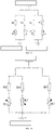
- FIG. 13 also provides a Wheatstone half-bridge circuit formed by the strain gauge 40 shown in FIG. 10
- FIG. 14 provides another Wheatstone half-bridge circuit formed by the strain gauge 50 shown in FIG. 11 and FIG. 12 .
- R0 is a fixed resistor
- the resistor R1 with an upward arrow refers to the longitudinal sensitive grid 12
- the resistor R2 with a downward arrow refers to the lateral sensitive grid 13. It is obvious that the Wheatstone half-bridge circuit provided in FIG. 14 has a simpler structure and a less wiring, and is more convenient to be calculated.
- this embodiment also provides a force sensor 60, specifically as shown in FIG. 15 and FIG. 16 . Only the points different from the force sensor 20 in Embodiment 1 are described below.
- the force sensor 60 includes an elastic body 61 and at least two strain gauges disposed on the elastic body 61.
- the at least two strain gauges are arranged on different circumferences of the elastic body 61 along the axial direction and are circumferentially arranged in a staggered manner.
- the two strain gauges are a first strain gauge and a second strain gauge.
- the first strain gauge is the strain gauge 10 of Embodiment 1
- the second strain gauge is the strain gauge 50 of Embodiment 2. That is, the strain gauge 10 includes one substrate, one longitudinal sensitive grid 12, and one lateral sensitive grid 13.
- the strain gauge 50 includes another substrate, at least two longitudinal sensitive grids 12, and at least one lateral sensitive grid 13.
- the two strain gauges composed of the first strain gauge and the second strain gauge, can also sense the strain at three different positions on the elastic body 61, thereby ensuring the actual requirements of the contact force measurement.
- the number of hollow grooves 611 formed on the elastic body 61 in the circumferential direction can be reduced to at least two, preferably two, to meet the basic measurement requirements. Therefore, the length of the elastic body 61 is shorter than the conventional one.
- one strain gauge is disposed between opposite ends of each hollow groove 611. Certainly, same as the Embodiment 1, each of opposite ends of each hollow groove 611 is also provided with one axial groove 612.
- the distal end is connected to the force sensor 60, and the hardness of the distal end of radiofrequency ablation catheter is higher than that of other parts of the radiofrequency ablation catheter, so that the ablation electrode 30 is able to contact the vessel wall or tissue through the axial pressure.
- the length of the distal end of the radiofrequency ablation catheter can be shortened accordingly, which facilitates the bending of the catheter during implantation for smooth introduction.
- the strain gauge 10 is closer to the end of the force sensor connected to an electrode than the strain gauge 50.
- the two strain gauges 10, 50 are preferably uniformly distributed at 180° in the circumferential direction of the elastic body 61.
- the present application also provides an interventional medical catheter, including a catheter and a force sensor connected to the catheter distal end.
- the force sensor is the force sensor provided in the present application.
- the interventional medical catheter also includes an electrode coupled to the force sensor.
- the electrode connected to the force sensor is an ablation electrode, which can also be a mapping electrode.
- ablation electrode which can also be a mapping electrode.
- the force sensor is connected to the ablation electrode.
- the force exerted by the distal end of the catheter on the vessel wall or tissue causes the vessel wall or tissue to generate a reactive force acting on the catheter distal end.
- the reactive force is the contact force to be measured by the present application.
- one substrate is provided with only two longitudinal sensitive grids.
- Three or more longitudinal sensitive grids can also be provided, as long as two adjacent longitudinal sensitive grids share one lateral sensitive grid.
- the plurality of longitudinal sensitive grids are parallel to and aligned with one another, and the lateral sensitive grid and the longitudinal sensitive grid are parallel to and aligned with one another.
- the plurality of hollow grooves that are arranged on different circumferences and are not staggered in the circumferential direction can form a set of hollow grooves, and one strain gauge can be disposed between opposite ends of the set of hollow grooves.
- the force sensor and the interventional medical catheter provided in the present application, all sensitive grids of the strain gauge share one grounding interface allowing to reduce the number of grounding interfaces on the strain gauge. Therefore, the present application can not only save the wiring space for mounting the strain gauge on the interventional medical catheter, to facilitate the successful mounting of the strain gauge on the interventional medical catheter and to improve the adaptability of the strain gauge, but also reduce the size of the strain gauge, which in turn shortens the length of the elastic body of the force sensor as well as reduces the size of the interventional medical catheter.
- a plurality of longitudinal sensitive grids are able to be arranged on one substrate of one strain gauge, the plurality of longitudinal sensitive grids being arranged along a same direction one lateral sensitive grid being further arranged between two adjacent longitudinal sensitive grids, all the sensitive grids sharing one grounding interface.
- Such an arrangement allows to reduce the number of strain gauges used on the force sensor, (i.e., the number of strain gauges is able to be reduced from at least three to at least two), thereby enabling to reduce the length of the force sensor, and in turn shorten the length of the distal end of the interventional medical catheter and cut down the cost of use.
- all the sensitive grids are configured to share one grounding interface, and the whole size of the strain gauge integrated with the plurality of longitudinal sensitive grids is reduced, so that the length of the hollow groove provided on the elastic body of the force sensor allows to be processed longer along the circumferential direction of the elastic body, and thus the strain gauge located between opposite ends of the hollow groove is able to sense a stronger strain signal. In this case, a better measurement is achieved.
Landscapes
- Health & Medical Sciences (AREA)
- Life Sciences & Earth Sciences (AREA)
- Engineering & Computer Science (AREA)
- Physics & Mathematics (AREA)
- Surgery (AREA)
- General Health & Medical Sciences (AREA)
- Animal Behavior & Ethology (AREA)
- Veterinary Medicine (AREA)
- Public Health (AREA)
- Biomedical Technology (AREA)
- Heart & Thoracic Surgery (AREA)
- General Physics & Mathematics (AREA)
- Medical Informatics (AREA)
- Molecular Biology (AREA)
- Nuclear Medicine, Radiotherapy & Molecular Imaging (AREA)
- Otolaryngology (AREA)
- Plasma & Fusion (AREA)
- Biophysics (AREA)
- Pulmonology (AREA)
- Anesthesiology (AREA)
- Hematology (AREA)
- Cardiology (AREA)
- Oral & Maxillofacial Surgery (AREA)
- Pathology (AREA)
- Measurement Of Length, Angles, Or The Like Using Electric Or Magnetic Means (AREA)
- Force Measurement Appropriate To Specific Purposes (AREA)
- Measuring And Recording Apparatus For Diagnosis (AREA)
- Measuring Fluid Pressure (AREA)
- Measurement And Recording Of Electrical Phenomena And Electrical Characteristics Of The Living Body (AREA)
Description
- The present application relates to the technical field of medical equipment, and in particular, to a strain gauge, a force sensor and an interventional medical catheter.
- For cardiac radiofrequency ablation catheters, strain gauges are generally provided thereon to measure the contact force between distal end of the catheter and the tissue or vessel wall, so as to accurately monitor the implementation process of the ablation treatment, thereby ensuring the successful rate of the operation. Due to the low price, fast response, large measuring range and stable performance, the strain gauge has been widely used in the interventional medical field.
- Generally, the strain gauge is made by attaching a metal sensitive grid to a substrate of plastic film. The metal sensitive grid is a set of parallel wires formed by arranging a narrow conductor in a zigzag mode. When stretched, the sensitive grid becomes narrower or longer, and the resistance becomes larger. When compressed, the sensitive grid becomes thicker or shorter, and the resistance becomes smaller. Then, the strain gauge is disposed at the periphery of the elastic body. In this case, when the elastic body is deformed due to the electrode at the top of the elastic body that is subjected to a stress, the sensitive grid of the strain gauge on the elastic body is triggered to become longer or shorter, which in turn causes a corresponding change in resistance.
- The resistance strain gauges commonly used on the market are strain gauges based on copper-nickel alloys that generally only have longitudinally arranged sensitive grids and a large circumferential surface area of the grid filament. Although the sensitivity coefficient can reach 2.0, the strain gauges based on copper-nickel alloys are significantly affected by the external temperature. Therefore, the strain gauge can only be used under conditions of dryness, no scouring and tight temperature control. However, for a cardiac radiofrequency ablation catheter, a temperature change of 25-75°C is generated during the in vivo ablation, resulting in a temperature error of the measurement causes by the corresponding temperature change in the measured circumstance. Two main factors lead to the temperature error of the strain gauge. One is the temperature coefficient of the self-resistance of the sensitive grid and the other is the thermal expansion coefficients of the material of the strain gauge's substrate and the material of the testing material.
- In addition, due to the large size of the existing strain gauge, the application of the strain gauge to the ablation catheter has been limited in a certain degree for that the strain gauges cannot be fitted with the ablation catheter in the axial direction.
- Therefore, since the existing strain gauges have certain limitations, it is necessary to develop a strain gauge that has a small size, an easy installation on the interventional medical catheter, and a good performance in precision and sensitivity, as well as an insusceptible property by temperature.
- Document
CN 201 594 006 U discloses a low energy consumption weight sensor, comprising an elastomer, a half-bridge strain gauge and a capacitor circuit. - Document
CN 201 837 447 U discloses an elastic body of weighing sensor, having a first blind hole and a second blind hole disposed thereon. - Document
CN1776385A discloses a six-dimensional force sensor integrated strain gauge composed of three groups of 90° mode double grids and three groups of shear mode double grids. - Document
CN 106 264 719 A discloses an electrophysiology catheter. - It is an object of the present application to provide a strain gauge, a force sensor and an interventional medical catheter for solving the problem that the strain gauge on the existing interventional medical catheter has a large size and certain limitations in application.
- The invention is defined in the independent claims. Embodiments of the invention are set out in the dependent claims.
- In summary, in the strain gauge, the force sensor and the interventional medical catheter provided in the present application, all sensitive grids of the strain gauge share one grounding interface allowing to reduce the number of grounding interfaces on the strain gauge. Therefore, the present application can not only save the wiring space for mounting the strain gauge on the interventional medical catheter, to facilitate the successful mounting of the strain gauge on the interventional medical catheter and to improve the adaptability of the strain gauge, but also reduce the size of the strain gauge, which in turn shortens the length of the elastic body of the force sensor as well as reduces the size of the interventional medical catheter.
- Moreover, according to the claimed invention, a plurality of longitudinal sensitive grids are able to be arranged on one substrate of one strain gauge, the plurality of longitudinal sensitive grids being arranged along a same direction, one lateral sensitive grid being further arranged between two adjacent longitudinal sensitive grids, and all the sensitive grids sharing one grounding interface. Such an arrangement allows to reduce the number of strain gauges used on the force sensor, (i.e., the number of strain gauges is able to be reduced from at least three to at least two), thereby enabling to reduce the length of the force sensor, and in turn shorten the length of the distal end of the interventional medical catheter and cut down the cost of use.
- In addition, in the strain gauge according to the claimed invention, all the sensitive grids are configured to share one grounding interface, and the whole size of the strain gauge integrated with the plurality of longitudinal sensitive grids is reduced, so that the length of the hollow groove provided on the elastic body of the force sensor allows to be processed longer along the circumferential direction of the elastic body, and thus the strain gauge located between opposite ends of the hollow groove is able to sense a stronger strain signal. In this case, a better measurement is achieved.
- Embodiment 1 shown in
figures 2-9 and the approach offigures 10 and13 are not according to the claimed invention and are present for illustration purposes only. -
FIG. 1 is a schematic structural diagram of a conventional strain gauge in which a longitudinal sensitive grid and a lateral sensitive grid are independent of each other; -
FIG. 2 is an isometric view of a strain gauge according to Embodiment 1 of the present application; -
FIG. 3 is a top view of the strain gauge shown inFIG. 2 ; -
FIG. 4 is a Wheatstone half-bridge circuit composed of the strain gauge shown inFIG. 2 ; -
FIG. 5 is a schematic structural diagram of a force sensor according to Embodiment 1 of the present application in connection with an electrode; -
FIG. 6 is a schematic diagram of three strain gauges according to Embodiment 1 of the present application uniformly distributed on an elastic body; -
FIG. 7 is a schematic diagram of a strain gauge according to Embodiment 1 of the present application mounted on an elastic body; -
FIG. 8 is a strain schematic diagram of a grid filament when the elastic body according to Embodiment 1 of the present application is subjected to a tensile stress; -
FIG. 9 is a strain schematic diagram of a grid filament when the elastic body according to Embodiment 1 of the present application is subjected to a thermal expansion; -
FIG. 10 is a schematic structural diagram of a strain gauge including two longitudinal sensitive grids and two lateral sensitive grids according toEmbodiment 2 of the present application; -
FIG. 11 is a schematic structural diagram of a preferred strain gauge according toEmbodiment 2 of the present application; -
FIG. 12 is a top view of the strain gauge shown inFIG. 11 ; -
FIG. 13 is a Wheatstone half-bridge circuit composed of the strain gauge shown inFIG. 10 ; -
FIG. 14 is a Wheatstone half-bridge circuit composed of the strain gauge shown inFIG. 12 ; -
FIG. 15 is a schematic structural diagram of a force sensor according toEmbodiment 2 of the present application in connection with an electrode; and -
FIG. 16 is a right view of the force sensor ofFIG. 15 . - 1, 2-sensitive grid; 3-grounding interface; 4-non-grounding interface;
- 10, 40, 50-strain gauge; 11-substrate; 12-longitudinal sensitive grid; 121-grid structure; 122-non-grounding interface; 123-grounding interface; 124-non-grounding lead; 125-grounding lead; 13-lateral sensitive grid;
- 20, 60-force sensor; 21, 61-elastic body; 211, 611-hollow groove; 212, 612-axial groove;
- 30-ablation electrode.
-
FIG. 1 provides a schematic structural diagram of an existing strain gauge. As shown inFIG. 1 , the strain gauge includes twosensitive grids 1, 2. For any one of the sensitive grids, one grid structure S, onegrounding interface 3, onenon-grounding interface 4, one grounding lead connected to the grounding interface 3 (the grounding lead is a grid filament connected to one end of the grid structure S of the sensitive grid), and one non-grounding lead connected to the non-grounding interface 4 (the non-grounding lead is also a grid filament connected to the other end of the grid structure S) are provided. Thegrounding interface 3 of any one of the sensitive grids can be further connected to a power grounding end through a wire, and thenon-grounding interface 4 of any one of the sensitive grids can be further connected to a power output end through a wire. - In actual use, one sensitive grid 1 is used to sense the strain of a measured object in a first direction (such as the axial direction), and the other
sensitive grid 2 is used to sense the strain of the measured object in a second direction that is perpendicular to the first direction (such as the circumferential direction). For example, the sensitive grid 1 is arranged along the axial direction of the measured object such that it can be elongated or contracted in a direction parallel to the axial direction of the measured object. Thesensitive grid 2 is arranged in the circumferential direction of the measured object such that it can be elongated or contracted in a direction parallel to the circumferential direction of the measured object. - However, the inventor finds through research that there are some problems with the foregoing strain gauges. Specifically, the two
sensitive grids 1 and 2 have four interfaces in total. In actual use, the four interfaces are connected to an external power supply through a wire, respectively. It is obvious that, in this case, lots of wires are required for connection, resulting in an increased wiring space of the strain gauge on the interventional medical catheter, which in turn increases the size of the interventional medical catheter. In addition, since the grounding interfaces of the twosensitive grids 1 and 2 are independent of each other (i.e., connected to the grid structure S through one grounding lead, respectively), when twosensitive grids 1 and 2 are arranged, the spacing formed therebetween is relatively large. Therefore, the size of the strain gauge is increased, and accordingly, the size of the corresponding interventional medical catheter is also increased, which in turn limits the successful use of the strain gauge on the interventional medical catheter. - Therefore, based on the technical problems existed in the foregoing strain gauge, the present application provides a strain gauge, which not only allows to reduce the number of grounding interfaces used so as to decrease the overall size of the strain gauge, but also enables to reduce the number of strain gauges used on the force sensor so as to decrease the length of the force sensor can be shortened, as well as the size of the interventional medical catheter. In this case, the application limitations of the strain gauge on the interventional medical catheter are overcome, thereby improving the adaptability of the strain gauge and thus promoting the success rate of the interventional treatment.
- In order to make the content of the present application more apparent and easier to be understood, the strain gauge, the force sensor and the interventional medical catheter proposed in the present application will be further described in detail with reference to the accompanying
FIG. 2-FIG.16 . Certainly, the present application is not limited to the specific embodiments, and general substitutions well known to those skilled in the art also fall within the protection scope of the present application. - Then, the present application is described in detail with reference to schematic diagrams. However, the schematic diagrams are only for the purpose of illustrating the examples of the present application and are not intended to limit the present application.
- As used herein, a "proximal end" and a "distal end" are opposing orientations, positions and directions of elements or actions relative to each other from the perspective of a surgeon using the product. Although the "proximal end" and the "distal end" are not restrictive, the "proximal end" generally refers to the end of the product that is close to the surgeon during normal operation, while the "distal end" generally refers to the end that enters into the patient at first. The "axial direction" and the "circumferential direction" refer to the axial direction and the circumferential direction of the elastic body, respectively.
- As used in the specification and the appended claims, the singular forms "a" and "the" include plural objects, unless otherwise explicitly stated. As used in the specification and the appended claims, the term "or" is used in the meaning of "and/or", unless otherwise explicitly stated.
- Embodiment 1 is not according to the invention and is present for illustration purposes only.
-
FIG. 2 is an isometric view of astrain gauge 10 according to Embodiment 1 of the present application.FIG. 3 is a top view of thestrain gauge 10 shown inFIG. 2 . As shown inFIG. 2 andFIG. 3 , thestrain gauge 10 includes asubstrate 11, and a longitudinalsensitive grid 12 and a lateralsensitive grid 13 that are disposed on thesubstrate 11. Here, the longitudinalsensitive grid 12 is generally arranged along the axial direction of the measured object (i.e., the direction of the grid length L' of the longitudinal sensitive grid is parallel to the axial direction of the measured object, and the direction of the grid width W' of the longitudinal sensitive grid is parallel to the circumferential direction of the measured object), and the lateralsensitive grid 13 is arranged along the direction that is perpendicular to the axial direction of the measured object (i.e., the direction of the grid width W' of the lateral sensitive grid is parallel to the axial direction of the measured object, and the direction of the grid length L' of the lateral sensitive grid is parallel to the circumferential direction of the measured object), similarly hereinafter. - In this embodiment, the longitudinal
sensitive grid 12 is arranged along one of the length direction and the width direction of thesubstrate 11, and the lateralsensitive grid 13 is arranged along the other of the length direction and the width direction of thesubstrate 11. Hereinafter, for ease of description, further description is made by taking the case that the longitudinalsensitive grid 12 is arranged along the length direction of thesubstrate 11, and the lateralsensitive grid 13 is arranged along the width direction of thesubstrate 11 as an example. - Herein, the length of the
substrate 11 is defined as L, and the width of thesubstrate 11 is defined as W. The direction of the grid length L' of the longitudinalsensitive grid 12 is parallel to the length direction of thesubstrate 11, and the direction of the grid width W' of the lateralsensitive grid 12 is parallel to the length direction of thesubstrate 11. In actual use, the length direction of thesubstrate 11 may be parallel to the axial direction of the measured object, so that the two sensitive gratings can sense the strain of the measured object in the axial direction and the circumferential direction that is perpendicular to the axial direction (in this case, the measured object is schematically defined to have a shape of a cylinder, a truncated cone, a cuboid or other pillar). It is obvious that under the action of strain, the two sensitive gratings are deformed in opposite ways. That is, when one of the sensitive gratings is elongated to deform along its length direction, the other sensitive grid is shortened to deform along its length direction. Specifically, when the measured object is stretched along the length direction of thesubstrate 11, the longitudinal sensitive grid 12becomes longer along the stretching direction, and the lateralsensitive grid 13 becomes shorter along a direction perpendicular to the stretching direction. In other words, the elongation and contraction direction of the longitudinalsensitive grid 12 is parallel to the length direction of thesubstrate 11, and the elongation and contraction direction of the lateralsensitive grid 13 is parallel to the width direction of thesubstrate 11. - Each sensitive grid includes one
grid structure 121, onenon-grounding interface 122, onegrounding interface 123, onenon-grounding lead 124, and onegrounding lead 125. Thegrid structure 121 is a set of parallel wires formed by arranging a narrow conductor in a zigzag mode, and the set of parallel wires has a grid shape. For any sensitive grid, thenon-grounding interface 122 and thegrounding interface 123 are respectively disposed at opposite ends of the grid structure 121and thenon-grounding interface 122 is connected to one end of thegrid structure 121 through thenon-grounding lead 124. Thenon-grounding lead 124 is formed by extending the foregoing parallel wire. Thegrounding interface 123 is connected to the other end of thegrid structure 121 through thegrounding lead 125. Thegrounding lead 125 can also be formed by extending the parallel wire of the grid structure. - Furthermore, in order to save the number of grounding interfaces of the strain gauge connected to the grounding end of the external power supply, the longitudinal
sensitive grid 12 and the lateralsensitive grid 13 are configured to share onegrounding interface 123. The sharedgrounding interface 123 can be connected to the grounding end of the external power supply through a wire, and can be connected to each of thegrid structure 121 of the longitudinalsensitive grid 12 and thegrid structure 121 of the lateralsensitive grid 13 through a same grounding lead 125.In such an arrangement, the number of interfaces are decreased from four to three, thereby reducing the number of wires of the strain gauge connected to the external power supply. Therefore, not only the wiring space for mounting the strain gauge on the interventional medical catheter is saved, so as to facilitate the successful mounting and use of the strain gauge on the interventional medical catheter, and improve the adaptability of the strain gauge, but also the size of the strain gauge is accordingly reduced due to the decreased number of interfaces, which in turn reduces the sizes of the force sensor and the interventional medical catheter with strain gauges, and helps in reducing the cost of interventional treatment and the probability of infection in patients to improve the success rate of the intervention treatment. - Preferably, all the sensitive grids are integrally formed to further reduce the size of the strain gauge.
- In this embodiment, the longitudinal
sensitive grid 12 and the lateralsensitive grid 13 are preferably parallel to and aligned with each other. That is, one of the grid width W' and the grid length L' of the longitudinalsensitive grid 12 is aligned with the other of the grid width W' and the grid length L' of the lateralsensitive grid 13. As shown inFIG. 2 , the grid length L' of the longitudinalsensitive grid 12 is aligned with the grid width W' of the lateralsensitive grid 13 when the longitudinalsensitive grid 12 is arranged along the length direction of thesubstrate 11. That is, the projection of the grid length L' of the longitudinalsensitive grid 12 in the length direction of thesubstrate 11 coincides with the grid width W' of the lateralsensitive grid 13 when the longitudinalsensitive grid 12 is arranged along the length direction of thesubstrate 11. In other embodiments, the grid width W' of the longitudinalsensitive grid 12 is aligned with the grid length L' of the lateralsensitive grid 13 when the longitudinalsensitive grid 12 is arranged along the width direction of thesubstrate 11. That is, the projection of the grid width W' of the longitudinalsensitive grid 12 in the length direction of thesubstrate 11 coincides with the grid length L' of the lateralsensitive grid 13. - More specifically, the longitudinal sensitive grid and the lateral sensitive grid that are parallel to and aligned with each other can eliminate the influence of temperature drift on the strain gauge in the axial direction of the interventional medical catheter when the length direction of the
substrate 11 is parallel to the axial direction of the measured object, e.g., the interventional medical catheter. That is, the lateralsensitive grid 13 and the longitudinalsensitive grid 12 that are parallel to and aligned with each other can provide temperature compensation for thestrain gauge 10. Here, the "temperature drift" refers to changes in parameters of the strain gauge caused by temperature changes in measured circumstance, which may cause an unstable measurement result due to the instability of an output signal from the strain gauge, and even lead to a non-work state of the strain gauge. For example, for a radiofrequency ablation catheter, the temperature generated by the distal ablation electrode during the in vivo ablation is conducted in the direction from the proximal end to the distal end of the catheter, resulting in different temperatures in the axial direction of the catheter. That is, the catheter has different temperatures at different axial heights. Therefore, in order to eliminate the effects of temperature drift at the same measurement temperature, the two sensitive grids are arranged in parallel to and alignment with each other in the axial direction of the catheter. In addition to the elimination of temperature drift, the longitudinalsensitive grid 12 and the lateralsensitive grid 13 that are arranged in parallel to and alignment with each other(i.e., at a same axial height), enable to achieve a better sense of strain for each sensitive grid, thereby improving the output strength of signal and further reducing the size of thestrain gauge 10. - In order to obtain a
strain gauge 10 with a small size, three leads 124, 125 are arranged in parallel and extending towards a same direction, preferably extending towards the proximal end of the interventional medical catheter, and the extension direction is parallel to the axial direction of the interventional medical catheter. Referring toFIG. 3 , the longitudinalsensitive grid 12 and the lateralsensitive grid 13 are arranged in parallel to each other in the width direction of thesubstrate 11, and in alignment with each other in the length direction of thesubstrate 11, thereby ensuring that the two sensitive grids can eliminate the impact of temperature drift during contact force measurement. - More preferably, each of the longitudinal
sensitive grid 12 and the lateralsensitive grid 13 is arranged in a square profile. That is, the maximum size of the profile in the length direction of thesubstrate 11 is consistent with the maximum size of the profile in the width direction of thesubstrate 11. More specifically, the size and shape of thegrid structure 121 of the longitudinalsensitive grid 12 and thegrid structure 121 of the lateralsensitive grid 13 are preferably the same. In addition, thegrid structure 121 of each sensitive grid is more preferably square, i.e., the grid width W' is equal to the grid length L', so that the length and width of the strain gauge can be reduced at the same time to make the size of the strain gauge smaller. Optionally, thegrid structure 121 of each sensitive grid can be made of an etched nickel-chromium alloy foil. More optionally, each sensitive grid has a sensitivity coefficient of 2.2 and a resistance value between 120Ω and 350Q for obtaining the strain gauge with better sensitivity and precision. - Optionally, the
grounding lead 125 connected to thecommon grounding interface 123 is located on the medial axis of the substrate 11 (i.e., thegrounding lead 125 is collinear with the medial axis). The medial axis is parallel to one of the length and width directions of thesubstrate 11. Taking thegrounding lead 125 as a reference line of installation, the mounting position of the strain gauge can be determined according to the reference line. Moreover, in actual installation, the medial axis is parallel to the axial direction of the measured object, so that the two sensitive grids sense the strain of the measured object at the same axial height of the measured object. - In this embodiment, the
substrate 11 is preferably made of a semi-rigid plastic material. For example, the material of thesubstrate 11 is selected from one or more of special molecular materials, i.e., Polyimide (PI) and Polyetheretherketone (PEEK). More preferably, thesubstrate 11 is processed from the PEEK material so that thesubstrate 11 has excellent rigidity and flexibility. Optionally, thesubstrate 11 has a thickness in a range of 5 µm to 10 µm, so as to have a certain flexibility. Optionally, the length and width of thesubstrate 11 are not greater than 2.0 mm. Preferably, the width is in a range of 1.5 mm to 2.0 mm, and the size of the substrate is small, so as to facilitate the installation of the strain gauge. - Further, the
strain gauge 10 also includes a cover film (not shown) covering each sensitive grid. In addition, the cover film can be made of the PEEK material. When both thesemi-rigid substrate 11 and the cover film have certain flexibility, thestrain gauge 10 can be used on a surface having a high curvature to facilitate the installation and use of the strain gauge. - Next, referring to
FIG. 4 , showing a Wheatstone half-bridge circuit formed by thestrain gauge 10 shown inFIG. 2 andFIG.3 , where R0 is a fixed resistor, U0 is a power voltage, and UBD is an output voltage (i.e., an electric signal output by the half-bridge circuit), R1 represents the longitudinalsensitive grid 12, and R2 represents the lateralsensitive grid 13. - As shown in
FIG. 4 , the changes of the resistance values of R1 and R2 can be amplified into voltage changes by the Wheatstone half-bridge circuit, and the direction and magnitude of the stress on the measured object can be determined by the change of the voltage. - where UBD = UBA - UAD
- UBA is a voltage of R1, and UAD is a voltage of R2.
- Further, the magnitude of the strain reflected by UBD is:

- When the grid filament of the longitudinal
sensitive grid 12 is elongated, the resistance of R1 increases, i.e., corresponding to the positive strain ε force1. Moreover, when the grid filament of the lateralsensitive grid 13 is shortened, the resistance of R2 decreases, i.e., corresponding to the negative strain ε force2. - Therefore, according to Poisson's ratio principle of material:


- Compared with the single-bridge circuit, the electrical signal output by the Wheatstone half-bridge circuit has a higher quality, which is 1.33 times of the electrical signal output by the ordinary single-bridge circuit.
- Furthermore, this embodiment also provides a
force sensor 20, specifically as shown inFIG. 5-FIG. 7 .FIG. 5 is a schematic structural diagram of theforce sensor 20 according to Embodiment 1 of the present application in connection with anablation electrode 30.FIG. 6 is a schematic diagram of threestrain gauges 10 uniformly distributed on anelastic body 21 of theforce sensor 20.FIG. 7 is a schematic diagram showing the position where thestrain gauge 10 is pasted on theelastic body 21. The following embodiments are schematically illustrated with theelastic body 21 as a cylindrical hollow elastic body herein. - Specifically, the
force sensor 20 includes anelastic body 21 and at least three strain gauges 10. The at least threestrain gauges 10 are disposed on the outer surface of theelastic body 21 to sense the axial and circumferential strains at least at three different positions of theelastic body 21. The at least threestrain gauges 10 are preferably located on different circumferences and are circumferentially arranged in a staggered manner. - The strain gauges 10 of this embodiment are preferably selected to be three, which can control the cost and avoid increasing the catheter volume under the premise of satisfying the actual requirements of contact force measurement. As shown in
FIG. 6 , the projections of the threestrain gauges 10 in the same plane are preferably uniformly distributed along the circumferential direction of theelastic body 21. That is, the orthographic projections of the threestrain gauges 10 in the same plane are uniformly arranged at 120° along the circumferential direction. - The following embodiments further illustrate the technical solution of the present application by taking the structures of three
strain gauges 10 as an example. The technical solution of the present application includes, but not limited to threestrain gauges 10, and three or more strain gauges 10. The orthographic projections of three or more strain gauges in the same plane are also preferably uniformly distributed along the circumferential direction of theelastic body 21. - Still referring to
FIG. 5 , the distal end of theelastic body 21 can be connected to theablation electrode 30. For example, theablation electrode 30 is fixed on the outer surface of theelastic body 21 through epoxy or acrylic glue, or by welding. Theelastic body 21 can be a flexible plastic or rubber tube or a cut metal tube. The preferred material for the plastic or rubber tube is a polymer material such as TPU, PVC, PEBAX, nylon, silicone rubber or natural rubber. The metal tube is preferably made of a metal material having a shape memory function such as nickel-titanium alloy or stainless steel. The metal tube can be cut in such a manner that a hollow portion (i.e., a hollow groove is formed by cutting through the outer wall of the elastic body 21) is formed on the surface of the tube body. The hollow portion can be a hollow groove in the circumferential direction or the axial direction of theelastic body 21, or a spiral hollow groove formed by other cutting methods that can impart elasticity to the metal tube. - In this embodiment, the
elastic body 21 preferably has threehollow grooves 211 cut in the circumferential direction, and astrain gauge 10 is preferably disposed between opposite ends of eachhollow groove 211. In the embodiments of the present application, threehollow grooves 211 are located on different circumferences in the axial direction and are circumferentially arranged in a staggered manner. More preferably, the projections of the threehollow grooves 211 in the same plane are preferably uniformly distributed in the circumferential direction of theelastic body 21, i.e., the orthographic projections of the threehollow grooves 211 in the same plane are uniformly arranged at 120° in the circumferential direction. - In a preferred solution, each of opposite ends of each
hollow groove 211 is provided with oneaxial groove 212. Theaxial groove 212 extends along the axial direction of theelastic body 21, and the length ofaxial groove 212 along the axial direction of theelastic body 21 is not less than the grid width W' or the grid length L' of the sensitive grid. Preferably, the length of theaxial groove 212 along the axial direction of theelastic body 21 is equal to the grid width W' or the grid length L'. The consistence of the two sizes helps in indicating the paste position of the strain gauge 10.Moreover, the grid structure 121 (i.e., the grid region) of thestrain gauge 10 has the maximum strain in the region corresponding to theaxial groove 212, resulting in a stronger output signal, and a better measurement effect. In actual installation, as shown inFIG. 7 , the grid length L' of the longitudinalsensitive grid 12 is preferably aligned with theaxial groove 212 along the axial direction of theelastic body 21, and the grid width W' of the lateralsensitive grid 13 is aligned with theaxial groove 212 along the axial direction of theelastic body 21. - In addition, each
strain gauge 10 is preferably disposed on the same circumference as thehollow groove 211. Specifically, for onestrain gauge 10, the center line of each sensitive grid along the circumferential direction of theelastic body 21 and the center line of the correspondinghollow groove 211 along the circumferential direction are on the same circumference, so that the strain can be better sensed. In addition, the experimental results show that when the medial axis of thestrain gauge 10 along the axial direction of theelastic body 21 is parallel to the axis of theelastic body 21, and the sensitive grid thereof is aligned with theaxial groove 212, thestrain gauge 10 senses the largest strain, and the output signal is the strongest. Therefore, the measurement is the most accurate. - Generally, the longer the length of the hollow groove cut along the circumferential direction is, the stronger the strain electrical signal sensed by the strain gauge of the present application is. Therefore, when the size of the strain gauge provided in the present application (the size of the strain gauge can be the width W or the length L herein) is reduced, for example, by 0.5 mm in width, it is advantageous to form a longer hollow groove in the circumferential direction, so that the strain electrical signal sensed by the strain gauge is correspondingly stronger. In addition, compared with the prior art, the strain gauge provided in the present application can also reduce the number of interfaces provided thereon, and correspondingly reduce the number of wires connected to the interfaces. For example, for strain gauges having longitudinal and lateral sensitive grids, at least one 38AWG wire can be reduced. Therefore, for the entire interventional medical catheter, the wiring space inside the catheter is greatly saved, which not only facilitates wiring, but also reduce the size of the catheter.
- Next, the principle of strain measurement of this embodiment will be described in more detail with reference to
FIG. 8 andFIG. 9 . First, referring toFIG. 8 , when theelastic body 21 of theforce sensor 20 is stretched in the axial direction by the stress F, the grid filament of the longitudinalsensitive grid 12 is elongated, and the resistance of R1 is increased to generate a positive strain ε force1. Moreover, when the lateralsensitive grid 13 is compressed in the circumferential direction by the stress N, the grid filament is shortened, and the resistance of R2 is decreased to generate a negative strain ε force2.Then, the strain εforce can be finally obtained according to ε force1 and ε force2. - Then, referring to
FIG. 9 , when theelastic body 21 of theforce sensor 20 is thermally expanded, theelastic body 21 is subjected to the tension F in each direction, but the amount of expansion in each direction is the same. The grid filaments of the longitudinalsensitive grid 12 and the lateralsensitive grid 13 are both stretched, and the resistances of R1 and R2 are increased, thereby respectively generating positive strains ε tem1 and ε tem2 . ε tem1 corresponds to the longitudinalsensitive grid 12, and ε tem2 corresponds to the lateralsensitive grid 13. Moreover, the ε tem1 and ε tem2 are equal in value. From the Wheatstone half-bridge circuit shown inFIG. 4 , it can be obtained that the total strain is εtem = ε tem1 - ε tem2 , i.e., zero. That is, the Wheatstone half-bridge circuit composed of the strain gauges having the longitudinal and lateral sensitive grids can completely eliminate the influence of temperature drift. - In addition, when the
elastic body 21 is simultaneously subjected to the tensile stress and thermal expansion, the total strain is εcomb = εforce + εtem , where εtem is always zero, therefore, εcomb = εforce . - In addition, this embodiment only gives the strain results of the elastic body that is subjected to tensile stress and thermal expansion. However, the foregoing derivation processes are also applicable to the case in which the elastic body is pressed and cooled.
- The strain gauge and the force sensor provided in this embodiment are almost the same as those in Embodiment 1, and the following description is only for different points.
- In order to reduce the number of strain gauges used on the elastic body, the inventor finds that at least two longitudinal sensitive grids can be disposed on one substrate, which can also ensure the actual requirements of contact force measurement. For ease of description, the technical solutions of this embodiment are further described by taking two longitudinal sensitive grids as an example.
- In one approach, as shown in
FIG. 10 , two longitudinalsensitive grids 12 are parallel to and in aligned with each other long the width direction of the substrate, and are arranged spaced apart. Moreover, the installation direction of the two longitudinalsensitive grids 12 is parallel to the length direction of the substrate (i.e., the direction of the grid length L' of the longitudinallysensitive grid 12 is parallel to the length direction of the substrate). Two lateralsensitive grids 13 spaced apart in the width direction of the substrate are disposed between the two longitudinalsensitive grids 12. The two lateralsensitive grids 13 are parallel to and aligned with each other, and the mounting direction of the lateralsensitive grids 13 is parallel to the width direction of the substrate (i.e., the direction of the grid length L' of the lateralsensitive grid 13 is parallel to the width direction of the substrate). - In
FIG. 10 , one of the lateralsensitive grids 13 forms a group with one longitudinalsensitive grid 12 adjacent thereto, and the other one of the lateralsensitive grids 13 also forms a group with the other longitudinalsensitive grid 12 adjacent thereto. Moreover, in each group, the two sensitive grids share one grounding interface. Therefore, thestrain gauge 40 formed by the four sensitive grids actually has six interfaces, so that there are many wires connected to the interfaces, and the width size of thestrain gauge 40 is relatively large. The width W of thestrain gauge 40 is increased by about one time the width W of thestrain gauge 10 in Embodiment 1. - In another approach, as shown in
FIG. 11 andFIG. 12 , the two longitudinalsensitive grids 12 are spaced apart in the width direction of the substrate, and are parallel to and aligned with each other. Only one lateralsensitive grid 13 is arranged between the two longitudinalsensitive grids 12, so that the two longitudinalsensitive grids 12 share one lateralsensitive grid 13, and the two longitudinalsensitive grids 12 share one grounding interface with the lateralsensitive grid 13. Therefore, thestrain gauge 50 composed of the three sensitive grids actually requires only four ports. That is, there are only four wires needed for connection. Therefore, the number of wires used is relatively small, and the width W of thestrain gauge 50 can be limited to 2 mm or less to obtain a small size ofstrain gauge 50. In this embodiment, thestrain gauge 50 can reduce two 38AWG wires compared to the foregoingstrain gauge 40, which further save the wiring space inside the catheter. - In addition,
FIG. 13 also provides a Wheatstone half-bridge circuit formed by thestrain gauge 40 shown inFIG. 10 , andFIG. 14 provides another Wheatstone half-bridge circuit formed by thestrain gauge 50 shown inFIG. 11 andFIG. 12 . R0 is a fixed resistor, the resistor R1 with an upward arrow refers to the longitudinalsensitive grid 12, and the resistor R2 with a downward arrow refers to the lateralsensitive grid 13. It is obvious that the Wheatstone half-bridge circuit provided inFIG. 14 has a simpler structure and a less wiring, and is more convenient to be calculated. - Further, this embodiment also provides a
force sensor 60, specifically as shown inFIG. 15 and FIG. 16 . Only the points different from theforce sensor 20 in Embodiment 1 are described below. - The
force sensor 60 includes anelastic body 61 and at least two strain gauges disposed on theelastic body 61. The at least two strain gauges are arranged on different circumferences of theelastic body 61 along the axial direction and are circumferentially arranged in a staggered manner. For example, the two strain gauges are a first strain gauge and a second strain gauge. The first strain gauge is thestrain gauge 10 of Embodiment 1, and the second strain gauge is thestrain gauge 50 ofEmbodiment 2. That is, thestrain gauge 10 includes one substrate, one longitudinalsensitive grid 12, and one lateralsensitive grid 13. Thestrain gauge 50 includes another substrate, at least two longitudinalsensitive grids 12, and at least one lateralsensitive grid 13. - Different from the foregoing
force sensor 20, the two strain gauges, composed of the first strain gauge and the second strain gauge, can also sense the strain at three different positions on theelastic body 61, thereby ensuring the actual requirements of the contact force measurement. However, it is advantageous to reduce the actual number of strain gauges used on theforce sensor 20. Therefore, the axial length of theelastic body 61 can be shorter, and accordingly, the length of the interventional medical catheter with theforce sensor 60 can also be shortened, thereby saving the cost of use. - Then, the number of
hollow grooves 611 formed on theelastic body 61 in the circumferential direction can be reduced to at least two, preferably two, to meet the basic measurement requirements. Therefore, the length of theelastic body 61 is shorter than the conventional one. Same as the Embodiment 1, one strain gauge is disposed between opposite ends of eachhollow groove 611. Certainly, same as the Embodiment 1, each of opposite ends of eachhollow groove 611 is also provided with oneaxial groove 612. - For the radiofrequency ablation catheter, the distal end is connected to the
force sensor 60, and the hardness of the distal end of radiofrequency ablation catheter is higher than that of other parts of the radiofrequency ablation catheter, so that theablation electrode 30 is able to contact the vessel wall or tissue through the axial pressure. In order to obtain a better flexibility, the length of the distal end of the radiofrequency ablation catheter can be shortened accordingly, which facilitates the bending of the catheter during implantation for smooth introduction. - In a preferred solution, the
strain gauge 10 is closer to the end of the force sensor connected to an electrode than thestrain gauge 50. In this case, it is advantageous to access the at least four wires connected to thestrain gauge 50 to wire holes on the outer surface of theelastic body 61, so as to shorten the wiring route. As shown inFIG. 16 , the twostrain gauges elastic body 61. - Finally, based on the foregoing embodiments, the present application also provides an interventional medical catheter, including a catheter and a force sensor connected to the catheter distal end. The force sensor is the force sensor provided in the present application. The interventional medical catheter also includes an electrode coupled to the force sensor. However, the present application does not limit that the electrode connected to the force sensor is an ablation electrode, which can also be a mapping electrode. For brevity, it is assumed in the foregoing description that the force sensor is connected to the ablation electrode. Those skilled in the art should modify the foregoing description, and the description will be applied to other types of electrodes after appropriate modifications in detail. The force exerted by the distal end of the catheter on the vessel wall or tissue causes the vessel wall or tissue to generate a reactive force acting on the catheter distal end. The reactive force is the contact force to be measured by the present application.
- In addition, the preferred embodiments of the present application are as described above, but are not limited to the scope disclosed in the foregoing embodiments. For example, it is not limited that one substrate is provided with only two longitudinal sensitive grids. Three or more longitudinal sensitive grids can also be provided, as long as two adjacent longitudinal sensitive grids share one lateral sensitive grid. Preferably, the plurality of longitudinal sensitive grids are parallel to and aligned with one another, and the lateral sensitive grid and the longitudinal sensitive grid are parallel to and aligned with one another. In addition, the plurality of hollow grooves that are arranged on different circumferences and are not staggered in the circumferential direction can form a set of hollow grooves, and one strain gauge can be disposed between opposite ends of the set of hollow grooves.
- In summary, in the strain gauge, the force sensor and the interventional medical catheter provided in the present application, all sensitive grids of the strain gauge share one grounding interface allowing to reduce the number of grounding interfaces on the strain gauge. Therefore, the present application can not only save the wiring space for mounting the strain gauge on the interventional medical catheter, to facilitate the successful mounting of the strain gauge on the interventional medical catheter and to improve the adaptability of the strain gauge, but also reduce the size of the strain gauge, which in turn shortens the length of the elastic body of the force sensor as well as reduces the size of the interventional medical catheter.
- Moreover, according to a preferred embodiment of the present application, a plurality of longitudinal sensitive grids are able to be arranged on one substrate of one strain gauge, the plurality of longitudinal sensitive grids being arranged along a same direction one lateral sensitive grid being further arranged between two adjacent longitudinal sensitive grids, all the sensitive grids sharing one grounding interface. Such an arrangement allows to reduce the number of strain gauges used on the force sensor, (i.e., the number of strain gauges is able to be reduced from at least three to at least two), thereby enabling to reduce the length of the force sensor, and in turn shorten the length of the distal end of the interventional medical catheter and cut down the cost of use.
- In addition, in the strain gauge according to a preferred embodiment of the present application, all the sensitive grids are configured to share one grounding interface, and the whole size of the strain gauge integrated with the plurality of longitudinal sensitive grids is reduced, so that the length of the hollow groove provided on the elastic body of the force sensor allows to be processed longer along the circumferential direction of the elastic body, and thus the strain gauge located between opposite ends of the hollow groove is able to sense a stronger strain signal. In this case, a better measurement is achieved.
- The above description is only for the description of preferred embodiments of the present application, and is not intended to limit the scope of the present application.
- The scope of the invention is defined by the appended claims.
Claims (15)
- A strain gauge (10, 40, 50), comprising a substrate (11) and a plurality of sensitive grids (1, 2) disposed on the substrate (11), wherein the plurality of sensitive grids (1, 2) comprises a plurality of longitudinal sensitive grids (12) and at least one lateral sensitive grid (13), which are arranged in two directions that are perpendicular to each other and share one grounding interface (3, 123), and one lateral sensitive grid (13) is disposed between two adjacent longitudinal sensitive grids (12), and all of the longitudinal sensitive grids (12) and the lateral sensitive grid (13) share one grounding interface (3,123) .
- The strain gauge (10, 40, 50) according to claim 1, wherein the substrate (11) has a first direction and a second direction, the first direction being one of a length direction of the substrate (11) and a width direction of the substrate (11), the second direction being the other one of the length direction of the substrate (11) and the width direction of the substrate (11); and wherein the plurality of longitudinal sensitive grids (12) are disposed along the first direction, and the at least one lateral sensitive grid (13) is disposed along the second direction.
- The strain gauge (10, 40, 50) according to claim 2, wherein the plurality of longitudinal sensitive grids (12) are parallel to and aligned with each other and arranged along the first direction and
wherein a grid width of the longitudinal sensitive grid (12) is aligned with a grid length of the lateral sensitive grid (13), or a grid length of the longitudinal sensitive grid (12) is aligned with a grid width of the lateral sensitive grid (13). - The strain gauge (10, 40, 50) according to claims 2 or 3, wherein all of the sensitive grids (1, 2) share one grounding lead (125), the grounding lead (125) being connected to the grounding interface (3, 123), and all of the sensitive grids (1, 2) are integrally formed, preferably,
the one shared grounding lead (125) being located on an axis parallel to the length direction of the substrate (11) or the width direction of the substrate (11). - The strain gauge (10, 40, 50) according to claim 4, wherein each sensitive grid (1, 2) further has one non-grounding interface (4, 122), and the one non-grounding interface (4, 122) of each sensitive grid (1, 2) is connected to one non-grounding lead (124), and wherein all of the grounding leads (125) and all of the non-grounding leads (124) are arranged in parallel and extending towards a same direction.
- The strain gauge (10, 40, 50) according to claim 5, wherein the longitudinal sensitive grids (12) and the lateral sensitive grids (13) are equal in grid width and grid length, and all of the longitudinal sensitive grids (12) and the lateral sensitive grids (13) have a same grid structure (121).
- The strain gauge (10, 40, 50) according to any one of claims 1 to 3, wherein each of a length of the substrate (11) and a width of the substrate (11) is not greater than 2.0 mm.
- A force sensor (20, 60), comprising an elastic body (21. 61) and at least one strain gauge (10, 40, 50) according to any one of claims 1-7, wherein the at least one strain gauge (10, 40, 50) is disposed on the elastic body (21, 61).
- The force sensor (20, 60) according to claim 8, wherein a plurality of strain gauges (10, 40, 50) are provided, and the plurality of strain gauges (10, 40, 50) are arranged on different circumferences along an axial direction of the elastic body (21, 61) and are circumferentially arranged in a staggered manner, the longitudinal sensitive grids (12) of the respective strain gauges (10, 40, 50) are arranged along the axial direction of the elastic body (21, 61); and the lateral sensitive grids (13) of the respective strain gauges (10, 40, 50) are arranged along a circumferential direction of the elastic body (21, 61), preferably,
orthographic projections of a plurality of strain gauges (10, 40, 50) in a same plane in the axial direction being uniformly distributed in the circumferential direction. - The force sensor (20, 60) according to claim 9, wherein a plurality of strain gauges (10, 40, 50) are provided, and the plurality of strain gauges (10, 40, 50) comprise at least a first strain gauge (10, 40, 50) and a second strain gauge (10, 40, 50),wherein the first strain gauge (10, 40, 50) is the strain gauge (10, 40, 50) comprising one substrate (11), one longitudinal sensitive grid (12) and one lateral sensitive grid (13), the one longitudinal sensitive grid (12) being arranged along the axial direction of the elastic body (21, 61), the one lateral sensitive grid (13) being arranged along the circumferential direction of the elastic body (21, 61),and the second strain gauge (10, 40, 50) is the strain gauge (10, 40, 50) comprising another one substrate (11), a plurality of longitudinal sensitive grids (12), and at least one lateral sensitive grid (13), the plurality of longitudinal sensitive grids (12) being parallel to and aligned with each other and arranged along the axial direction of the elastic body (21, 61), one lateral sensitive grid (13) being disposed between two adjacent longitudinal sensitive grids (12), the at least one lateral sensitive grid (13) being arranged along the circumferential direction of the elastic body (21, 61), and wherein all of the longitudinal sensitive grids (12) and the lateral sensitive grids (13) of the second strain gauge (10, 40, 50) share one grounding interface (3, 123).
- The force sensor (20, 60) according to claim 8, wherein a plurality of hollow grooves (211, 611) are formed on the elastic body (21, 61), each hollow groove (211, 611) extending along the circumferential direction of the elastic body (21, 61), wherein the plurality of hollow grooves (211, 611) are located on different circumferences along the axial direction of the elastic body (21, 61) and are circumferentially arranged in a staggered manner, and one strain gauge (10, 40, 50) is disposed between opposite ends of each hollow groove (211, 611).
- The force sensor (20, 60) according to claim 11, wherein each of the opposite ends of each hollow groove (211, 611) is provided with one axial groove (612) that extends along the axial direction of the elastic body (21, 61).
- The force sensor (20, 60) according to claim 12, wherein the sensitive grid (1, 2) of the strain gauge (10, 40, 50) is aligned with the axial groove (612) along the axial direction of the elastic body (21, 61).
- An interventional medical catheter, characterized in that, comprising a catheter distal end, wherein the catheter distal end is provided with a force sensor (20, 60) according to any one of claims 8 to 13.
- An interventional medical catheter, characterized in that, comprising a catheter distal end and an electrode, wherein the catheter distal end is provided with a force sensor (20, 60) according to claim 10, and the electrode is coupled to the force sensor (20, 60), wherein the first strain gauge (10, 40, 50) is closer to the electrode than the second strain gauge (10, 40, 50).
Applications Claiming Priority (2)
| Application Number | Priority Date | Filing Date | Title |
|---|---|---|---|
| CN201710452426.4A CN109141697B (en) | 2017-06-15 | 2017-06-15 | Strain gauge, pressure sensor and interventional medical catheter |
| PCT/CN2018/090483 WO2018228290A1 (en) | 2017-06-15 | 2018-06-08 | Strain gauge, pressure sensor, and interventional medical catheter |
Publications (3)
| Publication Number | Publication Date |
|---|---|
| EP3640578A1 EP3640578A1 (en) | 2020-04-22 |
| EP3640578A4 EP3640578A4 (en) | 2020-06-17 |
| EP3640578B1 true EP3640578B1 (en) | 2023-01-11 |
Family
ID=64658931
Family Applications (1)
| Application Number | Title | Priority Date | Filing Date |
|---|---|---|---|
| EP18817780.2A Active EP3640578B1 (en) | 2017-06-15 | 2018-06-08 | Strain gauge, pressure sensor, and interventional medical catheter |
Country Status (5)
| Country | Link |
|---|---|
| US (2) | US11596493B2 (en) |
| EP (1) | EP3640578B1 (en) |
| CN (1) | CN109141697B (en) |
| ES (1) | ES2939950T3 (en) |
| WO (1) | WO2018228290A1 (en) |
Families Citing this family (15)
| Publication number | Priority date | Publication date | Assignee | Title |
|---|---|---|---|---|
| CN106264719B (en) * | 2016-07-29 | 2019-07-23 | 上海微创电生理医疗科技股份有限公司 | Electrophysiologicalcatheter catheter |
| US10595951B2 (en) | 2016-08-15 | 2020-03-24 | Covidien Lp | Force sensor for surgical devices |
| EP3410060A1 (en) * | 2017-05-29 | 2018-12-05 | voestalpine Stahl GmbH | Strain gauge and metal strip having a coating for such a strain gauge |
| CN111973860B (en) * | 2019-05-21 | 2022-08-09 | 微创投资控股有限公司 | Medical device and medical catheter thereof |
| CN112824843B (en) * | 2019-11-21 | 2024-07-26 | 上海微创电生理医疗科技股份有限公司 | Strain gauge, pressure sensor and interventional medical catheter |
| CN116171376A (en) * | 2020-06-12 | 2023-05-26 | 液态电线公司 | Multi-axis differential strain sensor |
| CN112197687B (en) * | 2020-09-27 | 2022-04-05 | 四川锦江电子科技有限公司 | Strain gauge for catheter |
| US20230349684A1 (en) * | 2020-12-17 | 2023-11-02 | Shenzhen University | System and method for measuring rock volume change under microwave irradiation |
| CN112833770B (en) * | 2021-02-26 | 2022-12-13 | 中航电测仪器股份有限公司 | Compound full-bridge strain gauge |
| JP7537836B2 (en) | 2021-05-26 | 2024-08-21 | ミネベアミツミ株式会社 | Vital Sensor |
| US20240268692A1 (en) * | 2021-05-26 | 2024-08-15 | Minebea Mitsumi Inc. | Vital sensor |
| CN114305671B (en) * | 2021-12-30 | 2024-03-12 | 上海宏桐实业有限公司 | Catheter ablation system |
| CN114935302B (en) * | 2022-07-22 | 2022-09-23 | 山东安驰新能源科技有限公司 | Tolerance detection device and method for first shell of differential mechanism of electric vehicle |
| KR20240082068A (en) * | 2022-12-01 | 2024-06-10 | 고려대학교 산학협력단 | Smart catheter including strain sensor and catheter treatment method using the same |
| CN116067537B (en) * | 2023-02-01 | 2024-05-03 | 大诚精密医疗技术(深圳)有限公司 | Piezoresistive sensor sensing circuit, medical catheter and medical monitoring system |
Family Cites Families (14)
| Publication number | Priority date | Publication date | Assignee | Title |
|---|---|---|---|---|
| US4683755A (en) | 1985-11-15 | 1987-08-04 | Imo Delaval Inc. | Biaxial strain gage systems |
| JPH06186096A (en) * | 1992-12-15 | 1994-07-08 | Ishida Co Ltd | Distortion gauge and manufacture thereof |
| CN100351622C (en) * | 2005-12-06 | 2007-11-28 | 哈尔滨工业大学 | Six-dimensional force sensor integrated strain gauge |
| CN101190146B (en) * | 2006-11-21 | 2010-12-08 | 李楚森 | Cardiac intervention ablation catheter |
| US7726199B2 (en) | 2008-04-08 | 2010-06-01 | Wisconsin Alumni Research Foundation | Dielectrostrictive sensor for measuring deformation |
| US9101734B2 (en) * | 2008-09-09 | 2015-08-11 | Biosense Webster, Inc. | Force-sensing catheter with bonded center strut |
| CN201594006U (en) | 2009-12-02 | 2010-09-29 | 查氏电子实业(深圳)有限公司 | Low energy consumption weighing sensor and weighing machine |
| CN201569670U (en) * | 2009-12-29 | 2010-09-01 | 杭州电子科技大学 | Folded-beam type bidirectional micro-inertia sensor |
| CN201837447U (en) | 2010-11-03 | 2011-05-18 | 査氏电子实业(深圳)有限公司 | Elastic body of weighing sensor |
| CN103615967B (en) * | 2013-11-30 | 2016-09-21 | 中航电测仪器股份有限公司 | A kind of high temperature foil strain gauge and manufacture method thereof |
| CN203657736U (en) * | 2013-12-04 | 2014-06-18 | 王亚洲 | High temperature resistance strain gauge |
| CN105241371B (en) * | 2015-10-28 | 2018-03-13 | 上海应用技术学院 | Resistance strain gage |
| CN106264719B (en) * | 2016-07-29 | 2019-07-23 | 上海微创电生理医疗科技股份有限公司 | Electrophysiologicalcatheter catheter |
| CN106606373B (en) * | 2016-08-30 | 2019-02-12 | 四川锦江电子科技有限公司 | A kind of ablation catheter of accurate dynamometry |
-
2017
- 2017-06-15 CN CN201710452426.4A patent/CN109141697B/en active Active
-
2018
- 2018-06-08 US US16/622,743 patent/US11596493B2/en active Active
- 2018-06-08 WO PCT/CN2018/090483 patent/WO2018228290A1/en unknown
- 2018-06-08 ES ES18817780T patent/ES2939950T3/en active Active
- 2018-06-08 EP EP18817780.2A patent/EP3640578B1/en active Active
-
2023
- 2023-02-01 US US18/162,903 patent/US20230165656A1/en active Pending
Also Published As
| Publication number | Publication date |
|---|---|
| CN109141697B (en) | 2020-04-10 |
| ES2939950T3 (en) | 2023-04-28 |
| CN109141697A (en) | 2019-01-04 |
| US11596493B2 (en) | 2023-03-07 |
| EP3640578A1 (en) | 2020-04-22 |
| US20230165656A1 (en) | 2023-06-01 |
| WO2018228290A1 (en) | 2018-12-20 |
| US20200100859A1 (en) | 2020-04-02 |
| EP3640578A4 (en) | 2020-06-17 |
Similar Documents
| Publication | Publication Date | Title |
|---|---|---|
| EP3640578B1 (en) | Strain gauge, pressure sensor, and interventional medical catheter | |
| CN110063788B (en) | Pressure sensor and electrophysiology catheter | |
| RU2506965C2 (en) | Force-measuring catheter with attached centre spacer | |
| US20190053848A1 (en) | Design of Ablation Electrode with Tactile Sensor | |
| JP5913812B2 (en) | Catheter having a distal tip for sensing contact force | |
| US8211102B2 (en) | Contact sensing flexible conductive polymer electrode | |
| CN210774452U (en) | Strain gauge, pressure sensor and interventional medical catheter | |
| CN106974724A (en) | A kind of ablation catheter with pressure detecting function | |
| CN108720919B (en) | A kind of ablation catheter with flexible distal | |
| US20220412716A1 (en) | Strain gauge, force sensor and interventional medical catheter | |
| CN108720920B (en) | With the ablation catheter with tissue contact pressure detection function | |
| EP3974795A1 (en) | Medical device and medical catheter thereof | |
| RU2799025C1 (en) | Strain gauge, force sensor and operational medical catheter | |
| WO2017097200A1 (en) | Electrophysiology catheter | |
| CN113646605A (en) | Strain sensor unit and elongation amount regulation member | |
| CN109984838B (en) | Take electrophysiology pipe of pressure perception |
Legal Events
| Date | Code | Title | Description |
|---|---|---|---|
| STAA | Information on the status of an ep patent application or granted ep patent |
Free format text: STATUS: THE INTERNATIONAL PUBLICATION HAS BEEN MADE |
|
| PUAI | Public reference made under article 153(3) epc to a published international application that has entered the european phase |
Free format text: ORIGINAL CODE: 0009012 |
|
| STAA | Information on the status of an ep patent application or granted ep patent |
Free format text: STATUS: REQUEST FOR EXAMINATION WAS MADE |
|
| 17P | Request for examination filed |
Effective date: 20191219 |
|
| AK | Designated contracting states |
Kind code of ref document: A1 Designated state(s): AL AT BE BG CH CY CZ DE DK EE ES FI FR GB GR HR HU IE IS IT LI LT LU LV MC MK MT NL NO PL PT RO RS SE SI SK SM TR |
|
| AX | Request for extension of the european patent |
Extension state: BA ME |
|
| A4 | Supplementary search report drawn up and despatched |
Effective date: 20200520 |
|
| RIC1 | Information provided on ipc code assigned before grant |
Ipc: G01L 1/22 20060101ALI20200514BHEP Ipc: A61M 25/00 20060101ALI20200514BHEP Ipc: A61B 18/12 20060101ALI20200514BHEP Ipc: G01B 7/16 20060101AFI20200514BHEP |
|
| DAV | Request for validation of the european patent (deleted) | ||
| DAX | Request for extension of the european patent (deleted) | ||
| GRAJ | Information related to disapproval of communication of intention to grant by the applicant or resumption of examination proceedings by the epo deleted |
Free format text: ORIGINAL CODE: EPIDOSDIGR1 |
|
| GRAP | Despatch of communication of intention to grant a patent |
Free format text: ORIGINAL CODE: EPIDOSNIGR1 |
|
| GRAP | Despatch of communication of intention to grant a patent |
Free format text: ORIGINAL CODE: EPIDOSNIGR1 |
|
| STAA | Information on the status of an ep patent application or granted ep patent |
Free format text: STATUS: GRANT OF PATENT IS INTENDED |
|
| INTG | Intention to grant announced |
Effective date: 20220812 |
|
| GRAS | Grant fee paid |
Free format text: ORIGINAL CODE: EPIDOSNIGR3 |
|
| GRAA | (expected) grant |
Free format text: ORIGINAL CODE: 0009210 |
|
| STAA | Information on the status of an ep patent application or granted ep patent |
Free format text: STATUS: THE PATENT HAS BEEN GRANTED |
|
| AK | Designated contracting states |
Kind code of ref document: B1 Designated state(s): AL AT BE BG CH CY CZ DE DK EE ES FI FR GB GR HR HU IE IS IT LI LT LU LV MC MK MT NL NO PL PT RO RS SE SI SK SM TR |
|
| REG | Reference to a national code |
Ref country code: GB Ref legal event code: FG4D |
|
| REG | Reference to a national code |
Ref country code: CH Ref legal event code: EP |
|
| REG | Reference to a national code |
Ref country code: DE Ref legal event code: R096 Ref document number: 602018045367 Country of ref document: DE |
|
| REG | Reference to a national code |
Ref country code: IE Ref legal event code: FG4D |
|
| REG | Reference to a national code |
Ref country code: AT Ref legal event code: REF Ref document number: 1543678 Country of ref document: AT Kind code of ref document: T Effective date: 20230215 |
|
| REG | Reference to a national code |
Ref country code: NL Ref legal event code: FP |
|
| REG | Reference to a national code |
Ref country code: ES Ref legal event code: FG2A Ref document number: 2939950 Country of ref document: ES Kind code of ref document: T3 Effective date: 20230428 |
|
| REG | Reference to a national code |
Ref country code: LT Ref legal event code: MG9D |
|
| REG | Reference to a national code |
Ref country code: AT Ref legal event code: MK05 Ref document number: 1543678 Country of ref document: AT Kind code of ref document: T Effective date: 20230111 |
|
| PG25 | Lapsed in a contracting state [announced via postgrant information from national office to epo] |
Ref country code: RS Free format text: LAPSE BECAUSE OF FAILURE TO SUBMIT A TRANSLATION OF THE DESCRIPTION OR TO PAY THE FEE WITHIN THE PRESCRIBED TIME-LIMIT Effective date: 20230111 Ref country code: PT Free format text: LAPSE BECAUSE OF FAILURE TO SUBMIT A TRANSLATION OF THE DESCRIPTION OR TO PAY THE FEE WITHIN THE PRESCRIBED TIME-LIMIT Effective date: 20230511 Ref country code: NO Free format text: LAPSE BECAUSE OF FAILURE TO SUBMIT A TRANSLATION OF THE DESCRIPTION OR TO PAY THE FEE WITHIN THE PRESCRIBED TIME-LIMIT Effective date: 20230411 Ref country code: LV Free format text: LAPSE BECAUSE OF FAILURE TO SUBMIT A TRANSLATION OF THE DESCRIPTION OR TO PAY THE FEE WITHIN THE PRESCRIBED TIME-LIMIT Effective date: 20230111 Ref country code: LT Free format text: LAPSE BECAUSE OF FAILURE TO SUBMIT A TRANSLATION OF THE DESCRIPTION OR TO PAY THE FEE WITHIN THE PRESCRIBED TIME-LIMIT Effective date: 20230111 Ref country code: HR Free format text: LAPSE BECAUSE OF FAILURE TO SUBMIT A TRANSLATION OF THE DESCRIPTION OR TO PAY THE FEE WITHIN THE PRESCRIBED TIME-LIMIT Effective date: 20230111 Ref country code: AT Free format text: LAPSE BECAUSE OF FAILURE TO SUBMIT A TRANSLATION OF THE DESCRIPTION OR TO PAY THE FEE WITHIN THE PRESCRIBED TIME-LIMIT Effective date: 20230111 |
|
| PG25 | Lapsed in a contracting state [announced via postgrant information from national office to epo] |
Ref country code: SE Free format text: LAPSE BECAUSE OF FAILURE TO SUBMIT A TRANSLATION OF THE DESCRIPTION OR TO PAY THE FEE WITHIN THE PRESCRIBED TIME-LIMIT Effective date: 20230111 Ref country code: PL Free format text: LAPSE BECAUSE OF FAILURE TO SUBMIT A TRANSLATION OF THE DESCRIPTION OR TO PAY THE FEE WITHIN THE PRESCRIBED TIME-LIMIT Effective date: 20230111 Ref country code: IS Free format text: LAPSE BECAUSE OF FAILURE TO SUBMIT A TRANSLATION OF THE DESCRIPTION OR TO PAY THE FEE WITHIN THE PRESCRIBED TIME-LIMIT Effective date: 20230511 Ref country code: GR Free format text: LAPSE BECAUSE OF FAILURE TO SUBMIT A TRANSLATION OF THE DESCRIPTION OR TO PAY THE FEE WITHIN THE PRESCRIBED TIME-LIMIT Effective date: 20230412 Ref country code: FI Free format text: LAPSE BECAUSE OF FAILURE TO SUBMIT A TRANSLATION OF THE DESCRIPTION OR TO PAY THE FEE WITHIN THE PRESCRIBED TIME-LIMIT Effective date: 20230111 |
|
| REG | Reference to a national code |
Ref country code: DE Ref legal event code: R097 Ref document number: 602018045367 Country of ref document: DE |
|
| PG25 | Lapsed in a contracting state [announced via postgrant information from national office to epo] |
Ref country code: SM Free format text: LAPSE BECAUSE OF FAILURE TO SUBMIT A TRANSLATION OF THE DESCRIPTION OR TO PAY THE FEE WITHIN THE PRESCRIBED TIME-LIMIT Effective date: 20230111 Ref country code: RO Free format text: LAPSE BECAUSE OF FAILURE TO SUBMIT A TRANSLATION OF THE DESCRIPTION OR TO PAY THE FEE WITHIN THE PRESCRIBED TIME-LIMIT Effective date: 20230111 Ref country code: EE Free format text: LAPSE BECAUSE OF FAILURE TO SUBMIT A TRANSLATION OF THE DESCRIPTION OR TO PAY THE FEE WITHIN THE PRESCRIBED TIME-LIMIT Effective date: 20230111 Ref country code: DK Free format text: LAPSE BECAUSE OF FAILURE TO SUBMIT A TRANSLATION OF THE DESCRIPTION OR TO PAY THE FEE WITHIN THE PRESCRIBED TIME-LIMIT Effective date: 20230111 Ref country code: CZ Free format text: LAPSE BECAUSE OF FAILURE TO SUBMIT A TRANSLATION OF THE DESCRIPTION OR TO PAY THE FEE WITHIN THE PRESCRIBED TIME-LIMIT Effective date: 20230111 |
|
| PGFP | Annual fee paid to national office [announced via postgrant information from national office to epo] |
Ref country code: IT Payment date: 20230623 Year of fee payment: 6 Ref country code: ES Payment date: 20230830 Year of fee payment: 6 |
|
| PLBE | No opposition filed within time limit |
Free format text: ORIGINAL CODE: 0009261 |
|
| STAA | Information on the status of an ep patent application or granted ep patent |
Free format text: STATUS: NO OPPOSITION FILED WITHIN TIME LIMIT |
|
| PG25 | Lapsed in a contracting state [announced via postgrant information from national office to epo] |
Ref country code: SK Free format text: LAPSE BECAUSE OF FAILURE TO SUBMIT A TRANSLATION OF THE DESCRIPTION OR TO PAY THE FEE WITHIN THE PRESCRIBED TIME-LIMIT Effective date: 20230111 |
|
| 26N | No opposition filed |
Effective date: 20231012 |
|
| PG25 | Lapsed in a contracting state [announced via postgrant information from national office to epo] |
Ref country code: MC Free format text: LAPSE BECAUSE OF FAILURE TO SUBMIT A TRANSLATION OF THE DESCRIPTION OR TO PAY THE FEE WITHIN THE PRESCRIBED TIME-LIMIT Effective date: 20230111 |
|
| PG25 | Lapsed in a contracting state [announced via postgrant information from national office to epo] |
Ref country code: SI Free format text: LAPSE BECAUSE OF FAILURE TO SUBMIT A TRANSLATION OF THE DESCRIPTION OR TO PAY THE FEE WITHIN THE PRESCRIBED TIME-LIMIT Effective date: 20230111 Ref country code: MC Free format text: LAPSE BECAUSE OF FAILURE TO SUBMIT A TRANSLATION OF THE DESCRIPTION OR TO PAY THE FEE WITHIN THE PRESCRIBED TIME-LIMIT Effective date: 20230111 |
|
| REG | Reference to a national code |
Ref country code: CH Ref legal event code: PL |
|
| PG25 | Lapsed in a contracting state [announced via postgrant information from national office to epo] |
Ref country code: LU Free format text: LAPSE BECAUSE OF NON-PAYMENT OF DUE FEES Effective date: 20230608 |
|
| REG | Reference to a national code |
Ref country code: IE Ref legal event code: MM4A |
|
| PG25 | Lapsed in a contracting state [announced via postgrant information from national office to epo] |
Ref country code: LU Free format text: LAPSE BECAUSE OF NON-PAYMENT OF DUE FEES Effective date: 20230608 |
|
| PG25 | Lapsed in a contracting state [announced via postgrant information from national office to epo] |
Ref country code: IE Free format text: LAPSE BECAUSE OF NON-PAYMENT OF DUE FEES Effective date: 20230608 |
|
| PG25 | Lapsed in a contracting state [announced via postgrant information from national office to epo] |
Ref country code: IE Free format text: LAPSE BECAUSE OF NON-PAYMENT OF DUE FEES Effective date: 20230608 Ref country code: CH Free format text: LAPSE BECAUSE OF NON-PAYMENT OF DUE FEES Effective date: 20230630 |
|
| PGFP | Annual fee paid to national office [announced via postgrant information from national office to epo] |
Ref country code: GB Payment date: 20240621 Year of fee payment: 7 |
|
| PGFP | Annual fee paid to national office [announced via postgrant information from national office to epo] |
Ref country code: DE Payment date: 20240619 Year of fee payment: 7 |
|
| PGFP | Annual fee paid to national office [announced via postgrant information from national office to epo] |
Ref country code: NL Payment date: 20240619 Year of fee payment: 7 |
|
| PGFP | Annual fee paid to national office [announced via postgrant information from national office to epo] |
Ref country code: FR Payment date: 20240628 Year of fee payment: 7 |
|
| PGFP | Annual fee paid to national office [announced via postgrant information from national office to epo] |
Ref country code: BE Payment date: 20240619 Year of fee payment: 7 |