EP3640560A1 - Wind port component and air conditioner - Google Patents
Wind port component and air conditioner Download PDFInfo
- Publication number
- EP3640560A1 EP3640560A1 EP18891740.5A EP18891740A EP3640560A1 EP 3640560 A1 EP3640560 A1 EP 3640560A1 EP 18891740 A EP18891740 A EP 18891740A EP 3640560 A1 EP3640560 A1 EP 3640560A1
- Authority
- EP
- European Patent Office
- Prior art keywords
- plate body
- plate
- elastic
- air port
- port component
- Prior art date
- Legal status (The legal status is an assumption and is not a legal conclusion. Google has not performed a legal analysis and makes no representation as to the accuracy of the status listed.)
- Granted
Links
Images



Classifications
-
- F—MECHANICAL ENGINEERING; LIGHTING; HEATING; WEAPONS; BLASTING
- F24—HEATING; RANGES; VENTILATING
- F24F—AIR-CONDITIONING; AIR-HUMIDIFICATION; VENTILATION; USE OF AIR CURRENTS FOR SCREENING
- F24F13/00—Details common to, or for air-conditioning, air-humidification, ventilation or use of air currents for screening
- F24F13/08—Air-flow control members, e.g. louvres, grilles, flaps or guide plates
- F24F13/10—Air-flow control members, e.g. louvres, grilles, flaps or guide plates movable, e.g. dampers
- F24F13/14—Air-flow control members, e.g. louvres, grilles, flaps or guide plates movable, e.g. dampers built up of tilting members, e.g. louvre
- F24F13/1486—Air-flow control members, e.g. louvres, grilles, flaps or guide plates movable, e.g. dampers built up of tilting members, e.g. louvre characterised by bearings, pivots or hinges
-
- F—MECHANICAL ENGINEERING; LIGHTING; HEATING; WEAPONS; BLASTING
- F24—HEATING; RANGES; VENTILATING
- F24F—AIR-CONDITIONING; AIR-HUMIDIFICATION; VENTILATION; USE OF AIR CURRENTS FOR SCREENING
- F24F13/00—Details common to, or for air-conditioning, air-humidification, ventilation or use of air currents for screening
- F24F13/08—Air-flow control members, e.g. louvres, grilles, flaps or guide plates
-
- F—MECHANICAL ENGINEERING; LIGHTING; HEATING; WEAPONS; BLASTING
- F24—HEATING; RANGES; VENTILATING
- F24F—AIR-CONDITIONING; AIR-HUMIDIFICATION; VENTILATION; USE OF AIR CURRENTS FOR SCREENING
- F24F13/00—Details common to, or for air-conditioning, air-humidification, ventilation or use of air currents for screening
- F24F13/02—Ducting arrangements
- F24F13/06—Outlets for directing or distributing air into rooms or spaces, e.g. ceiling air diffuser
-
- F—MECHANICAL ENGINEERING; LIGHTING; HEATING; WEAPONS; BLASTING
- F24—HEATING; RANGES; VENTILATING
- F24F—AIR-CONDITIONING; AIR-HUMIDIFICATION; VENTILATION; USE OF AIR CURRENTS FOR SCREENING
- F24F1/00—Room units for air-conditioning, e.g. separate or self-contained units or units receiving primary air from a central station
- F24F1/0007—Indoor units, e.g. fan coil units
- F24F1/0011—Indoor units, e.g. fan coil units characterised by air outlets
-
- F—MECHANICAL ENGINEERING; LIGHTING; HEATING; WEAPONS; BLASTING
- F24—HEATING; RANGES; VENTILATING
- F24F—AIR-CONDITIONING; AIR-HUMIDIFICATION; VENTILATION; USE OF AIR CURRENTS FOR SCREENING
- F24F13/00—Details common to, or for air-conditioning, air-humidification, ventilation or use of air currents for screening
-
- F—MECHANICAL ENGINEERING; LIGHTING; HEATING; WEAPONS; BLASTING
- F24—HEATING; RANGES; VENTILATING
- F24F—AIR-CONDITIONING; AIR-HUMIDIFICATION; VENTILATION; USE OF AIR CURRENTS FOR SCREENING
- F24F13/00—Details common to, or for air-conditioning, air-humidification, ventilation or use of air currents for screening
- F24F13/08—Air-flow control members, e.g. louvres, grilles, flaps or guide plates
- F24F13/10—Air-flow control members, e.g. louvres, grilles, flaps or guide plates movable, e.g. dampers
- F24F13/14—Air-flow control members, e.g. louvres, grilles, flaps or guide plates movable, e.g. dampers built up of tilting members, e.g. louvre
-
- F—MECHANICAL ENGINEERING; LIGHTING; HEATING; WEAPONS; BLASTING
- F24—HEATING; RANGES; VENTILATING
- F24F—AIR-CONDITIONING; AIR-HUMIDIFICATION; VENTILATION; USE OF AIR CURRENTS FOR SCREENING
- F24F13/00—Details common to, or for air-conditioning, air-humidification, ventilation or use of air currents for screening
- F24F13/22—Means for preventing condensation or evacuating condensate
-
- F—MECHANICAL ENGINEERING; LIGHTING; HEATING; WEAPONS; BLASTING
- F24—HEATING; RANGES; VENTILATING
- F24F—AIR-CONDITIONING; AIR-HUMIDIFICATION; VENTILATION; USE OF AIR CURRENTS FOR SCREENING
- F24F13/00—Details common to, or for air-conditioning, air-humidification, ventilation or use of air currents for screening
- F24F13/22—Means for preventing condensation or evacuating condensate
- F24F2013/221—Means for preventing condensation or evacuating condensate to avoid the formation of condensate, e.g. dew
Definitions
- the present disclosure relates to the technical field of air conditioners, and in particular, to an air port component and an air conditioner.
- an air deflector is a common part used for realizing air supply or opening and closing an air door, and the main role of the air deflector in the overall structure is to guide air or open and close the air door or to achieve both functions.
- the temperature difference is large, resulting in a large deformation of the wind deflector after a period of time.
- the present disclosure provide an air port component and an air conditioner, which is capable of reducing the deformation degree of a plate body in the air port component.
- the present disclosure provides an air port component, comprising a first plate body and a second plate body, wherein two longitudinal ends of the first plate body are elastically connected with two longitudinal ends of the second plate body respectively.
- the air port component comprises an elastic component, wherein the two longitudinal ends of the first plate body are elastically connected with the two longitudinal ends of the second plate body (2) respectively through the elastic components.
- the elastic component comprises an elastic plate, and the elastic plate is connected to the longitudinal ends of the first plate body and the second plate body.
- a first preset gap exists at the connection of the elastic plate and at least one of the first plate body and the second plate body along the longitudinal direction.
- the elastic component further comprises an elastic spacer, and the elastic spacer is disposed in the first preset gap.
- the elastic spacer comprises a rubber pad, and the thickness of the rubber pad in a free state is consistent with the first preset gap; or the elastic spacer comprises a spring, and the height of the spring in the free state is consistent with the first preset gap.
- the elastic plate is disposed on the first plate body, and the elastic plate and the second plate body are detachably connected.
- a first buckle group is disposed on one side of the first plate body facing to the second plate body
- a second buckle group is disposed on one side of the second plate body facing to the first plate body
- the first buckle group is snapped with the second buckle group
- the elastic plate is located at an outer side of the longitudinal end of the second buckle group and is connected with an end of the second buckle group.
- the air port component comprises a fastener, wherein the elastic plate is connected to a longitudinal end of the second buckle group through the fastener.
- a first preset gap exists between the elastic plate and an outer end of the second buckle group along the longitudinal direction.
- the air port component comprises a flexible pad, wherein a second preset gap exists at a site on which the first buckle group matches the second buckle group, and the flexible pad is disposed between the first plate body and the second plate body and is filled in the second preset gap.
- the first buckle group comprises two groups of first buckle structures disposed at two lateral ends of the first plate body respectively, and each group of first buckle structures comprises a plurality of first buckle structures disposed at intervals along the longitudinal direction of the first plate body; and the second buckle group comprises two groups of second buckle structures disposed at two lateral ends of the second plate body respectively, and each group of second buckle structures comprises strip-shaped buckles extending along the longitudinal direction of the second plate body, and the first buckle structures match with the strip-shaped buckles correspondingly.
- a driving member mounting interface is disposed on the first plate body , so as to mount a driving member capable of driving the first plate body and the second plate body.
- the air port component comprises a cover plate, wherein the cove plate is arranged on the outer side of the elastic component, so as to seal a gap on the longitudinal ends of the first plate body and the second plate body.
- a first guide structure is disposed on one side of the first plate body facing to the second plate body
- a second guide structure is disposed on one side of the second plate body facing to the first plate body
- the first guide structure and the second guide structure are spaced differently relative to a lateral centerline of the air port component, and are installed in place when the first plate body and the second plate body are correctly mounted.
- the first guide structure and the second guide structure have different heights to form a complementary structure, preventing the first guide structure and the second guide structure from installing in place when the first plate body and the second plate body are incorrectly mounted.
- a first buckle group is disposed on one side of the first plate body facing to the second plate body, and the first guide structure is higher than the first buckle group.
- the present disclosure further provides an air conditioner, comprising the air port component.
- the corresponding longitudinal ends of the first plate body and the second plate body are elastically connected, in the case of a relatively large working environment temperature difference, even if the difference between the linear expansion coefficients of materials used by the two plate bodies is relatively large, the elastic deformation of the plate bodies due to temperature changes is also be compensated by the elastic connection mode to reduce the degree of plastic deformation of the plate bodies after being used for a period of time, thereby improving the reliability of the operation of the air port component, preventing blockage during the operation, as well as ensuring that the airflow of the air outlet meets the design requirements to prevent condensation due to local overcooling, and also ensuring the aesthetic feeling of the appearance.
- first and second appearing in the present disclosure are merely for the convenience of description, so as to distinguish different components having the same name, and do not indicate a sequential or primary-secondary relationship.
- orientation or position relationships indicated by terms such as “upper”, “lower”, “left”, “right”, “front”, “back”, lateral” and “longitudinal” and the like are orientation or position relationships shown on the basis of the drawings, and are merely for the convenience of describing the present disclosure, rather than indicating or implying that the referred devices must have specific orientations or must be constructed and operated in specific orientations, and thus cannot be construed as limiting the protection scope of the present disclosure.
- the air port component includes a first plate body 1 and a second plate body 2, and the first plate body 1 and the second plate body 2 are capable of being connected along the thickness direction through a snap-fit structure. Moreover, two longitudinal ends of the first plate body 1 are elastically connected with two longitudinal ends of the second plate body 2 respectively.
- the "longitudinal” is defined as the length direction of the plate body in the air port component
- “lateral” is defined as the width direction of the plate body in the air port component.
- the air port component in the condition that the air port component is mounded in an air conditioner, the air port component includes an air conditioner air deflector, the first plate body 1 and the second plate body 2 jointly form an air deflector of the air conditioner, the first plate body 1 is an upper air deflector and faces to the interior of the air conditioner, and the second plate body 2 is a lower air deflector and faces to the exterior of the air conditioner.
- the air port component is applied to the air conditioner.
- the first plate body 1 and the second plate body 2 are blades of a louver structure.
- the elastic deformation of the air deflectors due to temperature changes are compensated by the elastic deformation of an elastic component, so as to reduce the degree of plastic deformation of the air deflectors after a period of time, thereby improving the operation reliability of the air port component, preventing blockage during the operation, as well as ensuring that the airflow of the air outlet meets the design requirements to prevent condensation due to local overcooling, and also ensuring the aesthetic feeling of the appearance.
- the air port component of the present disclosure further include an elastic component, and two longitudinal ends of the first plate body 1 are elastically connected with two longitudinal ends of and the second plate body 2 through the elastic component.
- an elastic component in the embodiments, there is no need to change the own structure of the upper second plate greatly, and it is easy to realize elastic connection.
- the air port component in the condition with a relatively large working environment temperature difference, even if the difference between the linear expansion coefficients of the materials used by the two plate bodies is relatively large, the elastic deformation of the plate bodies due to temperature changes would also be compensated by the elastic deformation of the elastic component.
- those skilled in the art would also manufacture the longitudinal ends of the plate bodies by using elastic materials, and thus the elastic component is omitted.
- the elastic component includes an elastic plate 13, and the elastic plate 13 is connected with the corresponding longitudinal ends of the first plate body 1 and the second plate body 2.
- the elastic plate 13 could be formed as following, the elastic plate 13 is disposed at a longitudinal end of one of the first plate body 1 and the second plate body 2 and is connected with a longitudinal end of the other of the first plate body 1 and the second plate body 2 in a state in which the first plate body 1 and the second plate body 2 are snapped.
- the elastic plate 13 is a separate structural member that is detachably connected with the corresponding longitudinal ends of the first plate body 1 and the second plate body 2 respectively.
- the elasticity of the elastic plate 13 are achieved by selecting an elastic material, and the elastic plate 13 are formed as an elastic structure.
- elastic plates 13 would be disposed at the two longitudinal ends of the plate body, so as to compensate the deformation of the two longitudinal ends of the plate body due to temperature changes through the elastic deformation of the elastic plate 13.
- first plate body 1 and the second plate body 2 are snapped along the longitudinal direction by a snap-fit structure, and the ends thereof are connected by the elastic plate 13.
- the deformation, particularly, extension or retraction of the plate bodies along the longitudinal direction, of the plate bodies due to temperature changes would also be compensated by the elastic deformation of the elastic component, so as to reduce the interaction force of the first and second plate bodies along the longitudinal direction, in this way, the degree of plastic deformation of the first and second plate bodies after a period of time is reduced, for example, the original radian of the entire plate body is ensured or the straightness of the plate body is maintained.
- the material selection of the first and second plate bodies is relatively wide, such as plastic, aluminum, titanium, or aluminum-magnesium alloy and the like.
- the present disclosure reduces the degree of plastic deformation of the plate body, further, when applied to an air conditioner, this advantage would not only prevent blockage of the plate body during operation due to deformation, but also reduces abnormal noise generated by friction between the air deflector and the air conditioner main body, thereby improving the operation reliability of the air port component.
- the aesthetic feeling of the appearance of the air conditioner would also be guaranteed, and the cost is reduced.
- a first preset gap a exists at the connection between the elastic plate 13 and at least one of the first plate body 1 and the second plate body 2 along the longitudinal direction, and the first preset gap a is a gap that is reserved after the second plate body is assembled at the room temperature.
- the elastic plate 13 is both connected to a structural member existing on the plate body, such as a snap-fit structure, or a structure for connecting the elastic plate 13 only may also be additionally disposed on the plate body.
- the elastic plate 13 is disposed on the first plate body 1, and the elastic plate 13 is detachably connected with the second plate body 2.
- the elastic plate 13 and the first plate body 1 may be integrally formed by injection molding, so that the processing difficulty is reduced, and furthermore, there is a sufficient space for disposing the elastic plate 13 on the first plate body 1 facing to the interior of the air conditioner.
- the snap-fit structure between the first plate body 1 and the second plate body 2 are configured as follows.
- a first buckle group is disposed on one side of the first plate body 1 facing to the second plate body 2
- a second buckle group is disposed on one side of the second plate body 2 facing to the first plate body 1
- the first buckle group and the second buckle group collectively forms the snap-fit structure.
- the elastic plate 13 is disposed on the first plate body 1, and the elastic plate 13 is located on an outer side of the second buckle group along the longitudinal end and is connected to the end of the second buckle group in a state in which the first plate body 1 and the second plate body 2 are buckled through the first buckle group and the second buckle group.
- the second buckle group is used as a connecting structure to be connected with the elastic plate 13, the existing structure on the plate body would be utilized, moreover, the elastic plate 13 is located on the outer side of the snap-fit structure along the longitudinal direction and cover the gap between the first and second plate bodies, and prevent cold air from entering into the gap to prevent condensation.
- a first preset gap a is disposed between the elastic plate 13 and an outer end face of the second buckle group along the longitudinal direction.
- the elastic plate 13 in the case of a relatively large working environment temperature difference, even if the difference between the linear expansion coefficients of the materials of the first and second plate bodies is relatively large, since the elastic plate 13 has elasticity, and the first preset gap a exists between the elastic plate 13 and the outer end face of the second buckle group, the elastic deformation of the plate bodies due to temperature changes is compensated, and the acting force between the first and second plate bodies in the case of the elastic deformation is reduced, thereby reducing the degree of plastic deformation of the first and second plate bodies, and then the strength of the entire air port component is ensured.
- the first plate body 1 has a longitudinal elongation greater than that of the second plate body 2 since the linear expansion coefficient of the material is large. At this time, an upper end of the elastic plate 13 elastically deform outward, so that the deformation of the first and second plate bodies is minimized.
- the longitudinal amount of contraction of the first plate body 1 is greater than that of the second plate body 2.
- the elastic plate 13 elastically deform accordingly, in this way, even if the first plate body 1 contracts, it will not exert a large force on the second plate body 2 so as to minimize the deformation of the first and second plate bodies, thereby maintaining the original shape of the first and second plate bodies.
- the air port component further includes a fastener 4, and the elastic plate 13 and the longitudinal ends of the second buckle group are fixed through the fastener 4.
- a mounting hole 131 is formed in the elastic plate 13
- a threaded hole is formed in an outer end of the second buckle group along the longitudinal direction, and the fastener 4 such as a screw and the like is inserted into the mounting hole 131 and the threaded hole to achieve the fixation of the elastic plate 13 and the second buckle group.
- the first preset gap a exists between the elastic plate 13 and the outer end face of the second buckle group along the longitudinal direction by adjusting the torque on the fastener 4, instead of disposing a relatively large gap for the first and second plate bodies in the traditional pure buckle connection or glue bonding, and since the gap is formed in the inner side of the elastic plate 13, the cold air can be prevented from entering into the space between the first and second plate bodies to generate condensation.
- the elastic component includes an elastic spacer, the elastic spacer is located between the elastic plate 13 and the second buckle group, that is, disposed in the first preset gap a, and the thickness of the elastic spacer is consistent with the first preset gap a for eliminating the first preset gap a.
- the elastic spacer is a rubber pad, the rubber pad is spaced between the elastic plate 13 and the second buckle group, and the thickness of the rubber pad in a free state is consistent with the first preset gap a.
- the elastic spacer is also be a spring, the spring is disposed between the elastic plate 13 and the second buckle group, and the length of the spring in the free state is consistent with the first preset gap a.
- a method for determining the first preset gap a is descried below. Referring to Fig. 7 and Fig. 8 , the elastic plate 13 is fixed to the first plate body 1, and there is a first preset gap a between the elastic plate 13 and the outer end face of the second buckle group on the second plate body 2.
- the first plate body 1 is an injection molding part
- the second plate body 2 is an aluminum part or is made of a other lightweight high-strength materials
- the coefficient A of thermal expansion of a plastic material is higher than the coefficient B of thermal expansion of an aluminum material, therefore, the coefficient A of thermal expansion of the first plate body 1 is higher than the coefficient B of thermal expansion of the second plate body 2.
- the air port component includes a cover plate 3, the cover plate 3 is disposed on the outer side of the elastic plate 13 along the longitudinal direction of an air conditioner wind deflector, so as to seal the gap at the longitudinal ends of the first plate body 1 and the second plate body 2, so as to achieve a better anti-condensation effect.
- the base end part of the second plate body 2 has an extended end relative to the longitudinal end of the second buckle group, the length of the extended end is greater than the total thickness of the elastic plate 13 and the cover plate 3, Fig.
- FIG 3 shows a structural schematic diagram of the cover plate 3 after installation, even if the amount of contraction of the second plate body 2 is relatively large due to environment temperature changes, since the end of the second plate body 2 exceeds the outer side face of the cover plate 3, a gap between the second plate body 2 and the cover plate 3 is avoided, whic not only prevents the cold air from entering the air deflector device, but also ensures the aesthetic feeling of the appearance of the front face of the air conditioner.
- the air port component further includes a flexible pad 5, such as sponge or rubber or the like, the flexible pad 5 is disposed between the first plate body 1 and the second plate body 2, there is a second preset gap b at the connection of the first buckle group and the second buckle group, and the flexible pad 5 is filled in the second preset gap b.
- the flexible pad 5 is soft and large in compression amount, so the deformation of the first buckle group and the second buckle group due to environment temperature changes is alleviated, thereby avoiding abnormal noise; and furthermore, an effective connection is formed between the first and second plate bodies, so that the plate bodies extend or contract in the longitudinal and lateral directions.
- the first buckle group includes two groups of first buckle structures 1 disposed on two longitudinal edges of the first plate body 1 respectively, and each group of first buckle structures 11 includes a plurality of first buckle structures 11 disposed at internals along the longitudinal direction of the first plate body 1.
- the plurality of first buckle structures 11 in each group of first buckle structures 11 are evenly spaced, and an enlarged drawing B in Fig. 1 shows the shape of a single first buckle structure 11.
- the second buckle group includes two groups of second buckle structures 21 disposed at the two lateral ends of the second plate body 1 respectively, and each group of second buckle structures 21 includes strip-shaped buckles extending along the longitudinal direction of the second plate body 2.
- the section of each first buckle structure 11 is a hook-shaped structure with an outward free end
- the second plate body 2 has an arc-shaped structure
- the section of each strip-shaped buckle is a clamping structure with irregular section
- the first plate body 1 pressed downward aligning the second plate body 2
- the second plate body 2 generates elastic deformation along the lateral direction
- the distance between two strip-shaped buckles is increased, so that each first buckle structure 11 is located on the inner side of the strip-shaped buckle, and after the first plate body 1 is released, each first buckle structure 11 is clamped with the corresponding strip-shaped buckle.
- the first buckle structure 11 and a second buckle structure 21 have a second preset gap b in the height direction, and the second preset gap b is filled by the flexible pad 5 disposed between the upper second plate bodies.
- a first guide structure 12 is disposed on one side of the first plate body 1 facing to the second plate body 2, and the first guide structure 12 is located between the two groups of first buckle structures 11 in the lateral direction; and a second guide structure 22 is disposed on one side of the second plate body 2 facing to the first plate body 1, and the second guide structure 22 is located between the two groups of second buckle structures 21 in the lateral direction.
- the first guide structure 12 and the second guide structure 22 are spaced differently relative to the lateral center positions of the first plate body 1 and the second plate body 2, that is, the distance L3 between the first guide structure and one lateral end of the guide plate is unequal to the distance L4 between the second guide structure and other lateral end of the guide plate, correct installation is be achieved when the first plate body 1 and the second plate body 2 are correctly mounted, and correct installation cannot be achieved when the mounting direction of the first plate body 1 and the second plate body 2 is wrong.
- first guide structure 12 and the second guide structure 22 have different height, and thus form a complementary structure, which prevents the first guide structure and the second guide structure from cooperating in place when the first plate body 1 and the second plate body 2 are incorrectly mounted.
- the first guide structure 12 includes two frame-shaped protrusion, a partition plate is arranged in the middle of the rectangular frame protrusion along the longitudinal direction of the plate body, as shown in an enlarged view A in Fig. 1 , the two frame-shaped protrusion are respectively disposed close to the longitudinal ends of the first plate body 1.
- the second guide structure 22 includes two strip-shaped protrusions, the strip-shaped protrusions extend along the longitudinal direction of the second plate body 2, and the two strip-shaped protrusions are located between the two groups of second buckle structures 21 and spaced differently relative to the center of the second plate body 2 along the lateral direction.
- the two strip-shaped protrusion have different heights
- the left side protrusion is higher than the right side protrusion
- two side plates of each frame-shaped protrusion also has a height difference along the lateral direction, but the protrusion height of the left side plate of the frame-shaped protrusion is lower than that of the right side plate.
- the second plate body 2 is circular arc-shaped between the two strip-shaped protrusions, correspondingly, the top of the frame-shaped protrusion is designed as mating circular arc shapes, after the two plate bodies are mounted in place, a relatively small gap is retained between the two circular arc surfaces of the first and second plate bodies, so that the snap-fit structure is mounted in place.
- first guide structure 12 is higher than the first buckle group, so that it cannot be assembled in place even in the case of reverse installation, or the snap-fit structure is not damaged even if forced by external force, so as to reduce assembly errors during the production.
- the first plate body 1 is provided with a driving member mounting interface 14 for mounting a driving member capable of driving the first plate body 1 and the second plate body 2.
- the driving member mounting interface 14 is disposed on the first plate body 1, when the first plate body 1 is made of plastic, it is convenient to be integrally formed with the first plate body 1 by injection molding to reduce processing difficulty; and it plays a mutual reinforcement role with the elastic plate 13 to ensure the strength of the structure, so that the driving member stably and accurately drives the air deflector device.
- the longitudinal end of the first plate body 1 is configured as a supporting structure that arches away from the second plate body 2, the supporting structure is provided with inclined side plates 15 on both sides along the lateral direction of the first plate body 1 respectively, the bottom ends of the two side plates 15 are connected with the first plate body 1, the driving member mounting interface 14 is disposed at a position where the top ends meet, and the axial line of the driving member mounting interface 14 is consistent with the longitudinal direction of the first plate body 1.
- Two elastic plate 13 are respectively fixed to the two ends of the two side plates 15, and the two elastic plates 13 are spaced apart.
- the second plate body 2 When the air conditioner air deflector device of the present disclosure is assembled, as shown in Fig. 5 , the second plate body 2 is placed below, and the entire sponge is pasted on the inner side of the second plate body 2, and meanwhile the sponge covers the second buckle group; due to the error prevention structure, the first plate body 1 is placed above the second plate body 2 in the correct direction, and the first plate body 1 is pressed down, and by means of the guide of the first guide structure 12 and the second guide structure 22, the distance between the two air deflectors is reduced, until the first buckle group and the second buckle group are buckled in place. Finally, as shown in Fig. 4 , the elastic plate 13 and the second plate body 2 are fixed by the fastener 4.
- the present disclosure further relates to an air conditioner, including the air port component described in the above embodiment. Since such an air deflector device is not easily deformed when the environment temperature changes greatly, the air conditioner of the present disclosure at least has one of the following advantages:
Landscapes
- Engineering & Computer Science (AREA)
- Chemical & Material Sciences (AREA)
- Combustion & Propulsion (AREA)
- Mechanical Engineering (AREA)
- General Engineering & Computer Science (AREA)
- Air-Flow Control Members (AREA)
- Connection Of Plates (AREA)
Abstract
Description
- The present disclosure claimed the priority of Chinese Application No.
201711401630.X, filed on December 22, 2017 - The present disclosure relates to the technical field of air conditioners, and in particular, to an air port component and an air conditioner.
- In various household appliance products, an air deflector is a common part used for realizing air supply or opening and closing an air door, and the main role of the air deflector in the overall structure is to guide air or open and close the air door or to achieve both functions. During the actual use of this type of household appliance products, due to the influence of the global environmental use temperature, the temperature difference is large, resulting in a large deformation of the wind deflector after a period of time.
- For example, after the deformation of the air deflector of the air conditioner, at least one of the following adverse effects are brought:
- (1) the airflow at an air outlet of the air deflector cannot meet the requirements of the analog theory design due to the deformation of the air deflector, and a change in an air field causes partial overcooling of the air conditioner to generate a condensation problem;
- (2) excessive deformation of the air deflector will greatly reduce the aesthetic feeling of the appearance of the product; and
- (3) after the deformation of the air deflector, it is extremely easy to cause seizure or abnormal noise caused by friction with the air conditioner main body during the operation.
- The adverse effects caused by the deformation of the air deflector will affect the performance of the product, therefore how to reduce the deformation of the air deflector is a problem needing to be solved for household appliances such as air conditioners.
- the present disclosure provide an air port component and an air conditioner, which is capable of reducing the deformation degree of a plate body in the air port component.
- The present disclosure provides an air port component, comprising a first plate body and a second plate body, wherein two longitudinal ends of the first plate body are elastically connected with two longitudinal ends of the second plate body respectively.
- In some embodiments, the air port component comprises an elastic component, wherein the two longitudinal ends of the first plate body are elastically connected with the two longitudinal ends of the second plate body (2) respectively through the elastic components.
- In some embodiments, the elastic component comprises an elastic plate, and the elastic plate is connected to the longitudinal ends of the first plate body and the second plate body.
- In some embodiments, a first preset gap exists at the connection of the elastic plate and at least one of the first plate body and the second plate body along the longitudinal direction.
- In some embodiments, the elastic component further comprises an elastic spacer, and the elastic spacer is disposed in the first preset gap.
- In some embodiments, the elastic spacer comprises a rubber pad, and the thickness of the rubber pad in a free state is consistent with the first preset gap; or the elastic spacer comprises a spring, and the height of the spring in the free state is consistent with the first preset gap.
- In some embodiments, wherein the elastic plate is disposed on the first plate body, and the elastic plate and the second plate body are detachably connected.
- In some embodiments, wherein a first buckle group is disposed on one side of the first plate body facing to the second plate body, a second buckle group is disposed on one side of the second plate body facing to the first plate body , the first buckle group is snapped with the second buckle group, and the elastic plate is located at an outer side of the longitudinal end of the second buckle group and is connected with an end of the second buckle group.
- In some embodiments, the air port component comprises a fastener, wherein the elastic plate is connected to a longitudinal end of the second buckle group through the fastener.
- In some embodiments, a first preset gap exists between the elastic plate and an outer end of the second buckle group along the longitudinal direction.
- In some embodiments, the air port component comprises a flexible pad, wherein a second preset gap exists at a site on which the first buckle group matches the second buckle group, and the flexible pad is disposed between the first plate body and the second plate body and is filled in the second preset gap.
- In some embodiments, the first buckle group comprises two groups of first buckle structures disposed at two lateral ends of the first plate body respectively, and each group of first buckle structures comprises a plurality of first buckle structures disposed at intervals along the longitudinal direction of the first plate body; and
the second buckle group comprises two groups of second buckle structures disposed at two lateral ends of the second plate body respectively, and each group of second buckle structures comprises strip-shaped buckles extending along the longitudinal direction of the second plate body, and the first buckle structures match with the strip-shaped buckles correspondingly. - In some embodiments, a driving member mounting interface is disposed on the first plate body , so as to mount a driving member capable of driving the first plate body and the second plate body.
- In some embodiments, the air port component comprises a cover plate, wherein the cove plate is arranged on the outer side of the elastic component, so as to seal a gap on the longitudinal ends of the first plate body and the second plate body.
- In some embodiments, a first guide structure is disposed on one side of the first plate body facing to the second plate body, a second guide structure is disposed on one side of the second plate body facing to the first plate body , the first guide structure and the second guide structure are spaced differently relative to a lateral centerline of the air port component, and are installed in place when the first plate body and the second plate body are correctly mounted.
- In some embodiments, the first guide structure and the second guide structure have different heights to form a complementary structure, preventing the first guide structure and the second guide structure from installing in place when the first plate body and the second plate body are incorrectly mounted.
- In some embodiments, a first buckle group is disposed on one side of the first plate body facing to the second plate body, and the first guide structure is higher than the first buckle group.
- In some embodiments, the elastic plate is disposed on the first plate body, and the first preset gap a = (L2 ∗ A ∗ ΔT-L1 ∗ B ∗ ΔT) + (E1 + E2), wherein,
L1 represents a distance between two sides of the two longitudinal ends of the second plate body connected by the elastic component;
L2 represents a distance between two inner sides of the elastic plates at both ends of the first plate body ;
E1 represents an upper tolerance value of L1, and E2 represents a lower tolerance value of L2;
A represents the coefficient of thermal expansion of the first plate body , B represents the coefficient of thermal expansion of the second plate body, and A> B; and
ΔT represents an environment temperature difference in which the air conditioner is located. - The present disclosure further provides an air conditioner, comprising the air port component.
- Based on the above technical solutions, in the air port component of the embodiment of the present disclosure, the corresponding longitudinal ends of the first plate body and the second plate body are elastically connected, in the case of a relatively large working environment temperature difference, even if the difference between the linear expansion coefficients of materials used by the two plate bodies is relatively large, the elastic deformation of the plate bodies due to temperature changes is also be compensated by the elastic connection mode to reduce the degree of plastic deformation of the plate bodies after being used for a period of time, thereby improving the reliability of the operation of the air port component, preventing blockage during the operation, as well as ensuring that the airflow of the air outlet meets the design requirements to prevent condensation due to local overcooling, and also ensuring the aesthetic feeling of the appearance.
- The drawings described herein are used for providing a further understanding of the present disclosure and constitute a part of the present application. Exemplary embodiments of the present disclosure and illustrations thereof are used for explaining the present disclosure, but do not constitute undue limitations to the present disclosure. In the drawings:
-
Fig. 1 is a structures schematic diagram of first and second plate bodies in an air port component of the present disclosure; -
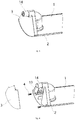
Fig. 2 is a structural schematic diagram of a longitudinal end of a first plate body in the air port component of the present disclosure; -
Fig. 3 is a structural schematic diagram of longitudinal ends after the first and second plate bodies in the air port component of the present disclosure are mounted; -
Fig. 4 is an exploded schematic diagram of longitudinal ends of plate bodies in the air port component of the present disclosure; -
Fig. 5 is a sectional view when the first and second plate bodies in the air port component of the present disclosure are in upper and lower alignment state prior to assembly; -
Fig. 6 is a sectional view after the first and second plate bodies in the air port component of the present disclosure are assembled; -
Fig. 7 is a side schematic diagram of the longitudinal ends of the plate bodies in the air port component of the present disclosure; and -
Fig. 8 is an enlarged drawing of a section D shown inFig. 7 . - The present disclosure is explained in detail below. In the following paragraphs, different aspects of the embodiments are defined in more detail. Various aspects so defined may be combined with any other one or more aspects, unless clearly indicated as not being combinable. In particular, any feature that is considered to be preferred or advantageous may be combined with one or more other features that are considered to be preferred or advantageous.
- The terms "first" and "second" appearing in the present disclosure are merely for the convenience of description, so as to distinguish different components having the same name, and do not indicate a sequential or primary-secondary relationship.
- In the description of the present disclosure, it should be understood that orientation or position relationships indicated by terms such as "upper", "lower", "left", "right", "front", "back", lateral" and "longitudinal" and the like are orientation or position relationships shown on the basis of the drawings, and are merely for the convenience of describing the present disclosure, rather than indicating or implying that the referred devices must have specific orientations or must be constructed and operated in specific orientations, and thus cannot be construed as limiting the protection scope of the present disclosure.
- The present disclosure relates to an air port component. Referring to
Fig. 1 to Fig. 8 , in a schematic embodiment, the air port component includes afirst plate body 1 and asecond plate body 2, and thefirst plate body 1 and thesecond plate body 2 are capable of being connected along the thickness direction through a snap-fit structure. Moreover, two longitudinal ends of thefirst plate body 1 are elastically connected with two longitudinal ends of thesecond plate body 2 respectively. Herein, the "longitudinal" is defined as the length direction of the plate body in the air port component, and "lateral" is defined as the width direction of the plate body in the air port component. - For example, in the condition that the air port component is mounded in an air conditioner, the air port component includes an air conditioner air deflector, the
first plate body 1 and thesecond plate body 2 jointly form an air deflector of the air conditioner, thefirst plate body 1 is an upper air deflector and faces to the interior of the air conditioner, and thesecond plate body 2 is a lower air deflector and faces to the exterior of the air conditioner. The following embodiments are described by taking it as an example that the air port component is applied to the air conditioner. Alternatively, thefirst plate body 1 and thesecond plate body 2 are blades of a louver structure. - In an embodiment of the air port component of the embodiment, in the case of a relatively large working environment temperature difference of the air conditioner, even if the difference between the linear expansion coefficients of materials of the two air deflectors is relatively large, the elastic deformation of the air deflectors due to temperature changes are compensated by the elastic deformation of an elastic component, so as to reduce the degree of plastic deformation of the air deflectors after a period of time, thereby improving the operation reliability of the air port component, preventing blockage during the operation, as well as ensuring that the airflow of the air outlet meets the design requirements to prevent condensation due to local overcooling, and also ensuring the aesthetic feeling of the appearance.
- In some embodiments, the air port component of the present disclosure further include an elastic component, and two longitudinal ends of the
first plate body 1 are elastically connected with two longitudinal ends of and thesecond plate body 2 through the elastic component. In the embodiments, there is no need to change the own structure of the upper second plate greatly, and it is easy to realize elastic connection. In the case of the air port component in the condition with a relatively large working environment temperature difference, even if the difference between the linear expansion coefficients of the materials used by the two plate bodies is relatively large, the elastic deformation of the plate bodies due to temperature changes would also be compensated by the elastic deformation of the elastic component. Alternatively, those skilled in the art would also manufacture the longitudinal ends of the plate bodies by using elastic materials, and thus the elastic component is omitted. - In the embodiment as shown in
Fig. 2 , the elastic component includes anelastic plate 13, and theelastic plate 13 is connected with the corresponding longitudinal ends of thefirst plate body 1 and thesecond plate body 2. - The
elastic plate 13 could be formed as following, theelastic plate 13 is disposed at a longitudinal end of one of thefirst plate body 1 and thesecond plate body 2 and is connected with a longitudinal end of the other of thefirst plate body 1 and thesecond plate body 2 in a state in which thefirst plate body 1 and thesecond plate body 2 are snapped. Alternatively, theelastic plate 13 is a separate structural member that is detachably connected with the corresponding longitudinal ends of thefirst plate body 1 and thesecond plate body 2 respectively. - The elasticity of the
elastic plate 13 are achieved by selecting an elastic material, and theelastic plate 13 are formed as an elastic structure. For example,elastic plates 13 would be disposed at the two longitudinal ends of the plate body, so as to compensate the deformation of the two longitudinal ends of the plate body due to temperature changes through the elastic deformation of theelastic plate 13. - The edges of the
first plate body 1 and thesecond plate body 2 are snapped along the longitudinal direction by a snap-fit structure, and the ends thereof are connected by theelastic plate 13. In the case of the air port component in a relatively large working environment temperature difference, even if the difference between the linear expansion coefficients of the materials used by the two plate bodies is relatively large, the deformation, particularly, extension or retraction of the plate bodies along the longitudinal direction, of the plate bodies due to temperature changes would also be compensated by the elastic deformation of the elastic component, so as to reduce the interaction force of the first and second plate bodies along the longitudinal direction, in this way, the degree of plastic deformation of the first and second plate bodies after a period of time is reduced, for example, the original radian of the entire plate body is ensured or the straightness of the plate body is maintained. Accordingly, the material selection of the first and second plate bodies is relatively wide, such as plastic, aluminum, titanium, or aluminum-magnesium alloy and the like. - The present disclosure reduces the degree of plastic deformation of the plate body, further, when applied to an air conditioner, this advantage would not only prevent blockage of the plate body during operation due to deformation, but also reduces abnormal noise generated by friction between the air deflector and the air conditioner main body, thereby improving the operation reliability of the air port component. In addition, it would also be ensured that the airflow at the air outlet of the air conditioner meets the design requirements to prevent condensation due to local overcooling, furthermore, the elastic plate disposed at the end of the air deflector also blocks cold air from entering between the first and second plate bodies, thus further improving the anti-condensation effect and preventing the occurrence of environmental health and safety issues. In addition, the aesthetic feeling of the appearance of the air conditioner would also be guaranteed, and the cost is reduced.
- Further, referring to
Fig. 7 , a first preset gap a exists at the connection between theelastic plate 13 and at least one of thefirst plate body 1 and thesecond plate body 2 along the longitudinal direction, and the first preset gap a is a gap that is reserved after the second plate body is assembled at the room temperature. By disposing the first preset gap a, compensation is be performed when theelastic plate 13 and the plate body detachably connected thereto approach to each other due to temperature changes, so as to reduce the possibility of plastic deformation of thefirst plate body 1 and thesecond plate body 2. Theelastic plate 13 is both connected to a structural member existing on the plate body, such as a snap-fit structure, or a structure for connecting theelastic plate 13 only may also be additionally disposed on the plate body. - In an embodiment as shown in
Fig. 4 , theelastic plate 13 is disposed on thefirst plate body 1, and theelastic plate 13 is detachably connected with thesecond plate body 2. In the structure in which thefirst plate body 1 is made of plastic and thesecond plate body 2 is made of an aluminum alloy, theelastic plate 13 and thefirst plate body 1 may be integrally formed by injection molding, so that the processing difficulty is reduced, and furthermore, there is a sufficient space for disposing theelastic plate 13 on thefirst plate body 1 facing to the interior of the air conditioner. - As shown in
Fig. 1 , the snap-fit structure between thefirst plate body 1 and thesecond plate body 2 are configured as follows. A first buckle group is disposed on one side of thefirst plate body 1 facing to thesecond plate body 2, a second buckle group is disposed on one side of thesecond plate body 2 facing to thefirst plate body 1, and the first buckle group and the second buckle group collectively forms the snap-fit structure. Theelastic plate 13 is disposed on thefirst plate body 1, and theelastic plate 13 is located on an outer side of the second buckle group along the longitudinal end and is connected to the end of the second buckle group in a state in which thefirst plate body 1 and thesecond plate body 2 are buckled through the first buckle group and the second buckle group. - Due to this arrangement, the second buckle group is used as a connecting structure to be connected with the
elastic plate 13, the existing structure on the plate body would be utilized, moreover, theelastic plate 13 is located on the outer side of the snap-fit structure along the longitudinal direction and cover the gap between the first and second plate bodies, and prevent cold air from entering into the gap to prevent condensation. - In this structure, a first preset gap a is disposed between the
elastic plate 13 and an outer end face of the second buckle group along the longitudinal direction. - In the embodiment in which the
elastic plate 13 is fixed to the outer side of the longitudinal end of the second buckle group, in the case of a relatively large working environment temperature difference, even if the difference between the linear expansion coefficients of the materials of the first and second plate bodies is relatively large, since theelastic plate 13 has elasticity, and the first preset gap a exists between theelastic plate 13 and the outer end face of the second buckle group, the elastic deformation of the plate bodies due to temperature changes is compensated, and the acting force between the first and second plate bodies in the case of the elastic deformation is reduced, thereby reducing the degree of plastic deformation of the first and second plate bodies, and then the strength of the entire air port component is ensured. - If the linear expansion coefficient of the material of the
second plate body 2 is less than the linear expansion coefficient of the material of thefirst plate body 1, when the environment temperature is relatively high, thefirst plate body 1 has a longitudinal elongation greater than that of thesecond plate body 2 since the linear expansion coefficient of the material is large. At this time, an upper end of theelastic plate 13 elastically deform outward, so that the deformation of the first and second plate bodies is minimized. When the environment temperature is relatively low, since thefirst plate body 1 has a large linear expansion coefficient of the material, the longitudinal amount of contraction of thefirst plate body 1 is greater than that of thesecond plate body 2. At this time, the first preset gap a is reduced, theelastic plate 13 elastically deform accordingly, in this way, even if thefirst plate body 1 contracts, it will not exert a large force on thesecond plate body 2 so as to minimize the deformation of the first and second plate bodies, thereby maintaining the original shape of the first and second plate bodies. - As shown in
Fig. 2 andFig. 4 , in order to fix thefirst plate body 1 and thesecond plate body 2 at the longitudinal ends, the air port component further includes afastener 4, and theelastic plate 13 and the longitudinal ends of the second buckle group are fixed through thefastener 4. Specifically, a mountinghole 131 is formed in theelastic plate 13, a threaded hole is formed in an outer end of the second buckle group along the longitudinal direction, and thefastener 4 such as a screw and the like is inserted into the mountinghole 131 and the threaded hole to achieve the fixation of theelastic plate 13 and the second buckle group. - During the pre-tightening of the
fastener 4, the first preset gap a exists between theelastic plate 13 and the outer end face of the second buckle group along the longitudinal direction by adjusting the torque on thefastener 4, instead of disposing a relatively large gap for the first and second plate bodies in the traditional pure buckle connection or glue bonding, and since the gap is formed in the inner side of theelastic plate 13, the cold air can be prevented from entering into the space between the first and second plate bodies to generate condensation. - Further, the elastic component includes an elastic spacer, the elastic spacer is located between the
elastic plate 13 and the second buckle group, that is, disposed in the first preset gap a, and the thickness of the elastic spacer is consistent with the first preset gap a for eliminating the first preset gap a. By disposing the elastic spacer, when thefastener 4 is installed, the first preset gap a is be adjusted relatively easily and accurately during the assembly. - In some embodiments, the elastic spacer is a rubber pad, the rubber pad is spaced between the
elastic plate 13 and the second buckle group, and the thickness of the rubber pad in a free state is consistent with the first preset gap a. Alternatively, the elastic spacer is also be a spring, the spring is disposed between theelastic plate 13 and the second buckle group, and the length of the spring in the free state is consistent with the first preset gap a. - A method for determining the first preset gap a is descried below. Referring to
Fig. 7 and Fig. 8 , theelastic plate 13 is fixed to thefirst plate body 1, and there is a first preset gap a between theelastic plate 13 and the outer end face of the second buckle group on thesecond plate body 2. - For example, the
first plate body 1 is an injection molding part, thesecond plate body 2 is an aluminum part or is made of a other lightweight high-strength materials, the coefficient A of thermal expansion of a plastic material is higher than the coefficient B of thermal expansion of an aluminum material, therefore, the coefficient A of thermal expansion of thefirst plate body 1 is higher than the coefficient B of thermal expansion of thesecond plate body 2. The first preset gap a = (L2-L1) / 2 = (L2 ∗ A ∗ ΔT-L1 ∗ B ∗ ΔT) + (E1 + E2), wherein:
L1 represents the distance between two sides of the two longitudinal ends of thesecond plate body 2 connected to the elastic component, and specifically, L1 represents the distance between the two outer sides of the second buckle group on thesecond plate body 2 along the longitudinal direction inFig.7 ; L2 represents the distance between inner sides of theelastic plates 13 at both ends of thefirst plate body 1; E1 represents an upper tolerance value of L1, and E2 represents a lower tolerance value of L2; A represents the coefficient of thermal expansion of thefirst plate body 1, B represents the coefficient of thermal expansion of thesecond plate body 2, and A> B; and ΔT represents an environment temperature difference of the air conditioner. - In order to further prevent cold air from entering the air port component, the air port component includes a
cover plate 3, thecover plate 3 is disposed on the outer side of theelastic plate 13 along the longitudinal direction of an air conditioner wind deflector, so as to seal the gap at the longitudinal ends of thefirst plate body 1 and thesecond plate body 2, so as to achieve a better anti-condensation effect. As shown inFig. 4 , the base end part of thesecond plate body 2 has an extended end relative to the longitudinal end of the second buckle group, the length of the extended end is greater than the total thickness of theelastic plate 13 and thecover plate 3,Fig. 3 shows a structural schematic diagram of thecover plate 3 after installation, even if the amount of contraction of thesecond plate body 2 is relatively large due to environment temperature changes, since the end of thesecond plate body 2 exceeds the outer side face of thecover plate 3, a gap between thesecond plate body 2 and thecover plate 3 is avoided, whic not only prevents the cold air from entering the air deflector device, but also ensures the aesthetic feeling of the appearance of the front face of the air conditioner. - Further, as shown in
Fig. 5 , the air port component further includes aflexible pad 5, such as sponge or rubber or the like, theflexible pad 5 is disposed between thefirst plate body 1 and thesecond plate body 2, there is a second preset gap b at the connection of the first buckle group and the second buckle group, and theflexible pad 5 is filled in the second preset gap b. Because theflexible pad 5 is soft and large in compression amount, so the deformation of the first buckle group and the second buckle group due to environment temperature changes is alleviated, thereby avoiding abnormal noise; and furthermore, an effective connection is formed between the first and second plate bodies, so that the plate bodies extend or contract in the longitudinal and lateral directions. - A specific arrangement form of the first buckle group and the second buckle group is given below, as shown in
Fig. 1 , the first buckle group includes two groups offirst buckle structures 1 disposed on two longitudinal edges of thefirst plate body 1 respectively, and each group offirst buckle structures 11 includes a plurality offirst buckle structures 11 disposed at internals along the longitudinal direction of thefirst plate body 1. For example, the plurality offirst buckle structures 11 in each group offirst buckle structures 11 are evenly spaced, and an enlarged drawing B inFig. 1 shows the shape of a singlefirst buckle structure 11. The second buckle group includes two groups ofsecond buckle structures 21 disposed at the two lateral ends of thesecond plate body 1 respectively, and each group ofsecond buckle structures 21 includes strip-shaped buckles extending along the longitudinal direction of thesecond plate body 2. - Specifically, in the sectional view of the first and second plate bodies as shown in
Fig. 5 prior to assembly, the section of eachfirst buckle structure 11 is a hook-shaped structure with an outward free end, thesecond plate body 2 has an arc-shaped structure, the section of each strip-shaped buckle is a clamping structure with irregular section, when thefirst plate body 1 pressed downward aligning thesecond plate body 2, thesecond plate body 2 generates elastic deformation along the lateral direction, the distance between two strip-shaped buckles is increased, so that eachfirst buckle structure 11 is located on the inner side of the strip-shaped buckle, and after thefirst plate body 1 is released, eachfirst buckle structure 11 is clamped with the corresponding strip-shaped buckle. Referring to an enlarged drawing C inFig. 6 , thefirst buckle structure 11 and asecond buckle structure 21 have a second preset gap b in the height direction, and the second preset gap b is filled by theflexible pad 5 disposed between the upper second plate bodies. - It can be seen from
Fig. 5 that, due to the asymmetric structure of the first and second plate bodies at both ends along the lateral direction, and the difference between the two ends of thesecond plate body 2 along the lateral direction is relative small, it is not easy to be clearly recognized by a user during assembly, so an error prevention structure is be additionally disposed on the first and second plate bodies to ensure a correct mounting direction of the first and second plate bodies. Specifically, afirst guide structure 12 is disposed on one side of thefirst plate body 1 facing to thesecond plate body 2, and thefirst guide structure 12 is located between the two groups offirst buckle structures 11 in the lateral direction; and asecond guide structure 22 is disposed on one side of thesecond plate body 2 facing to thefirst plate body 1, and thesecond guide structure 22 is located between the two groups ofsecond buckle structures 21 in the lateral direction. Thefirst guide structure 12 and thesecond guide structure 22 are spaced differently relative to the lateral center positions of thefirst plate body 1 and thesecond plate body 2, that is, the distance L3 between the first guide structure and one lateral end of the guide plate is unequal to the distance L4 between the second guide structure and other lateral end of the guide plate, correct installation is be achieved when thefirst plate body 1 and thesecond plate body 2 are correctly mounted, and correct installation cannot be achieved when the mounting direction of thefirst plate body 1 and thesecond plate body 2 is wrong. - Further, the
first guide structure 12 and thesecond guide structure 22 have different height, and thus form a complementary structure, which prevents the first guide structure and the second guide structure from cooperating in place when thefirst plate body 1 and thesecond plate body 2 are incorrectly mounted. - It can be seen from
Fig. 1 that, thefirst guide structure 12 includes two frame-shaped protrusion, a partition plate is arranged in the middle of the rectangular frame protrusion along the longitudinal direction of the plate body, as shown in an enlarged view A inFig. 1 , the two frame-shaped protrusion are respectively disposed close to the longitudinal ends of thefirst plate body 1. Thesecond guide structure 22 includes two strip-shaped protrusions, the strip-shaped protrusions extend along the longitudinal direction of thesecond plate body 2, and the two strip-shaped protrusions are located between the two groups ofsecond buckle structures 21 and spaced differently relative to the center of thesecond plate body 2 along the lateral direction. - Referring to
Fig. 6 , the two strip-shaped protrusion have different heights, the left side protrusion is higher than the right side protrusion, correspondingly, two side plates of each frame-shaped protrusion also has a height difference along the lateral direction, but the protrusion height of the left side plate of the frame-shaped protrusion is lower than that of the right side plate. After the first and second plate bodies is mounted in place, the two frame-shaped protrusions is embedded between the two strip-shaped protrusion, if the mounting direction is wrong, the height difference of the guide structures will block the two plate bodies to be mounted in place. Since thesecond plate body 2 is circular arc-shaped between the two strip-shaped protrusions, correspondingly, the top of the frame-shaped protrusion is designed as mating circular arc shapes, after the two plate bodies are mounted in place, a relatively small gap is retained between the two circular arc surfaces of the first and second plate bodies, so that the snap-fit structure is mounted in place. - Further, the
first guide structure 12 is higher than the first buckle group, so that it cannot be assembled in place even in the case of reverse installation, or the snap-fit structure is not damaged even if forced by external force, so as to reduce assembly errors during the production. - In order to realize the movement of the air deflector to adjust the size of the air outlet of the air conditioner, as shown in
Fig. 2 , thefirst plate body 1 is provided with a drivingmember mounting interface 14 for mounting a driving member capable of driving thefirst plate body 1 and thesecond plate body 2. The drivingmember mounting interface 14 is disposed on thefirst plate body 1, when thefirst plate body 1 is made of plastic, it is convenient to be integrally formed with thefirst plate body 1 by injection molding to reduce processing difficulty; and it plays a mutual reinforcement role with theelastic plate 13 to ensure the strength of the structure, so that the driving member stably and accurately drives the air deflector device. In addition, compared with the structure in which the drivingmember mounting interface 14 is disposed on thesecond plate body 2, there is need to form an opening for enabling a power output shaft of the driving member to pass through in thefirst plate body 1 in this driving manner, and the strength of thefirst plate body 1 is ensured. - Specifically, still referring to
Fig. 2 , the longitudinal end of thefirst plate body 1 is configured as a supporting structure that arches away from thesecond plate body 2, the supporting structure is provided withinclined side plates 15 on both sides along the lateral direction of thefirst plate body 1 respectively, the bottom ends of the twoside plates 15 are connected with thefirst plate body 1, the drivingmember mounting interface 14 is disposed at a position where the top ends meet, and the axial line of the drivingmember mounting interface 14 is consistent with the longitudinal direction of thefirst plate body 1. Twoelastic plate 13 are respectively fixed to the two ends of the twoside plates 15, and the twoelastic plates 13 are spaced apart. - When the air conditioner air deflector device of the present disclosure is assembled, as shown in
Fig. 5 , thesecond plate body 2 is placed below, and the entire sponge is pasted on the inner side of thesecond plate body 2, and meanwhile the sponge covers the second buckle group; due to the error prevention structure, thefirst plate body 1 is placed above thesecond plate body 2 in the correct direction, and thefirst plate body 1 is pressed down, and by means of the guide of thefirst guide structure 12 and thesecond guide structure 22, the distance between the two air deflectors is reduced, until the first buckle group and the second buckle group are buckled in place. Finally, as shown inFig. 4 , theelastic plate 13 and thesecond plate body 2 are fixed by thefastener 4. - In addition, the present disclosure further relates to an air conditioner, including the air port component described in the above embodiment. Since such an air deflector device is not easily deformed when the environment temperature changes greatly, the air conditioner of the present disclosure at least has one of the following advantages:
- it improves the air guide reliability of the air conditioner, and it is not easy to get stuck;
- when the air conditioner works, the noise of mutual friction between the air deflector device and the main structure is small; and
- the airflow design of the air outlet of the air conditioner meets the design requirements, which prevents condensation due to local overcooling, thereby improving the working performance of the air conditioner.
- The air port component and the air conditioner provided by the present disclosure have been described in detail above. Specific embodiments are used herein to explain the principles and implementations of the present disclosure. The descriptions of the above embodiments are only used to help to understand the methods and core ideas of the present disclosure. It should be noted that, for those of ordinary skill in the art, without departing from the principles of the present disclosure, several improvements and modifications may be made to the present disclosure, and these improvements and modifications also fall within the protection scope of the claims of the present disclosure.
Claims (19)
- An air port component, comprising a first plate body (1) and a second plate body (2), wherein two longitudinal ends of the first plate body (1) are elastically connected with two longitudinal ends of the second plate body (2) respectively.
- The air port component as claimed in claim 1, further comprising an elastic component, wherein the two longitudinal ends of the first plate body (1) are elastically connected with the two longitudinal ends of the second plate body (2) respectively through the elastic components.
- The air port component as claimed in claim 2, wherein the elastic component comprises an elastic plate (13), and the elastic plate (13) is connected to the longitudinal ends of the first plate body (1) and the second plate body (2).
- The air port component as claimed in claim 3, wherein a first preset gap (a) exists at the connection of the elastic plate (13) and at least one of the first plate body (1) and the second plate body (2) along the longitudinal direction.
- The air port component as claimed in claim 4, wherein the elastic component further comprises an elastic spacer, and the elastic spacer is disposed in the first preset gap (a).
- The air port component as claimed in claim 5, wherein the elastic spacer comprises a rubber pad, and the thickness of the rubber pad in a free state is consistent with the first preset gap (a); or the elastic spacer comprises a spring, and the height of the spring in the free state is consistent with the first preset gap (a).
- The air port component as claimed in claim 3, wherein the elastic plate (13) is disposed on the first plate body (1), and the elastic plate (13) and the second plate body (12) are detachably connected.
- The air port component as claimed in claim 7, wherein a first buckle group is disposed on one side of the first plate body (1) facing to the second plate body (2), a second buckle group is disposed on one side of the second plate body (2) facing to the first plate body (1), the first buckle group is snapped with the second buckle group, and the elastic plate (13) is located at an outer side of the longitudinal end of the second buckle group and is connected with an end of the second buckle group.
- The air port component as claimed in claim 8, further comprising a fastener (4), wherein the elastic plate (13) is connected to a longitudinal end of the second buckle group through the fastener (4).
- The air port component as claimed in claim 8, wherein a first preset gap (a) exists between the elastic plate (13) and an outer end of the second buckle group along the longitudinal direction.
- The air port component as claimed in claim 8, further comprising a flexible pad (5), wherein a second preset gap (b) exists at a site on which the first buckle group matches the second buckle group, and the flexible pad (5) is disposed between the first plate body (1) and the second plate body (2) and is filled in the second preset gap (b).
- The air port component as claimed in claim 8, wherein the first buckle group comprises two groups of first buckle structures (11) disposed at two lateral ends of the first plate body (1) respectively, and each group of first buckle structures (11) comprises a plurality of first buckle structures (11) disposed at intervals along the longitudinal direction of the first plate body (1); and
the second buckle group comprises two groups of second buckle structures (21) disposed at two lateral ends of the second plate body (2) respectively, and each group of second buckle structures (21) comprises strip-shaped buckles extending along the longitudinal direction of the second plate body (2), and the first buckle structures (11) match with the strip-shaped buckles correspondingly. - The air port component as claimed in claim 1, wherein a driving member mounting interface (14) is disposed on the first plate body (1), so as to mount a driving member capable of driving the first plate body (1) and the second plate body (2).
- The air port component as claimed in claim 1, further comprising a cover plate (3), wherein the cove plate (3) is arranged on the outer side of the elastic component, so as to seal a gap on the longitudinal ends of the first plate body (1) and the second plate body (2).
- The air port component as claimed in claim 1, wherein a first guide structure (12) is disposed on one side of the first plate body (1) facing to the second plate body (2), a second guide structure (22) is disposed on one side of the second plate body (2) facing to the first plate body (1), the first guide structure (12) and the second guide structure (22) are spaced differently relative to a lateral centerline of the air port component, and are installed in place when the first plate body (1) and the second plate body (2) are correctly mounted.
- The air port component as claimed in claim 15, wherein the first guide structure (12) and the second guide structure (22) have different heights to form a complementary structure, preventing the first guide structure (12) and the second guide structure (22) from installing in place when the first plate body (1) and the second plate body (2) are incorrectly mounted.
- The air port component as claimed in claim 15, wherein a first buckle group is disposed on one side of the first plate body (1) facing to the second plate body (2), and the first guide structure (12) is higher than the first buckle group.
- The air port component as claimed in claim 4, wherein the elastic plate (13) is disposed on the first plate body (1), and the first preset gap a = (L2 ∗ A ∗ ΔT-L1 ∗ B ∗ ΔT) + (E1 + E2), wherein,
L1 represents a distance between two sides of the two longitudinal ends of the second plate body (2) connected by the elastic component;
L2 represents a distance between two inner sides of the elastic plates (13) at both ends of the first plate body (1);
E1 represents an upper tolerance value of L1, and E2 represents a lower tolerance value of L2;
A represents the coefficient of thermal expansion of the first plate body (1), B represents the coefficient of thermal expansion of the second plate body (2), and A> B; and
ΔT represents an environment temperature difference in which the air conditioner is located. - An air conditioner, comprising the air port component as claimed in claim 1.
Applications Claiming Priority (3)
| Application Number | Priority Date | Filing Date | Title |
|---|---|---|---|
| CN201710504254 | 2017-06-28 | ||
| CN201711401630.XA CN108006930B (en) | 2017-06-28 | 2017-12-22 | Tuyere member and air conditioner |
| PCT/CN2018/102281 WO2019119849A1 (en) | 2017-06-28 | 2018-08-24 | Wind port component and air conditioner |
Publications (3)
| Publication Number | Publication Date |
|---|---|
| EP3640560A1 true EP3640560A1 (en) | 2020-04-22 |
| EP3640560A4 EP3640560A4 (en) | 2020-07-15 |
| EP3640560B1 EP3640560B1 (en) | 2023-04-12 |
Family
ID=61942140
Family Applications (1)
| Application Number | Title | Priority Date | Filing Date |
|---|---|---|---|
| EP18891740.5A Active EP3640560B1 (en) | 2017-06-28 | 2018-08-24 | Wind port component and air conditioner |
Country Status (5)
| Country | Link |
|---|---|
| US (1) | US11333391B2 (en) |
| EP (1) | EP3640560B1 (en) |
| CN (4) | CN107940719B (en) |
| ES (1) | ES2949515T3 (en) |
| WO (1) | WO2019119849A1 (en) |
Families Citing this family (7)
| Publication number | Priority date | Publication date | Assignee | Title |
|---|---|---|---|---|
| CN107940719B (en) | 2017-06-28 | 2024-04-19 | 珠海格力电器股份有限公司 | Tuyere member and air conditioner |
| CN109297090A (en) * | 2018-11-19 | 2019-02-01 | 宁波奥克斯电气股份有限公司 | A duct machine, air conditioner and electric control box |
| CN111351137A (en) * | 2020-04-10 | 2020-06-30 | 青岛海尔空调器有限总公司 | An air conditioner indoor unit |
| CN112361571B (en) * | 2020-11-10 | 2021-10-01 | 珠海格力电器股份有限公司 | A wind deflector assembly, indoor unit and air conditioner |
| CN116067000A (en) * | 2021-10-29 | 2023-05-05 | 青岛海尔空调器有限总公司 | Air deflector assembly, method and system for controlling air deflector assembly |
| CN114211939B (en) * | 2021-11-15 | 2023-02-24 | 南京塔塔汽车零部件系统有限公司 | Air guide structure of automobile air outlet, automobile air outlet and automobile |
| CN118532812B (en) * | 2024-07-25 | 2024-11-12 | 靖江市瑞风空调通风设备厂 | An air vent that is easy to assemble |
Family Cites Families (25)
| Publication number | Priority date | Publication date | Assignee | Title |
|---|---|---|---|---|
| JP3058988B2 (en) * | 1992-06-01 | 2000-07-04 | 三菱重工業株式会社 | Resin panel for air conditioner |
| JP3885845B2 (en) * | 1998-03-16 | 2007-02-28 | 株式会社富士通ゼネラル | Air conditioner |
| CN2513310Y (en) * | 2001-10-04 | 2002-09-25 | 姜牧 | TV wall unit with flexible structure |
| JP4141369B2 (en) * | 2003-10-17 | 2008-08-27 | シャープ株式会社 | Wind direction plate and air conditioner |
| CN2663863Y (en) * | 2003-11-08 | 2004-12-15 | 海尔集团公司 | Air conditioner having novel guide vane fixing structure |
| DE102005037156A1 (en) * | 2005-08-06 | 2007-02-08 | Daimlerchrysler Ag | heat exchangers |
| JP2007187405A (en) | 2006-01-16 | 2007-07-26 | Matsushita Electric Ind Co Ltd | Air conditioner |
| JP2008281303A (en) | 2007-05-14 | 2008-11-20 | Panasonic Corp | Air conditioner |
| CN201059719Y (en) | 2007-07-31 | 2008-05-14 | 广东志高空调有限公司 | Structure for connecting panel with middle frame of air conditioner |
| KR20100027305A (en) * | 2008-09-02 | 2010-03-11 | 삼성전자주식회사 | Air conditioner |
| CN103363642B (en) * | 2012-04-01 | 2016-04-20 | 珠海格力电器股份有限公司 | Air deflector and air conditioner with same |
| CN202547036U (en) | 2012-04-01 | 2012-11-21 | 珠海格力电器股份有限公司 | Air deflector of air conditioner and air conditioner with same |
| CN103363640B (en) * | 2012-04-01 | 2015-10-28 | 珠海格力电器股份有限公司 | Air deflector of air conditioner and air conditioner with same |
| CN203215932U (en) * | 2013-04-28 | 2013-09-25 | 珠海格力电器股份有限公司 | Air deflector assembly and air conditioner with same |
| CN104121675A (en) | 2013-04-28 | 2014-10-29 | 珠海格力电器股份有限公司 | Air deflector assembly and air conditioner with same |
| CN104848511A (en) * | 2014-02-17 | 2015-08-19 | 珠海格力电器股份有限公司 | Air deflector device |
| JP6618243B2 (en) | 2014-06-17 | 2019-12-11 | 株式会社京都プラテック | Air conditioner louver |
| CN204830388U (en) * | 2015-03-17 | 2015-12-02 | 广东美的制冷设备有限公司 | Aviation baffle and air conditioner |
| JP2017096560A (en) * | 2015-11-25 | 2017-06-01 | 株式会社京都プラテック | Louver of air conditioner |
| CN106123267A (en) * | 2016-06-21 | 2016-11-16 | 珠海格力电器股份有限公司 | Double-layer air deflector, air conditioner and preparation method of double-layer air deflector |
| CN106123271B (en) * | 2016-09-05 | 2022-07-05 | 珠海格力电器股份有限公司 | Air deflector matching structure and air conditioner |
| CN206094474U (en) * | 2016-10-08 | 2017-04-12 | 珠海格力电器股份有限公司 | Air deflector and air conditioner with same |
| CN106288271B (en) * | 2016-10-08 | 2021-12-31 | 珠海格力电器股份有限公司 | Air deflector and air conditioner with same |
| CN107940719B (en) * | 2017-06-28 | 2024-04-19 | 珠海格力电器股份有限公司 | Tuyere member and air conditioner |
| CN107421090B (en) | 2017-08-02 | 2024-04-02 | 珠海格力电器股份有限公司 | Air deflector assembly and air conditioner with same |
-
2017
- 2017-12-22 CN CN201711401399.4A patent/CN107940719B/en active Active
- 2017-12-22 CN CN201721812251.5U patent/CN207815653U/en not_active Withdrawn - After Issue
- 2017-12-22 CN CN201721812329.3U patent/CN207815654U/en active Active
- 2017-12-22 CN CN201711401630.XA patent/CN108006930B/en active Active
-
2018
- 2018-08-24 US US16/649,786 patent/US11333391B2/en active Active
- 2018-08-24 EP EP18891740.5A patent/EP3640560B1/en active Active
- 2018-08-24 ES ES18891740T patent/ES2949515T3/en active Active
- 2018-08-24 WO PCT/CN2018/102281 patent/WO2019119849A1/en not_active Ceased
Also Published As
| Publication number | Publication date |
|---|---|
| CN108006930B (en) | 2023-11-10 |
| CN207815654U (en) | 2018-09-04 |
| EP3640560A4 (en) | 2020-07-15 |
| CN108006930A (en) | 2018-05-08 |
| WO2019119849A1 (en) | 2019-06-27 |
| US11333391B2 (en) | 2022-05-17 |
| CN107940719A (en) | 2018-04-20 |
| ES2949515T3 (en) | 2023-09-29 |
| CN107940719B (en) | 2024-04-19 |
| EP3640560B1 (en) | 2023-04-12 |
| CN207815653U (en) | 2018-09-04 |
| US20200278131A1 (en) | 2020-09-03 |
Similar Documents
| Publication | Publication Date | Title |
|---|---|---|
| US11333391B2 (en) | Air port component and air conditioner | |
| US9144165B2 (en) | Housing structure and electronic device using the same | |
| CN216842531U (en) | Corner connecting structure and air conditioner box body adopting same | |
| CN106403233A (en) | Door body assembly and cabinet air conditioner | |
| EP2725447B1 (en) | Electronic device and electronic device manufacturing method | |
| CN210348334U (en) | Hard disk bracket | |
| CN106353907A (en) | Liquid crystal display device | |
| CN106322708A (en) | Air conditioner air outlet structure, installation method and air conditioner | |
| WO2022205871A1 (en) | Cabinet-type air conditioner indoor unit and cabinet-type air conditioner | |
| CN108036493A (en) | The casing assembly and air conditioner of air conditioner | |
| US20150211286A1 (en) | Arrangement and method for retrofitting glass wall panel system with glass wall panel | |
| CN111755273B (en) | Key adjustment mechanism and electronic device | |
| JP4450325B2 (en) | Joinery | |
| CN110029756B (en) | Modular frame system | |
| CN111119669B (en) | Window systems | |
| CN220692476U (en) | Mounting device for angular space | |
| CN223691254U (en) | Display box assembly and air conditioner | |
| CN216114634U (en) | Panel assembly of air conditioner and air conditioner | |
| CN218957092U (en) | Rotary mounting bracket for display screen assembly and related device thereof | |
| CN218439114U (en) | Novel inwardly opened window structure | |
| EP3517852A1 (en) | Diffuser for air conditioning installations | |
| CN215827178U (en) | Assembled sealing structure | |
| JP6986975B2 (en) | Glass door for showcase | |
| EP3568707B1 (en) | Enclosure assembly and metering apparatus comprising same | |
| CN223054376U (en) | Shower door glass panel assembly |
Legal Events
| Date | Code | Title | Description |
|---|---|---|---|
| STAA | Information on the status of an ep patent application or granted ep patent |
Free format text: STATUS: THE INTERNATIONAL PUBLICATION HAS BEEN MADE |
|
| PUAI | Public reference made under article 153(3) epc to a published international application that has entered the european phase |
Free format text: ORIGINAL CODE: 0009012 |
|
| STAA | Information on the status of an ep patent application or granted ep patent |
Free format text: STATUS: REQUEST FOR EXAMINATION WAS MADE |
|
| 17P | Request for examination filed |
Effective date: 20200117 |
|
| AK | Designated contracting states |
Kind code of ref document: A1 Designated state(s): AL AT BE BG CH CY CZ DE DK EE ES FI FR GB GR HR HU IE IS IT LI LT LU LV MC MK MT NL NO PL PT RO RS SE SI SK SM TR |
|
| AX | Request for extension of the european patent |
Extension state: BA ME |
|
| A4 | Supplementary search report drawn up and despatched |
Effective date: 20200615 |
|
| RIC1 | Information provided on ipc code assigned before grant |
Ipc: F24F 13/22 20060101ALI20200608BHEP Ipc: F24F 13/08 20060101AFI20200608BHEP Ipc: F24F 1/0011 20190101ALI20200608BHEP Ipc: F24F 13/14 20060101ALI20200608BHEP |
|
| DAV | Request for validation of the european patent (deleted) | ||
| DAX | Request for extension of the european patent (deleted) | ||
| GRAP | Despatch of communication of intention to grant a patent |
Free format text: ORIGINAL CODE: EPIDOSNIGR1 |
|
| STAA | Information on the status of an ep patent application or granted ep patent |
Free format text: STATUS: GRANT OF PATENT IS INTENDED |
|
| RIC1 | Information provided on ipc code assigned before grant |
Ipc: F24F 13/14 20060101ALI20221107BHEP Ipc: F24F 1/0011 20190101ALI20221107BHEP Ipc: F24F 13/22 20060101ALI20221107BHEP Ipc: F24F 13/08 20060101AFI20221107BHEP |
|
| INTG | Intention to grant announced |
Effective date: 20221130 |
|
| GRAS | Grant fee paid |
Free format text: ORIGINAL CODE: EPIDOSNIGR3 |
|
| GRAA | (expected) grant |
Free format text: ORIGINAL CODE: 0009210 |
|
| STAA | Information on the status of an ep patent application or granted ep patent |
Free format text: STATUS: THE PATENT HAS BEEN GRANTED |
|
| AK | Designated contracting states |
Kind code of ref document: B1 Designated state(s): AL AT BE BG CH CY CZ DE DK EE ES FI FR GB GR HR HU IE IS IT LI LT LU LV MC MK MT NL NO PL PT RO RS SE SI SK SM TR |
|
| REG | Reference to a national code |
Ref country code: GB Ref legal event code: FG4D |
|
| REG | Reference to a national code |
Ref country code: CH Ref legal event code: EP |
|
| REG | Reference to a national code |
Ref country code: DE Ref legal event code: R096 Ref document number: 602018048445 Country of ref document: DE |
|
| REG | Reference to a national code |
Ref country code: IE Ref legal event code: FG4D |
|
| REG | Reference to a national code |
Ref country code: AT Ref legal event code: REF Ref document number: 1559991 Country of ref document: AT Kind code of ref document: T Effective date: 20230515 |
|
| P01 | Opt-out of the competence of the unified patent court (upc) registered |
Effective date: 20230530 |
|
| REG | Reference to a national code |
Ref country code: LT Ref legal event code: MG9D |
|
| REG | Reference to a national code |
Ref country code: NL Ref legal event code: MP Effective date: 20230412 |
|
| REG | Reference to a national code |
Ref country code: AT Ref legal event code: MK05 Ref document number: 1559991 Country of ref document: AT Kind code of ref document: T Effective date: 20230412 |
|
| PG25 | Lapsed in a contracting state [announced via postgrant information from national office to epo] |
Ref country code: NL Free format text: LAPSE BECAUSE OF FAILURE TO SUBMIT A TRANSLATION OF THE DESCRIPTION OR TO PAY THE FEE WITHIN THE PRESCRIBED TIME-LIMIT Effective date: 20230412 |
|
| REG | Reference to a national code |
Ref country code: ES Ref legal event code: FG2A Ref document number: 2949515 Country of ref document: ES Kind code of ref document: T3 Effective date: 20230929 |
|
| PG25 | Lapsed in a contracting state [announced via postgrant information from national office to epo] |
Ref country code: SE Free format text: LAPSE BECAUSE OF FAILURE TO SUBMIT A TRANSLATION OF THE DESCRIPTION OR TO PAY THE FEE WITHIN THE PRESCRIBED TIME-LIMIT Effective date: 20230412 Ref country code: PT Free format text: LAPSE BECAUSE OF FAILURE TO SUBMIT A TRANSLATION OF THE DESCRIPTION OR TO PAY THE FEE WITHIN THE PRESCRIBED TIME-LIMIT Effective date: 20230814 Ref country code: NO Free format text: LAPSE BECAUSE OF FAILURE TO SUBMIT A TRANSLATION OF THE DESCRIPTION OR TO PAY THE FEE WITHIN THE PRESCRIBED TIME-LIMIT Effective date: 20230712 Ref country code: AT Free format text: LAPSE BECAUSE OF FAILURE TO SUBMIT A TRANSLATION OF THE DESCRIPTION OR TO PAY THE FEE WITHIN THE PRESCRIBED TIME-LIMIT Effective date: 20230412 |
|
| PG25 | Lapsed in a contracting state [announced via postgrant information from national office to epo] |
Ref country code: RS Free format text: LAPSE BECAUSE OF FAILURE TO SUBMIT A TRANSLATION OF THE DESCRIPTION OR TO PAY THE FEE WITHIN THE PRESCRIBED TIME-LIMIT Effective date: 20230412 Ref country code: PL Free format text: LAPSE BECAUSE OF FAILURE TO SUBMIT A TRANSLATION OF THE DESCRIPTION OR TO PAY THE FEE WITHIN THE PRESCRIBED TIME-LIMIT Effective date: 20230412 Ref country code: LV Free format text: LAPSE BECAUSE OF FAILURE TO SUBMIT A TRANSLATION OF THE DESCRIPTION OR TO PAY THE FEE WITHIN THE PRESCRIBED TIME-LIMIT Effective date: 20230412 Ref country code: LT Free format text: LAPSE BECAUSE OF FAILURE TO SUBMIT A TRANSLATION OF THE DESCRIPTION OR TO PAY THE FEE WITHIN THE PRESCRIBED TIME-LIMIT Effective date: 20230412 Ref country code: IS Free format text: LAPSE BECAUSE OF FAILURE TO SUBMIT A TRANSLATION OF THE DESCRIPTION OR TO PAY THE FEE WITHIN THE PRESCRIBED TIME-LIMIT Effective date: 20230812 Ref country code: HR Free format text: LAPSE BECAUSE OF FAILURE TO SUBMIT A TRANSLATION OF THE DESCRIPTION OR TO PAY THE FEE WITHIN THE PRESCRIBED TIME-LIMIT Effective date: 20230412 Ref country code: GR Free format text: LAPSE BECAUSE OF FAILURE TO SUBMIT A TRANSLATION OF THE DESCRIPTION OR TO PAY THE FEE WITHIN THE PRESCRIBED TIME-LIMIT Effective date: 20230713 Ref country code: AL Free format text: LAPSE BECAUSE OF FAILURE TO SUBMIT A TRANSLATION OF THE DESCRIPTION OR TO PAY THE FEE WITHIN THE PRESCRIBED TIME-LIMIT Effective date: 20230412 |
|
| PG25 | Lapsed in a contracting state [announced via postgrant information from national office to epo] |
Ref country code: FI Free format text: LAPSE BECAUSE OF FAILURE TO SUBMIT A TRANSLATION OF THE DESCRIPTION OR TO PAY THE FEE WITHIN THE PRESCRIBED TIME-LIMIT Effective date: 20230412 |
|
| REG | Reference to a national code |
Ref country code: DE Ref legal event code: R097 Ref document number: 602018048445 Country of ref document: DE |
|
| PG25 | Lapsed in a contracting state [announced via postgrant information from national office to epo] |
Ref country code: SK Free format text: LAPSE BECAUSE OF FAILURE TO SUBMIT A TRANSLATION OF THE DESCRIPTION OR TO PAY THE FEE WITHIN THE PRESCRIBED TIME-LIMIT Effective date: 20230412 |
|
| PG25 | Lapsed in a contracting state [announced via postgrant information from national office to epo] |
Ref country code: SM Free format text: LAPSE BECAUSE OF FAILURE TO SUBMIT A TRANSLATION OF THE DESCRIPTION OR TO PAY THE FEE WITHIN THE PRESCRIBED TIME-LIMIT Effective date: 20230412 Ref country code: SK Free format text: LAPSE BECAUSE OF FAILURE TO SUBMIT A TRANSLATION OF THE DESCRIPTION OR TO PAY THE FEE WITHIN THE PRESCRIBED TIME-LIMIT Effective date: 20230412 Ref country code: RO Free format text: LAPSE BECAUSE OF FAILURE TO SUBMIT A TRANSLATION OF THE DESCRIPTION OR TO PAY THE FEE WITHIN THE PRESCRIBED TIME-LIMIT Effective date: 20230412 Ref country code: EE Free format text: LAPSE BECAUSE OF FAILURE TO SUBMIT A TRANSLATION OF THE DESCRIPTION OR TO PAY THE FEE WITHIN THE PRESCRIBED TIME-LIMIT Effective date: 20230412 Ref country code: DK Free format text: LAPSE BECAUSE OF FAILURE TO SUBMIT A TRANSLATION OF THE DESCRIPTION OR TO PAY THE FEE WITHIN THE PRESCRIBED TIME-LIMIT Effective date: 20230412 Ref country code: CZ Free format text: LAPSE BECAUSE OF FAILURE TO SUBMIT A TRANSLATION OF THE DESCRIPTION OR TO PAY THE FEE WITHIN THE PRESCRIBED TIME-LIMIT Effective date: 20230412 |
|
| PLBE | No opposition filed within time limit |
Free format text: ORIGINAL CODE: 0009261 |
|
| STAA | Information on the status of an ep patent application or granted ep patent |
Free format text: STATUS: NO OPPOSITION FILED WITHIN TIME LIMIT |
|
| PG25 | Lapsed in a contracting state [announced via postgrant information from national office to epo] |
Ref country code: MC Free format text: LAPSE BECAUSE OF FAILURE TO SUBMIT A TRANSLATION OF THE DESCRIPTION OR TO PAY THE FEE WITHIN THE PRESCRIBED TIME-LIMIT Effective date: 20230412 |
|
| 26N | No opposition filed |
Effective date: 20240115 |
|
| REG | Reference to a national code |
Ref country code: CH Ref legal event code: PL |
|
| PG25 | Lapsed in a contracting state [announced via postgrant information from national office to epo] |
Ref country code: MC Free format text: LAPSE BECAUSE OF FAILURE TO SUBMIT A TRANSLATION OF THE DESCRIPTION OR TO PAY THE FEE WITHIN THE PRESCRIBED TIME-LIMIT Effective date: 20230412 |
|
| PG25 | Lapsed in a contracting state [announced via postgrant information from national office to epo] |
Ref country code: LU Free format text: LAPSE BECAUSE OF NON-PAYMENT OF DUE FEES Effective date: 20230824 |
|
| PG25 | Lapsed in a contracting state [announced via postgrant information from national office to epo] |
Ref country code: LU Free format text: LAPSE BECAUSE OF NON-PAYMENT OF DUE FEES Effective date: 20230824 Ref country code: CH Free format text: LAPSE BECAUSE OF NON-PAYMENT OF DUE FEES Effective date: 20230831 |
|
| PG25 | Lapsed in a contracting state [announced via postgrant information from national office to epo] |
Ref country code: SI Free format text: LAPSE BECAUSE OF FAILURE TO SUBMIT A TRANSLATION OF THE DESCRIPTION OR TO PAY THE FEE WITHIN THE PRESCRIBED TIME-LIMIT Effective date: 20230412 |
|
| REG | Reference to a national code |
Ref country code: BE Ref legal event code: MM Effective date: 20230831 |
|
| REG | Reference to a national code |
Ref country code: IE Ref legal event code: MM4A |
|
| PG25 | Lapsed in a contracting state [announced via postgrant information from national office to epo] |
Ref country code: SI Free format text: LAPSE BECAUSE OF FAILURE TO SUBMIT A TRANSLATION OF THE DESCRIPTION OR TO PAY THE FEE WITHIN THE PRESCRIBED TIME-LIMIT Effective date: 20230412 |
|
| PG25 | Lapsed in a contracting state [announced via postgrant information from national office to epo] |
Ref country code: IE Free format text: LAPSE BECAUSE OF NON-PAYMENT OF DUE FEES Effective date: 20230824 |
|
| PG25 | Lapsed in a contracting state [announced via postgrant information from national office to epo] |
Ref country code: IE Free format text: LAPSE BECAUSE OF NON-PAYMENT OF DUE FEES Effective date: 20230824 |
|
| PG25 | Lapsed in a contracting state [announced via postgrant information from national office to epo] |
Ref country code: BE Free format text: LAPSE BECAUSE OF NON-PAYMENT OF DUE FEES Effective date: 20230831 |
|
| PG25 | Lapsed in a contracting state [announced via postgrant information from national office to epo] |
Ref country code: BG Free format text: LAPSE BECAUSE OF FAILURE TO SUBMIT A TRANSLATION OF THE DESCRIPTION OR TO PAY THE FEE WITHIN THE PRESCRIBED TIME-LIMIT Effective date: 20230412 |
|
| PG25 | Lapsed in a contracting state [announced via postgrant information from national office to epo] |
Ref country code: BG Free format text: LAPSE BECAUSE OF FAILURE TO SUBMIT A TRANSLATION OF THE DESCRIPTION OR TO PAY THE FEE WITHIN THE PRESCRIBED TIME-LIMIT Effective date: 20230412 |
|
| PG25 | Lapsed in a contracting state [announced via postgrant information from national office to epo] |
Ref country code: CY Free format text: LAPSE BECAUSE OF FAILURE TO SUBMIT A TRANSLATION OF THE DESCRIPTION OR TO PAY THE FEE WITHIN THE PRESCRIBED TIME-LIMIT; INVALID AB INITIO Effective date: 20180824 |
|
| PG25 | Lapsed in a contracting state [announced via postgrant information from national office to epo] |
Ref country code: HU Free format text: LAPSE BECAUSE OF FAILURE TO SUBMIT A TRANSLATION OF THE DESCRIPTION OR TO PAY THE FEE WITHIN THE PRESCRIBED TIME-LIMIT; INVALID AB INITIO Effective date: 20180824 |
|
| PGFP | Annual fee paid to national office [announced via postgrant information from national office to epo] |
Ref country code: ES Payment date: 20250917 Year of fee payment: 8 |
|
| PGFP | Annual fee paid to national office [announced via postgrant information from national office to epo] |
Ref country code: DE Payment date: 20250819 Year of fee payment: 8 |
|
| PGFP | Annual fee paid to national office [announced via postgrant information from national office to epo] |
Ref country code: IT Payment date: 20250829 Year of fee payment: 8 |
|
| PGFP | Annual fee paid to national office [announced via postgrant information from national office to epo] |
Ref country code: GB Payment date: 20250709 Year of fee payment: 8 |
|
| PGFP | Annual fee paid to national office [announced via postgrant information from national office to epo] |
Ref country code: FR Payment date: 20250709 Year of fee payment: 8 |
|
| PG25 | Lapsed in a contracting state [announced via postgrant information from national office to epo] |
Ref country code: TR Free format text: LAPSE BECAUSE OF FAILURE TO SUBMIT A TRANSLATION OF THE DESCRIPTION OR TO PAY THE FEE WITHIN THE PRESCRIBED TIME-LIMIT Effective date: 20230412 |