EP3640532A1 - Lens cover and led lighting device including same - Google Patents
Lens cover and led lighting device including same Download PDFInfo
- Publication number
- EP3640532A1 EP3640532A1 EP18818710.8A EP18818710A EP3640532A1 EP 3640532 A1 EP3640532 A1 EP 3640532A1 EP 18818710 A EP18818710 A EP 18818710A EP 3640532 A1 EP3640532 A1 EP 3640532A1
- Authority
- EP
- European Patent Office
- Prior art keywords
- light distribution
- lens
- lighting device
- lenses
- led
- Prior art date
- Legal status (The legal status is an assumption and is not a legal conclusion. Google has not performed a legal analysis and makes no representation as to the accuracy of the status listed.)
- Granted
Links
Images





Classifications
-
- F—MECHANICAL ENGINEERING; LIGHTING; HEATING; WEAPONS; BLASTING
- F21—LIGHTING
- F21V—FUNCTIONAL FEATURES OR DETAILS OF LIGHTING DEVICES OR SYSTEMS THEREOF; STRUCTURAL COMBINATIONS OF LIGHTING DEVICES WITH OTHER ARTICLES, NOT OTHERWISE PROVIDED FOR
- F21V5/00—Refractors for light sources
- F21V5/007—Array of lenses or refractors for a cluster of light sources, e.g. for arrangement of multiple light sources in one plane
-
- F—MECHANICAL ENGINEERING; LIGHTING; HEATING; WEAPONS; BLASTING
- F21—LIGHTING
- F21V—FUNCTIONAL FEATURES OR DETAILS OF LIGHTING DEVICES OR SYSTEMS THEREOF; STRUCTURAL COMBINATIONS OF LIGHTING DEVICES WITH OTHER ARTICLES, NOT OTHERWISE PROVIDED FOR
- F21V5/00—Refractors for light sources
- F21V5/04—Refractors for light sources of lens shape
- F21V5/045—Refractors for light sources of lens shape the lens having discontinuous faces, e.g. Fresnel lenses
-
- F—MECHANICAL ENGINEERING; LIGHTING; HEATING; WEAPONS; BLASTING
- F21—LIGHTING
- F21S—NON-PORTABLE LIGHTING DEVICES; SYSTEMS THEREOF; VEHICLE LIGHTING DEVICES SPECIALLY ADAPTED FOR VEHICLE EXTERIORS
- F21S8/00—Lighting devices intended for fixed installation
- F21S8/08—Lighting devices intended for fixed installation with a standard
-
- F—MECHANICAL ENGINEERING; LIGHTING; HEATING; WEAPONS; BLASTING
- F21—LIGHTING
- F21S—NON-PORTABLE LIGHTING DEVICES; SYSTEMS THEREOF; VEHICLE LIGHTING DEVICES SPECIALLY ADAPTED FOR VEHICLE EXTERIORS
- F21S8/00—Lighting devices intended for fixed installation
- F21S8/08—Lighting devices intended for fixed installation with a standard
- F21S8/085—Lighting devices intended for fixed installation with a standard of high-built type, e.g. street light
-
- F—MECHANICAL ENGINEERING; LIGHTING; HEATING; WEAPONS; BLASTING
- F21—LIGHTING
- F21S—NON-PORTABLE LIGHTING DEVICES; SYSTEMS THEREOF; VEHICLE LIGHTING DEVICES SPECIALLY ADAPTED FOR VEHICLE EXTERIORS
- F21S8/00—Lighting devices intended for fixed installation
- F21S8/08—Lighting devices intended for fixed installation with a standard
- F21S8/085—Lighting devices intended for fixed installation with a standard of high-built type, e.g. street light
- F21S8/088—Lighting devices intended for fixed installation with a standard of high-built type, e.g. street light with lighting device mounted on top of the standard, e.g. for pedestrian zones
-
- F—MECHANICAL ENGINEERING; LIGHTING; HEATING; WEAPONS; BLASTING
- F21—LIGHTING
- F21V—FUNCTIONAL FEATURES OR DETAILS OF LIGHTING DEVICES OR SYSTEMS THEREOF; STRUCTURAL COMBINATIONS OF LIGHTING DEVICES WITH OTHER ARTICLES, NOT OTHERWISE PROVIDED FOR
- F21V5/00—Refractors for light sources
- F21V5/04—Refractors for light sources of lens shape
-
- G—PHYSICS
- G02—OPTICS
- G02B—OPTICAL ELEMENTS, SYSTEMS OR APPARATUS
- G02B3/00—Simple or compound lenses
-
- F—MECHANICAL ENGINEERING; LIGHTING; HEATING; WEAPONS; BLASTING
- F21—LIGHTING
- F21W—INDEXING SCHEME ASSOCIATED WITH SUBCLASSES F21K, F21L, F21S and F21V, RELATING TO USES OR APPLICATIONS OF LIGHTING DEVICES OR SYSTEMS
- F21W2111/00—Use or application of lighting devices or systems for signalling, marking or indicating, not provided for in codes F21W2102/00 – F21W2107/00
- F21W2111/02—Use or application of lighting devices or systems for signalling, marking or indicating, not provided for in codes F21W2102/00 – F21W2107/00 for roads, paths or the like
-
- F—MECHANICAL ENGINEERING; LIGHTING; HEATING; WEAPONS; BLASTING
- F21—LIGHTING
- F21W—INDEXING SCHEME ASSOCIATED WITH SUBCLASSES F21K, F21L, F21S and F21V, RELATING TO USES OR APPLICATIONS OF LIGHTING DEVICES OR SYSTEMS
- F21W2131/00—Use or application of lighting devices or systems not provided for in codes F21W2102/00-F21W2121/00
- F21W2131/10—Outdoor lighting
- F21W2131/103—Outdoor lighting of streets or roads
Definitions
- the present disclosure relates to an LED lighting device mounted with a plurality of LED light sources.
- various types of lighting devices may be installed in a road or a tunnel.
- a sodium lamp, a halogen lamp, a mercury lamp or a metal halide lamp have been used.
- these lamps consume a lot of electricity, have a short usage life, have a high maintenance cost, and have an environmental pollution problem.
- the lighting device using the LED as a light source disposes a light distribution lens at a position corresponding to a light source unit, and uses by diffusing or collecting the light of the LED light source as necessary.
- a light distribution lens may be arranged at positions corresponding to the respective LED elements.
- the plurality of light distribution lenses may be equally configured to have any one shape of oval or circular. For example, if the light distribution lens is applied to the oval lenses as illustrated in FIG. 1 , the light distribution area projected by the oval lens is oval shape and its projection distance is short. Alternatively, if the light distribution lens is applied to the circular lenses as illustrated in FIG.
- the light distribution area projected by the circular lens is formed in a circular shape, and its projection distance is formed longer than that of the oval light distribution lens.
- the circular light distribution lens has a large brightness difference between the center and the periphery of the light distribution area.
- the light distribution areas of adjacent lighting devices may overlap each other to increase the brightness, but dark portions (I, II) may be formed or distribution of lighting intensity may also be uneven. The formation of such a dark portion or non-uniformity of the lighting intensity may cause the driver to be optical illusion and fatigue, which may act as a serious factor that may cause a traffic accident.
- a road lighting device such as a general street lamp is installed at a height of about 12m or more, there is a hassle to necessarily use a separate maintenance vehicle at the time of maintenance work of the lighting device.
- An object of the present disclosure is to provide a lens cover and an LED lighting device including the same, which may minimize occurrence of a dark portion even while extending the light distribution area of an LED light source.
- another object of the present disclosure is to provide a lens cover and an LED lighting device including the same, which may sufficiently comply with the recommendations of the Road Traffic Act, such as an average brightness, an uniformity ratio of illumination, and an unified glare rating even if the installation height of the lighting device is implemented to a low height of less than 3m.
- a lens cover is the lens cover having a plurality of light distribution lenses arranged at positions corresponding to a plurality of LED light sources, and the plurality of light distribution lenses include a first light distribution lens and a second light distribution lens having different shapes from each other, and the first light distribution lens and the second light distribution lens are mixedly arranged at positions corresponding to the plurality of LED light sources.
- an LED lighting device includes a post, a head connected to one end of the post, and a lens cover coupled to the head, and the lens cover has a plurality of light distribution lenses arranged at positions corresponding to a plurality of LED light sources, the plurality of light distribution lenses include a first light distribution lens and a second light distribution lens having different shapes from each other, and the first light distribution lens and the second light distribution lens are mixedly arranged at positions corresponding to the plurality of LED light sources.
- the lighting device which satisfies the recommendations of the Road Traffic Act, such as an average brightness, a uniformity ratio of illumination, and a unified glare rating even if the lighting device of a relatively low height is installed on the roadside.
- an LED street lamp 100 includes a post 110, a head 120, and a cover 140.
- the post 110 is fixedly installed on the installation surface (ground) of the roadside along the longitudinal direction of the road, and has a predetermined height.
- the post 110 may be formed at a low height of 3m or less.
- the length of the post 110 may be formed to be 3m or less, thereby minimizing interference with the bridge work of the maintenance vehicle. Further, it is possible to reduce the length of the post compared to the conventional, thereby reducing the manufacturing cost of each lighting device.
- the head 120 is connected to the upper portion of the post 110 to have a predetermined inclination in one side direction.
- the head 120 may be provided with a heat dissipation member (not illustrated) so that at least one LED (see FIG. 5 ) is operated within a range of a proper temperature.
- the cover 140 is coupled to one side of the head 120, and the cover 140 may secure a light distribution area of a setting range.
- a printed circuit board on which a plurality of LEDs are mounted is accommodated inside the cover 140, that is, between the cover 140 and the head 120.
- the cover 140 may be formed at an angle ( ⁇ ) of 10° or more and 15° or less with respect to the axis extending from the post 110.
- the LED lighting device 100 includes an LED module 130 and the cover 140.
- the LED module 130 is coupled so that light is distributed to one side of the head 120, for example, the roadside.
- the LED module 130 is manufactured in the form of a module in which a plurality of LEDs 132 are mounted on a printed circuit board 131.
- the number of the LEDs 132 used in the LED module 130 may be determined according to the length, the intensity of illumination, or the like of the set post 110.
- the cover 140 has a lens matrix composed of a plurality of lenses.
- the cover 140 includes a first light distribution lens 141 and a second light distribution lens 142 having different shapes from each other, and the first light distribution lens 141 and the second light distribution lens 142 are mixedly arranged with each other.
- the first light distribution lens 141 irradiates light at a relatively short distance from the lighting device with respect to the lighting device, and the second light distribution lens 142 irradiates light at a farther distance than the first light distribution lens 141.
- the first light distribution lens 141 is formed to have an oval hemispherical shape (hemispherical shape with different diameters of X and Y axes from each other when viewed in plane), and the second light distribution lens 142 is formed to have a hemispherical shape.
- the uneven portion 142a is formed in the same direction as the axial direction of the post 110.
- the uneven portion 142a increases the surface area of the second light distribution lens 142 and induces scattered reflection of light generated from the LED 132, thereby increasing the light distribution area of the light projected from the second light distribution lens 142. Accordingly, the light distribution range of the light may be more extended along the longitudinal direction of the road.
- the cover 140 of an embodiment has a lens matrix arranged in two rows, a plurality of first light distribution lenses 141 are arranged in a first row, and a plurality of second light distribution lenses 142 are arranged in a second row.
- the lens matrix is not necessarily limited thereto.
- the first light distribution lenses 141 may be arranged at the outermost of both sides of the first row and the second row of the cover 140 and the second light distribution lenses 142 may be arranged between the first light distribution lenses, or as in FIG.
- the second light distribution lenses 142 may be arranged at the outermost of both sides of the first row and the second row of the cover 140 and the first light distribution lenses 141 may also be arranged between the second light distribution lenses. Further, in an embodiment, the lens is arranged to have a matrix of 4 ⁇ 2, but the matrix of the lens may be increased or decreased as necessary.
- a plurality of fastening holes 143 are formed at the periphery of the cover 140 for fastening with the head 120, and the cover 140 may be coupled to the head 120 by using a fixing member such as a screw penetrating the fastening hole 143.
- FIGS. 7 and 8 illustrate a light distribution diagram after light has been projected on the lane in a state where an LED lighting device according to an embodiment of the present disclosure has been installed on the roadside.
- the height of the lighting device was 2.1m
- the installation distance between the lighting devices was 8m
- the width of the road was 7.2m (based on two lanes)
- the inclination angle of the cover was 10 degrees
- the ambient temperature was 10°C
- the illuminance of the LED was 60001m.
- the light distribution area projected from the lighting device is formed so that a plurality of substantially oval short-distance light distribution areas are overlapped with each other on the lane of a position close to the lighting device by the first light distribution lenses 141, and a plurality of substantially circular long-distance light distribution areas are overlapped with each other on the lane of a position farther than the above by the second light distribution lenses 142. Further, the short-distance light distribution area by the first light distribution lenses 141 and the long-distance light distribution area by the second light distribution lenses 142 are also overlapped with each other.
- Table 1 represents the results if the LED lighting device was installed according to the installation environment as described above.
- uniformity ratio of illumination of an artificial lighting is 1/3 and the unified glare rating is within 15%.
- the brightness represents the amount of light reflected from the target surface
- the uniformity ratio of illumination as the degree of uniformity of illumination of the illuminance intensity distribution, represents a ratio of a high illuminance portion and a low illuminance portion. Accordingly, it may be seen that even if the lighting device of a relatively low height of 2.1m is applied as in an embodiment, the average brightness, the uniformity ratio of illumination, and the unified glare rating all satisfy the recommendations.
Landscapes
- Engineering & Computer Science (AREA)
- General Engineering & Computer Science (AREA)
- Physics & Mathematics (AREA)
- General Physics & Mathematics (AREA)
- Optics & Photonics (AREA)
- Non-Portable Lighting Devices Or Systems Thereof (AREA)
Abstract
Description
- The present disclosure relates to an LED lighting device mounted with a plurality of LED light sources.
- In general, various types of lighting devices may be installed in a road or a tunnel. As a conventional lighting device, a sodium lamp, a halogen lamp, a mercury lamp or a metal halide lamp have been used. However, these lamps consume a lot of electricity, have a short usage life, have a high maintenance cost, and have an environmental pollution problem.
- Accordingly, efforts to apply a light emitting diode (LED) light source have been continued to solve the problem of power consumption according to the use of the lamp described above and to extend the lamp replacement cycle according to the extension of the lamp life.
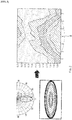
- The lighting device using the LED as a light source disposes a light distribution lens at a position corresponding to a light source unit, and uses by diffusing or collecting the light of the LED light source as necessary. As described above, if the light source is composed of a plurality of LED elements, a plurality of light distribution lenses may be arranged at positions corresponding to the respective LED elements. At this time, the plurality of light distribution lenses may be equally configured to have any one shape of oval or circular. For example, if the light distribution lens is applied to the oval lenses as illustrated in
FIG. 1 , the light distribution area projected by the oval lens is oval shape and its projection distance is short. Alternatively, if the light distribution lens is applied to the circular lenses as illustrated inFIG. 2 , the light distribution area projected by the circular lens is formed in a circular shape, and its projection distance is formed longer than that of the oval light distribution lens. However, there is a problem in that the circular light distribution lens has a large brightness difference between the center and the periphery of the light distribution area. - As described above, if only any one of the oval lens and the circular lens is used as the light distribution lens in the LED lighting device, the light distribution areas of adjacent lighting devices may overlap each other to increase the brightness, but dark portions (I, II) may be formed or distribution of lighting intensity may also be uneven. The formation of such a dark portion or non-uniformity of the lighting intensity may cause the driver to be optical illusion and fatigue, which may act as a serious factor that may cause a traffic accident.
- Further, a road lighting device such as a general street lamp is installed at a height of about 12m or more, there is a hassle to necessarily use a separate maintenance vehicle at the time of maintenance work of the lighting device.
- An object of the present disclosure is to provide a lens cover and an LED lighting device including the same, which may minimize occurrence of a dark portion even while extending the light distribution area of an LED light source.
- Further, another object of the present disclosure is to provide a lens cover and an LED lighting device including the same, which may sufficiently comply with the recommendations of the Road Traffic Act, such as an average brightness, an uniformity ratio of illumination, and an unified glare rating even if the installation height of the lighting device is implemented to a low height of less than 3m.
- For achieving the objects, a lens cover according to an embodiment of the present disclosure is the lens cover having a plurality of light distribution lenses arranged at positions corresponding to a plurality of LED light sources, and the plurality of light distribution lenses include a first light distribution lens and a second light distribution lens having different shapes from each other, and the first light distribution lens and the second light distribution lens are mixedly arranged at positions corresponding to the plurality of LED light sources.
- For achieving the objects, an LED lighting device according to an embodiment of the present disclosure includes a post, a head connected to one end of the post, and a lens cover coupled to the head, and the lens cover has a plurality of light distribution lenses arranged at positions corresponding to a plurality of LED light sources, the plurality of light distribution lenses include a first light distribution lens and a second light distribution lens having different shapes from each other, and the first light distribution lens and the second light distribution lens are mixedly arranged at positions corresponding to the plurality of LED light sources.
- According to an embodiment of the present disclosure, it is possible to provide the lighting device, which satisfies the recommendations of the Road Traffic Act, such as an average brightness, a uniformity ratio of illumination, and a unified glare rating even if the lighting device of a relatively low height is installed on the roadside.
-
-
FIG. 1 is a diagram schematically illustrating a light distribution diagram in a state where an oval lens is applied to a general LED lighting device. -
FIG. 2 is a diagram schematically illustrating a light distribution diagram in a state where a circular lens is applied to a general LED lighting device. -
FIG. 3 is a diagram schematically illustrating an LED lighting device according to an embodiment of the present disclosure. -
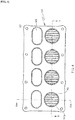
FIG. 4 is a plane diagram illustrating a cover for an LED lighting device according to an embodiment of the present disclosure. -
FIG. 5 is a cross-sectional diagram taken along the line "A-A" ofFIG. 4 . -
FIG. 6 is a cross-sectional diagram taken along the line "B-B" ofFIG. 3 . -
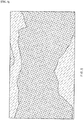
FIG. 7 is a diagram schematically illustrating a light distribution area projected on the lane from an LED lighting device according to an embodiment of the present disclosure. -
FIG. 8 is a diagram illustrating a light distribution diagram of a case of applying an LED lighting device according to an embodiment of the present disclosure. -
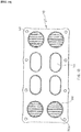
FIG. 9 is a front diagram illustrating a cover for an LED module according to another embodiment of the present disclosure. -
FIG. 10 is a front diagram illustrating a cover for an LED module according to still another embodiment of the present disclosure. - Hereinafter, the present disclosure will be described with reference to the accompanying drawings. However, the present disclosure may be implemented in various forms, and accordingly, is not limited to the embodiment described herein. Further, a portion irrelevant to the description has been omitted in the drawings for clearly describing the present disclosure, and like portions has been denoted by like reference numerals throughout the specification.
- Referring to
FIG. 3 , anLED street lamp 100 according to an embodiment of the present disclosure includes apost 110, ahead 120, and acover 140. - The
post 110 is fixedly installed on the installation surface (ground) of the roadside along the longitudinal direction of the road, and has a predetermined height. In an embodiment, thepost 110 may be formed at a low height of 3m or less. For example, if an LED lighting device according to an embodiment is installed adjacent to a bridge, the length of thepost 110 may be formed to be 3m or less, thereby minimizing interference with the bridge work of the maintenance vehicle. Further, it is possible to reduce the length of the post compared to the conventional, thereby reducing the manufacturing cost of each lighting device. - The
head 120 is connected to the upper portion of thepost 110 to have a predetermined inclination in one side direction. Thehead 120 may be provided with a heat dissipation member (not illustrated) so that at least one LED (seeFIG. 5 ) is operated within a range of a proper temperature. - The
cover 140 is coupled to one side of thehead 120, and thecover 140 may secure a light distribution area of a setting range. A printed circuit board on which a plurality of LEDs are mounted is accommodated inside thecover 140, that is, between thecover 140 and thehead 120. Assuming a two-lane road, thecover 140 may be formed at an angle (α) of 10° or more and 15° or less with respect to the axis extending from thepost 110. - Referring to
FIGS. 4 to 6 , theLED lighting device 100 according to an embodiment includes anLED module 130 and thecover 140. - The
LED module 130 is coupled so that light is distributed to one side of thehead 120, for example, the roadside. TheLED module 130 is manufactured in the form of a module in which a plurality ofLEDs 132 are mounted on a printedcircuit board 131. The number of theLEDs 132 used in theLED module 130 may be determined according to the length, the intensity of illumination, or the like of theset post 110. - The
cover 140 has a lens matrix composed of a plurality of lenses. In other words, thecover 140 includes a firstlight distribution lens 141 and a secondlight distribution lens 142 having different shapes from each other, and the firstlight distribution lens 141 and the secondlight distribution lens 142 are mixedly arranged with each other. - The first
light distribution lens 141 irradiates light at a relatively short distance from the lighting device with respect to the lighting device, and the secondlight distribution lens 142 irradiates light at a farther distance than the firstlight distribution lens 141. The firstlight distribution lens 141 is formed to have an oval hemispherical shape (hemispherical shape with different diameters of X and Y axes from each other when viewed in plane), and the secondlight distribution lens 142 is formed to have a hemispherical shape. - At this time, at least one
uneven portion 142a is provided on the surface of the secondlight distribution lens 142. Theuneven portion 142a is formed in the same direction as the axial direction of thepost 110. Theuneven portion 142a increases the surface area of the secondlight distribution lens 142 and induces scattered reflection of light generated from theLED 132, thereby increasing the light distribution area of the light projected from the secondlight distribution lens 142. Accordingly, the light distribution range of the light may be more extended along the longitudinal direction of the road. - Referring to
FIG. 4 , thecover 140 of an embodiment has a lens matrix arranged in two rows, a plurality of firstlight distribution lenses 141 are arranged in a first row, and a plurality of secondlight distribution lenses 142 are arranged in a second row. However, the lens matrix is not necessarily limited thereto. For example, as inFIG. 9 , the firstlight distribution lenses 141 may be arranged at the outermost of both sides of the first row and the second row of thecover 140 and the secondlight distribution lenses 142 may be arranged between the first light distribution lenses, or as inFIG. 10 , the secondlight distribution lenses 142 may be arranged at the outermost of both sides of the first row and the second row of thecover 140 and the firstlight distribution lenses 141 may also be arranged between the second light distribution lenses. Further, in an embodiment, the lens is arranged to have a matrix of 4∗2, but the matrix of the lens may be increased or decreased as necessary. - Meanwhile, a plurality of
fastening holes 143 are formed at the periphery of thecover 140 for fastening with thehead 120, and thecover 140 may be coupled to thehead 120 by using a fixing member such as a screw penetrating thefastening hole 143. -
FIGS. 7 and8 illustrate a light distribution diagram after light has been projected on the lane in a state where an LED lighting device according to an embodiment of the present disclosure has been installed on the roadside. At this time, the height of the lighting device was 2.1m, the installation distance between the lighting devices was 8m, the width of the road was 7.2m (based on two lanes), the inclination angle of the cover was 10 degrees, the ambient temperature was 10°C, and the illuminance of the LED was 60001m. - Accordingly, the light distribution area projected from the lighting device is formed so that a plurality of substantially oval short-distance light distribution areas are overlapped with each other on the lane of a position close to the lighting device by the first
light distribution lenses 141, and a plurality of substantially circular long-distance light distribution areas are overlapped with each other on the lane of a position farther than the above by the secondlight distribution lenses 142. Further, the short-distance light distribution area by the firstlight distribution lenses 141 and the long-distance light distribution area by the secondlight distribution lenses 142 are also overlapped with each other. - Accordingly, it is possible to implement the uniform brightness distribution in both short and long distances with respect to the lighting device, and to minimize occurrence of the dark portion on the lane.
- Meanwhile, Table 1 below represents the results if the LED lighting device was installed according to the installation environment as described above.
Table 1 Items Results Average brightness 3.1 Overall uniformity ratio of illumination 0.45 Uniformity ratio of illumination of lane axis 0.7 Unified glare rating 11% - According to the Road Traffic Act, it is recommended that uniformity ratio of illumination of an artificial lighting is 1/3 and the unified glare rating is within 15%. Here, the brightness represents the amount of light reflected from the target surface, and the uniformity ratio of illumination, as the degree of uniformity of illumination of the illuminance intensity distribution, represents a ratio of a high illuminance portion and a low illuminance portion. Accordingly, it may be seen that even if the lighting device of a relatively low height of 2.1m is applied as in an embodiment, the average brightness, the uniformity ratio of illumination, and the unified glare rating all satisfy the recommendations.
- The foregoing description of the present disclosure is intended for illustration, and it will be understood by those skilled in the art to which the present disclosure pertains that the present disclosure may be easily modified in other specific forms without changing the technical spirit or essential feature of the present disclosure.
Claims (8)
- A lens cover having a plurality of light distribution lenses arranged at positions corresponding to a plurality of LED light sources,
wherein the plurality of light distribution lenses comprise a first light distribution lens and a second light distribution lens having different shapes from each other, and
wherein the first light distribution lens and the second light distribution lens are mixedly arranged at positions corresponding to the plurality of LED light sources. - The lens cover of claim 1,
wherein the first light distribution lens is an oval hemispherical shape, and the second light distribution lens is a hemispherical shape. - The lens cover of claim 2,
wherein the lens cover is coupled to a head of a lighting device,
wherein one or more uneven portions are formed on the surface of the second light distribution lens, and
wherein the one or more uneven portions are formed in the same direction as the axial direction of a post to which the head is connected. - The lens cover of claim 1,
wherein the lens cover is arranged at an angle of 10° or more and 15° or less with respect to the axis extending from the post of the lighting device. - The lens cover of claim 1,
wherein a plurality of first light distribution lenses are arranged on the outermost of both sides of the lens cover, and a plurality of second light distribution lenses are arranged between the plurality of first light distribution lenses. - The lens cover of claim 1,
wherein a plurality of second light distribution lenses are arranged on the outermost of both sides of the lens cover, and a plurality of first light distribution lenses are arranged between the plurality of second light distribution lenses. - An LED lighting device, comprising:a post;a head connected to one end of the post; anda lens cover coupled to the head,wherein the lens cover has a plurality of light distribution lenses arranged at positions corresponding to a plurality of LED light sources,wherein the plurality of light distribution lenses comprises a first light distribution lens and a second light distribution lens having different shapes from each other, andwherein the first light distribution lens and the second light distribution lens are mixedly arranged at positions corresponding to the plurality of LED light sources.
- The LED lighting device of claim 7,
wherein the post has the length of 3m or less.
Applications Claiming Priority (2)
| Application Number | Priority Date | Filing Date | Title |
|---|---|---|---|
| KR1020170073969A KR102109136B1 (en) | 2017-06-13 | 2017-06-13 | Lens cover and led light apparatus having the same |
| PCT/KR2018/006481 WO2018230881A1 (en) | 2017-06-13 | 2018-06-07 | Lens cover and led lighting device including same |
Publications (4)
| Publication Number | Publication Date |
|---|---|
| EP3640532A1 true EP3640532A1 (en) | 2020-04-22 |
| EP3640532A4 EP3640532A4 (en) | 2021-03-03 |
| EP3640532C0 EP3640532C0 (en) | 2024-10-23 |
| EP3640532B1 EP3640532B1 (en) | 2024-10-23 |
Family
ID=64660969
Family Applications (1)
| Application Number | Title | Priority Date | Filing Date |
|---|---|---|---|
| EP18818710.8A Active EP3640532B1 (en) | 2017-06-13 | 2018-06-07 | Lens cover and led lighting device including same |
Country Status (5)
| Country | Link |
|---|---|
| US (1) | US10830414B2 (en) |
| EP (1) | EP3640532B1 (en) |
| KR (1) | KR102109136B1 (en) |
| CN (1) | CN110720011B (en) |
| WO (1) | WO2018230881A1 (en) |
Families Citing this family (1)
| Publication number | Priority date | Publication date | Assignee | Title |
|---|---|---|---|---|
| KR102778815B1 (en) * | 2019-07-12 | 2025-03-11 | 주식회사 아모센스 | Led lighting apparatus |
Family Cites Families (26)
| Publication number | Priority date | Publication date | Assignee | Title |
|---|---|---|---|---|
| TW457732B (en) * | 1999-08-27 | 2001-10-01 | Lumileds Lighting Bv | Luminaire, optical element and method of illuminating an object |
| US6773139B2 (en) * | 2001-09-17 | 2004-08-10 | Gelcore Llp | Variable optics spot module |
| JP2004199891A (en) | 2002-12-16 | 2004-07-15 | Matsushita Electric Works Ltd | Luminaire |
| JP2008108674A (en) * | 2006-10-27 | 2008-05-08 | Stanley Electric Co Ltd | LED lighting fixtures |
| CN101487573A (en) * | 2008-01-17 | 2009-07-22 | 宁波燎原灯具股份有限公司 | LED road lamp light distribution system |
| KR100890270B1 (en) * | 2008-09-02 | 2009-03-24 | 유동길 | Lighting device for street light with diffusion lens |
| CN102022637A (en) * | 2009-09-09 | 2011-04-20 | 富士迈半导体精密工业(上海)有限公司 | Illuminating device |
| CN102135239B (en) * | 2010-01-21 | 2013-01-23 | 财团法人工业技术研究院 | Illumination device and its optical element module |
| KR101756825B1 (en) * | 2010-08-24 | 2017-07-11 | 삼성전자주식회사 | Optical lens, led module and lighting apparatus having the optical lens |
| US20120307504A1 (en) * | 2011-06-03 | 2012-12-06 | Min-Hwa Chou | Lampshade for an led lamp |
| US20120307495A1 (en) * | 2011-06-06 | 2012-12-06 | Leotek Electronics Corporation | Optical lens and optical lens plate |
| CN202392611U (en) * | 2011-12-16 | 2012-08-22 | 深圳Tcl新技术有限公司 | High-power LED (light-emitting diode) and LED backlight module |
| US20140168975A1 (en) * | 2012-12-14 | 2014-06-19 | Avago Technologies General Ip (Singapore) Pte. Ltd | Lighting fixture with flexible lens sheet |
| CN203036555U (en) * | 2013-01-15 | 2013-07-03 | 重庆绿色科技开发有限公司 | Light emitting diode (LED) light distribution lens with good uniformity and high luminous efficiency |
| ITMI20131386A1 (en) * | 2013-08-12 | 2015-02-13 | Clay Paky Spa | STAGE PROJECTOR |
| CN203963816U (en) * | 2014-07-23 | 2014-11-26 | 周云霞 | A kind of LED diffuser |
| CN204268371U (en) * | 2014-12-06 | 2015-04-15 | 深圳市格天光电有限公司 | The high-boron-silicon glass lens of brilliant COB light source are covered for street lamp |
| KR20160091515A (en) | 2015-01-23 | 2016-08-03 | (주)예성 | Led streetlight |
| CN106152059A (en) * | 2015-03-27 | 2016-11-23 | 重庆雷嘉光电科技有限公司 | A kind of projection-type LED automobile long-and-short distant light optical lighting system |
| CN104949002A (en) * | 2015-04-13 | 2015-09-30 | 鲁东大学 | Large-range uniform light distributing method for LED high-pole lamp |
| AT517156B1 (en) * | 2015-05-06 | 2017-05-15 | Zkw Group Gmbh | Lighting device for a vehicle headlight |
| CN204879957U (en) * | 2015-07-15 | 2015-12-16 | 中微光电子(潍坊)有限公司 | Grading lens subassembly and LED tunnel lamp of LED light |
| KR101708377B1 (en) * | 2016-01-29 | 2017-02-20 | 삼성유리공업 주식회사 | Led street lamp for roadway lighting |
| KR101723669B1 (en) * | 2016-08-31 | 2017-04-05 | 최정우 | Lighting Apparatus for Pedestrian Crossing Zone |
| CN208170198U (en) * | 2018-02-01 | 2018-11-30 | 深圳市深大南方实业发展有限公司 | A kind of night light for building of good illumination effect |
| CN110230794B (en) * | 2019-05-31 | 2021-10-01 | 上海宝冶集团有限公司 | Street lamp installation method in electronic factory building |
-
2017
- 2017-06-13 KR KR1020170073969A patent/KR102109136B1/en active Active
-
2018
- 2018-06-07 EP EP18818710.8A patent/EP3640532B1/en active Active
- 2018-06-07 WO PCT/KR2018/006481 patent/WO2018230881A1/en not_active Ceased
- 2018-06-07 CN CN201880038188.5A patent/CN110720011B/en active Active
- 2018-06-07 US US16/622,260 patent/US10830414B2/en active Active
Also Published As
| Publication number | Publication date |
|---|---|
| KR20180135651A (en) | 2018-12-21 |
| KR102109136B1 (en) | 2020-05-11 |
| US20200103092A1 (en) | 2020-04-02 |
| CN110720011A (en) | 2020-01-21 |
| EP3640532C0 (en) | 2024-10-23 |
| WO2018230881A1 (en) | 2018-12-20 |
| EP3640532B1 (en) | 2024-10-23 |
| EP3640532A4 (en) | 2021-03-03 |
| US10830414B2 (en) | 2020-11-10 |
| CN110720011B (en) | 2021-02-05 |
Similar Documents
| Publication | Publication Date | Title |
|---|---|---|
| US8540397B2 (en) | Lighting apparatus using light emitting diode | |
| US20130051030A1 (en) | Asymmetric type lens and street lamp including the same | |
| US8240879B2 (en) | Illumination module | |
| CN101235946A (en) | Uniform Lighting Module | |
| JP6054403B2 (en) | Lighting method for LED lighting device | |
| KR101506492B1 (en) | housing of tunnel lamp | |
| US10830414B2 (en) | Lens cover and LED lighting device having lenses arranged at positions corresponding to LED light sources | |
| US8287154B2 (en) | LED lighting apparatus | |
| KR101004786B1 (en) | Lighting device using light emitting diode | |
| KR101723164B1 (en) | Led luminaire | |
| HUP0900709A2 (en) | Led-luminaire | |
| KR101217063B1 (en) | Led lighting apparatus | |
| KR101221967B1 (en) | Led illumination device | |
| CN202253126U (en) | Glare-free light-emitting diode (LED) streetlamp | |
| TWM442474U (en) | Structure of LED lens | |
| KR20120009880A (en) | Reflector for LED Lamp | |
| KR20110129193A (en) | Street lamp and his road lighting method | |
| CN202056757U (en) | Novel reflective housing of LED street lamp | |
| CN102853327B (en) | The LED street lamp of free from glare | |
| KR101308400B1 (en) | Led lamp module for streetlight for improving uniformity ratio of illuminance | |
| CN201897180U (en) | Light-distribution lens module for LED (light-emitting diode) street lamp | |
| KR20140001676A (en) | Led secondary lens | |
| KR101503498B1 (en) | Lighting device for street | |
| CN204554508U (en) | a floodlight | |
| KR20110040325A (en) | LED lighting with adjustable brightness and illuminance |
Legal Events
| Date | Code | Title | Description |
|---|---|---|---|
| STAA | Information on the status of an ep patent application or granted ep patent |
Free format text: STATUS: THE INTERNATIONAL PUBLICATION HAS BEEN MADE |
|
| PUAI | Public reference made under article 153(3) epc to a published international application that has entered the european phase |
Free format text: ORIGINAL CODE: 0009012 |
|
| STAA | Information on the status of an ep patent application or granted ep patent |
Free format text: STATUS: REQUEST FOR EXAMINATION WAS MADE |
|
| 17P | Request for examination filed |
Effective date: 20191204 |
|
| AK | Designated contracting states |
Kind code of ref document: A1 Designated state(s): AL AT BE BG CH CY CZ DE DK EE ES FI FR GB GR HR HU IE IS IT LI LT LU LV MC MK MT NL NO PL PT RO RS SE SI SK SM TR |
|
| AX | Request for extension of the european patent |
Extension state: BA ME |
|
| DAV | Request for validation of the european patent (deleted) | ||
| DAX | Request for extension of the european patent (deleted) | ||
| RIN1 | Information on inventor provided before grant (corrected) |
Inventor name: SHIN, GYU WEON |
|
| A4 | Supplementary search report drawn up and despatched |
Effective date: 20210201 |
|
| RIC1 | Information provided on ipc code assigned before grant |
Ipc: F21W 131/103 20060101ALI20210126BHEP Ipc: F21V 5/00 20180101ALI20210126BHEP Ipc: G02B 3/00 20060101ALI20210126BHEP Ipc: F21S 8/08 20060101ALI20210126BHEP Ipc: F21V 5/04 20060101AFI20210126BHEP |
|
| STAA | Information on the status of an ep patent application or granted ep patent |
Free format text: STATUS: EXAMINATION IS IN PROGRESS |
|
| 17Q | First examination report despatched |
Effective date: 20221006 |
|
| GRAP | Despatch of communication of intention to grant a patent |
Free format text: ORIGINAL CODE: EPIDOSNIGR1 |
|
| STAA | Information on the status of an ep patent application or granted ep patent |
Free format text: STATUS: GRANT OF PATENT IS INTENDED |
|
| INTG | Intention to grant announced |
Effective date: 20240723 |
|
| GRAS | Grant fee paid |
Free format text: ORIGINAL CODE: EPIDOSNIGR3 |
|
| GRAA | (expected) grant |
Free format text: ORIGINAL CODE: 0009210 |
|
| STAA | Information on the status of an ep patent application or granted ep patent |
Free format text: STATUS: THE PATENT HAS BEEN GRANTED |
|
| AK | Designated contracting states |
Kind code of ref document: B1 Designated state(s): AL AT BE BG CH CY CZ DE DK EE ES FI FR GB GR HR HU IE IS IT LI LT LU LV MC MK MT NL NO PL PT RO RS SE SI SK SM TR |
|
| REG | Reference to a national code |
Ref country code: GB Ref legal event code: FG4D |
|
| REG | Reference to a national code |
Ref country code: CH Ref legal event code: EP |
|
| REG | Reference to a national code |
Ref country code: DE Ref legal event code: R096 Ref document number: 602018075792 Country of ref document: DE |
|
| REG | Reference to a national code |
Ref country code: IE Ref legal event code: FG4D |
|
| U01 | Request for unitary effect filed |
Effective date: 20241025 |
|
| U07 | Unitary effect registered |
Designated state(s): AT BE BG DE DK EE FI FR IT LT LU LV MT NL PT RO SE SI Effective date: 20241107 |
|
| PG25 | Lapsed in a contracting state [announced via postgrant information from national office to epo] |
Ref country code: IS Free format text: LAPSE BECAUSE OF FAILURE TO SUBMIT A TRANSLATION OF THE DESCRIPTION OR TO PAY THE FEE WITHIN THE PRESCRIBED TIME-LIMIT Effective date: 20250223 Ref country code: HR Free format text: LAPSE BECAUSE OF FAILURE TO SUBMIT A TRANSLATION OF THE DESCRIPTION OR TO PAY THE FEE WITHIN THE PRESCRIBED TIME-LIMIT Effective date: 20241023 |
|
| PG25 | Lapsed in a contracting state [announced via postgrant information from national office to epo] |
Ref country code: ES Free format text: LAPSE BECAUSE OF FAILURE TO SUBMIT A TRANSLATION OF THE DESCRIPTION OR TO PAY THE FEE WITHIN THE PRESCRIBED TIME-LIMIT Effective date: 20241023 |
|
| PG25 | Lapsed in a contracting state [announced via postgrant information from national office to epo] |
Ref country code: NO Free format text: LAPSE BECAUSE OF FAILURE TO SUBMIT A TRANSLATION OF THE DESCRIPTION OR TO PAY THE FEE WITHIN THE PRESCRIBED TIME-LIMIT Effective date: 20250123 |
|
| PG25 | Lapsed in a contracting state [announced via postgrant information from national office to epo] |
Ref country code: GR Free format text: LAPSE BECAUSE OF FAILURE TO SUBMIT A TRANSLATION OF THE DESCRIPTION OR TO PAY THE FEE WITHIN THE PRESCRIBED TIME-LIMIT Effective date: 20250124 |
|
| PG25 | Lapsed in a contracting state [announced via postgrant information from national office to epo] |
Ref country code: PL Free format text: LAPSE BECAUSE OF FAILURE TO SUBMIT A TRANSLATION OF THE DESCRIPTION OR TO PAY THE FEE WITHIN THE PRESCRIBED TIME-LIMIT Effective date: 20241023 |
|
| PG25 | Lapsed in a contracting state [announced via postgrant information from national office to epo] |
Ref country code: RS Free format text: LAPSE BECAUSE OF FAILURE TO SUBMIT A TRANSLATION OF THE DESCRIPTION OR TO PAY THE FEE WITHIN THE PRESCRIBED TIME-LIMIT Effective date: 20250123 |
|
| PG25 | Lapsed in a contracting state [announced via postgrant information from national office to epo] |
Ref country code: SM Free format text: LAPSE BECAUSE OF FAILURE TO SUBMIT A TRANSLATION OF THE DESCRIPTION OR TO PAY THE FEE WITHIN THE PRESCRIBED TIME-LIMIT Effective date: 20241023 |
|
| PG25 | Lapsed in a contracting state [announced via postgrant information from national office to epo] |
Ref country code: SK Free format text: LAPSE BECAUSE OF FAILURE TO SUBMIT A TRANSLATION OF THE DESCRIPTION OR TO PAY THE FEE WITHIN THE PRESCRIBED TIME-LIMIT Effective date: 20241023 |
|
| PG25 | Lapsed in a contracting state [announced via postgrant information from national office to epo] |
Ref country code: CZ Free format text: LAPSE BECAUSE OF FAILURE TO SUBMIT A TRANSLATION OF THE DESCRIPTION OR TO PAY THE FEE WITHIN THE PRESCRIBED TIME-LIMIT Effective date: 20241023 |
|
| U20 | Renewal fee for the european patent with unitary effect paid |
Year of fee payment: 8 Effective date: 20250624 |
|
| PLBE | No opposition filed within time limit |
Free format text: ORIGINAL CODE: 0009261 |
|
| STAA | Information on the status of an ep patent application or granted ep patent |
Free format text: STATUS: NO OPPOSITION FILED WITHIN TIME LIMIT |
|
| 26N | No opposition filed |
Effective date: 20250724 |
|
| REG | Reference to a national code |
Ref country code: CH Ref legal event code: H13 Free format text: ST27 STATUS EVENT CODE: U-0-0-H10-H13 (AS PROVIDED BY THE NATIONAL OFFICE) Effective date: 20260127 |
|
| PG25 | Lapsed in a contracting state [announced via postgrant information from national office to epo] |
Ref country code: MC Free format text: LAPSE BECAUSE OF FAILURE TO SUBMIT A TRANSLATION OF THE DESCRIPTION OR TO PAY THE FEE WITHIN THE PRESCRIBED TIME-LIMIT Effective date: 20241023 |
|
| PG25 | Lapsed in a contracting state [announced via postgrant information from national office to epo] |
Ref country code: IE Free format text: LAPSE BECAUSE OF NON-PAYMENT OF DUE FEES Effective date: 20250607 |
|
| PG25 | Lapsed in a contracting state [announced via postgrant information from national office to epo] |
Ref country code: CH Free format text: LAPSE BECAUSE OF NON-PAYMENT OF DUE FEES Effective date: 20250630 |
|
| PGFP | Annual fee paid to national office [announced via postgrant information from national office to epo] |
Ref country code: GB Payment date: 20260526 Year of fee payment: 9 |
|
| U20 | Renewal fee for the european patent with unitary effect paid |
Year of fee payment: 9 Effective date: 20260624 |
|
| PG25 | Lapsed in a contracting state [announced via postgrant information from national office to epo] |
Ref country code: CY Free format text: LAPSE BECAUSE OF FAILURE TO SUBMIT A TRANSLATION OF THE DESCRIPTION OR TO PAY THE FEE WITHIN THE PRESCRIBED TIME-LIMIT Effective date: 20241023 |