EP3640464A1 - Saddle-type vehicle having independent throttle-type engine mounted thereon - Google Patents
Saddle-type vehicle having independent throttle-type engine mounted thereon Download PDFInfo
- Publication number
- EP3640464A1 EP3640464A1 EP18835837.8A EP18835837A EP3640464A1 EP 3640464 A1 EP3640464 A1 EP 3640464A1 EP 18835837 A EP18835837 A EP 18835837A EP 3640464 A1 EP3640464 A1 EP 3640464A1
- Authority
- EP
- European Patent Office
- Prior art keywords
- independent throttle
- magnet type
- type motor
- throttle engine
- crankshaft
- Prior art date
- Legal status (The legal status is an assumption and is not a legal conclusion. Google has not performed a legal analysis and makes no representation as to the accuracy of the status listed.)
- Granted
Links
- 238000002485 combustion reaction Methods 0.000 claims abstract description 102
- 230000005611 electricity Effects 0.000 claims abstract description 96
- 239000003054 catalyst Substances 0.000 claims abstract description 90
- 230000009471 action Effects 0.000 claims abstract description 59
- 239000000446 fuel Substances 0.000 claims abstract description 22
- 230000003584 silencer Effects 0.000 claims abstract description 11
- 230000005540 biological transmission Effects 0.000 claims description 24
- 239000007858 starting material Substances 0.000 claims description 20
- 238000011144 upstream manufacturing Methods 0.000 claims description 14
- 230000004913 activation Effects 0.000 abstract description 13
- 238000004804 winding Methods 0.000 description 39
- 239000007789 gas Substances 0.000 description 34
- 230000004907 flux Effects 0.000 description 25
- MWUXSHHQAYIFBG-UHFFFAOYSA-N Nitric oxide Chemical compound O=[N] MWUXSHHQAYIFBG-UHFFFAOYSA-N 0.000 description 24
- 230000033001 locomotion Effects 0.000 description 18
- 238000010586 diagram Methods 0.000 description 17
- 238000006243 chemical reaction Methods 0.000 description 16
- 230000007423 decrease Effects 0.000 description 16
- 230000006870 function Effects 0.000 description 13
- 230000007246 mechanism Effects 0.000 description 12
- 238000001514 detection method Methods 0.000 description 11
- 230000006837 decompression Effects 0.000 description 10
- 238000002347 injection Methods 0.000 description 10
- 239000007924 injection Substances 0.000 description 10
- 230000008859 change Effects 0.000 description 9
- 230000006835 compression Effects 0.000 description 9
- 238000007906 compression Methods 0.000 description 9
- 238000001816 cooling Methods 0.000 description 8
- 239000004215 Carbon black (E152) Substances 0.000 description 7
- UGFAIRIUMAVXCW-UHFFFAOYSA-N Carbon monoxide Chemical compound [O+]#[C-] UGFAIRIUMAVXCW-UHFFFAOYSA-N 0.000 description 7
- 229910002091 carbon monoxide Inorganic materials 0.000 description 7
- 229930195733 hydrocarbon Natural products 0.000 description 7
- 150000002430 hydrocarbons Chemical class 0.000 description 7
- 239000000758 substrate Substances 0.000 description 7
- 229910000510 noble metal Inorganic materials 0.000 description 5
- 238000006722 reduction reaction Methods 0.000 description 5
- 239000000919 ceramic Substances 0.000 description 4
- 230000000977 initiatory effect Effects 0.000 description 4
- 239000000696 magnetic material Substances 0.000 description 4
- 230000009467 reduction Effects 0.000 description 4
- 230000008878 coupling Effects 0.000 description 3
- 238000010168 coupling process Methods 0.000 description 3
- 238000005859 coupling reaction Methods 0.000 description 3
- 229910052751 metal Inorganic materials 0.000 description 3
- 239000002184 metal Substances 0.000 description 3
- 238000000034 method Methods 0.000 description 3
- 230000003647 oxidation Effects 0.000 description 3
- 238000007254 oxidation reaction Methods 0.000 description 3
- KDLHZDBZIXYQEI-UHFFFAOYSA-N Palladium Chemical compound [Pd] KDLHZDBZIXYQEI-UHFFFAOYSA-N 0.000 description 2
- 230000003197 catalytic effect Effects 0.000 description 2
- 239000004020 conductor Substances 0.000 description 2
- 238000006073 displacement reaction Methods 0.000 description 2
- 238000004880 explosion Methods 0.000 description 2
- 239000000463 material Substances 0.000 description 2
- BASFCYQUMIYNBI-UHFFFAOYSA-N platinum Chemical compound [Pt] BASFCYQUMIYNBI-UHFFFAOYSA-N 0.000 description 2
- 239000000126 substance Substances 0.000 description 2
- 239000002253 acid Substances 0.000 description 1
- 230000006399 behavior Effects 0.000 description 1
- 230000008901 benefit Effects 0.000 description 1
- 239000003990 capacitor Substances 0.000 description 1
- 239000003638 chemical reducing agent Substances 0.000 description 1
- 239000002826 coolant Substances 0.000 description 1
- 230000001419 dependent effect Effects 0.000 description 1
- 230000000694 effects Effects 0.000 description 1
- 230000005669 field effect Effects 0.000 description 1
- 238000010438 heat treatment Methods 0.000 description 1
- 230000006872 improvement Effects 0.000 description 1
- 238000009434 installation Methods 0.000 description 1
- WABPQHHGFIMREM-UHFFFAOYSA-N lead(0) Chemical compound [Pb] WABPQHHGFIMREM-UHFFFAOYSA-N 0.000 description 1
- 230000007659 motor function Effects 0.000 description 1
- 229910052763 palladium Inorganic materials 0.000 description 1
- 230000002093 peripheral effect Effects 0.000 description 1
- 230000035699 permeability Effects 0.000 description 1
- 229910052697 platinum Inorganic materials 0.000 description 1
- 238000000746 purification Methods 0.000 description 1
- 230000004043 responsiveness Effects 0.000 description 1
- 229910052703 rhodium Inorganic materials 0.000 description 1
- 239000010948 rhodium Substances 0.000 description 1
- MHOVAHRLVXNVSD-UHFFFAOYSA-N rhodium atom Chemical compound [Rh] MHOVAHRLVXNVSD-UHFFFAOYSA-N 0.000 description 1
- 230000002000 scavenging effect Effects 0.000 description 1
- 239000000243 solution Substances 0.000 description 1
- 230000007704 transition Effects 0.000 description 1
- 238000003466 welding Methods 0.000 description 1
Images


Classifications
-
- F—MECHANICAL ENGINEERING; LIGHTING; HEATING; WEAPONS; BLASTING
- F02—COMBUSTION ENGINES; HOT-GAS OR COMBUSTION-PRODUCT ENGINE PLANTS
- F02D—CONTROLLING COMBUSTION ENGINES
- F02D41/00—Electrical control of supply of combustible mixture or its constituents
- F02D41/02—Circuit arrangements for generating control signals
- F02D41/04—Introducing corrections for particular operating conditions
- F02D41/06—Introducing corrections for particular operating conditions for engine starting or warming up
- F02D41/062—Introducing corrections for particular operating conditions for engine starting or warming up for starting
- F02D41/064—Introducing corrections for particular operating conditions for engine starting or warming up for starting at cold start
-
- F—MECHANICAL ENGINEERING; LIGHTING; HEATING; WEAPONS; BLASTING
- F02—COMBUSTION ENGINES; HOT-GAS OR COMBUSTION-PRODUCT ENGINE PLANTS
- F02B—INTERNAL-COMBUSTION PISTON ENGINES; COMBUSTION ENGINES IN GENERAL
- F02B61/00—Adaptations of engines for driving vehicles or for driving propellers; Combinations of engines with gearing
- F02B61/02—Adaptations of engines for driving vehicles or for driving propellers; Combinations of engines with gearing for driving cycles
-
- F—MECHANICAL ENGINEERING; LIGHTING; HEATING; WEAPONS; BLASTING
- F02—COMBUSTION ENGINES; HOT-GAS OR COMBUSTION-PRODUCT ENGINE PLANTS
- F02D—CONTROLLING COMBUSTION ENGINES
- F02D29/00—Controlling engines, such controlling being peculiar to the devices driven thereby, the devices being other than parts or accessories essential to engine operation, e.g. controlling of engines by signals external thereto
- F02D29/02—Controlling engines, such controlling being peculiar to the devices driven thereby, the devices being other than parts or accessories essential to engine operation, e.g. controlling of engines by signals external thereto peculiar to engines driving vehicles; peculiar to engines driving variable pitch propellers
-
- F—MECHANICAL ENGINEERING; LIGHTING; HEATING; WEAPONS; BLASTING
- F02—COMBUSTION ENGINES; HOT-GAS OR COMBUSTION-PRODUCT ENGINE PLANTS
- F02D—CONTROLLING COMBUSTION ENGINES
- F02D41/00—Electrical control of supply of combustible mixture or its constituents
- F02D41/02—Circuit arrangements for generating control signals
- F02D41/021—Introducing corrections for particular conditions exterior to the engine
- F02D41/0235—Introducing corrections for particular conditions exterior to the engine in relation with the state of the exhaust gas treating apparatus
- F02D41/024—Introducing corrections for particular conditions exterior to the engine in relation with the state of the exhaust gas treating apparatus to increase temperature of the exhaust gas treating apparatus
- F02D41/0255—Introducing corrections for particular conditions exterior to the engine in relation with the state of the exhaust gas treating apparatus to increase temperature of the exhaust gas treating apparatus to accelerate the warming-up of the exhaust gas treating apparatus at engine start
-
- F—MECHANICAL ENGINEERING; LIGHTING; HEATING; WEAPONS; BLASTING
- F02—COMBUSTION ENGINES; HOT-GAS OR COMBUSTION-PRODUCT ENGINE PLANTS
- F02N—STARTING OF COMBUSTION ENGINES; STARTING AIDS FOR SUCH ENGINES, NOT OTHERWISE PROVIDED FOR
- F02N11/00—Starting of engines by means of electric motors
- F02N11/04—Starting of engines by means of electric motors the motors being associated with current generators
-
- F—MECHANICAL ENGINEERING; LIGHTING; HEATING; WEAPONS; BLASTING
- F02—COMBUSTION ENGINES; HOT-GAS OR COMBUSTION-PRODUCT ENGINE PLANTS
- F02N—STARTING OF COMBUSTION ENGINES; STARTING AIDS FOR SUCH ENGINES, NOT OTHERWISE PROVIDED FOR
- F02N11/00—Starting of engines by means of electric motors
- F02N11/08—Circuits or control means specially adapted for starting of engines
- F02N11/0859—Circuits or control means specially adapted for starting of engines specially adapted to the type of the starter motor or integrated into it
-
- F—MECHANICAL ENGINEERING; LIGHTING; HEATING; WEAPONS; BLASTING
- F02—COMBUSTION ENGINES; HOT-GAS OR COMBUSTION-PRODUCT ENGINE PLANTS
- F02D—CONTROLLING COMBUSTION ENGINES
- F02D2200/00—Input parameters for engine control
- F02D2200/02—Input parameters for engine control the parameters being related to the engine
- F02D2200/10—Parameters related to the engine output, e.g. engine torque or engine speed
- F02D2200/101—Engine speed
-
- F—MECHANICAL ENGINEERING; LIGHTING; HEATING; WEAPONS; BLASTING
- F02—COMBUSTION ENGINES; HOT-GAS OR COMBUSTION-PRODUCT ENGINE PLANTS
- F02D—CONTROLLING COMBUSTION ENGINES
- F02D41/00—Electrical control of supply of combustible mixture or its constituents
- F02D41/0002—Controlling intake air
-
- F—MECHANICAL ENGINEERING; LIGHTING; HEATING; WEAPONS; BLASTING
- F02—COMBUSTION ENGINES; HOT-GAS OR COMBUSTION-PRODUCT ENGINE PLANTS
- F02N—STARTING OF COMBUSTION ENGINES; STARTING AIDS FOR SUCH ENGINES, NOT OTHERWISE PROVIDED FOR
- F02N2300/00—Control related aspects of engine starting
- F02N2300/10—Control related aspects of engine starting characterised by the control output, i.e. means or parameters used as a control output or target
- F02N2300/102—Control of the starter motor speed; Control of the engine speed during cranking
Definitions
- the present teaching relates to a straddled vehicle equipped with an independent throttle engine.
- a straddled vehicle equipped with an independent throttle engine is a straddled vehicle having an independent throttle engine mounted thereon.
- the independent throttle engine includes at least one cylinder, and a throttle valve corresponding to each cylinder.
- the present inventors studied the relationship between an early activation of a catalyst and a layout of the catalyst in a straddled vehicle equipped with an independent throttle engine.
- the catalyst is arranged near the engine, for the purpose of an early activation of the catalyst.
- the catalyst arranged near the engine has a high temperature when activated.
- the capability of cooling the cylinder may be influenced.
- the motorcycle according to PTL 1 aims to maintain the capability of cooling the cylinder by contriving the arrangement of the catalyst and cylinder, which however results in a restricted layout of the catalyst and cylinder.
- a layout of the catalyst and the cylinder which is likely to be influenced by the temperature of the catalyst is designed on the assumption that the catalyst is arranged near the engine.
- An attempt to design a layout of apparatuses or devices on the assumption that the catalyst is arranged near the engine as described above results in less versatility, which makes the motorcycle applicable to limited vehicles. It is also not easy to occasionally adjust the layout in accordance with a model, a vehicle design, and the like. In a straddled vehicle equipped with an independent throttle engine, a space for installation of devices or apparatuses is limited as compared to automobiles and the like. It is, therefore, desirable to obtain a degree of freedom for catalyst layout.
- the present inventors studied from another viewpoint. Specifically, the present inventors studied combustion in an independent throttle engine.
- a throttle valve is arranged closer to a combustion chamber, as compared to a single-throttle type multi-cylinder engine having a single throttle valve and a plurality of cylinders.
- the single throttle valve is disposed upstream of an intake manifold.
- the intake manifold normally includes: a surge tank located downstream of the throttle valve; and an intake pipe that connects the surge tank to a combustion chamber of each cylinder.
- the throttle valve is disposed in an intake pipe, and therefore the distance between the throttle valve and the combustion chamber is short.
- the present inventors conducted studies about having the independent throttle engine perform no combustion action while the crankshaft is rotating at an extremely low speed at a time of cold-starting the independent throttle engine.
- the present inventors consequently conceived the idea of, at a time of cold-starting the independent throttle engine, firstly causing a magnet type motor to rotate the crankshaft without any combustion action of the independent throttle engine until the rotation speed of the crankshaft exceeds an idling rotation speed, and then, after the rotation speed of the crankshaft exceeds the idling rotation speed, starting the combustion action of the independent throttle engine.
- a straddled vehicle equipped with an independent throttle engine may employ the following configurations.
- the magnet type motor uses electricity in the electricity storage device to cause a forward rotation of the crankshaft with the combustion action of the independent throttle engine stopped, until the rotation speed of the crankshaft exceeds the idling rotation speed of the independent throttle engine. Then, (B) in a state where the rotation speed of the crankshaft exceeds the idling rotation speed of the independent throttle engine, the independent throttle engine supplies air through the or each throttle valve as well as a fuel to the or each corresponding cylinder and starts the combustion action.
- the restriction on the catalyst layout can be reduced. It is, therefore, possible that, for example, a portion of the exhaust passage located between the catalyst and the independent throttle engine is made relatively long, with an attempt at an early activation of the catalyst. It is also possible that the catalyst is arranged near the independent throttle engine, with an attempt at a further early activation of the catalyst. Accordingly, the straddled vehicle equipped with the independent throttle engine of (1) can achieve both a degree of design freedom for the catalyst layout and an early activation of the catalyst.
- connection As used herein, the terms “attached”, “connected”, “coupled”, and/or equivalents thereof are used in a broad sense, and include both of direct and indirect attachment, connection, and coupling.
- connection can mean not only physical or mechanical connection or coupling but also direct or indirect electrical connection or coupling.
- This Description describes a straddled vehicle equipped with a novel independent throttle engine.
- An independent throttle engine includes at least one cylinder, and a throttle valve independent for each cylinder.
- a single cylinder engine is an example of the independent throttle engine.
- the independent throttle engine may be a multi-cylinder engine.
- the number of cylinders included in the independent throttle multi-cylinder engine is not particularly limited, and for example, may be two, three, or four.
- the independent throttle engine is a four-stroke engine having a high-load region and a low-load region during four strokes, for example.
- the four-stroke engine having a high-load region and a low-load region during four strokes is, for example, a single cylinder engine, a two-cylinder engine, a three-cylinder engine of unequal interval explosion type, or a four cylinder engine of unequal interval explosion type.
- the four-stroke engine having a high-load region and a low-load region during four strokes involves a risk that rotation of a crankshaft caused by a combustion action is less likely to stabilize in an extremely low-speed region.
- the engine may be, for example, a four-stroke engine not having a high-load region and a low-load region during four strokes.
- a cooling system is not particularly limited. For example, natural air-cooling, forced air-cooling, or water-cooling may be adoptable.
- the throttle valve may be operated by receiving an operation on an accelerator operator through a physical cable or the like, or may be operated by throttle-by-wire.
- the straddled vehicle equipped with the independent throttle engine is a straddled vehicle having an independent throttle engine mounted thereon.
- the straddled vehicle means a motor vehicle having a saddle where a driver sits astraddle.
- Non-limiting examples of the straddled vehicle include motorcycles, motor tricycles, and ATVs (All-Terrain Vehicles).
- Non-limiting examples of the motorcycle include scooter, moped, off-road, and on-road type motorcycles.
- the straddled vehicle equipped with the independent throttle engine capable of leaning into turns takes a turn
- the straddled vehicle equipped with the independent throttle engine leans toward the inside of a curve in order to oppose a centrifugal force acting on the straddled vehicle equipped with the independent throttle engine at a time of the turn.
- the straddled vehicle equipped with the independent throttle engine that satisfies (ii) above is configured such that the rotation speed of the crankshaft (that is, operations of the independent throttle engine and/or the magnet type motor) and switching of whether power transmission is allowed or disconnected by the power transmission device are controlled in accordance with an operation on the accelerator operator.
- the straddled vehicle equipped with the independent throttle engine that satisfies (iii) above can be walked and towed.
- the straddled vehicle equipped with the independent throttle engine that satisfies at least one of (i) to (iii) above encompasses: a straddled vehicle equipped with an independent throttle engine that satisfies one of (i) to (iii) above; a straddled vehicle equipped with an independent throttle engine that satisfies (i) and (ii) above; a straddled vehicle equipped with an independent throttle engine that satisfies (ii) and (iii) above; a straddled vehicle equipped with an independent throttle engine that satisfies (i) and (iii) above; and a straddled vehicle equipped with an independent throttle engine that satisfies all of (i), (ii), and (iii) above.
- the magnet type motor includes a rotor and a stator. Either one of the rotor or the stator includes a permanent magnet. The other includes a coil.
- a brushed DC motor is an example of a magnet type motor with a permanent magnet included in a stator.
- a brushless motor is an example of a magnet type motor with a permanent magnet included in a rotor. The number of phases of the brushless motor is not particularly limited. It may have a single phase or three phases.
- the magnet type motor functions as a motor to rotate the crankshaft at a time of starting the combustion action of the engine.
- the magnet type motor may be configured to function as a generator to generate electricity while being driven by the engine.
- the straddled vehicle equipped with the independent throttle engine may include a generator in addition to the magnet type motor.
- the magnet type motor may be a magnet type motor generator that functions as a generator, too.
- the magnet type motor may be either of radial gap type or of axial gap type.
- the magnet type motor of radial gap type may be either of outer rotor type or of inner rotor type.
- the rotor may be connected to the crankshaft such that power transmission between the rotor and the crankshaft is allowed without interposition of a clutch.
- the rotor may be configured such that power transmission between the rotor and the crankshaft is not disconnected.
- the rotor may be directly coupled to the crankshaft, for example.
- the rotor may be connected to the crankshaft with a fixed speed ratio gear interposed therebetween, for example.
- the rotor may be connected to the crankshaft such that power transmission between the rotor and the crankshaft is constantly allowed.
- the magnet type motor may be of interior permanent magnet type (IPM type) having a permanent magnet embedded in a magnetic material, or may be of surface permanent magnet type (SPM type) having a permanent magnet exposed from a magnetic material.
- the permanent magnet may comprise two or more permanent magnets each having one magnetic pole pair, or may comprise a single permanent magnet magnetized to have two or more magnetic pole pairs.
- the ratio of the number of magnetic poles to the number of slots is preferably more than 2/3, further preferably equal to or more than 1/1, still further preferably more than 1/1, and particularly preferably 4/3.
- the magnetic poles are arranged at equal intervals with respect to the circumferential direction.
- the magnet type motor may be installed in such a manner that electricity is supplied thereto only in a period for which a start operation is received.
- the magnet type motor may be installed in such a manner that upon reception of a start operation, electricity is supplied thereto, and after completion of an engine start, the electricity supply is stopped.
- the electricity storage device is a device that stores electricity.
- the electricity storage device has a capacity of supplying electricity to the magnet type motor, the capacity at least enabling the magnet type motor itself to rotate the crankshaft up to the idling rotation speed by using electricity in the electricity storage device.
- the electricity storage device is not particularly limited, and may be a battery or a capacitor, for example.
- the driven member according to an aspect of the present teaching is a wheel, for example.
- the driven member may be a screw propeller, for example.
- the number of driven members is not particularly limited. In a straddled vehicle including a front wheel and a rear wheel, only the front wheel, only the rear wheel, or both the front wheel and the rear wheel may serve as the driven member.
- the accelerator operator is a member that receives a torque request caused by a driver operating the accelerator operator.
- the accelerator operator is not particularly limited, and may be an accelerator grip, an accelerator pedal, a component constituted of a lever, or a component constituted of a button.
- the accelerator operator may be connected to a throttle valve included in the engine via a mechanical wire, for example.
- the accelerator operator may be electrically connected to a motor and a control device for driving the throttle valve, for example.
- the control section has a function to control the engine and a function to control the magnet type motor.
- the function to control the magnet type motor is a function to switch on/off the electricity supply to the magnet type motor, for example.
- the function to control the magnet type motor is a control on the inverter circuit for example, and more specifically is an on/off control on each of the plurality of switching parts.
- a hardware configuration of the control section is not particularly limited.
- the control section may be constituted of a computer including a central processing unit and a storage device.
- the control section may be partially or entirely constituted of a wired logic which is an electronic circuit.
- a cold start means a start in a state where the independent throttle engine is not warmed up.
- the independent throttle engine has a temperature substantially equal to or lower than the outside air temperature, for example.
- Whether or not a start of the independent throttle engine is a cold start is determined based on, for example, a detection result obtained by a temperature sensor disposed in or near the independent throttle engine.
- whether or not a start of the independent throttle engine is a cold start may be determined based on, for example, the time elapsed since the combustion action of the independent throttle engine is stopped or since the straddled vehicle equipped with the independent throttle engine stops traveling.
- (A) and (B) above are implemented at least at a time of cold-starting.
- (A) and (B) above may be implemented at a time other than cold-starting.
- (A) and (B) above may be implemented in each starting, irrespective of whether or not the start is a cold start. It is not always necessary that (A) and (B) above be implemented in every cold-starting.
- the straddled vehicle equipped with the independent throttle engine may be configured to be capable of accepting setting on whether or not (A) and (B) above are implement at a time of starting.
- the straddled vehicle equipped with the independent throttle engine according to the present teaching may be configured such that, at a time of cold-starting, (A) and (B) above are implemented if a predetermined condition is satisfied while (A) and (B) above are not implemented if the predetermined condition is not satisfied.
- the straddled vehicle equipped with the independent throttle engine according to the present teaching may be configured such that, at a time of cold-starting, (A) and (B) above are implemented if the independent throttle engine has a temperature less than a predetermined temperature while (A) and (B) above are not implemented if the independent throttle engine has a temperature equal to or more than the predetermined temperature.
- the magnet type motor may stop providing a positive torque in the forward rotation direction of the crankshaft, by the time the rotation speed of the crankshaft exceeds the value of:
- the magnet type motor may stop providing a positive torque in the forward rotation direction of the crankshaft, after the rotation speed of the crankshaft exceeds the clutch-stall rotation speed.
- the idling over-rotation speed may be a rotation speed a predetermined rotation speed (e.g., 100 rpm, 200 rpm, or 300 rpm) higher than the idling rotation speed, or may be a predetermined rotation speed (e.g., 2000 rpm or 2500 rpm) higher than the idling rotation speed.
- the clutch-in rotation speed means a rotation speed of the crankshaft at a time when clutch-in occurs.
- the clutch-stall rotation speed means a rotation speed of the crankshaft at a time when clutch-stall occurs.
- the straddled vehicle 1 includes a silencer 25.
- the silencer 25 is disposed downstream of the exhaust passage 29.
- the catalyst 23 includes a substrate and a catalytic material attached to a surface of the substrate.
- the catalytic material includes a support and a noble metal.
- the support is disposed between the noble metal and the substrate.
- the support supports the noble metal thereon.
- the noble metal purifies the exhaust gas. Examples of the noble metal include platinum, palladium, and rhodium which remove HC, CO, and NOx, respectively.
- the catalyst 23 has a porous structure.
- the porous structure is a structure having many perforations formed in its cross-sections perpendicular to a direction in which the exhaust path 29 extends.
- An example of the porous structure is a honeycomb structure.
- the catalyst 23 may be either a metal-based catalyst or a ceramic-based catalyst.
- the metal-based catalyst is a catalyst having a metallic substrate.
- the ceramic-based catalyst is a catalyst having a ceramic substrate.
- the substrate of the metal-based catalyst is formed by, for example, winding an alternate stack of metallic corrugated plates and metallic flat plates.
- the substrate of the ceramic-based catalyst is, for example, a honeycomb structure body.
- the catalyst may not necessarily be a three-way catalyst.
- the catalyst may be a catalyst that removes any one or two of HC, CO, or NOx.
- the catalyst may not necessarily be a redox catalyst.
- the catalyst may be an oxidation catalyst or a reduction catalyst that removes harmful substances through either one of oxidation or reduction. Examples of the reduction catalyst include a catalyst that removes NOx through a reduction reaction.
- the straddled vehicle 1 includes an electricity storage device 4.
- the electricity storage device 4 supplies electricity to the magnet type motor M.
- the electricity storage device 4 is charged with electricity that is generated by the magnet type generator G.
- the straddled vehicle 1 includes a power transmission device PT.
- the power transmission device PT is configured to transmit power from the crankshaft 15 to the wheel 3b.
- the power transmission device PT includes a transmission TR (see FIG. 2 ) and a clutch CL.
- the transmission TR is a continuously variable transmission, for example.
- the transmission TR is capable of changing a gear ratio which is the ratio of a rotation speed input to a rotation speed output.
- the transmission TR is capable of changing the gear ratio corresponding to the rotation speed of the crankshaft 15 relative to the rotation speed of the wheel.
- the clutch CL is a drum type centrifugal clutch, for example.
- the combustion action of the independent throttle engine EG is stopped. Before the cold start, the wheel 3b is not driven at least by the independent throttle engine EG.
- the starter switch 6 is omitted and the main switch 5 serves as the starter switch 6. With such a configuration, upon an operation on the main switch 5 in the drive stop state, electricity supply to the control device 60 is started, and energization of the magnet type motor M is started. It may be also acceptable that the accelerator operator 8 serves as both the main switch 5 and the starter switch 6 at a time of start. With such a configuration, upon an operation on the accelerator operator 8 in the drive stop state, electricity supply to the control device 60 is started, and energization of the magnet type motor M is started.
- the independent throttle engine EG includes a crank case 11, the cylinder 12, a piston 13, a connecting rod 14, and the crankshaft 15.
- the piston 13 is disposed in the cylinder 12 and is capable of reciprocating therein.
- the crankshaft 15 is disposed in the crank case 11 and is rotatable therein.
- the crankshaft 15 is coupled to the piston 13 via the connecting rod 14.
- a cylinder head 16 is attached to the upper side of the cylinder 12.
- the cylinder 12, the cylinder head 16, and the piston 13 define the combustion chamber 28.
- the cylinder head 16 has an exhaust valve 18 and an intake valve 21.
- the exhaust valve 18 controls discharge of an exhaust gas from the cylinder 12.
- the intake valve 21 controls supply of a mixed gas to the combustion chamber in the cylinder 12.
- the crankshaft 15 included in the independent throttle engine EG has a first end portion 15a to which the magnet type generator G is attached. No clutch is disposed between the crankshaft 15 and the magnet type generator G.
- the crankshaft 15 included in the independent throttle engine EG has a second end portion 15b to which the power transmission device PT is provided.
- the first end portion 15a of the crankshaft 15 is a right end portion, and the second end portion 15b thereof is a left end portion.
- the independent throttle engine EG includes a decompression device D.
- the decompression device D is outlined in FIG. 2 .
- the decompression device D acts to decrease the pressure in the cylinder 12 in a compression stroke. In the compression stroke, the decompression device D opens the exhaust valve 18 so that a gas in the cylinder 12 is partially discharged.
- the decompression device D is configured to open the exhaust valve 18 in the compression stroke if the rotation speed of the crankshaft 15 is equal to or lower than a decompression upper limit speed that is set for the decompression device D.
- the camshaft Cs which rotates in conjunction with the crankshaft 15 is provided with a mechanism that causes the decompression device D to open the exhaust valve 18.
- the decompression device D for example, uses a centrifugal force involved in rotation of the camshaft Cs, for the action to open the exhaust valve 18. Since the decompression device D lowers the pressure of the mixed gas in the cylinder 12 in the compression stroke, a compression reaction force acting on the piston 13 is reduced. In a high-load region, a load on an action of the piston 13 is reduced.
- the independent throttle engine EG also includes the throttle valve 27 and a fuel injection device J (see FIG. 4 ).
- the throttle valve 27 is opened with an opening degree that is based on the amount of operation on the accelerator operator 8 (see FIG. 1 ).
- the throttle valve 27 adjusts the amount of flowing air in accordance with its opening degree, and thus adjusts the amount of air to be supplied into the cylinder 12.
- the fuel injection device J injects a fuel, and thus supplies the fuel to the combustion chamber 28 in the cylinder 12.
- a mixed gas composed of the air flowing through the throttle valve and the fuel injected from the fuel injection device J is supplied to the combustion chamber 28 in the cylinder 12.
- the independent throttle engine EG is provided with a spark plug 19.
- the spark plug 19 ignites the mixed gas in the cylinder 12, so that the mixed gas is combusted.
- the independent throttle engine EG includes a temperature sensor 51 (see FIG. 4 ).
- the control device 60 is able to acquire the temperature of the independent throttle engine EG based on a signal from the temperature sensor 51.
- the number of temperature sensors 51 is two or more, though only one temperature sensor 51 is illustrated in the Figure.
- the temperature sensor 51 may be, for example, a sensor for detecting an intake temperature, a sensor for detecting an exhaust temperature, or a sensor for detecting an oil temperature.
- the temperature sensor may be a sensor for detecting a coolant temperature. Whether or not a start is a cold start can be determined based on a temperature acquired from the temperature sensor 51.
- (A) and (B) mentioned above are performed in both cases of a cold start and other starts. There is no or reduced difference between a cold start and other starts, in terms of vehicle behaviors and time required before an engine start.
- This embodiment is one of preferred embodiments.
- the mixed gas containing the fuel supplied to the combustion chamber 28 is combusted so that the piston 13 moves.
- the combustion of the mixed gas makes the piston 13 reciprocate.
- the crankshaft 15 rotates.
- the power is outputted to the outside of the independent throttle engine EG through the crankshaft 15.
- the wheel 3b (see FIG. 1 ), which receives the power outputted from the independent throttle engine EG through the crankshaft 15, drives the straddled vehicle 1.
- the power of the crankshaft 15 is transmitted to the wheel 3b through the power transmission mechanism PT (see FIG. 1 ).
- the straddled vehicle 1 is driven by the wheel 3b receiving the power from the independent throttle engine EG through the crankshaft 15.
- FIG. 3 is an explanatory diagram schematically showing the relationship between a crank angle position of the independent throttle engine EG and a required torque.
- FIG. 3 shows a torque required for the crankshaft 15 to rotate with no combustion action of the independent throttle engine EG.
- the independent throttle engine EG is a four-stroke independent throttle engine.
- the independent throttle engine EG has, during one combustion cycle composed of four strokes, a high-load region TH in which a high load is put on rotation of the crankshaft 15 and a low-load region TL in which a load put on rotation of the crankshaft 15 is lower than the load in the high-load region TH.
- the high-load region means a region in one combustion cycle of the independent throttle engine EG where a load torque is higher than an average value Av of the load torque over the one combustion cycle.
- the low-load region TL is equal to or wider than the high-load region TH.
- the low-load region TL is wider than the high-load region TH.
- a rotation angle region corresponding to the low-load region TL is wider than a rotation angle region corresponding to the high-load region TH.
- the independent throttle engine EG repeats a combustion stroke (expansion stroke), an exhaust stroke, an intake stroke, and a compression stroke. The compression stroke overlaps the high-load region TH.
- One combustion cycle of the independent throttle engine EG includes one combustion stroke, one exhaust stroke, one intake stroke, and one compression stroke.
- the mixed gas is supplied to the combustion chamber.
- the piston 13 compresses the mixed gas in the combustion chamber.
- the mixed gas ignited by the spark plug 19 combusts and pushes the piston 13.
- an exhaust gas produced after the combustion is discharged out of the combustion chamber.
- FIG. 4 is a block diagram schematically showing a control system of the straddled vehicle shown in FIG. 1 .
- the straddled vehicle 1 includes the control device 60.
- the control device 60 is an ECU (Engine Control Unit).
- the control device 60 controls the independent throttle engine EG.
- the control device 60 is configured to control each part of the straddled vehicle 1, though not shown in FIG. 4 .
- the fuel injection device J, the spark plug 19, and the electricity storage device 4 are connected to the control device 60.
- a rotor position detection device 50 is connected to the control device 60.
- the control device 60 acquires the rotation speed of the crankshaft 15 based on a detection result obtained by the rotor position detection device 50.
- the straddled vehicle 1 is configured such that the rotor position detection device 50 acquires the rotation speed of the crankshaft 15, how to acquire the rotation speed of the crankshaft 15 is not limited to this example.
- a detector for detecting the rotation speed of the wheel 3b serving as a driven member may be provided in the straddled vehicle 1.
- the control device 60 (control section) is configured to acquire the rotation speed of the crankshaft 15.
- the control device 60 controls the spark plug 19 and the fuel injection device J, to control the combustion action of the independent throttle engine EG.
- the control device 60 controls the spark plug 19 and the fuel injection device J, to control the power of the independent throttle engine EG.
- the electricity storage device 4 is connected to the control device 60 via the main switch 5.
- the electricity storage device 4 is a lead-acid battery.
- Connected to the electricity storage device 4 are the magnet type motor M, a relay 26, the generator G, and a regulator 20.
- the main switch 5 is configured to be switched on/off by an ignition key.
- the electricity storage device 4 supplies electricity to the control device 60.
- the electricity storage device 4 supplies electricity to the fuel injection device J and the spark plug 19.
- Accessories (not shown) such as a headlight 7 (see FIG. 1 ) is connected to the control device 60.
- the main switch 5 When the main switch 5 is on, the accessories are supplied with electricity.
- the electricity storage device 4 Upon pushing of the starter switch 6, the electricity storage device 4 supplies electricity to the magnet type motor M, to drive the magnet type motor M.
- a fuse 4a is attached near the electricity storage device 4.
- the relay 26 includes a coil and a switch. When a current flows in the coil, the relay 26 functions as an electromagnet to attract the switch, so that the switch is turned on. When the relay 26 is turned on, electricity is supplied from the electricity storage device 4 to the magnet type motor M, to drive the magnet type motor M.
- the regulator 20 is disposed between the electricity storage device 4 and the magnet type generator G.
- the regulator 20 rectifies a voltage outputted from the magnet type generator G.
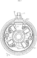
- FIG. 5 is a cross-sectional view of the magnet type motor M shown in FIG. 1 on an enlarge scale.
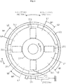
- FIG. 6 is a cross-sectional view of the magnet type motor M as taken along A-A in FIG. 5 .
- FIG. 7 is a cross-sectional view of the magnet type motor M as taken along B-B in FIG. 5 .
- the magnet type motor M includes a housing 202, a rotator 205, fixed brushes 222, 223, movable permanent magnets 203, and a magnet moving unit 225.
- the housing 202 of the magnet type motor M includes a tubular part 220a, a front cover 220b, and a rear cover 220c.
- the front cover 220b and the rear cover 220c are disposed so as to close openings at the opposite ends of the tubular part 220a.
- the tubular part 220a, the front cover 220b, and the rear cover 220c are fixed to one another by welding, for example.
- the tubular part 220a, the front cover 220b, and the rear cover 220c may be fixed to one another by a fastening member, for example.
- the housing 202 accommodates components of the magnet type motor M, including the rotator 205, the fixed brushes 222, 223, the movable permanent magnets 203, and the magnet moving unit 225.
- the housing 202 accommodates at least the rotator 205, the fixed brushes 222, 223, the movable permanent magnets 203, and the magnet moving unit 225.
- the housing 202 of the magnet type motor M has its position fixed relative to the independent throttle engine EG and the straddled vehicle 1.
- the rotator 205 is supported on the housing 202 such that the rotator 205 is rotatable relative to the housing 202.
- the rotator 205 includes a rotation shaft 206, a core 207, a commutator 208, and windings 209.
- the core 207 is fixed to the rotation shaft 206.
- the rotation shaft 206 is fitted in the core 207 so as to penetrate the core 207.
- the rotation shaft 206 is supported on the housing 202 with a bearing 214 interposed therebetween.
- the rotation shaft 206, the core 207, the commutator 208, and the windings 209 are rotated integrally.
- the direction in which the rotation shaft 206 of the rotator 205 extends will be referred to as an axis direction X, and the direction perpendicular to the axis direction X will be referred to as a radial direction R.
- the direction along rotation of the rotator 205 will be referred to as a circumferential direction C.
- the commutator 208 is arranged so as to surround the rotation shaft 206, and is electrically connected to the windings 209.
- the commutator 208 has contact pieces 208a the number of which corresponds to the number of teeth 207a.
- the coils constituted of the windings 209 are connected to the respective contact pieces 208a.
- the fixed brushes 222, 223 come into contact with the contact pieces 208a of the rotating commutator 208 one after another, so that a current flowing in the windings 209 is switched. That is, commutation of the windings 209 is caused.
- the movable permanent magnets 203 are disposed so as to face the core 207 with the air gap Y therebetween.
- the movable permanent magnets 203 are disposed so as to directly face the core 207.
- the magnet type motor M of this embodiment includes four movable permanent magnets 203.
- the movable permanent magnets 203 are disposed outside the core 207 of the rotator 205 with respect to the radial direction R.
- the movable permanent magnets 203 are disposed at positions surrounding the core 207.
- the movable permanent magnets 203 are arrayed such that N-pole and S-pole are alternately repeated in the circumferential direction C when viewed from the core 207.
- the movable permanent magnets 203 are supported on the housing 202.
- the movable permanent magnets 203 are supported on the housing 202 so as to be movable in the circumferential direction C independently of the rotator 205.
- An angle range through which the movable permanent magnets 203 move is within an adjustment angle range H.
- the adjustment angle range H is a predetermined angle range through which the movable permanent magnets 203 are allowed to move.
- the magnet type motor M of this embodiment includes a movable yoke part 231 disposed between the movable permanent magnets 203 and the housing 202.
- the plurality of movable permanent magnets 203 are fixed to the movable yoke part 231.
- the movable yoke part 231 is made of a magnetic material.
- the movable yoke part 231 is tubular.
- the housing 202 has a limiting part 202s that limits movement of the movable permanent magnets 203 out of the adjustment angle range H.
- the limiting part 202s is a projection that projects from the tubular part 220a of the housing 202 toward the center with respect to the radial direction R.
- the movable yoke part 231 has a cutout 203d.
- the limiting part 202s is disposed in the cutout 203d.
- the limiting part 202s limits the rotation angle of the movable yoke part 231, and thus limits movement of the movable permanent magnets 203.
- the limiting part 202s suppresses a situation where too much rotation of the movable permanent magnets 203 hinders rotation of the rotator 205.
- the magnet type motor M is configured such that an output torque of the magnet type motor M varies depending on the position of the movable permanent magnets 203 in the circumferential direction C.
- the position of the movable permanent magnets 203 in the circumferential direction where the magnet type motor M has the highest output torque is called a maximum torque position.
- the "retarded angle position" in the magnet type motor M is a position where the angle position of the movable permanent magnets 203 relative to the fixed brushes 222, 223 is displaced in the angle retard direction B from the maximum torque position.
- the advanced angle position of the movable permanent magnets 203 is a position displaced from the retarded angle position in the angle advance direction A.
- the advanced angle position is closer to the maximum torque position than the retarded angle position is.
- the advanced angle position may be substantially the same as the maximum torque position.
- the angle advance direction A is a direction opposite to the rotation direction D of the rotator 205 when the rotator 205 supplied with a current from the fixed brushes 222, 223 is rotating.
- the angle retard direction B is the same direction as the rotation direction D of the rotator. The retarded angle position and the advanced angle position will be detailed later.
- the magnet moving unit 225 is configured to move the movable permanent magnets 203.
- the magnet moving unit 225 moves the movable permanent magnets 203 in the angle retard direction B or in the angle advance direction A within the adjustment angle range, in a period for which a current is supplied to the rotator 205.
- FIG. 8 and FIG. 9 are schematic diagrams showing the positions of the fixed brushes 222, 223 and the movable permanent magnets 203 in the magnet type motor M shown in FIG. 7 .
- FIG. 8 and FIG. 9 illustrate the commutator 208 and the movable yoke part 231, too.
- FIG. 8 and FIG. 9 schematically illustrate the elastic member 225a.
- FIG. 8 the movable permanent magnets 203 in an advanced angle position L2 are illustrated with the solid lines.
- the position of each movable permanent magnet 203 is represented by the center position of this movable permanent magnet 203 with respect to the circumferential direction C.
- the movable permanent magnets 203 in a retarded angle position L1 are illustrated with the broken lines, for reference.
- the retarded angle position L1 is where the position of the movable permanent magnets 203 relative to the fixed brushes 222, 223 is displaced in the angle retard direction B from the advanced angle position L2.
- the angle advance direction A is the direction opposite to the rotation direction D of the rotator 205 when the rotator 205 supplied with a current from the fixed brushes 222, 223 is rotating.
- the angle retard direction B is the same direction as the rotation direction D of the rotator 205.
- the maximum torque position of the movable permanent magnets 203 is a position that causes the phase of a current flowing in a winding 209 to be substantially coincident with the phase of magnetic fluxes linked with the winding.
- the maximum torque position of the movable permanent magnets 203 is a position that causes a maximum induced voltage to occur between the fixed brushes 222, 223 when, for example, the magnet type motor M functioning as a generator is rotated by an external rotary force.
- an output torque T, a magnetic flux ⁇ , the number of poles P of the permanent magnets, the number of turns Z of the winding, and a current I satisfy the following relationship: T ⁇ ⁇ ⁇ PZI .
- ⁇ represents magnetic fluxes linked with a winding in which the current I flows.
- the current I is proportionate to a difference between a power source voltage of the starter motor and an induced voltage caused in the winding.
- the induced voltage caused in the winding is proportionate to a time derivative of the magnetic flux ⁇ .
- movement of the movable permanent magnets 203 to the retarded angle position L1 causes the magnetic fluxes ⁇ to be reduced as compared to the advanced angle position L2, the magnetic fluxes ⁇ being linked at a timing when the current I supplied from the fixed brushes 222, 223 flows.
- the movement of the movable permanent magnets 203 to the retarded angle position L1 causes the induced voltage to be lowered. Therefore, a current can be supplied to the winding under a high rotation speed. That is, an increased rotation speed can be outputted.
- the adjustment angle range in a case of moving the movable permanent magnets 203 from the maximum torque position to the retarded angle position L1 is less than 90° in electrical angle.
- the adjustment angle range is equal to or less than 30° in electrical angle.
- the electrical angle is an angle obtained under a condition that the angle of each pole pair of the movable permanent magnets 203 corresponds to 360°. Since the magnet type motor M of this embodiment includes two pairs of poles formed by the four movable permanent magnets 203 and the four fixed brushes 222, 223, it is preferable that the adjustment angle range H is equal to or less than 15° in mechanical angle.
- the elastic member 225a (see FIG. 5 ) of the magnet moving unit 225 exerts the elastic force to bias the movable permanent magnets 203 in the angle retard direction B.
- the elastic force of the elastic member 225a is weaker than a reaction force of the rotator 205 acting on the movable permanent magnets 203 at a time when the rotator 205 starts rotation, and is stronger than a reaction force of the rotator 205 acting on the movable permanent magnets 203 when the torque decreases along with an increase in the rotation speed of the rotator 205.
- the movable permanent magnets 203 are located in the retarded angle position L1 as shown in FIG. 9 , due to the biasing force of the elastic member 225a in the angle retard direction B.
- the output torque decreases based on an increase in the rotation speed of the rotator 205, and thus the reaction force of the rotator 205 acting on the movable permanent magnets 203 also decreases in accordance with the increase in the rotation speed of the rotator 205.
- the elastic force of the elastic member 225a is set so as to gradually weaken as the distance through which the elastic member 225a moves the movable permanent magnets 203 becomes longer.
- the relationship between the elastic force (loading) of the elastic member 225a and the distance through which the elastic member 225a moves the movable permanent magnets 203 may be linear (in direct proportion), substantially linear, or non-linear.
- movement of the movable permanent magnets 203 to the retarded angle position L1 shown in FIG. 9 is equivalent to, for example, movement of brushes to the advanced angle position provided the brushes are rotatable. Accordingly, movement of the movable permanent magnets 203 to the retarded angle position L1 makes the induced voltage less influential.
- a delay in a change of the current flowing in the winding 209 along with an increase in the rotation speed, which delay is caused by an inductance of the winding 9, is also made less influential by the movement of the movable permanent magnets 203 to the retarded angle position L1.
- the rotation speed of the rotator increases.
- FIG. 10 is a graph schematically showing rotation speed characteristics and output torque characteristics of the magnet type motor M shown in FIG. 6 .
- the solid line P indicates characteristics obtained when the movable permanent magnets 203 are located in the advanced angle position L2 shown in FIG. 8
- the solid line Q indicates characteristics obtained when the movable permanent magnets 203 are located in the retarded angle position L1 shown in FIG. 9 .
- a relatively high output torque is outputted under a low rotation speed, as indicated by the solid line P.
- a relatively high output torque Tp can be outputted at a time of starting rotation.
- the torque decreases relatively rapidly along with an increase in the rotation speed. As a result, a relatively low rotation speed can be outputted.
- the movable permanent magnets 203 are located in the advanced angle position L2 shown in FIG. 8 at a time point when the rotator 205 starts rotation upon a current supply to the rotator 205. This can provide an increased output torque, as indicated by the solid line P in FIG. 10 . Then, within the period for which the rotator 205 is rotating with the current supplied to the rotator 205, the movable permanent magnets 203 are moved in the angle retard direction B to the retarded angle position L1. This enables an improved rotation speed to be outputted, as indicated by the solid line Q in FIG. 10 . That is, in the magnet type motor M of this embodiment, the rotation speed characteristics and the output torque characteristics are changed from the characteristics indicated by the solid line P to the characteristics indicated by the solid line Q in FIG. 10 , within the period for which the rotator is rotating.
- both an operation state that provides an improved output torque under a low rotation speed and an operation state that increases the rotation speed when the torque is low can be achieved by movement of the movable permanent magnets 203, without movement of the fixed brushes 222, 223. Accordingly, the magnet type motor M can improve the output torque characteristics and the rotation speed characteristics for starting the independent throttle engine EG, with a simple configuration and with improvement in mountability to the straddled vehicle 1.
- the magnet type motor M causes the crankshaft 15 of the independent throttle engine EG which is in a stop state to rotate. At this time, the magnet type motor M is able to improve the output torque at a low rotation speed. After the combustion action of the independent throttle engine EG is started, the output torque decreases along with an increase in the rotation speed. At this time, the magnet type motor M causes the crankshaft 15 of the independent throttle engine EG to rotate at a high rotation speed, which can stabilize the action of the independent throttle engine EG.
- Examples of an adoptable brushed motor not having a movable permanent magnet include a fixed-type brushed motor having a position-fixed permanent magnet and three or more brushes disposed in different positions. The positions of the three or more brushes are fixed.
- a brush used to supply a current is switched from one brush to another brush, for changing characteristics.
- the characteristics are limited by the number of brushes. In addition, the characteristics are changed discontinuously by the switching.
- the magnet moving unit 225 of the magnet type motor M moves the movable permanent magnets 203 in the angle retard direction B to the retarded angle position L1 (see FIG. 9 ) based on an increase in the rotation speed of the rotator 205, within the period for which the rotator 205 is rotating with the current supplied to the rotator 205. Accordingly, the magnet type motor M can smoothly widen the rotation speed range of the rotator.
- the magnet moving unit 225 of the magnet type motor M uses the elastic force of the elastic member 225a as a force for biasing the movable permanent magnets 203 in the angle retard direction. This enables the magnet type motor M to improve output torque characteristics and rotation speed characteristics with a configuration simpler than, for example, using an actuator or a control device.
- the elastic force of the elastic member 225a of the magnet type motor M is weaker than the reaction force of the rotator acting on the movable permanent magnets 203 at a time when the rotator 205 starts rotation. In the first embodiment, therefore, at a time of initiating a cold start, the movable permanent magnets 203 first teeth 181 are moved in the angle advance direction A by the reaction force of the rotator. Thus, the cold start can be started in a state where the output torque of the magnet type motor M is increased.
- the elastic force of the elastic member 225a of the magnet type motor M is stronger than the reaction force of the rotator 205 acting on the movable permanent magnets 203 when the torque decreases along with an increase in the rotation speed of the rotator 205.
- the control device 60 operates the magnet type motor M and the independent throttle engine EG such that the independent throttle engine EG supplies air through the throttle valve 27 as well as a fuel to the cylinder 12 and starts the combustion action in a state where the rotation speed of the crankshaft 15 exceeds the idling rotation speed of the independent throttle engine EG.
- the rotation speed of the crankshaft 15 at a time of starting the combustion action is higher than the idling rotation speed.
- the combustion action is started before the clutch CT is let in, for example.
- the rotation speed of the crankshaft 15 at a time of starting the combustion action is lower than the rotation speed at a time of letting the clutch CT in, for example.
- the magnet type motor M stops driving the independent throttle engine EG. Consequently, the magnet type motor M stops rotation.
- the magnet type generator G which is driven by the independent throttle engine EG, keeps generating electricity even after the magnet type motor M stops rotation.
- FIG. 11 is a side view schematically showing a straddled vehicle 1 according to the second embodiment.
- the straddled vehicle 1 according to the second embodiment includes a magnet type motor generator MG instead of the magnet type motor M and the magnet type generator G of the first embodiment.
- the magnet type motor generator MG of this embodiment is disposed at a first end of the crankshaft 15.
- the magnet type motor generator MG is a three-phase brushless motor of permanent magnet type.
- FIG. 12 is a block diagram schematically showing a control system of the straddled vehicle 1 shown in FIG. 11 .
- the straddled vehicle 1 includes an inverter 61.
- the control device 60 controls respective parts, including the inverter 61, of the straddled vehicle 1.
- the magnet type motor generator MG and the electricity storage device 4 are connected to the inverter 61.
- the electricity storage device 4 supplies electricity to the magnet type motor generator MG.
- the electricity storage device 4 is charged with electricity that is generated by the magnet type motor generator MG.
- the electricity storage device 4 is connected to the inverter 61 via the main switch 5.
- the electricity storage device 4 is connected to accessories via the main switch 5.
- the switching parts 611 to 616 control a current flow between the electricity storage device 4 and the magnet type motor generator MG. Specifically, the switching parts 611 to 616 selectively allow or block the passing of a current between the electricity storage device 4 and the multi-phase stator windings W. More specifically, when the magnet type motor generator MG functions as a motor, energizing each of the multi-phase stator windings W is selectively allowed or stopped by on/off-operation on the switching parts 611 to 616. When the magnet type motor generator MG functions as a generator, the passing of a current between each of the stator windings W and the electricity storage device 4 is selectively allowed or blocked by on/off-operation on the switching parts 611 to 616.
- a voltage control and a rectification are performed on a three-phase AC outputted from the magnet type motor generator MG.
- the switching parts 611 to 616 control a current that the magnet type motor generator MG outputs to the electricity storage device 4.
- Each of the switching parts 611 to 616 has a switching element.
- the switching element is, for example, a transistor, and more specifically, an FET (Field Effect Transistor).
- the control device 60 acquires the amount of operation on the accelerator operator 8 and the rate of increase in the amount of operation based on, for example, a detection result obtained by a throttle position sensor (not shown).
- the control device 60 includes a starting and electricity generation control section 62, and a combustion control section 63.
- the starting and electricity generation control section 62 controls the on/off-operation on each of the switching parts 611 to 616, to control the operation of the magnet type motor generator MG.
- the starting and electricity generation control section 62 includes a drive control section 621 and an electricity generation control section 622.
- the starting and electricity generation control section 62 controls an adjustment mechanism 150 (see FIG. 14 ) which will be described later.
- the combustion control section 63 controls the spark plug 19 and the fuel injection device J, to control the combustion action of the independent throttle engine EG.
- the combustion control section 63 controls the spark plug 19 and the fuel injection device J, to control the power of the independent throttle engine EG.
- the combustion control section 63 controls the spark plug 19 and the fuel injection device J in accordance with the opening degree of the throttle valve 27 which is indicated by a signal outputted from the throttle position sensor.
- the control device 60 is composed of a computer including a central processing unit (not shown) and a storage device (not shown).
- the central processing unit executes arithmetic processing based on a control program.
- the storage device stores data relating to programs and arithmetic operations.
- the combustion control section 63 and the starting and electricity generation control section 62 including the drive control section 621 and the electricity generation control section 622 are implemented by a computer (not shown) and a control program executable by the computer.
- below-described operations performed respectively by the combustion control section 63 and by the starting and electricity generation control section 62 including the drive control section 621 and the electricity generation control section 622 can be considered as operations performed by the control device 60.
- the starting and electricity generation control section 62 and the combustion control section 63 may be, for example, either configured as separate devices placed at a distance from each other, or integrated as a single device.
- the starter switch 6 is connected to the control device 60.
- the starter switch 6 is actuated by the driver at a time of starting the independent throttle engine EG.
- the main switch 5 supplies electricity to the control device 60 in accordance with an operation on the main switch 5.
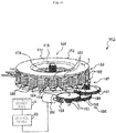
- FIG. 13 is an exploded perspective view schematically showing the magnet type motor generator MG included in the straddled vehicle 1 according to the second embodiment.
- FIG. 14 is a perspective view schematically showing the magnet type motor generator MG shown in FIG. 13 .
- FIG. 15 is a diagram schematically showing action of a stator in the magnet type motor generator MG shown in FIG. 13 .
- FIG. 16 is a diagram showing a principle of a rotation control on the magnet type motor generator MG shown in FIG. 13 .
- the magnet type motor generator MG includes a stator 142 composed of a first stator 183 and a second stator 187.
- An adjustment mechanism 150 which will be described later allows the second stator 187 to rotate about the crankshaft 15 relative to the first stator 183.
- FIG. 13 is an exploded perspective view of the magnet type motor generator MG having the first stator 183 and the second stator 187 arranged in this manner.
- FIG. 14 is a perspective view showing a state where the magnet type motor generator MG is assembled as well as the adjustment mechanism 150.
- FIG. 15 is a diagram showing the rotation angle and action of a reciprocating motion that the second stator 187 undergoes relative to the first stator 183 along the rotation direction of a rotor 144.
- FIG. 16 is a diagram showing a principle of a rotation control on the magnet type motor generator MG from high-torque/low-speed rotation to low-torque/high-speed rotation.
- the magnet type motor generator MG includes the rotor 144, and the rotor 144 is configured to rotate in a disk-like fashion about the crankshaft 15.
- the rotor 144 has a yoke 146 including a ring part 174, a taper part 175, a first cylindrical part 176, a second cylindrical part 178, a ring part 177, and permanent magnets 148.
- the rotor 144 has a plurality of detection object parts (not shown) to be detected by the rotor position detection device 50.
- the rotor 144 is connected to the crankshaft 15 such that the rotor 144 is rotated along with rotation of the crankshaft 15.
- No clutch is disposed between the rotor 144 and the crankshaft 15.
- a power transmission mechanism such as a belt, a chain, a gear, a speed reducer, or a speed increaser is not interposed between the rotor 144 and the crankshaft 15.
- the rotor 144 is rotated with a speed ratio of 1:1 relative to the crankshaft 15.
- Opposed to the rotor 144 are a plurality of first teeth 181 which are arranged with their first end surfaces 181a facing the rotor 144.
- Each of the first teeth 181 has peripheral side faces 181c which are different from its first and second end surfaces (181a, 181b) and on which a stator winding 182 is wound.
- Each of the first teeth 181 mentioned above is formed such that the end surface 181a facing the rotor 144 is wider than the opposite end surface 181b. Accordingly, the interval between adjacent ones of the first teeth 181 is narrow at a location close to the end surface 181a facing the rotor 144, and is wide at a location close to the opposite end surface 181b.
- the plurality of first teeth 181 with the stator windings 182 put thereon are molded integrally with the stator windings 182, to constitute the first stator 183 having a ring shape as a whole.
- a current for producing a torque which is applied to the stator windings 182 of the first teeth 181 of the first stator 183, is controlled based on a current control according to a basic driving method involving no field-weakening control.
- Second teeth 184 are arranged opposed to the end surfaces 181b of the first teeth 181 opposite to the end surfaces 181a facing the rotor 144.
- the number of second teeth 184 is equal to the number of first teeth 181.
- the second teeth 184 are arranged with their first end portions 184a facing the end surfaces 181b of the first teeth 181.
- the second teeth 184 have second end portions 184b that are press-fitted and fixed in a plurality of mounting holes 186 formed in an annular base 185.
- the second stator 187 is composed of the second teeth 184 and the base 185 having the mounting holes 186 in which the second teeth 184 are press-fitted and fixed.
- the second teeth 184 and the base 185 are molded, though not shown in the Figure.
- the second deceleration gear 192 has a large-diameter gear which is meshed with a small-diameter gear of the first deceleration gear 193.
- the first deceleration gear 193 has a large-diameter gear which is meshed with a worm gear 195 fixed to the distal end of a rotation shaft of the actuator 194.
- the second stator 187 is rotatable relative to the first stator 183 within a predetermined range in the rotation direction of the rotor 144.
- the second stator 187 undergoes stepless reciprocating motion with a predetermined rotation angle along the rotation direction of the rotor 144 (the direction indicated by the sign a in the Figure).
- FIG. 15(a) shows a positional relationship of the second teeth 184 relative to the first teeth 181, the positional relationship corresponding to high-torque/low-speed rotation of the magnet type motor generator MG shown in FIG. 14 .
- this positional relationship serves as a reference position.
- the above-described turning of the second stator 187 allows the second teeth 184 to turn (reciprocate) in a direction of the rotor 144 indicated by the arrow a, from the reference position shown in FIG. 15(a) which means a position where the second teeth 184 are opposed to the first teeth 181 to an intermediate position shown in FIG. 15(b) , and then to a maximum movement position shown in FIG.
- each of the second teeth 184 is located (for example, at the midpoint) between one first tooth 181 and another first tooth 181 adjacent to the one first tooth.
- the intermediate position shown in FIG. 15(b) represents an optional position that allows stepless and intermittent turning.
- FIG. 16 a principle of the rotation control on the magnet type motor generator MG from high-torque/low-speed rotation to low-torque/high-speed rotation according to this embodiment will be described.
- the stator windings 182 wound on the first teeth 181, a mold therefor, and a mold for the second teeth 184 and the base 185 are not shown, for easy understanding.
- FIG. 16(a) shows a state under high-torque/low-speed rotation, where the second teeth 184 are positioned opposed to the first teeth 181 as shown in FIG. 15(a) .
- FIG. 16(b) shows a state under low-torque/high-speed rotation, where each of the second teeth 184 is positioned between one first tooth 181 and another first tooth 181 adjacent to the one first tooth 181 as shown in FIG. 15(c) .
- FIG. 16(a) shows a state where the permanent magnets 148 of the rotor 144 are opposed to the first teeth 181 and the second teeth 184 are opposed to the first teeth 181. That is, FIG. 16(a) shows the same state as shown in FIG. 15(a) .
- FIG. 16(a) shows the same state as shown in FIG. 15(a) .
- FIG. 16(b) shows a state where each of the second teeth 184 is positioned between one first tooth 181 and another first tooth 181 adjacent to the one first tooth 181 without any change in the positional relationship between the permanent magnets 148 of the rotor 144 and the first teeth 181. That is, FIG. 16(b) shows the same state as shown in FIG. 15(c) .
- the yoke 146 of the rotor 144, the first teeth 181, the second teeth 184, and the base 185 have high magnetic permeabilities.
- An interval h between surfaces of the permanent magnets 148 and surfaces of the first teeth 181 facing each other and an interval k between surfaces of the first teeth 181 and surfaces of the second teeth 184 facing each other are extremely narrow. Therefore, an in-air magnetic resistance is low.
- the end surfaces 181a of the first teeth 181 facing the rotor 144 are wider than the other end surfaces 181b.
- an interval j formed between the end surfaces 181a of adjacent first teeth 181 facing the rotor 144 is extremely narrower than a distance between the other end surfaces.
- the interval j is wider than the interval h from the rotor 144.
- These intervals have a relationship of "h ⁇ k ⁇ j". Accordingly, magnetic fluxes produced between a permanent magnet 148i (assumed as N-pole) and a permanent magnet 148i-1 (assumed as S-pole) adjacent to the permanent magnet 148i hardly pass through the interval j, but form a strong flux flow 198a passing through the interval h, a first tooth 181i, the interval k, a second tooth 184i, the base 185, a second tooth 184i-1, the interval k, a first tooth 181i-1, the interval h, and the yoke 146.
- the permanent magnet 148i is not N-pole but is S-pole, the same phenomena occur so that strong flux flows are produced to pass through the corresponding permanent magnets 148, the corresponding first teeth 181, the corresponding second teeth 184, the base 185, and the yoke 146, except that the directions of the flux flows are opposite.
- the second teeth 184 are allowed to rotate (reciprocate) in a rotation direction of the rotor 144 indicated by the arrow a, from the reference position where the second teeth 184 are opposed to the first teeth 181 to a predetermined position (maximum movement position) where each of the second teeth 184 is located between one first tooth and another first tooth adjacent to the one first tooth.
- intervals have a relationship of "m ⁇ n". Since the interval n is wider than the interval m, the interval n is negligible for the interval m from the viewpoint of a magnetic resistance.
- the interval m is the shortest distance between each second tooth and the end surface 181b of the corresponding first tooth opposite to the end surface 181a facing the rotor 144.
- the end surfaces 181a of the first teeth 181 facing the rotor 144 are wider than the other end surfaces 181b.
- the interval j formed between the end surfaces 181a of adjacent first teeth 181 facing the rotor 144 is extremely narrow.
- the interval j and the interval m have a relationship of "j ⁇ m". That is, the distance (j) between an end surface 181a of one first tooth 181 facing the rotor 144 and an end surface 181a of another first tooth 181 facing the rotor 144 and adjacent to the one first tooth 181 is shorter than the shortest distance (interval m) between each second tooth 184 and the end surface 181b of the corresponding first tooth 181.
- magnetic fluxes produced between one permanent magnet 148i (N-pole) and another adjacent permanent magnet 148i+1 (S-pole) flow from the first tooth 181i neither to the second tooth 184i+1 nor to the base 185 due to flux resistances provided by the interval m and by the interval n, but form a weak flux flow 199b passing through only the first tooth 181i, the interval j, the first tooth 181i+1, and the yoke 146.
- the magnet type motor generator MG according to the second embodiment described above can change output performance at a time of driving the wheel 3b.
- the magnet type motor generator MG according to the second embodiment at a time of starting rotation of the crankshaft 15, for example, the second teeth 184 and the first teeth 181 are arranged as shown in FIG. 15(a) and FIG. 16(a) , so that a high torque can be outputted.
- the magnet type motor generator MG according to the second embodiment after the start of rotation of the crankshaft 15, for example, the second teeth 184 and the first teeth 181 are arranged as shown in FIG. 15(c) and FIG. 16(b) , so that high-speed rotation can be allowed.
- the electricity generation performance can be changed by changing the arrangement of the second teeth 184 and the first teeth 181.
- the control device 60 operates the magnet type motor generator MG and the independent throttle engine EG such that the independent throttle engine EG supplies air through the throttle valve 27 as well as a fuel to the cylinder 12 and starts the combustion action in a state where the rotation speed of the crankshaft 15 exceeds the idling rotation speed of the independent throttle engine EG.
- the magnet type motor generator MG stops driving the independent throttle engine EG upon the driver stopping the operation on the starter switch 6. Nevertheless, the magnet type motor generator MG is driven by the independent throttle engine EG to generate electricity, because the combustion of the independent throttle engine EG has been already started.
- the change in the rotation-speed/torque characteristics is not limited to the example illustrated above, and may be implemented based on a field-weakening control, for example.
- the change in the rotation-speed/torque characteristics is preferably implemented by changing the arrangement of the stator and/or the rotor as shown in the example illustrated above.
- Changing the arrangement of the stator and/or the rotor is not particularly limited, and may be implemented not only by the example illustrated above but also by, for example, adjusting the length of an air gap between the rotor and the stator.
- a magnet type motor having its rotation-speed/torque characteristics unchangeable may also be adopted.
Abstract
Description
- The present teaching relates to a straddled vehicle equipped with an independent throttle engine.
- A straddled vehicle equipped with an independent throttle engine is a straddled vehicle having an independent throttle engine mounted thereon. The independent throttle engine includes at least one cylinder, and a throttle valve corresponding to each cylinder.
- The straddled vehicle equipped with the independent throttle engine includes a catalyst for purifying an exhaust gas. When the independent throttle engine is started, the catalyst is heated by an exhaust gas, to change from an inactive state to an active state. The catalyst brought into the active state can exert a purification performance.
- Patent Literature 1 (PTL 1) discloses a motorcycle equipped with a single cylinder engine. The motorcycle equipped with the single cylinder engine is an example of the straddled vehicle equipped with the independent throttle engine. The motorcycle according to
PTL 1 has a catalyst arranged near the engine, and more specifically arranged near a cylinder or an exhaust valve. The motorcycle according to PTL 1 aims to both achieve an early activation of the catalyst and maintain a capability of cooling the cylinder, by means of a layout of the catalyst and cylinder. - PTL 1: Japanese Patent Application Laid-Open No.
2007-187004 -
PTL 1 proposes a layout of the catalyst and cylinder for both achieving an early activation of the catalyst and maintaining a capability of cooling the cylinder. The layout, however, may be difficult to apply to some models or designs of motorcycles, for example. Some models or designs of motorcycles, for example, involve a risk that a catalyst arranged near an engine may be strongly heated by the engine so that the catalyst has a high temperature. The catalyst having a high temperature may influence apparatuses and devices other than the cylinder. - An object of the present teaching is to provide a straddled vehicle equipped with an independent throttle engine capable of achieving both a degree of design freedom for catalyst layout and an early activation of a catalyst.
- The present inventors studied the relationship between an early activation of a catalyst and a layout of the catalyst in a straddled vehicle equipped with an independent throttle engine.
- In the motorcycle according to
PTL 1, the catalyst is arranged near the engine, for the purpose of an early activation of the catalyst. The catalyst arranged near the engine has a high temperature when activated. As a result, the capability of cooling the cylinder may be influenced. The motorcycle according to PTL 1 aims to maintain the capability of cooling the cylinder by contriving the arrangement of the catalyst and cylinder, which however results in a restricted layout of the catalyst and cylinder. - In the motorcycle according to
PTL 1, a layout of the catalyst and the cylinder which is likely to be influenced by the temperature of the catalyst is designed on the assumption that the catalyst is arranged near the engine. An attempt to design a layout of apparatuses or devices on the assumption that the catalyst is arranged near the engine as described above results in less versatility, which makes the motorcycle applicable to limited vehicles. It is also not easy to occasionally adjust the layout in accordance with a model, a vehicle design, and the like. In a straddled vehicle equipped with an independent throttle engine, a space for installation of devices or apparatuses is limited as compared to automobiles and the like. It is, therefore, desirable to obtain a degree of freedom for catalyst layout. - The present inventors studied from another viewpoint. Specifically, the present inventors studied combustion in an independent throttle engine.
- In the independent throttle engine, a throttle valve is arranged closer to a combustion chamber, as compared to a single-throttle type multi-cylinder engine having a single throttle valve and a plurality of cylinders. In the single-throttle type multi-cylinder engine, the single throttle valve is disposed upstream of an intake manifold. The intake manifold normally includes: a surge tank located downstream of the throttle valve; and an intake pipe that connects the surge tank to a combustion chamber of each cylinder. Thus, the distance between the throttle valve and the combustion chamber is long. In the independent throttle engine, on the other hand, the throttle valve is disposed in an intake pipe, and therefore the distance between the throttle valve and the combustion chamber is short. This provides a good responsiveness, because the amount of air to be supplied to the combustion chamber can easily make a quick change in accordance with an open/close action of the throttle valve. Here, since the throttle valve is arranged near the combustion chamber, an airflow in the combustion chamber is susceptible to influences from the open/close action of the throttle valve. Consequently, in a control of, after a magnet type motor starts rotating a crankshaft, starting a combustion action of the independent throttle engine and then increasing the rotation speed of the crankshaft up to an idling rotation speed, the stable implementation of (a) and (b) below may be sometimes difficult:
- (a) suppressing discharge of HC, CO, or NOx; and
- (b) raising the temperature of an exhaust gas discharged from the combustion chamber.
- As a result of further studies, the present inventors found out the following. In the independent throttle engine, while the crankshaft is rotating at an extremely low speed, an airflow into the combustion chamber is likely to be disturbed by the open/close action of the throttle valve, which may make the implementation of (a) and (b) above difficult. An increase in the rotation speed of the crankshaft makes the disturbance of the airflow less likely to occur.
- Based on the findings above, the present inventors conducted studies about having the independent throttle engine perform no combustion action while the crankshaft is rotating at an extremely low speed at a time of cold-starting the independent throttle engine. The present inventors consequently conceived the idea of, at a time of cold-starting the independent throttle engine, firstly causing a magnet type motor to rotate the crankshaft without any combustion action of the independent throttle engine until the rotation speed of the crankshaft exceeds an idling rotation speed, and then, after the rotation speed of the crankshaft exceeds the idling rotation speed, starting the combustion action of the independent throttle engine.
- Until the crankshaft exceeds the idling rotation speed, no combustion action of the independent throttle engine is performed, and the crankshaft is rotated by the magnet type motor. This makes it possible to implement (a) and (b) below:
- (a) effectively suppressing discharge of HC, CO, or NOx; and
- (b) making it easy to suppress discharge of HC, CO, or NOx while controlling the temperature of an exhaust gas, when raising the temperature of an exhaust gas discharged from the combustion chamber.
- It is possible to implement (a) and (b) above, conceivably because the crankshaft being rotated up to a rotation speed higher than the idling rotation speed with no combustion action of the independent throttle engine enables adequate scavenging to be done before an initial combustion action and also enables disturbance of an airflow in the combustion chamber to be suppressed due to an increase in the rotation speed of the crankshaft. Since the initial combustion action is performed in a state where the rotation speed of the crankshaft is higher than the idling rotation speed, an exhaust gas initially discharged from the combustion chamber can have an increased amount of heat. As the exhaust gas initially discharged from the combustion chamber at a time of cold-starting has a large amount of heat, the restriction on the catalyst layout can be reduced. For example, it is possible to provide a relatively long exhaust passage between the catalyst and the independent throttle engine, with an attempt at an early activation of the catalyst. It is also possible to arrange the catalyst near the independent throttle engine, with an attempt at an early activation of the catalyst. Accordingly, both a degree of design freedom for catalyst layout and an early activation of the catalyst can be achieved in the independent throttle engine.
- A straddled vehicle equipped with an independent throttle engine according to some aspects of the present teaching accomplished based on the findings described above may employ the following configurations.
- (1) In an aspect of the present teaching, a straddled vehicle equipped with an independent throttle engine includes:
- an independent throttle engine including at least one cylinder and a crankshaft, each of the at least one cylinder being provided with an independent throttle valve and a combustion chamber disposed inside the cylinder, the independent throttle engine being configured to output power through the crankshaft;
- an exhaust passage having a discharge port through which an exhaust gas discharged from the combustion chamber is discharged to the atmosphere, the exhaust passage being configured to let the exhaust gas pass therethrough from the combustion chamber to the discharge port;
- a silencer disposed downstream of the exhaust passage;
- a catalyst disposed in the exhaust passage and located upstream of an upstream end portion of the silencer;
- a magnet type motor including a rotor and a stator, the rotor being connected to the crankshaft such that power transmission between the rotor and the crankshaft is allowed, the stator being arranged opposed to the rotor, the rotor or the stator including a permanent magnet, the magnet type motor being configured to rotate the crankshaft at least when starting a combustion action of the independent throttle engine;
- an electricity storage device that supplies electricity to the magnet type motor;
- a driven member configured to be driven by power outputted from the independent throttle engine and/or the magnet type motor, to make the straddled vehicle equipped with the independent throttle engine move forward; and
- a control section configured to control the magnet type motor and the independent throttle engine such that, when cold-starting the independent throttle engine in a state where the combustion action of the independent throttle engine is stopped and the driven member is not driven, firstly, the magnet type motor uses electricity in the electricity storage device to cause a forward rotation of the crankshaft with the combustion action of the independent throttle engine stopped, until a rotation speed of the crankshaft exceeds an idling rotation speed of the independent throttle engine, and then in a state where the rotation speed of the crankshaft exceeds the idling rotation speed of the independent throttle engine, the independent throttle engine supplies air through the or each throttle valve as well as a fuel to the or each cylinder and starts the combustion action.
- In the straddled vehicle equipped with the independent throttle engine of (1), when cold-starting the independent throttle engine in a state where the combustion action of the independent throttle engine is stopped and the driven member is not driven, firstly, (A) the magnet type motor uses electricity in the electricity storage device to cause a forward rotation of the crankshaft with the combustion action of the independent throttle engine stopped, until the rotation speed of the crankshaft exceeds the idling rotation speed of the independent throttle engine. Then, (B) in a state where the rotation speed of the crankshaft exceeds the idling rotation speed of the independent throttle engine, the independent throttle engine supplies air through the or each throttle valve as well as a fuel to the or each corresponding cylinder and starts the combustion action. Implementation of (A) and (B) enables an initial combustion action to be performed in the combustion chamber that is adequately scavenged and has less disturbance of an airflow. Consequently, an exhaust gas initially discharged from the combustion chamber at a time of cold-starting has a larger amount of heat. The exhaust gas passes through the exhaust passage, and reaches the catalyst. The exhaust gas starts heating the catalyst, and the heated catalyst purifies the exhaust gas.
- As the exhaust gas initially discharged from the combustion chamber at a time of cold-starting has a large amount of heat, the restriction on the catalyst layout can be reduced. It is, therefore, possible that, for example, a portion of the exhaust passage located between the catalyst and the independent throttle engine is made relatively long, with an attempt at an early activation of the catalyst. It is also possible that the catalyst is arranged near the independent throttle engine, with an attempt at a further early activation of the catalyst. Accordingly, the straddled vehicle equipped with the independent throttle engine of (1) can achieve both a degree of design freedom for the catalyst layout and an early activation of the catalyst.
- The present teaching can provide a straddled vehicle equipped with an independent throttle engine capable of achieving both a degree of design freedom for catalyst layout and an early activation of a catalyst.
- The terminology used herein is for defining particular embodiments only and is not intended to be limiting the teaching.
- As used herein, the term "and/or" includes any and all combinations of one or more of the associated listed items.
- As used herein, the terms "including", "comprising", or "having", and variations thereof specify the presence of stated features, steps, operations, elements, components, and/or equivalents thereof, and can include one or more of steps, operations, elements, components, and/or their groups.
- As used herein, the terms "attached", "connected", "coupled", and/or equivalents thereof are used in a broad sense, and include both of direct and indirect attachment, connection, and coupling. In addition, the terms "connected" and "coupled" can mean not only physical or mechanical connection or coupling but also direct or indirect electrical connection or coupling.
- Unless otherwise defined, all terms (including technical and scientific terms) used herein have the same meaning as commonly understood by one of ordinary skill in the art to which the present teaching belongs.
- It will be further understood that terms, such as those defined in commonly used dictionaries, should be interpreted as having a meaning that is consistent with their meaning in the context of the present disclosure and relevant art and should not be interpreted in an idealized or overly formal sense unless expressly so defined herein.
- It will be understood that the description of the present teaching discloses the number of techniques and steps.
- Each of these has individual benefit and each can also be used in conjunction with one or more, or in some cases all, of the other disclosed techniques.
- Accordingly, for the sake of clarity, this description will refrain from repeating every possible combination of the individual steps in an unnecessary fashion.
- Nevertheless, Description and Claims should be read with the understanding that such combinations are entirely within the scope of the present teaching and the claims.
- This Description describes a straddled vehicle equipped with a novel independent throttle engine.
- In the description given below, for the purposes of explanation, numerous specific details are set forth in order to provide a thorough understanding of the present teaching.
- It will be apparent, however, that those skilled in the art may practice the present teaching without these specific details.
- The present disclosure is to be considered as an exemplification of the present teaching, and is not intended to limit the present teaching to the specific embodiments illustrated by drawings or descriptions below.
- An independent throttle engine includes at least one cylinder, and a throttle valve independent for each cylinder. A single cylinder engine is an example of the independent throttle engine. The independent throttle engine may be a multi-cylinder engine. The number of cylinders included in the independent throttle multi-cylinder engine is not particularly limited, and for example, may be two, three, or four. Preferably, the independent throttle engine is a four-stroke engine having a high-load region and a low-load region during four strokes, for example. The four-stroke engine having a high-load region and a low-load region during four strokes is, for example, a single cylinder engine, a two-cylinder engine, a three-cylinder engine of unequal interval explosion type, or a four cylinder engine of unequal interval explosion type. The four-stroke engine having a high-load region and a low-load region during four strokes involves a risk that rotation of a crankshaft caused by a combustion action is less likely to stabilize in an extremely low-speed region. In the straddled vehicle equipped with the independent throttle engine according to the aspect of the present teaching, at a time of cold-starting, no combustion action is performed until the rotation speed of the crankshaft exceeds the idling rotation speed. This can make the catalyst activated earlier. Here, the engine may be, for example, a four-stroke engine not having a high-load region and a low-load region during four strokes. A cooling system is not particularly limited. For example, natural air-cooling, forced air-cooling, or water-cooling may be adoptable. The throttle valve may be operated by receiving an operation on an accelerator operator through a physical cable or the like, or may be operated by throttle-by-wire.
- The straddled vehicle equipped with the independent throttle engine is a straddled vehicle having an independent throttle engine mounted thereon. The straddled vehicle means a motor vehicle having a saddle where a driver sits astraddle. Non-limiting examples of the straddled vehicle include motorcycles, motor tricycles, and ATVs (All-Terrain Vehicles). Non-limiting examples of the motorcycle include scooter, moped, off-road, and on-road type motorcycles.
- The straddled vehicle equipped with the independent throttle engine preferably satisfies at least one of the following three requirements, and more preferably satisfies at least the requirement (1) of the following:
- (i) the straddled vehicle equipped with the independent throttle engine is capable of leaning into turns;
- (ii) the straddled vehicle equipped with the independent throttle engine is configured such that operations of the independent throttle engine and/or the magnet type motor are controlled so as to change the rotation speed of the crankshaft in accordance with the amount of driver's operation on the accelerator operator, and such that whether power transmission between the crankshaft and the driven member is allowed or disconnected is switched in accordance with the rotation speed of the crankshaft; and
- (iii) the straddled vehicle equipped with the independent throttle engine is configured such that power transmission between the crankshaft and the driven member is disconnected when the rotation speed of the crankshaft is in a low-speed region, while the power transmission is allowed when the rotation speed of the crankshaft is out of the low-speed region.
- Regarding (i) above, when the straddled vehicle equipped with the independent throttle engine capable of leaning into turns takes a turn, the straddled vehicle equipped with the independent throttle engine leans toward the inside of a curve in order to oppose a centrifugal force acting on the straddled vehicle equipped with the independent throttle engine at a time of the turn. Regarding (ii) above, the straddled vehicle equipped with the independent throttle engine that satisfies (ii) above is configured such that the rotation speed of the crankshaft (that is, operations of the independent throttle engine and/or the magnet type motor) and switching of whether power transmission is allowed or disconnected by the power transmission device are controlled in accordance with an operation on the accelerator operator. Regarding (iii) above, the straddled vehicle equipped with the independent throttle engine that satisfies (iii) above can be walked and towed. The straddled vehicle equipped with the independent throttle engine that satisfies at least one of (i) to (iii) above encompasses: a straddled vehicle equipped with an independent throttle engine that satisfies one of (i) to (iii) above; a straddled vehicle equipped with an independent throttle engine that satisfies (i) and (ii) above; a straddled vehicle equipped with an independent throttle engine that satisfies (ii) and (iii) above; a straddled vehicle equipped with an independent throttle engine that satisfies (i) and (iii) above; and a straddled vehicle equipped with an independent throttle engine that satisfies all of (i), (ii), and (iii) above.
- The magnet type motor includes a rotor and a stator. Either one of the rotor or the stator includes a permanent magnet. The other includes a coil. A brushed DC motor is an example of a magnet type motor with a permanent magnet included in a stator. A brushless motor is an example of a magnet type motor with a permanent magnet included in a rotor. The number of phases of the brushless motor is not particularly limited. It may have a single phase or three phases. The magnet type motor functions as a motor to rotate the crankshaft at a time of starting the combustion action of the engine. The magnet type motor may be configured to function as a generator to generate electricity while being driven by the engine. The straddled vehicle equipped with the independent throttle engine may include a generator in addition to the magnet type motor. The magnet type motor may be a magnet type motor generator that functions as a generator, too. The magnet type motor may be either of radial gap type or of axial gap type. The magnet type motor of radial gap type may be either of outer rotor type or of inner rotor type. The rotor may be connected to the crankshaft such that power transmission between the rotor and the crankshaft is allowed without interposition of a clutch. The rotor may be configured such that power transmission between the rotor and the crankshaft is not disconnected. The rotor may be directly coupled to the crankshaft, for example. The rotor may be connected to the crankshaft with a fixed speed ratio gear interposed therebetween, for example. The rotor may be connected to the crankshaft such that power transmission between the rotor and the crankshaft is constantly allowed. The magnet type motor may be of interior permanent magnet type (IPM type) having a permanent magnet embedded in a magnetic material, or may be of surface permanent magnet type (SPM type) having a permanent magnet exposed from a magnetic material. The permanent magnet may comprise two or more permanent magnets each having one magnetic pole pair, or may comprise a single permanent magnet magnetized to have two or more magnetic pole pairs. The ratio of the number of magnetic poles to the number of slots is preferably more than 2/3, further preferably equal to or more than 1/1, still further preferably more than 1/1, and particularly preferably 4/3. The magnetic poles are arranged at equal intervals with respect to the circumferential direction. The magnet type motor may be installed in such a manner that electricity is supplied thereto only in a period for which a start operation is received. The magnet type motor may be installed in such a manner that upon reception of a start operation, electricity is supplied thereto, and after completion of an engine start, the electricity supply is stopped.
- The electricity storage device is a device that stores electricity. The electricity storage device has a capacity of supplying electricity to the magnet type motor, the capacity at least enabling the magnet type motor itself to rotate the crankshaft up to the idling rotation speed by using electricity in the electricity storage device. The electricity storage device is not particularly limited, and may be a battery or a capacitor, for example.
- The driven member according to an aspect of the present teaching is a wheel, for example. The driven member may be a screw propeller, for example. The number of driven members is not particularly limited. In a straddled vehicle including a front wheel and a rear wheel, only the front wheel, only the rear wheel, or both the front wheel and the rear wheel may serve as the driven member.
- The accelerator operator is a member that receives a torque request caused by a driver operating the accelerator operator. The accelerator operator is not particularly limited, and may be an accelerator grip, an accelerator pedal, a component constituted of a lever, or a component constituted of a button. The accelerator operator may be connected to a throttle valve included in the engine via a mechanical wire, for example. The accelerator operator may be electrically connected to a motor and a control device for driving the throttle valve, for example.
- The control section has a function to control the engine and a function to control the magnet type motor. For example, in a case where the magnet type motor is a brushed DC motor, the function to control the magnet type motor is a function to switch on/off the electricity supply to the magnet type motor, for example. In a case where the magnet type motor is a brushless motor, the function to control the magnet type motor is a control on the inverter circuit for example, and more specifically is an on/off control on each of the plurality of switching parts. A hardware configuration of the control section is not particularly limited. The control section may be constituted of a computer including a central processing unit and a storage device. The control section may be partially or entirely constituted of a wired logic which is an electronic circuit. The control section as a whole may be physically configured as a single piece, or may be physically configured as a combination of different devices. For example, a device having a function to control the engine and a device having a function to control the magnet type motor may be configured as separate pieces.
- A cold start means a start in a state where the independent throttle engine is not warmed up. At a time of cold-starting, the independent throttle engine has a temperature substantially equal to or lower than the outside air temperature, for example. Whether or not a start of the independent throttle engine is a cold start is determined based on, for example, a detection result obtained by a temperature sensor disposed in or near the independent throttle engine. Alternatively, whether or not a start of the independent throttle engine is a cold start may be determined based on, for example, the time elapsed since the combustion action of the independent throttle engine is stopped or since the straddled vehicle equipped with the independent throttle engine stops traveling.
- It is just required that (A) and (B) above are implemented at least at a time of cold-starting. (A) and (B) above may be implemented at a time other than cold-starting. (A) and (B) above may be implemented in each starting, irrespective of whether or not the start is a cold start. It is not always necessary that (A) and (B) above be implemented in every cold-starting. For example, the straddled vehicle equipped with the independent throttle engine may be configured to be capable of accepting setting on whether or not (A) and (B) above are implement at a time of starting. In such a configuration, if such setting that (A) and (B) above are not implemented at a time of starting is entered, (A) and (B) above are not implemented at a time of cold-starting. A straddled vehicle equipped with an independent throttle engine having such a configuration, in which (A) and (B) above are implemented at a time of cold-starting under some setting, is also within the purview of the straddled vehicle equipped with the independent throttle engine according to the present teaching. The straddled vehicle equipped with the independent throttle engine according to the present teaching may be configured such that, at a time of cold-starting, (A) and (B) above are implemented if a predetermined condition is satisfied while (A) and (B) above are not implemented if the predetermined condition is not satisfied. For example, the straddled vehicle equipped with the independent throttle engine according to the present teaching may be configured such that, at a time of cold-starting, (A) and (B) above are implemented if the independent throttle engine has a temperature less than a predetermined temperature while (A) and (B) above are not implemented if the independent throttle engine has a temperature equal to or more than the predetermined temperature.
- A start operation, which triggers implementation of (A) and (B) above, is not particularly limited. For example, (A) and (B) above are implemented when the starter switch is turned on with the main switch being on. In this case, if the starter switch is turned off before the combustion action of the independent throttle engine is started in (B) above, the magnet type motor may stop driving without any combustion action performed. Alternatively, (A) and (B) above may be implemented when the accelerator operator is operated with the main switch being on.
- At a time of cold-starting, the magnet type motor causes a forward rotation of the crankshaft with the combustion action of the independent throttle engine stopped, until the rotation speed of the crankshaft exceeds the idling rotation speed. At this time, the magnet type motor may cause a forward rotation of the crankshaft until the rotation speed of the crankshaft exceeds the value of:
- idling over-rotation speed;
- clutch-in rotation speed; or
- clutch-stall rotation speed.
- The magnet type motor may stop providing a positive torque in the forward rotation direction of the crankshaft, by the time the rotation speed of the crankshaft exceeds the value of:
- idling over-rotation speed;
- clutch-in rotation speed; or
- clutch-stall rotation speed.
- The magnet type motor may stop providing a positive torque in the forward rotation direction of the crankshaft, after the rotation speed of the crankshaft exceeds the clutch-stall rotation speed.
- The idling over-rotation speed may be a rotation speed a predetermined rotation speed (e.g., 100 rpm, 200 rpm, or 300 rpm) higher than the idling rotation speed, or may be a predetermined rotation speed (e.g., 2000 rpm or 2500 rpm) higher than the idling rotation speed. The clutch-in rotation speed means a rotation speed of the crankshaft at a time when clutch-in occurs. The clutch-stall rotation speed means a rotation speed of the crankshaft at a time when clutch-stall occurs.
-
- [
FIG. 1 ] (a) is a side view schematically showing a straddled vehicle according to a first embodiment; (b) is an outline diagram schematically showing an independent throttle engine and an exhaust system; and (c) is a graph showing the relationship between the rotation speed of a crankshaft and an elapsed time at a time of cold-starting. - [
FIG. 2 ] A partial cross-sectional view schematically showing an overview configuration of the independent throttle engine shown inFIG. 1 and therearound. - [
FIG. 3 ] An explanatory diagram schematically showing the relationship between a crank angle position of the independent throttle engine and a required torque. - [
FIG. 4 ] A block diagram schematically showing a control system of the straddled vehicle shown inFIG. 1 . - [
FIG. 5 ] A cross-sectional view of a magnet type motor M shown inFIG. 1 on an enlarge scale. - [
FIG. 6 ] A cross-sectional view of the magnet type motor M as taken along A-A inFIG. 5 . - [
FIG. 7 ] A cross-sectional view of the magnet type motor M as taken along B-B inFIG. 5 . - [
FIG. 8 ] A schematic diagram showing a state where a movable permanent magnet is in an advanced angle position. - [
FIG. 9 ] A schematic diagram showing a state where the movable permanent magnet is in a retarded angle position. - [
FIG. 10 ] A graph schematically showing characteristics of the rotation speed and the output torque of the magnet type motor M shown inFIG. 6 . - [
FIG. 11 ] A side view schematically showing a straddled vehicle according to a second embodiment. - [
FIG. 12 ] A block diagram schematically showing a control system of the straddled vehicle shown inFIG. 11 . - [
FIG. 13 ] An exploded perspective view schematically showing a magnet type motor generator MG included in the straddled vehicle according to the second embodiment. - [
FIG. 14 ] A perspective view schematically showing the magnet type motor generator MG shown inFIG. 13 . - [
FIG. 15 ] A diagram schematically showing action of a stator in the magnet type motor generator MG shown inFIG. 13 . - [
FIG. 16 ] A diagram showing a principle of a rotation control on the magnet type motor generator MG shown inFIG. 13 . - In the following, some embodiments of the present teaching will be described with reference to the drawings. The present teaching is not limited to the embodiments below.
-
FIG. 1(a) is a side view schematically showing a straddled vehicle according to a first embodiment.FIG. 1(b) is an outline diagram schematically showing an independent throttle engine and an exhaust system.FIG. 1(c) is a graph showing the relationship between the rotation speed of a crankshaft and an elapsed time at a time of cold-starting. - A straddled
vehicle 1 shown inFIG. 1(a) includes avehicle body 2 andwheels vehicle 1 is a motorcycle. The straddledvehicle 1 according to this embodiment is an example of a straddled vehicle equipped with an independent throttle engine. - The straddled
vehicle 1 includes an independent throttle engine EG. In this embodiment, the independent throttle engine EG is a four-stroke single cylinder engine. The independent throttle engine EG has onecylinder 12 and acrankshaft 15. The independent throttle engine EG has, for eachcylinder 12, oneindependent throttle valve 27 and onecombustion chamber 28. Thecombustion chamber 28 is formed inside the independent throttle engine EG. The independent throttle engine EG outputs power through thecrankshaft 15. - The straddled
vehicle 1 is provided with anexhaust passage 29. Theexhaust passage 29 has adischarge port 29a through which an exhaust gas discharged from thecombustion chamber 28 is discharged to the atmosphere. Theexhaust passage 29 is configured to let the exhaust gas pass therethrough from thecombustion chamber 28 to thedischarge port 29a. - The straddled
vehicle 1 includes asilencer 25. Thesilencer 25 is disposed downstream of theexhaust passage 29. - The straddled
vehicle 1 includes acatalyst unit 24. Thecatalyst unit 24 includes atubular casing 22 and acatalyst 23. Thecasing 22 constitutes a part of theexhaust passage 29. Thecatalyst 23 is fixed inside thecasing 22. As a result of passing through thecatalyst 23, the exhaust gas is purified. Thecatalyst 23 is disposed such that all of the exhaust gas discharged from thecombustion chamber 28 passes through thecatalyst 23. Thecatalyst 23 is a so-called three-way catalyst. The three-way catalyst removes three kinds of substances, namely, hydrocarbon (HC), carbon monoxide (CO), and nitrogen oxide (NOx), contained in the exhaust gas, through oxidation or reduction. The three-way catalyst is one of redox catalysts. Thecatalyst 23 includes a substrate and a catalytic material attached to a surface of the substrate. The catalytic material includes a support and a noble metal. The support is disposed between the noble metal and the substrate. The support supports the noble metal thereon. The noble metal purifies the exhaust gas. Examples of the noble metal include platinum, palladium, and rhodium which remove HC, CO, and NOx, respectively. Thecatalyst 23 has a porous structure. The porous structure is a structure having many perforations formed in its cross-sections perpendicular to a direction in which theexhaust path 29 extends. An example of the porous structure is a honeycomb structure. Thecatalyst 23 may be either a metal-based catalyst or a ceramic-based catalyst. The metal-based catalyst is a catalyst having a metallic substrate. The ceramic-based catalyst is a catalyst having a ceramic substrate. The substrate of the metal-based catalyst is formed by, for example, winding an alternate stack of metallic corrugated plates and metallic flat plates. The substrate of the ceramic-based catalyst is, for example, a honeycomb structure body. The catalyst may not necessarily be a three-way catalyst. The catalyst may be a catalyst that removes any one or two of HC, CO, or NOx. The catalyst may not necessarily be a redox catalyst. The catalyst may be an oxidation catalyst or a reduction catalyst that removes harmful substances through either one of oxidation or reduction. Examples of the reduction catalyst include a catalyst that removes NOx through a reduction reaction. - The
catalyst 23 disposed in theexhaust passage 29 is located upstream of anupstream end portion 25a of thesilencer 25. Thecatalyst 23 has anupstream end portion 23a located upstream of theupstream end portion 25a of thesilencer 25. Thecatalyst 23 has adownstream end portion 23b located upstream of theupstream end portion 25a of thesilencer 25. It may be acceptable that thecatalyst 23 is located with theend portion 23b located downstream of theend portion 25a. - The straddled
vehicle 1 includes a magnet type motor M. In this embodiment, the magnet type motor M is a brushed DC motor. The magnet type motor M rotates thecrankshaft 15, in order to start the independent throttle engine EG. The magnet type motor M is disposed such that power of the magnet type motor M is transmitted to thecrankshaft 15 through a one-way clutch mechanism 49 (seeFIG. 2 ). Thus, the magnet type motor M is capable of rotating thecrankshaft 15, but is not rotated by thecrankshaft 15. The magnet type motor M will be detailed later. - The straddled
vehicle 1 includes a magnet type generator G. The magnet type generator G includes arotor 30 and astator 40, as shown inFIG. 2 . Therotor 30 includes apermanent magnet 37. Therotor 30 is connected to thecrankshaft 15 such that power transmission between therotor 30 and thecrankshaft 15 is allowed without interposition of a clutch and such that therotor 30 can rotate with a fixed speed ratio relative to thecrankshaft 15. Thestator 40 is arranged opposed to therotor 30. The magnet type generator G is configured to generate electricity when being driven by the independent throttle engine EG. - The straddled
vehicle 1 includes anelectricity storage device 4. Theelectricity storage device 4 supplies electricity to the magnet type motor M. Theelectricity storage device 4 is charged with electricity that is generated by the magnet type generator G. - The straddled
vehicle 1 includes anaccelerator operator 8. Theaccelerator operator 8 is configured to receive a torque request from a driver, and is operated to instruct the independent throttle engine EG to make an output. More specifically, theaccelerator operator 8 is connected to thethrottle valve 27 through a wire (not shown) such that the opening degree of thethrottle valve 27 varies depending on the amount of operation on theaccelerator operator 8. Theaccelerator operator 8 is configured to, when operated by the driver, receive an instruction about an increase or decrease in the output of the independent throttle engine EG. - The straddled
vehicle 1 includes thewheel 3b. Thewheel 3b is an example of a driven member. Thewheel 3b is configured to be driven by power outputted from the independent throttle engine EG, to make the straddledvehicle 1 move forward. - The straddled
vehicle 1 includes a power transmission device PT. The power transmission device PT is configured to transmit power from thecrankshaft 15 to thewheel 3b. The power transmission device PT includes a transmission TR (seeFIG. 2 ) and a clutch CL. The transmission TR is a continuously variable transmission, for example. The transmission TR is capable of changing a gear ratio which is the ratio of a rotation speed input to a rotation speed output. The transmission TR is capable of changing the gear ratio corresponding to the rotation speed of thecrankshaft 15 relative to the rotation speed of the wheel. The clutch CL is a drum type centrifugal clutch, for example. - The straddled
vehicle 1 includes acontrol device 60. Thecontrol device 60 is configured to control the independent throttle engine EG. Thecontrol device 60 constitutes a control section. The straddledvehicle 1 includes a circuit (seeFIG. 4 ) related to operations of the magnet type motor M. The circuit as well as thecontrol device 60 constitutes the control section. At a time of cold-starting the independent throttle engine EG, thecontrol device 60 operates the magnet type motor M and the independent throttle engine EG so as to cause (A) and (B) below. - (A) The magnet type motor M uses electricity in the
electricity storage device 4 to cause a forward rotation of thecrankshaft 15 with a combustion action of the independent throttle engine EG stopped, until the rotation speed of thecrankshaft 15 exceeds an idling rotation speed of the independent throttle engine EG. This step (A) is started by the driver operating astarter switch 6. - (B) The independent throttle engine EG starts the combustion action in a state where the rotation speed of the
crankshaft 15 exceeds the idling rotation speed of the independent throttle engine EG. At this time, air passing through thethrottle valve 27 is supplied to thecylinder 12. A fuel is also supplied to thecylinder 12. This step (B) is performed subsequent to the above step (A). - Before the cold start, the combustion action of the independent throttle engine EG is stopped. Before the cold start, the
wheel 3b is not driven at least by the independent throttle engine EG. - The straddled
vehicle 1 further includes amain switch 5. Themain switch 5 is a switch used to supply electricity to each part of the straddledvehicle 1. The straddledvehicle 1 includes thestarter switch 6. Thestarter switch 6 is a switch operable by the driver. In this embodiment, thestarter switch 6 is a switch that receives a departure permission request when operated by the driver. The straddledvehicle 1 includes theaccelerator operator 8. Theaccelerator operator 8 is configured to give a torque request, for example, an instruction for the independent throttle engine EG to make an output, in accordance with an operation on theaccelerator operator 8. Theaccelerator operator 8 is specifically an accelerator grip. - In the straddled
vehicle 1, electricity supply to thecontrol device 60 is started upon an operation on themain switch 5 in a state where the combustion action of the independent throttle engine EG is stopped and thewheel 3b is not driven. Then, upon an operation on thestarter switch 6, energization of the magnet type motor M is started. At a time of cold-starting, the magnet type motor M causes a forward rotation of thecrankshaft 15 with the combustion action of the independent throttle engine EG stopped, until the rotation speed of thecrankshaft 15 exceeds the idling rotation speed of the independent throttle engine EG. In a state where the rotation speed of thecrankshaft 15 exceeds the idling rotation speed of the independent throttle engine EG, the combustion action of the independent throttle engine EG is started. - It may be acceptable that the
starter switch 6 is omitted and themain switch 5 serves as thestarter switch 6. With such a configuration, upon an operation on themain switch 5 in the drive stop state, electricity supply to thecontrol device 60 is started, and energization of the magnet type motor M is started. It may be also acceptable that theaccelerator operator 8 serves as both themain switch 5 and thestarter switch 6 at a time of start. With such a configuration, upon an operation on theaccelerator operator 8 in the drive stop state, electricity supply to thecontrol device 60 is started, and energization of the magnet type motor M is started. -
FIG. 2 is a partial cross-sectional view schematically showing an overview configuration of the independent throttle engine EG shown inFIG. 1 and therearound. - The independent throttle engine EG includes a crank
case 11, thecylinder 12, apiston 13, a connectingrod 14, and thecrankshaft 15. Thepiston 13 is disposed in thecylinder 12 and is capable of reciprocating therein. Thecrankshaft 15 is disposed in thecrank case 11 and is rotatable therein. Thecrankshaft 15 is coupled to thepiston 13 via the connectingrod 14. Acylinder head 16 is attached to the upper side of thecylinder 12. Thecylinder 12, thecylinder head 16, and thepiston 13 define thecombustion chamber 28. Thecylinder head 16 has anexhaust valve 18 and anintake valve 21. Theexhaust valve 18 controls discharge of an exhaust gas from thecylinder 12. Theintake valve 21 controls supply of a mixed gas to the combustion chamber in thecylinder 12. Theexhaust valve 18 and theintake valve 21 are operated by an action of a cam (not shown) provided to a camshaft Cs which rotates in conjunction with thecrankshaft 15. Thecrankshaft 15 is supported in a freely rotatable manner by thecrank case 11 with a pair ofbearings 17 interposed therebetween. - The
crankshaft 15 is provided with the one-wayclutch mechanism 49. The magnet type motor M is connected to thecrankshaft 15 with the one-wayclutch mechanism 49 interposed therebetween so that the magnet type motor M is able to rotate thecrankshaft 15. The magnet type motor M will be described later. - The
crankshaft 15 included in the independent throttle engine EG has afirst end portion 15a to which the magnet type generator G is attached. No clutch is disposed between thecrankshaft 15 and the magnet type generator G. Thecrankshaft 15 included in the independent throttle engine EG has asecond end portion 15b to which the power transmission device PT is provided. InFIG. 2 , thefirst end portion 15a of thecrankshaft 15 is a right end portion, and thesecond end portion 15b thereof is a left end portion. - The independent throttle engine EG includes a decompression device D. The decompression device D is outlined in
FIG. 2 . The decompression device D acts to decrease the pressure in thecylinder 12 in a compression stroke. In the compression stroke, the decompression device D opens theexhaust valve 18 so that a gas in thecylinder 12 is partially discharged. The decompression device D is configured to open theexhaust valve 18 in the compression stroke if the rotation speed of thecrankshaft 15 is equal to or lower than a decompression upper limit speed that is set for the decompression device D. The camshaft Cs which rotates in conjunction with thecrankshaft 15 is provided with a mechanism that causes the decompression device D to open theexhaust valve 18. The decompression device D, for example, uses a centrifugal force involved in rotation of the camshaft Cs, for the action to open theexhaust valve 18. Since the decompression device D lowers the pressure of the mixed gas in thecylinder 12 in the compression stroke, a compression reaction force acting on thepiston 13 is reduced. In a high-load region, a load on an action of thepiston 13 is reduced. - The independent throttle engine EG also includes the
throttle valve 27 and a fuel injection device J (seeFIG. 4 ). Thethrottle valve 27 is opened with an opening degree that is based on the amount of operation on the accelerator operator 8 (seeFIG. 1 ). Thethrottle valve 27 adjusts the amount of flowing air in accordance with its opening degree, and thus adjusts the amount of air to be supplied into thecylinder 12. The fuel injection device J injects a fuel, and thus supplies the fuel to thecombustion chamber 28 in thecylinder 12. A mixed gas composed of the air flowing through the throttle valve and the fuel injected from the fuel injection device J is supplied to thecombustion chamber 28 in thecylinder 12. The independent throttle engine EG is provided with aspark plug 19. Thespark plug 19 ignites the mixed gas in thecylinder 12, so that the mixed gas is combusted. The independent throttle engine EG includes a temperature sensor 51 (seeFIG. 4 ). Thecontrol device 60 is able to acquire the temperature of the independent throttle engine EG based on a signal from thetemperature sensor 51. In this embodiment, the number oftemperature sensors 51 is two or more, though only onetemperature sensor 51 is illustrated in the Figure. Thetemperature sensor 51 may be, for example, a sensor for detecting an intake temperature, a sensor for detecting an exhaust temperature, or a sensor for detecting an oil temperature. In a case of the independent throttle engine of water-cooled type, the temperature sensor may be a sensor for detecting a coolant temperature. Whether or not a start is a cold start can be determined based on a temperature acquired from thetemperature sensor 51. In this embodiment, (A) and (B) mentioned above are performed in both cases of a cold start and other starts. There is no or reduced difference between a cold start and other starts, in terms of vehicle behaviors and time required before an engine start. This embodiment is one of preferred embodiments. - The independent throttle engine EG is an internal combustion engine. The independent throttle engine EG is supplied with the fuel. The independent throttle engine EG performs a combustion action whereby the mixed gas is combusted, to output power (torque).
- More specifically, the mixed gas containing the fuel supplied to the
combustion chamber 28 is combusted so that thepiston 13 moves. The combustion of the mixed gas makes thepiston 13 reciprocate. In conjunction with the reciprocation of thepiston 13, thecrankshaft 15 rotates. The power is outputted to the outside of the independent throttle engine EG through thecrankshaft 15. Thewheel 3b (seeFIG. 1 ), which receives the power outputted from the independent throttle engine EG through thecrankshaft 15, drives the straddledvehicle 1. The power of thecrankshaft 15 is transmitted to thewheel 3b through the power transmission mechanism PT (seeFIG. 1 ). The straddledvehicle 1 is driven by thewheel 3b receiving the power from the independent throttle engine EG through thecrankshaft 15. -
FIG. 3 is an explanatory diagram schematically showing the relationship between a crank angle position of the independent throttle engine EG and a required torque.FIG. 3 shows a torque required for thecrankshaft 15 to rotate with no combustion action of the independent throttle engine EG. - The independent throttle engine EG is a four-stroke independent throttle engine. The independent throttle engine EG has, during one combustion cycle composed of four strokes, a high-load region TH in which a high load is put on rotation of the
crankshaft 15 and a low-load region TL in which a load put on rotation of thecrankshaft 15 is lower than the load in the high-load region TH. The high-load region means a region in one combustion cycle of the independent throttle engine EG where a load torque is higher than an average value Av of the load torque over the one combustion cycle. On the basis of the rotation angle of thecrankshaft 15, the low-load region TL is equal to or wider than the high-load region TH. To be specific, the low-load region TL is wider than the high-load region TH. In other words, a rotation angle region corresponding to the low-load region TL is wider than a rotation angle region corresponding to the high-load region TH. The independent throttle engine EG, during its rotation, repeats a combustion stroke (expansion stroke), an exhaust stroke, an intake stroke, and a compression stroke. The compression stroke overlaps the high-load region TH. - One combustion cycle of the independent throttle engine EG includes one combustion stroke, one exhaust stroke, one intake stroke, and one compression stroke. In the intake stroke, the mixed gas is supplied to the combustion chamber. In the compression stroke, the
piston 13 compresses the mixed gas in the combustion chamber. In the expansion stroke, the mixed gas ignited by thespark plug 19 combusts and pushes thepiston 13. In the exhaust stroke, an exhaust gas produced after the combustion is discharged out of the combustion chamber. -
FIG. 4 is a block diagram schematically showing a control system of the straddled vehicle shown inFIG. 1 . The straddledvehicle 1 includes thecontrol device 60. In this embodiment, thecontrol device 60 is an ECU (Engine Control Unit). Thecontrol device 60 controls the independent throttle engine EG. Thecontrol device 60 is configured to control each part of the straddledvehicle 1, though not shown inFIG. 4 . - The fuel injection device J, the
spark plug 19, and theelectricity storage device 4 are connected to thecontrol device 60. A rotorposition detection device 50 is connected to thecontrol device 60. Thecontrol device 60 acquires the rotation speed of thecrankshaft 15 based on a detection result obtained by the rotorposition detection device 50. Although the straddledvehicle 1 is configured such that the rotorposition detection device 50 acquires the rotation speed of thecrankshaft 15, how to acquire the rotation speed of thecrankshaft 15 is not limited to this example. In addition to or instead of the rotorposition detection device 50, a detector for detecting the rotation speed of thewheel 3b serving as a driven member may be provided in the straddledvehicle 1. The control device 60 (control section) is configured to acquire the rotation speed of thecrankshaft 15. - The
control device 60 controls thespark plug 19 and the fuel injection device J, to control the combustion action of the independent throttle engine EG. Thecontrol device 60 controls thespark plug 19 and the fuel injection device J, to control the power of the independent throttle engine EG. - The
electricity storage device 4 is connected to thecontrol device 60 via themain switch 5. In this embodiment, theelectricity storage device 4 is a lead-acid battery. Connected to theelectricity storage device 4 are the magnet type motor M, arelay 26, the generator G, and aregulator 20. Themain switch 5 is configured to be switched on/off by an ignition key. - The
electricity storage device 4 supplies electricity to thecontrol device 60. To drive the independent throttle engine EG, based on an instruction from thecontrol device 60, theelectricity storage device 4 supplies electricity to the fuel injection device J and thespark plug 19. Accessories (not shown) such as a headlight 7 (seeFIG. 1 ) is connected to thecontrol device 60. When themain switch 5 is on, the accessories are supplied with electricity. Upon pushing of thestarter switch 6, theelectricity storage device 4 supplies electricity to the magnet type motor M, to drive the magnet type motor M. Afuse 4a is attached near theelectricity storage device 4. - The
relay 26 includes a coil and a switch. When a current flows in the coil, therelay 26 functions as an electromagnet to attract the switch, so that the switch is turned on. When therelay 26 is turned on, electricity is supplied from theelectricity storage device 4 to the magnet type motor M, to drive the magnet type motor M. - The
control device 60 is configured to, after thestarter switch 6 is operated and turned on, switch between a state of supplying electricity of theelectricity storage device 4 to the coil of therelay 26 and a state of not supplying the electricity thereto. At a time of a cold start, thecontrol device 60 drives the magnet type motor M until the rotation speed of thecrankshaft 15 exceeds the idling rotation speed of the independent throttle engine EG. - The magnet type generator G is attached to the
crankshaft 15. The magnet type generator G is rotated by thecrankshaft 15, to generate electricity. - The
regulator 20 is disposed between theelectricity storage device 4 and the magnet type generator G. Theregulator 20 rectifies a voltage outputted from the magnet type generator G. -
FIG. 5 is a cross-sectional view of the magnet type motor M shown inFIG. 1 on an enlarge scale.FIG. 6 is a cross-sectional view of the magnet type motor M as taken along A-A inFIG. 5 .FIG. 7 is a cross-sectional view of the magnet type motor M as taken along B-B inFIG. 5 . - The magnet type motor M includes a
housing 202, arotator 205, fixed brushes 222, 223, movablepermanent magnets 203, and amagnet moving unit 225. Thehousing 202 of the magnet type motor M includes atubular part 220a, afront cover 220b, and arear cover 220c. Thefront cover 220b and therear cover 220c are disposed so as to close openings at the opposite ends of thetubular part 220a. Thetubular part 220a, thefront cover 220b, and therear cover 220c are fixed to one another by welding, for example. Alternatively, thetubular part 220a, thefront cover 220b, and therear cover 220c may be fixed to one another by a fastening member, for example. Thehousing 202 accommodates components of the magnet type motor M, including therotator 205, the fixed brushes 222, 223, the movablepermanent magnets 203, and themagnet moving unit 225. Thehousing 202 accommodates at least therotator 205, the fixed brushes 222, 223, the movablepermanent magnets 203, and themagnet moving unit 225. Thehousing 202 of the magnet type motor M has its position fixed relative to the independent throttle engine EG and the straddledvehicle 1. - The
rotator 205 is supported on thehousing 202 such that therotator 205 is rotatable relative to thehousing 202. Therotator 205 includes arotation shaft 206, acore 207, acommutator 208, and windings 209. Thecore 207 is fixed to therotation shaft 206. Therotation shaft 206 is fitted in thecore 207 so as to penetrate thecore 207. Therotation shaft 206 is supported on thehousing 202 with abearing 214 interposed therebetween. Therotation shaft 206, thecore 207, thecommutator 208, and thewindings 209 are rotated integrally. In the magnet type motor M, the direction in which therotation shaft 206 of therotator 205 extends will be referred to as an axis direction X, and the direction perpendicular to the axis direction X will be referred to as a radial direction R. The direction along rotation of therotator 205 will be referred to as a circumferential direction C. - The
core 207 is made of a magnetic material. Thecore 207 faces the movablepermanent magnets 203 with an air gap Y therebetween. The magnet type motor M is a motor of radial gap type, with thecore 207 and the movablepermanent magnets 203 opposed to each other in the radial direction R. Thecore 207 is wound with thewindings 209. More specifically, thecore 207 has a plurality ofteeth 207a that extends radially outward from a central portion of the core 207 with respect to the radial direction R. The plurality ofteeth 207a are arranged with slots thereamong in the circumferential direction C. Thewindings 209, which are disposed through the slots, are wound on theteeth 207a to form coils. The magnet type motor M of this embodiment has a distributed winding configuration in which one coil constituted of the winding 209 envelops a plurality ofteeth 207a. Alternatively, the magnet type motor M may have a concentrated winding configuration. - The
commutator 208 is arranged so as to surround therotation shaft 206, and is electrically connected to thewindings 209. Thecommutator 208 has contact pieces 208a the number of which corresponds to the number ofteeth 207a. The coils constituted of thewindings 209 are connected to the respective contact pieces 208a. - The fixed brushes 222, 223, when coming into contact with the
commutator 208, cause a current to flow in therotator 205. The fixed brushes 222, 223 come into contact with the contact pieces 208a of therotating commutator 208 one after another, so that a current flowing in thewindings 209 is switched. That is, commutation of thewindings 209 is caused. - The fixed brushes 222, 223 have their positions fixed relative to the
housing 202 in the rotation direction of therotator 205. More specifically, as shown inFIG. 7 , a plate-shapedbrush holder 221 is fixed to therear cover 220c of thehousing 202, and the fixed brushes 222, 223 are mounted to thebrush holder 221. The magnet type motor M of this embodiment includes four fixedbrushes brushes commutator 208, and are in contact with thecommutator 208. The fixed brushes 222 serving as the positive electrodes are electrically connected to apositive electrode terminal 215. The fixed brushes 223 serving as the negative electrodes are electrically connected to negative electrode (ground)terminals 224, and are grounded through acable 216. - The magnet type motor M of this embodiment is a motor for outputting unidirectional rotation. For example, the
positive electrode terminal 215 is electrically connected to a positive electrode of thebattery 4 which is a DC power source, and thenegative electrode terminals 224 are electrically connected to a negative electrode of thebattery 4, so that therotator 205 of the magnet type motor M is rotated in a direction indicated by the arrow D inFIG. 6 andFIG. 7 . The fixed brushes 222, 223 correspond to one example of a brush of the present teaching. - As shown in
FIG. 6 , the movablepermanent magnets 203 are disposed so as to face thecore 207 with the air gap Y therebetween. The movablepermanent magnets 203 are disposed so as to directly face thecore 207. The magnet type motor M of this embodiment includes four movablepermanent magnets 203. The movablepermanent magnets 203 are disposed outside thecore 207 of therotator 205 with respect to the radial direction R. The movablepermanent magnets 203 are disposed at positions surrounding thecore 207. The movablepermanent magnets 203 are arrayed such that N-pole and S-pole are alternately repeated in the circumferential direction C when viewed from thecore 207. The movablepermanent magnets 203 are supported on thehousing 202. The movablepermanent magnets 203 are supported on thehousing 202 so as to be movable in the circumferential direction C independently of therotator 205. An angle range through which the movablepermanent magnets 203 move is within an adjustment angle range H. The adjustment angle range H is a predetermined angle range through which the movablepermanent magnets 203 are allowed to move. The magnet type motor M of this embodiment includes amovable yoke part 231 disposed between the movablepermanent magnets 203 and thehousing 202. The plurality of movablepermanent magnets 203 are fixed to themovable yoke part 231. Themovable yoke part 231 is made of a magnetic material. Themovable yoke part 231 is tubular. Themovable yoke part 231 is supported on thehousing 202 so as to be rotatable in the circumferential direction C. The plurality of movablepermanent magnets 203 are supported on thehousing 202 with themovable yoke part 231 interposed therebetween. The movablepermanent magnets 203 are supported on thehousing 202 so as to be movable in the circumferential direction C independently of therotator 205. As themovable yoke part 231 moves in the circumferential direction C, the movablepermanent magnets 203 move in the circumferential direction C together with themovable yoke part 231. In a region opposite to the movablepermanent magnets 203 across themovable yoke part 231, which means a region outside themovable yoke part 231 with respect to the radial direction R, location-dependent bias of a magnetic force is suppressed. Thus, when the movablepermanent magnets 203 move, unevenness in a resistance force caused by bias of a magnetic force of the movablepermanent magnets 203 acting on thehousing 202 can be suppressed. Accordingly, the movablepermanent magnets 203 can move smoothly. - The
housing 202 has a limitingpart 202s that limits movement of the movablepermanent magnets 203 out of the adjustment angle range H. In the magnet type motor M of this embodiment, the limitingpart 202s is a projection that projects from thetubular part 220a of thehousing 202 toward the center with respect to the radial direction R. Themovable yoke part 231 has acutout 203d. The limitingpart 202s is disposed in thecutout 203d. The limitingpart 202s limits the rotation angle of themovable yoke part 231, and thus limits movement of the movablepermanent magnets 203. The limitingpart 202s suppresses a situation where too much rotation of the movablepermanent magnets 203 hinders rotation of therotator 205. - The adjustment angle range H in which the movable
permanent magnets 203 moves includes a retarded angle position and an advanced angle position. The retarded angle position is a position where the angle position of the movablepermanent magnets 203 relative to the fixed brushes 222, 223 is displaced in an angle retard direction B. When one position in the circumferential direction is identified based on a direction of displacement to another position, the direction used for the identification is a direction along the smaller one of two central angles formed between those two positions. - The magnet type motor M is configured such that an output torque of the magnet type motor M varies depending on the position of the movable
permanent magnets 203 in the circumferential direction C. The position of the movablepermanent magnets 203 in the circumferential direction where the magnet type motor M has the highest output torque is called a maximum torque position. In this case, the "retarded angle position" in the magnet type motor M is a position where the angle position of the movablepermanent magnets 203 relative to the fixed brushes 222, 223 is displaced in the angle retard direction B from the maximum torque position. The advanced angle position of the movablepermanent magnets 203 is a position displaced from the retarded angle position in the angle advance direction A. In the circumferential direction C, the advanced angle position is closer to the maximum torque position than the retarded angle position is. The advanced angle position may be substantially the same as the maximum torque position. When the movablepermanent magnets 203 are in the advanced angle position, a higher torque is produced in therotator 205 as compared to a torque produced in the retarded angle position. - Here, the angle advance direction A is a direction opposite to the rotation direction D of the
rotator 205 when therotator 205 supplied with a current from the fixed brushes 222, 223 is rotating. The angle retard direction B is the same direction as the rotation direction D of the rotator. The retarded angle position and the advanced angle position will be detailed later. - The
magnet moving unit 225 is configured to move the movablepermanent magnets 203. Themagnet moving unit 225 moves the movablepermanent magnets 203 in the angle retard direction B or in the angle advance direction A within the adjustment angle range, in a period for which a current is supplied to therotator 205. - In the magnet type motor M of this embodiment, the
magnet moving unit 225 includes anelastic member 225a. Theelastic member 225a has an elastic force that biases the movablepermanent magnets 203 in the angle retard direction B. Theelastic member 225a is, for example, a spring coupled to thehousing 202 and themovable yoke part 231. Theelastic member 225a is, for example, a torsion spring. In the magnet type motor M of this embodiment, theelastic member 225a is configured such that the elastic force of theelastic member 225a is smaller than a reaction force of therotator 205 acting on the movablepermanent magnets 203 at a time of therotator 205 starting rotation. Theelastic member 225a is also configured such that the elastic force of theelastic member 225a is greater than a reaction force of therotator 205 acting on the movablepermanent magnets 203 when a torque decreases due to an increase in the rotation speed of therotator 205. For example, theelastic member 225a is configured such that, in a case where the movablepermanent magnets 203 are fixed in the advanced angle position shown inFIG. 8 , the elastic force of theelastic member 225a is greater than a reaction force acting when a rated load is rotated at a rated speed in the magnet type motor M. -
FIG. 8 andFIG. 9 are schematic diagrams showing the positions of the fixed brushes 222, 223 and the movablepermanent magnets 203 in the magnet type motor M shown inFIG. 7 .FIG. 8 andFIG. 9 illustrate thecommutator 208 and themovable yoke part 231, too.FIG. 8 andFIG. 9 schematically illustrate theelastic member 225a. - In
FIG. 8 , the movablepermanent magnets 203 in an advanced angle position L2 are illustrated with the solid lines. InFIG. 8 andFIG. 9 , the position of each movablepermanent magnet 203 is represented by the center position of this movablepermanent magnet 203 with respect to the circumferential direction C. InFIG. 8 , the movablepermanent magnets 203 in a retarded angle position L1 are illustrated with the broken lines, for reference. - In
FIG. 9 , the movablepermanent magnets 203 in the retarded angle position L1 are illustrated with the solid lines. - The retarded angle position L1 is where the position of the movable
permanent magnets 203 relative to the fixed brushes 222, 223 is displaced in the angle retard direction B from the advanced angle position L2. The angle advance direction A is the direction opposite to the rotation direction D of therotator 205 when therotator 205 supplied with a current from the fixed brushes 222, 223 is rotating. The angle retard direction B is the same direction as the rotation direction D of therotator 205. - The advanced angle position L2 shown in
FIG. 8 is where the position of the movablepermanent magnets 203 relative to the fixed brushes 222, 223 is displaced in the angle advance direction A from the retarded angle position L1 shown inFIG. 9 . The advanced angle position L2 shown inFIG. 8 is a position that allows therotator 205 to produce a higher torque than the torque produced in the retarded angle position L1. In the circumferential direction C, the advanced angle position L2 is closer to the maximum torque position than the retarded angle position L1 shown inFIG. 9 is. Preferably, the advanced angle position L2 is substantially the same as the maximum torque position. The advanced angle position L2, however, may not necessarily be substantially the same as the maximum torque position. The advanced angle position L2 is just required to be closer to the maximum torque position than the retarded angle position L1 is in the circumferential direction C. In such a case, the advanced angle position L2 is preferably located between the retarded angle position L1 and the maximum torque position. It may be also acceptable that the maximum torque position is located between the advanced angle position L2 and the retarded angle position L1. - The maximum torque position of the movable
permanent magnets 203 is a position that causes the phase of a current flowing in a winding 209 to be substantially coincident with the phase of magnetic fluxes linked with the winding. - The maximum torque position of the movable
permanent magnets 203 is a position that causes a maximum induced voltage to occur between the fixed brushes 222, 223 when, for example, the magnet type motor M functioning as a generator is rotated by an external rotary force. - The relationship between the current phase and the magnetic-flux phase is determined by the relative position between the movable
permanent magnets 203 and the fixed brushes 222, 223. - The retarded angle position L1 shown in
FIG. 9 is where the position of the movablepermanent magnets 203 relative to the fixed brushes 222, 223 is displaced in the angle retard direction B from the advanced angle position L2 shown inFIG. 8 . - From the viewpoint of a commutation timing of the
windings 209, a state where the movablepermanent magnets 203 are in the retarded angle position L1 is equivalent to, for example, a state where brushes are in the advanced angle position provided the brushes are rotatable. To be more specific, the state shown inFIG. 9 can be translated into a state where the relative position of the fixed brushes 222, 223 to the movablepermanent magnets 203 is moved in the angle advance direction A from the position that causes the maximum torque. Accordingly, when the movablepermanent magnets 203 are in the retarded angle position L1 shown inFIG. 9 , a lower induced voltage is produced with the magnet type motor M functioning as a generator, as compared to when the movablepermanent magnets 203 are in the advanced angle position L2. In addition, a start-up torque obtained when the movablepermanent magnets 203 are in the retarded angle position L1 is lower than a start-up torque obtained when the movablepermanent magnets 203 are in the advanced angle position L2. - In a starter motor constituted of a brushed motor, in general, an output torque T, a magnetic flux Φ, the number of poles P of the permanent magnets, the number of turns Z of the winding, and a current I satisfy the following relationship:

- Specifically, Φ represents magnetic fluxes linked with a winding in which the current I flows. The current I is proportionate to a difference between a power source voltage of the starter motor and an induced voltage caused in the winding. The induced voltage caused in the winding is proportionate to a time derivative of the magnetic flux Φ. In the magnet type motor M of this embodiment, movement of the movable
permanent magnets 203 to the retarded angle position L1 causes the magnetic fluxes Φ to be reduced as compared to the advanced angle position L2, the magnetic fluxes Φ being linked at a timing when the current I supplied from the fixed brushes 222, 223 flows. The movement of the movablepermanent magnets 203 to the retarded angle position L1, however, causes the induced voltage to be lowered. Therefore, a current can be supplied to the winding under a high rotation speed. That is, an increased rotation speed can be outputted. - In the magnet type motor M of this embodiment, the adjustment angle range in a case of moving the movable
permanent magnets 203 from the maximum torque position to the retarded angle position L1 is less than 90° in electrical angle. Preferably, the adjustment angle range is equal to or less than 30° in electrical angle. The electrical angle is an angle obtained under a condition that the angle of each pole pair of the movablepermanent magnets 203 corresponds to 360°. Since the magnet type motor M of this embodiment includes two pairs of poles formed by the four movablepermanent magnets 203 and the four fixedbrushes - In the magnet type motor M of this embodiment, the
magnet moving unit 225 moves the movablepermanent magnets 203 in the angle retard direction B or in the angle advance direction A within the adjustment angle range H and within the period for which a current is supplied to therotator 205. In more detail, at a time point when a current is supplied to therotator 205 so that therotator 205 starts rotation, themagnet moving unit 225 places the movablepermanent magnets 203 in the advanced angle position L2 shown inFIG. 8 . Themagnet moving unit 225 moves the movablepermanent magnets 203 in the angle retard direction B to the retarded angle position L1, within a period for which therotator 205 is rotating with the current supplied to therotator 205. - Actions of the
magnet moving unit 225 will be described step by step, starting with a state where no current is supplied. In the magnet type motor M of this embodiment, theelastic member 225a (seeFIG. 5 ) of themagnet moving unit 225 exerts the elastic force to bias the movablepermanent magnets 203 in the angle retard direction B. The elastic force of theelastic member 225a is weaker than a reaction force of therotator 205 acting on the movablepermanent magnets 203 at a time when therotator 205 starts rotation, and is stronger than a reaction force of therotator 205 acting on the movablepermanent magnets 203 when the torque decreases along with an increase in the rotation speed of therotator 205. In the state where no current is supplied to the rotator, the movablepermanent magnets 203 are located in the retarded angle position L1 as shown inFIG. 9 , due to the biasing force of theelastic member 225a in the angle retard direction B. - The
elastic member 225a permits the movablepermanent magnets 203 to move to the advanced angle position in a period from when a current supply to therotator 205 is started to when therotator 205 rotates. When the movablepermanent magnets 203 are permitted to move to the advanced angle position, the movablepermanent magnets 203 start moving in the angle advance direction A due to the reaction force of therotator 205 acting on the movablepermanent magnets 203. In a case where, for example, the magnet type motor M is operated with a voltage supplied from theelectricity storage device 4 configured to output a rated voltage, the maximum output torque normally occurs in a period from when a current supply is started to when therotator 205 rotates. Accordingly, the reaction of the output torque acting on the movablepermanent magnets 203 is also maximized in the period from when a current supply is started to when therotator 205 rotates. At this time, movement of the movablepermanent magnets 203 in the angle advance direction A is started, as indicated by the arrow M1 inFIG. 8 . - When the movable
permanent magnets 203 are moved in the angle advance direction A and located in the advanced angle position L2 shown inFIG. 8 , a higher torque is caused in therotator 205 than a torque caused in the retarded angle position shown inFIG. 9 . The magnet type motor M is able to start rotation with a higher torque, as compared to when the movablepermanent magnets 203 are located in the retarded angle position L1 shown inFIG. 9 . - The
elastic member 225a is configured such that, when the torque decreases as the rotation speed of therotator 205 increases, the movablepermanent magnets 203 located in the advanced angle position L2 shown inFIG. 8 are moved in the angle retard direction B by the biasing force of theelastic member 225a. After therotator 205 starts rotation, the output torque of therotator 205 decreases as the rotation speed of therotator 205 increases, so that the reaction force of therotator 205 acting on the movablepermanent magnets 203 also decreases. Here, the elastic force of theelastic member 225a is stronger than the reaction force of therotator 205 acting on the movablepermanent magnets 203 when the torque decreases as the rotation speed of therotator 205 increases. Therefore, themagnet moving unit 225 moves the movablepermanent magnets 203 in the angle retard direction B to the retarded angle position L1 shown inFIG. 9 within the period for which therotator 205 is rotating with the current supplied to therotator 205. The movablepermanent magnets 203 are moved in the angle retard direction B, as indicated by the arrow M2 inFIG. 9 . In more detail, themagnet moving unit 225 moves the movablepermanent magnets 203 in the angle retard direction B to the retarded angle position L1 shown inFIG. 9 , based on an increase in the rotation speed of therotator 205. Generally, for example, the output torque decreases based on an increase in the rotation speed of therotator 205, and thus the reaction force of therotator 205 acting on the movablepermanent magnets 203 also decreases in accordance with the increase in the rotation speed of therotator 205. The elastic force of theelastic member 225a is set so as to gradually weaken as the distance through which theelastic member 225a moves the movablepermanent magnets 203 becomes longer. Here, the relationship between the elastic force (loading) of theelastic member 225a and the distance through which theelastic member 225a moves the movablepermanent magnets 203 may be linear (in direct proportion), substantially linear, or non-linear. Setting a variation range of the elastic force of theelastic member 225a so as to overlap a variation range of the reaction force acting on the movablepermanent magnets 203 allows themagnet moving unit 225 to gradually move the movablepermanent magnets 203 based on an increase in the rotation speed of therotator 205. As a result, this embodiment can, for example, gradually shift rotation speed characteristics and output torque characteristics of the magnet type motor M from one indicated by the solid line P to one indicated by the solid line Q inFIG. 10 . In this embodiment, the rotation speed characteristics and output torque characteristics can be changed steplessly. - From the viewpoint of a commutation timing of the winding, movement of the movable
permanent magnets 203 to the retarded angle position L1 shown inFIG. 9 is equivalent to, for example, movement of brushes to the advanced angle position provided the brushes are rotatable. Accordingly, movement of the movablepermanent magnets 203 to the retarded angle position L1 makes the induced voltage less influential. A delay in a change of the current flowing in the winding 209 along with an increase in the rotation speed, which delay is caused by an inductance of the winding 9, is also made less influential by the movement of the movablepermanent magnets 203 to the retarded angle position L1. Thus, the rotation speed of the rotator increases. -
FIG. 10 is a graph schematically showing rotation speed characteristics and output torque characteristics of the magnet type motor M shown inFIG. 6 . InFIG. 10 , the solid line P indicates characteristics obtained when the movablepermanent magnets 203 are located in the advanced angle position L2 shown inFIG. 8 , and the solid line Q indicates characteristics obtained when the movablepermanent magnets 203 are located in the retarded angle position L1 shown inFIG. 9 . - The output torque T of the magnet type motor M, in general, decreases as a rotation speed N increases.
- When the movable
permanent magnets 203 are located in the advanced angle position L2 shown inFIG. 8 , a relatively high output torque is outputted under a low rotation speed, as indicated by the solid line P. For example, a relatively high output torque Tp can be outputted at a time of starting rotation. When the movablepermanent magnets 203 are located in the advanced angle position L2 shown inFIG. 8 , however, the torque decreases relatively rapidly along with an increase in the rotation speed. As a result, a relatively low rotation speed can be outputted. - When the movable
permanent magnets 203 are located in the retarded angle position L1 shown inFIG. 9 , a relatively low output torque is obtained under a low rotation speed. On the other hand, a decrease in the torque along with an increase in the rotation speed is gentle, and thus a relatively high rotation speed can be outputted. For example, a high rotation speed Nq is obtained under an unloaded state. - In the magnet type motor M of this embodiment, the movable
permanent magnets 203 are located in the advanced angle position L2 shown inFIG. 8 at a time point when therotator 205 starts rotation upon a current supply to therotator 205. This can provide an increased output torque, as indicated by the solid line P inFIG. 10 . Then, within the period for which therotator 205 is rotating with the current supplied to therotator 205, the movablepermanent magnets 203 are moved in the angle retard direction B to the retarded angle position L1. This enables an improved rotation speed to be outputted, as indicated by the solid line Q inFIG. 10 . That is, in the magnet type motor M of this embodiment, the rotation speed characteristics and the output torque characteristics are changed from the characteristics indicated by the solid line P to the characteristics indicated by the solid line Q inFIG. 10 , within the period for which the rotator is rotating. - In the present teaching, for example, a magnet type motor having characteristics indicated by the broken line M may be employed as a starter motor capable of outputting both the output torque Tp and the possible output rotation speed Nq in the graph of
FIG. 10 without moving the position of the movable permanent magnets. Here, in a case of employing the magnet type motor having the characteristics indicated by the broken line M, it is necessary to: reduce the number of turns of a winding for the purpose of suppressing an influence of the induced voltage and increase the thickness of the winding such that a torque can be obtained even through the number of turns is reduced; or increase a magnetic force of a magnet. It is, therefore, preferable to employ a magnet type motor having its rotation-speed/torque characteristics changeable, such as the magnet type motor M according to the first embodiment. The magnet type motor can be downsized, with a good mountability to a straddled vehicle. In addition, electricity in a battery is less consumed. Moving the position of the brush instead of moving the movablepermanent magnets 203 is also conceivable as alternative means for adjusting a current commutation timing. Here, the brush is a member that supplies a current to the rotator while being in contact with the rotating rotator, as shown inFIG. 7 for example. A conductor such as a wire and the like is connected to the brush. Configuring a brush, to which a conductor (lead wire) is connected, so as to be movable while being appropriately kept in contact with a commutator for supplying a current leads to a complicated structure. - In the magnet type motor M of this embodiment, both an operation state that provides an improved output torque under a low rotation speed and an operation state that increases the rotation speed when the torque is low can be achieved by movement of the movable
permanent magnets 203, without movement of the fixed brushes 222, 223. Accordingly, the magnet type motor M can improve the output torque characteristics and the rotation speed characteristics for starting the independent throttle engine EG, with a simple configuration and with improvement in mountability to the straddledvehicle 1. - To start the independent throttle engine EG, the magnet type motor M causes the
crankshaft 15 of the independent throttle engine EG which is in a stop state to rotate. At this time, the magnet type motor M is able to improve the output torque at a low rotation speed. After the combustion action of the independent throttle engine EG is started, the output torque decreases along with an increase in the rotation speed. At this time, the magnet type motor M causes thecrankshaft 15 of the independent throttle engine EG to rotate at a high rotation speed, which can stabilize the action of the independent throttle engine EG. - In the magnet type motor M of this embodiment, the movable
permanent magnets 203 are located in the advanced angle position at a time point when therotator 205 starts rotation upon a current supply to therotator 205. Thus, the output torque at the time point when the rotation is started can be improved as indicated by the solid line P inFIG. 10 . The movablepermanent magnets 203 are moved in the angle retard direction B to the retarded angle position L1 within the period for which therotator 205 is rotating with the current supplied to therotator 205. Thus, the rotation speed can be improved as indicated by the solid line Q inFIG. 10 . - Examples of an adoptable brushed motor not having a movable permanent magnet include a fixed-type brushed motor having a position-fixed permanent magnet and three or more brushes disposed in different positions. The positions of the three or more brushes are fixed. In the fixed-type brushed motor, a brush used to supply a current is switched from one brush to another brush, for changing characteristics. In such a fixed-type brushed motor, however, the characteristics are limited by the number of brushes. In addition, the characteristics are changed discontinuously by the switching.
- The
magnet moving unit 225 of the magnet type motor M moves the movablepermanent magnets 203 in the angle retard direction B to the retarded angle position L1 (seeFIG. 9 ) based on an increase in the rotation speed of therotator 205, within the period for which therotator 205 is rotating with the current supplied to therotator 205. Accordingly, the magnet type motor M can smoothly widen the rotation speed range of the rotator. - The
magnet moving unit 225 of the magnet type motor M uses the elastic force of theelastic member 225a as a force for biasing the movablepermanent magnets 203 in the angle retard direction. This enables the magnet type motor M to improve output torque characteristics and rotation speed characteristics with a configuration simpler than, for example, using an actuator or a control device. - The elastic force of the
elastic member 225a of the magnet type motor M is weaker than the reaction force of the rotator acting on the movablepermanent magnets 203 at a time when therotator 205 starts rotation. In the first embodiment, therefore, at a time of initiating a cold start, the movablepermanent magnets 203first teeth 181 are moved in the angle advance direction A by the reaction force of the rotator. Thus, the cold start can be started in a state where the output torque of the magnet type motor M is increased. The elastic force of theelastic member 225a of the magnet type motor M is stronger than the reaction force of therotator 205 acting on the movablepermanent magnets 203 when the torque decreases along with an increase in the rotation speed of therotator 205. As a result, the movablepermanent magnets 203 are moved in the angle retard direction B by the elastic force along with an increase in the rotation speed of therotator 205. Thus, the rotation speed can be improved. This way, in the magnet type motor M, the movements of the movablepermanent magnets 203 in the angle advance direction A and in the angle retard direction B are implemented as a self-adjustment function using the elastic force of theelastic member 225a and the reaction force of therotator 205. Accordingly, the magnet type motor M can smoothly increase the rotation speed of thecrankshaft 15 until the rotation speed of thecrankshaft 15 exceeds the idling rotation speed of the independent throttle engine EG. Then, thecontrol device 60 operates the magnet type motor M and the independent throttle engine EG such that the independent throttle engine EG supplies air through thethrottle valve 27 as well as a fuel to thecylinder 12 and starts the combustion action in a state where the rotation speed of thecrankshaft 15 exceeds the idling rotation speed of the independent throttle engine EG. The rotation speed of thecrankshaft 15 at a time of starting the combustion action is higher than the idling rotation speed. The combustion action is started before the clutch CT is let in, for example. The rotation speed of thecrankshaft 15 at a time of starting the combustion action is lower than the rotation speed at a time of letting the clutch CT in, for example. After the independent throttle engine EG starts the combustion action, the magnet type motor M stops driving the independent throttle engine EG. Consequently, the magnet type motor M stops rotation. The magnet type generator G, which is driven by the independent throttle engine EG, keeps generating electricity even after the magnet type motor M stops rotation. - A straddled vehicle according to a second embodiment will now be described. In the drawings related to the second embodiment, components identical to or corresponding to the components in the first embodiment will be respectively denoted by the same reference signs as in the first embodiment. The following description mainly deals with differences from the first embodiment.
-
FIG. 11 is a side view schematically showing a straddledvehicle 1 according to the second embodiment. The straddledvehicle 1 according to the second embodiment includes a magnet type motor generator MG instead of the magnet type motor M and the magnet type generator G of the first embodiment. Like the magnet type generator G of the first embodiment, the magnet type motor generator MG of this embodiment is disposed at a first end of thecrankshaft 15. The magnet type motor generator MG is a three-phase brushless motor of permanent magnet type. -
FIG. 12 is a block diagram schematically showing a control system of the straddledvehicle 1 shown inFIG. 11 . The straddledvehicle 1 includes aninverter 61. Thecontrol device 60 controls respective parts, including theinverter 61, of the straddledvehicle 1. - The magnet type motor generator MG and the
electricity storage device 4 are connected to theinverter 61. When the magnet type motor generator MG acts as a motor, theelectricity storage device 4 supplies electricity to the magnet type motor generator MG. Theelectricity storage device 4 is charged with electricity that is generated by the magnet type motor generator MG. - The
electricity storage device 4 is connected to theinverter 61 via themain switch 5. Theelectricity storage device 4 is connected to accessories via themain switch 5. - The
inverter 61 includes a plurality of switchingparts 611 to 616. Theinverter 61 of this embodiment includes six switchingparts 611 to 616. The switchingparts 611 to 616 constitute a three-phase bridge inverter. The plurality of switchingparts 611 to 616 are connected to the respective phases of the multi-phase stator windings W. To be specific, among the plurality of switchingparts 611 to 616, every two switching parts that are connected in series constitute a half bridge. The half bridges each corresponding to each phase are connected in parallel to theelectricity storage device 4. Those of the switchingparts 611 to 616 constituting the half bridge of each phase are connected to the corresponding phase of the multi-phase stator windings W. - The switching
parts 611 to 616 control a current flow between theelectricity storage device 4 and the magnet type motor generator MG. Specifically, the switchingparts 611 to 616 selectively allow or block the passing of a current between theelectricity storage device 4 and the multi-phase stator windings W. More specifically, when the magnet type motor generator MG functions as a motor, energizing each of the multi-phase stator windings W is selectively allowed or stopped by on/off-operation on the switchingparts 611 to 616. When the magnet type motor generator MG functions as a generator, the passing of a current between each of the stator windings W and theelectricity storage device 4 is selectively allowed or blocked by on/off-operation on the switchingparts 611 to 616. By switching on/off the switchingparts 611 to 616 one after another, a voltage control and a rectification are performed on a three-phase AC outputted from the magnet type motor generator MG. The switchingparts 611 to 616 control a current that the magnet type motor generator MG outputs to theelectricity storage device 4. - Each of the switching
parts 611 to 616 has a switching element. The switching element is, for example, a transistor, and more specifically, an FET (Field Effect Transistor). - The
control device 60 acquires the amount of operation on theaccelerator operator 8 and the rate of increase in the amount of operation based on, for example, a detection result obtained by a throttle position sensor (not shown). - The
control device 60 includes a starting and electricitygeneration control section 62, and acombustion control section 63. - The starting and electricity
generation control section 62 controls the on/off-operation on each of the switchingparts 611 to 616, to control the operation of the magnet type motor generator MG. The starting and electricitygeneration control section 62 includes adrive control section 621 and an electricitygeneration control section 622. The starting and electricitygeneration control section 62 controls an adjustment mechanism 150 (seeFIG. 14 ) which will be described later. - The
combustion control section 63 controls thespark plug 19 and the fuel injection device J, to control the combustion action of the independent throttle engine EG. Thecombustion control section 63 controls thespark plug 19 and the fuel injection device J, to control the power of the independent throttle engine EG. Thecombustion control section 63 controls thespark plug 19 and the fuel injection device J in accordance with the opening degree of thethrottle valve 27 which is indicated by a signal outputted from the throttle position sensor. - The
control device 60 is composed of a computer including a central processing unit (not shown) and a storage device (not shown). The central processing unit executes arithmetic processing based on a control program. The storage device stores data relating to programs and arithmetic operations. Thecombustion control section 63 and the starting and electricitygeneration control section 62 including thedrive control section 621 and the electricitygeneration control section 622 are implemented by a computer (not shown) and a control program executable by the computer. Thus, below-described operations performed respectively by thecombustion control section 63 and by the starting and electricitygeneration control section 62 including thedrive control section 621 and the electricitygeneration control section 622 can be considered as operations performed by thecontrol device 60. The starting and electricitygeneration control section 62 and thecombustion control section 63 may be, for example, either configured as separate devices placed at a distance from each other, or integrated as a single device. - The
starter switch 6 is connected to thecontrol device 60. Thestarter switch 6 is actuated by the driver at a time of starting the independent throttle engine EG. Themain switch 5 supplies electricity to thecontrol device 60 in accordance with an operation on themain switch 5. -
FIG. 13 is an exploded perspective view schematically showing the magnet type motor generator MG included in the straddledvehicle 1 according to the second embodiment.FIG. 14 is a perspective view schematically showing the magnet type motor generator MG shown inFIG. 13 .FIG. 15 is a diagram schematically showing action of a stator in the magnet type motor generator MG shown inFIG. 13 .FIG. 16 is a diagram showing a principle of a rotation control on the magnet type motor generator MG shown inFIG. 13 . - The magnet type motor generator MG includes a
stator 142 composed of afirst stator 183 and asecond stator 187. Anadjustment mechanism 150 which will be described later allows thesecond stator 187 to rotate about thecrankshaft 15 relative to thefirst stator 183.FIG. 13 is an exploded perspective view of the magnet type motor generator MG having thefirst stator 183 and thesecond stator 187 arranged in this manner.FIG. 14 is a perspective view showing a state where the magnet type motor generator MG is assembled as well as theadjustment mechanism 150.FIG. 15 is a diagram showing the rotation angle and action of a reciprocating motion that thesecond stator 187 undergoes relative to thefirst stator 183 along the rotation direction of arotor 144.FIG. 16 is a diagram showing a principle of a rotation control on the magnet type motor generator MG from high-torque/low-speed rotation to low-torque/high-speed rotation. - As shown in
FIG. 13 , the magnet type motor generator MG includes therotor 144, and therotor 144 is configured to rotate in a disk-like fashion about thecrankshaft 15. Therotor 144 has ayoke 146 including aring part 174, ataper part 175, a firstcylindrical part 176, a secondcylindrical part 178, aring part 177, andpermanent magnets 148. Therotor 144 has a plurality of detection object parts (not shown) to be detected by the rotorposition detection device 50. Therotor 144 is connected to thecrankshaft 15 such that therotor 144 is rotated along with rotation of thecrankshaft 15. No clutch is disposed between therotor 144 and thecrankshaft 15. A power transmission mechanism such as a belt, a chain, a gear, a speed reducer, or a speed increaser is not interposed between therotor 144 and thecrankshaft 15. Therotor 144 is rotated with a speed ratio of 1:1 relative to thecrankshaft 15. Opposed to therotor 144 are a plurality offirst teeth 181 which are arranged with theirfirst end surfaces 181a facing therotor 144. Each of thefirst teeth 181 has peripheral side faces 181c which are different from its first and second end surfaces (181a, 181b) and on which a stator winding 182 is wound. Each of thefirst teeth 181 mentioned above is formed such that theend surface 181a facing therotor 144 is wider than theopposite end surface 181b. Accordingly, the interval between adjacent ones of thefirst teeth 181 is narrow at a location close to theend surface 181a facing therotor 144, and is wide at a location close to theopposite end surface 181b. - The plurality of
first teeth 181 with thestator windings 182 put thereon are molded integrally with thestator windings 182, to constitute thefirst stator 183 having a ring shape as a whole. A current for producing a torque, which is applied to thestator windings 182 of thefirst teeth 181 of thefirst stator 183, is controlled based on a current control according to a basic driving method involving no field-weakening control. -
Second teeth 184 are arranged opposed to the end surfaces 181b of thefirst teeth 181 opposite to theend surfaces 181a facing therotor 144. The number ofsecond teeth 184 is equal to the number offirst teeth 181. Thesecond teeth 184 are arranged with their first end portions 184a facing the end surfaces 181b of thefirst teeth 181. Thesecond teeth 184 havesecond end portions 184b that are press-fitted and fixed in a plurality of mountingholes 186 formed in anannular base 185. - The
second stator 187 is composed of thesecond teeth 184 and the base 185 having the mountingholes 186 in which thesecond teeth 184 are press-fitted and fixed. Preferably, thesecond teeth 184 and the base 185 are molded, though not shown in the Figure. -
FIG. 14 illustratesslits 188 formed in thebase 185 of thesecond stator 187, theslits 188 communicating with and extending from the mounting holes 186. The magnet type motor generator MG has therotor 144, thefirst stator 183, and thesecond stator 187 that are opposed to one another with slight intervals among them and that are arranged one on another along an output shaft direction. Thesecond stator 187 is turnable relative to thefirst teeth 181 within a predetermined range. Thefirst teeth 181 is disposed so as to facemagnets 148. The magnets 179 are provided to the rotator-side yoke 173. Rotation of thesecond stator 187 will be detailed later. - In the magnet type motor generator MG, as shown in the Figure,
gear engagement teeth 189 that is provided to a part of a circumferential side surface of the base 185 included in thesecond stator 187 are meshed with a small-diameter gear of athird deceleration gear 191 included in theadjustment mechanism 150. Theadjustment mechanism 150 includes thethird deceleration gear 191, asecond deceleration gear 192, afirst deceleration gear 193, and anactuator 194. Theactuator 194 is not particularly limited, and for example, may be a motor or a solenoid. Thethird deceleration gear 191 has a large-diameter gear which is meshed with a small-diameter gear of thesecond deceleration gear 192. Thesecond deceleration gear 192 has a large-diameter gear which is meshed with a small-diameter gear of thefirst deceleration gear 193. Thefirst deceleration gear 193 has a large-diameter gear which is meshed with aworm gear 195 fixed to the distal end of a rotation shaft of theactuator 194. - The
actuator 194, which is connected to thecontrol device 60 capable of receiving electricity supply from theelectricity storage device 4, is driven in both a forward rotation and a reverse rotation. The forward and reverse rotations of theactuator 194 are, by theworm gear 195, converted in a direction orthogonal to the rotation shaft and decelerated, then are transferred to the large-diameter gear of thefirst deceleration gear 193, then go through thesecond deceleration gear 192 and thethird deceleration gear 191 while being decelerated in three steps in accordance with gear ratios, and then are transferred to thegear engagement teeth 189 of thesecond stator 187. Accordingly, thesecond stator 187 is rotatable relative to thefirst stator 183 within a predetermined range in the rotation direction of therotor 144. Thus, thesecond stator 187 undergoes stepless reciprocating motion with a predetermined rotation angle along the rotation direction of the rotor 144 (the direction indicated by the sign a in the Figure). - Referring to
FIG. 15(a), (b), (c) , the above-mentioned reciprocating motion that thesecond stator 187 undergoes relative to thefirst stator 183 along the rotation direction of therotor 144 will be described. Thestator windings 182, theslits 188, thegear engagement teeth 189, and theadjustment mechanism 150 shown inFIG. 14 are omitted inFIG. 15(a), (b), (c) , for clearly illustrating a state of displacement of thesecond teeth 184 of thesecond stator 187 relative to thefirst teeth 181 of thefirst stator 183. -
FIG. 15(a) shows a positional relationship of thesecond teeth 184 relative to thefirst teeth 181, the positional relationship corresponding to high-torque/low-speed rotation of the magnet type motor generator MG shown inFIG. 14 . In this embodiment, this positional relationship serves as a reference position. The above-described turning of thesecond stator 187 allows thesecond teeth 184 to turn (reciprocate) in a direction of therotor 144 indicated by the arrow a, from the reference position shown inFIG. 15(a) which means a position where thesecond teeth 184 are opposed to thefirst teeth 181 to an intermediate position shown inFIG. 15(b) , and then to a maximum movement position shown inFIG. 15(c) which means a position where each of thesecond teeth 184 is located (for example, at the midpoint) between onefirst tooth 181 and anotherfirst tooth 181 adjacent to the one first tooth. The intermediate position shown inFIG. 15(b) represents an optional position that allows stepless and intermittent turning. - Referring to
FIG. 16 , a principle of the rotation control on the magnet type motor generator MG from high-torque/low-speed rotation to low-torque/high-speed rotation according to this embodiment will be described. InFIG. 16(a), (b) , thestator windings 182 wound on thefirst teeth 181, a mold therefor, and a mold for thesecond teeth 184 and the base 185 are not shown, for easy understanding. -
FIG. 16(a) shows a state under high-torque/low-speed rotation, where thesecond teeth 184 are positioned opposed to thefirst teeth 181 as shown inFIG. 15(a) .FIG. 16(b) shows a state under low-torque/high-speed rotation, where each of thesecond teeth 184 is positioned between onefirst tooth 181 and anotherfirst tooth 181 adjacent to the onefirst tooth 181 as shown inFIG. 15(c) .FIG. 16(a) shows a state where thepermanent magnets 148 of therotor 144 are opposed to thefirst teeth 181 and thesecond teeth 184 are opposed to thefirst teeth 181. That is,FIG. 16(a) shows the same state as shown inFIG. 15(a) .FIG. 16(b) shows a state where each of thesecond teeth 184 is positioned between onefirst tooth 181 and anotherfirst tooth 181 adjacent to the onefirst tooth 181 without any change in the positional relationship between thepermanent magnets 148 of therotor 144 and thefirst teeth 181. That is,FIG. 16(b) shows the same state as shown inFIG. 15(c) . - Referring to
FIG. 16(a) , theyoke 146 of therotor 144, thefirst teeth 181, thesecond teeth 184, and the base 185 have high magnetic permeabilities. An interval h between surfaces of thepermanent magnets 148 and surfaces of thefirst teeth 181 facing each other and an interval k between surfaces of thefirst teeth 181 and surfaces of thesecond teeth 184 facing each other are extremely narrow. Therefore, an in-air magnetic resistance is low. As described above, the end surfaces 181a of thefirst teeth 181 facing therotor 144 are wider than theother end surfaces 181b. Thus, an interval j formed between the end surfaces 181a of adjacentfirst teeth 181 facing therotor 144 is extremely narrower than a distance between the other end surfaces. The interval j, however, is wider than the interval h from therotor 144. These intervals have a relationship of "h≒k<j". Accordingly, magnetic fluxes produced between apermanent magnet 148i (assumed as N-pole) and apermanent magnet 148i-1 (assumed as S-pole) adjacent to thepermanent magnet 148i hardly pass through the interval j, but form astrong flux flow 198a passing through the interval h, afirst tooth 181i, the interval k, asecond tooth 184i, thebase 185, asecond tooth 184i-1, the interval k, afirst tooth 181i-1, the interval h, and theyoke 146. Also, magnetic fluxes produced between thepermanent magnet 148i (N-pole) and anotherpermanent magnet 148i+1 (S-pole) adjacent to thepermanent magnet 148i hardly pass through the interval j, but form astrong flux flow 198b passing through the interval h, thefirst tooth 181i, the interval k, thesecond tooth 184i, thebase 185, asecond tooth 184i+1, the interval k, afirst tooth 181i+1, the interval h, and theyoke 146. Also when thepermanent magnet 148i is not N-pole but is S-pole, the same phenomena occur so that strong flux flows are produced to pass through the correspondingpermanent magnets 148, the correspondingfirst teeth 181, the correspondingsecond teeth 184, thebase 185, and theyoke 146, except that the directions of the flux flows are opposite. - These strong flux flows act as a magnetic resistance which makes it difficult for the magnet type motor generator MG to transition from the high-torque/low-speed rotation to the low-torque/high-speed rotation. In this embodiment, therefore, as illustrated in
FIG. 14 andFIG. 15 , thesecond teeth 184 are allowed to rotate (reciprocate) in a rotation direction of therotor 144 indicated by the arrow a, from the reference position where thesecond teeth 184 are opposed to thefirst teeth 181 to a predetermined position (maximum movement position) where each of thesecond teeth 184 is located between one first tooth and another first tooth adjacent to the one first tooth. - It is assumed that the
second teeth 184 are rotated from the reference position shown inFIG. 16(a) to the maximum movement position shown inFIG. 16(b) . Consequently, an interval m appears between a portion of eachfirst tooth 181 and a portion of eachsecond tooth 184 opposed to each other. The interval m is wider than the interval k which appears when thefirst teeth 181 and thesecond teeth 184 are opposed to each other. In addition, an interval n appears between eachfirst tooth 181 and thebase 185, because thesecond teeth 184 are arranged so as to project farther than the base 185 does. The interval n is wider than the interval m between thefirst tooth 181 and thesecond tooth 184. - These intervals have a relationship of "m<n". Since the interval n is wider than the interval m, the interval n is negligible for the interval m from the viewpoint of a magnetic resistance. In the state shown in
FIG. 16(b) , when each of thesecond teeth 184 is moved to a position between onefirst tooth 181 and another adjacentfirst tooth 181, it can be considered that the interval m is the shortest distance between each second tooth and theend surface 181b of the corresponding first tooth opposite to theend surface 181a facing therotor 144. - As described above, the end surfaces 181a of the
first teeth 181 facing therotor 144 are wider than theother end surfaces 181b. Thus, the interval j formed between the end surfaces 181a of adjacentfirst teeth 181 facing therotor 144 is extremely narrow. In the state shown inFIG. 16(b) , the interval j and the interval m have a relationship of "j<m". That is, the distance (j) between anend surface 181a of onefirst tooth 181 facing therotor 144 and anend surface 181a of anotherfirst tooth 181 facing therotor 144 and adjacent to the onefirst tooth 181 is shorter than the shortest distance (interval m) between eachsecond tooth 184 and theend surface 181b of the correspondingfirst tooth 181. - By creating this state, that is, by creating a state where the intervals of the respective members have a relationship of "h<j<m<n", as shown in
FIG. 16(b) , magnetic fluxes produced between onepermanent magnet 148i (N-pole) and another adjacentpermanent magnet 148i-1 (S-pole) flow from thefirst tooth 181i neither to thesecond tooth 184i-1 nor to thebase 185 due to flux resistances provided by the interval m and by the interval n, but form aweak flux flow 199a passing through only thefirst tooth 181i, the interval j, thefirst tooth 181i-1, and theyoke 146. Also, magnetic fluxes produced between onepermanent magnet 148i (N-pole) and another adjacentpermanent magnet 148i+1 (S-pole) flow from thefirst tooth 181i neither to thesecond tooth 184i+1 nor to thebase 185 due to flux resistances provided by the interval m and by the interval n, but form aweak flux flow 199b passing through only thefirst tooth 181i, the interval j, thefirst tooth 181i+1, and theyoke 146. Accordingly, the magnetic fluxes from thepermanent magnets 148 do not flow across the stator windings 182 (not shown) of thefirst teeth 181, and therefore a flux resistance in the rotation direction of therotor 144 which is caused by the magnetic fluxes flowing across thestator windings 182 is suppressed, so that high-speed rotation can be allowed. Likewise, the magnetic fluxes from thepermanent magnets 148 hardly flow into coil core portions of thefirst teeth 181, which results in lowering a torque on therotor 144 generated between thepermanent magnets 148 and thefirst teeth 181 having thestator windings 182 energized. Consequently, low-torque/high-speed rotation can be allowed. - As thus far described, in this embodiment, the magnet type motor generator MG is able to increase or decrease magnetic fluxes flowing from the
permanent magnets 148 of therotor 144 to thefirst teeth 181, simply by moving thesecond stator 187 relative to thefirst stator 183 in the rotation direction of therotor 144. In this manner, rotation output characteristics can be changed easily. Accordingly, the magnet type motor generator MG can easily adjust a flux flow from therotor 144 so as to generate an electricity generation current that corresponds to the amount of electricity stored in theelectricity storage device 4 per unit time. It is also possible to generate an electricity generation current greater than the amount of electricity stored in theelectricity storage device 4 per unit time, to suppress application of an extra electricity generation load to the independent throttle engine EG. - The magnet type motor generator MG according to the second embodiment described above can change output performance at a time of driving the
wheel 3b. Specifically, in the magnet type motor generator MG according to the second embodiment, at a time of starting rotation of thecrankshaft 15, for example, thesecond teeth 184 and thefirst teeth 181 are arranged as shown inFIG. 15(a) andFIG. 16(a) , so that a high torque can be outputted. In the magnet type motor generator MG according to the second embodiment, after the start of rotation of thecrankshaft 15, for example, thesecond teeth 184 and thefirst teeth 181 are arranged as shown inFIG. 15(c) andFIG. 16(b) , so that high-speed rotation can be allowed. Also in a case of the magnet type motor generator MG functioning as a generator, the electricity generation performance can be changed by changing the arrangement of thesecond teeth 184 and thefirst teeth 181. - In the second embodiment, at a time point of initiating a cold start, the
second teeth 184 are located in the reference position (seeFIG. 15(a) ). Thus, the cold start can be initiated in a state where the magnet type motor generator MG has a high output torque. Thecontrol device 60, firstly, causes the magnet type motor generator MG to start a forward rotation of thecrankshaft 15 by using electricity in theelectricity storage device 4 with the combustion action of the independent throttle engine EG stopped. The rotation speed of thecrankshaft 15 increases. Thecontrol device 60 acquires the increasing rotation speed of thecrankshaft 15 based on a detection result obtained by the rotorposition detection device 50. In accordance with the increasing rotation speed of thecrankshaft 15, thecontrol device 60 moves thesecond teeth 184 in the direction indicated by the arrow a (seeFIG. 15(a) to (c) ). Consequently, the rotation-speed/torque characteristics of the magnet type motor generator MG are changed. The rotation-speed/torque characteristics obtained after the change allow a higher torque to be outputted in a high-speed region or allow a torque to be outputted in a higher-speed region, as compared to the rotation-speed/torque characteristics exhibited at a time point of initiating a cold start. Accordingly, the rotation speed of thecrankshaft 15 can be quickly increased, until exceeding the idling rotation speed. Then, thecontrol device 60 operates the magnet type motor generator MG and the independent throttle engine EG such that the independent throttle engine EG supplies air through thethrottle valve 27 as well as a fuel to thecylinder 12 and starts the combustion action in a state where the rotation speed of thecrankshaft 15 exceeds the idling rotation speed of the independent throttle engine EG. After the independent throttle engine EG starts the combustion action, the magnet type motor generator MG stops driving the independent throttle engine EG upon the driver stopping the operation on thestarter switch 6. Nevertheless, the magnet type motor generator MG is driven by the independent throttle engine EG to generate electricity, because the combustion of the independent throttle engine EG has been already started. - The first embodiment and the second embodiment have been described above. In these embodiments, the rotation-speed/torque characteristics of the magnet type motor at a time of initiating a start is different from the rotation-speed/torque characteristics of the magnet type motor at a time when the rotation speed of the crankshaft exceeds the idling rotation speed and reaches a combustion-action-starting rotation speed. The former characteristics allow a higher torque to be outputted at a start-initiating rotation speed as compared to the latter characteristics. The latter characteristics allow a higher torque to be outputted at the combustion-action-starting rotation speed as compared to the former characteristics. The present teaching, however, is not limited to these examples. The following configurations may be adoptable, for example.
- The change in the rotation-speed/torque characteristics is not limited to the example illustrated above, and may be implemented based on a field-weakening control, for example. The change in the rotation-speed/torque characteristics is preferably implemented by changing the arrangement of the stator and/or the rotor as shown in the example illustrated above. Changing the arrangement of the stator and/or the rotor is not particularly limited, and may be implemented not only by the example illustrated above but also by, for example, adjusting the length of an air gap between the rotor and the stator. A magnet type motor having its rotation-speed/torque characteristics unchangeable may also be adopted.
-
- 1
- straddled vehicle
- 2
- vehicle body
- 3a, 3b
- wheel
- 4
- electricity storage device
4a fuse - 5
- main switch
- 6
- starter switch
- 8
- accelerator operator
- 12
- cylinder
- 15
- crankshaft
- 19
- spark plug
- 20
- regulator
- 21
- intake valve
- 22
- casing
- 23
- catalyst
23a upstream end portion
23b downstream end portion - 24
- catalyst unit
- 25
- silencer
25a upstream end portion - 26
- relay
- 27
- throttle valve
- 28
- combustion chamber
- 29
- exhaust passage
29a discharge port - 30
- rotor
- 37
- permanent magnet
- 40
- stator
- 60
- control device
- CL
- clutch
- EG
- independent throttle engine
- G
- magnet type generator
- M
- magnet type motor
- PT
- power transmission device
- TR
- transmission
Claims (1)
- A straddled vehicle equipped with an independent throttle engine, the straddled vehicle comprising:an independent throttle engine including at least one cylinder and a crankshaft, each of the at least one cylinder being provided with an independent throttle valve and a combustion chamber disposed inside the cylinder, the independent throttle engine being configured to output power through the crankshaft;an exhaust passage having a discharge port through which an exhaust gas discharged from the combustion chamber is discharged to the atmosphere, the exhaust passage being configured to let the exhaust gas pass therethrough from the combustion chamber to the discharge port;a silencer disposed downstream of the exhaust passage;a catalyst disposed in the exhaust passage and located upstream of an upstream end portion of the silencer;a magnet type motor including a rotor and a stator, the rotor being connected to the crankshaft such that power transmission between the rotor and the crankshaft is allowed, the stator being arranged opposed to the rotor, the rotor or the starter including a permanent magnet, the magnet type motor being configured to rotate the crankshaft at least when starting a combustion action of the independent throttle engine;an electricity storage device that supplies electricity to the magnet type motor;a driven member configured to be driven by power outputted from the independent throttle engine and/or the magnet type motor, to make the straddled vehicle equipped with the independent throttle engine move forward; anda control section configured to control the magnet type motor and the independent throttle engine such that, when cold-starting the independent throttle engine in a state where the combustion action of the independent throttle engine is stopped and the driven member is not driven, firstly, the magnet type motor uses electricity in the electricity storage device to cause forward rotation of the crankshaft with the combustion action of the independent throttle engine stopped, until a rotation speed of the crankshaft exceeds an idling rotation speed of the independent throttle engine, and then in a state where the rotation speed of the crankshaft exceeds the idling rotation speed of the independent throttle engine, the independent throttle engine supplies air through the or each throttle valve as well as a fuel to the or each cylinder and starts the combustion action.
Applications Claiming Priority (2)
| Application Number | Priority Date | Filing Date | Title |
|---|---|---|---|
| JP2017138889A JP2020153233A (en) | 2017-07-18 | 2017-07-18 | Saddle-type vehicle with independent throttle engine mounted thereon |
| PCT/JP2018/021152 WO2019017090A1 (en) | 2017-07-18 | 2018-06-01 | Saddle-type vehicle having independent throttle-type engine mounted thereon |
Publications (3)
| Publication Number | Publication Date |
|---|---|
| EP3640464A1 true EP3640464A1 (en) | 2020-04-22 |
| EP3640464A4 EP3640464A4 (en) | 2020-08-12 |
| EP3640464B1 EP3640464B1 (en) | 2022-09-21 |
Family
ID=65016159
Family Applications (1)
| Application Number | Title | Priority Date | Filing Date |
|---|---|---|---|
| EP18835837.8A Active EP3640464B1 (en) | 2017-07-18 | 2018-06-01 | Straddled vehicle equipped with independent throttle engine |
Country Status (4)
| Country | Link |
|---|---|
| EP (1) | EP3640464B1 (en) |
| JP (1) | JP2020153233A (en) |
| TW (1) | TWI679142B (en) |
| WO (1) | WO2019017090A1 (en) |
Families Citing this family (1)
| Publication number | Priority date | Publication date | Assignee | Title |
|---|---|---|---|---|
| CN112455594B (en) * | 2020-11-30 | 2022-04-15 | 广东高标电子科技有限公司 | Idling control method for small electric vehicle and small electric vehicle |
Family Cites Families (10)
| Publication number | Priority date | Publication date | Assignee | Title |
|---|---|---|---|---|
| DE50108310D1 (en) * | 2000-03-31 | 2006-01-12 | Siemens Ag | METHOD FOR STARTING AN INTERNAL COMBUSTION ENGINE AND STARING DEVICE FOR AN INTERNAL COMBUSTION ENGINE |
| DE50203904D1 (en) * | 2002-10-18 | 2005-09-15 | Ford Global Tech Llc | Method for reducing the exhaust emissions of an engine system |
| JP4689474B2 (en) | 2006-01-11 | 2011-05-25 | 本田技研工業株式会社 | Internal combustion engine |
| JP2007327941A (en) * | 2006-05-12 | 2007-12-20 | Yamaha Motor Co Ltd | Gas sensor, and internal combustion engine and transportation equipment equipped therewith |
| TW200817672A (en) * | 2006-05-12 | 2008-04-16 | Yamaha Motor Co Ltd | GAS sensor, and internal combustion engine and transportation apparatus incorporating the same |
| JP6143439B2 (en) * | 2012-11-21 | 2017-06-07 | ダイハツ工業株式会社 | Control device for internal combustion engine |
| JP2015117677A (en) * | 2013-12-20 | 2015-06-25 | ヤマハ発動機株式会社 | Engine unit and vehicle |
| JP2016044614A (en) * | 2014-08-23 | 2016-04-04 | ダイハツ工業株式会社 | Vehicular control device |
| JP2016070144A (en) * | 2014-09-29 | 2016-05-09 | ダイハツ工業株式会社 | Control device for internal combustion engine |
| CA3005153A1 (en) * | 2015-11-12 | 2017-05-18 | Bombardier Recreational Products Inc. | Method and system for starting an internal combustion engine |
-
2017
- 2017-07-18 JP JP2017138889A patent/JP2020153233A/en active Pending
-
2018
- 2018-06-01 EP EP18835837.8A patent/EP3640464B1/en active Active
- 2018-06-01 WO PCT/JP2018/021152 patent/WO2019017090A1/en unknown
- 2018-07-04 TW TW107123100A patent/TWI679142B/en active
Also Published As
| Publication number | Publication date |
|---|---|
| WO2019017090A1 (en) | 2019-01-24 |
| EP3640464B1 (en) | 2022-09-21 |
| JP2020153233A (en) | 2020-09-24 |
| EP3640464A4 (en) | 2020-08-12 |
| TW201908187A (en) | 2019-03-01 |
| TWI679142B (en) | 2019-12-11 |
Similar Documents
| Publication | Publication Date | Title |
|---|---|---|
| US7239032B1 (en) | Starter-generator | |
| JP2017031807A (en) | Engine unit and vehicle | |
| EP3640079B1 (en) | Vehicle | |
| JP2006070753A (en) | Rotational state detecting device of internal combustion engine | |
| JP2017031808A (en) | Engine unit and vehicle | |
| JP5708347B2 (en) | Single cylinder engine stroke discrimination device | |
| US8492914B2 (en) | Crank-web mounted linearly segmented starter generator system | |
| EP3640464B1 (en) | Straddled vehicle equipped with independent throttle engine | |
| JPH0937598A (en) | Alternator controller for vehicle | |
| TWI788379B (en) | vehicle | |
| JP2010270653A (en) | Exhaust emission purifying system for internal combustion engine | |
| JP2006129680A (en) | Apparatus and method of controlling generator, and motorcycle | |
| JP3996351B2 (en) | Starter combined generator | |
| JPH0998558A (en) | Generator for vehicle | |
| JP7020369B2 (en) | Internal combustion engine exhaust purification system | |
| JP2010209699A (en) | Exhaust emission control device | |
| EP3640078B1 (en) | Vehicle | |
| JP4125429B2 (en) | Motorcycle | |
| JP4537817B2 (en) | Variable valve mechanism | |
| WO2017126463A1 (en) | Vehicle | |
| JP7258147B2 (en) | straddled vehicle | |
| JP7235897B2 (en) | straddled vehicle | |
| WO2023079686A1 (en) | Straddled vehicle | |
| WO2021117737A1 (en) | Straddled vehicle | |
| WO2021117739A1 (en) | Straddled vehicle |
Legal Events
| Date | Code | Title | Description |
|---|---|---|---|
| STAA | Information on the status of an ep patent application or granted ep patent |
Free format text: STATUS: THE INTERNATIONAL PUBLICATION HAS BEEN MADE |
|
| PUAI | Public reference made under article 153(3) epc to a published international application that has entered the european phase |
Free format text: ORIGINAL CODE: 0009012 |
|
| STAA | Information on the status of an ep patent application or granted ep patent |
Free format text: STATUS: REQUEST FOR EXAMINATION WAS MADE |
|
| 17P | Request for examination filed |
Effective date: 20200116 |
|
| AK | Designated contracting states |
Kind code of ref document: A1 Designated state(s): AL AT BE BG CH CY CZ DE DK EE ES FI FR GB GR HR HU IE IS IT LI LT LU LV MC MK MT NL NO PL PT RO RS SE SI SK SM TR |
|
| AX | Request for extension of the european patent |
Extension state: BA ME |
|
| A4 | Supplementary search report drawn up and despatched |
Effective date: 20200714 |
|
| RIC1 | Information provided on ipc code assigned before grant |
Ipc: F02B 61/02 20060101ALI20200708BHEP Ipc: F02D 29/02 20060101ALI20200708BHEP Ipc: F02N 11/00 20060101ALI20200708BHEP Ipc: F02D 41/06 20060101AFI20200708BHEP Ipc: F02D 41/02 20060101ALI20200708BHEP |
|
| DAV | Request for validation of the european patent (deleted) | ||
| DAX | Request for extension of the european patent (deleted) | ||
| STAA | Information on the status of an ep patent application or granted ep patent |
Free format text: STATUS: EXAMINATION IS IN PROGRESS |
|
| 17Q | First examination report despatched |
Effective date: 20210322 |
|
| RIC1 | Information provided on ipc code assigned before grant |
Ipc: F02D 41/00 20060101ALN20220209BHEP Ipc: F02N 11/08 20060101ALI20220209BHEP Ipc: F02N 11/04 20060101ALI20220209BHEP Ipc: F02D 41/02 20060101ALI20220209BHEP Ipc: F02B 61/02 20060101ALI20220209BHEP Ipc: F02D 29/02 20060101ALI20220209BHEP Ipc: F02N 11/00 20060101ALI20220209BHEP Ipc: F02D 41/06 20060101AFI20220209BHEP |
|
| GRAP | Despatch of communication of intention to grant a patent |
Free format text: ORIGINAL CODE: EPIDOSNIGR1 |
|
| STAA | Information on the status of an ep patent application or granted ep patent |
Free format text: STATUS: GRANT OF PATENT IS INTENDED |
|
| RIC1 | Information provided on ipc code assigned before grant |
Ipc: F02D 41/00 20060101ALN20220223BHEP Ipc: F02N 11/08 20060101ALI20220223BHEP Ipc: F02N 11/04 20060101ALI20220223BHEP Ipc: F02D 41/02 20060101ALI20220223BHEP Ipc: F02B 61/02 20060101ALI20220223BHEP Ipc: F02D 29/02 20060101ALI20220223BHEP Ipc: F02N 11/00 20060101ALI20220223BHEP Ipc: F02D 41/06 20060101AFI20220223BHEP |
|
| RIC1 | Information provided on ipc code assigned before grant |
Ipc: F02D 41/00 20060101ALN20220301BHEP Ipc: F02N 11/08 20060101ALI20220301BHEP Ipc: F02N 11/04 20060101ALI20220301BHEP Ipc: F02D 41/02 20060101ALI20220301BHEP Ipc: F02B 61/02 20060101ALI20220301BHEP Ipc: F02D 29/02 20060101ALI20220301BHEP Ipc: F02N 11/00 20060101ALI20220301BHEP Ipc: F02D 41/06 20060101AFI20220301BHEP |
|
| INTG | Intention to grant announced |
Effective date: 20220318 |
|
| GRAS | Grant fee paid |
Free format text: ORIGINAL CODE: EPIDOSNIGR3 |
|
| GRAA | (expected) grant |
Free format text: ORIGINAL CODE: 0009210 |
|
| STAA | Information on the status of an ep patent application or granted ep patent |
Free format text: STATUS: THE PATENT HAS BEEN GRANTED |
|
| AK | Designated contracting states |
Kind code of ref document: B1 Designated state(s): AL AT BE BG CH CY CZ DE DK EE ES FI FR GB GR HR HU IE IS IT LI LT LU LV MC MK MT NL NO PL PT RO RS SE SI SK SM TR |
|
| REG | Reference to a national code |
Ref country code: GB Ref legal event code: FG4D |
|
| REG | Reference to a national code |
Ref country code: CH Ref legal event code: EP |
|
| REG | Reference to a national code |
Ref country code: IE Ref legal event code: FG4D |
|
| REG | Reference to a national code |
Ref country code: DE Ref legal event code: R096 Ref document number: 602018040971 Country of ref document: DE |
|
| REG | Reference to a national code |
Ref country code: AT Ref legal event code: REF Ref document number: 1520062 Country of ref document: AT Kind code of ref document: T Effective date: 20221015 |
|
| REG | Reference to a national code |
Ref country code: LT Ref legal event code: MG9D |
|
| REG | Reference to a national code |
Ref country code: NL Ref legal event code: MP Effective date: 20220921 |
|
| PG25 | Lapsed in a contracting state [announced via postgrant information from national office to epo] |
Ref country code: SE Free format text: LAPSE BECAUSE OF FAILURE TO SUBMIT A TRANSLATION OF THE DESCRIPTION OR TO PAY THE FEE WITHIN THE PRESCRIBED TIME-LIMIT Effective date: 20220921 Ref country code: RS Free format text: LAPSE BECAUSE OF FAILURE TO SUBMIT A TRANSLATION OF THE DESCRIPTION OR TO PAY THE FEE WITHIN THE PRESCRIBED TIME-LIMIT Effective date: 20220921 Ref country code: NO Free format text: LAPSE BECAUSE OF FAILURE TO SUBMIT A TRANSLATION OF THE DESCRIPTION OR TO PAY THE FEE WITHIN THE PRESCRIBED TIME-LIMIT Effective date: 20221221 Ref country code: LV Free format text: LAPSE BECAUSE OF FAILURE TO SUBMIT A TRANSLATION OF THE DESCRIPTION OR TO PAY THE FEE WITHIN THE PRESCRIBED TIME-LIMIT Effective date: 20220921 Ref country code: LT Free format text: LAPSE BECAUSE OF FAILURE TO SUBMIT A TRANSLATION OF THE DESCRIPTION OR TO PAY THE FEE WITHIN THE PRESCRIBED TIME-LIMIT Effective date: 20220921 Ref country code: FI Free format text: LAPSE BECAUSE OF FAILURE TO SUBMIT A TRANSLATION OF THE DESCRIPTION OR TO PAY THE FEE WITHIN THE PRESCRIBED TIME-LIMIT Effective date: 20220921 |
|
| REG | Reference to a national code |
Ref country code: AT Ref legal event code: MK05 Ref document number: 1520062 Country of ref document: AT Kind code of ref document: T Effective date: 20220921 |
|
| PG25 | Lapsed in a contracting state [announced via postgrant information from national office to epo] |
Ref country code: HR Free format text: LAPSE BECAUSE OF FAILURE TO SUBMIT A TRANSLATION OF THE DESCRIPTION OR TO PAY THE FEE WITHIN THE PRESCRIBED TIME-LIMIT Effective date: 20220921 Ref country code: GR Free format text: LAPSE BECAUSE OF FAILURE TO SUBMIT A TRANSLATION OF THE DESCRIPTION OR TO PAY THE FEE WITHIN THE PRESCRIBED TIME-LIMIT Effective date: 20221222 |
|
| PG25 | Lapsed in a contracting state [announced via postgrant information from national office to epo] |
Ref country code: SM Free format text: LAPSE BECAUSE OF FAILURE TO SUBMIT A TRANSLATION OF THE DESCRIPTION OR TO PAY THE FEE WITHIN THE PRESCRIBED TIME-LIMIT Effective date: 20220921 Ref country code: RO Free format text: LAPSE BECAUSE OF FAILURE TO SUBMIT A TRANSLATION OF THE DESCRIPTION OR TO PAY THE FEE WITHIN THE PRESCRIBED TIME-LIMIT Effective date: 20220921 Ref country code: PT Free format text: LAPSE BECAUSE OF FAILURE TO SUBMIT A TRANSLATION OF THE DESCRIPTION OR TO PAY THE FEE WITHIN THE PRESCRIBED TIME-LIMIT Effective date: 20230123 Ref country code: ES Free format text: LAPSE BECAUSE OF FAILURE TO SUBMIT A TRANSLATION OF THE DESCRIPTION OR TO PAY THE FEE WITHIN THE PRESCRIBED TIME-LIMIT Effective date: 20220921 Ref country code: CZ Free format text: LAPSE BECAUSE OF FAILURE TO SUBMIT A TRANSLATION OF THE DESCRIPTION OR TO PAY THE FEE WITHIN THE PRESCRIBED TIME-LIMIT Effective date: 20220921 Ref country code: AT Free format text: LAPSE BECAUSE OF FAILURE TO SUBMIT A TRANSLATION OF THE DESCRIPTION OR TO PAY THE FEE WITHIN THE PRESCRIBED TIME-LIMIT Effective date: 20220921 |
|
| PG25 | Lapsed in a contracting state [announced via postgrant information from national office to epo] |
Ref country code: SK Free format text: LAPSE BECAUSE OF FAILURE TO SUBMIT A TRANSLATION OF THE DESCRIPTION OR TO PAY THE FEE WITHIN THE PRESCRIBED TIME-LIMIT Effective date: 20220921 Ref country code: PL Free format text: LAPSE BECAUSE OF FAILURE TO SUBMIT A TRANSLATION OF THE DESCRIPTION OR TO PAY THE FEE WITHIN THE PRESCRIBED TIME-LIMIT Effective date: 20220921 Ref country code: IS Free format text: LAPSE BECAUSE OF FAILURE TO SUBMIT A TRANSLATION OF THE DESCRIPTION OR TO PAY THE FEE WITHIN THE PRESCRIBED TIME-LIMIT Effective date: 20230121 Ref country code: EE Free format text: LAPSE BECAUSE OF FAILURE TO SUBMIT A TRANSLATION OF THE DESCRIPTION OR TO PAY THE FEE WITHIN THE PRESCRIBED TIME-LIMIT Effective date: 20220921 |
|
| REG | Reference to a national code |
Ref country code: DE Ref legal event code: R097 Ref document number: 602018040971 Country of ref document: DE |
|
| PG25 | Lapsed in a contracting state [announced via postgrant information from national office to epo] |
Ref country code: NL Free format text: LAPSE BECAUSE OF FAILURE TO SUBMIT A TRANSLATION OF THE DESCRIPTION OR TO PAY THE FEE WITHIN THE PRESCRIBED TIME-LIMIT Effective date: 20220921 Ref country code: AL Free format text: LAPSE BECAUSE OF FAILURE TO SUBMIT A TRANSLATION OF THE DESCRIPTION OR TO PAY THE FEE WITHIN THE PRESCRIBED TIME-LIMIT Effective date: 20220921 |
|
| P01 | Opt-out of the competence of the unified patent court (upc) registered |
Effective date: 20230527 |
|
| PLBE | No opposition filed within time limit |
Free format text: ORIGINAL CODE: 0009261 |
|
| STAA | Information on the status of an ep patent application or granted ep patent |
Free format text: STATUS: NO OPPOSITION FILED WITHIN TIME LIMIT |
|
| PG25 | Lapsed in a contracting state [announced via postgrant information from national office to epo] |
Ref country code: DK Free format text: LAPSE BECAUSE OF FAILURE TO SUBMIT A TRANSLATION OF THE DESCRIPTION OR TO PAY THE FEE WITHIN THE PRESCRIBED TIME-LIMIT Effective date: 20220921 |
|
| PGFP | Annual fee paid to national office [announced via postgrant information from national office to epo] |
Ref country code: FR Payment date: 20230628 Year of fee payment: 6 Ref country code: DE Payment date: 20230620 Year of fee payment: 6 |
|
| 26N | No opposition filed |
Effective date: 20230622 |
|
| PG25 | Lapsed in a contracting state [announced via postgrant information from national office to epo] |
Ref country code: SI Free format text: LAPSE BECAUSE OF FAILURE TO SUBMIT A TRANSLATION OF THE DESCRIPTION OR TO PAY THE FEE WITHIN THE PRESCRIBED TIME-LIMIT Effective date: 20220921 |
|
| PGFP | Annual fee paid to national office [announced via postgrant information from national office to epo] |
Ref country code: IT Payment date: 20230623 Year of fee payment: 6 Ref country code: GB Payment date: 20230622 Year of fee payment: 6 |
|
| PG25 | Lapsed in a contracting state [announced via postgrant information from national office to epo] |
Ref country code: MC Free format text: LAPSE BECAUSE OF FAILURE TO SUBMIT A TRANSLATION OF THE DESCRIPTION OR TO PAY THE FEE WITHIN THE PRESCRIBED TIME-LIMIT Effective date: 20220921 |
|
| PG25 | Lapsed in a contracting state [announced via postgrant information from national office to epo] |
Ref country code: MC Free format text: LAPSE BECAUSE OF FAILURE TO SUBMIT A TRANSLATION OF THE DESCRIPTION OR TO PAY THE FEE WITHIN THE PRESCRIBED TIME-LIMIT Effective date: 20220921 |
|
| REG | Reference to a national code |
Ref country code: CH Ref legal event code: PL |
|
| REG | Reference to a national code |
Ref country code: BE Ref legal event code: MM Effective date: 20230630 |
|
| PG25 | Lapsed in a contracting state [announced via postgrant information from national office to epo] |
Ref country code: LU Free format text: LAPSE BECAUSE OF NON-PAYMENT OF DUE FEES Effective date: 20230601 |
|
| REG | Reference to a national code |
Ref country code: IE Ref legal event code: MM4A |
|
| PG25 | Lapsed in a contracting state [announced via postgrant information from national office to epo] |
Ref country code: LU Free format text: LAPSE BECAUSE OF NON-PAYMENT OF DUE FEES Effective date: 20230601 |
|
| PG25 | Lapsed in a contracting state [announced via postgrant information from national office to epo] |
Ref country code: IE Free format text: LAPSE BECAUSE OF NON-PAYMENT OF DUE FEES Effective date: 20230601 |