EP3640446A1 - Exhaust device for engine - Google Patents
Exhaust device for engine Download PDFInfo
- Publication number
- EP3640446A1 EP3640446A1 EP18838380.6A EP18838380A EP3640446A1 EP 3640446 A1 EP3640446 A1 EP 3640446A1 EP 18838380 A EP18838380 A EP 18838380A EP 3640446 A1 EP3640446 A1 EP 3640446A1
- Authority
- EP
- European Patent Office
- Prior art keywords
- exhaust
- cylinder
- exhaust pipe
- tubular portion
- pipe
- Prior art date
- Legal status (The legal status is an assumption and is not a legal conclusion. Google has not performed a legal analysis and makes no representation as to the accuracy of the status listed.)
- Granted
Links
Images



Classifications
-
- F—MECHANICAL ENGINEERING; LIGHTING; HEATING; WEAPONS; BLASTING
- F01—MACHINES OR ENGINES IN GENERAL; ENGINE PLANTS IN GENERAL; STEAM ENGINES
- F01N—GAS-FLOW SILENCERS OR EXHAUST APPARATUS FOR MACHINES OR ENGINES IN GENERAL; GAS-FLOW SILENCERS OR EXHAUST APPARATUS FOR INTERNAL-COMBUSTION ENGINES
- F01N3/00—Exhaust or silencing apparatus having means for purifying, rendering innocuous, or otherwise treating exhaust
- F01N3/08—Exhaust or silencing apparatus having means for purifying, rendering innocuous, or otherwise treating exhaust for rendering innocuous
- F01N3/10—Exhaust or silencing apparatus having means for purifying, rendering innocuous, or otherwise treating exhaust for rendering innocuous by thermal or catalytic conversion of noxious components of exhaust
- F01N3/101—Three-way catalysts
-
- F—MECHANICAL ENGINEERING; LIGHTING; HEATING; WEAPONS; BLASTING
- F01—MACHINES OR ENGINES IN GENERAL; ENGINE PLANTS IN GENERAL; STEAM ENGINES
- F01N—GAS-FLOW SILENCERS OR EXHAUST APPARATUS FOR MACHINES OR ENGINES IN GENERAL; GAS-FLOW SILENCERS OR EXHAUST APPARATUS FOR INTERNAL-COMBUSTION ENGINES
- F01N13/00—Exhaust or silencing apparatus characterised by constructional features
- F01N13/08—Other arrangements or adaptations of exhaust conduits
- F01N13/10—Other arrangements or adaptations of exhaust conduits of exhaust manifolds
-
- F—MECHANICAL ENGINEERING; LIGHTING; HEATING; WEAPONS; BLASTING
- F01—MACHINES OR ENGINES IN GENERAL; ENGINE PLANTS IN GENERAL; STEAM ENGINES
- F01N—GAS-FLOW SILENCERS OR EXHAUST APPARATUS FOR MACHINES OR ENGINES IN GENERAL; GAS-FLOW SILENCERS OR EXHAUST APPARATUS FOR INTERNAL-COMBUSTION ENGINES
- F01N13/00—Exhaust or silencing apparatus characterised by constructional features
- F01N13/18—Construction facilitating manufacture, assembly, or disassembly
-
- F—MECHANICAL ENGINEERING; LIGHTING; HEATING; WEAPONS; BLASTING
- F01—MACHINES OR ENGINES IN GENERAL; ENGINE PLANTS IN GENERAL; STEAM ENGINES
- F01N—GAS-FLOW SILENCERS OR EXHAUST APPARATUS FOR MACHINES OR ENGINES IN GENERAL; GAS-FLOW SILENCERS OR EXHAUST APPARATUS FOR INTERNAL-COMBUSTION ENGINES
- F01N13/00—Exhaust or silencing apparatus characterised by constructional features
- F01N13/18—Construction facilitating manufacture, assembly, or disassembly
- F01N13/1872—Construction facilitating manufacture, assembly, or disassembly the assembly using stamp-formed parts or otherwise deformed sheet-metal
-
- F—MECHANICAL ENGINEERING; LIGHTING; HEATING; WEAPONS; BLASTING
- F01—MACHINES OR ENGINES IN GENERAL; ENGINE PLANTS IN GENERAL; STEAM ENGINES
- F01N—GAS-FLOW SILENCERS OR EXHAUST APPARATUS FOR MACHINES OR ENGINES IN GENERAL; GAS-FLOW SILENCERS OR EXHAUST APPARATUS FOR INTERNAL-COMBUSTION ENGINES
- F01N3/00—Exhaust or silencing apparatus having means for purifying, rendering innocuous, or otherwise treating exhaust
- F01N3/08—Exhaust or silencing apparatus having means for purifying, rendering innocuous, or otherwise treating exhaust for rendering innocuous
- F01N3/10—Exhaust or silencing apparatus having means for purifying, rendering innocuous, or otherwise treating exhaust for rendering innocuous by thermal or catalytic conversion of noxious components of exhaust
- F01N3/24—Exhaust or silencing apparatus having means for purifying, rendering innocuous, or otherwise treating exhaust for rendering innocuous by thermal or catalytic conversion of noxious components of exhaust characterised by constructional aspects of converting apparatus
-
- F—MECHANICAL ENGINEERING; LIGHTING; HEATING; WEAPONS; BLASTING
- F01—MACHINES OR ENGINES IN GENERAL; ENGINE PLANTS IN GENERAL; STEAM ENGINES
- F01N—GAS-FLOW SILENCERS OR EXHAUST APPARATUS FOR MACHINES OR ENGINES IN GENERAL; GAS-FLOW SILENCERS OR EXHAUST APPARATUS FOR INTERNAL-COMBUSTION ENGINES
- F01N13/00—Exhaust or silencing apparatus characterised by constructional features
- F01N13/009—Exhaust or silencing apparatus characterised by constructional features having two or more separate purifying devices arranged in series
-
- F—MECHANICAL ENGINEERING; LIGHTING; HEATING; WEAPONS; BLASTING
- F01—MACHINES OR ENGINES IN GENERAL; ENGINE PLANTS IN GENERAL; STEAM ENGINES
- F01N—GAS-FLOW SILENCERS OR EXHAUST APPARATUS FOR MACHINES OR ENGINES IN GENERAL; GAS-FLOW SILENCERS OR EXHAUST APPARATUS FOR INTERNAL-COMBUSTION ENGINES
- F01N13/00—Exhaust or silencing apparatus characterised by constructional features
- F01N13/04—Exhaust or silencing apparatus characterised by constructional features having two or more silencers in parallel, e.g. having interconnections for multi-cylinder engines
-
- F—MECHANICAL ENGINEERING; LIGHTING; HEATING; WEAPONS; BLASTING
- F01—MACHINES OR ENGINES IN GENERAL; ENGINE PLANTS IN GENERAL; STEAM ENGINES
- F01N—GAS-FLOW SILENCERS OR EXHAUST APPARATUS FOR MACHINES OR ENGINES IN GENERAL; GAS-FLOW SILENCERS OR EXHAUST APPARATUS FOR INTERNAL-COMBUSTION ENGINES
- F01N2240/00—Combination or association of two or more different exhaust treating devices, or of at least one such device with an auxiliary device, not covered by indexing codes F01N2230/00 or F01N2250/00, one of the devices being
- F01N2240/20—Combination or association of two or more different exhaust treating devices, or of at least one such device with an auxiliary device, not covered by indexing codes F01N2230/00 or F01N2250/00, one of the devices being a flow director or deflector
-
- F—MECHANICAL ENGINEERING; LIGHTING; HEATING; WEAPONS; BLASTING
- F01—MACHINES OR ENGINES IN GENERAL; ENGINE PLANTS IN GENERAL; STEAM ENGINES
- F01N—GAS-FLOW SILENCERS OR EXHAUST APPARATUS FOR MACHINES OR ENGINES IN GENERAL; GAS-FLOW SILENCERS OR EXHAUST APPARATUS FOR INTERNAL-COMBUSTION ENGINES
- F01N2470/00—Structure or shape of exhaust gas passages, pipes or tubes
- F01N2470/06—Tubes being formed by assembly of stamped or otherwise deformed sheet-metal
-
- F—MECHANICAL ENGINEERING; LIGHTING; HEATING; WEAPONS; BLASTING
- F01—MACHINES OR ENGINES IN GENERAL; ENGINE PLANTS IN GENERAL; STEAM ENGINES
- F01N—GAS-FLOW SILENCERS OR EXHAUST APPARATUS FOR MACHINES OR ENGINES IN GENERAL; GAS-FLOW SILENCERS OR EXHAUST APPARATUS FOR INTERNAL-COMBUSTION ENGINES
- F01N2470/00—Structure or shape of exhaust gas passages, pipes or tubes
- F01N2470/24—Concentric tubes or tubes being concentric to housing, e.g. telescopically assembled
-
- Y—GENERAL TAGGING OF NEW TECHNOLOGICAL DEVELOPMENTS; GENERAL TAGGING OF CROSS-SECTIONAL TECHNOLOGIES SPANNING OVER SEVERAL SECTIONS OF THE IPC; TECHNICAL SUBJECTS COVERED BY FORMER USPC CROSS-REFERENCE ART COLLECTIONS [XRACs] AND DIGESTS
- Y02—TECHNOLOGIES OR APPLICATIONS FOR MITIGATION OR ADAPTATION AGAINST CLIMATE CHANGE
- Y02T—CLIMATE CHANGE MITIGATION TECHNOLOGIES RELATED TO TRANSPORTATION
- Y02T10/00—Road transport of goods or passengers
- Y02T10/10—Internal combustion engine [ICE] based vehicles
- Y02T10/12—Improving ICE efficiencies
Definitions
- an exhaust pipe is comprised of a tubular member
- it is difficult to miniaturize the exhaust device when all the exhaust pipes are formed by one tubular member, since it is difficult to form a sharp bent portion of the pipe.
- a plurality of exhaust pipes are comprised of a tubular member
- it is also difficult to miniaturize the exhaust device when all the exhaust pipes are comprised of one tubular member, since it is necessary to secure a width of a partition portion for separating the exhaust pipes one from another to some extent.
- the distal end 31c of the first exhaust pipe 31 is disposed at a position inside the downstream tubular portion 39, exhaust interference at least between exhaust gas to be discharged through the first exhaust pipe 31, and exhaust gas to be discharged through the second exhaust pipe 32 or the third exhaust pipe 33 is suppressed.
- the distal end 31c of the first exhaust pipe 31 extends to a position inside the downstream tubular portion 39 on a downstream side in a flow direction of exhaust gas with respect to the merging tubular portion 38a where exhaust gas flowing through the second exhaust pipe 32 and exhaust gas flowing through the third exhaust pipe 33 are merged, it is possible to suppress exhaust interference.
- the fourth exhaust pipe is integrally formed with a tubular member, it is possible to miniaturize the exhaust device 3.
- an in-line 4-cylinder gasoline engine is employed, and an ignition order is the order: the first cylinder 11 ⁇ the third cylinder 13 ⁇ the fourth cylinder 14 ⁇ the second cylinder 12.
- an ignition order is the order: the first cylinder 11 ⁇ the third cylinder 13 ⁇ the fourth cylinder 14 ⁇ the second cylinder 12.
- an in-line 4-cylinder gasoline engine is employed as one example of the engine body 1.
- the present invention is not limited to the above.
- a type of the engine it is also possible to employ a diesel engine.
- the number of cylinders of the engine may be three, or five or more.
- the configuration number of exhaust pipes may be in conformity with the number of cylinders.
- a pattern of an engine is not limited to an in-line pattern, and a V-type engine or a W-type engine may be employed.
- the tubular member 41 is comprised of four plate members (the merging tubular upper member 300, the merging tubular lower member 301, the downstream tubular member 302, and the downstream tubular member 303).
- the present invention is not limited to the above.
- each of the merging tubular upper member 300 and the merging tubular lower member 301 constituting the merging tubular portion 38 may be extended, and a downstream tubular portion may be formed by the extended portions.
- a tubular member comprised of a merging tubular portion and a downstream tubular portion may be comprised of combining two press-worked plate members.
- all the four plate members are subjected to press working.
- the present invention is not limited to the above.
- the entirety of the tubular member 41 is comprised of combining four plate members.
- the present invention is not limited to the above.
- only a merging tubular portion among constituent elements of a tubular member may be comprised of combining a plurality of plate members, and a downstream tubular portion may be formed by a pipe member or the like.
- two portions namely, the curved portions 34c and 34d are formed on a portion of the #4 exhaust pipe 34 where the #4 exhaust pipe 34 is received in the merging tubular portion 38.
- the present invention is not limited to the above. When it is not necessary to set a pipe length long, it is also possible to form the #4 exhaust pipe in such a way as to extend linearly.
- the distal end 34e of the #4 exhaust pipe 34 is present inside the merging tubular portion 38.
- the present invention is not limited to the above. It is also possible to employ a configuration in which the #4 exhaust pipe extends to a position of a downstream tubular portion through a communication opening portion, depending on the length of the #4 exhaust pipe.
- the second exhaust pipe and the third exhaust pipe are comprised of a tubular member including a merging tubular portion in which exhaust gas from the exhaust port of the second cylinder and exhaust gas from the exhaust port of the third cylinder are merged; and a downstream tubular portion continued to the merging tubular portion via a communication opening portion, and formed on a downstream side in a flow direction of the exhaust gas.
- the first exhaust pipe is comprised of a pipe member.
- the merging tubular portion is comprised of combining a plurality of plate members, at least a part of which is formed by press working.
- the downstream tubular portion is disposed in such a way as to be offset on a side of the one end with respect to a center of the plurality of the cylinder in the array direction.
- a distal end of the first exhaust pipe is disposed inside the downstream tubular portion through the communication opening portion.
- the exhaust device for the engine according to the above aspect is advantageous in suppressing exhaust interference, while satisfying a demand for miniaturization.
- the exhaust device for the engine according to the above aspect may further include an other-end exhaust pipe connected to an exhaust port of an other-end cylinder among the plurality of the cylinders, the other-end cylinder being disposed on the other end in the array direction.
- the other-end exhaust pipe may be comprised of a pipe member, and a distal end of the other-end exhaust pipe may be received inside the tubular member.
- the other-end exhaust pipe connected to the exhaust port of the other-end cylinder, among the plurality of the cylinders, disposed on the other end (side opposite to the first cylinder) in a cylinder array direction (the above-described array direction) is also comprised of a pipe member.
- the distal end of the other-end exhaust pipe is received in the tubular member. Therefore, the exhaust device for the engine according to the above aspect is advantageous in securing a pipe length of the other-end exhaust pipe.
- an exhaust passage of the other-end exhaust pipe, and an exhaust passage of at least one of the second exhaust pipe and the third exhaust pipe may be separated by a pipe wall constituting the other-end exhaust pipe inside the merging tubular portion.
- the exhaust passage of the other-end exhaust pipe, and the exhaust passage of at least one of the second exhaust pipe and the third exhaust pipe are separated by the pipe wall constituting the other-end exhaust pipe. Therefore, as compared with a case where the exhaust passages are separated by a plate member constituting the merging tubular portion (tubular member), the above configuration is further advantageous in miniaturizing the exhaust device.
- the engine may be a 4-cylinder gasoline engine.
- An ignition order of the engine may be an order from the first cylinder, the third cylinder, the fourth cylinder, and the second cylinder.
- An opening of the distal end of the other-end exhaust pipe may be formed on a side of the communication opening portion of the merging tubular portion with respect to a position where exhaust gas from the exhaust port of the second cylinder and exhaust gas from the exhaust port of the third cylinder are merged.
- a 4-cylinder gasoline engine is employed as the engine, and the ignition order is an order from the first cylinder, the third cylinder, the fourth cylinder, and the second cylinder.
- the distal end of the other-end exhaust pipe is disposed on the side of the communication opening portion with respect to a portion of the merging tubular portion where exhaust gas from the exhaust port of the second cylinder and exhaust gas from the exhaust port of the third cylinder are merged. Therefore, it is possible to securely suppress exhaust interference.
- the downstream tubular portion may be comprised of combining a plurality of plate members, at least a part of which is formed by press working.
- downstream tubular portion may be integrally formed with the merging tubular portion by the plurality of the plate members.
- the merging tubular portion and the downstream tubular portion are integrally formed by the plurality of the plate members, it is possible to reduce the number of parts, and avoid cumbersome parts management during production. Further, in the exhaust device for the engine employing the above configuration, by integrally forming the merging tubular portion and the downstream tubular portion, it is possible to reduce the number of steps such as joining, as compared with a case where respective portions are formed as individual parts, and then, are joined to one another. Therefore, the exhaust device for the engine according to the above aspect is advantageous in reducing the production cost.
- an exhaust gas purification device may be connected to the downstream tubular portion on a downstream side in a flow direction of exhaust gas, and the exhaust gas purification device may be disposed in such a way as to extend along the array direction on a lower side of the first exhaust pipe, the second exhaust pipe, and the third exhaust pipe.
- the downstream tubular portion is disposed in such a way as to be offset on the side of the one end (side of the first cylinder), and the exhaust gas purification device to be connected to the downstream tubular portion is disposed in such a way as to extend along a cylinder array direction (the above-described array direction) on a lower side of the merging tubular portion. This is further advantageous in miniaturing the exhaust device.
- each of the exhaust devices is able to suppress exhaust interference, while satisfying a demand for miniaturization.
Landscapes
- Engineering & Computer Science (AREA)
- Chemical & Material Sciences (AREA)
- Combustion & Propulsion (AREA)
- Mechanical Engineering (AREA)
- General Engineering & Computer Science (AREA)
- Chemical Kinetics & Catalysis (AREA)
- Health & Medical Sciences (AREA)
- Toxicology (AREA)
- Materials Engineering (AREA)
- Exhaust Silencers (AREA)
- Exhaust Gas After Treatment (AREA)
Abstract
Description
- The present invention relates to an exhaust device for an engine.
- An exhaust pipe is mounted in each of exhaust ports of an engine.
Patent Literature 1 discloses a conventional example regarding an exhaust device including exhaust pipes. -
Patent Literature 1 discloses a configuration in which four exhaust pipes are mounted for exhaust ports of a 4-cylinder engine, the four exhaust pipes are gathered into a group of two pipes each on a downstream side, and the two groups are gathered into one pipe further on the downstream side. - A exhaust pipe collective structure is designed in terms of suppressing exhaust interference. Specifically, in a 4-cylinder engine in which an ignition order is defined in the order: #1 cylinder - #3 cylinder - #4 cylinder - #2 cylinder, an exhaust pipe connected to an exhaust port of the #1 cylinder and an exhaust pipe connected to an exhaust port of the #4 cylinder are collected, and an exhaust pipe connected to an exhaust port of the #2 cylinder, and an exhaust pipe connected to an exhaust port of the #3 cylinder are collected. Then, the exhaust pipes are collected into one pipe on the downstream side. By configuring as described above, it is possible to suppress exhaust interference.
- Patent Literature 1: Japanese Unexamined Patent Application Publication No.
2016-65465 - In recent years, there is a demand for further miniaturizing an engine and a peripheral configuration thereof for a vehicle such as an automobile. In view of the above, there is an approach, in an exhaust device for an engine, of directly collecting a plurality of exhaust pipes connected to exhaust ports of cylinders in one pipe.
- However, when a plurality of exhaust pipes are directly collected in one pipe by applying a configuration of an exhaust device according to a conventional art as it is, it is difficult to suppress exhaust interference. Specifically, when a plurality of exhaust pipes are directly collected in one pipe, exhaust interference may occur, since the plurality of the exhaust pipes are collected at a same position (collecting position).
- In order to solve an issue as described above, an object of the present invention is to provide an exhaust device for an engine, which enables to suppress exhaust interference, while satisfying a demand for miniaturization.
- An exhaust device for an engine according to one aspect of the present invention is the exhaust device connected to an exhaust port of the engine in which a plurality of cylinders are arranged in series. The exhaust device includes: a first exhaust pipe connected to an exhaust port of a first cylinder, among the plurality of the cylinders, being disposed at one end in the array direction; and a second exhaust pipe connected to an exhaust port of a second cylinder, and a third exhaust pipe connected to an exhaust port of a third cylinder, the second cylinder and the third cylinder among the plurality of the cylinders following the first cylinder in the array direction. The second exhaust pipe and the third exhaust pipe are comprised of a tubular member including a merging tubular portion in which exhaust gas from the exhaust port of the second cylinder and exhaust gas from the exhaust port of the third cylinder are merged; and a downstream tubular portion continued to the merging tubular portion via a communication opening portion, and formed on a downstream side in a flow direction of the exhaust gas. The first exhaust pipe is comprised of a pipe member. The merging tubular portion is comprised of combining a plurality of plate members, at least a part of which is formed by press working. The downstream tubular portion is disposed in such a way as to be offset on a side of the one end with respect to a center of the plurality of the cylinders in the array direction. A distal end of the first exhaust pipe is disposed inside the downstream tubular portion through the communication opening portion.
-
-
FIG. 1 is a schematic plan view illustrating a configuration of an engine body and an exhaust device according to an embodiment. -
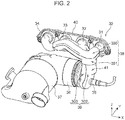
FIG. 2 is a schematic perspective view illustrating the configuration of the exhaust device. -
FIG. 3 is a schematic plan view illustrating a configuration of exhaust pipes. -
FIG. 4 is a schematic expanded view illustrating an internal configuration of the exhaust pipes. -
FIG. 5 is a schematic cross-sectional view illustrating the internal configuration of the exhaust pipes. - In the following, an embodiment of the present invention is described with reference to the drawings. The embodiment described in the following is one example according to the present invention. The present invention is not limited by the following embodiment except for an essential configuration thereof.
- An embodiment is described with reference to the drawings. In each of the drawings, X direction indicates a cylinder array direction of an engine, Y direction indicates a width direction of the engine, and Z direction indicates an up-down direction of the engine.
- An overall configuration of an
engine body 1 and anexhaust device 3 according to the present embodiment is described with reference toFIGS. 1 to 3 . - As illustrated in
FIG. 1 , theengine body 1 is an in-line 4-cylinder gasoline engine. In theengine body 1, a #1cylinder 11, a #2cylinder 12, a #3cylinder 13, and a #4cylinder 14 are arranged in this order from the left side in the X direction. In the present embodiment, an ignition order in theengine body 1 is the order: the #1cylinder 11 → the #3cylinder 13 → the #4cylinder 14 → the #2cylinder 12. - In
FIG. 1 , a cylinder head of theengine body 1 is viewed from above. An upper side in the Y direction is a vehicle front side, and a lower side in the Y direction is a vehicle rear side. - In the
engine body 1,intake pipes 21 to 24 are connected to intake ports of thecylinders 11 to 14. Theintake pipes 21 to 24 are, in order from the right side in the X direction, the #1intake pipe 21, the #2intake pipe 22, the #3intake pipe 23, and the #4intake pipe 24. - The
exhaust device 3 is connected to the exhaust side of theengine body 1. As illustrated inFIGS. 1 and2 , theexhaust device 3 includes anexhaust pipe 30 and anengagement flange 40. Theexhaust pipe 30 is comprised of #1 to #4exhaust pipes 31 to 34 connected to exhaust ports of thecylinders 11 to 14. - The #2
exhaust pipe 32 and the #3exhaust pipe 33 are comprised of atubular member 41 formed by a plurality ofmembers 300 to 303, which are press-worked plate members. As illustrated inFIG. 2 , thetubular member 41 includes a mergingtubular portion 38 formed by the merging tubularupper member 300 and the merging tubularlower member 301; and a downstreamtubular portion 39 formed by the downstreamtubular member 302 and the downstreamtubular member 303. The mergingtubular portion 38 is formed by joining end peripheries of the mergingtubular member 300 and the mergingtubular member 301 by welding or the like. Likewise, the downstreamtubular portion 39 is formed by joining end peripheries of the downstreamtubular member 302 and the downstreamtubular member 303 by welding or the like. - Exhaust gas discharged through an exhaust passage of the #2
exhaust pipe 32 and exhaust gas discharged through an exhaust passage of the #3exhaust pipe 33 are merged inside the mergingtubular portion 38. Then, the merged exhaust gas flows to the downstreamtubular portion 39 through a communication openingportion 301d. - Each of the #1
exhaust pipe 31 and the #4exhaust pipe 34 is comprised of a pipe member, and is bent into a predetermined shape. Further, distal ends of the #1exhaust pipe 31 and the #4exhaust pipe 34 are received in thetubular member 41 formed by themembers 300 to 303. - In the
exhaust device 3 according to the present embodiment, the downstreamtubular portion 39 is disposed in such a way as to be offset on the side of the #1 cylinder 11 (right side inFIG. 1 ) with respect to a center CLi of a cylinder array in theengine body 1 in the X direction. In other words, the downstreamtubular portion 39 is disposed in an offset manner in an area associated with the #1cylinder 11 in the X direction. The downstreamtubular potion 39 is disposed vertically in such a way as to substantially align with the Z direction in the area associated with the #1cylinder 11 in the X direction. - As illustrated in
FIG. 2 , a distal end of an O2 sensor 35 is received in a lower portion in the Z direction from the right side in the X direction. Further, acatalyst 36 being an exhaust gas purification device is connected to the downstreamtubular portion 39 on a downstream side in a flow direction of exhaust gas. Thecatalyst 36 has a substantially cylindrical shape as an external appearance, and is disposed in such a way as to extend in the X direction on a lower side of the mergingtubular portion 38 in the Z direction. - The
catalyst 36 is connected to a gasoline particulate filter (GPF) 37 at a left end thereof in the X direction. - The
engagement flange 40 engages theexhaust pipe 30 of theexhaust device 3 to a cylinder block of theengine body 1. As illustrated inFIG. 3 , distal ends of theexhaust pipes 31 to 34 are received in theengagement flange 40, and port-side opening portions 31a to 34a face the exhaust ports of theengine body 1. Theexhaust pipes 31 to 34 are airtightly connected to the exhaust ports of theengine body 1 by theengagement flange 40. - In the present embodiment, the
exhaust pipe 30 is supported in a cantilever state by a portion engaged to the cylinder block by using theengagement flange 40. - An internal configuration of the
exhaust pipe 30 of theexhaust device 3 is described with reference toFIGS. 4 and5 .FIG. 4 is a schematic developed view illustrating theexhaust pipe 30 except for the merging tubularupper member 300.FIG. 5 is a schematic cross-sectional view in which theexhaust pipe 30 is partially cut away. - As illustrated in
FIG. 4 , a #2exhaust groove portion 301a is formed in the merging tubularlower member 301 constituting the mergingtubular portion 38 at a position associated with the #2exhaust pipe 32, and a #3exhaust groove portion 301b is formed at a position associated with the #3exhaust pipe 33. Further, the #2exhaust groove portion 301a communicates with the port-side opening portion 32a, and the #3exhaust groove portion 301b communicates with the port-side opening portion 33a. - In
FIG. 4 , although illustration is omitted, the merging tubularupper member 300 is formed by press working in such a way as to be substantially symmetrical to the merging tubularlower member 301. Further, a jointperipheral portion 301c is formed on an outer periphery of the merging tubularlower member 301, and a joint peripheral portion is also formed on an outer periphery of the merging tubularupper member 300. The merging tubularupper member 300 and the merging tubularlower member 301 are airtightly joined to each other by the jointperipheral portions 301c. - As illustrated in
FIG. 4 , a portion where the #2exhaust groove portion 301a and the #3exhaust groove portion 301b intersect with each other, in other words, a mergingportion 38a where exhaust gas from the #2exhaust pipe 32 and exhaust gas from the #3exhaust pipe 33 are merged is formed in an area on a side of the #4 cylinder 14 (left side inFIG. 4 ) in the X direction with respect to a position where thecommunication opening portion 301d is formed. - As illustrated in
FIGS. 4 and5 , the #1exhaust pipe 31 extends in the Y direction, and is bent in the Z direction at a position where thecommunication opening portion 301d is formed. Adistal end 31c of the #1exhaust pipe 31 is disposed at a position inside the downstreamtubular portion 39 on a lower side in the Z direction with respect to thecommunication opening portion 301d. Thedistal end 31c of the #1exhaust pipe 31 is slightly bent toward a side (rightwardly inFIG. 5 ) opposite to the #4cylinder 14 in the X direction with respect to an axis aligned with the Z direction. Further, a distal-side opening portion 31b of the #1cylinder 31 faces ashelf portion 39c, which is formed on a portion (right side portion inFIG. 5 ) of the downstreamtubular portion 39 on a side opposite to the #4cylinder 14 in the X direction. - The #4
exhaust pipe 34 is curved into a U-shape or a V-shape with a downwardly projecting shape (curved portion 34c) in the Z direction on an outer portion of the mergingtubular portion 38, and is curved into a U-shape or a V-shape with an upwardly projecting shape (curved portion 34d) in the Z direction on an inner portion of the mergingtubular portion 38. Adistal end 34e of the #4exhaust pipe 34 is disposed in such a way that a distal-side opening portion 34b faces a wall surface of the #1exhaust pipe 31. - As illustrated in
FIG. 4 , thedistal end 34e of the #4exhaust pipe 34 is disposed on the side of thecommunication opening portion 301d with respect to the mergingportion 38a where exhaust gas from the #2exhaust pipe 32 and exhaust gas from the #3exhaust pipe 33 are merged. Specifically, thedistal end 34e of the #4exhaust pipe 34 extends to a position close to thecommunication opening portion 301d with respect to the mergingportion 38a. - As illustrated in
FIG. 5 , a catalyst-side opening portion 39a for connecting thecatalyst 36 is formed in the downstreamtubular portion 39. The catalyst-side opening portion 39a is formed in such a way as to face the left side in the X direction. - A
sensor mounting portion 39b for mounting the O2 sensor 35 is formed on a wall portion of the downstreamtubular portion 39 on the right side in the X direction. The O2 sensor 35 is disposed inside the downstreamtubular portion 39 through thesensor mounting portion 39b. - The
shelf portion 39c of the downstreamtubular portion 39 is formed at a position between the distal-side opening portion 31b of the #1exhaust pipe 31, and thesensor mounting portion 39b in the Z direction. - In the
exhaust device 3 according to the present embodiment, thefirst exhaust pipe 31 is formed by using a pipe member, and thesecond exhaust pipe 32 and thethird exhaust pipe 33 are comprised of the tubular member 41 (a member formed by the four press-workedplate members 300 to 303). Therefore, as compared with a case where all the exhaust pipes are formed by pipe members, or conversely, a case where all the exhaust pipes are comprised of one tubular member, it is possible to miniaturize theexhaust device 3. - When all the exhaust pipes are formed by pipe members, it is difficult to miniaturize the exhaust device as described in the above aspect, due to constraints in terms of production such as bending or welding a pipe member.
- Further, when an exhaust pipe is comprised of a tubular member, it is difficult to miniaturize the exhaust device, when all the exhaust pipes are formed by one tubular member, since it is difficult to form a sharp bent portion of the pipe. Furthermore, when a plurality of exhaust pipes are comprised of a tubular member, it is also difficult to miniaturize the exhaust device, when all the exhaust pipes are comprised of one tubular member, since it is necessary to secure a width of a partition portion for separating the exhaust pipes one from another to some extent.
- Further, in the
exhaust device 3 according to the present embodiment, since thedistal end 31c of thefirst exhaust pipe 31 is disposed at a position inside the downstreamtubular portion 39, exhaust interference at least between exhaust gas to be discharged through thefirst exhaust pipe 31, and exhaust gas to be discharged through thesecond exhaust pipe 32 or thethird exhaust pipe 33 is suppressed. Specifically, since thedistal end 31c of thefirst exhaust pipe 31 extends to a position inside the downstreamtubular portion 39 on a downstream side in a flow direction of exhaust gas with respect to the mergingtubular portion 38a where exhaust gas flowing through thesecond exhaust pipe 32 and exhaust gas flowing through thethird exhaust pipe 33 are merged, it is possible to suppress exhaust interference. - Therefore, the
exhaust device 3 according to the present embodiment is able to suppress exhaust interference, while satisfying a demand for miniaturization. - Further, in the
exhaust device 3 according to the present embodiment, thefourth exhaust pipe 34 connected to an exhaust port of thefourth cylinder 14 is also comprised of a pipe member, and thedistal end 34e of thefourth exhaust pipe 34 is received in the mergingtubular portion 38 of thetubular member 41. Therefore, an exhaust device for an engine according to the present embodiment is able to secure a pipe length of thefourth exhaust pipe 34. - Further, in the present embodiment, as compared with a case where the fourth exhaust pipe is integrally formed with a tubular member, it is possible to miniaturize the
exhaust device 3. - In the
exhaust device 3 according to the present embodiment, since an exhaust passage of the fourth exhaust pipe, and an exhaust passage of thethird exhaust pipe 33 are separated by a pipe wall constituting thefourth exhaust pipe 34, as compared with a case where the exhaust passages are separated by a plate member constituting the mergingtubular portion 38, it is possible to further miniaturize theexhaust device 3. - In the
exhaust device 3 according to the present embodiment, an in-line 4-cylinder gasoline engine is employed, and an ignition order is the order: thefirst cylinder 11 → thethird cylinder 13 → thefourth cylinder 14 → thesecond cylinder 12. In an engine as described above, since thedistal end 34e of thefourth exhaust pipe 34 is disposed on the side of thecommunication opening portion 301d with respect to the mergingportion 38a of the mergingtubular portion 38 where exhaust gas from thesecond exhaust pipe 32 and exhaust gas from thethird exhaust pipe 33 are merged, it is possible to securely suppress exhaust interference. - In the
exhaust device 3 according to the present embodiment, the downstreamtubular portion 39 is disposed in such a way as to be offset on the side of thefirst cylinder 11 with respect to the center CLi of a cylinder array in the X-direction, and thecatalyst 36 to be connected to the downstreamtubular portion 39 is disposed in such a way as to extend along the cylinder array direction (X direction) on a lower side of the mergingtubular portion 38 in the Z direction. Therefore, it is possible to further miniaturize theexhaust device 3. - In the embodiment, an in-line 4-cylinder gasoline engine is employed as one example of the
engine body 1. The present invention, however, is not limited to the above. For example, as a type of the engine, it is also possible to employ a diesel engine. - Further, the number of cylinders of the engine may be three, or five or more. In this case, the configuration number of exhaust pipes may be in conformity with the number of cylinders.
- Further, a pattern of an engine is not limited to an in-line pattern, and a V-type engine or a W-type engine may be employed.
- Further, in the embodiment, a configuration in which the downstream
tubular portion 39 of thetubular member 41 is offset on the side of the #1cylinder 11 with respect to the center CL1 of the cylinder array in the X direction (cylinder array direction) is employed as one example. The present invention, however, is not limited to the above. For example, the downstreamtubular portion 39 of a tubular member may be disposed in such a way as to be offset on the side of the #4cylinder 14, which is opposite to the #1cylinder 11 with respect to the center CL1 of the cylinder array in the X direction (cylinder array direction). - Further, in the embodiment, the
tubular member 41 is comprised of four plate members (the merging tubularupper member 300, the merging tubularlower member 301, the downstreamtubular member 302, and the downstream tubular member 303). The present invention, however, is not limited to the above. For example, each of the merging tubularupper member 300 and the merging tubularlower member 301 constituting the mergingtubular portion 38 may be extended, and a downstream tubular portion may be formed by the extended portions. Specifically, a tubular member comprised of a merging tubular portion and a downstream tubular portion may be comprised of combining two press-worked plate members. When such a modification is employed, it is possible to integrally form a tubular member comprised of a merging tubular portion and a downstream tubular portion by two plate members. Therefore, it is possible to reduce the number of parts, and suppress cumbersome parts management during production. Further, when the above modification is employed, as compared with a case where a merging tubular portion and a downstream tubular portion are formed as individual parts, by integrally forming a merging tubular portion and a downstream tubular portion, it is possible to reduce the number of steps such as joining the merging tubular portion and the downstream tubular portion, and reduce the production cost. - Further, it is possible to set the number of plate members constituting a tubular member to five or more.
- Further, in the embodiment, all the four plate members (the merging tubular
upper member 300, the merging tubularlower member 301, the downstreamtubular member 302, and the downstream tubular member 303) are subjected to press working. The present invention, however, is not limited to the above. For example, it is possible to comprise of a merging tubular portion and a downstream tubular portion by combining a press-worked plate member, and a flat plate member which has not undergone press working. - Further, in the embodiment, the entirety of the
tubular member 41 is comprised of combining four plate members. The present invention, however, is not limited to the above. For example, only a merging tubular portion among constituent elements of a tubular member may be comprised of combining a plurality of plate members, and a downstream tubular portion may be formed by a pipe member or the like. - Further, in the embodiment, as described with reference to
FIG. 5 , two portions, namely, thecurved portions exhaust pipe 34 where the #4exhaust pipe 34 is received in the mergingtubular portion 38. The present invention, however, is not limited to the above. When it is not necessary to set a pipe length long, it is also possible to form the #4 exhaust pipe in such a way as to extend linearly. - Further, in the embodiment, the
distal end 34e of the #4exhaust pipe 34 is present inside the mergingtubular portion 38. The present invention, however, is not limited to the above. It is also possible to employ a configuration in which the #4 exhaust pipe extends to a position of a downstream tubular portion through a communication opening portion, depending on the length of the #4 exhaust pipe. - An exhaust device for an engine according to one aspect of the present invention is an exhaust device connected to an exhaust port of an engine in which a plurality of cylinders are arranged in series. The exhaust device includes: a first exhaust pipe connected to an exhaust port of a first cylinder, among the plurality of the cylinders, disposed at one end in the array direction; and a second exhaust pipe connected to an exhaust port of a second cylinder, and a third exhaust pipe connected to an exhaust port of a third cylinder, the second cylinder and the third cylinder among the plurality of the cylinders following the first cylinder in the array direction. The second exhaust pipe and the third exhaust pipe are comprised of a tubular member including a merging tubular portion in which exhaust gas from the exhaust port of the second cylinder and exhaust gas from the exhaust port of the third cylinder are merged; and a downstream tubular portion continued to the merging tubular portion via a communication opening portion, and formed on a downstream side in a flow direction of the exhaust gas. The first exhaust pipe is comprised of a pipe member. The merging tubular portion is comprised of combining a plurality of plate members, at least a part of which is formed by press working. The downstream tubular portion is disposed in such a way as to be offset on a side of the one end with respect to a center of the plurality of the cylinder in the array direction. A distal end of the first exhaust pipe is disposed inside the downstream tubular portion through the communication opening portion.
- In the exhaust device for the engine according to the above aspect, the first exhaust pipe is formed by using a pipe member, the second exhaust pipe and the third exhaust pipe are comprised of the tubular member, and the merging tubular portion of the tubular member is comprised of a member formed by a plurality of plate members, at least a part of which is formed by press working. Therefore, as compared with a case where all the exhaust pipes are formed by pipe members, or conversely, a case where all the exhaust pipes are comprised of a member comprised of combining a plurality of plate members, the above configuration is advantageous in miniaturizing the exhaust device.
- When all the exhaust pipes are formed by pipe members, it is difficult to miniaturize the exhaust device as described in the above aspect, due to constraints in terms of production such as bending or welding a pipe member.
- Further, when all the exhaust pipes are comprised of a member comprised of combining a plurality of plate members, it is difficult to miniaturize the exhaust device, when all the exhaust pipes are formed by a member comprised of combining a plurality of plate members, since it is difficult to form a sharp bent portion of a pipe. Furthermore, when all the exhaust pipes are comprised of a member comprised of combining a plurality of plate members, it is also difficult to miniaturize the exhaust device, when all the exhaust pipes are comprised of one tubular member, since it is necessary to secure a width of a partition portion for separating the exhaust pipes one from another to some extent.
- Further, in the exhaust device for the engine according to the above aspect, exhaust interference at least between exhaust gas to be discharged through the first exhaust pipe, and exhaust gas to be discharged through the second exhaust pipe or the third exhaust pipe is suppressed, since the distal end of the first exhaust pipe is disposed inside the downstream tubular portion. Specifically, since the distal end of the first exhaust pipe extends to a position of the downstream tubular portion on a downstream side in a flow direction of exhaust gas with respect to the merging tubular portion where exhaust gas from the second exhaust pipe and exhaust gas from the third exhaust pipe are merged, it is possible to suppress exhaust interference.
- Therefore, the exhaust device for the engine according to the above aspect is advantageous in suppressing exhaust interference, while satisfying a demand for miniaturization.
- The exhaust device for the engine according to the above aspect may further include an other-end exhaust pipe connected to an exhaust port of an other-end cylinder among the plurality of the cylinders, the other-end cylinder being disposed on the other end in the array direction. The other-end exhaust pipe may be comprised of a pipe member, and a distal end of the other-end exhaust pipe may be received inside the tubular member.
- In the exhaust device for the engine employing the above configuration, the other-end exhaust pipe connected to the exhaust port of the other-end cylinder, among the plurality of the cylinders, disposed on the other end (side opposite to the first cylinder) in a cylinder array direction (the above-described array direction) is also comprised of a pipe member. The distal end of the other-end exhaust pipe is received in the tubular member. Therefore, the exhaust device for the engine according to the above aspect is advantageous in securing a pipe length of the other-end exhaust pipe.
- Further, in the above aspect, as compared with a case where the other-end exhaust pipe is integrally formed with the tubular member, it is possible to miniaturize the exhaust device.
- In the exhaust device for the engine according to the above aspect, an exhaust passage of the other-end exhaust pipe, and an exhaust passage of at least one of the second exhaust pipe and the third exhaust pipe may be separated by a pipe wall constituting the other-end exhaust pipe inside the merging tubular portion.
- In the exhaust device for the engine employing the above configuration, the exhaust passage of the other-end exhaust pipe, and the exhaust passage of at least one of the second exhaust pipe and the third exhaust pipe are separated by the pipe wall constituting the other-end exhaust pipe. Therefore, as compared with a case where the exhaust passages are separated by a plate member constituting the merging tubular portion (tubular member), the above configuration is further advantageous in miniaturizing the exhaust device.
- In the exhaust device for the engine according to the above aspect, the engine may be a 4-cylinder gasoline engine. An ignition order of the engine may be an order from the first cylinder, the third cylinder, the fourth cylinder, and the second cylinder. An opening of the distal end of the other-end exhaust pipe may be formed on a side of the communication opening portion of the merging tubular portion with respect to a position where exhaust gas from the exhaust port of the second cylinder and exhaust gas from the exhaust port of the third cylinder are merged.
- In the exhaust device for the engine employing the above configuration, a 4-cylinder gasoline engine is employed as the engine, and the ignition order is an order from the first cylinder, the third cylinder, the fourth cylinder, and the second cylinder. In an engine as described above, the distal end of the other-end exhaust pipe (fourth exhaust pipe) is disposed on the side of the communication opening portion with respect to a portion of the merging tubular portion where exhaust gas from the exhaust port of the second cylinder and exhaust gas from the exhaust port of the third cylinder are merged. Therefore, it is possible to securely suppress exhaust interference.
- In the exhaust device for the engine according to the above aspect, the downstream tubular portion may be comprised of combining a plurality of plate members, at least a part of which is formed by press working.
- When the above configuration is employed, configuring the downstream tubular portion by combining a plurality of plate members is further advantageous in miniaturizing the exhaust device.
- In the exhaust device for the engine according to the above aspect, the downstream tubular portion may be integrally formed with the merging tubular portion by the plurality of the plate members.
- In the exhaust device for the engine employing the above configuration, since the merging tubular portion and the downstream tubular portion are integrally formed by the plurality of the plate members, it is possible to reduce the number of parts, and avoid cumbersome parts management during production. Further, in the exhaust device for the engine employing the above configuration, by integrally forming the merging tubular portion and the downstream tubular portion, it is possible to reduce the number of steps such as joining, as compared with a case where respective portions are formed as individual parts, and then, are joined to one another. Therefore, the exhaust device for the engine according to the above aspect is advantageous in reducing the production cost.
- In the exhaust device for the engine according to the above aspect, an exhaust gas purification device may be connected to the downstream tubular portion on a downstream side in a flow direction of exhaust gas, and the exhaust gas purification device may be disposed in such a way as to extend along the array direction on a lower side of the first exhaust pipe, the second exhaust pipe, and the third exhaust pipe.
- In the exhaust device for the engine employing the above configuration, the downstream tubular portion is disposed in such a way as to be offset on the side of the one end (side of the first cylinder), and the exhaust gas purification device to be connected to the downstream tubular portion is disposed in such a way as to extend along a cylinder array direction (the above-described array direction) on a lower side of the merging tubular portion. This is further advantageous in miniaturing the exhaust device.
- As described above, each of the exhaust devices is able to suppress exhaust interference, while satisfying a demand for miniaturization.
Claims (7)
- An exhaust device for an engine, the exhaust device being connected to an exhaust port of the engine in which a plurality of cylinders are arranged in series, the exhaust device comprising:a first exhaust pipe connected to an exhaust port of a first cylinder, among the plurality of the cylinders, disposed at one end in the array direction; anda second exhaust pipe connected to an exhaust port of a second cylinder, and a third exhaust pipe connected to an exhaust port of a third cylinder, the second cylinder and the third cylinder among the plurality of the cylinders following the first cylinder in the array direction, whereinthe second exhaust pipe and the third exhaust pipe are comprised of a tubular member including a merging tubular portion where exhaust gas from the exhaust port of the second cylinder and exhaust gas from the exhaust port of the third cylinder are merged inside; and a downstream tubular portion continued to the merging tubular portion via a communication opening portion, and formed on a downstream side in a flow direction of the exhaust gas,the first exhaust pipe is comprised of a pipe member,the merging tubular portion is comprised of combining a plurality of plate members, at least a part of which is formed by press working,the downstream tubular portion is disposed in such a way as to be offset on a side of the one end with respect to a center of the plurality of the cylinders in the array direction, anda distal end of the first exhaust pipe is disposed inside the downstream tubular portion through the communication opening portion.
- The exhaust device for the engine according to claim 1, further comprising
an other-end exhaust pipe connected to an exhaust port of an other-end cylinder among the plurality of the cylinders, the other-end cylinder being disposed on the other end in the array direction, wherein
the other-end exhaust pipe is comprised of a pipe member, and
a distal end of the other-end exhaust pipe is received inside the tubular member. - The exhaust device for the engine according to claim 2, wherein
an exhaust passage of the other-end exhaust pipe, and an exhaust passage of at least one of the second exhaust pipe and the third exhaust pipe are separated by a pipe wall constituting the other-end exhaust pipe inside the merging tubular portion. - The exhaust device for the engine according to claim 2 or 3, wherein
the engine is a 4-cylinder gasoline engine,
an ignition order of the engine is an order from the first cylinder, the third cylinder, the fourth cylinder, and the second cylinder, and
an opening of the distal end of the other-end exhaust pipe is formed on a side of the communication opening portion of the merging tubular portion with respect to a position where exhaust gas from the exhaust port of the second cylinder and exhaust gas from the exhaust port of the third cylinder are merged. - The exhaust device for the engine according to any one of claims 1 to 4, wherein
the downstream tubular portion is comprised of combining a plurality of plate members, at least a part of which is formed by press working. - The exhaust device for the engine according to claim 5, wherein
the downstream tubular portion is integrally formed with the merging tubular portion by the plurality of the plate members. - The exhaust device for the engine according to any one of claims 1 to 6, wherein
an exhaust gas purification device is connected to the downstream tubular portion on a downstream side in a flow direction of exhaust gas. and
the exhaust gas purification device is disposed in such a way as to extend along the array direction on a lower side of the first exhaust pipe, the second exhaust pipe, and the third exhaust pipe.
Applications Claiming Priority (2)
| Application Number | Priority Date | Filing Date | Title |
|---|---|---|---|
| JP2017142793A JP6493464B2 (en) | 2017-07-24 | 2017-07-24 | Engine exhaust system |
| PCT/JP2018/026893 WO2019021905A1 (en) | 2017-07-24 | 2018-07-18 | Exhaust device for engine |
Publications (3)
| Publication Number | Publication Date |
|---|---|
| EP3640446A1 true EP3640446A1 (en) | 2020-04-22 |
| EP3640446A4 EP3640446A4 (en) | 2020-06-03 |
| EP3640446B1 EP3640446B1 (en) | 2021-04-21 |
Family
ID=65039629
Family Applications (1)
| Application Number | Title | Priority Date | Filing Date |
|---|---|---|---|
| EP18838380.6A Active EP3640446B1 (en) | 2017-07-24 | 2018-07-18 | Exhaust device for engine |
Country Status (5)
| Country | Link |
|---|---|
| US (1) | US11149620B2 (en) |
| EP (1) | EP3640446B1 (en) |
| JP (1) | JP6493464B2 (en) |
| CN (1) | CN110892138B (en) |
| WO (1) | WO2019021905A1 (en) |
Family Cites Families (22)
| Publication number | Priority date | Publication date | Assignee | Title |
|---|---|---|---|---|
| US4197704A (en) * | 1976-06-11 | 1980-04-15 | Honda Giken Kogyo Kabushiki Kaisha | Exhaust manifold for internal combustion engine |
| JPS59165521U (en) * | 1983-04-19 | 1984-11-06 | スズキ株式会社 | Collective exhaust chamber of 4-cylinder engine |
| JPS63130618U (en) * | 1987-02-20 | 1988-08-26 | ||
| JPH06229249A (en) * | 1993-01-30 | 1994-08-16 | Suzuki Motor Corp | Exhaust manifold structure of turbocharger engine |
| JPH0968040A (en) | 1995-09-04 | 1997-03-11 | Sankei Kogyo Kk | Clamshell type manifold |
| US5816044A (en) * | 1997-09-26 | 1998-10-06 | Biggs; Gary L. | Header assembly for internal combustion engines |
| US6230490B1 (en) * | 1998-11-09 | 2001-05-15 | Suzuki Motor Corp. | Exhaust manifold for internal combustion engines |
| JP3452528B2 (en) | 2000-04-03 | 2003-09-29 | フタバ産業株式会社 | Exhaust manifold |
| JP3791419B2 (en) * | 2002-01-17 | 2006-06-28 | 日産自動車株式会社 | Exhaust device for internal combustion engine |
| JP2005036724A (en) | 2003-07-15 | 2005-02-10 | Yumex Corp | Exhaust manifold |
| EP1803909B2 (en) * | 2003-12-01 | 2018-07-04 | Nissan Motor Co., Ltd. | Exhaust manifold for internal combusion engine |
| FR2863307B1 (en) * | 2003-12-04 | 2006-02-24 | Renault Sas | ENGINE EQUIPPED WITH EXHAUST MANIFOLD WHOSE OUTPUT CIRCUIT HAS A CONNECTING DRIVING |
| DE112005000653A5 (en) * | 2004-03-25 | 2008-07-24 | Avl List Gmbh | Exhaust system for an internal combustion engine |
| JP4428286B2 (en) * | 2005-05-17 | 2010-03-10 | トヨタ自動車株式会社 | Exhaust gas purification device for internal combustion engine |
| FR2946086A1 (en) * | 2009-06-02 | 2010-12-03 | Peugeot Citroen Automobiles Sa | Exhaust manifold for supercharged combustion engine, has two parts connected to groups of cylinders of engine, respectively and forming single outlet, where first part is made of cast iron and second part is made of steel |
| JP2011116204A (en) * | 2009-12-02 | 2011-06-16 | Mazda Motor Corp | Exhaust system of transverse engine |
| JP4941543B2 (en) * | 2009-12-02 | 2012-05-30 | マツダ株式会社 | Horizontal engine exhaust system |
| JP5890257B2 (en) | 2012-06-06 | 2016-03-22 | フタバ産業株式会社 | Exhaust system parts |
| JP6356413B2 (en) * | 2013-12-13 | 2018-07-11 | フタバ産業株式会社 | Catalytic converter |
| WO2016035154A1 (en) * | 2014-09-03 | 2016-03-10 | 日産自動車株式会社 | Exhaust device for internal combustion engine |
| JP6405806B2 (en) | 2014-09-03 | 2018-10-17 | 日産自動車株式会社 | Exhaust device for internal combustion engine |
| JP6256275B2 (en) | 2014-09-24 | 2018-01-10 | マツダ株式会社 | Engine intake / exhaust system |
-
2017
- 2017-07-24 JP JP2017142793A patent/JP6493464B2/en active Active
-
2018
- 2018-07-18 EP EP18838380.6A patent/EP3640446B1/en active Active
- 2018-07-18 CN CN201880045339.XA patent/CN110892138B/en not_active Expired - Fee Related
- 2018-07-18 WO PCT/JP2018/026893 patent/WO2019021905A1/en not_active Ceased
- 2018-07-18 US US16/630,936 patent/US11149620B2/en active Active
Also Published As
| Publication number | Publication date |
|---|---|
| US20200232374A1 (en) | 2020-07-23 |
| EP3640446B1 (en) | 2021-04-21 |
| US11149620B2 (en) | 2021-10-19 |
| WO2019021905A1 (en) | 2019-01-31 |
| CN110892138A (en) | 2020-03-17 |
| JP2019023446A (en) | 2019-02-14 |
| CN110892138B (en) | 2021-11-05 |
| JP6493464B2 (en) | 2019-04-03 |
| EP3640446A4 (en) | 2020-06-03 |
Similar Documents
| Publication | Publication Date | Title |
|---|---|---|
| JP4496248B2 (en) | Supercharged engine with EGR device | |
| EP3640446B1 (en) | Exhaust device for engine | |
| CN102782277B (en) | Exhaust manifold | |
| JP2021004569A (en) | Egr gas distribution device | |
| US7297174B2 (en) | Particulate filter assembly | |
| CN110017218B (en) | internal combustion engine | |
| KR101196305B1 (en) | Exhaust manifold | |
| JP4760526B2 (en) | Cylinder head of internal combustion engine | |
| JP2008285999A (en) | Intake manifold | |
| JP2019023447A (en) | Exhaust system for engine | |
| WO2008127684A2 (en) | Cylinder head | |
| JPH09222052A (en) | Intake manifold | |
| JP2013217288A (en) | Exhaust port structure for internal combustion engine | |
| JPH10122071A (en) | V-type engine | |
| KR100418801B1 (en) | Assembly of exhaust manifold for internal combustion engine | |
| US20170037765A1 (en) | Exhaust Manifold | |
| JP2560393Y2 (en) | Multi-cylinder V-type engine intake system | |
| KR101745205B1 (en) | Exhaust manifold structure of vehicle engine | |
| JPH06147040A (en) | Intake system in multicylinder internal combustion engine | |
| JP2001342892A (en) | Intake device for multi-cylinder internal combustion engine | |
| JPH0968040A (en) | Clamshell type manifold | |
| JP2005233045A (en) | Exhaust manifold | |
| JPS5910339Y2 (en) | Exhaust purification device | |
| IT202300000168A1 (en) | “INTERNAL COMBUSTION ENGINE WITH DISLOCATED EGR HEAT EXCHANGER” | |
| JPH09222014A (en) | Exhaust manifold with catalyst |
Legal Events
| Date | Code | Title | Description |
|---|---|---|---|
| STAA | Information on the status of an ep patent application or granted ep patent |
Free format text: STATUS: THE INTERNATIONAL PUBLICATION HAS BEEN MADE |
|
| PUAI | Public reference made under article 153(3) epc to a published international application that has entered the european phase |
Free format text: ORIGINAL CODE: 0009012 |
|
| STAA | Information on the status of an ep patent application or granted ep patent |
Free format text: STATUS: REQUEST FOR EXAMINATION WAS MADE |
|
| 17P | Request for examination filed |
Effective date: 20200116 |
|
| AK | Designated contracting states |
Kind code of ref document: A1 Designated state(s): AL AT BE BG CH CY CZ DE DK EE ES FI FR GB GR HR HU IE IS IT LI LT LU LV MC MK MT NL NO PL PT RO RS SE SI SK SM TR |
|
| AX | Request for extension of the european patent |
Extension state: BA ME |
|
| A4 | Supplementary search report drawn up and despatched |
Effective date: 20200504 |
|
| RIC1 | Information provided on ipc code assigned before grant |
Ipc: F01N 13/18 20100101ALI20200424BHEP Ipc: F01N 13/10 20100101AFI20200424BHEP Ipc: F01N 3/10 20060101ALI20200424BHEP Ipc: F01N 3/24 20060101ALI20200424BHEP |
|
| DAV | Request for validation of the european patent (deleted) | ||
| DAX | Request for extension of the european patent (deleted) | ||
| GRAP | Despatch of communication of intention to grant a patent |
Free format text: ORIGINAL CODE: EPIDOSNIGR1 |
|
| STAA | Information on the status of an ep patent application or granted ep patent |
Free format text: STATUS: GRANT OF PATENT IS INTENDED |
|
| INTG | Intention to grant announced |
Effective date: 20201207 |
|
| GRAS | Grant fee paid |
Free format text: ORIGINAL CODE: EPIDOSNIGR3 |
|
| GRAA | (expected) grant |
Free format text: ORIGINAL CODE: 0009210 |
|
| STAA | Information on the status of an ep patent application or granted ep patent |
Free format text: STATUS: THE PATENT HAS BEEN GRANTED |
|
| AK | Designated contracting states |
Kind code of ref document: B1 Designated state(s): AL AT BE BG CH CY CZ DE DK EE ES FI FR GB GR HR HU IE IS IT LI LT LU LV MC MK MT NL NO PL PT RO RS SE SI SK SM TR |
|
| REG | Reference to a national code |
Ref country code: GB Ref legal event code: FG4D |
|
| REG | Reference to a national code |
Ref country code: CH Ref legal event code: EP |
|
| REG | Reference to a national code |
Ref country code: DE Ref legal event code: R096 Ref document number: 602018015996 Country of ref document: DE |
|
| REG | Reference to a national code |
Ref country code: IE Ref legal event code: FG4D |
|
| REG | Reference to a national code |
Ref country code: AT Ref legal event code: REF Ref document number: 1384852 Country of ref document: AT Kind code of ref document: T Effective date: 20210515 |
|
| REG | Reference to a national code |
Ref country code: LT Ref legal event code: MG9D |
|
| REG | Reference to a national code |
Ref country code: AT Ref legal event code: MK05 Ref document number: 1384852 Country of ref document: AT Kind code of ref document: T Effective date: 20210421 |
|
| REG | Reference to a national code |
Ref country code: NL Ref legal event code: MP Effective date: 20210421 |
|
| PG25 | Lapsed in a contracting state [announced via postgrant information from national office to epo] |
Ref country code: FI Free format text: LAPSE BECAUSE OF FAILURE TO SUBMIT A TRANSLATION OF THE DESCRIPTION OR TO PAY THE FEE WITHIN THE PRESCRIBED TIME-LIMIT Effective date: 20210421 Ref country code: LT Free format text: LAPSE BECAUSE OF FAILURE TO SUBMIT A TRANSLATION OF THE DESCRIPTION OR TO PAY THE FEE WITHIN THE PRESCRIBED TIME-LIMIT Effective date: 20210421 Ref country code: HR Free format text: LAPSE BECAUSE OF FAILURE TO SUBMIT A TRANSLATION OF THE DESCRIPTION OR TO PAY THE FEE WITHIN THE PRESCRIBED TIME-LIMIT Effective date: 20210421 Ref country code: NL Free format text: LAPSE BECAUSE OF FAILURE TO SUBMIT A TRANSLATION OF THE DESCRIPTION OR TO PAY THE FEE WITHIN THE PRESCRIBED TIME-LIMIT Effective date: 20210421 Ref country code: AT Free format text: LAPSE BECAUSE OF FAILURE TO SUBMIT A TRANSLATION OF THE DESCRIPTION OR TO PAY THE FEE WITHIN THE PRESCRIBED TIME-LIMIT Effective date: 20210421 Ref country code: BG Free format text: LAPSE BECAUSE OF FAILURE TO SUBMIT A TRANSLATION OF THE DESCRIPTION OR TO PAY THE FEE WITHIN THE PRESCRIBED TIME-LIMIT Effective date: 20210721 |
|
| PG25 | Lapsed in a contracting state [announced via postgrant information from national office to epo] |
Ref country code: LV Free format text: LAPSE BECAUSE OF FAILURE TO SUBMIT A TRANSLATION OF THE DESCRIPTION OR TO PAY THE FEE WITHIN THE PRESCRIBED TIME-LIMIT Effective date: 20210421 Ref country code: PL Free format text: LAPSE BECAUSE OF FAILURE TO SUBMIT A TRANSLATION OF THE DESCRIPTION OR TO PAY THE FEE WITHIN THE PRESCRIBED TIME-LIMIT Effective date: 20210421 Ref country code: NO Free format text: LAPSE BECAUSE OF FAILURE TO SUBMIT A TRANSLATION OF THE DESCRIPTION OR TO PAY THE FEE WITHIN THE PRESCRIBED TIME-LIMIT Effective date: 20210721 Ref country code: RS Free format text: LAPSE BECAUSE OF FAILURE TO SUBMIT A TRANSLATION OF THE DESCRIPTION OR TO PAY THE FEE WITHIN THE PRESCRIBED TIME-LIMIT Effective date: 20210421 Ref country code: SE Free format text: LAPSE BECAUSE OF FAILURE TO SUBMIT A TRANSLATION OF THE DESCRIPTION OR TO PAY THE FEE WITHIN THE PRESCRIBED TIME-LIMIT Effective date: 20210421 Ref country code: PT Free format text: LAPSE BECAUSE OF FAILURE TO SUBMIT A TRANSLATION OF THE DESCRIPTION OR TO PAY THE FEE WITHIN THE PRESCRIBED TIME-LIMIT Effective date: 20210823 Ref country code: IS Free format text: LAPSE BECAUSE OF FAILURE TO SUBMIT A TRANSLATION OF THE DESCRIPTION OR TO PAY THE FEE WITHIN THE PRESCRIBED TIME-LIMIT Effective date: 20210821 Ref country code: GR Free format text: LAPSE BECAUSE OF FAILURE TO SUBMIT A TRANSLATION OF THE DESCRIPTION OR TO PAY THE FEE WITHIN THE PRESCRIBED TIME-LIMIT Effective date: 20210722 |
|
| REG | Reference to a national code |
Ref country code: DE Ref legal event code: R097 Ref document number: 602018015996 Country of ref document: DE |
|
| PG25 | Lapsed in a contracting state [announced via postgrant information from national office to epo] |
Ref country code: SK Free format text: LAPSE BECAUSE OF FAILURE TO SUBMIT A TRANSLATION OF THE DESCRIPTION OR TO PAY THE FEE WITHIN THE PRESCRIBED TIME-LIMIT Effective date: 20210421 Ref country code: ES Free format text: LAPSE BECAUSE OF FAILURE TO SUBMIT A TRANSLATION OF THE DESCRIPTION OR TO PAY THE FEE WITHIN THE PRESCRIBED TIME-LIMIT Effective date: 20210421 Ref country code: EE Free format text: LAPSE BECAUSE OF FAILURE TO SUBMIT A TRANSLATION OF THE DESCRIPTION OR TO PAY THE FEE WITHIN THE PRESCRIBED TIME-LIMIT Effective date: 20210421 Ref country code: RO Free format text: LAPSE BECAUSE OF FAILURE TO SUBMIT A TRANSLATION OF THE DESCRIPTION OR TO PAY THE FEE WITHIN THE PRESCRIBED TIME-LIMIT Effective date: 20210421 Ref country code: SM Free format text: LAPSE BECAUSE OF FAILURE TO SUBMIT A TRANSLATION OF THE DESCRIPTION OR TO PAY THE FEE WITHIN THE PRESCRIBED TIME-LIMIT Effective date: 20210421 Ref country code: CZ Free format text: LAPSE BECAUSE OF FAILURE TO SUBMIT A TRANSLATION OF THE DESCRIPTION OR TO PAY THE FEE WITHIN THE PRESCRIBED TIME-LIMIT Effective date: 20210421 Ref country code: DK Free format text: LAPSE BECAUSE OF FAILURE TO SUBMIT A TRANSLATION OF THE DESCRIPTION OR TO PAY THE FEE WITHIN THE PRESCRIBED TIME-LIMIT Effective date: 20210421 |
|
| PLBE | No opposition filed within time limit |
Free format text: ORIGINAL CODE: 0009261 |
|
| STAA | Information on the status of an ep patent application or granted ep patent |
Free format text: STATUS: NO OPPOSITION FILED WITHIN TIME LIMIT |
|
| REG | Reference to a national code |
Ref country code: CH Ref legal event code: PL |
|
| 26N | No opposition filed |
Effective date: 20220124 |
|
| PG25 | Lapsed in a contracting state [announced via postgrant information from national office to epo] |
Ref country code: MC Free format text: LAPSE BECAUSE OF FAILURE TO SUBMIT A TRANSLATION OF THE DESCRIPTION OR TO PAY THE FEE WITHIN THE PRESCRIBED TIME-LIMIT Effective date: 20210421 |
|
| REG | Reference to a national code |
Ref country code: BE Ref legal event code: MM Effective date: 20210731 |
|
| PG25 | Lapsed in a contracting state [announced via postgrant information from national office to epo] |
Ref country code: LI Free format text: LAPSE BECAUSE OF NON-PAYMENT OF DUE FEES Effective date: 20210731 Ref country code: CH Free format text: LAPSE BECAUSE OF NON-PAYMENT OF DUE FEES Effective date: 20210731 |
|
| PG25 | Lapsed in a contracting state [announced via postgrant information from national office to epo] |
Ref country code: IS Free format text: LAPSE BECAUSE OF FAILURE TO SUBMIT A TRANSLATION OF THE DESCRIPTION OR TO PAY THE FEE WITHIN THE PRESCRIBED TIME-LIMIT Effective date: 20210821 Ref country code: LU Free format text: LAPSE BECAUSE OF NON-PAYMENT OF DUE FEES Effective date: 20210718 Ref country code: AL Free format text: LAPSE BECAUSE OF FAILURE TO SUBMIT A TRANSLATION OF THE DESCRIPTION OR TO PAY THE FEE WITHIN THE PRESCRIBED TIME-LIMIT Effective date: 20210421 Ref country code: FR Free format text: LAPSE BECAUSE OF NON-PAYMENT OF DUE FEES Effective date: 20210731 |
|
| PG25 | Lapsed in a contracting state [announced via postgrant information from national office to epo] |
Ref country code: IT Free format text: LAPSE BECAUSE OF FAILURE TO SUBMIT A TRANSLATION OF THE DESCRIPTION OR TO PAY THE FEE WITHIN THE PRESCRIBED TIME-LIMIT Effective date: 20210421 Ref country code: IE Free format text: LAPSE BECAUSE OF NON-PAYMENT OF DUE FEES Effective date: 20210718 Ref country code: BE Free format text: LAPSE BECAUSE OF NON-PAYMENT OF DUE FEES Effective date: 20210731 |
|
| GBPC | Gb: european patent ceased through non-payment of renewal fee |
Effective date: 20220718 |
|
| PG25 | Lapsed in a contracting state [announced via postgrant information from national office to epo] |
Ref country code: GB Free format text: LAPSE BECAUSE OF NON-PAYMENT OF DUE FEES Effective date: 20220718 |
|
| PG25 | Lapsed in a contracting state [announced via postgrant information from national office to epo] |
Ref country code: CY Free format text: LAPSE BECAUSE OF FAILURE TO SUBMIT A TRANSLATION OF THE DESCRIPTION OR TO PAY THE FEE WITHIN THE PRESCRIBED TIME-LIMIT Effective date: 20210421 |
|
| PG25 | Lapsed in a contracting state [announced via postgrant information from national office to epo] |
Ref country code: HU Free format text: LAPSE BECAUSE OF FAILURE TO SUBMIT A TRANSLATION OF THE DESCRIPTION OR TO PAY THE FEE WITHIN THE PRESCRIBED TIME-LIMIT; INVALID AB INITIO Effective date: 20180718 |
|
| PG25 | Lapsed in a contracting state [announced via postgrant information from national office to epo] |
Ref country code: MK Free format text: LAPSE BECAUSE OF FAILURE TO SUBMIT A TRANSLATION OF THE DESCRIPTION OR TO PAY THE FEE WITHIN THE PRESCRIBED TIME-LIMIT Effective date: 20210421 |
|
| PG25 | Lapsed in a contracting state [announced via postgrant information from national office to epo] |
Ref country code: MT Free format text: LAPSE BECAUSE OF FAILURE TO SUBMIT A TRANSLATION OF THE DESCRIPTION OR TO PAY THE FEE WITHIN THE PRESCRIBED TIME-LIMIT Effective date: 20210421 |
|
| PGFP | Annual fee paid to national office [announced via postgrant information from national office to epo] |
Ref country code: DE Payment date: 20250528 Year of fee payment: 8 |
|
| PG25 | Lapsed in a contracting state [announced via postgrant information from national office to epo] |
Ref country code: TR Free format text: LAPSE BECAUSE OF FAILURE TO SUBMIT A TRANSLATION OF THE DESCRIPTION OR TO PAY THE FEE WITHIN THE PRESCRIBED TIME-LIMIT Effective date: 20210421 |