EP3640436B1 - Compressor case clearance control logic - Google Patents
Compressor case clearance control logic Download PDFInfo
- Publication number
- EP3640436B1 EP3640436B1 EP19204443.6A EP19204443A EP3640436B1 EP 3640436 B1 EP3640436 B1 EP 3640436B1 EP 19204443 A EP19204443 A EP 19204443A EP 3640436 B1 EP3640436 B1 EP 3640436B1
- Authority
- EP
- European Patent Office
- Prior art keywords
- ccc
- bleed air
- valve
- phase
- controller
- Prior art date
- Legal status (The legal status is an assumption and is not a legal conclusion. Google has not performed a legal analysis and makes no representation as to the accuracy of the status listed.)
- Active
Links
- 238000000034 method Methods 0.000 claims description 25
- 230000007704 transition Effects 0.000 claims description 14
- 238000004891 communication Methods 0.000 claims description 8
- 230000004044 response Effects 0.000 claims description 8
- 239000012530 fluid Substances 0.000 claims description 4
- 230000000903 blocking effect Effects 0.000 claims 2
- 238000001816 cooling Methods 0.000 description 18
- 239000000446 fuel Substances 0.000 description 7
- 230000003068 static effect Effects 0.000 description 3
- 230000003213 activating effect Effects 0.000 description 2
- 230000006835 compression Effects 0.000 description 2
- 238000007906 compression Methods 0.000 description 2
- 238000010586 diagram Methods 0.000 description 2
- 238000012544 monitoring process Methods 0.000 description 2
- 230000008569 process Effects 0.000 description 2
- 230000009467 reduction Effects 0.000 description 2
- RZVHIXYEVGDQDX-UHFFFAOYSA-N 9,10-anthraquinone Chemical compound C1=CC=C2C(=O)C3=CC=CC=C3C(=O)C2=C1 RZVHIXYEVGDQDX-UHFFFAOYSA-N 0.000 description 1
- 238000009530 blood pressure measurement Methods 0.000 description 1
- 230000008859 change Effects 0.000 description 1
- 238000012937 correction Methods 0.000 description 1
- 230000009849 deactivation Effects 0.000 description 1
- 230000007613 environmental effect Effects 0.000 description 1
- 230000000977 initiatory effect Effects 0.000 description 1
- 239000000463 material Substances 0.000 description 1
- 238000005259 measurement Methods 0.000 description 1
- 230000007246 mechanism Effects 0.000 description 1
- 238000012986 modification Methods 0.000 description 1
- 230000004048 modification Effects 0.000 description 1
- 238000010248 power generation Methods 0.000 description 1
Images

Classifications
-
- F—MECHANICAL ENGINEERING; LIGHTING; HEATING; WEAPONS; BLASTING
- F02—COMBUSTION ENGINES; HOT-GAS OR COMBUSTION-PRODUCT ENGINE PLANTS
- F02C—GAS-TURBINE PLANTS; AIR INTAKES FOR JET-PROPULSION PLANTS; CONTROLLING FUEL SUPPLY IN AIR-BREATHING JET-PROPULSION PLANTS
- F02C6/00—Plural gas-turbine plants; Combinations of gas-turbine plants with other apparatus; Adaptations of gas- turbine plants for special use
- F02C6/04—Gas-turbine plants providing heated or pressurised working fluid for other apparatus, e.g. without mechanical power output
- F02C6/06—Gas-turbine plants providing heated or pressurised working fluid for other apparatus, e.g. without mechanical power output providing compressed gas
- F02C6/08—Gas-turbine plants providing heated or pressurised working fluid for other apparatus, e.g. without mechanical power output providing compressed gas the gas being bled from the gas-turbine compressor
-
- F—MECHANICAL ENGINEERING; LIGHTING; HEATING; WEAPONS; BLASTING
- F01—MACHINES OR ENGINES IN GENERAL; ENGINE PLANTS IN GENERAL; STEAM ENGINES
- F01D—NON-POSITIVE DISPLACEMENT MACHINES OR ENGINES, e.g. STEAM TURBINES
- F01D11/00—Preventing or minimising internal leakage of working-fluid, e.g. between stages
- F01D11/08—Preventing or minimising internal leakage of working-fluid, e.g. between stages for sealing space between rotor blade tips and stator
- F01D11/14—Adjusting or regulating tip-clearance, i.e. distance between rotor-blade tips and stator casing
- F01D11/20—Actively adjusting tip-clearance
- F01D11/24—Actively adjusting tip-clearance by selectively cooling-heating stator or rotor components
-
- F—MECHANICAL ENGINEERING; LIGHTING; HEATING; WEAPONS; BLASTING
- F01—MACHINES OR ENGINES IN GENERAL; ENGINE PLANTS IN GENERAL; STEAM ENGINES
- F01D—NON-POSITIVE DISPLACEMENT MACHINES OR ENGINES, e.g. STEAM TURBINES
- F01D21/00—Shutting-down of machines or engines, e.g. in emergency; Regulating, controlling, or safety means not otherwise provided for
- F01D21/14—Shutting-down of machines or engines, e.g. in emergency; Regulating, controlling, or safety means not otherwise provided for responsive to other specific conditions
-
- F—MECHANICAL ENGINEERING; LIGHTING; HEATING; WEAPONS; BLASTING
- F05—INDEXING SCHEMES RELATING TO ENGINES OR PUMPS IN VARIOUS SUBCLASSES OF CLASSES F01-F04
- F05D—INDEXING SCHEME FOR ASPECTS RELATING TO NON-POSITIVE-DISPLACEMENT MACHINES OR ENGINES, GAS-TURBINES OR JET-PROPULSION PLANTS
- F05D2220/00—Application
- F05D2220/30—Application in turbines
- F05D2220/32—Application in turbines in gas turbines
- F05D2220/323—Application in turbines in gas turbines for aircraft propulsion, e.g. jet engines
-
- F—MECHANICAL ENGINEERING; LIGHTING; HEATING; WEAPONS; BLASTING
- F05—INDEXING SCHEMES RELATING TO ENGINES OR PUMPS IN VARIOUS SUBCLASSES OF CLASSES F01-F04
- F05D—INDEXING SCHEME FOR ASPECTS RELATING TO NON-POSITIVE-DISPLACEMENT MACHINES OR ENGINES, GAS-TURBINES OR JET-PROPULSION PLANTS
- F05D2240/00—Components
- F05D2240/10—Stators
-
- F—MECHANICAL ENGINEERING; LIGHTING; HEATING; WEAPONS; BLASTING
- F05—INDEXING SCHEMES RELATING TO ENGINES OR PUMPS IN VARIOUS SUBCLASSES OF CLASSES F01-F04
- F05D—INDEXING SCHEME FOR ASPECTS RELATING TO NON-POSITIVE-DISPLACEMENT MACHINES OR ENGINES, GAS-TURBINES OR JET-PROPULSION PLANTS
- F05D2260/00—Function
- F05D2260/20—Heat transfer, e.g. cooling
-
- F—MECHANICAL ENGINEERING; LIGHTING; HEATING; WEAPONS; BLASTING
- F05—INDEXING SCHEMES RELATING TO ENGINES OR PUMPS IN VARIOUS SUBCLASSES OF CLASSES F01-F04
- F05D—INDEXING SCHEME FOR ASPECTS RELATING TO NON-POSITIVE-DISPLACEMENT MACHINES OR ENGINES, GAS-TURBINES OR JET-PROPULSION PLANTS
- F05D2270/00—Control
- F05D2270/01—Purpose of the control system
- F05D2270/05—Purpose of the control system to affect the output of the engine
-
- F—MECHANICAL ENGINEERING; LIGHTING; HEATING; WEAPONS; BLASTING
- F05—INDEXING SCHEMES RELATING TO ENGINES OR PUMPS IN VARIOUS SUBCLASSES OF CLASSES F01-F04
- F05D—INDEXING SCHEME FOR ASPECTS RELATING TO NON-POSITIVE-DISPLACEMENT MACHINES OR ENGINES, GAS-TURBINES OR JET-PROPULSION PLANTS
- F05D2270/00—Control
- F05D2270/01—Purpose of the control system
- F05D2270/07—Purpose of the control system to improve fuel economy
-
- F—MECHANICAL ENGINEERING; LIGHTING; HEATING; WEAPONS; BLASTING
- F05—INDEXING SCHEMES RELATING TO ENGINES OR PUMPS IN VARIOUS SUBCLASSES OF CLASSES F01-F04
- F05D—INDEXING SCHEME FOR ASPECTS RELATING TO NON-POSITIVE-DISPLACEMENT MACHINES OR ENGINES, GAS-TURBINES OR JET-PROPULSION PLANTS
- F05D2270/00—Control
- F05D2270/01—Purpose of the control system
- F05D2270/20—Purpose of the control system to optimize the performance of a machine
-
- F—MECHANICAL ENGINEERING; LIGHTING; HEATING; WEAPONS; BLASTING
- F05—INDEXING SCHEMES RELATING TO ENGINES OR PUMPS IN VARIOUS SUBCLASSES OF CLASSES F01-F04
- F05D—INDEXING SCHEME FOR ASPECTS RELATING TO NON-POSITIVE-DISPLACEMENT MACHINES OR ENGINES, GAS-TURBINES OR JET-PROPULSION PLANTS
- F05D2270/00—Control
- F05D2270/30—Control parameters, e.g. input parameters
- F05D2270/301—Pressure
-
- F—MECHANICAL ENGINEERING; LIGHTING; HEATING; WEAPONS; BLASTING
- F05—INDEXING SCHEMES RELATING TO ENGINES OR PUMPS IN VARIOUS SUBCLASSES OF CLASSES F01-F04
- F05D—INDEXING SCHEME FOR ASPECTS RELATING TO NON-POSITIVE-DISPLACEMENT MACHINES OR ENGINES, GAS-TURBINES OR JET-PROPULSION PLANTS
- F05D2270/00—Control
- F05D2270/30—Control parameters, e.g. input parameters
- F05D2270/335—Output power or torque
-
- F—MECHANICAL ENGINEERING; LIGHTING; HEATING; WEAPONS; BLASTING
- F05—INDEXING SCHEMES RELATING TO ENGINES OR PUMPS IN VARIOUS SUBCLASSES OF CLASSES F01-F04
- F05D—INDEXING SCHEME FOR ASPECTS RELATING TO NON-POSITIVE-DISPLACEMENT MACHINES OR ENGINES, GAS-TURBINES OR JET-PROPULSION PLANTS
- F05D2270/00—Control
- F05D2270/40—Type of control system
- F05D2270/44—Type of control system active, predictive, or anticipative
Definitions
- the subject matter disclosed herein generally relates to aircraft propulsion systems, and more particularly, to gas turbine engines.
- Gas turbine engines include rotors that rotate within an engine case.
- the rotor blade tip clearances have a significant influence on engine performance. Leakage past the blade tips can be minimized by maintaining a desired or predetermined clearance between the blade tips and the case. Clearance can be selectively increased during specific portions of the flight to avoid contact between blade tips and the case. Accordingly, thrust specific fuel consumption of the engine is thereby reduced and engine durability can be increased.
- EP 3 216 987 discloses a system for controlling the clearance between turbine blades and a shroud which directs cooling air to the shroud causing it to contract relative to the hot shroud and thereby reduce the clearance.
- the cooling air is directed to the shroud during build operational modes during a flight.
- GB 2 169 962 discloses a system for controlling the clearance between turbine blades and a shroud utilizing a high pressure air feed which can be directed to a chamber positioned radially outwardly from the shroud, the high pressure causing the shroud to contract and reduce the clearance.
- a compressor case clearance (CCC) control system is provided according to claim 1.
- a method is provided according to claim 6 to control compressor case clearance in a gas turbine engine.
- Compressor case clearance (CCC) control systems are employed in gas turbine engines to control throttle blade clearances. These compressor case clearance control systems can actively control the clearance between the case and blade tips.
- CCC control systems do not determine optimal times at which to begin adjusting the clearance dimensions of the engine case. As a result, the efficiency of thrust specific fuel consumption is not maximized.
- Various non-limiting embodiments described herein provide a CCC control system that selectively delivers cool, mid-stage compressor bleed air over the aft case based on the current in-flight phase such as, for example, cruise, climb, pre-descent, etc.
- the temperature of the engine case can be actively varied, thereby actively controlling the clearance dimensions (e.g., shrinking or expanding) of the engine case.
- a CCC control system selectively activates and deactivates a CCC cooling mode to adjust delivery of cool bleed air through the compression section of a gas turbine engine.
- the CCC control system includes a controller that deactivates the CCC cooling mode near the end of a cruise phase and prior to a decent or a climb. By doing so the CCC control system can prevent the aircraft's step-climb phase from causing the CCC exit air pressure to fall below the pressure limit for customer bleed, which would otherwise force a switch to the high pressure (compressor exit) customer bleed source.
- the deactivation of the CCC cooling mode near the end of a cruise phase may also avoid performance penalties that would otherwise occur by prematurely switching to high pressure bleed.
- deactivating the CCC cooling mode before starting descent can avoid the risk of rubbing out the compressor (i.e., contacting the rotor blades with the engine case) at the top of descent clearance pinch point. In the manner, the stability and integrity of the compressor hardware can be improved.
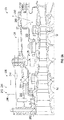
- FIG. 1 schematically illustrates a gas turbine engine 20.
- the gas turbine engine 20 is disclosed herein as a two-spool turbofan that generally incorporates a fan section 22, a compressor section 24, a combustor section 26 and a turbine section 28.
- the fan section 22 drives air along a bypass flow path B in a bypass duct, while the compressor section 24 drives air along a core flow path C for compression and communication into the combustor section 26 then expansion through the turbine section 28.
- FIG. 1 schematically illustrates a gas turbine engine 20.
- the gas turbine engine 20 is disclosed herein as a two-spool turbofan that generally incorporates a fan section 22, a compressor section 24, a combustor section 26 and a turbine section 28.
- the fan section 22 drives air along a bypass flow path B in a bypass duct
- the compressor section 24 drives air along a core flow path C for compression and communication into the combustor section 26 then expansion through the turbine section 28.
- the exemplary engine 20 generally includes a low speed spool 30 and a high speed spool 32 mounted for rotation about an engine central longitudinal axis A relative to an engine static structure 36 via several bearing systems 38. It should be understood that various bearing systems 38 at various locations may alternatively or additionally be provided, and the location of bearing systems 38 may be varied as appropriate to the application.
- the low speed spool 30 generally includes an inner shaft 40 that interconnects a fan 42, a low pressure compressor 44 and a low pressure turbine 46.
- the inner shaft 40 is connected to the fan 42 through a speed change mechanism, which in exemplary gas turbine engine 20 is illustrated as a geared architecture 48 to drive the fan 42 at a lower speed than the low speed spool 30.
- the high speed spool 32 includes an outer shaft 50 that interconnects a high pressure compressor 52 and high pressure turbine 54.
- a combustor 56 is arranged in exemplary gas turbine 20 between the high pressure compressor 52 and the high pressure turbine 54.
- An engine static structure 36 is arranged generally between the high pressure turbine 54 and the low pressure turbine 46.
- the engine static structure 36 further supports bearing systems 38 in the turbine section 28.
- the inner shaft 40 and the outer shaft 50 are concentric and rotate via bearing systems 38 about the engine central longitudinal axis "A" which is collinear with their longitudinal axes.
- each of the positions of the fan section 22, compressor section 24, combustor section 26, turbine section 28, and fan drive gear system 48 may be varied.
- gear system 48 may be located aft of combustor section 26 or even aft of turbine section 28, and fan section 22 may be positioned forward or aft of the location of gear system 48.
- the engine 20 in one example is a high-bypass geared aircraft engine.
- the engine 20 bypass ratio is greater than about six (6), with an example embodiment being greater than about ten (10)
- the geared architecture 48 is an epicyclic gear train, such as a planetary gear system or other gear system, with a gear reduction ratio of greater than about 2.3 and the low pressure turbine 46 has a pressure ratio that is greater than about five (5).
- the engine 20 bypass ratio is greater than about ten (10:1)
- the fan diameter is significantly larger than that of the low pressure compressor 44
- the low pressure turbine 46 has a pressure ratio that is greater than about five (5:1).
- Low pressure turbine 46 pressure ratio is pressure measured prior to inlet of low pressure turbine 46 as related to the pressure at the outlet of the low pressure turbine 46 prior to an exhaust nozzle.
- the geared architecture 48 may be an epicycle gear train, such as a planetary gear system or other gear system, with a gear reduction ratio of greater than about 2.3:1. It should be understood, however, that the above parameters are only exemplary of one embodiment of a geared architecture engine and that the present disclosure is applicable to other gas turbine engines including direct drive turbofans.
- the fan section 22 of the engine 20 is designed for a particular flight condition--typically cruise at about 0.8 Mach and about 35,000 feet (10,668 meters).
- 'TSFC Thrust Specific Fuel Consumption
- Low fan pressure ratio is the pressure ratio across the fan blade alone, without a Fan Exit Guide Vane (“FEGV”) system.
- the low fan pressure ratio as disclosed herein according to one non-limiting embodiment is less than about 1.45.
- Low corrected fan tip speed is the actual fan tip speed in ft/sec divided by an industry standard temperature correction of [(Tram °R)/(518.7 °R)] 0.5 .
- the "Low corrected fan tip speed” as disclosed herein according to one non-limiting embodiment is less than about 1150 ft/second (350.5 m/sec).
- FIG. 1 illustrates one example of the gas turbine engine 20
- any number of spools, inclusion or omission of the gear system 48, and/or other elements and subsystems are contemplated.
- rotor systems described herein can be used in a variety of applications and need not be limited to gas turbine engines for aircraft applications.
- rotor systems can be included in power generation systems, which may be ground-based as a fixed position or mobile system, and other such applications.
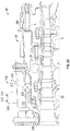
- the compressor section 24 includes a front portion 25 and an aft portion 27.
- the CCC control system 200 is configured to adjust an amount of cool, mid-stage compressor bleed air 202 (referred to herein as bleed air 202) delivered to the front portion 25 and the aft portion 27 based on an in-flight phase of the aircraft.
- the CCC control system 200 determines a transition time at which the in-flight phase transitions from a cruise phase to a descent phase, and adjusts the amount of bleed air 202 delivered prior to initiating the descent phase to adjust a clearance area of the compressor section 24.
- the CCC control system 200 can deliver bleed air 202 to both the front portion 25 and the aft portion 27 during the aircraft's' cruise phase, and can reduce the amount of bleed air 202 or completely block the bleed air 202 delivered to the aft portion 27 prior to transitioning from the cruise phase to the descent phase.
- the CCC control system 200 includes a CCC valve 204 and a CCC controller 206.
- the CCC valve 204 is disposed between the front portion 25 and the aft portion 27, and is adjustable among a plurality of different positions.
- the CCC valve 204 is constructed as a butterfly valve operable in a first position and a second position.
- the first position delivers the bleed air 202 along a first airflow path that is in fluid communication with an aft exit port 208 installed in the aft portion 27.
- the second position delivers the bleed air 202 along a second airflow path that is in fluid communication with a front exit port 210 installed in the front portion 25.
- the bleed air 202 controls the temperature realized by the surrounding areas of the compressor section (e.g., the front portion 25 and the aft portion 27). In other words, the amount of bleed air 202 delivered to the first airflow path controls the temperature of the aft portion 27.
- the first position of the CCC valve 204 delivers the bleed air 202 to both the front portion 25 and the aft portion 27 (see FIG. 2A ), while the second position delivers the bleed air 202 to the front portion 25 and blocks the bleed air 202 from reaching the aft portion 27 (see FIG. 2B ). Accordingly, when the CCC valve 204 is adjusted into the first position ( FIG. 2A ), the aft area 27 is cooled. As a result, the dimensions of the compressor section 24 are reduced (i.e., shrinks the compressor section 24) around the rotating compressor blades and the clearance between the engine case and blade tips is minimized. When, however, the CCC valve 204 is adjusted into the second position ( FIG.
- the bleed air is blocked from reaching the aft area 27.
- the temperature of the aft area 27 increases thereby increasing the dimensions of the aft portion 27 (i.e., expand the compressor section 24). In this manner, the blade tips are prevented from contacting the engine case.
- the CCC valve 204 is illustrated as being located inside the compressor, between the inner and outer cases, to redirect the air 202 before it reaches exit ports 208 or 210.
- the location of the CCC valve 204 is not limited thereto.
- the CCC valve 204 can be located outside the compressor, with ducts from the exit ports 208 and 210 being connected to the valve 204. In this manner, the CCC valve 204 can actively block or reduce airflow through the duct of a respective connecting port 208 or 210 so as to control the clearance of the compressor section 24 as described herein.
- the CCC controller 206 is in signal communication with the CCC valve 204.
- the CCC controller 206 is configured to select a position of the CCC valve 204 based on the in-flight phase 212 of the aircraft (e.g., cruise, climb, pre-descent, etc.)
- the in-flight phase 212 can be determined according to a predetermined flight log, which is typically loaded into the flight control system and can be obtained by the CCC controller 206.
- the in-flight phase 212 can also be manually selected by an operator of the aircraft.
- a control signal indicative of the selected in-flight phase 212 can be delivered to the CCC controller 206.
- the controller 206 is made aware of the time at which the aircraft will transition between different in-flight phases, e.g., when the aircraft will transition from a cruise phase to a descent phase. Accordingly, the CCC controller 206 monitors the in-flight phase 212 of the aircraft to determine when a current in-flight will end (e.g., a cruise phase) and when the next in-flight phase (e.g., a descent phase) will begin.
- a current in-flight e.g., a cruise phase
- the next in-flight phase e.g., a descent phase
- the CCC controller 206 can selectively activate or deactivate the cooling mode by monitoring the phase transition time.
- the CCC controller 206 invokes of the CCC cooling mode and maintains the CCC valve into the first position. Accordingly, the bleed air 202 is permitted to flow through both the front portion 25 and the aft portion 27 before exiting the compressor section 24 via the aft exit port 208 (see FIG. 2A ).
- the CCC controller 206 deactivates the cooling mode and adjusts the CCC valve 204 into the second position to reduce or fully block the amount of bleed air 202 delivered to the aft portion 27 (see FIG. 2B ).
- the temperature of the aft portion 27 is increased so as to increase the dimensions of the compressor section 24. In this manner, the blade tips are prevented from contacting the engine case.
- the CCC control system 200 can also selectively activate or deactivate the cooling mode to prevent the aircraft's step-climb phase from causing the CCC bleed air pressure to fall below a pressure requirement set for customer bleed usage.
- a portion of the bleed air can be diverted to an environmental control system (ECS) (not shown).
- ECS environmental control system
- the bleed air can then further be divided into low-pressure bleed air and high-pressure bleed air.
- the ECS utilizes the bleed air (e.g., high-pressure bleed air and low-pressure bleed air) to control temperatures of various areas of the aircraft such as the cabin, flight decks, cargo compartments and avionics.
- the ECS typically aims to utilize the high-pressure bleed air and the low-pressure bleed air at particular times of flight in order to ensure air pressure requirements are satisfied.
- the aircraft's step-climb scheme can cause the air pressure to fall below the minimum pressure limit for customer air bleed, which would otherwise force an undesirable switch to the high pressure (compressor exit) customer bleed source.
- the CCC control system 200 can adjust the amount of bleed air 202 delivered through the front portion 25 and the aft portion 27 based on the in-flight phase 212 of an aircraft (e.g., the step-climb scheme) and/or a comparison of a pressure value 214 of the bleed air and a bleed air pressure threshold.
- the CCC controller 206 can obtain the step-climb scheme for the current flight log and determine pressure changes 214 the aircraft and/or bleed air are expected to realize during the flight.
- a step-climb scheme for a given flight may include a series of altitude gains (sometimes referred to as climbs) in order to achieve an optimal flight altitude for improving fuel economy.
- a given step-climb scheme typically presets or schedules the altitude gains for a given flight pattern. Therefore, the CCC controller 206 can predict the changes in altitude and pressures 214 and/or can calculate the changes in pressure expected over the course of a flight. Although not illustrated, the CCC controller 206 is in signal communication with various sensors and/or diagnostic systems to obtain various pressure measurements 214 (external air pressure, internal ambient pressures, etc.). The CCC controller 206 can compare the determined pressures to one or more pressure thresholds (e.g., the ECS minimum pressure threshold) to determine when to deactivate the CCC cooling mode. Accordingly, the CCC controller 206 can deactivate the cooling mode prior to invoking a scheduled altitude gain in order to ensure minimum bleed air pressure requirements are satisfied.
- the ECS minimum pressure threshold e.g., the ECS minimum pressure threshold
- a method of controlling compressor case clearance in a gas turbine engine begins at operation 300 and at operation 302 the cruise phase of an aircraft is detected.
- the cooling mode of the CCC control system is activated.
- the CCC valve is adjusted into a first position at operation 306 so that bleed air is delivered to both the front portion and the aft portion of the compressor section. Accordingly, cool air is delivered into the aft portion, which in turn reduces the dimensions of the engine case (i.e., shrinks the engine case) around the rotating compressor blades and minimizes the clearance between the case and blade tips.
- the CCC control system monitors the in-flight phase of the aircraft to determine whether a descent transition time is reached. When the descent transition time has not yet been reached, the CCC control system continues monitoring the in-flight phase at operation 308.
- the CCC cooling mode is deactivated at operation 310.
- the CCC valve is adjusted into a second position to reduce the amount of bleed air delivered to the aft portion of the compressor section. Accordingly, the temperature of the aft portion is increased which in turn increases the dimensions of the engine case (i.e., expand the engine case). In this manner, the blade tips are prevented from contacting the engine case.
- the descent phase of the aircraft is initiated, and the method ends at operation 316. While the above description has described the flow process of FIG. 3 in a particular order, it should be appreciated that unless otherwise specifically required in the attached claims that the ordering of the steps may be varied.
- FIG. 4 a method of controlling compressor case clearance in a gas turbine engine is illustrated according to another non-limiting embodiment.
- the method begins at operation 400 and at operation 402 the cruise phase of an aircraft is detected.
- the cooling mode of the CCC control system is activated.
- the CCC valve is adjusted into a first position at operation 406 so that bleed air is delivered to both the front portion and the aft portion of the compressor section. Accordingly, cool air is delivered into the aft portion, which in turn reduces the dimensions of the engine case (i.e., shrinks the engine case) around the rotating compressor blades and minimizes the clearance between the case and blade tips.
- the step-climb scheme for the current flight is obtained, and the expected pressures according to the scheduled altitude gains are determined at operation 410.
- the expected pressure corresponding to the next altitude gain is compared to a minimum pressure threshold (e.g., a minimum bleed air threshold requirement).
- a minimum pressure threshold e.g., a minimum bleed air threshold requirement.
- the scheduled altitude gain is initiated at operation 414.
- the method ends at operation 418.
- the method returns to operation 412 and the expected pressure corresponding to the next altitude gain is compared to a minimum pressure threshold (e.g., a minimum bleed air threshold requirement).
- the CCC cooling mode is deactivated at operation 420.
- the CCC valve is adjusted into a second position to reduce the amount of bleed air delivered to the aft portion of the compressor section. Accordingly, the temperature of the aft portion is increased so as to increase the dimensions of the engine case (i.e., expand the engine case).
- the scheduled altitude gain is initiated at operation 414.
- a determination is made as to whether the final altitude gain included in the step-climb scheme has been reached. When the final altitude gain has been reached, the method ends at operation 418.
- the method returns to operation 412 and the expected pressure corresponding to the next altitude gain is compared to a minimum pressure threshold (e.g., a minimum bleed air threshold requirement).
- a minimum pressure threshold e.g., a minimum bleed air threshold requirement
Description
- The subject matter disclosed herein generally relates to aircraft propulsion systems, and more particularly, to gas turbine engines.
- Gas turbine engines include rotors that rotate within an engine case. The rotor blade tip clearances have a significant influence on engine performance. Leakage past the blade tips can be minimized by maintaining a desired or predetermined clearance between the blade tips and the case. Clearance can be selectively increased during specific portions of the flight to avoid contact between blade tips and the case. Accordingly, thrust specific fuel consumption of the engine is thereby reduced and engine durability can be increased.
-
EP 3 216 987 discloses a system for controlling the clearance between turbine blades and a shroud which directs cooling air to the shroud causing it to contract relative to the hot shroud and thereby reduce the clearance. The cooling air is directed to the shroud during build operational modes during a flight.GB 2 169 962 - A compressor case clearance (CCC) control system is provided according to claim 1.
- A method is provided according to claim 6 to control compressor case clearance in a gas turbine engine.
- The following descriptions should not be considered limiting in any way. With reference to the accompanying drawings, like elements are numbered alike:
-
FIG. 1 is a partial cross-sectional illustration of a gas turbine engine, in accordance with an embodiment of the disclosure; -
FIG. 2A illustrates a compressor case clearance control system operating in a first mode according to a non-limiting embodiment; -
FIG. 2B illustrates the compressor case clearance control system operating in a second mode according to a non-limiting embodiment; -
FIG. 3 is a flow diagram illustrating a method of controlling compressor case clearance in a gas turbine engine; -
FIG. 4 is a flow diagram illustrating a method of controlling compressor case clearance in a gas turbine engine. - A detailed description of one or more embodiments of the disclosed apparatus and method are presented herein by way of exemplification and not limitation with reference to the Figures.
- Compressor case clearance (CCC) control systems are employed in gas turbine engines to control throttle blade clearances. These compressor case clearance control systems can actively control the clearance between the case and blade tips. Known CCC control systems, however, do not determine optimal times at which to begin adjusting the clearance dimensions of the engine case. As a result, the efficiency of thrust specific fuel consumption is not maximized.
- Various non-limiting embodiments described herein provide a CCC control system that selectively delivers cool, mid-stage compressor bleed air over the aft case based on the current in-flight phase such as, for example, cruise, climb, pre-descent, etc. By controlling the delivery of the bleed air, the temperature of the engine case can be actively varied, thereby actively controlling the clearance dimensions (e.g., shrinking or expanding) of the engine case.
- According to at least one non-limiting embodiment, a CCC control system selectively activates and deactivates a CCC cooling mode to adjust delivery of cool bleed air through the compression section of a gas turbine engine. The CCC control system includes a controller that deactivates the CCC cooling mode near the end of a cruise phase and prior to a decent or a climb. By doing so the CCC control system can prevent the aircraft's step-climb phase from causing the CCC exit air pressure to fall below the pressure limit for customer bleed, which would otherwise force a switch to the high pressure (compressor exit) customer bleed source. The deactivation of the CCC cooling mode near the end of a cruise phase may also avoid performance penalties that would otherwise occur by prematurely switching to high pressure bleed. In addition, deactivating the CCC cooling mode before starting descent can avoid the risk of rubbing out the compressor (i.e., contacting the rotor blades with the engine case) at the top of descent clearance pinch point. In the manner, the stability and integrity of the compressor hardware can be improved.
-
FIG. 1 schematically illustrates agas turbine engine 20. Thegas turbine engine 20 is disclosed herein as a two-spool turbofan that generally incorporates afan section 22, acompressor section 24, acombustor section 26 and aturbine section 28. Thefan section 22 drives air along a bypass flow path B in a bypass duct, while thecompressor section 24 drives air along a core flow path C for compression and communication into thecombustor section 26 then expansion through theturbine section 28. Although depicted as a two-spool turbofan gas turbine engine in the disclosed non-limiting embodiment, it should be understood that the concepts described herein are not limited to use with two-spool turbofans as the teachings may be applied to other types of turbine engines including three-spool architectures. - The
exemplary engine 20 generally includes alow speed spool 30 and ahigh speed spool 32 mounted for rotation about an engine central longitudinal axis A relative to an enginestatic structure 36 viaseveral bearing systems 38. It should be understood thatvarious bearing systems 38 at various locations may alternatively or additionally be provided, and the location ofbearing systems 38 may be varied as appropriate to the application. - The
low speed spool 30 generally includes aninner shaft 40 that interconnects afan 42, alow pressure compressor 44 and alow pressure turbine 46. Theinner shaft 40 is connected to thefan 42 through a speed change mechanism, which in exemplarygas turbine engine 20 is illustrated as a gearedarchitecture 48 to drive thefan 42 at a lower speed than thelow speed spool 30. Thehigh speed spool 32 includes anouter shaft 50 that interconnects ahigh pressure compressor 52 andhigh pressure turbine 54. Acombustor 56 is arranged inexemplary gas turbine 20 between thehigh pressure compressor 52 and thehigh pressure turbine 54. An enginestatic structure 36 is arranged generally between thehigh pressure turbine 54 and thelow pressure turbine 46. The enginestatic structure 36 further supports bearingsystems 38 in theturbine section 28. Theinner shaft 40 and theouter shaft 50 are concentric and rotate viabearing systems 38 about the engine central longitudinal axis "A" which is collinear with their longitudinal axes. - The core airflow is compressed by the
low pressure compressor 44 then thehigh pressure compressor 52, mixed and burned with fuel in thecombustor 56, then expanded over thehigh pressure turbine 54 andlow pressure turbine 46. Theturbines low speed spool 30 andhigh speed spool 32 in response to the expansion. It will be appreciated that each of the positions of thefan section 22,compressor section 24,combustor section 26,turbine section 28, and fandrive gear system 48 may be varied. For example,gear system 48 may be located aft ofcombustor section 26 or even aft ofturbine section 28, andfan section 22 may be positioned forward or aft of the location ofgear system 48. - The
engine 20 in one example is a high-bypass geared aircraft engine. In a further example, theengine 20 bypass ratio is greater than about six (6), with an example embodiment being greater than about ten (10), the gearedarchitecture 48 is an epicyclic gear train, such as a planetary gear system or other gear system, with a gear reduction ratio of greater than about 2.3 and thelow pressure turbine 46 has a pressure ratio that is greater than about five (5). In one disclosed embodiment, theengine 20 bypass ratio is greater than about ten (10:1), the fan diameter is significantly larger than that of thelow pressure compressor 44, and thelow pressure turbine 46 has a pressure ratio that is greater than about five (5:1).Low pressure turbine 46 pressure ratio is pressure measured prior to inlet oflow pressure turbine 46 as related to the pressure at the outlet of thelow pressure turbine 46 prior to an exhaust nozzle. The gearedarchitecture 48 may be an epicycle gear train, such as a planetary gear system or other gear system, with a gear reduction ratio of greater than about 2.3:1. It should be understood, however, that the above parameters are only exemplary of one embodiment of a geared architecture engine and that the present disclosure is applicable to other gas turbine engines including direct drive turbofans. - A significant amount of thrust is provided by the bypass flow B due to the high bypass ratio. The
fan section 22 of theengine 20 is designed for a particular flight condition--typically cruise at about 0.8 Mach and about 35,000 feet (10,668 meters). The flight condition of 0.8 Mach and 35,000 ft (10,668 meters), with the engine at its best fuel consumption--also known as "bucket cruise Thrust Specific Fuel Consumption ('TSFC)"--is the industry standard parameter of lbm of fuel being burned divided by lbf of thrust the engine produces at that minimum point. "Low fan pressure ratio" is the pressure ratio across the fan blade alone, without a Fan Exit Guide Vane ("FEGV") system. The low fan pressure ratio as disclosed herein according to one non-limiting embodiment is less than about 1.45. "Low corrected fan tip speed" is the actual fan tip speed in ft/sec divided by an industry standard temperature correction of [(Tram °R)/(518.7 °R)]0.5. The "Low corrected fan tip speed" as disclosed herein according to one non-limiting embodiment is less than about 1150 ft/second (350.5 m/sec). - While the example of
FIG. 1 illustrates one example of thegas turbine engine 20, it will be understood that any number of spools, inclusion or omission of thegear system 48, and/or other elements and subsystems are contemplated. Further, rotor systems described herein can be used in a variety of applications and need not be limited to gas turbine engines for aircraft applications. For example, rotor systems can be included in power generation systems, which may be ground-based as a fixed position or mobile system, and other such applications. - Turning now to
FIGS. 2A and2B , aCCC control system 200 is illustrated according to a non-limiting embodiment. Thecompressor section 24 includes afront portion 25 and anaft portion 27. TheCCC control system 200 is configured to adjust an amount of cool, mid-stage compressor bleed air 202 (referred to herein as bleed air 202) delivered to thefront portion 25 and theaft portion 27 based on an in-flight phase of the aircraft. In at least one embodiment, theCCC control system 200 determines a transition time at which the in-flight phase transitions from a cruise phase to a descent phase, and adjusts the amount ofbleed air 202 delivered prior to initiating the descent phase to adjust a clearance area of thecompressor section 24. For example, theCCC control system 200 can deliver bleedair 202 to both thefront portion 25 and theaft portion 27 during the aircraft's' cruise phase, and can reduce the amount ofbleed air 202 or completely block thebleed air 202 delivered to theaft portion 27 prior to transitioning from the cruise phase to the descent phase. - The
CCC control system 200 includes aCCC valve 204 and aCCC controller 206. TheCCC valve 204 is disposed between thefront portion 25 and theaft portion 27, and is adjustable among a plurality of different positions. In at least one embodiment, theCCC valve 204 is constructed as a butterfly valve operable in a first position and a second position. The first position delivers thebleed air 202 along a first airflow path that is in fluid communication with anaft exit port 208 installed in theaft portion 27. The second position delivers thebleed air 202 along a second airflow path that is in fluid communication with afront exit port 210 installed in thefront portion 25. Thebleed air 202 controls the temperature realized by the surrounding areas of the compressor section (e.g., thefront portion 25 and the aft portion 27). In other words, the amount ofbleed air 202 delivered to the first airflow path controls the temperature of theaft portion 27. - In at least one embodiment, the first position of the
CCC valve 204 delivers thebleed air 202 to both thefront portion 25 and the aft portion 27 (seeFIG. 2A ), while the second position delivers thebleed air 202 to thefront portion 25 and blocks thebleed air 202 from reaching the aft portion 27 (seeFIG. 2B ). Accordingly, when theCCC valve 204 is adjusted into the first position (FIG. 2A ), theaft area 27 is cooled. As a result, the dimensions of thecompressor section 24 are reduced (i.e., shrinks the compressor section 24) around the rotating compressor blades and the clearance between the engine case and blade tips is minimized. When, however, theCCC valve 204 is adjusted into the second position (FIG. 2B ), the bleed air is blocked from reaching theaft area 27. As a result, the temperature of theaft area 27 increases thereby increasing the dimensions of the aft portion 27 (i.e., expand the compressor section 24). In this manner, the blade tips are prevented from contacting the engine case. - In the example described above, the
CCC valve 204 is illustrated as being located inside the compressor, between the inner and outer cases, to redirect theair 202 before it reachesexit ports CCC valve 204, however, is not limited thereto. In another non-limiting embodiment, theCCC valve 204 can be located outside the compressor, with ducts from theexit ports valve 204. In this manner, theCCC valve 204 can actively block or reduce airflow through the duct of a respective connectingport compressor section 24 as described herein. - The
CCC controller 206 is in signal communication with theCCC valve 204. TheCCC controller 206 is configured to select a position of theCCC valve 204 based on the in-flight phase 212 of the aircraft (e.g., cruise, climb, pre-descent, etc.) The in-flight phase 212 can be determined according to a predetermined flight log, which is typically loaded into the flight control system and can be obtained by theCCC controller 206. The in-flight phase 212 can also be manually selected by an operator of the aircraft. In response to selecting the in-flight phase, a control signal indicative of the selected in-flight phase 212 can be delivered to theCCC controller 206. In either case, thecontroller 206 is made aware of the time at which the aircraft will transition between different in-flight phases, e.g., when the aircraft will transition from a cruise phase to a descent phase. Accordingly, theCCC controller 206 monitors the in-flight phase 212 of the aircraft to determine when a current in-flight will end (e.g., a cruise phase) and when the next in-flight phase (e.g., a descent phase) will begin. - The
CCC controller 206 can selectively activate or deactivate the cooling mode by monitoring the phase transition time. When the descent transition time has not yet been reached, for example, theCCC controller 206 invokes of the CCC cooling mode and maintains the CCC valve into the first position. Accordingly, thebleed air 202 is permitted to flow through both thefront portion 25 and theaft portion 27 before exiting thecompressor section 24 via the aft exit port 208 (seeFIG. 2A ). When, however, the descent transition time is reached, theCCC controller 206 deactivates the cooling mode and adjusts theCCC valve 204 into the second position to reduce or fully block the amount ofbleed air 202 delivered to the aft portion 27 (seeFIG. 2B ). As a result, the temperature of theaft portion 27 is increased so as to increase the dimensions of thecompressor section 24. In this manner, the blade tips are prevented from contacting the engine case. - The
CCC control system 200 can also selectively activate or deactivate the cooling mode to prevent the aircraft's step-climb phase from causing the CCC bleed air pressure to fall below a pressure requirement set for customer bleed usage. For example, a portion of the bleed air can be diverted to an environmental control system (ECS) (not shown). The bleed air can then further be divided into low-pressure bleed air and high-pressure bleed air. In general, the ECS utilizes the bleed air (e.g., high-pressure bleed air and low-pressure bleed air) to control temperatures of various areas of the aircraft such as the cabin, flight decks, cargo compartments and avionics. - The ECS typically aims to utilize the high-pressure bleed air and the low-pressure bleed air at particular times of flight in order to ensure air pressure requirements are satisfied. However, the aircraft's step-climb scheme can cause the air pressure to fall below the minimum pressure limit for customer air bleed, which would otherwise force an undesirable switch to the high pressure (compressor exit) customer bleed source.
- In at least one embodiment, the
CCC control system 200 can adjust the amount ofbleed air 202 delivered through thefront portion 25 and theaft portion 27 based on the in-flight phase 212 of an aircraft (e.g., the step-climb scheme) and/or a comparison of apressure value 214 of the bleed air and a bleed air pressure threshold. TheCCC controller 206 can obtain the step-climb scheme for the current flight log and determinepressure changes 214 the aircraft and/or bleed air are expected to realize during the flight. For example, a step-climb scheme for a given flight may include a series of altitude gains (sometimes referred to as climbs) in order to achieve an optimal flight altitude for improving fuel economy. - A given step-climb scheme typically presets or schedules the altitude gains for a given flight pattern. Therefore, the
CCC controller 206 can predict the changes in altitude andpressures 214 and/or can calculate the changes in pressure expected over the course of a flight. Although not illustrated, theCCC controller 206 is in signal communication with various sensors and/or diagnostic systems to obtain various pressure measurements 214 (external air pressure, internal ambient pressures, etc.). TheCCC controller 206 can compare the determined pressures to one or more pressure thresholds (e.g., the ECS minimum pressure threshold) to determine when to deactivate the CCC cooling mode. Accordingly, theCCC controller 206 can deactivate the cooling mode prior to invoking a scheduled altitude gain in order to ensure minimum bleed air pressure requirements are satisfied. - Referring to
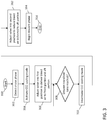
FIG. 3 , a method of controlling compressor case clearance in a gas turbine engine is illustrated according to a non-limiting embodiment. The method begins atoperation 300 and atoperation 302 the cruise phase of an aircraft is detected. Atoperation 304, the cooling mode of the CCC control system is activated. In response to activating the CCC cooling mode, the CCC valve is adjusted into a first position atoperation 306 so that bleed air is delivered to both the front portion and the aft portion of the compressor section. Accordingly, cool air is delivered into the aft portion, which in turn reduces the dimensions of the engine case (i.e., shrinks the engine case) around the rotating compressor blades and minimizes the clearance between the case and blade tips. Atoperation 308, the CCC control system monitors the in-flight phase of the aircraft to determine whether a descent transition time is reached. When the descent transition time has not yet been reached, the CCC control system continues monitoring the in-flight phase atoperation 308. - When, however, the descent transition time is reached, the CCC cooling mode is deactivated at
operation 310. Atoperation 312, the CCC valve is adjusted into a second position to reduce the amount of bleed air delivered to the aft portion of the compressor section. Accordingly, the temperature of the aft portion is increased which in turn increases the dimensions of the engine case (i.e., expand the engine case). In this manner, the blade tips are prevented from contacting the engine case. Atoperation 314, the descent phase of the aircraft is initiated, and the method ends atoperation 316. While the above description has described the flow process ofFIG. 3 in a particular order, it should be appreciated that unless otherwise specifically required in the attached claims that the ordering of the steps may be varied. - Turning to
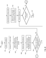
FIG. 4 , a method of controlling compressor case clearance in a gas turbine engine is illustrated according to another non-limiting embodiment. The method begins atoperation 400 and atoperation 402 the cruise phase of an aircraft is detected. Atoperation 404, the cooling mode of the CCC control system is activated. In response to activating the CCC cooling mode, the CCC valve is adjusted into a first position atoperation 406 so that bleed air is delivered to both the front portion and the aft portion of the compressor section. Accordingly, cool air is delivered into the aft portion, which in turn reduces the dimensions of the engine case (i.e., shrinks the engine case) around the rotating compressor blades and minimizes the clearance between the case and blade tips. Atoperation 408 the step-climb scheme for the current flight is obtained, and the expected pressures according to the scheduled altitude gains are determined atoperation 410. - At
operation 412, the expected pressure corresponding to the next altitude gain is compared to a minimum pressure threshold (e.g., a minimum bleed air threshold requirement). When the expected pressure is not less than the minimum pressure threshold, the scheduled altitude gain is initiated atoperation 414. At operation 416 a determination is made as to whether the final altitude gain included in the step-climb scheme has been reached. When the final altitude gain has been reached, the method ends atoperation 418. When, however, the final altitude gain has not been reached, the method returns tooperation 412 and the expected pressure corresponding to the next altitude gain is compared to a minimum pressure threshold (e.g., a minimum bleed air threshold requirement). - Turning again to
operation 412, when the expected pressure is greater than the minimum pressure threshold, the CCC cooling mode is deactivated atoperation 420. Atoperation 422, the CCC valve is adjusted into a second position to reduce the amount of bleed air delivered to the aft portion of the compressor section. Accordingly, the temperature of the aft portion is increased so as to increase the dimensions of the engine case (i.e., expand the engine case). After adjusting the amount of bleed air delivered to the aft portion, the scheduled altitude gain is initiated atoperation 414. At operation 416 a determination is made as to whether the final altitude gain included in the step-climb scheme has been reached. When the final altitude gain has been reached, the method ends atoperation 418. When, however, the final altitude gain has not been reached, the method returns tooperation 412 and the expected pressure corresponding to the next altitude gain is compared to a minimum pressure threshold (e.g., a minimum bleed air threshold requirement). While the above description has described the flow process ofFIG. 4 in a particular order, it should be appreciated that unless otherwise specifically required in the attached claims that the ordering of the steps may be varied. - The term "about" is intended to include the degree of error associated with measurement of the particular quantity based upon the equipment available at the time of filing the application.
- The terminology used herein is for the purpose of describing particular embodiments only and is not intended to be limiting of the present disclosure. As used herein, the singular forms "a", "an" and "the" are intended to include the plural forms as well, unless the context clearly indicates otherwise. It will be further understood that the terms "comprises" and/or "comprising," when used in this specification, specify the presence of stated features, integers, steps, operations, elements, and/or components, but do not preclude the presence or addition of one or more other features, integers, steps, operations, element components, and/or groups thereof.
- While the present disclosure has been described with reference to an exemplary embodiment or embodiments, it will be understood by those skilled in the art that various changes may be made and equivalents may be substituted for elements thereof without departing from the scope of the present disclosure. In addition, many modifications may be made to adapt a particular situation or material to the teachings of the present disclosure without departing from the scope thereof. Therefore, it is intended that the present disclosure not be limited to the particular embodiment disclosed as the best mode contemplated for carrying out this present disclosure, but that the present disclosure will include all embodiments falling within the scope of the claims.
Claims (14)
- An aircraft compressor case clearance (CCC) control system (200) comprising:a valve (204) that is disposed between a front portion (25) and an aft portion (27) included in a compressor section (24) of a gas turbine engine (20), the valve being adjustable among a plurality of different positions;a CCC controller (206) in signal communication with the valve, the CCC controller configured to determine an in-flight phase (212) of an aircraft operating the gas turbine engine, and to select a position of the valve among the plurality of different positions based on the in-flight phase to control delivery of bleed air (202) from the front portion to the aft portion,the valve (204) is operable in a first position to deliver the bleed air (202) to both the front portion (25) and the aft portion (27), and a second position to deliver the bleed air to the front portion while blocking the bleed air from reaching the aft portion, characterized in thatthe CCC controller (206) is configured to determine a transition time at which the in-flight phase transitions from a cruise phase to a descent phase, the CCC controller further configured to select the second position based on the transition time.
- The aircraft CCC control system (200) of claim 1, wherein the in-flight phase (212) is determined according to a predetermined flight log.
- The aircraft CCC control system (200) of claim 1 or 2, wherein the CCC controller (206) selects the position of the valve (204) among the plurality of different positions based on at least one of the in-flight phase (212) and a current pressure of the bleed air (202) at a current altitude.
- The aircraft CCC control system (200) of any of claims 1 to 3, wherein the CCC controller (206) selects the second position in response to determining that transitioning the in-flight phase (212) will reduce the current pressure of the bleed air (202) below a pressure threshold value.
- The aircraft CCC of any of claims 1 to 4, wherein the CCC controller (206) selects the second position prior to transitioning from the cruise phase to the descent phase.
- A method of controlling compressor case clearance in a gas turbine engine (20), the method comprising:disposing a valve (204) between a front portion (25) and an aft portion (27) included in a compressor section (24) of a gas turbine engine (20);determining, via a CCC controller (206), an in-flight phase (212) of an aircraft operating the gas turbine engine;selecting, via the CCC controller, a position of the valve among the plurality of different positions based on the in-flight phase, wherein the plurality of positions comprises a first position and a second position and wherein the valve is operable in the first position to deliver the bleed air to both the front portion and the aft portion, and the second position to deliver the bleed air to the front portion while blocking the bleed air from reaching the aft portion;delivering an amount of bleed air (202) from the front portion to the aft portion based on the position of the valve; andvarying a dimension of the compressor section based on the amount of delivered bleed air to control the compressor case clearance, characterized in thatselecting, via the CCC controller, a position of the valve comprises selecting the second position in response to determining a transition from a cruise in-flight phase to a descent in-flight phase.
- The method of claim 6, wherein varying the dimension of the compressor section (24) includes adjusting a temperature of the compressor section in response to the delivery of the bleed air (202).
- The method of claim 6 or 7, wherein the dimension of the compressor case clearance expands or contracts based on the temperature.
- The method of claim 6, 7, or 8, wherein selecting a position of the valve (204) further comprises:adjusting the valve into the first position among the plurality of different positions to deliver the bleed air (202) along a first airflow path that is in fluid communication with an aft exit port (208) installed in the aft portion (27); andadjusting the valve into the second position among the plurality of different positions to deliver the bleed air along a second airflow path that is in fluid communication with a front exit port (210) installed in the front portion (25).
- The method of claim 9, further comprising determining the in-flight phase (212) based on a predetermined flight log.
- The method of claim 9 or 10, further comprising selecting the position of the valve (204) among the plurality of different positions based on at least one of the in-flight phase (212) and a current pressure of the bleed air (202) at a current altitude.
- The method of any of claims 9 to 11, further comprising selecting the second position in response to determining that changing the in-flight phase (212) will reduce the current pressure of the bleed air (202) below a pressure threshold value.
- The method of any of claims 6 to 12, wherein the in-flight phase (212) is determined according to a step-climb scheme.
- The method of any of claims 6 to 13, wherein the CCC controller (206) selects the second position prior to transitioning from the cruise phase to the descent phase.
Applications Claiming Priority (1)
| Application Number | Priority Date | Filing Date | Title |
|---|---|---|---|
| US16/165,235 US10927696B2 (en) | 2018-10-19 | 2018-10-19 | Compressor case clearance control logic |
Publications (2)
| Publication Number | Publication Date |
|---|---|
| EP3640436A1 EP3640436A1 (en) | 2020-04-22 |
| EP3640436B1 true EP3640436B1 (en) | 2021-07-21 |
Family
ID=68296319
Family Applications (1)
| Application Number | Title | Priority Date | Filing Date |
|---|---|---|---|
| EP19204443.6A Active EP3640436B1 (en) | 2018-10-19 | 2019-10-21 | Compressor case clearance control logic |
Country Status (2)
| Country | Link |
|---|---|
| US (1) | US10927696B2 (en) |
| EP (1) | EP3640436B1 (en) |
Family Cites Families (18)
| Publication number | Priority date | Publication date | Assignee | Title |
|---|---|---|---|---|
| US4363599A (en) | 1979-10-31 | 1982-12-14 | General Electric Company | Clearance control |
| US4648241A (en) | 1983-11-03 | 1987-03-10 | United Technologies Corporation | Active clearance control |
| US4576547A (en) | 1983-11-03 | 1986-03-18 | United Technologies Corporation | Active clearance control |
| GB2169962B (en) | 1985-01-22 | 1988-07-13 | Rolls Royce | Blade tip clearance control |
| US8126628B2 (en) * | 2007-08-03 | 2012-02-28 | General Electric Company | Aircraft gas turbine engine blade tip clearance control |
| GB201021327D0 (en) * | 2010-12-16 | 2011-01-26 | Rolls Royce Plc | Clearance control arrangement |
| US9157331B2 (en) * | 2011-12-08 | 2015-10-13 | Siemens Aktiengesellschaft | Radial active clearance control for a gas turbine engine |
| US9260974B2 (en) | 2011-12-16 | 2016-02-16 | General Electric Company | System and method for active clearance control |
| US9758252B2 (en) | 2012-08-23 | 2017-09-12 | General Electric Company | Method, system, and apparatus for reducing a turbine clearance |
| GB201315365D0 (en) * | 2013-08-29 | 2013-10-09 | Rolls Royce Plc | Rotor tip clearance |
| EP3126640A4 (en) | 2014-03-31 | 2017-04-05 | United Technologies Corporation | Active clearance control for gas turbine engine |
| US9840932B2 (en) * | 2014-10-06 | 2017-12-12 | General Electric Company | System and method for blade tip clearance control |
| GB201518641D0 (en) * | 2015-10-21 | 2015-12-02 | Rolls Royce Plc | A system and method |
| US10138752B2 (en) | 2016-02-25 | 2018-11-27 | General Electric Company | Active HPC clearance control |
| US10393149B2 (en) * | 2016-03-11 | 2019-08-27 | General Electric Company | Method and apparatus for active clearance control |
| US10415421B2 (en) * | 2017-02-06 | 2019-09-17 | United Technologies Corporation | Thrust rating dependent active tip clearance control system |
| US10414507B2 (en) * | 2017-03-09 | 2019-09-17 | General Electric Company | Adaptive active clearance control logic |
| US10801359B2 (en) * | 2017-03-14 | 2020-10-13 | General Electric Company | Method and system for identifying rub events |
-
2018
- 2018-10-19 US US16/165,235 patent/US10927696B2/en active Active
-
2019
- 2019-10-21 EP EP19204443.6A patent/EP3640436B1/en active Active
Non-Patent Citations (1)
| Title |
|---|
| None * |
Also Published As
| Publication number | Publication date |
|---|---|
| US20200123923A1 (en) | 2020-04-23 |
| US10927696B2 (en) | 2021-02-23 |
| EP3640436A1 (en) | 2020-04-22 |
Similar Documents
| Publication | Publication Date | Title |
|---|---|---|
| US10421551B2 (en) | Aircraft anti-icing system | |
| EP2900957B1 (en) | Nacelle anti-ice valve utilized as compressor stability bleed valve during starting | |
| EP3406884B1 (en) | Bleed flow safety system | |
| EP3358144B1 (en) | Thrust rating dependent active tip clearance control system | |
| US9932905B2 (en) | Bypass duct heat exchanger with controlled fan | |
| US9957832B2 (en) | Variable area turbine | |
| EP3406883B1 (en) | Actively-driven bleed source switching | |
| EP3584427B1 (en) | Intercooled cooling air with low temperature bearing compartment air | |
| EP3594474B1 (en) | Gas turbine engine with active variable turbine cooling | |
| EP3115298B1 (en) | Nacelle anti-ice system and method with equalized flow | |
| EP3406882B1 (en) | Active bleed flow modulation | |
| US20160237844A1 (en) | Variable vane systems | |
| EP3470656B1 (en) | Modulated combustor bypass | |
| EP3640436B1 (en) | Compressor case clearance control logic | |
| EP3056668B1 (en) | High pressure compressor rotor thermal conditioning using cooled conditioned air | |
| EP3670875B1 (en) | Gas turbine engine system wear reduction | |
| US11060463B2 (en) | Modulated combustor bypass and combustor bypass valve | |
| US11976589B2 (en) | Gas turbine engine system wear reduction | |
| EP3611358B1 (en) | Bleed valve actuation system | |
| EP3617460B1 (en) | Dual valve system with different valve disc geometries | |
| EP3647563B1 (en) | Gas turbine engine control based on characteristic of cooled air |
Legal Events
| Date | Code | Title | Description |
|---|---|---|---|
| PUAI | Public reference made under article 153(3) epc to a published international application that has entered the european phase |
Free format text: ORIGINAL CODE: 0009012 |
|
| STAA | Information on the status of an ep patent application or granted ep patent |
Free format text: STATUS: THE APPLICATION HAS BEEN PUBLISHED |
|
| AK | Designated contracting states |
Kind code of ref document: A1 Designated state(s): AL AT BE BG CH CY CZ DE DK EE ES FI FR GB GR HR HU IE IS IT LI LT LU LV MC MK MT NL NO PL PT RO RS SE SI SK SM TR |
|
| AX | Request for extension of the european patent |
Extension state: BA ME |
|
| STAA | Information on the status of an ep patent application or granted ep patent |
Free format text: STATUS: REQUEST FOR EXAMINATION WAS MADE |
|
| 17P | Request for examination filed |
Effective date: 20201022 |
|
| RBV | Designated contracting states (corrected) |
Designated state(s): AL AT BE BG CH CY CZ DE DK EE ES FI FR GB GR HR HU IE IS IT LI LT LU LV MC MK MT NL NO PL PT RO RS SE SI SK SM TR |
|
| RIC1 | Information provided on ipc code assigned before grant |
Ipc: F02C 6/08 20060101ALI20201111BHEP Ipc: F01D 11/24 20060101AFI20201111BHEP |
|
| GRAP | Despatch of communication of intention to grant a patent |
Free format text: ORIGINAL CODE: EPIDOSNIGR1 |
|
| STAA | Information on the status of an ep patent application or granted ep patent |
Free format text: STATUS: GRANT OF PATENT IS INTENDED |
|
| RIN1 | Information on inventor provided before grant (corrected) |
Inventor name: ECKETT, CHRISTOPHER A. Inventor name: ACKERMANN, WILLIAM K. |
|
| INTG | Intention to grant announced |
Effective date: 20210211 |
|
| RAP1 | Party data changed (applicant data changed or rights of an application transferred) |
Owner name: RAYTHEON TECHNOLOGIES CORPORATION |
|
| GRAS | Grant fee paid |
Free format text: ORIGINAL CODE: EPIDOSNIGR3 |
|
| GRAA | (expected) grant |
Free format text: ORIGINAL CODE: 0009210 |
|
| STAA | Information on the status of an ep patent application or granted ep patent |
Free format text: STATUS: THE PATENT HAS BEEN GRANTED |
|
| AK | Designated contracting states |
Kind code of ref document: B1 Designated state(s): AL AT BE BG CH CY CZ DE DK EE ES FI FR GB GR HR HU IE IS IT LI LT LU LV MC MK MT NL NO PL PT RO RS SE SI SK SM TR |
|
| REG | Reference to a national code |
Ref country code: GB Ref legal event code: FG4D |
|
| REG | Reference to a national code |
Ref country code: CH Ref legal event code: EP |
|
| REG | Reference to a national code |
Ref country code: DE Ref legal event code: R096 Ref document number: 602019006255 Country of ref document: DE |
|
| REG | Reference to a national code |
Ref country code: AT Ref legal event code: REF Ref document number: 1412786 Country of ref document: AT Kind code of ref document: T Effective date: 20210815 |
|
| REG | Reference to a national code |
Ref country code: IE Ref legal event code: FG4D |
|
| REG | Reference to a national code |
Ref country code: LT Ref legal event code: MG9D |
|
| REG | Reference to a national code |
Ref country code: NL Ref legal event code: MP Effective date: 20210721 |
|
| REG | Reference to a national code |
Ref country code: AT Ref legal event code: MK05 Ref document number: 1412786 Country of ref document: AT Kind code of ref document: T Effective date: 20210721 |
|
| PG25 | Lapsed in a contracting state [announced via postgrant information from national office to epo] |
Ref country code: SE Free format text: LAPSE BECAUSE OF FAILURE TO SUBMIT A TRANSLATION OF THE DESCRIPTION OR TO PAY THE FEE WITHIN THE PRESCRIBED TIME-LIMIT Effective date: 20210721 Ref country code: RS Free format text: LAPSE BECAUSE OF FAILURE TO SUBMIT A TRANSLATION OF THE DESCRIPTION OR TO PAY THE FEE WITHIN THE PRESCRIBED TIME-LIMIT Effective date: 20210721 Ref country code: ES Free format text: LAPSE BECAUSE OF FAILURE TO SUBMIT A TRANSLATION OF THE DESCRIPTION OR TO PAY THE FEE WITHIN THE PRESCRIBED TIME-LIMIT Effective date: 20210721 Ref country code: LT Free format text: LAPSE BECAUSE OF FAILURE TO SUBMIT A TRANSLATION OF THE DESCRIPTION OR TO PAY THE FEE WITHIN THE PRESCRIBED TIME-LIMIT Effective date: 20210721 Ref country code: BG Free format text: LAPSE BECAUSE OF FAILURE TO SUBMIT A TRANSLATION OF THE DESCRIPTION OR TO PAY THE FEE WITHIN THE PRESCRIBED TIME-LIMIT Effective date: 20211021 Ref country code: AT Free format text: LAPSE BECAUSE OF FAILURE TO SUBMIT A TRANSLATION OF THE DESCRIPTION OR TO PAY THE FEE WITHIN THE PRESCRIBED TIME-LIMIT Effective date: 20210721 Ref country code: FI Free format text: LAPSE BECAUSE OF FAILURE TO SUBMIT A TRANSLATION OF THE DESCRIPTION OR TO PAY THE FEE WITHIN THE PRESCRIBED TIME-LIMIT Effective date: 20210721 Ref country code: HR Free format text: LAPSE BECAUSE OF FAILURE TO SUBMIT A TRANSLATION OF THE DESCRIPTION OR TO PAY THE FEE WITHIN THE PRESCRIBED TIME-LIMIT Effective date: 20210721 Ref country code: PT Free format text: LAPSE BECAUSE OF FAILURE TO SUBMIT A TRANSLATION OF THE DESCRIPTION OR TO PAY THE FEE WITHIN THE PRESCRIBED TIME-LIMIT Effective date: 20211122 Ref country code: NO Free format text: LAPSE BECAUSE OF FAILURE TO SUBMIT A TRANSLATION OF THE DESCRIPTION OR TO PAY THE FEE WITHIN THE PRESCRIBED TIME-LIMIT Effective date: 20211021 Ref country code: NL Free format text: LAPSE BECAUSE OF FAILURE TO SUBMIT A TRANSLATION OF THE DESCRIPTION OR TO PAY THE FEE WITHIN THE PRESCRIBED TIME-LIMIT Effective date: 20210721 |
|
| PG25 | Lapsed in a contracting state [announced via postgrant information from national office to epo] |
Ref country code: PL Free format text: LAPSE BECAUSE OF FAILURE TO SUBMIT A TRANSLATION OF THE DESCRIPTION OR TO PAY THE FEE WITHIN THE PRESCRIBED TIME-LIMIT Effective date: 20210721 Ref country code: LV Free format text: LAPSE BECAUSE OF FAILURE TO SUBMIT A TRANSLATION OF THE DESCRIPTION OR TO PAY THE FEE WITHIN THE PRESCRIBED TIME-LIMIT Effective date: 20210721 Ref country code: GR Free format text: LAPSE BECAUSE OF FAILURE TO SUBMIT A TRANSLATION OF THE DESCRIPTION OR TO PAY THE FEE WITHIN THE PRESCRIBED TIME-LIMIT Effective date: 20211022 |
|
| REG | Reference to a national code |
Ref country code: DE Ref legal event code: R097 Ref document number: 602019006255 Country of ref document: DE |
|
| PG25 | Lapsed in a contracting state [announced via postgrant information from national office to epo] |
Ref country code: DK Free format text: LAPSE BECAUSE OF FAILURE TO SUBMIT A TRANSLATION OF THE DESCRIPTION OR TO PAY THE FEE WITHIN THE PRESCRIBED TIME-LIMIT Effective date: 20210721 |
|
| PLBE | No opposition filed within time limit |
Free format text: ORIGINAL CODE: 0009261 |
|
| STAA | Information on the status of an ep patent application or granted ep patent |
Free format text: STATUS: NO OPPOSITION FILED WITHIN TIME LIMIT |
|
| PG25 | Lapsed in a contracting state [announced via postgrant information from national office to epo] |
Ref country code: SM Free format text: LAPSE BECAUSE OF FAILURE TO SUBMIT A TRANSLATION OF THE DESCRIPTION OR TO PAY THE FEE WITHIN THE PRESCRIBED TIME-LIMIT Effective date: 20210721 Ref country code: SK Free format text: LAPSE BECAUSE OF FAILURE TO SUBMIT A TRANSLATION OF THE DESCRIPTION OR TO PAY THE FEE WITHIN THE PRESCRIBED TIME-LIMIT Effective date: 20210721 Ref country code: RO Free format text: LAPSE BECAUSE OF FAILURE TO SUBMIT A TRANSLATION OF THE DESCRIPTION OR TO PAY THE FEE WITHIN THE PRESCRIBED TIME-LIMIT Effective date: 20210721 Ref country code: EE Free format text: LAPSE BECAUSE OF FAILURE TO SUBMIT A TRANSLATION OF THE DESCRIPTION OR TO PAY THE FEE WITHIN THE PRESCRIBED TIME-LIMIT Effective date: 20210721 Ref country code: CZ Free format text: LAPSE BECAUSE OF FAILURE TO SUBMIT A TRANSLATION OF THE DESCRIPTION OR TO PAY THE FEE WITHIN THE PRESCRIBED TIME-LIMIT Effective date: 20210721 Ref country code: AL Free format text: LAPSE BECAUSE OF FAILURE TO SUBMIT A TRANSLATION OF THE DESCRIPTION OR TO PAY THE FEE WITHIN THE PRESCRIBED TIME-LIMIT Effective date: 20210721 |
|
| REG | Reference to a national code |
Ref country code: BE Ref legal event code: MM Effective date: 20211031 |
|
| 26N | No opposition filed |
Effective date: 20220422 |
|
| PG25 | Lapsed in a contracting state [announced via postgrant information from national office to epo] |
Ref country code: MC Free format text: LAPSE BECAUSE OF FAILURE TO SUBMIT A TRANSLATION OF THE DESCRIPTION OR TO PAY THE FEE WITHIN THE PRESCRIBED TIME-LIMIT Effective date: 20210721 |
|
| PG25 | Lapsed in a contracting state [announced via postgrant information from national office to epo] |
Ref country code: LU Free format text: LAPSE BECAUSE OF NON-PAYMENT OF DUE FEES Effective date: 20211021 Ref country code: IT Free format text: LAPSE BECAUSE OF FAILURE TO SUBMIT A TRANSLATION OF THE DESCRIPTION OR TO PAY THE FEE WITHIN THE PRESCRIBED TIME-LIMIT Effective date: 20210721 Ref country code: BE Free format text: LAPSE BECAUSE OF NON-PAYMENT OF DUE FEES Effective date: 20211031 |
|
| PG25 | Lapsed in a contracting state [announced via postgrant information from national office to epo] |
Ref country code: IE Free format text: LAPSE BECAUSE OF NON-PAYMENT OF DUE FEES Effective date: 20211021 |
|
| REG | Reference to a national code |
Ref country code: CH Ref legal event code: PL |
|
| P01 | Opt-out of the competence of the unified patent court (upc) registered |
Effective date: 20230521 |
|
| PG25 | Lapsed in a contracting state [announced via postgrant information from national office to epo] |
Ref country code: CY Free format text: LAPSE BECAUSE OF FAILURE TO SUBMIT A TRANSLATION OF THE DESCRIPTION OR TO PAY THE FEE WITHIN THE PRESCRIBED TIME-LIMIT Effective date: 20210721 |
|
| PG25 | Lapsed in a contracting state [announced via postgrant information from national office to epo] |
Ref country code: LI Free format text: LAPSE BECAUSE OF NON-PAYMENT OF DUE FEES Effective date: 20221031 Ref country code: HU Free format text: LAPSE BECAUSE OF FAILURE TO SUBMIT A TRANSLATION OF THE DESCRIPTION OR TO PAY THE FEE WITHIN THE PRESCRIBED TIME-LIMIT; INVALID AB INITIO Effective date: 20191021 Ref country code: CH Free format text: LAPSE BECAUSE OF NON-PAYMENT OF DUE FEES Effective date: 20221031 |
|
| PGFP | Annual fee paid to national office [announced via postgrant information from national office to epo] |
Ref country code: GB Payment date: 20230920 Year of fee payment: 5 |
|
| PGFP | Annual fee paid to national office [announced via postgrant information from national office to epo] |
Ref country code: FR Payment date: 20230920 Year of fee payment: 5 |
|
| PGFP | Annual fee paid to national office [announced via postgrant information from national office to epo] |
Ref country code: DE Payment date: 20230920 Year of fee payment: 5 |