EP3216987A1 - Compressor active clearance control system, corresponding turbomachine and method of controlling tip clearence in a compressor - Google Patents
Compressor active clearance control system, corresponding turbomachine and method of controlling tip clearence in a compressor Download PDFInfo
- Publication number
- EP3216987A1 EP3216987A1 EP17160474.7A EP17160474A EP3216987A1 EP 3216987 A1 EP3216987 A1 EP 3216987A1 EP 17160474 A EP17160474 A EP 17160474A EP 3216987 A1 EP3216987 A1 EP 3216987A1
- Authority
- EP
- European Patent Office
- Prior art keywords
- cavity
- annular casing
- compressor
- inner annular
- cooling fluid
- Prior art date
- Legal status (The legal status is an assumption and is not a legal conclusion. Google has not performed a legal analysis and makes no representation as to the accuracy of the status listed.)
- Withdrawn
Links
- 238000000034 method Methods 0.000 title claims abstract description 32
- 239000012809 cooling fluid Substances 0.000 claims abstract description 35
- 238000004891 communication Methods 0.000 claims description 12
- 230000005465 channeling Effects 0.000 claims description 8
- 239000011810 insulating material Substances 0.000 claims 1
- 238000012546 transfer Methods 0.000 description 12
- 238000012545 processing Methods 0.000 description 9
- 239000000567 combustion gas Substances 0.000 description 7
- 238000001816 cooling Methods 0.000 description 7
- 239000007789 gas Substances 0.000 description 7
- 230000003247 decreasing effect Effects 0.000 description 6
- 230000007423 decrease Effects 0.000 description 5
- 230000004044 response Effects 0.000 description 5
- 238000002485 combustion reaction Methods 0.000 description 3
- 230000006870 function Effects 0.000 description 2
- 230000002093 peripheral effect Effects 0.000 description 2
- 230000001141 propulsive effect Effects 0.000 description 2
- 230000000694 effects Effects 0.000 description 1
- 238000005516 engineering process Methods 0.000 description 1
- 239000000446 fuel Substances 0.000 description 1
- 238000002955 isolation Methods 0.000 description 1
- 230000007774 longterm Effects 0.000 description 1
- 238000005259 measurement Methods 0.000 description 1
- 230000001902 propagating effect Effects 0.000 description 1
Images

Classifications
-
- F—MECHANICAL ENGINEERING; LIGHTING; HEATING; WEAPONS; BLASTING
- F04—POSITIVE - DISPLACEMENT MACHINES FOR LIQUIDS; PUMPS FOR LIQUIDS OR ELASTIC FLUIDS
- F04D—NON-POSITIVE-DISPLACEMENT PUMPS
- F04D29/00—Details, component parts, or accessories
- F04D29/60—Mounting; Assembling; Disassembling
- F04D29/64—Mounting; Assembling; Disassembling of axial pumps
- F04D29/642—Mounting; Assembling; Disassembling of axial pumps by adjusting the clearances between rotary and stationary parts
-
- F—MECHANICAL ENGINEERING; LIGHTING; HEATING; WEAPONS; BLASTING
- F01—MACHINES OR ENGINES IN GENERAL; ENGINE PLANTS IN GENERAL; STEAM ENGINES
- F01D—NON-POSITIVE DISPLACEMENT MACHINES OR ENGINES, e.g. STEAM TURBINES
- F01D11/00—Preventing or minimising internal leakage of working-fluid, e.g. between stages
- F01D11/08—Preventing or minimising internal leakage of working-fluid, e.g. between stages for sealing space between rotor blade tips and stator
- F01D11/14—Adjusting or regulating tip-clearance, i.e. distance between rotor-blade tips and stator casing
- F01D11/20—Actively adjusting tip-clearance
- F01D11/24—Actively adjusting tip-clearance by selectively cooling-heating stator or rotor components
-
- F—MECHANICAL ENGINEERING; LIGHTING; HEATING; WEAPONS; BLASTING
- F01—MACHINES OR ENGINES IN GENERAL; ENGINE PLANTS IN GENERAL; STEAM ENGINES
- F01D—NON-POSITIVE DISPLACEMENT MACHINES OR ENGINES, e.g. STEAM TURBINES
- F01D25/00—Component parts, details, or accessories, not provided for in, or of interest apart from, other groups
- F01D25/08—Cooling; Heating; Heat-insulation
- F01D25/12—Cooling
-
- F—MECHANICAL ENGINEERING; LIGHTING; HEATING; WEAPONS; BLASTING
- F01—MACHINES OR ENGINES IN GENERAL; ENGINE PLANTS IN GENERAL; STEAM ENGINES
- F01D—NON-POSITIVE DISPLACEMENT MACHINES OR ENGINES, e.g. STEAM TURBINES
- F01D25/00—Component parts, details, or accessories, not provided for in, or of interest apart from, other groups
- F01D25/24—Casings; Casing parts, e.g. diaphragms, casing fastenings
- F01D25/26—Double casings; Measures against temperature strain in casings
-
- F—MECHANICAL ENGINEERING; LIGHTING; HEATING; WEAPONS; BLASTING
- F01—MACHINES OR ENGINES IN GENERAL; ENGINE PLANTS IN GENERAL; STEAM ENGINES
- F01D—NON-POSITIVE DISPLACEMENT MACHINES OR ENGINES, e.g. STEAM TURBINES
- F01D9/00—Stators
- F01D9/06—Fluid supply conduits to nozzles or the like
- F01D9/065—Fluid supply or removal conduits traversing the working fluid flow, e.g. for lubrication-, cooling-, or sealing fluids
-
- F—MECHANICAL ENGINEERING; LIGHTING; HEATING; WEAPONS; BLASTING
- F02—COMBUSTION ENGINES; HOT-GAS OR COMBUSTION-PRODUCT ENGINE PLANTS
- F02K—JET-PROPULSION PLANTS
- F02K3/00—Plants including a gas turbine driving a compressor or a ducted fan
- F02K3/02—Plants including a gas turbine driving a compressor or a ducted fan in which part of the working fluid by-passes the turbine and combustion chamber
- F02K3/04—Plants including a gas turbine driving a compressor or a ducted fan in which part of the working fluid by-passes the turbine and combustion chamber the plant including ducted fans, i.e. fans with high volume, low pressure outputs, for augmenting the jet thrust, e.g. of double-flow type
- F02K3/06—Plants including a gas turbine driving a compressor or a ducted fan in which part of the working fluid by-passes the turbine and combustion chamber the plant including ducted fans, i.e. fans with high volume, low pressure outputs, for augmenting the jet thrust, e.g. of double-flow type with front fan
-
- F—MECHANICAL ENGINEERING; LIGHTING; HEATING; WEAPONS; BLASTING
- F04—POSITIVE - DISPLACEMENT MACHINES FOR LIQUIDS; PUMPS FOR LIQUIDS OR ELASTIC FLUIDS
- F04D—NON-POSITIVE-DISPLACEMENT PUMPS
- F04D19/00—Axial-flow pumps
- F04D19/02—Multi-stage pumps
-
- F—MECHANICAL ENGINEERING; LIGHTING; HEATING; WEAPONS; BLASTING
- F04—POSITIVE - DISPLACEMENT MACHINES FOR LIQUIDS; PUMPS FOR LIQUIDS OR ELASTIC FLUIDS
- F04D—NON-POSITIVE-DISPLACEMENT PUMPS
- F04D29/00—Details, component parts, or accessories
- F04D29/58—Cooling; Heating; Diminishing heat transfer
- F04D29/582—Cooling; Heating; Diminishing heat transfer specially adapted for elastic fluid pumps
- F04D29/5846—Cooling; Heating; Diminishing heat transfer specially adapted for elastic fluid pumps cooling by injection
-
- F—MECHANICAL ENGINEERING; LIGHTING; HEATING; WEAPONS; BLASTING
- F04—POSITIVE - DISPLACEMENT MACHINES FOR LIQUIDS; PUMPS FOR LIQUIDS OR ELASTIC FLUIDS
- F04D—NON-POSITIVE-DISPLACEMENT PUMPS
- F04D29/00—Details, component parts, or accessories
- F04D29/58—Cooling; Heating; Diminishing heat transfer
- F04D29/582—Cooling; Heating; Diminishing heat transfer specially adapted for elastic fluid pumps
- F04D29/5853—Cooling; Heating; Diminishing heat transfer specially adapted for elastic fluid pumps heat insulation or conduction
-
- F—MECHANICAL ENGINEERING; LIGHTING; HEATING; WEAPONS; BLASTING
- F05—INDEXING SCHEMES RELATING TO ENGINES OR PUMPS IN VARIOUS SUBCLASSES OF CLASSES F01-F04
- F05D—INDEXING SCHEME FOR ASPECTS RELATING TO NON-POSITIVE-DISPLACEMENT MACHINES OR ENGINES, GAS-TURBINES OR JET-PROPULSION PLANTS
- F05D2220/00—Application
- F05D2220/30—Application in turbines
- F05D2220/32—Application in turbines in gas turbines
-
- F—MECHANICAL ENGINEERING; LIGHTING; HEATING; WEAPONS; BLASTING
- F05—INDEXING SCHEMES RELATING TO ENGINES OR PUMPS IN VARIOUS SUBCLASSES OF CLASSES F01-F04
- F05D—INDEXING SCHEME FOR ASPECTS RELATING TO NON-POSITIVE-DISPLACEMENT MACHINES OR ENGINES, GAS-TURBINES OR JET-PROPULSION PLANTS
- F05D2260/00—Function
- F05D2260/20—Heat transfer, e.g. cooling
- F05D2260/201—Heat transfer, e.g. cooling by impingement of a fluid
-
- Y—GENERAL TAGGING OF NEW TECHNOLOGICAL DEVELOPMENTS; GENERAL TAGGING OF CROSS-SECTIONAL TECHNOLOGIES SPANNING OVER SEVERAL SECTIONS OF THE IPC; TECHNICAL SUBJECTS COVERED BY FORMER USPC CROSS-REFERENCE ART COLLECTIONS [XRACs] AND DIGESTS
- Y02—TECHNOLOGIES OR APPLICATIONS FOR MITIGATION OR ADAPTATION AGAINST CLIMATE CHANGE
- Y02T—CLIMATE CHANGE MITIGATION TECHNOLOGIES RELATED TO TRANSPORTATION
- Y02T50/00—Aeronautics or air transport
- Y02T50/60—Efficient propulsion technologies, e.g. for aircraft
Definitions
- a clearance control system for a turbomachine includes a compressor defining an axis of rotation and an inner annular casing extending circumferentially over at least a portion of the compressor.
- the inner annular casing includes a radially outer surface.
- the turbomachine further includes an outer annular casing extending over at least a portion of the inner annular casing.
- the inner annular casing and the outer annular casing define a plurality of cavities therebetween.
- the clearance control system includes a manifold system including a plurality of conduits disposed within the plurality of cavities. The plurality of conduits extends axially along the inner annular casing.
- Combustion gases 166 are then routed through LP turbine 130 where a second portion of thermal and kinetic energy is extracted from combustion gases 166 via sequential stages of LP turbine stator vanes 172 that are coupled to outer casing 118 and LP turbine rotor blades 174 that are coupled to LP shaft or spool 136, thus causing LP shaft or spool 136 to rotate, thereby supporting operation of LP compressor 122 and/or rotation of fan 138.
- Distribution manifold 212 is an annular supply tube circumscribing at least a portion of HP compressor 124.
- Supply tubes 214 are coupled in flow communication with distribution manifold 212 and impingement system 206.
- Impingement system 206 includes a plurality of plenums 216 circumferentially spaced apart on a radially outer surface 218 of inner annular casing 200. Plenums 216 are in flow communication with radially outer surface 218 of inner annular casing 200.
- portion of air 165 (shown in FIG. 1 ) is directed or routed into forward cavity 302 through fourth stage inner bleed slot 322.
- Portion of air 165 is directed into fourth stage bleed conduit 153 through fourth stage outer bleed slot 326 as indicated by arrow 332.
- Portion of air 332 is directed into transfer conduit 159 as indicated by arrow 334.
- Valve 161 is open and allows portion of air 334 to continue to the aircraft for use by the aircraft.
- portion of air 167 (shown in FIG. 1 ) is directed or routed into bleed cavity 304 through seventh stage bleed slot 324.
- Portion of air 167 is directed into seventh stage bleed conduit 155 through seventh stage outer bleed slot 326 as indicated by arrow 336 and continues to the aircraft for use by the aircraft.
Landscapes
- Engineering & Computer Science (AREA)
- Mechanical Engineering (AREA)
- General Engineering & Computer Science (AREA)
- Physics & Mathematics (AREA)
- Thermal Sciences (AREA)
- Chemical & Material Sciences (AREA)
- Combustion & Propulsion (AREA)
- Fluid Mechanics (AREA)
- Turbine Rotor Nozzle Sealing (AREA)
- Structures Of Non-Positive Displacement Pumps (AREA)
Abstract
Description
- The field of the disclosure relates generally to gas turbine engines and, more particularly, to a method and apparatus for active clearance control in gas turbine engines.
- At least some known aircraft engines generate heat during operation in various internal components, such as, but, not limited to, a high pressure compressor, which includes a rotor disk, compressor blades coupled to the rotor disk, and a casing housing the highpressure compressor. Differential thermal expansion of the disk, compressor blades, and compressor casing change the clearance between the tips of the compressor blades and the inner surface of the compressor casing. Engine inefficiencies occur when the clearance between the compressor blade tips and the inner surface of the compressor casing is large, thereby facilitating decreased compressor pressure rise capability and decreased stability. Active clearance control maintains the clearance between the compressor blade tips and the inner compressor casing. At least some of the known methods for controlling the clearance between the compressor blade tips and the inner compressor casing are active thermal control and active mechanical control. For example, some known active thermal control methods use compressor bleed air and fan exhaust air to cool the inner compressor casing. Compressor bleed air and fan exhaust air are directed to the outer radial surface of the inner compressor case. The compressor bleed air and fan exhaust air cool the inner compressor casing. The active thermal control method has a slow thermal response.
- In addition, some known active mechanical control methods use linkages and actuation to control the clearance between the compressor blade tips and the inner compressor casing. Segmented shrouds attached to a unison ring and actuators individually control the positioning of each shroud. The active mechanical control method has a quick response rate, but the additional equipment required for the active mechanical control method adds weight to the aircraft.
- In one aspect, a clearance control system for a turbomachine is provided. The turbomachine includes a compressor defining an axis of rotation and an inner annular casing extending circumferentially over at least a portion of the compressor. The inner annular casing includes a radially outer surface. The turbomachine further includes an outer annular casing extending over at least a portion of the inner annular casing. The inner annular casing and the outer annular casing define a plurality of cavities therebetween. The clearance control system includes a manifold system including a plurality of conduits disposed within the plurality of cavities. The plurality of conduits extends axially along the inner annular casing. The plurality of conduits is configured to channel a flow of cooling fluid between the plurality of cavities. The clearance control system also includes an impingement system including a header and a plurality of plenums configured to channel the flow of cooling fluid to the radially outer surface of the inner annular casing and disposed within the plurality of cavities. The impingement system extends circumferentially about the inner annular casing. The plurality of conduits is configured to channel the flow of cooling fluid to the impingement system. The clearance control system further includes a channel system including a plurality of channels disposed on the radially outer surface of the outer annular casing and is configured to channel the flow of cooling fluid to the turbomachine. Wherein, the plurality of channels is configured to control the flow of cooling fluid to the manifold system.
- In another aspect, a method of controlling a clearance between a tip of a plurality of compressor blades and an inner annular casing is provided. The method includes defining a first cavity, a second cavity, and a third cavity between the inner annular casing and an outer annular casing. The method also includes channeling a plurality of flows of cooling fluid from the first cavity to a manifold system including a plurality of conduits disposed within the second and third cavities. The method further includes channeling the plurality of flows of cooling fluid from the manifold system to an impingement system disposed within the third cavity and positioned on a radially outer surface of the inner annular casing.
- In yet another aspect, a turbomachine is provided. The turbomachine includes a compressor defining an axis of rotation and an inner annular casing extending circumferentially over at least a portion of the compressor. The inner annular casing includes a radially outer surface. The turbomachine further includes an outer annular casing extending over at least a portion of the inner annular casing. The inner annular casing and the outer annular casing define a plurality of cavities therebetween. The clearance control system includes a manifold system including a plurality of conduits disposed within the plurality of cavities. The plurality of conduits extends axially along the inner annular casing. The plurality of conduits is configured to channel a flow of cooling fluid between the plurality of cavities. The clearance control system also includes an impingement system including a header and a plurality of plenums configured to channel the flow of cooling fluid to the radially outer surface of the inner annular casing and disposed within the plurality of cavities. The impingement system extends circumferentially about the inner annular casing. The plurality of conduits is configured to channel the flow of cooling fluid to the impingement system. The clearance control system further includes a channel system including a plurality of channels disposed on the radially outer surface of the outer annular casing and configured to channel the flow of cooling fluid to the turbomachine. Wherein, the plurality of channels is configured to control the flow of cooling fluid to the manifold system.
- These and other features, aspects, and advantages of the present disclosure will become better understood when the following detailed description is read with reference to the accompanying drawings in which like characters represent like parts throughout the drawings, wherein:
-
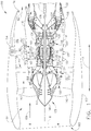
FIG. 1 is a schematic view of a gas turbine engine; -
FIG. 2 is a perspective view of the active clearance control system shown inFIG. 1 ; -
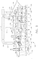
FIG. 3 is a schematic view of the active clearance control system shown inFIG. 1 and2 disposed within a cavity isolated from a high pressure compressor bleed air. - Unless otherwise indicated, the drawings provided herein are meant to illustrate features of embodiments of the disclosure. These features are believed to be applicable in a wide variety of systems comprising one or more embodiments of the disclosure. As such, the drawings are not meant to include all conventional features known by those of ordinary skill in the art to be required for the practice of the embodiments disclosed herein.
- In the following specification and the claims, reference will be made to a number of terms, which shall be defined to have the following meanings.
- The singular forms "a", "an", and "the" include plural references unless the context clearly dictates otherwise.
- "Optional" or "optionally" means that the subsequently described event or circumstance may or may not occur, and that the description includes instances where the event occurs and instances where it does not.
- Approximating language, as used herein throughout the specification and claims, may be applied to modify any quantitative representation that could permissibly vary without resulting in a change in the basic function to which it is related. Accordingly, a value modified by a term or terms, such as "about", "approximately", and "substantially", are not to be limited to the precise value specified. In at least some instances, the approximating language may correspond to the precision of an instrument for measuring the value. Here and throughout the specification and claims, range limitations may be combined and/or interchanged, such ranges are identified and include all the sub-ranges contained therein unless context or language indicates otherwise.
- As used herein, the terms "processor" and "computer", and related terms, e.g., "processing device", "computing device", and "controller" are not limited to just those integrated circuits referred to in the art as a computer, but broadly refers to a microcontroller, a microcomputer, a programmable logic controller (PLC), an application specific integrated circuit, and other programmable circuits, and these terms are used interchangeably herein. In the embodiments described herein, memory may include, but is not limited to, a computer-readable medium, such as a random access memory (RAM), and a computer-readable non-volatile medium, such as flash memory. Alternatively, a floppy disk, a compact disc - read only memory (CD-ROM), a magneto-optical disk (MOD), and/or a digital versatile disc (DVD) may also be used. Also, in the embodiments described herein, additional input channels may be, but are not limited to, computer peripherals associated with an operator interface such as a mouse and a keyboard. Alternatively, other computer peripherals may also be used that may include, for example, but not be limited to, a scanner. Furthermore, in the exemplary embodiment, additional output channels may include, but not be limited to, an operator interface monitor.
- As used herein, the term "non-transitory computer-readable media" is intended to be representative of any tangible computer-based device implemented in any method or technology for short-term and long-term storage of information, such as, computer-readable instructions, data structures, program modules and sub-modules, or other data in any device. Therefore, the methods described herein may be encoded as executable instructions embodied in a tangible, non-transitory, computer readable medium, including, without limitation, a storage device and/or a memory device. Such instructions, when executed by a processor, cause the processor to perform at least a portion of the methods described herein. Moreover, as used herein, the term "non-transitory computer-readable media" includes all tangible, computer-readable media, including, without limitation, non-transitory computer storage devices, including, without limitation, volatile and nonvolatile media, and removable and non-removable media such as a firmware, physical and virtual storage, CD-ROMs, DVDs, and any other digital source such as a network or the Internet, as well as yet to be developed digital means, with the sole exception being a transitory, propagating signal.
- Embodiments of the active clearance control system described herein control the clearance between the inner annular casing of, for example, a high pressure compressor in a turbomachine, e.g. an aircraft engine, and high pressure compressor blade tips. The active clearance control system includes an air inlet, a manifold system, a controller, and an impingement system. The air inlet directs fourth stage compressor bleed air from the bypass airflow passage to the manifold system. The manifold system directs air to the impingement system through a distribution manifold and a plurality of supply tubes. An air valve and a controller control the volume of air directed to the impingement system. The supply tubes direct air to a plurality of plenums in the impingement system. The plenums cool the inner annular casing of the high pressure compressor by directing air to the radially outer surface of the inner annular casing. Cooling the inner annular casing of the high pressure compressor reduces thermal expansion of the casing and decreases the clearance between the inner annular casing of a high pressure compressor in an aircraft engine and high pressure compressor blade tips.
- The active clearance control system described herein offers advantages over known methods of controlling clearances in aircraft engines. More specifically, the active clearance control system described herein facilitates using fourth stage compressor bleed air, rather than seventh stage compressor bleed air, as the cooling fluid on the compressor casing. Fourth stage compressor bleed air is typically substantially cooler than seventh stage compressor bleed air. Using fourth stage compressor bleed air as the cooling fluid facilitates a quicker thermal response and faster clearance control. Furthermore, the active clearance control system described herein reduces the weight of the aircraft by reducing the number and/or size of mechanical parts for controlling the clearance between the inner annular casing of a high pressure compressor in an aircraft engine and high pressure compressor blade tips. Additionally, the active clearance control system described herein reduces the weight of the aircraft by improving the performance of the engine.
-
FIG. 1 is a schematic cross-sectional view of agas turbine engine 110 in accordance with an exemplary embodiment of the present disclosure. In the exemplary embodiment,gas turbine engine 110 is a high-bypassturbofan jet engine 110, referred to herein as "turbofan engine 110." As shown inFIG. 1 ,turbofan engine 110 defines an axial direction A (extending parallel to alongitudinal centerline 112 provided for reference) and a radial direction R. In general,turbofan engine 110 includes afan section 114 and acore turbine engine 116 disposed downstream fromfan section 114. - Exemplary
core turbine engine 116 depicted generally includes a substantially tubularouter casing 118 that defines anannular inlet 120.Outer casing 118 and aninner casing 119 encases, in serial flow relationship, acompressor section 123 including a booster or low pressure (LP)compressor 122 and a high pressure (HP)compressor 124; acombustion section 126; a turbine section including a high pressure (HP)turbine 128 and a low pressure (LP)turbine 130; and a jetexhaust nozzle section 132. The volume betweenouter casing 118 andinner casing 119 forms a plurality o fcavities 121. A high pressure (HP) shaft orspool 134 drivingly connectsHP turbine 128 toHP compressor 124. A low pressure (LP) shaft orspool 136 drivingly connectsLP turbine 130 toLP compressor 122.Compressor section 123,combustion section 126, turbine section, andnozzle section 132 together define acore air flowpath 137. - As shown in
FIG. 1 ,fan section 114 includes afan 138 having a plurality offan blades 140 coupled to adisk 142 in a spaced apart manner. As depicted,fan blades 140 extend outwardly fromdisk 142 generally along radial directionR. Fan blades 140 anddisk 142, are together rotatable aboutlongitudinal axis 112 byLP shaft 136. - In the exemplary embodiment,
disk 142 is covered by rotatablefront hub 148 aerodynamically contoured to promote an airflow through plurality offan blades 140. Additionally,exemplary fan section 114 includes an annular fan casing orouter nacelle 150 that circumferentially surroundsfan 138 and/or at least a portion ofcore turbine engine 116.Nacelle 150 is configured to be supported relative tocore turbine engine 116 by a plurality of circumferentially-spaced outlet guide vanes 152. Adownstream section 154 ofnacelle 150 extends over an outer portion ofcore turbine engine 116 so as to define abypass airflow passage 156 therebetween. A plurality of activeclearance control systems 151 are disposed withincavities 121 and circumscribecore turbine engine 116. A fourthstage bleed conduit 153, a seventhstage bleed conduit 155, and a deadcavity bleed conduit 157 are disposed onouter casing 118. Atransfer conduit 159 couples fourthstage bleed conduit 153 and deadcavity bleed conduit 157 in flow communication. Avalve 161 is disposed withintransfer conduit 159 controls flows within fourthstage bleed conduit 153, deadcavity bleed conduit 157, and transferconduit 159. Acontroller 163controls valve 161. - During operation of
turbofan engine 110, a volume ofair 158 entersturbofan engine 110 through an associatedinlet 160 ofnacelle 150 and/orfan section 114. As volume ofair 158 passes acrossfan blades 140, a first portion ofair 158 as indicated byarrows 162 is directed or routed intobypass airflow passage 156 and a second portion ofair 158 as indicated byarrow 164 is directed or routed intocore air flowpath 137, or more specifically intoLP compressor 122. The ratio between first portion ofair 162 and second portion ofair 164 is commonly known as a bypass ratio. The pressure of second portion ofair 164 is then increased as it is routed throughHP compressor 124 and intocombustion section 126, where it is mixed with fuel and burned to providecombustion gases 166. - A first bleed portion of first portion of
air 164 as indicated byarrows 165 is bled fromHP compressor 124 intocavities 121 and is directed into activeclearance control system 151 to coolinner casing 119 or to fourthstage bleed conduit 153. A second bleed portion of first portion ofair 164 as indicated byarrows 167 is bled fromHP compressor 124 intocavities 121 and to seventhstage bleed conduit 155. Bleedair 165 is directed from fourthstage bleed conduit 153 intotransfer conduit 159. Closingvalve 161 reduces the flow from fourthstage bleed conduit 153 and directsmore bleed air 165 into activeclearance control system 151 to coolinner casing 119. Afterbleed air 165 coolsinner casing 119, it is directed into deadcavity bleed conduit 157. Seventhstage bleed conduit 155 and transferconduit 159direct bleed air -
Combustion gases 166 are routed throughHP turbine 128 where a portion of thermal and/or kinetic energy fromcombustion gases 166 is extracted via sequential stages of HPturbine stator vanes 168 that are coupled toouter casing 118 and HPturbine rotor blades 170 that are coupled to HP shaft orspool 134, thus causing HP shaft orspool 134 to rotate, thereby supporting operation ofHP compressor 124.Combustion gases 166 are then routed throughLP turbine 130 where a second portion of thermal and kinetic energy is extracted fromcombustion gases 166 via sequential stages of LPturbine stator vanes 172 that are coupled toouter casing 118 and LPturbine rotor blades 174 that are coupled to LP shaft orspool 136, thus causing LP shaft orspool 136 to rotate, thereby supporting operation ofLP compressor 122 and/or rotation offan 138. -
Combustion gases 166 are subsequently routed through jetexhaust nozzle section 132 ofcore turbine engine 116 to provide propulsive thrust. Simultaneously, the pressure of first portion ofair 162 is substantially increased as first portion ofair 162 is routed throughbypass airflow passage 156 before it is exhausted from a fannozzle exhaust section 176 ofturbofan engine 110, also providing propulsive thrust.HP turbine 128,LP turbine 130, and jetexhaust nozzle section 132 at least partially define a hot gas path 178 for routingcombustion gases 166 throughcore turbine engine 116. -
Exemplary turbofan engine 110 depicted inFIG. 1 is by way of example only, and that in other embodiments,turbofan engine 110 may have any other suitable configuration. It should also be appreciated, that in still other embodiments, aspects of the present disclosure may be incorporated into any other suitable gas turbine engine. For example, in other embodiments, aspects of the present disclosure may be incorporated into, e.g., a turboprop engine. -
FIG. 2 is a perspective view of an innerannular casing 200 and an exemplary activeclearance control system 151. Activeclearance control system 151 circumscribes innerannular casing 200 which circumscribes HP compressor 124 (shown inFIG. 1 ). Activeclearance control system 151 includes a plurality ofair intake systems 202 coupled in flow communication to amanifold system 204 which is coupled in flow communication to animpingement system 206. Eachair intake system 202 includes anair supply inlet 208 to anair supply tube 210 located withincavities 121. Multipleair intake systems 202 located circumferentially aroundmanifold system 204 evenly distributes cooling air aroundmanifold system 204.Manifold system 204 includes adistribution manifold 212 and a plurality ofsupply tubes 214.Distribution manifold 212 is an annular supply tube circumscribing at least a portion ofHP compressor 124.Supply tubes 214 are coupled in flow communication withdistribution manifold 212 andimpingement system 206.Impingement system 206 includes a plurality ofplenums 216 circumferentially spaced apart on a radiallyouter surface 218 of innerannular casing 200.Plenums 216 are in flow communication with radiallyouter surface 218 of innerannular casing 200. - During operation of turbofan engine 110 (shown in
FIG. 1 ), portion ofair 165 is directed or routed intocavities 121 and intoair supply inlets 208. Air flows fromair supply tube 210 todistribution manifold 212.Distribution manifold 212 distributes air to supplytubes 214 which distribute air toplenums 216.Plenums 216 distribute air to radiallyouter surface 218 of innerannular casing 200 which cools radiallyouter surface 218. Cooling radiallyouter surface 218 reduces thermal expansion of innerannular casing 200. -
FIG. 3 is a schematic view of exemplary activeclearance control system 151. Activeclearance control system 151 is disposed withinforward cavity 302, bleedcavity 304, andaft cavity 306 and circumscribescore turbine engine 116. The volume betweenouter casing 118,inner casing 119, aforward cavity wall 308, and a forward-bleed cavity wall 310 formsforward cavity 302. The volume betweenouter casing 118,inner casing 119, forward-bleed cavity wall 310, and a bleed-aft cavity wall 312 forms bleedcavity 304. The volume betweenouter casing 118,inner casing 119, bleed-aft cavity wall 312, and anaft cavity wall 314 forms aftcavity 306.HP compressor 124 includesHP compressor blades 316 and a plurality ofHP compressor vanes 318.Clearance 320 is the distance betweenHP compressor blades 316 and innerannular casing 119. A fourth stageinner bleed slot 322couples HP compressor 124 in flow communication withforward cavity 302. A seventh stageinner bleed slot 324couples HP compressor 124 in flow communication withbleed cavity 304. - Fourth stage bleed
conduit 153, seventhstage bleed conduit 155, and deadcavity bleed conduit 157 are disposed onouter casing 118.Transfer conduit 159 couples fourthstage bleed conduit 153 and deadcavity bleed conduit 157 in flow communication.Valve 161 is disposed withintransfer conduit 159 controls flows within fourthstage bleed conduit 153, deadcavity bleed conduit 157, and transferconduit 159.Controller 163 controlsvalve 161. A fourth stageouter bleed slot 326 couplesforward cavity 302 in flow communication with fourthstage bleed conduit 153. A seventh stageouter bleed slot 326 couples bleedcavity 304 in flow communication with seventhstage bleed conduit 155. A dead cavityouter bleed slot 330 couples aftcavity 306 in flow communication with deadcavity bleed conduit 157. - During a first operational embodiment of turbofan engine 110 (shown in
FIG. 1 ), portion of air 165 (shown inFIG. 1 ) is directed or routed intoforward cavity 302 through fourth stageinner bleed slot 322. Portion ofair 165 is directed into fourthstage bleed conduit 153 through fourth stageouter bleed slot 326 as indicated byarrow 332. Portion ofair 332 is directed intotransfer conduit 159 as indicated byarrow 334.Valve 161 is open and allows portion ofair 334 to continue to the aircraft for use by the aircraft. Additionally, portion of air 167 (shown inFIG. 1 ) is directed or routed intobleed cavity 304 through seventhstage bleed slot 324. Portion ofair 167 is directed into seventhstage bleed conduit 155 through seventh stageouter bleed slot 326 as indicated by arrow 336 and continues to the aircraft for use by the aircraft. - During a second operational mode of turbofan engine 110 (shown in
FIG. 1 ), portion of air 165 (shown inFIG. 1 ) is directed or routed intoforward cavity 302 through fourth stageinner bleed slot 322. Portion ofair 165 is directed into fourthstage bleed conduit 153 through fourth stageouter bleed slot 326 as indicated byarrow 332. Portion ofair 332 is directed intotransfer conduit 159 as indicated byarrow 334.Valve 161 is at least partially closed and directs portion ofair 165 intoair supply inlet 208 andair supply tube 210.Air valve 163 is controlled by acontroller 163. Whenturbo fan engine 110 is operating in a build operational mode,valve 163 may be partially open to direct a small portion of portion ofair 165 to activeclearance control system 151. However, whenturbo fan engine 110 is operating in a cruise operational mode,valve 161 may be fully closed to direct a large portion ofair 165 to activeclearance control system 151. The volume of air directed into activeclearance control system 151 may be predetermined for each operational mode. In an alternative embodiment, aproximity sensor 338measures clearance 320 and transmitsclearance 320 tocontroller 163.Controller 163 modulates the position ofvalve 161 in response to the measurement ofclearance 320. - Air flows from
air supply tube 210 flows todistribution manifold 212.Distribution manifold 212 distributes air to supplytubes 214 which distribute air toplenums 216. - Plenums distribute air to and cool radially
outer surface 218 of innerannular casing 119. Cooling radiallyouter surface 218 of innerannular casing 119 reduces thermal expansion of innerannular casing 119 and reducesclearance 320. Cooling air is directed into deadcavity bleed conduit 157 as indicated byarrow 340.Valve 161 restricts the flow of coolingair 340 by closing and allowingmore air 334 to proceed to other parts of the aircraft. - Fourth stage
compressor bleed air 165 is cooler than seventh stagecompressor bleed air 167 and cools innerannular casing 119 faster than seventh stagecompressor bleed air 167. Bleed-aft cavity wall 312 thermally isolates activeclearance control system 151 by preventing seventh stagecompressor bleed air 167 from contacting activeclearance control system 151. Thermal isolation of activeclearance control system 151 prevents heat transfer from seventh stagecompressor bleed air 167 to activeclearance control system 151 which decreases the temperature of the air in activeclearance control system 151. Decreased temperature of portion ofair 165 in activeclearance control system 151 increases cooling of radiallyouter surface 218 of innerannular casing 119 which decreases thermal expansion of innerannular casing 119 and decreasesclearance 320. - The above-described active clearance control system provides an efficient method for controlling the blade clearance in a turbomachine. Specifically, delivering forth stage compressor bleed air directly to the surface of the HP compressor reduces thermal expansion of the HP compressor casing. Additionally, delivering fourth stage compressor bleed air directly to the surface of the HP compressor rather than using actuators and linkages reduces the weight of the turbomachine. Finally, preventing compressor bleed air from contacting the active clearance control system decreases the temperature of the fourth stage compressor bleed air contacting the surface of the HP compressor and increases the response rate of the active clearance control system.
- An exemplary technical effect of the methods, systems, and apparatus described herein includes at least one of: (a) decreasing the temperature on the inner annular casing of a turbomachine; (b) decreasing the clearance between the HP compressor blade tips and the inner annular casing of a turbomachine; and (c) decreasing the heat transfer from compressor bleed air to the active clearance control system in the bleed cavities.
- Exemplary embodiments of the active clearance control system are described above in detail. The active clearance control system, and methods of operating such units and devices are not limited to the specific embodiments described herein, but rather, components of systems and/or steps of the methods may be utilized independently and separately from other components and/or steps described herein. For example, the methods may also be used in combination with other systems for controlling clearances, and are not limited to practice with only the systems and methods as described herein. Rather, the exemplary embodiment may be implemented and utilized in connection with many other machinery applications that require clearance control.
- Although specific features of various embodiments of the disclosure may be shown in some drawings and not in others, this is for convenience only. In accordance with the principles of the disclosure, any feature of a drawing may be referenced and/or claimed in combination with any feature of any other drawing.
- Some embodiments involve the use of one or more electronic or computing devices. Such devices typically include a processor, processing device, or controller, such as a general purpose central processing unit (CPU), a graphics processing unit (GPU), a microcontroller, a reduced instruction set computer (RISC) processor, an application specific integrated circuit (ASIC), a programmable logic circuit (PLC), a field programmable gate array (FPGA), a digital signal processing (DSP) device, and/or any other circuit or processing device capable of executing the functions described herein. The methods described herein may be encoded as executable instructions embodied in a computer readable medium, including, without limitation, a storage device and/or a memory device. Such instructions, when executed by a processing device, cause the processing device to perform at least a portion of the methods described herein. The above examples are exemplary only, and thus are not intended to limit in any way the definition and/or meaning of the term processor and processing device.
- This written description uses examples to describe the disclosure, including the best mode, and also to enable any person skilled in the art to practice the disclosure, including making and using any devices or systems and performing any incorporated methods. The patentable scope of the disclosure is defined by the claims, and may include other examples that occur to those skilled in the art. Such other examples are intended to be within the scope of the claims if they have structural elements that do not differ from the literal language of the claims, or if they include equivalent structural elements with insubstantial differences from the literal languages of the claims.
Claims (14)
- A clearance control system (151) for a turbomachine (110), the turbomachine (110) including a compressor (124) defining an axis of rotation (112), an inner annular casing (119) extending circumferentially over at least a portion of the compressor (124), the inner annular casing (119) including a radially outer surface (218), the turbomachine (110) further including an outer annular casing (118) extending over at least a portion of the inner annular casing (119), the inner annular casing (119) and the outer annular casing (118) defining at least one cavity (302) therebetween, said clearance control system (151) comprising:a manifold system (204) comprising at least one conduit (208) disposed within said at least one cavity (302), said at least one conduit (208) extending axially along the inner annular casing (119), said at least one conduit (208) configured to channel (214) a flow of cooling fluid between said at least one cavity (302);an impingement system (206) comprising a header (210) and at least one plenum (216) configured to channel (214) said flow of cooling fluid to the radially outer surface (218) of the inner annular casing (119) and disposed within said at least one cavity (302), said impingement system (206) extending circumferentially about the inner annular casing (119), said at least one conduit (208) configured to channel (214) said flow of cooling fluid to said impingement system (206); anda channel (214) system (212) comprising at least one channel (214) disposed on the radially outer surface (218) of the outer annular casing (118) and configured to channel (214) said flow of cooling fluid to the turbomachine (110), wherein said at least one channel (214) configured to control said flow of cooling fluid to said manifold system (204).
- The clearance control system (151) of Claim 1, wherein said at least one cavity (302) comprises a first cavity (302), a second cavity (304), and a third cavity (306), said manifold system (204) configured to channel (214) said flow of cooling fluid from said first cavity (302) through said second cavity (304) to said third cavity (306).
- The clearance control system (151) of Claim 2, wherein a bleed slot (322) channels said flow of cooling fluid to said first cavity (302) and a bleed slot (322) channels said flow of cooling fluid to said second cavity (302).
- The clearance control system (151) of Claim 3, further comprising a wall (310) disposed between said second and third cavity (302), said wall (310) configured to isolate said second cavity (302) from said third cavity (302).
- The clearance control system (151) of Claim 4, wherein said wall (310) comprises a thermal insulating material.
- The clearance control system (151) of any of Claims 1 to 5, wherein said channel (214) system (212) comprises an air valve (161).
- The clearance control system (151) of Claim 6, further comprising a controller (163) configured to control the position of said air valve (161).
- The clearance control system (151) of any preceding Claim, wherein said cooling fluid comprises air.
- A turbomachine (110) comprising:a compressor (124) defining an axis of rotation (112), said compressor (124) comprising:an inner annular casing (119) comprising a radially outer surface (218); andan outer annular casing (118) extending over at least a portion of the inner annular casing (119), said inner annular casing (119) and said outer annular casing (118) defining a plurality of cavities therebetween; andthe clearance control system (151) of any of Claims 1 to 8:a channel (214) system (212) comprising a plurality of channel (214)s disposed on the radially outer surface (218) of the outer annular casing (118) and configured to channel (214) said flow of cooling fluid to the turbomachine (110), wherein said plurality of channel (214)s configured to control said flow of cooling fluid to said manifold system (204).
- A method of controlling a clearance between a tip of at least one compressor blade and an inner annular casing (191), said method comprising:defining a first cavity (302), a second cavity (304), and a third cavity (306) between the inner annular casing (119) and an outer annular casing (118);channeling at least one flow of cooling fluid from the first cavity (302) to a manifold system (204) including at least one conduit (208) disposed within the second and third cavities (304, 306); andchanneling the at least one flow of cooling fluid from the manifold system (204)to an impingement system (206) disposed within the third cavity (306) and positioned on a radially outer surface of the inner annular casing.
- The method as claimed in Claim 10, wherein channeling at least one flow of cooling fluid from the first cavity (302) to a manifold system (204) comprises channeling air from the first cavity (302) to a manifold system (204).
- The method as claimed in Claim 10 or Claim 11, wherein defining a first cavity (302), a second cavity (304), and a third cavity (306) between the inner annular casing (119) and an annular outer casing (118) comprises defining a first cavity (302), a second cavity (304), and a third cavity (306) between the inner annular casing (119) and an annular outer casing (118), the first and second cavity (302, 304) in flow communication with a high pressure compressor (124).
- The method as claimed in any of Claims 10 to 12, wherein defining a first cavity (302), a second cavity (304), and a third cavity (306) between the inner annular casing (119) and an annular outer casing (118) comprises defining a first cavity (302), a second cavity (304), and a third cavity (306) between the inner annular casing (119) and an annular outer casing (118), the third cavity (306) thermally isolated from a high pressure compressor (124).
- The method as claimed in any of Claims 10 to 13, wherein channeling at least one flow of cooling fluid from the first cavity (302) to a manifold system (204) including at least one conduit (208) disposed within the second and third cavities (304, 306) comprises channeling at least one flow of cooling fluid from the first cavity (302) to an air valve disposed within the manifold system (204).
Applications Claiming Priority (1)
| Application Number | Priority Date | Filing Date | Title |
|---|---|---|---|
| IN201641008500 | 2016-03-11 |
Publications (1)
| Publication Number | Publication Date |
|---|---|
| EP3216987A1 true EP3216987A1 (en) | 2017-09-13 |
Family
ID=58266995
Family Applications (1)
| Application Number | Title | Priority Date | Filing Date |
|---|---|---|---|
| EP17160474.7A Withdrawn EP3216987A1 (en) | 2016-03-11 | 2017-03-13 | Compressor active clearance control system, corresponding turbomachine and method of controlling tip clearence in a compressor |
Country Status (5)
| Country | Link |
|---|---|
| US (1) | US10393149B2 (en) |
| EP (1) | EP3216987A1 (en) |
| JP (1) | JP6397525B2 (en) |
| CN (1) | CN107178396B (en) |
| CA (1) | CA2959708C (en) |
Cited By (4)
| Publication number | Priority date | Publication date | Assignee | Title |
|---|---|---|---|---|
| CN109519229A (en) * | 2017-09-20 | 2019-03-26 | 通用电气公司 | Staggeredly gas-turbine unit and the method for operating active clearance control system |
| EP3640436A1 (en) * | 2018-10-19 | 2020-04-22 | United Technologies Corporation | Compressor case clearance control logic |
| EP3650675A1 (en) * | 2018-11-09 | 2020-05-13 | United Technologies Corporation | Internal heat exchanger system to cool gas turbine engine components |
| EP3712387A1 (en) * | 2019-03-20 | 2020-09-23 | United Technologies Corporation | Mission adaptive clearance control system and method of operation |
Families Citing this family (14)
| Publication number | Priority date | Publication date | Assignee | Title |
|---|---|---|---|---|
| US10458429B2 (en) | 2016-05-26 | 2019-10-29 | Rolls-Royce Corporation | Impeller shroud with slidable coupling for clearance control in a centrifugal compressor |
| US10914185B2 (en) * | 2016-12-02 | 2021-02-09 | General Electric Company | Additive manufactured case with internal passages for active clearance control |
| US11739697B2 (en) * | 2017-05-22 | 2023-08-29 | Raytheon Technologies Corporation | Bleed flow safety system |
| US12560120B2 (en) * | 2019-06-21 | 2026-02-24 | Rtx Corporation | High pressure clearance control system for gas turbine engine |
| JP7365418B2 (en) * | 2019-08-30 | 2023-10-19 | 川崎重工業株式会社 | gas turbine engine |
| US11441437B2 (en) | 2020-02-07 | 2022-09-13 | Pratt & Whitney Canada Corp. | Impeller shroud and method of manufacturing thereof |
| CN112065774B (en) * | 2020-09-15 | 2022-06-03 | 中国航发沈阳发动机研究所 | Cartridge receiver structure and rotor-stator structure thereof |
| US11643969B2 (en) | 2021-04-16 | 2023-05-09 | General Electric Company | Split casings and methods of forming and cooling casings |
| US12398654B2 (en) | 2023-09-25 | 2025-08-26 | Rolls-Royce North American Technologies Inc. | Turbine assembly with case-integrated cooled clearance measurement system |
| US12286886B2 (en) | 2023-09-25 | 2025-04-29 | Rolls-Royce North American Technologies Inc. | Turbine assembly with spring biased clearance sensor mount |
| US12104492B1 (en) | 2023-09-25 | 2024-10-01 | Rolls-Royce North American Technologies Inc. | Turbine assembly with clearance sensor having integrated internal cooling |
| US12345163B2 (en) | 2023-11-17 | 2025-07-01 | Rolls-Royce Corporation | Travel stop for a tip clearance control system |
| US12345162B2 (en) | 2023-11-17 | 2025-07-01 | Rolls-Royce Corporation | Adjustable position impeller shroud for centrifugal compressors |
| CN120273928B (en) * | 2025-06-05 | 2025-08-15 | 中国航发四川燃气涡轮研究院 | Adaptive bleed air adjustment structure and design method for multi-operating radial clearance of compressor |
Citations (3)
| Publication number | Priority date | Publication date | Assignee | Title |
|---|---|---|---|---|
| US4329114A (en) * | 1979-07-25 | 1982-05-11 | The United States Of America As Represented By The Administrator Of The National Aeronautics And Space Administration | Active clearance control system for a turbomachine |
| WO2007033649A1 (en) * | 2005-09-22 | 2007-03-29 | Mtu Aero Engines Gmbh | Cooling system for a compressor casing |
| RU2567892C1 (en) * | 2014-06-02 | 2015-11-10 | Российская Федерация, от имени которой выступает Министерство промышленности и торговли Российской Федерации (Минпромторг России) | High-pressure compressor stator |
Family Cites Families (20)
| Publication number | Priority date | Publication date | Assignee | Title |
|---|---|---|---|---|
| US4338061A (en) | 1980-06-26 | 1982-07-06 | The United States Of America As Represented By The Administrator Of The National Aeronautics And Space Administration | Control means for a gas turbine engine |
| GB2169962B (en) | 1985-01-22 | 1988-07-13 | Rolls Royce | Blade tip clearance control |
| US5100291A (en) | 1990-03-28 | 1992-03-31 | General Electric Company | Impingement manifold |
| US5281085A (en) | 1990-12-21 | 1994-01-25 | General Electric Company | Clearance control system for separately expanding or contracting individual portions of an annular shroud |
| US5160241A (en) | 1991-09-09 | 1992-11-03 | General Electric Company | Multi-port air channeling assembly |
| US5273396A (en) | 1992-06-22 | 1993-12-28 | General Electric Company | Arrangement for defining improved cooling airflow supply path through clearance control ring and shroud |
| US5399066A (en) | 1993-09-30 | 1995-03-21 | General Electric Company | Integral clearance control impingement manifold and environmental shield |
| US5779436A (en) | 1996-08-07 | 1998-07-14 | Solar Turbines Incorporated | Turbine blade clearance control system |
| US6487491B1 (en) | 2001-11-21 | 2002-11-26 | United Technologies Corporation | System and method of controlling clearance between turbine engine blades and case based on engine components thermal growth model |
| US7555261B2 (en) | 2003-03-04 | 2009-06-30 | O'neill Frank P | Repeater system for strong signal environments |
| US7434402B2 (en) | 2005-03-29 | 2008-10-14 | Siemens Power Generation, Inc. | System for actively controlling compressor clearances |
| US7823389B2 (en) | 2006-11-15 | 2010-11-02 | General Electric Company | Compound clearance control engine |
| US8147192B2 (en) | 2008-09-19 | 2012-04-03 | General Electric Company | Dual stage turbine shroud |
| US8152457B2 (en) | 2009-01-15 | 2012-04-10 | General Electric Company | Compressor clearance control system using bearing oil waste heat |
| US9458855B2 (en) | 2010-12-30 | 2016-10-04 | Rolls-Royce North American Technologies Inc. | Compressor tip clearance control and gas turbine engine |
| US9003807B2 (en) | 2011-11-08 | 2015-04-14 | Siemens Aktiengesellschaft | Gas turbine engine with structure for directing compressed air on a blade ring |
| US9598974B2 (en) | 2013-02-25 | 2017-03-21 | Pratt & Whitney Canada Corp. | Active turbine or compressor tip clearance control |
| GB201321472D0 (en) | 2013-12-05 | 2014-01-22 | Rolls Royce Plc | Control of a gas turbine engine |
| JP5980369B2 (en) | 2015-04-24 | 2016-08-31 | 三菱重工業株式会社 | Turbo rotating machine and operation method thereof |
| US10087772B2 (en) * | 2015-12-21 | 2018-10-02 | General Electric Company | Method and apparatus for active clearance control for high pressure compressors using fan/booster exhaust air |
-
2017
- 2017-03-02 CA CA2959708A patent/CA2959708C/en active Active
- 2017-03-02 US US15/447,565 patent/US10393149B2/en active Active
- 2017-03-07 JP JP2017042309A patent/JP6397525B2/en active Active
- 2017-03-10 CN CN201710144444.6A patent/CN107178396B/en active Active
- 2017-03-13 EP EP17160474.7A patent/EP3216987A1/en not_active Withdrawn
Patent Citations (3)
| Publication number | Priority date | Publication date | Assignee | Title |
|---|---|---|---|---|
| US4329114A (en) * | 1979-07-25 | 1982-05-11 | The United States Of America As Represented By The Administrator Of The National Aeronautics And Space Administration | Active clearance control system for a turbomachine |
| WO2007033649A1 (en) * | 2005-09-22 | 2007-03-29 | Mtu Aero Engines Gmbh | Cooling system for a compressor casing |
| RU2567892C1 (en) * | 2014-06-02 | 2015-11-10 | Российская Федерация, от имени которой выступает Министерство промышленности и торговли Российской Федерации (Минпромторг России) | High-pressure compressor stator |
Cited By (9)
| Publication number | Priority date | Publication date | Assignee | Title |
|---|---|---|---|---|
| CN109519229A (en) * | 2017-09-20 | 2019-03-26 | 通用电气公司 | Staggeredly gas-turbine unit and the method for operating active clearance control system |
| EP3460183A1 (en) * | 2017-09-20 | 2019-03-27 | General Electric Company | Method of clearance control for an interdigitated turbine engine |
| CN109519229B (en) * | 2017-09-20 | 2022-03-25 | 通用电气公司 | Staggered gas turbine engine and method of operating an active clearance control system |
| EP3640436A1 (en) * | 2018-10-19 | 2020-04-22 | United Technologies Corporation | Compressor case clearance control logic |
| US10927696B2 (en) | 2018-10-19 | 2021-02-23 | Raytheon Technologies Corporation | Compressor case clearance control logic |
| EP3650675A1 (en) * | 2018-11-09 | 2020-05-13 | United Technologies Corporation | Internal heat exchanger system to cool gas turbine engine components |
| US10823069B2 (en) | 2018-11-09 | 2020-11-03 | Raytheon Technologies Corporation | Internal heat exchanger system to cool gas turbine engine components |
| EP3712387A1 (en) * | 2019-03-20 | 2020-09-23 | United Technologies Corporation | Mission adaptive clearance control system and method of operation |
| US11174798B2 (en) | 2019-03-20 | 2021-11-16 | United Technologies Corporation | Mission adaptive clearance control system and method of operation |
Also Published As
| Publication number | Publication date |
|---|---|
| CN107178396B (en) | 2020-03-03 |
| CN107178396A (en) | 2017-09-19 |
| US10393149B2 (en) | 2019-08-27 |
| JP2017187021A (en) | 2017-10-12 |
| CA2959708A1 (en) | 2017-09-11 |
| CA2959708C (en) | 2019-04-16 |
| US20170268535A1 (en) | 2017-09-21 |
| JP6397525B2 (en) | 2018-09-26 |
Similar Documents
| Publication | Publication Date | Title |
|---|---|---|
| US10393149B2 (en) | Method and apparatus for active clearance control | |
| US10087772B2 (en) | Method and apparatus for active clearance control for high pressure compressors using fan/booster exhaust air | |
| US10583933B2 (en) | Method and apparatus for undercowl flow diversion cooling | |
| US10495309B2 (en) | Surface contouring of a flowpath wall of a gas turbine engine | |
| CN107023503B (en) | Active high pressure compressor clearance control | |
| US10822991B2 (en) | Method and apparatus for active clearance control on gas turbine engines | |
| US20170234161A1 (en) | Flowpath Contouring | |
| JP2017214919A (en) | Gas turbine engine with duct | |
| EP3205830A1 (en) | Turbine frame cooling systems and methods of assembly for use in a gas turbine engine | |
| US20200041352A1 (en) | Air temperature sensor having a bushing | |
| EP3418703B1 (en) | Air temperature sensor | |
| US11873768B1 (en) | Hydrogen fuel system for a gas turbine engine | |
| CA2952738A1 (en) | Systems and methods for a compressor diffusion slot | |
| EP2971665B1 (en) | Splitter for air bleed manifold | |
| US11428112B2 (en) | Containment case active clearance control structure | |
| US11905884B1 (en) | Hydrogen fuel system for a gas turbine engine | |
| US10415408B2 (en) | Thermal stress relief of a component | |
| US20180051571A1 (en) | Airfoil for a turbine engine with porous rib | |
| US11248534B2 (en) | System and method for engine eductor powered by alternate managed air system | |
| US11898495B1 (en) | Hydrogen fuel system for a gas turbine engine | |
| US20250354519A1 (en) | Gas turbine engine having cooling systems |
Legal Events
| Date | Code | Title | Description |
|---|---|---|---|
| PUAI | Public reference made under article 153(3) epc to a published international application that has entered the european phase |
Free format text: ORIGINAL CODE: 0009012 |
|
| STAA | Information on the status of an ep patent application or granted ep patent |
Free format text: STATUS: THE APPLICATION HAS BEEN PUBLISHED |
|
| AK | Designated contracting states |
Kind code of ref document: A1 Designated state(s): AL AT BE BG CH CY CZ DE DK EE ES FI FR GB GR HR HU IE IS IT LI LT LU LV MC MK MT NL NO PL PT RO RS SE SI SK SM TR |
|
| AX | Request for extension of the european patent |
Extension state: BA ME |
|
| STAA | Information on the status of an ep patent application or granted ep patent |
Free format text: STATUS: REQUEST FOR EXAMINATION WAS MADE |
|
| 17P | Request for examination filed |
Effective date: 20180313 |
|
| RBV | Designated contracting states (corrected) |
Designated state(s): AL AT BE BG CH CY CZ DE DK EE ES FI FR GB GR HR HU IE IS IT LI LT LU LV MC MK MT NL NO PL PT RO RS SE SI SK SM TR |
|
| GRAP | Despatch of communication of intention to grant a patent |
Free format text: ORIGINAL CODE: EPIDOSNIGR1 |
|
| STAA | Information on the status of an ep patent application or granted ep patent |
Free format text: STATUS: GRANT OF PATENT IS INTENDED |
|
| RIC1 | Information provided on ipc code assigned before grant |
Ipc: F01D 11/24 20060101AFI20201021BHEP Ipc: F01D 25/24 20060101ALI20201021BHEP |
|
| INTG | Intention to grant announced |
Effective date: 20201111 |
|
| STAA | Information on the status of an ep patent application or granted ep patent |
Free format text: STATUS: THE APPLICATION IS DEEMED TO BE WITHDRAWN |
|
| 18D | Application deemed to be withdrawn |
Effective date: 20210323 |