EP3640174A1 - Package, package manufacturing method, and thread winding device - Google Patents
Package, package manufacturing method, and thread winding device Download PDFInfo
- Publication number
- EP3640174A1 EP3640174A1 EP18816974.2A EP18816974A EP3640174A1 EP 3640174 A1 EP3640174 A1 EP 3640174A1 EP 18816974 A EP18816974 A EP 18816974A EP 3640174 A1 EP3640174 A1 EP 3640174A1
- Authority
- EP
- European Patent Office
- Prior art keywords
- yarn
- winding
- yarn layer
- traverse
- layer
- Prior art date
- Legal status (The legal status is an assumption and is not a legal conclusion. Google has not performed a legal analysis and makes no representation as to the accuracy of the status listed.)
- Granted
Links
Images




Classifications
-
- B—PERFORMING OPERATIONS; TRANSPORTING
- B65—CONVEYING; PACKING; STORING; HANDLING THIN OR FILAMENTARY MATERIAL
- B65H—HANDLING THIN OR FILAMENTARY MATERIAL, e.g. SHEETS, WEBS, CABLES
- B65H54/00—Winding, coiling, or depositing filamentary material
- B65H54/02—Winding and traversing material on to reels, bobbins, tubes, or like package cores or formers
- B65H54/28—Traversing devices; Package-shaping arrangements
- B65H54/2806—Traversing devices driven by cam
- B65H54/2809—Traversing devices driven by cam rotating grooved cam
-
- B—PERFORMING OPERATIONS; TRANSPORTING
- B65—CONVEYING; PACKING; STORING; HANDLING THIN OR FILAMENTARY MATERIAL
- B65H—HANDLING THIN OR FILAMENTARY MATERIAL, e.g. SHEETS, WEBS, CABLES
- B65H54/00—Winding, coiling, or depositing filamentary material
- B65H54/02—Winding and traversing material on to reels, bobbins, tubes, or like package cores or formers
- B65H54/28—Traversing devices; Package-shaping arrangements
- B65H54/32—Traversing devices; Package-shaping arrangements with thread guides reciprocating or oscillating with variable stroke
-
- B—PERFORMING OPERATIONS; TRANSPORTING
- B65—CONVEYING; PACKING; STORING; HANDLING THIN OR FILAMENTARY MATERIAL
- B65H—HANDLING THIN OR FILAMENTARY MATERIAL, e.g. SHEETS, WEBS, CABLES
- B65H54/00—Winding, coiling, or depositing filamentary material
- B65H54/02—Winding and traversing material on to reels, bobbins, tubes, or like package cores or formers
- B65H54/40—Arrangements for rotating packages
- B65H54/46—Package drive drums
- B65H54/48—Grooved drums
-
- B—PERFORMING OPERATIONS; TRANSPORTING
- B65—CONVEYING; PACKING; STORING; HANDLING THIN OR FILAMENTARY MATERIAL
- B65H—HANDLING THIN OR FILAMENTARY MATERIAL, e.g. SHEETS, WEBS, CABLES
- B65H55/00—Wound packages of filamentary material
- B65H55/04—Wound packages of filamentary material characterised by method of winding
-
- B—PERFORMING OPERATIONS; TRANSPORTING
- B65—CONVEYING; PACKING; STORING; HANDLING THIN OR FILAMENTARY MATERIAL
- B65H—HANDLING THIN OR FILAMENTARY MATERIAL, e.g. SHEETS, WEBS, CABLES
- B65H2701/00—Handled material; Storage means
- B65H2701/30—Handled filamentary material
- B65H2701/31—Textiles threads or artificial strands of filaments
Definitions
- the present invention relates to a package, a package manufacturing method, and a yarn winding device.
- an automatic winder that unwinds a yarn from a yarn supplying bobbin manufactured by a spinning machine, while removing yarn defects such as slub, and splices the yarn of the yarn supply bobbins to manufacture one package.
- the winding member recited in Patent Citation 2 employs annealed low-carbon steel wires and metal wires, and the winding is considered whether the wound yarn layer reaches the bottom flange or the upper flange. Furthermore, a first series of layers forms a conical basis of an elongated material on the core where the elongated material is present at the bottom flange in a larger amount than at the top flange, thereby forming a conical base made of the elongated material on the core. A second series of layers is wound around the conical base, and extends from the bottom flange to the top flange such that the conical shape of the elongated material is kept.
- Patent Citation 2 may be appropriate for low-carbon steel wires and metal wires, but it is not preferable for a package from natural fiber such as cotton.
- a package according to the present invention includes a winding member with no initial level difference and having flangeless both ends, and a yarn wound around the winding member.
- “Flangeless both ends” means that a flange is not formed either on one or on another end of a main body of the winding member.
- the yarn includes a first portion and a second portion arranged with each other in a longitudinal direction of the winding member. The second portion has a yarn layer with a diameter larger than that of the first portion.
- the yarn includes a first yarn layer wound at the first portion and the second portion with a first width from a reference end of the winding member, and a second yarn layer layered alternately with the first yarn layer.
- the second yarn layer is wound only at the second portion with a second width from the reference end of the winding member narrower than the first width.
- the yarn is wound around the flangeless winding member.
- the winding member has flanges unlike the present invention, when natural fibers are unwound, the flange rubs against the yarn, so that natural fiber becomes fluffy.
- Natural fibers such as cotton have a thin yarn and the yarn is wound into package with a large diameter. Therefore, in a case the first yarn layer and the second yarn are not wound alternately unlike the present invention, the level difference is smoothened and disappears. In contrast, according to the present invention, the first yarn layer and the second yarn layer are alternately wound, so that a package with the level difference is formed even if a package employs a natural fiber.
- a stepped structure which has the first portion and the second portion having different outer diameters. Accordingly, the yarn is unlikely to touch the yarn layer when the yarn is unwound. Specifically, when the yarn at the large diameter portion is unwound, the yarn does not touch a portion having a smaller diameter. As a result, the unwinding tension is reduced.
- first yarn layer and the second yarn layer which constitute the first portion and the second portion of the yarn, are alternately layered. Accordingly, it is possible to realize a yarn winding that can avoid the dangerous zone of the latching.
- the first yarn layer may continuously cover a level difference portion of the second yarn layer from the first portion to the second portion. Accordingly, the change in height of the yarn layer at the level difference portion becomes gentle. As a result, it is possible to increase the number of the yarn layers, and to increase the weight of the package.
- the yarn may include a third portion arranged with the second portion in the longitudinal direction of the winding member.
- the third portion has a yarn layer with a diameter larger than that of the second portion.
- the yarn may include a third layer wound alternately layered with the first yarn layer and the second yarn layer.
- the third layer may be wound only at the third portion with a third width from the reference end of the winding member narrower than that of the second width.
- a ratio of traverse numbers of the first yarn layer, the second yarn layer, and the third yarn layer may be 2: 3: 4.
- Drum winding numbers for forming the first yarn layer, the second yarn layer, and the third yarn layer are 2.5w: 2.0w: 1.5w, respectively.
- the ratio of traverse numbers of the first yarn layer, the second yarn layer, and the third yarn layer may be 1: 2: 2.
- Drum winding numbers for forming the first yarn layer, the second yarn layer, and the third yarn layer may be 2.0w: 1.5w: 1.5w.
- Widths of the first yarn layer, the second yarn layer, and the third yarn layer may be 4 inches: 3.8 inches: 3 inches, respectively.
- a method of manufacturing a package according to another aspect of the present invention is a method of manufacturing a package having a yarn wound around a winding member having both ends flangeless.
- the method includes the following steps:
- the both steps are repeated alternately to make a yarn layer having a first portion and a second portion arranged with each other in the longitudinal direction of the winding member, and the second portion has a diameter larger than that of the first portion.
- a package with steps is formed that includes the first portion and the second portion of the yarn with different outer diameters. Accordingly, when the yarn is unwound, the number of yarn layers with which the yarn gets in touch decreases. Specifically, when the large diameter portion is being unwound, the yarn never touches a portion having a smaller diameter. As a result, the unwinding tension is decreased.
- first yarn layer and the second yarn layer are alternately layered that constitute the first portion and the second portion of the yarn, it is possible to realize the yarn winding avoiding the dangerous zone of the latching.
- a yarn winding device includes a winding section, and a control section configured to control the winding section to perform the method of manufacturing the package.
- the winding section may include a rotation support section, a yarn guide section, and a lever member.
- the rotation support section may be one to which the winding member is attached.
- the yarn guide section is configured to guide a yarn to the winding member.
- the yarn guide unit has a traverse drum.
- the lever member is configured to move between a non-restriction position and a restriction position. At the non-restriction position, the lever member does not restrict a movable position of the yarn in a rotational axis direction of the traverse drum to guide the yarn to the traverse drum with a wide traverse width. At the restriction position, the lever member restricts a movable position of the yarn in the rotational axis direction of the traverse drum to supply the yarn to the traverse drum with a narrow width, thereby guiding the yarn to different traverse grooves of the traverse drum between the restriction position and the non-restriction position. "Different traverse grooves" means the grooves are not totally the same.
- the control section controls the lever member to be located at the non-restriction position to perform the step of winding the first yarn layer, and controls the lever member to be located at the restriction position to perform the step of winding the second yarn layer.
- the lever member by moving the lever member between the restriction position and the non-restriction position, it is possible to change the traverse width of the yarn guided by the traverse drum. Specifically, when the lever member is at the non-restriction position, the yarn is guided to the traverse drum with a wide traverse width. When the lever member is positioned at the restriction position, the yarn is guided to the traverse drum with a narrow traverse width to pass through drum grooves different from that in a non-restricted state. Accordingly, it is possible to form a yarn layer with the wide winding width and a yarn layer with the narrow winding width. Accordingly, a yarn layer with the narrow winding width and a yarn layer with the wide winding width can be formed in one package.
- the lever member may include a plurality of lever members provided corresponding to different positions of the traverse drum in a rotational axis direction thereof. In this device, if the number of the lever members is two, three kinds of winding widths can be obtained.
- first lever member and a second lever member are provided as a lever member.
- first lever member is positioned within the original traverse width of the yarn, and restricts the yarn from further moving at the restriction position to shorten the traverse width of the yarn.
- the second lever member is positioned within the original traverse width, and restricts the yarn from further moving at the restriction position to further shorten the traverse width of the yarn.
- the traverse width of the yarn becomes shorter as one of the turn positions shifts in the following order: the original position, the first lever member, and the second lever member.
- the yarn supplied from the traverse drum to the winding member forms a yarn layer with the widest width, a yarn layer having one end corresponding to one end of the previous one and overlapping the previous one partially in the drum width direction with the middle width, and a yarn layer having one end corresponding to one end of the previous one as a reference end, and partially overlapping the previous one in the drum width direction with the narrowest width.
- the unwindability of the package is improved, and the latching is suppressed.
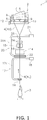
- FIG. 1 is a schematic front diagram illustrating a yarn winding section of an automatic winder in the first embodiment.
- the automatic winder 1 includes a yarn winding section 2.
- the yarn winding section 2 is a device configured to traverse a yarn 4, which is unwound from a yarn supplying bobbin 3, to wind the yarn 4 around a winding tube 6 (one example of a winding member), thereby forming yarn layers, i.e., a cone-shaped package 7.
- a yarn winding section 2 is illustrated in Fig. 1
- the automatic winder 1 is constituted by a plurality of yarn winding sections 2 located on a machine base (not shown).
- the winding tube 6 is a winding member having both ends flangeless. Although the winding tube 6 is cone-shaped, it may be cylindrical. In addition, the winding tube 6 has no initial level difference.
- the yarn supplying bobbin 3 which is attached to a tray, is supplied to the yarn winding section 2 by a conveyor (not shown), and is dispelled after the yarn winding operation.
- the yarn winding section 2 as one example of a winding section, includes a cradle 8 (one example of a rotation support section) that detachably supports the winding tube 6, and a yarn guide section 12 that guides the yarn 4 to the winding tube 6.
- the yarn guide section 12 includes a traverse drum 5, which rotates at a certain speed contacting a peripheral surface of the winding tube 6 or a peripheral surface of the package 7.
- the cradle 8 supports both ends of the winding tube 6 by rotatably holding them.
- the cradle 8 can tilt around a rotational axis 10 so that winding thickening (increase of the yarn layer in diameter) accompanying the yarn 4 winding around the winding tube 6 or the package 7 can be absorbed by the rotation of the cradle 8.
- the winding tube 6 or the package 7 rotates following up the traverse drum 5 by roll and contact.
- the traverse drum 5 rotates the package 7 as well as traverses the yarn 4 on the surface of the package 7.
- the traverse drum 5 is driven for rotation by a package driving mechanism 41 ( Fig. 8 ).
- the package driving mechanism 41 includes a motor and a power transmission mechanism.
- the traverse drum 5 has a peripheral surface on which spiral traverse grooves 9 are formed.
- the yarn 4 is wound around the peripheral surface of the winding tube 6 while the yarn 4 is traversed by the traverse grooves 9 with a constant width, thereby forming the package 7.
- a unit control section 50 ( Fig. 8 ), which controls the yarn winding section 2, is provided at each of the yarn winding sections 2.
- the yarn winding section 2 includes a yarn splicing device 14, a yarn clearer 15, a waxing device 24, a cleaning pipe 25, along a yarn travelling path between the yarn supplying bobbin 3 and the traverse drum 5 in the above-described order from the yarn supplying bobbin 3 side.
- the yarn splicing device 14 joins a lower yarn 4L as the yarn 4 from the yarn supplying bobbin 3 and an upper yarn 4U as the yarn from the package 7 after a yarn cut when the yarn clearer 15 detects a yarn defect and cuts the yarn 4, or after a yarn breakage of the yarn 4 from the yarn supplying bobbin 3.
- the yarn clearer 15 is a device that detects a thickness of the yarn 20 and includes a sensor for detecting a thickness of the yarn 20 passing a detecting portion of the yarn clearer 15, and an analyzer (not shown) for processing a yarn thickness signal from the sensor.
- the yarn clearer 15 detects a yarn defect such as slub by monitoring the yarn thickness signal from the sensor.
- the yarn clearer 15 includes a cutter 16 with which the yarn 4 is immediately cut when a yarn defect is detected.
- a lower yarn sucking, catching, and guiding mechanism 17 for sucking, catching, and guiding the lower yarn 4L on the yarn supplying bobbin 3 side to the yarn splicing device 14 is provided below the yarn splicing device 14.
- An upper yarn sucking, catching, and guiding mechanism 20 (suction section) for sucking, catching, and guiding the upper yarn 4U on the package 7 side to the yarn splicing device 14 is provided above the yarn splicing device 14.
- the upper yarn sucking, catching, guiding mechanism 20 is shaped like a pipe and includes an air suction mouth 22 at the tip thereof.
- the upper yarn sucking, catching, guiding mechanism 20 is composed of a pipe 20a extending from the suction mouth 22 and a shaft 21 that rotatably supports the pipe 20a.
- the pipe 20a is connected to a shutter device (not shown) via a coupling pipe (not shown).
- the base end of the upper yarn sucking, catching, guiding mechanism 20 is connected to a blower (not shown) via the shutter device (not shown).
- the lower yarn sucking, catching, guiding mechanism 17 is also shaped like a pipe and includes an air suction port 19 at the tip thereof.
- the lower yarn sucking, catching, guiding mechanism 17 is composed of a relay pipe 17a configured to be pivotally movable around a shaft 18, and a coupling pipe (not shown) that couples the relay pipe 17a to a blower duct (not shown).
- the waxing device 24 applies appropriate wax to the traveling yarn 4.
- the cleaning pipe 25 sucks and removes foreign matter attached to the traveling yarn 4.
- a base end of the cleaning pipe 25 is connected to the blower via the shutter device (not shown).
- a suction port is formed at the tip of the cleaning pipe 25. The suction port of the cleaning pipe 25 is located in proximity to the yarn 4 traveling between the waxing device 24 and the traverse drum 5.
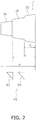
- Fig. 2 is a schematic diagram illustrating a package.
- Fig. 3 is a schematic sectional diagram illustrating the package.
- the package 7 is cone-shaped with steps, and has 3 steps in this embodiment. Specifically, it includes a first step 7A (one example of a first portion) having the smallest diameter, a second step 7B (one example of a second portion) having the middle diameter, and a third step 7C having the largest diameter.
- the package 7 includes a first yarn layer 51, a second yarn layer 53, and a third yarn layer 55, which are alternately formed.
- the first yarn layer 51 is formed as a whole in the width direction (from the first step 7A to the third step 7C).
- the second yarn layer 53 is formed on one side of the first yarn layer 51 in the width direction (over the second step 7B to the third step 7C) with a width narrower than that of the first yarn layer 51.
- the third yarn layer 55 is formed on one side of the second yarn layer 53 in the width direction (at the third step 7C) with a width narrower than that of second yarn layer 53.
- the first step 7A is constituted by the first yarn layers 51
- the second step 7B is constituted by the first yarn layers 51 and the second yarn layers 53
- the third step 7C is constituted by the first yarn layers 51, the second yarn layers 53, and the third yarn layers 55.
- the first yarn layer 51 is wound with a width (A) from a reference end (P) close to the figure right side
- the second yarn layer 53 is wound with a width (B), which is narrower than the first yarn layer 51, from the reference end on figure right side
- the third yarn layer 55 is wound with a width (C), which is narrower than the second yarn layer 53, from the reference end on the figure right side.
- the outermost first yarn layer 51, the third yarn layer 55, the second yarn layer 53, the first yarn layer 51 are repeatedly unwound in this order.
- a stepped structure which includes the first step 7A and the second step 7B having different outer diameters, the yarn is unlikely to touch the yarn layer when unwound. Specifically, when the second step 7B is being unwound, the yarn never touches the first step 7A. As a result, unwinding tension is decreased.
- first yarn layer 51 and the second yarn layer 53 which constitute the first step 7A and the second step 7B of the yarn, are alternately layered. Accordingly, it is possible to realize the yarn winding by which a dangerous zone of latching is avoided.
- the boundaries between the steps are smoothly changed, i.e., no angular portions are formed on the surface.
- the reason is that the first yarn layer 51 continuously covers a level difference portion of the second yarn layer 53 from the first step 7A to the second step 7B, the first yarn layer 51 continuously covers the level difference portion of the second yarn layer 53 from the second step 7B to the third step 7C, and the second yarn layer 53 continuously covers the level difference portion of the third yarn layer 55 from the second step 7B to the third step 7C.
- the yarn winding section 2 includes a yarn winding width adjustment device 61.
- the yarn winding width adjustment device 61 restricts the yarn 4 being traversed so as to move the yarn 4 along the traverse grooves 9 different from the previous ones, so that a yarn layer is formed on the winding tube 6 with a width narrower than that in the non-restriction case.
- the yarn winding width adjustment device 61 includes, as shown in Fig. 2 , a lever member 62.
- the lever member 62 includes, as a plurality of lever members, a first guide lever 63 and a second guide lever 65.
- the first guide lever 63 and the second guide lever 65 are provided close to a yarn guiding side of the traverse drum 5.
- the first guide lever 63 and the second guide lever 65 are located corresponding to different positions in the rotational axis direction of the traverse drum 5, specifically, from the figure left side to the right in the above-described order.
- the first guide lever 63 and the second guide lever 65 can move between a restriction position and a non-restriction position.
- the restriction position the first guide lever 63 and the second guide lever 65 restrict a movable position of the yarn in the rotational axis direction of the traverse drum 5 in a yarn traverse passing area so as to guide the yarn 4 to the traverse drum 5 with a narrow traverse width.
- the non-restriction position the first guide lever 63 and the second guide lever 65 do not restrict a movable position of the yarn in the rotational axis direction of the traverse drum by going out of the yarn traverse passing area so as to guide the yarn to the traverse drum 5 with a wide traverse width.
- the first guide lever 63 and the second guide lever 65 guide the yarn 4 to the different traverse grooves 9 of the traverse drum 5 depending on whether they are positioned at the restriction position or the non-restriction position (later described).
- the yarn winding width adjustment device 61 includes a traverse forming mechanism 43 ( Fig. 8 ) that controls the operation of the first guide lever 63 and the second guide lever 65 (later described).
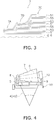
- Fig. 4 is a schematic front diagram illustrating a first yarn winding operation.
- Fig. 5 is a schematic front diagram illustrating a second yarn winding operation.
- Fig. 6 is a schematic front diagram illustrating a third yarn winding operation.
- the first guide lever 63 and the second guide lever 65 are located at the non-restriction positions, so that the yarn 4 is not restricted and is guided to the traverse drum 5 with the widest traverse width. As a result, the first yarn layer 51 is formed.
- FIG. 7 is an exploded diagram of the traverse drum.
- the rotational direction of the traverse drum 5 is indicated by an arrow (R).
- the traverse grooves of the traverse drum 5 are formed spiral, and mainly include a traverse outward route 71 and a traverse homeward route 73.
- the traverse outward route 71 extends leftward and diagonally downward in the figure and is shown as three grooves. In other words, the traverse outward route 71 extends so as to widen the path of the yarn leftward in the figure (on a first side in the width direction) when the yarn 4 is guided by the grooves.
- the traverse outward route 71 extends in the following order: point (a); point (b); point (c); and point (d).
- the traverse homeward route 73 extends rightward and diagonally downward in the figure, and is indicated as two grooves. In other words, the traverse homeward route 73 extends so as to narrow the path of the yarn toward the figure right side of the traverse drum 5 (on a second side in the width direction). Specifically, in Fig. 7 , the traverse homeward route 73 extends in the following order: point (d); point (e); and point (a).
- the traverse outward route 71 and the traverse homeward route 73 include a first intersection 75 and a second intersection 77.
- the first intersection 75 is provided at a position about 2/3 from the right end of the drum width in Fig. 7 .
- the second intersection 77 is provided at a position about 1/3 from the right end of the drum width in Fig. 7 .
- the width range within which the yarn 4 travels along the traverse grooves 9 on the traverse drum 5 is the entire drum width (6 inches, for example), which is shown as width (A).
- the range within which the yarn travels along the traverse grooves 9 on the traverse drum 5 is the right end of the traverse drum 5 and the first intersection 75 (4 inches, for example), which is shown as width (B).
- the width range within which the yarn 4 travels along the traverse grooves 9 on the traverse drum 5 is between the right end of the traverse drum 5 and the second intersection 77 (3 inches, for example), which is shown as width (C).
- Fig. 8 is a block diagram illustrating the control configuration of the automatic winder.
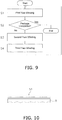
- Fig. 9 is a flowchart for explaining the yarn winding operation.
- the yarn winding section 2 includes a unit control section 50.
- the unit control section 50 is a computer system including a processor (e.g. a CPU), a storage device (e.g. a ROM, a RAM, an HDD, an SSD, and the like), and various interfaces (e.g. an A/D converter, a D/A converter, a communication interface, and the like).
- the unit control section 50 executes a program stored in a storage unit (corresponding to a part or the whole of storage area of the storage device) so as to perform various control operations.
- the unit control section 50 may be constituted of a single processor or may be constituted of a plurality of processors independent of each other for individual controls.
- a part or the whole of functions of individual elements of the unit control section 50 may be realized as a program that can be executed by the computer system constituting the control unit.
- a part of functions of individual elements of the control unit may be constituted of a custom IC.
- the above-described package driving mechanism 41 is connected to the unit control section 50.
- the above-described traverse forming mechanism 43 is connected to the unit control section 50.
- the traverse forming mechanism 43 is one for forming the package 7 with steps.
- the traverse forming mechanism 43 includes a first driving mechanism 45 (one example of a driving portion), a second driving mechanism 47 (one example of a driving portion), and a rotation sensor 59.
- the first driving mechanism 45 is an actuator for moving the first guide lever 63 between the restriction position and the non-restriction position, and is a solenoid, for example.
- the first driving mechanism 45 may be a motor or a power transmission mechanism.
- the second driving mechanism 47 is an actuator for moving the second guide lever 65 between the restriction position and the non-restriction position, is a solenoid, for example.
- the second driving mechanism 47 may be a motor or a power transmission mechanism.
- the rotation sensor 59 is one that outputs a signal each time the traverse drum 5 rotates by 1/60 rotation.
- a sensor for detecting the location of the yarn 4 sensors and switches for detecting conditions of the devices, and information input devices (not shown) are connected.
- Control flowchart is illustrative to be described below, each step may be omitted and replaced if necessary. Also, two or more steps can be performed simultaneously, may cause some or all runs overlapping.
- each block of the control flow chart is not limited to a single control operation, it can be replaced by a plurality of control operations represented by a plurality of blocks.
- Operation of the device is the result of a command to each device from the control unit, which are represented by the respective steps in a software application.
- Drum winding number is number of revolutions of the traverse drum while one traverse is performed (i.e., the yarn reciprocates between both ends of the drum grooves). Therefore, the drum winding number has different number of revolutions of the drum required for one traverse (the yarn reciprocating along the drum one time). Therefore, signal input number from the rotation sensor 59 are different from each other.
- drum winding number drum rotational number/trv
- drum rotation signal input number/trv drum rotation signal input number/trv
- the drum winding number (the number of winding) is determined, and how many drum rotations are necessary for one traverse is determined. Accordingly, for each winding number, a guide lever can move between the restriction position and the non-restriction position at a proper timing.
- Step S2 it is determined whether or not the package 7 is completed. If it is not completed, the process shifts to Step S3. If it is completed, the process is finished.
- the first yarn layer 51, the second yarn layer 53, and the third yarn layer 55 are repeatedly formed, and the first yarn layer 51 is finally formed, thereby completing the package 7.
- the unit control section 50 executes the above-described steps depending on one of the predetermined winding pattern information. Specifically, the unit control section 50, automatically or following the instructions from an operator, reads the winding pattern information stored in a memory, and executes the control based on it. Accordingly, the package manufacturing operation becomes simple. As a modification, an operator can input the winding pattern into the unit control section 50 every time.
- a step of winding the first yarn layer 51 around the winding tube 6, a step of winding the second yarn layer 53 over the first yarn layer 51 in a range in the longitudinal direction of the winding tube 6 shorter than the first yarn layer 51, and a step of winding the third yarn layer 55 over the second yarn layer 53 in the longitudinal direction of the winding tube 6 shorter than the second yarn layer 53, are alternately repeated.
- a yarn layer is formed which has a first step 7A, a second step 7B and a third step 7C.
- the second step 7B and the third step 7C are arranged with the first step 7A in the longitudinal direction of the winding tube 6.
- the second step 7B has a diameter larger than that of first step 7A.
- the third step 7C has a diameter larger than that of the second step 7B.
- the first yarn layer with a wide winding width and the second yarn layer with a narrow winding width can be formed, for example. Therefore, as the present embodiment, the yarn layer with a narrow winding width and the yarn layer with a wide winding width can be combined with each other on one package, thereby obtaining the package 7 with stepped portions.
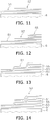
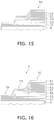
- FIG. 10 through Fig. 16 are schematic sectional diagrams illustrating the yarn winding operations.
- the first yarn layer 51 is formed over the entire surface of the winding tube 6 (Step S1 in Fig. 9 ).
- the second yarn layer 53 is formed over the first yarn layer 51 (Step S3 in Fig. 9 ).
- the third yarn layer 55 is formed on the second yarn layer 53 (Step S4 in Fig. 9 ).
- the first yarn layer 51 is formed on the previous first yarn layer 51, the second yarn layer 53 and the third yarn layer 55 (Step S1 in Fig. 9 ).
- the second yarn layer 53 is formed on the first yarn layer 51 (Step S3 in Fig. 9 ).
- the third yarn layer 55 is formed on the second yarn layer 53 (Step S4 in Fig. 9 ).
- the first yarn layer 51 is formed on the third yarn layer 55 (Step S1 in Fig.9 ). As a result, the package 7 is finished.
- the first yarn layer 51 covers the level difference portion between the second yarn layer 53 and the third yarn layer 55, change in height of the yarn layer at the level difference portion is decreased, so that the height changes gently. Accordingly, the number of the yarn layers can be increased, and the weight of the package 7 can be increased.
- first yarn layer 51 the second yarn layer 53 and the third yarn layer 55 can be repeated three times or more although that is twice in the above-described embodiment.
- the number of kinds of the yarn layers constituting repeated set can be two or four or more although that is three in the above-described embodiment.
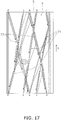
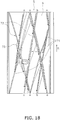
- FIG. 17 through Fig. 19 are exploded diagrams of the grooves on the traverse drum for illustrating the travelling of the yarn along the grooves in the yarn winding operations.
- the first yarn winding operation (step S1 in Fig. 9 )
- the yarn 4 travels along the traverse grooves 9 of the traverse drum 5 in the following order: point (a); point (b); point (c); point (d); point (e); and point (a).
- the first guide lever 63 is positioned at the non-restriction position, the yarn 4, travelling along the traverse outward route 71, passes the first intersection 75 and continues to travel along the traverse outward route 71.
- the first yarn layer 51 is formed.
- the yarn 4 travels along the traverse grooves 9 of the traverse drum 5 in the following order: point (a); point (b); point (c); first intersection 75; point (e); and point (a). More specifically, since the first guide lever 63 is positioned at the restriction position, the yarn 4, which travels along the traverse outward route 71, shifts to the traverse homeward route 73 at the first intersection 75, and then travels along the traverse homeward route 73. As a result, the second yarn layer 53 is formed.
- the yarn 4 travels along the traverse grooves 9 of the traverse drum 5 in the following order: point (a); point (b); second intersection 77; and point (a). More specifically, since the second guide lever 65 is positioned at the restriction position, the yarn 4, which travels along the traverse outward route 71, shifts to the traverse homeward route 73 at the second intersection 77, and travels along the traverse homeward route 73 after that. As a result, the third yarn layer 55 is formed.
- the present invention can be applied to a package of a different size.
- the present invention can be applied to a package with a winding width of 4 inches.
- FIG. 20 is a schematic front diagram illustrating the structure of the cradle in the second embodiment.
- the cradle 8 has a support potion 8a at one end, to which an adaptor 83 is detachably attached.
- the adaptor 83 supports the end portion of the winding tube 6. According, it is possible to attach winding tubes 6 with different lengths to the cradle 8.
- the adaptor may be provided at another support end of the cradle, or both support end portions of the cradle, as modifications.
- Fig. 21 is a schematic front diagram illustrating the yarn winding section of the automatic winder in the third embodiment.
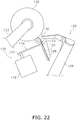
- Fig. 22 is a schematic side diagram of the traverse device.
- a yarn winding section 100 includes a yarn unwinding assisting device 112, a tensioning device 113, a yarn splicing device 114, and a yarn monitoring device 115, which are arranged along a yarn travelling path between a yarn supplying bobbin 121 and a contact roller 129, in this order from the yarn supplying bobbin 121.
- a yarn feeding section 111 is provided.
- the yarn feeding section 111 holds the yarn supplying bobbin 121 at a certain position, which is transported by a bobbin transportation system (not shown).
- the yarn unwinding assisting device 112 lowers the restricting member 140 covering a core tube of the yarn supplying bobbin 121 accompanying unwinding of a yarn 120 from the yarn supplying bobbin 121 in order to assist unwinding of the yarn 120 from the yarn supplying bobbin 121.
- the tensioning device 113 applies predetermined tension to the travelling yarn 120.
- the yarn splicing device 114 splices a lower yarn from the yarn supplying bobbin 121 side and an upper yarn from a package 130 side.
- the yarn monitoring device 115 includes a head 149 and an analyzer (not shown).
- the head 149 includes a sensor (not shown) which detects the thickness of the yarn 120.
- the analyzer processes a yarn thickness signal transmitted from this sensor.
- the yarn monitoring device 115 monitors the yarn thickness signal transmitted from the sensor in order to detect a yarn defect such as a slub.
- a cutter 139 is arranged in the vicinity of the head 149. The cutter 139 cuts the yarn 120 immediately after the yarn monitoring device 115 detects a yarn defect.
- a lower yarn catching member 125 is provided below the yarn splicing device 114 to catch and guide a yarn end section of the lower yarn to the yarn splicing device 114.
- An upper yarn catching member 126 is provided above the yarn splicing device 114 to catch and guide a yarn end section of the upper yarn to the yarn splicing device 114.
- the lower yarn catching member 125 includes a lower yarn pipe arm 133, and a lower yarn suction mouth 132 formed at a tip end of the lower yarn pipe arm 133.
- the upper yarn catching member 126 includes an upper yarn pipe arm 136, and an upper yarn suction mouth 135 formed at a tip end of upper yarn pipe arm 136.
- the lower yarn pipe arm 133 and the upper yarn pipe arm 136 can swing around a shaft 134 and a shaft 137, respectively.
- Appropriate negative-pressure sources are connected to the lower yarn pipe arm 133 and the upper yarn pipe arm 136, respectively.
- the lower yarn pipe arm 133 is configured such that suction airflow is generated at the lower yarn suction mouth 132 in order to suck and catch the yarn end section of the lower yarn.
- the upper yarn pipe arm 136 is configured such that suction airflow is generated at the upper yarn suction mouth 135 in order to suck and catch the yarn end section of the upper yarn.
- a shutter (not shown) is provided close to each of the base ends of the lower yarn pipe arm 133 and the upper yarn pipe arm 136. The shutters can be opened and closed in response to signals from the unit control section 150. Accordingly, the suction flows from the lower yarn suction mouth 132 and the upper yarn suction mouth 135 are controlled for the stop and generation.
- the yarn winding section 100 includes a cradle 123 and a contact roller 129.
- the cradle 123 removably supports the winding bobbin 122.
- the contact roller 129 can rotate while making contact with the peripheral surface of the winding bobbin 122 or the peripheral surface of the package 130.
- the yarn winding section 100 includes an arm-type traverse device 170 for traversing the yarn 120.
- the traverse device 170 is located in the vicinity of the cradle 123. In the yarn winding section 100, the yarn 120 can be wound into the package 130 while being traversed by the traverse device 170.
- a guide plate 128 is provided a little upstream of the traverse portion. The guide plate 128 guides the upstream yarn 120 to the traverse portion.
- a ceramic traverse fulcrum 127 is provided further upstream of the guide plate 128.
- the traverse device 170 traverses the yarn 120 using the traverse fulcrum 127 as a fulcrum.
- the cradle 123 can swing around a swing shaft 148.
- An increase in a diameter of yarn layers accompanying winding of the yarn 120 around the winding bobbin 122 is absorbed by swinging of the cradle 123.
- a rotational speed sensor 124 is provided at the cradle 123 for measuring the rotational speed of the package 130.
- a package driving motor 141 e.g., a servo motor, is attached to the cradle 123.
- the motor 141 rotates the winding bobbin 122 to wind the yarn 120 around the winding bobbin 122.
- the package driving motor 141 can rotate the package 130 (the winding bobbin 122) in a forward rotation in which the package 130 is rotated in the winding direction.
- the package driving motor 141 can rotate the package 130 in a reverse rotation in which the package 130 is rotated in an anti-winding direction, which is a direction opposite of the winding direction.
- the package driving motor 141 has a motor shaft unrotatably connected to the winding bobbin 122 when the winding bobbin 122 is supported by the cradle 123.
- the operation of the package driving motor 141 is controlled by a package driving control section (not shown).
- the package driving control section controls the package driving motor 141 to operate and stop in response to operation signals from the unit control section 150.
- the traverse device 170 includes, as shown in Fig. 22 , a traverse driving motor 176, an output shaft 177, and a traverse arm 174.
- the traverse driving motor 176 drives the traverse arm 174, and is a servomotor, for example.
- the operation of the traverse driving motor 176 is controlled by a traverse control section (not shown).
- the traverse control section (not shown) includes a hardware device provided with a dedicated microprocessor or the like.
- the traverse control section controls the traverse driving motor 176 to operate and stop in response to signals from the unit control section (not shown).
- the power of the traverse driving motor 176 is, as shown in Fig. 22 , transmitted to a base portion of the traverse arm 174 via the output shaft 177.
- the rotor of the driving motor 176 is rotated forward and backward so that the traverse arm 174 is reciprocated in the winding width direction of the package 130 in a circular trajectory.
- a yarn guide mechanism 173 is formed in a hook shape.
- the traverse arm 174 can guide the yarn 120 using the yarn guide mechanism 173. While the yarn guide mechanism 173 is guiding the yarn 120, the traverse arm 174 is reciprocated in a circular trajectory to traverse the yarn 120.
- the traverse control section (not shown) controls the traverse driving motor 176 so that the traverse arm 174 traverses the yarn 120. This control operation makes it possible to form the package 130 with the stepped portions as in the first embodiment.
- the shape of the package may be cone-shaped (truncated cone-shape) or cheese-shaped (cylindrical).
- the number of the guide levers is two in the first embodiment and a package with three steps is manufactured, the number of the guide levers is not limited. For example, only one guide lever can be used to manufacture a package with two steps. The number of the guide levers may be three or more.
- the number of the guide levers positioned at the restriction position at one time is one in the first embodiment, this number is not limited.
- the number of the guide levers moving to the restriction position at one time may be two. In this case, the traverse width of the yarn is limited between the two guide levers.
- the present invention can also be applied to a spinning machine and an open-end spinning machine.
- the present invention can be widely applied to a package, a package manufacturing method, and a yarn winding device.
Landscapes
- Winding Filamentary Materials (AREA)
- Filamentary Materials, Packages, And Safety Devices Therefor (AREA)
Abstract
Description
- The present invention relates to a package, a package manufacturing method, and a yarn winding device.
- Conventionally, an automatic winder has been known that unwinds a yarn from a yarn supplying bobbin manufactured by a spinning machine, while removing yarn defects such as slub, and splices the yarn of the yarn supply bobbins to manufacture one package.
- Furthermore, a winding member on which a special yarn such as glass fiber and carbon fiber is wound has been also known (Refer to Patent Citation 1 and Patent Citation 2, for example).
- In a yarn winding member as recited in
Patent Citation 1, the outer diameter is changed in a stepped way as shown inFig. 2 andFig. 7 , although it is not a package using spun yarn. - The winding member recited in Patent Citation 2 employs annealed low-carbon steel wires and metal wires, and the winding is considered whether the wound yarn layer reaches the bottom flange or the upper flange. Furthermore, a first series of layers forms a conical basis of an elongated material on the core where the elongated material is present at the bottom flange in a larger amount than at the top flange, thereby forming a conical base made of the elongated material on the core. A second series of layers is wound around the conical base, and extends from the bottom flange to the top flange such that the conical shape of the elongated material is kept.
-
- Patent Citation 1: Japanese Patent
2780336 - Patent Citation 2:
US 2017/81143 A1 - The winding in Patent Citation 2 may be appropriate for low-carbon steel wires and metal wires, but it is not preferable for a package from natural fiber such as cotton.
- In contrast, for a package using spun yarn, it is desired to improve unwindablity. The reason is that the winding speed of the package has become higher than in the past. The reason lowering the unwindability are a latching in which the yarn suffers from tension breakage due to fluff entanglement or waste yarn contamination. If the unwinding tension is high, a yarn is broken at a weak yarn portion even though there is no apparent defect phenomenon.
- It has been further requested to suppress the latching in a package using a yarn of a yarn supplying bobbin manufactured by a spinning machine.
- It is an object of the present invention to improve unwindability of the package and to suppress the latching.
- Aspects are explained below as the technical solution. These aspects can be arbitrarily combined as needed.
- A package according to the present invention includes a winding member with no initial level difference and having flangeless both ends, and a yarn wound around the winding member. "Flangeless both ends" means that a flange is not formed either on one or on another end of a main body of the winding member. The yarn includes a first portion and a second portion arranged with each other in a longitudinal direction of the winding member. The second portion has a yarn layer with a diameter larger than that of the first portion.
- The yarn includes a first yarn layer wound at the first portion and the second portion with a first width from a reference end of the winding member, and a second yarn layer layered alternately with the first yarn layer. The second yarn layer is wound only at the second portion with a second width from the reference end of the winding member narrower than the first width.
- In this package, the yarn is wound around the flangeless winding member. In a case where the winding member has flanges unlike the present invention, when natural fibers are unwound, the flange rubs against the yarn, so that natural fiber becomes fluffy.
- Natural fibers such as cotton have a thin yarn and the yarn is wound into package with a large diameter. Therefore, in a case the first yarn layer and the second yarn are not wound alternately unlike the present invention, the level difference is smoothened and disappears. In contrast, according to the present invention, the first yarn layer and the second yarn layer are alternately wound, so that a package with the level difference is formed even if a package employs a natural fiber.
- In this package, a stepped structure is realized which has the first portion and the second portion having different outer diameters. Accordingly, the yarn is unlikely to touch the yarn layer when the yarn is unwound. Specifically, when the yarn at the large diameter portion is unwound, the yarn does not touch a portion having a smaller diameter. As a result, the unwinding tension is reduced.
- In addition, the first yarn layer and the second yarn layer, which constitute the first portion and the second portion of the yarn, are alternately layered. Accordingly, it is possible to realize a yarn winding that can avoid the dangerous zone of the latching.
- The first yarn layer may continuously cover a level difference portion of the second yarn layer from the first portion to the second portion. Accordingly, the change in height of the yarn layer at the level difference portion becomes gentle. As a result, it is possible to increase the number of the yarn layers, and to increase the weight of the package.
- The yarn may include a third portion arranged with the second portion in the longitudinal direction of the winding member. The third portion has a yarn layer with a diameter larger than that of the second portion.
- The yarn may include a third layer wound alternately layered with the first yarn layer and the second yarn layer. The third layer may be wound only at the third portion with a third width from the reference end of the winding member narrower than that of the second width.
- A ratio of traverse numbers of the first yarn layer, the second yarn layer, and the third yarn layer may be 2: 3: 4.
- Drum winding numbers for forming the first yarn layer, the second yarn layer, and the third yarn layer are 2.5w: 2.0w: 1.5w, respectively.
- The ratio of traverse numbers of the first yarn layer, the second yarn layer, and the third yarn layer may be 1: 2: 2.
- Drum winding numbers for forming the first yarn layer, the second yarn layer, and the third yarn layer may be 2.0w: 1.5w: 1.5w.
- Widths of the first yarn layer, the second yarn layer, and the third yarn layer may be 4 inches: 3.8 inches: 3 inches, respectively.
- A method of manufacturing a package according to another aspect of the present invention is a method of manufacturing a package having a yarn wound around a winding member having both ends flangeless.
- The method includes the following steps:
- a step of winding a first yarn layer around the winding member; and
- a step of winding a second yarn layer within a range narrower than the first yarn layer in a longitudinal direction of the winding member.
- The both steps are repeated alternately to make a yarn layer having a first portion and a second portion arranged with each other in the longitudinal direction of the winding member, and the second portion has a diameter larger than that of the first portion.
- In this package manufacturing method, a package with steps is formed that includes the first portion and the second portion of the yarn with different outer diameters. Accordingly, when the yarn is unwound, the number of yarn layers with which the yarn gets in touch decreases. Specifically, when the large diameter portion is being unwound, the yarn never touches a portion having a smaller diameter. As a result, the unwinding tension is decreased.
- In addition since the first yarn layer and the second yarn layer are alternately layered that constitute the first portion and the second portion of the yarn, it is possible to realize the yarn winding avoiding the dangerous zone of the latching.
- A yarn winding device according to a further aspect of the present invention includes a winding section, and a control section configured to control the winding section to perform the method of manufacturing the package.
- In this device, the above-described effects can be obtained.
- The winding section may include a rotation support section, a yarn guide section, and a lever member.
- The rotation support section may be one to which the winding member is attached.
- The yarn guide section is configured to guide a yarn to the winding member. The yarn guide unit has a traverse drum.
- The lever member is configured to move between a non-restriction position and a restriction position. At the non-restriction position, the lever member does not restrict a movable position of the yarn in a rotational axis direction of the traverse drum to guide the yarn to the traverse drum with a wide traverse width. At the restriction position, the lever member restricts a movable position of the yarn in the rotational axis direction of the traverse drum to supply the yarn to the traverse drum with a narrow width, thereby guiding the yarn to different traverse grooves of the traverse drum between the restriction position and the non-restriction position. "Different traverse grooves" means the grooves are not totally the same.
- The control section controls the lever member to be located at the non-restriction position to perform the step of winding the first yarn layer, and controls the lever member to be located at the restriction position to perform the step of winding the second yarn layer.
- In this device, by moving the lever member between the restriction position and the non-restriction position, it is possible to change the traverse width of the yarn guided by the traverse drum. Specifically, when the lever member is at the non-restriction position, the yarn is guided to the traverse drum with a wide traverse width. When the lever member is positioned at the restriction position, the yarn is guided to the traverse drum with a narrow traverse width to pass through drum grooves different from that in a non-restricted state. Accordingly, it is possible to form a yarn layer with the wide winding width and a yarn layer with the narrow winding width. Accordingly, a yarn layer with the narrow winding width and a yarn layer with the wide winding width can be formed in one package.
- The lever member may include a plurality of lever members provided corresponding to different positions of the traverse drum in a rotational axis direction thereof. In this device, if the number of the lever members is two, three kinds of winding widths can be obtained.
- Below, one example will be explained where a first lever member and a second lever member are provided as a lever member. For example, the first lever member is positioned within the original traverse width of the yarn, and restricts the yarn from further moving at the restriction position to shorten the traverse width of the yarn. The second lever member is positioned within the original traverse width, and restricts the yarn from further moving at the restriction position to further shorten the traverse width of the yarn. In other words, the traverse width of the yarn becomes shorter as one of the turn positions shifts in the following order: the original position, the first lever member, and the second lever member. Accordingly, the yarn supplied from the traverse drum to the winding member forms a yarn layer with the widest width, a yarn layer having one end corresponding to one end of the previous one and overlapping the previous one partially in the drum width direction with the middle width, and a yarn layer having one end corresponding to one end of the previous one as a reference end, and partially overlapping the previous one in the drum width direction with the narrowest width.
- According to a package, a package manufacturing method, and a yarn winding device of the present invention, the unwindability of the package is improved, and the latching is suppressed.
-
-
Fig. 1 is a schematic front diagram illustrating a yarn winding section of an automatic winder in the first embodiment. -
Fig. 2 is a schematic diagram illustrating a package. -
Fig. 3 is a schematic sectional diagram illustrating the package. -
Fig. 4 is a schematic front diagram illustrating a first yarn winding operation. -
Fig. 5 is a schematic front diagram illustrating a second yarn winding operation. -
Fig. 6 is a schematic front diagram illustrating a third yarn winding operation. -
Fig. 7 is an exploded diagram of the traverse drum. -
Fig. 8 is a block diagram illustrating the control configuration of the automatic winder. -
Fig. 9 is a flowchart for explaining the yarn winding operation. -
Fig. 10 is a schematic sectional diagram illustrating the first yarn winding operation. -
Fig. 11 is a schematic sectional diagram illustrating the second yarn winding operation. -
Fig. 12 is a schematic sectional diagram illustrating the third yarn winding operation. -
Fig. 13 is a schematic sectional diagram illustrating the first yarn winding operation. -
Fig. 14 is a schematic sectional diagram illustrating the second yarn winding operation. -
Fig. 15 is a schematic sectional diagram illustrating the third yarn winding operation. -
Fig. 16 is a schematic sectional diagram illustrating the first yarn winding operation. -
Fig. 17 is an exploded diagram of the grooves on the traverse drum for illustrating the travelling of the yarn along the grooves in the first yarn winding operation. -
Fig. 18 is an exploded diagram of the grooves on the traverse drum for illustrating the travelling of the yarn along the grooves in the second yarn winding operation. -
Fig. 19 is an exploded diagram of the grooves on the traverse drum for illustrating the travelling of the yarn along the grooves in the first yarn winding operation. -
Fig. 20 is a schematic front diagram illustrating the structure of the cradle in the second embodiment. -
Fig. 21 is a schematic front diagram illustrating the yarn winding section of the automatic winder in the third embodiment. -
Fig. 22 is a schematic side diagram of the traverse device. - According to
Fig. 1 , anautomatic winder 1 will be explained.Fig. 1 is a schematic front diagram illustrating a yarn winding section of an automatic winder in the first embodiment. - The
automatic winder 1 includes ayarn winding section 2. Theyarn winding section 2 is a device configured to traverse ayarn 4, which is unwound from ayarn supplying bobbin 3, to wind theyarn 4 around a winding tube 6 (one example of a winding member), thereby forming yarn layers, i.e., a cone-shapedpackage 7. Although only oneyarn winding section 2 is illustrated inFig. 1 , theautomatic winder 1 is constituted by a plurality ofyarn winding sections 2 located on a machine base (not shown). - It is noted that the winding
tube 6 is a winding member having both ends flangeless. Although the windingtube 6 is cone-shaped, it may be cylindrical. In addition, the windingtube 6 has no initial level difference. - The
yarn supplying bobbin 3, which is attached to a tray, is supplied to theyarn winding section 2 by a conveyor (not shown), and is dispelled after the yarn winding operation. - The
yarn winding section 2, as one example of a winding section, includes a cradle 8 (one example of a rotation support section) that detachably supports the windingtube 6, and ayarn guide section 12 that guides theyarn 4 to the windingtube 6. Theyarn guide section 12 includes atraverse drum 5, which rotates at a certain speed contacting a peripheral surface of the windingtube 6 or a peripheral surface of thepackage 7. - The
cradle 8 supports both ends of the windingtube 6 by rotatably holding them. In addition, thecradle 8 can tilt around arotational axis 10 so that winding thickening (increase of the yarn layer in diameter) accompanying theyarn 4 winding around the windingtube 6 or thepackage 7 can be absorbed by the rotation of thecradle 8. The windingtube 6 or thepackage 7 rotates following up thetraverse drum 5 by roll and contact. - The
traverse drum 5 rotates thepackage 7 as well as traverses theyarn 4 on the surface of thepackage 7. Thetraverse drum 5 is driven for rotation by a package driving mechanism 41 (Fig. 8 ). Thepackage driving mechanism 41 includes a motor and a power transmission mechanism. - The
traverse drum 5 has a peripheral surface on which spiraltraverse grooves 9 are formed. Theyarn 4 is wound around the peripheral surface of the windingtube 6 while theyarn 4 is traversed by thetraverse grooves 9 with a constant width, thereby forming thepackage 7. - A unit control section 50 (
Fig. 8 ), which controls theyarn winding section 2, is provided at each of theyarn winding sections 2. - The
yarn winding section 2 includes ayarn splicing device 14, ayarn clearer 15, awaxing device 24, a cleaningpipe 25, along a yarn travelling path between theyarn supplying bobbin 3 and thetraverse drum 5 in the above-described order from theyarn supplying bobbin 3 side. - The
yarn splicing device 14 joins alower yarn 4L as theyarn 4 from theyarn supplying bobbin 3 and anupper yarn 4U as the yarn from thepackage 7 after a yarn cut when theyarn clearer 15 detects a yarn defect and cuts theyarn 4, or after a yarn breakage of theyarn 4 from theyarn supplying bobbin 3. - The
yarn clearer 15 is a device that detects a thickness of theyarn 20 and includes a sensor for detecting a thickness of theyarn 20 passing a detecting portion of theyarn clearer 15, and an analyzer (not shown) for processing a yarn thickness signal from the sensor. Theyarn clearer 15 detects a yarn defect such as slub by monitoring the yarn thickness signal from the sensor. Theyarn clearer 15 includes acutter 16 with which theyarn 4 is immediately cut when a yarn defect is detected. - A lower yarn sucking, catching, and guiding
mechanism 17 for sucking, catching, and guiding thelower yarn 4L on theyarn supplying bobbin 3 side to theyarn splicing device 14 is provided below theyarn splicing device 14. An upper yarn sucking, catching, and guiding mechanism 20 (suction section) for sucking, catching, and guiding theupper yarn 4U on thepackage 7 side to theyarn splicing device 14 is provided above theyarn splicing device 14. - The upper yarn sucking, catching, guiding
mechanism 20 is shaped like a pipe and includes anair suction mouth 22 at the tip thereof. The upper yarn sucking, catching, guidingmechanism 20 is composed of apipe 20a extending from thesuction mouth 22 and ashaft 21 that rotatably supports thepipe 20a. Thepipe 20a is connected to a shutter device (not shown) via a coupling pipe (not shown). In other words, the base end of the upper yarn sucking, catching, guidingmechanism 20 is connected to a blower (not shown) via the shutter device (not shown). - The lower yarn sucking, catching, guiding
mechanism 17 is also shaped like a pipe and includes anair suction port 19 at the tip thereof. The lower yarn sucking, catching, guidingmechanism 17 is composed of arelay pipe 17a configured to be pivotally movable around ashaft 18, and a coupling pipe (not shown) that couples therelay pipe 17a to a blower duct (not shown). - The waxing
device 24 applies appropriate wax to the travelingyarn 4. - The cleaning
pipe 25 sucks and removes foreign matter attached to the travelingyarn 4. A base end of the cleaningpipe 25 is connected to the blower via the shutter device (not shown). A suction port is formed at the tip of the cleaningpipe 25. The suction port of the cleaningpipe 25 is located in proximity to theyarn 4 traveling between the waxingdevice 24 and thetraverse drum 5. - With reference to
Fig. 2 andFig. 3 , thepackage 7 will be explained.Fig. 2 is a schematic diagram illustrating a package.Fig. 3 is a schematic sectional diagram illustrating the package. - The
package 7 is cone-shaped with steps, and has 3 steps in this embodiment. Specifically, it includes afirst step 7A (one example of a first portion) having the smallest diameter, asecond step 7B (one example of a second portion) having the middle diameter, and athird step 7C having the largest diameter. - The
package 7 includes afirst yarn layer 51, asecond yarn layer 53, and athird yarn layer 55, which are alternately formed. Thefirst yarn layer 51 is formed as a whole in the width direction (from thefirst step 7A to thethird step 7C). Thesecond yarn layer 53 is formed on one side of thefirst yarn layer 51 in the width direction (over thesecond step 7B to thethird step 7C) with a width narrower than that of thefirst yarn layer 51. Thethird yarn layer 55 is formed on one side of thesecond yarn layer 53 in the width direction (at thethird step 7C) with a width narrower than that ofsecond yarn layer 53. In other words, thefirst step 7A is constituted by the first yarn layers 51, thesecond step 7B is constituted by the first yarn layers 51 and the second yarn layers 53, and thethird step 7C is constituted by the first yarn layers 51, the second yarn layers 53, and the third yarn layers 55. - In other words, the
first yarn layer 51 is wound with a width (A) from a reference end (P) close to the figure right side, thesecond yarn layer 53 is wound with a width (B), which is narrower than thefirst yarn layer 51, from the reference end on figure right side, and thethird yarn layer 55 is wound with a width (C), which is narrower than thesecond yarn layer 53, from the reference end on the figure right side. - When the yarn is unwound from the
package 7, the outermostfirst yarn layer 51, thethird yarn layer 55, thesecond yarn layer 53, thefirst yarn layer 51 are repeatedly unwound in this order. - As described above, since a stepped structure is realized which includes the
first step 7A and thesecond step 7B having different outer diameters, the yarn is unlikely to touch the yarn layer when unwound. Specifically, when thesecond step 7B is being unwound, the yarn never touches thefirst step 7A. As a result, unwinding tension is decreased. - In addition, the
first yarn layer 51 and thesecond yarn layer 53, which constitute thefirst step 7A and thesecond step 7B of the yarn, are alternately layered. Accordingly, it is possible to realize the yarn winding by which a dangerous zone of latching is avoided. - The boundaries between the steps are smoothly changed, i.e., no angular portions are formed on the surface. The reason is that the
first yarn layer 51 continuously covers a level difference portion of thesecond yarn layer 53 from thefirst step 7A to thesecond step 7B, thefirst yarn layer 51 continuously covers the level difference portion of thesecond yarn layer 53 from thesecond step 7B to thethird step 7C, and thesecond yarn layer 53 continuously covers the level difference portion of thethird yarn layer 55 from thesecond step 7B to thethird step 7C. - The
yarn winding section 2 includes a yarn winding width adjustment device 61. The yarn winding width adjustment device 61 restricts theyarn 4 being traversed so as to move theyarn 4 along thetraverse grooves 9 different from the previous ones, so that a yarn layer is formed on the windingtube 6 with a width narrower than that in the non-restriction case. - The yarn winding width adjustment device 61 includes, as shown in
Fig. 2 , alever member 62. Thelever member 62 includes, as a plurality of lever members, afirst guide lever 63 and asecond guide lever 65. Thefirst guide lever 63 and thesecond guide lever 65 are provided close to a yarn guiding side of thetraverse drum 5. Specifically, thefirst guide lever 63 and thesecond guide lever 65 are located corresponding to different positions in the rotational axis direction of thetraverse drum 5, specifically, from the figure left side to the right in the above-described order. - The
first guide lever 63 and thesecond guide lever 65 can move between a restriction position and a non-restriction position. At the restriction position, thefirst guide lever 63 and thesecond guide lever 65 restrict a movable position of the yarn in the rotational axis direction of thetraverse drum 5 in a yarn traverse passing area so as to guide theyarn 4 to thetraverse drum 5 with a narrow traverse width. At the non-restriction position, thefirst guide lever 63 and thesecond guide lever 65 do not restrict a movable position of the yarn in the rotational axis direction of the traverse drum by going out of the yarn traverse passing area so as to guide the yarn to thetraverse drum 5 with a wide traverse width. Thefirst guide lever 63 and thesecond guide lever 65 guide theyarn 4 to thedifferent traverse grooves 9 of thetraverse drum 5 depending on whether they are positioned at the restriction position or the non-restriction position (later described). - In this embodiment, since the number of the guide levers is two, it is possible to realize a
package 7 having three kinds of winding width (later described). - The yarn winding width adjustment device 61 includes a traverse forming mechanism 43 (
Fig. 8 ) that controls the operation of thefirst guide lever 63 and the second guide lever 65 (later described). - With reference to
Fig. 4 through Fig. 6 , the summary of the first through third yarn winding operation will be explained.Fig. 4 is a schematic front diagram illustrating a first yarn winding operation.Fig. 5 is a schematic front diagram illustrating a second yarn winding operation.Fig. 6 is a schematic front diagram illustrating a third yarn winding operation. - In the first yarn winding operation, as shown in
Fig. 4 , thefirst guide lever 63 and thesecond guide lever 65 are located at the non-restriction positions, so that theyarn 4 is not restricted and is guided to thetraverse drum 5 with the widest traverse width. As a result, thefirst yarn layer 51 is formed. - In the second yarn winding operation, as shown in
Fig. 5 , only thefirst guide lever 63 is positioned at the restriction position, so that theyarn 4 is restricted and is guided to thetraverse drum 5 with a middle-sized traverse width. Specifically, theyarn 4 is prevented from being traversed toward the figure left side (on a small diameter side of the package 7) by thefirst guide lever 63. As a result, thesecond yarn layer 53 is formed - In the third yarn winding operation, as shown in
Fig. 6 , only thesecond guide lever 65 is positioned at the restriction position, so that theyarn 4 is restricted and is guided to thetraverse drum 5 with the narrowest traverse width. Specifically, theyarn 4 is prevented from being traversed to the figure left side (on the small diameter side of the package 7) by thesecond guide lever 65. As a result, thethird yarn layer 55 is formed. - With reference to
Fig. 7 , the groove shape of thetraverse drum 5 will be explained.Fig. 7 is an exploded diagram of the traverse drum. The rotational direction of thetraverse drum 5 is indicated by an arrow (R). - The traverse grooves of the
traverse drum 5 are formed spiral, and mainly include a traverseoutward route 71 and a traversehomeward route 73. The traverse outward route 71 extends leftward and diagonally downward in the figure and is shown as three grooves. In other words, the traverse outward route 71 extends so as to widen the path of the yarn leftward in the figure (on a first side in the width direction) when theyarn 4 is guided by the grooves. Specifically, inFig. 7 , the traverse outward route 71 extends in the following order: point (a); point (b); point (c); and point (d). - The traverse homeward
route 73 extends rightward and diagonally downward in the figure, and is indicated as two grooves. In other words, the traverse homeward route 73 extends so as to narrow the path of the yarn toward the figure right side of the traverse drum 5 (on a second side in the width direction). Specifically, inFig. 7 , the traverse homeward route 73 extends in the following order: point (d); point (e); and point (a). - The traverse outward route 71 and the traverse homeward route 73 include a
first intersection 75 and asecond intersection 77. Thefirst intersection 75 is provided at a position about 2/3 from the right end of the drum width inFig. 7 . Thesecond intersection 77 is provided at a position about 1/3 from the right end of the drum width inFig. 7 . - According to the above-described structure, the
yarn 4, which has been traversed leftward in the figure at the traverse outward route 71, is then traversed rightward in the figure at the traverse homeward route 73, to the original position. Accordingly, theyarn 4, which is traversed by thetraverse grooves 9, is wound around the windingtube 6. - According to the above-described first yarn winding operation, the width range within which the
yarn 4 travels along thetraverse grooves 9 on thetraverse drum 5 is the entire drum width (6 inches, for example), which is shown as width (A). - According to the above-described second yarn winding operation, the range within which the yarn travels along the
traverse grooves 9 on thetraverse drum 5 is the right end of thetraverse drum 5 and the first intersection 75 (4 inches, for example), which is shown as width (B). - According to the above-described third yarn winding operation, the width range within which the
yarn 4 travels along thetraverse grooves 9 on thetraverse drum 5 is between the right end of thetraverse drum 5 and the second intersection 77 (3 inches, for example), which is shown as width (C). - With reference to
Fig. 8 andFig. 9 , the control configuration of theyarn winding section 2 will be explained.Fig. 8 is a block diagram illustrating the control configuration of the automatic winder.Fig. 9 is a flowchart for explaining the yarn winding operation. - The
yarn winding section 2 includes aunit control section 50. - The
unit control section 50 is a computer system including a processor (e.g. a CPU), a storage device (e.g. a ROM, a RAM, an HDD, an SSD, and the like), and various interfaces (e.g. an A/D converter, a D/A converter, a communication interface, and the like). Theunit control section 50 executes a program stored in a storage unit (corresponding to a part or the whole of storage area of the storage device) so as to perform various control operations. - The
unit control section 50 may be constituted of a single processor or may be constituted of a plurality of processors independent of each other for individual controls. - A part or the whole of functions of individual elements of the
unit control section 50 may be realized as a program that can be executed by the computer system constituting the control unit. Other than that, a part of functions of individual elements of the control unit may be constituted of a custom IC. - The above-described
package driving mechanism 41 is connected to theunit control section 50. - The above-described
traverse forming mechanism 43 is connected to theunit control section 50. Thetraverse forming mechanism 43 is one for forming thepackage 7 with steps. Thetraverse forming mechanism 43 includes a first driving mechanism 45 (one example of a driving portion), a second driving mechanism 47 (one example of a driving portion), and arotation sensor 59. - The
first driving mechanism 45 is an actuator for moving thefirst guide lever 63 between the restriction position and the non-restriction position, and is a solenoid, for example. Thefirst driving mechanism 45 may be a motor or a power transmission mechanism. - The
second driving mechanism 47 is an actuator for moving thesecond guide lever 65 between the restriction position and the non-restriction position, is a solenoid, for example. Thesecond driving mechanism 47 may be a motor or a power transmission mechanism. - The
rotation sensor 59 is one that outputs a signal each time thetraverse drum 5 rotates by 1/60 rotation. - To the
unit control section 50, a sensor for detecting the location of theyarn 4, sensors and switches for detecting conditions of the devices, and information input devices (not shown) are connected. - With reference to
Fig. 9 , a yarn winding operation of thepackage 7 will be explained. - Control flowchart is illustrative to be described below, each step may be omitted and replaced if necessary. Also, two or more steps can be performed simultaneously, may cause some or all runs overlapping.
- Further, each block of the control flow chart is not limited to a single control operation, it can be replaced by a plurality of control operations represented by a plurality of blocks.
- Operation of the device is the result of a command to each device from the control unit, which are represented by the respective steps in a software application.
- First, a method of determining the switching timing of the guide lever will be explained. Drum winding number is number of revolutions of the traverse drum while one traverse is performed (i.e., the yarn reciprocates between both ends of the drum grooves). Therefore, the drum winding number has different number of revolutions of the drum required for one traverse (the yarn reciprocating along the drum one time). Therefore, signal input number from the
rotation sensor 59 are different from each other. - The relationship between the drum winding number, drum rotational number/trv, drum rotation signal input number/trv is as follows, for example.
drum winding number drum rotational number/trv drum rotation signal input number/trv 2.5w 2.5 150 times 2.0w 2.0 120 times 1.5w 1.5 90 times - Accordingly, depending on the state of the guide lever (the restriction position or the non-restriction position), the drum winding number (the number of winding) is determined, and how many drum rotations are necessary for one traverse is determined. Accordingly, for each winding number, a guide lever can move between the restriction position and the non-restriction position at a proper timing.
- Below, with reference to
Fig. 9 , the formation of thepackage 7 will be explained wherein 2.5w (6 inches): 2.0w (4 inches): 1.5w (3 inches) = 2: 3: 4 (traverse number (layer number)). - At step S1, a first yarn winding operation is performed. Specifically, the
unit control section 50 controls thefirst guide lever 63 and thesecond guide lever 65 to move to the non-restriction position so as to set the drum winding number to 2.5w. Then, two yarn layers are formed in this state. When the drum rotation signals is input by 150 × 2 = 300 times, the formation of thefirst yarn layer 51 is finished. - At Step S2, it is determined whether or not the
package 7 is completed. If it is not completed, the process shifts to Step S3. If it is completed, the process is finished. - At Step S3, the second yarn winding operation is performed. Specifically, the
unit control section 50 controls thefirst guide lever 63 to the restriction position to switch the drum winding number to 2.0w. And three yarn layers are formed in this state. Then, when the drum rotation signal is input by 120×3 = 360 times, the formation of thesecond yarn layer 53 is finished. - At Step S4, the third yarn winding operation is performed. Specifically, the
unit control section 50 controls thefirst guide lever 63 to move to the non-restriction position and thesecond guide lever 65 to move to the restriction position, thereby switching the drum winding number to 1.5w. Then, four layers are formed in this state. Then, when the drum rotation signal is input by 90 × 4 = 360 times, the formation of thethird yarn layer 55 is finished. - As described above, the
first yarn layer 51, thesecond yarn layer 53, and thethird yarn layer 55 are repeatedly formed, and thefirst yarn layer 51 is finally formed, thereby completing thepackage 7. - It should be noted that the
unit control section 50 executes the above-described steps depending on one of the predetermined winding pattern information. Specifically, theunit control section 50, automatically or following the instructions from an operator, reads the winding pattern information stored in a memory, and executes the control based on it. Accordingly, the package manufacturing operation becomes simple. As a modification, an operator can input the winding pattern into theunit control section 50 every time. - In the above-described package manufacturing method, a step of winding the
first yarn layer 51 around the windingtube 6, a step of winding thesecond yarn layer 53 over thefirst yarn layer 51 in a range in the longitudinal direction of the windingtube 6 shorter than thefirst yarn layer 51, and a step of winding thethird yarn layer 55 over thesecond yarn layer 53 in the longitudinal direction of the windingtube 6 shorter than thesecond yarn layer 53, are alternately repeated. As a result, a yarn layer is formed which has afirst step 7A, asecond step 7B and athird step 7C. Thesecond step 7B and thethird step 7C are arranged with thefirst step 7A in the longitudinal direction of the windingtube 6. Thesecond step 7B has a diameter larger than that offirst step 7A. Thethird step 7C has a diameter larger than that of thesecond step 7B. - The operation of changing the width of the yarn layers will be explained in detail, as below. By moving the
first guide lever 63 and thesecond guide lever 65 between the restriction position and the non-restriction position, it is possible to change the traverse width of theyarn 4 being guided to thetraverse drum 5. Specifically, when thefirst guide lever 63 and thesecond guide lever 65 are positioned at the non-restriction positions, theyarn 4 is guided to thetraverse drum 5 with a wide traverse width. When thefirst guide lever 63 and thesecond guide lever 65 are at the restriction positions, theyarn 4 is guided to thetraverse drum 5 with a narrow traverse width, then passes traverse grooves different from that when not restricted, and theyarn 4 is wound around the windingtube 6 with a narrow winding width. Accordingly, the first yarn layer with a wide winding width and the second yarn layer with a narrow winding width can be formed, for example. Therefore, as the present embodiment, the yarn layer with a narrow winding width and the yarn layer with a wide winding width can be combined with each other on one package, thereby obtaining thepackage 7 with stepped portions. - With reference to
Fig. 10 through Fig. 16 , formation of the yarn layer in the above-described winding operation will be explained in detail.Fig. 10 through Fig. 16 are schematic sectional diagrams illustrating the yarn winding operations. - As shown in
Fig. 10 , as a first yarn winding operation, thefirst yarn layer 51 is formed over the entire surface of the winding tube 6 (Step S1 inFig. 9 ). - As shown in
Fig. 11 , as a second yarn winding operation, thesecond yarn layer 53 is formed over the first yarn layer 51 (Step S3 inFig. 9 ). - As shown in
Fig. 12 , as a third yarn winding operation, thethird yarn layer 55 is formed on the second yarn layer 53 (Step S4 inFig. 9 ). - As shown in
Fig. 13 , as the first yarn winding operation, thefirst yarn layer 51 is formed on the previousfirst yarn layer 51, thesecond yarn layer 53 and the third yarn layer 55 (Step S1 inFig. 9 ). - As shown in
Fig. 14 , as the second yarn winding operation, thesecond yarn layer 53 is formed on the first yarn layer 51 (Step S3 inFig. 9 ). - As shown in
Fig. 15 , as the third yarn winding operation, thethird yarn layer 55 is formed on the second yarn layer 53 (Step S4 inFig. 9 ). - As shown in
Fig. 16 , as the first yarn winding operation, thefirst yarn layer 51 is formed on the third yarn layer 55 (Step S1 inFig.9 ). As a result, thepackage 7 is finished. - As described above, since the
first yarn layer 51 covers the level difference portion between thesecond yarn layer 53 and thethird yarn layer 55, change in height of the yarn layer at the level difference portion is decreased, so that the height changes gently. Accordingly, the number of the yarn layers can be increased, and the weight of thepackage 7 can be increased. - It should be noted that a set of the
first yarn layer 51, thesecond yarn layer 53 and thethird yarn layer 55 can be repeated three times or more although that is twice in the above-described embodiment. - It should be further noted that the number of kinds of the yarn layers constituting repeated set can be two or four or more although that is three in the above-described embodiment.
- With reference to
Fig. 17 through Fig. 19 , travelling of the yarn along the groove will be explained.Fig. 17 through Fig. 19 are exploded diagrams of the grooves on the traverse drum for illustrating the travelling of the yarn along the grooves in the yarn winding operations. - As shown in
Fig. 17 , the first yarn winding operation (step S1 inFig. 9 ), theyarn 4 travels along thetraverse grooves 9 of thetraverse drum 5 in the following order: point (a); point (b); point (c); point (d); point (e); and point (a). More specifically, since thefirst guide lever 63 is positioned at the non-restriction position, theyarn 4, travelling along the traverse outward route 71, passes thefirst intersection 75 and continues to travel along the traverseoutward route 71. As a result, thefirst yarn layer 51 is formed. - It should be noted that although the above explanation applies to a case where 6 inch - 2.5w drum groove is employed, it is possible to utilize 6 inch - 2.0w drum grooves as necessary. In other words, variation of the traverse width can be increased. In the yarn winding operation employing 6 inch - 2.0w drum groove, the
yarn 4 travels along thetraverse grooves 9 of thetraverse drum 5, specifically, in the following order: point (a);branch point 79; point (e);junction point 81; point (d); point (e); and point (a) inFig. 7 . - As shown in
Fig. 18 , in the second yarn winding operation (Step S3 inFig. 9 ), theyarn 4 travels along thetraverse grooves 9 of thetraverse drum 5 in the following order: point (a); point (b); point (c);first intersection 75; point (e); and point (a). More specifically, since thefirst guide lever 63 is positioned at the restriction position, theyarn 4, which travels along the traverse outward route 71, shifts to the traverse homeward route 73 at thefirst intersection 75, and then travels along the traverse homewardroute 73. As a result, thesecond yarn layer 53 is formed. - As shown in
Fig. 19 , in the third yarn winding operation (Step S4 inFig. 9 ), theyarn 4 travels along thetraverse grooves 9 of thetraverse drum 5 in the following order: point (a); point (b);second intersection 77; and point (a). More specifically, since thesecond guide lever 65 is positioned at the restriction position, theyarn 4, which travels along the traverse outward route 71, shifts to the traverse homeward route 73 at thesecond intersection 77, and travels along the traverse homeward route 73 after that. As a result, thethird yarn layer 55 is formed. - Although the package with winding width of 6 inches is explained in this embodiment, the present invention can be applied to a package of a different size. For example, the present invention can be applied to a package with a winding width of 4 inches. As one example, a package can be used which employs 2.0w (4 inches): 1.5w (3.8 inches): 1.5w (3 inches) = 1: 2: 2 (traverse number (layer number)). In this case, the dangerous zone of the latching can be avoided, too.
- With reference to
Fig. 20 , an embodiment of a cradle will be explained.Fig. 20 is a schematic front diagram illustrating the structure of the cradle in the second embodiment. - The
cradle 8 has asupport potion 8a at one end, to which anadaptor 83 is detachably attached. Theadaptor 83 supports the end portion of the windingtube 6. According, it is possible to attach windingtubes 6 with different lengths to thecradle 8. - The adaptor may be provided at another support end of the cradle, or both support end portions of the cradle, as modifications.
- With reference to
Fig. 21 andFig. 22 , an arm traverse-type yarn winding section will be explained.Fig. 21 is a schematic front diagram illustrating the yarn winding section of the automatic winder in the third embodiment.Fig. 22 is a schematic side diagram of the traverse device. - A
yarn winding section 100 includes a yarnunwinding assisting device 112, atensioning device 113, ayarn splicing device 114, and ayarn monitoring device 115, which are arranged along a yarn travelling path between ayarn supplying bobbin 121 and acontact roller 129, in this order from theyarn supplying bobbin 121. - At a lower portion of the
yarn winding section 100, ayarn feeding section 111 is provided. Theyarn feeding section 111 holds theyarn supplying bobbin 121 at a certain position, which is transported by a bobbin transportation system (not shown). - The yarn
unwinding assisting device 112 lowers the restrictingmember 140 covering a core tube of theyarn supplying bobbin 121 accompanying unwinding of ayarn 120 from theyarn supplying bobbin 121 in order to assist unwinding of theyarn 120 from theyarn supplying bobbin 121. - The
tensioning device 113 applies predetermined tension to the travellingyarn 120. - When the yarn is cut after the
yarn monitoring device 115 detects a yarn defect, or when a yarn breakage occurs while the yarn is being unwound from theyarn supplying bobbin 121, or the like, theyarn splicing device 114 splices a lower yarn from theyarn supplying bobbin 121 side and an upper yarn from apackage 130 side. - The
yarn monitoring device 115 includes ahead 149 and an analyzer (not shown). Thehead 149 includes a sensor (not shown) which detects the thickness of theyarn 120. The analyzer processes a yarn thickness signal transmitted from this sensor. Theyarn monitoring device 115 monitors the yarn thickness signal transmitted from the sensor in order to detect a yarn defect such as a slub. Acutter 139 is arranged in the vicinity of thehead 149. Thecutter 139 cuts theyarn 120 immediately after theyarn monitoring device 115 detects a yarn defect. - A lower
yarn catching member 125 is provided below theyarn splicing device 114 to catch and guide a yarn end section of the lower yarn to theyarn splicing device 114. An upperyarn catching member 126 is provided above theyarn splicing device 114 to catch and guide a yarn end section of the upper yarn to theyarn splicing device 114. - The lower
yarn catching member 125 includes a loweryarn pipe arm 133, and a loweryarn suction mouth 132 formed at a tip end of the loweryarn pipe arm 133. The upperyarn catching member 126 includes an upperyarn pipe arm 136, and an upperyarn suction mouth 135 formed at a tip end of upperyarn pipe arm 136. - The lower
yarn pipe arm 133 and the upperyarn pipe arm 136 can swing around ashaft 134 and ashaft 137, respectively. Appropriate negative-pressure sources are connected to the loweryarn pipe arm 133 and the upperyarn pipe arm 136, respectively. The loweryarn pipe arm 133 is configured such that suction airflow is generated at the loweryarn suction mouth 132 in order to suck and catch the yarn end section of the lower yarn. The upperyarn pipe arm 136 is configured such that suction airflow is generated at the upperyarn suction mouth 135 in order to suck and catch the yarn end section of the upper yarn. A shutter (not shown) is provided close to each of the base ends of the loweryarn pipe arm 133 and the upperyarn pipe arm 136. The shutters can be opened and closed in response to signals from the unit control section 150. Accordingly, the suction flows from the loweryarn suction mouth 132 and the upperyarn suction mouth 135 are controlled for the stop and generation. - The
yarn winding section 100 includes acradle 123 and acontact roller 129. Thecradle 123 removably supports the windingbobbin 122. Thecontact roller 129 can rotate while making contact with the peripheral surface of the windingbobbin 122 or the peripheral surface of thepackage 130. - The
yarn winding section 100 includes an arm-type traverse device 170 for traversing theyarn 120. Thetraverse device 170 is located in the vicinity of thecradle 123. In theyarn winding section 100, theyarn 120 can be wound into thepackage 130 while being traversed by thetraverse device 170. Aguide plate 128 is provided a little upstream of the traverse portion. Theguide plate 128 guides theupstream yarn 120 to the traverse portion. Aceramic traverse fulcrum 127 is provided further upstream of theguide plate 128. Thetraverse device 170 traverses theyarn 120 using thetraverse fulcrum 127 as a fulcrum. - The
cradle 123 can swing around aswing shaft 148. An increase in a diameter of yarn layers accompanying winding of theyarn 120 around the windingbobbin 122 is absorbed by swinging of thecradle 123. Arotational speed sensor 124 is provided at thecradle 123 for measuring the rotational speed of thepackage 130. - A
package driving motor 141, e.g., a servo motor, is attached to thecradle 123. Themotor 141 rotates the windingbobbin 122 to wind theyarn 120 around the windingbobbin 122. Thepackage driving motor 141 can rotate the package 130 (the winding bobbin 122) in a forward rotation in which thepackage 130 is rotated in the winding direction. In addition, thepackage driving motor 141 can rotate thepackage 130 in a reverse rotation in which thepackage 130 is rotated in an anti-winding direction, which is a direction opposite of the winding direction. Thepackage driving motor 141 has a motor shaft unrotatably connected to the windingbobbin 122 when the windingbobbin 122 is supported by thecradle 123. - The operation of the
package driving motor 141 is controlled by a package driving control section (not shown). The package driving control section (not shown) controls thepackage driving motor 141 to operate and stop in response to operation signals from the unit control section 150. - The
traverse device 170 includes, as shown inFig. 22 , atraverse driving motor 176, anoutput shaft 177, and atraverse arm 174. - The
traverse driving motor 176 drives thetraverse arm 174, and is a servomotor, for example. The operation of thetraverse driving motor 176 is controlled by a traverse control section (not shown). - The traverse control section (not shown) includes a hardware device provided with a dedicated microprocessor or the like. The traverse control section controls the
traverse driving motor 176 to operate and stop in response to signals from the unit control section (not shown). The power of thetraverse driving motor 176 is, as shown inFig. 22 , transmitted to a base portion of thetraverse arm 174 via theoutput shaft 177. The rotor of the drivingmotor 176 is rotated forward and backward so that thetraverse arm 174 is reciprocated in the winding width direction of thepackage 130 in a circular trajectory. - At a tip end of the
traverse arm 174, as shown inFig. 22 , a yarn guide mechanism 173 is formed in a hook shape. Thetraverse arm 174 can guide theyarn 120 using the yarn guide mechanism 173. While the yarn guide mechanism 173 is guiding theyarn 120, thetraverse arm 174 is reciprocated in a circular trajectory to traverse theyarn 120. - In this embodiment, the traverse control section (not shown) controls the
traverse driving motor 176 so that thetraverse arm 174 traverses theyarn 120. This control operation makes it possible to form thepackage 130 with the stepped portions as in the first embodiment. - The above explained embodiments of the present invention, but the present invention is not limited to the above-mentioned embodiments and various modifications are possible within a range that does not depart from the essence of the invention. In particular, the embodiments and modified examples written in the present specification can be arbitrarily combined as needed.
- The shape of the package may be cone-shaped (truncated cone-shape) or cheese-shaped (cylindrical).
- Although the number of the guide levers is two in the first embodiment and a package with three steps is manufactured, the number of the guide levers is not limited. For example, only one guide lever can be used to manufacture a package with two steps. The number of the guide levers may be three or more.
- Although the number of the guide levers positioned at the restriction position at one time is one in the first embodiment, this number is not limited. For example, the number of the guide levers moving to the restriction position at one time may be two. In this case, the traverse width of the yarn is limited between the two guide levers.
- The present invention can also be applied to a spinning machine and an open-end spinning machine.
- The present invention can be widely applied to a package, a package manufacturing method, and a yarn winding device.
-
- 1:
- automatic winder
- 2:
- yarn winding section
- 3:
- yarn bobbin
- 4:
- yarn
- 5:
- traverse drum
- 6:
- winding tube
- 7:
- package
- 7A:
- first step
- 7B:
- second step
- 7C:
- third step
- 8:
- cradle
- 9:
- traverse grooves
- 10:
- rotation axis
- 11:
- tray
- 14:
- yarn splicing device
- 15:
- yarn clearer
- 16:
- cutter
- 17:
- lower yarn sucking, catching, guiding mechanism
- 17a:
- relay pipe
- 19:
- air suction port
- 20:
- upper yarn sucking, catching, guiding mechanism
- 20a:
- pipe
- 22:
- suction mouth
- 24:
- waxing device
- 25:
- cleaning pipe
- 41:
- package driving mechanism
- 43:
- traverse forming mechanism
- 45:
- first driving mechanism
- 47:
- second driving mechanism
- 50:
- unit control section
- 51:
- first yarn layer
- 53:
- second yarn layer
- 55:
- third yarn layer
- 59:
- rotation sensor
- 61:
- yarn winding width adjustment device
- 63:
- first guide lever
- 65:
- second guide lever
- 71:
- traverse outward route
- 73:
- traverse homeward route
- 75:
- first intersection
- 77:
- second intersection
Claims (11)
- A package comprising:a winding member with no initial level difference and having both ends flangeless; anda yarn wound around the winding member; whereinthe yarn includes a first portion and a second portion arranged with each other in a longitudinal direction of the winding member, the second portion having a yarn layer with a diameter larger than that of the first portion, andthe yarn includes a first yarn layer wound at the first portion and the second portion with a first width from a reference end of the winding member, and a second yarn layer layered alternately with the first yarn layer, the second yarn layer is wound only at the second portion with a second width from the reference end of the winding member narrower than the first width.
- The package according to claim 1, wherein the first yarn layer continuously covers a level difference portion of the second yarn layer from the first portion to the second portion.
- The package according to claim 1 or 2, wherein the yarn includes a third portion arranged with the second portion in the longitudinal direction of the winding member, the third portion having a yarn layer with a diameter larger than that of the second portion, and
the yarn includes a third layer wound and alternately layered with the first yarn layer and the second yarn layer, the third layer being wound only at the third portion with a third width from the reference end of the winding member narrower than the second width. - The package according to claim 3, wherein a ratio of traverse numbers of the first yarn layer, the second yarn layer, and the third yarn layer is 2: 3: 4.
- The package according to claim 4, wherein drum winding numbers for forming the first yarn layer, the second yarn layer, and the third yarn layer are 2.5w:2.0w:1.5w, and
widths of the first yarn layer, the second yarn layer, and the third yarn layer are 6 inches: 4 inches: 3 inches, respectively. - The package according to claim 3, wherein a ratio of traverse numbers of the first yarn layer, the second yarn layer, and the third yarn layer is 1: 2: 2.
- The package according to claim 6, wherein drum winding numbers for forming the first yarn layer, the second yarn layer, and the third yarn layer are 2.0w: 1.5w: 1.5w, and
widths of the first yarn layer, the second yarn layer, and the third yarn layer are 4 inches: 3.8 inches: 3 inches, respectively. - A method of manufacturing a package having a yarn wound around a winding member having both ends flangeless, the method comprising:a step of winding a first yarn layer around the winding member; anda step of winding a second yarn layer within a range narrower than the first yarn layer in a longitudinal direction of the winding member, whereinthe both steps are repeated alternately to make a yarn layer having a first portion and a second portion arranged with each other in the longitudinal direction of the winding member, and the second portion has a diameter larger than that of the first portion.
- A yarn winding device comprising:a winding section; anda control section configured to control the winding section to perform the method of manufacturing the package recited in claim 8.
- The yarn winding device according to claim 9, wherein
the winding section includes:a rotation support section to which the winding member is attached;a yarn guide section configured to guide a yarn to the winding member, the yarn guide section having a traverse drum; anda lever member configured to move between a non-restriction position at which the lever member does not restrict a movable position of the yarn in a rotational axis direction of the traverse drum to guide the yarn to the traverse drum with a wide traverse width, and a restriction position at which the lever member restricts a movable position of the yarn in the rotational axis direction of the traverse drum to supply the yarn to the traverse drum with a narrow width, thereby guiding the yarn to different traverse grooves of the traverse drum between the restriction position and the non-restriction position, andthe control section controls the lever member to be located at the non-restriction position to perform the step of winding the first yarn layer, and controls the lever member to be located at the restriction position to perform the step of winding the second yarn layer. - The yarn winding device according to claim 10, wherein the lever member includes a plurality of lever members provided corresponding to different positions of the traverse drum in a rotational axis direction thereof.
Applications Claiming Priority (2)
| Application Number | Priority Date | Filing Date | Title |
|---|---|---|---|
| JP2017117710A JP2019001604A (en) | 2017-06-15 | 2017-06-15 | Package, method for manufacturing package, and device for winding thread |
| PCT/JP2018/021233 WO2018230371A1 (en) | 2017-06-15 | 2018-06-01 | Package, package manufacturing method, and thread winding device |
Publications (3)
| Publication Number | Publication Date |
|---|---|
| EP3640174A1 true EP3640174A1 (en) | 2020-04-22 |
| EP3640174A4 EP3640174A4 (en) | 2021-03-10 |
| EP3640174B1 EP3640174B1 (en) | 2023-02-22 |
Family
ID=64660376
Family Applications (1)
| Application Number | Title | Priority Date | Filing Date |
|---|---|---|---|
| EP18816974.2A Active EP3640174B1 (en) | 2017-06-15 | 2018-06-01 | Package, package manufacturing method, and yarn winding device |
Country Status (4)
| Country | Link |
|---|---|
| EP (1) | EP3640174B1 (en) |
| JP (1) | JP2019001604A (en) |
| CN (1) | CN110740957B (en) |
| WO (1) | WO2018230371A1 (en) |
Families Citing this family (1)
| Publication number | Priority date | Publication date | Assignee | Title |
|---|---|---|---|---|
| JP7650460B2 (en) * | 2020-06-22 | 2025-03-25 | ユニチカ株式会社 | Thread package and method for manufacturing the thread package |
Family Cites Families (23)
| Publication number | Priority date | Publication date | Assignee | Title |
|---|---|---|---|---|
| US1233041A (en) * | 1916-02-19 | 1917-07-10 | George W Foster | Yarn-package and method of winding same. |
| CH209300A (en) * | 1938-05-27 | 1940-04-15 | Hamel Gmbh Zwirnmaschinen | Process for winding the threads onto the spinning bobbins in rayon spinning machines. |
| US2296421A (en) * | 1940-05-01 | 1942-09-22 | Foster Machine Co | Winding apparatus |
| CH425572A (en) * | 1964-11-26 | 1966-11-30 | Mettler Soehne Maschf | Winding body, process for its production and device for carrying out the process |
| CH544717A (en) * | 1971-11-12 | 1974-01-15 | Mettler Soehne Maschf | Yarn winding method - with two-section bobbin and yarn direction control |
| CH562156A5 (en) * | 1972-01-12 | 1975-05-30 | Mettler Fr Soehne Ag Maschinen | Yarn package for vey high speed overend take-off - segments separated by grooves consolidated by full length layers |
| GB2112029B (en) * | 1981-11-02 | 1986-06-25 | Murata Machinery Ltd | Yarn winding methods and apparatus |
| DE3844964C2 (en) * | 1988-03-22 | 1997-02-13 | Niehoff Kg Maschf | Process for withdrawing a bundle from strand-like material |
| JP2780336B2 (en) | 1989-02-28 | 1998-07-30 | 株式会社島津製作所 | Yarn winding body manufacturing equipment |
| DE4009370A1 (en) * | 1990-03-23 | 1991-09-26 | Gregor Gebald | METHOD FOR PRODUCING A CROSS COIL AND THEREFORE PRODUCED CROSS COIL |
| JPH07125920A (en) * | 1993-11-05 | 1995-05-16 | Murata Mach Ltd | Yarn winding method |
| JP3747445B2 (en) * | 1996-07-15 | 2006-02-22 | 住友金属鉱山株式会社 | How to rewind extra fine wires |
| DE10021963A1 (en) * | 1999-05-14 | 2000-12-21 | Barmag Barmer Maschf | Winding of yarns on cross-wound packages involves arranging the variation of traverse length to ensure that turning points are spaced round periphery |
| FR2796631B1 (en) * | 1999-07-22 | 2001-08-17 | Vetrotex France Sa | PROCESS FOR THE MANUFACTURE OF TRONCONIC WIRE COILS |
| DE102007054633A1 (en) * | 2007-11-15 | 2009-05-20 | Oerlikon Textile Gmbh & Co. Kg | Textile spool on which a thread is wound in Kreuzbewicklung and apparatus for producing the same. |
| JP2009166907A (en) * | 2008-01-10 | 2009-07-30 | Murata Mach Ltd | Traverse drum and yarn winding device using the same |
| DE102008060788A1 (en) * | 2008-02-04 | 2009-08-06 | Oerlikon Textile Gmbh & Co. Kg | Thread spool winding method, involves winding thread with single side shortened lifting stroke for producing marking layer at one of set of front surfaces during cross winding of thread, where thread is guided in and out within stroke |
| DE102010031959A1 (en) * | 2010-07-22 | 2012-01-26 | Oerlikon Textile Gmbh & Co. Kg | Method for producing a textile bobbin and workstation for carrying out the method |
| CN202214084U (en) * | 2011-08-17 | 2012-05-09 | 杭州长翼纺织机械有限公司 | Cone yarn beneficial to unwinding |
| CN202864575U (en) * | 2012-09-28 | 2013-04-10 | 高县长信线业有限责任公司 | Yarn winding object directly applicable to weaving, embroidering or sewing |
| JP6142417B2 (en) * | 2012-10-15 | 2017-06-07 | 東洋インキScホールディングス株式会社 | Winding roll |
| CN203048310U (en) * | 2012-12-26 | 2013-07-10 | 东华大学 | Adjustable movement yarn guiding device |
| WO2015161941A1 (en) | 2014-04-25 | 2015-10-29 | Nv Bekaert Sa | Conical winding of elongated material |
-
2017
- 2017-06-15 JP JP2017117710A patent/JP2019001604A/en active Pending
-
2018
- 2018-06-01 WO PCT/JP2018/021233 patent/WO2018230371A1/en not_active Ceased
- 2018-06-01 EP EP18816974.2A patent/EP3640174B1/en active Active
- 2018-06-01 CN CN201880039424.5A patent/CN110740957B/en active Active
Also Published As
| Publication number | Publication date |
|---|---|
| CN110740957A (en) | 2020-01-31 |
| EP3640174B1 (en) | 2023-02-22 |
| EP3640174A4 (en) | 2021-03-10 |
| WO2018230371A1 (en) | 2018-12-20 |
| CN110740957B (en) | 2021-05-07 |
| JP2019001604A (en) | 2019-01-10 |
Similar Documents
| Publication | Publication Date | Title |
|---|---|---|
| CN102139820B (en) | Yarn winding machine | |
| CN104925584B (en) | Yarn winding machine and winding method | |
| JP5884280B2 (en) | Yarn winding device and yarn winding method | |
| EP2573235B1 (en) | Spinning machine | |
| EP2573217B1 (en) | Spinning unit, spinning machine and yarn processing method | |
| EP2690046B1 (en) | Yarn defect detecting device and winding device | |
| JP5365697B2 (en) | Yarn winding device | |
| CN102442584B (en) | Yarn reeling device | |
| JP2012250810A (en) | Thread winder | |
| TWI716691B (en) | Automatic yarn threading device, yarn processing system, and yarn threading method | |
| EP3640174B1 (en) | Package, package manufacturing method, and yarn winding device | |
| EP3640173B1 (en) | Yarn-winding device | |
| JP2012250796A (en) | Yarn winding device | |
| CN105775905B (en) | Yarn winding machine, package, and package manufacturing method | |
| JP2014227249A (en) | Yarn winder | |
| JP2007223779A (en) | Thread winding machine | |
| JP7493925B2 (en) | Method for operating a winding device | |
| EP4197949B1 (en) | Yarn winding machine | |
| WO2019155807A1 (en) | Yarn winding machine and yarn winding method | |
| JP2002348042A (en) | Fluff suppressing method for automatic winder | |
| JP2018065658A (en) | Yarn winding device and method for stopping turning of package | |
| CN112110281B (en) | Yarn winding device and method for forming package yarn | |
| JP2013067451A (en) | Yarn winding device | |
| JP2007153608A (en) | Winder | |
| JP2024007744A (en) | Spinning machine, package forming method and package |
Legal Events
| Date | Code | Title | Description |
|---|---|---|---|
| STAA | Information on the status of an ep patent application or granted ep patent |
Free format text: STATUS: THE INTERNATIONAL PUBLICATION HAS BEEN MADE |
|
| PUAI | Public reference made under article 153(3) epc to a published international application that has entered the european phase |
Free format text: ORIGINAL CODE: 0009012 |
|
| STAA | Information on the status of an ep patent application or granted ep patent |
Free format text: STATUS: REQUEST FOR EXAMINATION WAS MADE |
|
| 17P | Request for examination filed |
Effective date: 20191028 |
|
| AK | Designated contracting states |
Kind code of ref document: A1 Designated state(s): AL AT BE BG CH CY CZ DE DK EE ES FI FR GB GR HR HU IE IS IT LI LT LU LV MC MK MT NL NO PL PT RO RS SE SI SK SM TR |
|
| AX | Request for extension of the european patent |
Extension state: BA ME |
|
| DAV | Request for validation of the european patent (deleted) | ||
| DAX | Request for extension of the european patent (deleted) | ||
| A4 | Supplementary search report drawn up and despatched |
Effective date: 20210205 |
|
| RIC1 | Information provided on ipc code assigned before grant |
Ipc: B65H 57/28 20060101ALI20210201BHEP Ipc: B65H 54/48 20060101ALI20210201BHEP Ipc: B65H 54/28 20060101ALI20210201BHEP Ipc: B65H 54/32 20060101ALI20210201BHEP Ipc: B65H 55/04 20060101AFI20210201BHEP Ipc: B65H 54/553 20060101ALI20210201BHEP |
|
| RIC1 | Information provided on ipc code assigned before grant |
Ipc: B65H 54/32 20060101ALI20220914BHEP Ipc: B65H 57/28 20060101ALI20220914BHEP Ipc: B65H 54/553 20060101ALI20220914BHEP Ipc: B65H 54/48 20060101ALI20220914BHEP Ipc: B65H 54/28 20060101ALI20220914BHEP Ipc: B65H 55/04 20060101AFI20220914BHEP |
|
| GRAP | Despatch of communication of intention to grant a patent |
Free format text: ORIGINAL CODE: EPIDOSNIGR1 |
|
| STAA | Information on the status of an ep patent application or granted ep patent |
Free format text: STATUS: GRANT OF PATENT IS INTENDED |
|
| INTG | Intention to grant announced |
Effective date: 20221024 |
|
| GRAS | Grant fee paid |
Free format text: ORIGINAL CODE: EPIDOSNIGR3 |
|
| GRAA | (expected) grant |
Free format text: ORIGINAL CODE: 0009210 |
|
| STAA | Information on the status of an ep patent application or granted ep patent |
Free format text: STATUS: THE PATENT HAS BEEN GRANTED |
|
| AK | Designated contracting states |
Kind code of ref document: B1 Designated state(s): AL AT BE BG CH CY CZ DE DK EE ES FI FR GB GR HR HU IE IS IT LI LT LU LV MC MK MT NL NO PL PT RO RS SE SI SK SM TR |
|
| REG | Reference to a national code |
Ref country code: GB Ref legal event code: FG4D |
|
| REG | Reference to a national code |
Ref country code: CH Ref legal event code: EP |
|
| REG | Reference to a national code |
Ref country code: DE Ref legal event code: R096 Ref document number: 602018046472 Country of ref document: DE |
|
| REG | Reference to a national code |
Ref country code: AT Ref legal event code: REF Ref document number: 1549395 Country of ref document: AT Kind code of ref document: T Effective date: 20230315 Ref country code: IE Ref legal event code: FG4D |
|
| REG | Reference to a national code |
Ref country code: LT Ref legal event code: MG9D |
|
| REG | Reference to a national code |
Ref country code: NL Ref legal event code: MP Effective date: 20230222 |
|
| REG | Reference to a national code |
Ref country code: AT Ref legal event code: MK05 Ref document number: 1549395 Country of ref document: AT Kind code of ref document: T Effective date: 20230222 |
|
| PG25 | Lapsed in a contracting state [announced via postgrant information from national office to epo] |
Ref country code: RS Free format text: LAPSE BECAUSE OF FAILURE TO SUBMIT A TRANSLATION OF THE DESCRIPTION OR TO PAY THE FEE WITHIN THE PRESCRIBED TIME-LIMIT Effective date: 20230222 Ref country code: PT Free format text: LAPSE BECAUSE OF FAILURE TO SUBMIT A TRANSLATION OF THE DESCRIPTION OR TO PAY THE FEE WITHIN THE PRESCRIBED TIME-LIMIT Effective date: 20230622 Ref country code: NO Free format text: LAPSE BECAUSE OF FAILURE TO SUBMIT A TRANSLATION OF THE DESCRIPTION OR TO PAY THE FEE WITHIN THE PRESCRIBED TIME-LIMIT Effective date: 20230522 Ref country code: NL Free format text: LAPSE BECAUSE OF FAILURE TO SUBMIT A TRANSLATION OF THE DESCRIPTION OR TO PAY THE FEE WITHIN THE PRESCRIBED TIME-LIMIT Effective date: 20230222 Ref country code: LV Free format text: LAPSE BECAUSE OF FAILURE TO SUBMIT A TRANSLATION OF THE DESCRIPTION OR TO PAY THE FEE WITHIN THE PRESCRIBED TIME-LIMIT Effective date: 20230222 Ref country code: LT Free format text: LAPSE BECAUSE OF FAILURE TO SUBMIT A TRANSLATION OF THE DESCRIPTION OR TO PAY THE FEE WITHIN THE PRESCRIBED TIME-LIMIT Effective date: 20230222 Ref country code: HR Free format text: LAPSE BECAUSE OF FAILURE TO SUBMIT A TRANSLATION OF THE DESCRIPTION OR TO PAY THE FEE WITHIN THE PRESCRIBED TIME-LIMIT Effective date: 20230222 Ref country code: ES Free format text: LAPSE BECAUSE OF FAILURE TO SUBMIT A TRANSLATION OF THE DESCRIPTION OR TO PAY THE FEE WITHIN THE PRESCRIBED TIME-LIMIT Effective date: 20230222 Ref country code: AT Free format text: LAPSE BECAUSE OF FAILURE TO SUBMIT A TRANSLATION OF THE DESCRIPTION OR TO PAY THE FEE WITHIN THE PRESCRIBED TIME-LIMIT Effective date: 20230222 |
|
| PGFP | Annual fee paid to national office [announced via postgrant information from national office to epo] |
Ref country code: DE Payment date: 20230620 Year of fee payment: 6 |
|
| PG25 | Lapsed in a contracting state [announced via postgrant information from national office to epo] |
Ref country code: SE Free format text: LAPSE BECAUSE OF FAILURE TO SUBMIT A TRANSLATION OF THE DESCRIPTION OR TO PAY THE FEE WITHIN THE PRESCRIBED TIME-LIMIT Effective date: 20230222 Ref country code: PL Free format text: LAPSE BECAUSE OF FAILURE TO SUBMIT A TRANSLATION OF THE DESCRIPTION OR TO PAY THE FEE WITHIN THE PRESCRIBED TIME-LIMIT Effective date: 20230222 Ref country code: IS Free format text: LAPSE BECAUSE OF FAILURE TO SUBMIT A TRANSLATION OF THE DESCRIPTION OR TO PAY THE FEE WITHIN THE PRESCRIBED TIME-LIMIT Effective date: 20230622 Ref country code: GR Free format text: LAPSE BECAUSE OF FAILURE TO SUBMIT A TRANSLATION OF THE DESCRIPTION OR TO PAY THE FEE WITHIN THE PRESCRIBED TIME-LIMIT Effective date: 20230523 Ref country code: FI Free format text: LAPSE BECAUSE OF FAILURE TO SUBMIT A TRANSLATION OF THE DESCRIPTION OR TO PAY THE FEE WITHIN THE PRESCRIBED TIME-LIMIT Effective date: 20230222 |
|
| PG25 | Lapsed in a contracting state [announced via postgrant information from national office to epo] |
Ref country code: SM Free format text: LAPSE BECAUSE OF FAILURE TO SUBMIT A TRANSLATION OF THE DESCRIPTION OR TO PAY THE FEE WITHIN THE PRESCRIBED TIME-LIMIT Effective date: 20230222 Ref country code: RO Free format text: LAPSE BECAUSE OF FAILURE TO SUBMIT A TRANSLATION OF THE DESCRIPTION OR TO PAY THE FEE WITHIN THE PRESCRIBED TIME-LIMIT Effective date: 20230222 Ref country code: EE Free format text: LAPSE BECAUSE OF FAILURE TO SUBMIT A TRANSLATION OF THE DESCRIPTION OR TO PAY THE FEE WITHIN THE PRESCRIBED TIME-LIMIT Effective date: 20230222 Ref country code: DK Free format text: LAPSE BECAUSE OF FAILURE TO SUBMIT A TRANSLATION OF THE DESCRIPTION OR TO PAY THE FEE WITHIN THE PRESCRIBED TIME-LIMIT Effective date: 20230222 Ref country code: CZ Free format text: LAPSE BECAUSE OF FAILURE TO SUBMIT A TRANSLATION OF THE DESCRIPTION OR TO PAY THE FEE WITHIN THE PRESCRIBED TIME-LIMIT Effective date: 20230222 |
|
| PGFP | Annual fee paid to national office [announced via postgrant information from national office to epo] |
Ref country code: IT Payment date: 20230623 Year of fee payment: 6 |
|
| REG | Reference to a national code |
Ref country code: DE Ref legal event code: R097 Ref document number: 602018046472 Country of ref document: DE |
|
| PG25 | Lapsed in a contracting state [announced via postgrant information from national office to epo] |
Ref country code: SK Free format text: LAPSE BECAUSE OF FAILURE TO SUBMIT A TRANSLATION OF THE DESCRIPTION OR TO PAY THE FEE WITHIN THE PRESCRIBED TIME-LIMIT Effective date: 20230222 |
|
| PLBE | No opposition filed within time limit |
Free format text: ORIGINAL CODE: 0009261 |
|
| STAA | Information on the status of an ep patent application or granted ep patent |
Free format text: STATUS: NO OPPOSITION FILED WITHIN TIME LIMIT |
|
| PG25 | Lapsed in a contracting state [announced via postgrant information from national office to epo] |
Ref country code: MC Free format text: LAPSE BECAUSE OF FAILURE TO SUBMIT A TRANSLATION OF THE DESCRIPTION OR TO PAY THE FEE WITHIN THE PRESCRIBED TIME-LIMIT Effective date: 20230222 |
|
| 26N | No opposition filed |
Effective date: 20231123 |
|
| PG25 | Lapsed in a contracting state [announced via postgrant information from national office to epo] |
Ref country code: SI Free format text: LAPSE BECAUSE OF FAILURE TO SUBMIT A TRANSLATION OF THE DESCRIPTION OR TO PAY THE FEE WITHIN THE PRESCRIBED TIME-LIMIT Effective date: 20230222 Ref country code: MC Free format text: LAPSE BECAUSE OF FAILURE TO SUBMIT A TRANSLATION OF THE DESCRIPTION OR TO PAY THE FEE WITHIN THE PRESCRIBED TIME-LIMIT Effective date: 20230222 |
|
| REG | Reference to a national code |
Ref country code: CH Ref legal event code: PL |
|
| REG | Reference to a national code |
Ref country code: BE Ref legal event code: MM Effective date: 20230630 |
|
| GBPC | Gb: european patent ceased through non-payment of renewal fee |
Effective date: 20230601 |
|
| PG25 | Lapsed in a contracting state [announced via postgrant information from national office to epo] |
Ref country code: LU Free format text: LAPSE BECAUSE OF NON-PAYMENT OF DUE FEES Effective date: 20230601 |
|
| REG | Reference to a national code |
Ref country code: IE Ref legal event code: MM4A |
|
| PG25 | Lapsed in a contracting state [announced via postgrant information from national office to epo] |
Ref country code: LU Free format text: LAPSE BECAUSE OF NON-PAYMENT OF DUE FEES Effective date: 20230601 |
|
| PG25 | Lapsed in a contracting state [announced via postgrant information from national office to epo] |
Ref country code: IE Free format text: LAPSE BECAUSE OF NON-PAYMENT OF DUE FEES Effective date: 20230601 |
|
| PG25 | Lapsed in a contracting state [announced via postgrant information from national office to epo] |
Ref country code: IE Free format text: LAPSE BECAUSE OF NON-PAYMENT OF DUE FEES Effective date: 20230601 Ref country code: GB Free format text: LAPSE BECAUSE OF NON-PAYMENT OF DUE FEES Effective date: 20230601 Ref country code: CH Free format text: LAPSE BECAUSE OF NON-PAYMENT OF DUE FEES Effective date: 20230630 |
|
| PG25 | Lapsed in a contracting state [announced via postgrant information from national office to epo] |
Ref country code: FR Free format text: LAPSE BECAUSE OF NON-PAYMENT OF DUE FEES Effective date: 20230630 Ref country code: BE Free format text: LAPSE BECAUSE OF NON-PAYMENT OF DUE FEES Effective date: 20230630 |
|
| PG25 | Lapsed in a contracting state [announced via postgrant information from national office to epo] |
Ref country code: BG Free format text: LAPSE BECAUSE OF FAILURE TO SUBMIT A TRANSLATION OF THE DESCRIPTION OR TO PAY THE FEE WITHIN THE PRESCRIBED TIME-LIMIT Effective date: 20230222 |
|
| PG25 | Lapsed in a contracting state [announced via postgrant information from national office to epo] |
Ref country code: BG Free format text: LAPSE BECAUSE OF FAILURE TO SUBMIT A TRANSLATION OF THE DESCRIPTION OR TO PAY THE FEE WITHIN THE PRESCRIBED TIME-LIMIT Effective date: 20230222 |
|
| REG | Reference to a national code |
Ref country code: DE Ref legal event code: R119 Ref document number: 602018046472 Country of ref document: DE |
|
| PG25 | Lapsed in a contracting state [announced via postgrant information from national office to epo] |
Ref country code: DE Free format text: LAPSE BECAUSE OF NON-PAYMENT OF DUE FEES Effective date: 20250101 |
|
| PG25 | Lapsed in a contracting state [announced via postgrant information from national office to epo] |
Ref country code: IT Free format text: LAPSE BECAUSE OF NON-PAYMENT OF DUE FEES Effective date: 20240601 |
|
| PG25 | Lapsed in a contracting state [announced via postgrant information from national office to epo] |
Ref country code: CY Free format text: LAPSE BECAUSE OF FAILURE TO SUBMIT A TRANSLATION OF THE DESCRIPTION OR TO PAY THE FEE WITHIN THE PRESCRIBED TIME-LIMIT; INVALID AB INITIO Effective date: 20180601 |
|
| PG25 | Lapsed in a contracting state [announced via postgrant information from national office to epo] |
Ref country code: HU Free format text: LAPSE BECAUSE OF FAILURE TO SUBMIT A TRANSLATION OF THE DESCRIPTION OR TO PAY THE FEE WITHIN THE PRESCRIBED TIME-LIMIT; INVALID AB INITIO Effective date: 20180601 |
|
| PG25 | Lapsed in a contracting state [announced via postgrant information from national office to epo] |
Ref country code: TR Free format text: LAPSE BECAUSE OF FAILURE TO SUBMIT A TRANSLATION OF THE DESCRIPTION OR TO PAY THE FEE WITHIN THE PRESCRIBED TIME-LIMIT Effective date: 20230222 |