EP3639964A1 - Micro-region semi-solid additive manufacturing method - Google Patents
Micro-region semi-solid additive manufacturing method Download PDFInfo
- Publication number
- EP3639964A1 EP3639964A1 EP18831523.8A EP18831523A EP3639964A1 EP 3639964 A1 EP3639964 A1 EP 3639964A1 EP 18831523 A EP18831523 A EP 18831523A EP 3639964 A1 EP3639964 A1 EP 3639964A1
- Authority
- EP
- European Patent Office
- Prior art keywords
- semi
- consumables
- consumable
- additive manufacturing
- solid
- Prior art date
- Legal status (The legal status is an assumption and is not a legal conclusion. Google has not performed a legal analysis and makes no representation as to the accuracy of the status listed.)
- Withdrawn
Links
Images


Classifications
-
- B—PERFORMING OPERATIONS; TRANSPORTING
- B23—MACHINE TOOLS; METAL-WORKING NOT OTHERWISE PROVIDED FOR
- B23K—SOLDERING OR UNSOLDERING; WELDING; CLADDING OR PLATING BY SOLDERING OR WELDING; CUTTING BY APPLYING HEAT LOCALLY, e.g. FLAME CUTTING; WORKING BY LASER BEAM
- B23K20/00—Non-electric welding by applying impact or other pressure, with or without the application of heat, e.g. cladding or plating
- B23K20/12—Non-electric welding by applying impact or other pressure, with or without the application of heat, e.g. cladding or plating the heat being generated by friction; Friction welding
- B23K20/1215—Non-electric welding by applying impact or other pressure, with or without the application of heat, e.g. cladding or plating the heat being generated by friction; Friction welding for other purposes than joining, e.g. built-up welding
-
- B—PERFORMING OPERATIONS; TRANSPORTING
- B23—MACHINE TOOLS; METAL-WORKING NOT OTHERWISE PROVIDED FOR
- B23K—SOLDERING OR UNSOLDERING; WELDING; CLADDING OR PLATING BY SOLDERING OR WELDING; CUTTING BY APPLYING HEAT LOCALLY, e.g. FLAME CUTTING; WORKING BY LASER BEAM
- B23K26/00—Working by laser beam, e.g. welding, cutting or boring
- B23K26/34—Laser welding for purposes other than joining
- B23K26/342—Build-up welding
-
- B—PERFORMING OPERATIONS; TRANSPORTING
- B23—MACHINE TOOLS; METAL-WORKING NOT OTHERWISE PROVIDED FOR
- B23K—SOLDERING OR UNSOLDERING; WELDING; CLADDING OR PLATING BY SOLDERING OR WELDING; CUTTING BY APPLYING HEAT LOCALLY, e.g. FLAME CUTTING; WORKING BY LASER BEAM
- B23K10/00—Welding or cutting by means of a plasma
- B23K10/02—Plasma welding
- B23K10/027—Welding for purposes other than joining, e.g. build-up welding
-
- B—PERFORMING OPERATIONS; TRANSPORTING
- B23—MACHINE TOOLS; METAL-WORKING NOT OTHERWISE PROVIDED FOR
- B23K—SOLDERING OR UNSOLDERING; WELDING; CLADDING OR PLATING BY SOLDERING OR WELDING; CUTTING BY APPLYING HEAT LOCALLY, e.g. FLAME CUTTING; WORKING BY LASER BEAM
- B23K11/00—Resistance welding; Severing by resistance heating
- B23K11/0013—Resistance welding; Severing by resistance heating welding for purposes other than joining, e.g. build-up welding
-
- B—PERFORMING OPERATIONS; TRANSPORTING
- B23—MACHINE TOOLS; METAL-WORKING NOT OTHERWISE PROVIDED FOR
- B23K—SOLDERING OR UNSOLDERING; WELDING; CLADDING OR PLATING BY SOLDERING OR WELDING; CUTTING BY APPLYING HEAT LOCALLY, e.g. FLAME CUTTING; WORKING BY LASER BEAM
- B23K15/00—Electron-beam welding or cutting
- B23K15/0046—Welding
- B23K15/0086—Welding welding for purposes other than joining, e.g. build-up welding
-
- B—PERFORMING OPERATIONS; TRANSPORTING
- B23—MACHINE TOOLS; METAL-WORKING NOT OTHERWISE PROVIDED FOR
- B23K—SOLDERING OR UNSOLDERING; WELDING; CLADDING OR PLATING BY SOLDERING OR WELDING; CUTTING BY APPLYING HEAT LOCALLY, e.g. FLAME CUTTING; WORKING BY LASER BEAM
- B23K26/00—Working by laser beam, e.g. welding, cutting or boring
- B23K26/08—Devices involving relative movement between laser beam and workpiece
- B23K26/082—Scanning systems, i.e. devices involving movement of the laser beam relative to the laser head
-
- B—PERFORMING OPERATIONS; TRANSPORTING
- B23—MACHINE TOOLS; METAL-WORKING NOT OTHERWISE PROVIDED FOR
- B23K—SOLDERING OR UNSOLDERING; WELDING; CLADDING OR PLATING BY SOLDERING OR WELDING; CUTTING BY APPLYING HEAT LOCALLY, e.g. FLAME CUTTING; WORKING BY LASER BEAM
- B23K26/00—Working by laser beam, e.g. welding, cutting or boring
- B23K26/14—Working by laser beam, e.g. welding, cutting or boring using a fluid stream, e.g. a jet of gas, in conjunction with the laser beam; Nozzles therefor
- B23K26/1462—Nozzles; Features related to nozzles
- B23K26/1464—Supply to, or discharge from, nozzles of media, e.g. gas, powder, wire
-
- B—PERFORMING OPERATIONS; TRANSPORTING
- B23—MACHINE TOOLS; METAL-WORKING NOT OTHERWISE PROVIDED FOR
- B23K—SOLDERING OR UNSOLDERING; WELDING; CLADDING OR PLATING BY SOLDERING OR WELDING; CUTTING BY APPLYING HEAT LOCALLY, e.g. FLAME CUTTING; WORKING BY LASER BEAM
- B23K28/00—Welding or cutting not covered by groups B23K5/00 - B23K26/00
-
- B—PERFORMING OPERATIONS; TRANSPORTING
- B23—MACHINE TOOLS; METAL-WORKING NOT OTHERWISE PROVIDED FOR
- B23K—SOLDERING OR UNSOLDERING; WELDING; CLADDING OR PLATING BY SOLDERING OR WELDING; CUTTING BY APPLYING HEAT LOCALLY, e.g. FLAME CUTTING; WORKING BY LASER BEAM
- B23K3/00—Tools, devices or special appurtenances for soldering, e.g. brazing, or unsoldering, not specially adapted for particular methods
- B23K3/06—Solder feeding devices; Solder melting pans
- B23K3/0607—Solder feeding devices
-
- B—PERFORMING OPERATIONS; TRANSPORTING
- B23—MACHINE TOOLS; METAL-WORKING NOT OTHERWISE PROVIDED FOR
- B23K—SOLDERING OR UNSOLDERING; WELDING; CLADDING OR PLATING BY SOLDERING OR WELDING; CUTTING BY APPLYING HEAT LOCALLY, e.g. FLAME CUTTING; WORKING BY LASER BEAM
- B23K35/00—Rods, electrodes, materials, or media, for use in soldering, welding, or cutting
-
- B—PERFORMING OPERATIONS; TRANSPORTING
- B23—MACHINE TOOLS; METAL-WORKING NOT OTHERWISE PROVIDED FOR
- B23K—SOLDERING OR UNSOLDERING; WELDING; CLADDING OR PLATING BY SOLDERING OR WELDING; CUTTING BY APPLYING HEAT LOCALLY, e.g. FLAME CUTTING; WORKING BY LASER BEAM
- B23K9/00—Arc welding or cutting
- B23K9/04—Welding for other purposes than joining, e.g. built-up welding
-
- B—PERFORMING OPERATIONS; TRANSPORTING
- B33—ADDITIVE MANUFACTURING TECHNOLOGY
- B33Y—ADDITIVE MANUFACTURING, i.e. MANUFACTURING OF THREE-DIMENSIONAL [3D] OBJECTS BY ADDITIVE DEPOSITION, ADDITIVE AGGLOMERATION OR ADDITIVE LAYERING, e.g. BY 3D PRINTING, STEREOLITHOGRAPHY OR SELECTIVE LASER SINTERING
- B33Y10/00—Processes of additive manufacturing
-
- B—PERFORMING OPERATIONS; TRANSPORTING
- B33—ADDITIVE MANUFACTURING TECHNOLOGY
- B33Y—ADDITIVE MANUFACTURING, i.e. MANUFACTURING OF THREE-DIMENSIONAL [3D] OBJECTS BY ADDITIVE DEPOSITION, ADDITIVE AGGLOMERATION OR ADDITIVE LAYERING, e.g. BY 3D PRINTING, STEREOLITHOGRAPHY OR SELECTIVE LASER SINTERING
- B33Y70/00—Materials specially adapted for additive manufacturing
Definitions
- the present invention relates to the technical field of metal additive manufacturing, and in particular, to a metal additive manufacturing method with metal semi-solid processing properties.
- the solution to the defects such as pores is post-densification: usually for hot isostatic pressing.
- the control of the microstructural morphology is solved by heat treatment, and methods such as preheating, heat treatment, optimization process route, compound external fields (such as shot blasting, electromagnetic field, or ultrasound) and the like are used to solve residual stress and workpiece deformation.
- these methods can alleviate the above problems to a certain extent, they require special equipment and additional processes, are inconvenient to operate, and affect processing efficiency, thus even being unable to process some large-sized components or having large expenses. To sum up, these methods alleviate these defects to a certain extent, but they do not fundamentally solve the problems.
- An object of the present invention is to provide an additive manufacturing method for strong external intervention of metal solidification process, and mainly refers to that strong mechanical force is applied to the semi-solid metal coexisting in the solid-liquid two phases during the solidification process, which changes the traditional dendrite growth mode to the equiaxed crystal fine grain growth mode.
- the mechanical force can eliminate the shrinkage and pores of the fused layer to increase the density, and improve the stress distribution state of the formed body to reduce the deformation and cracking tendency of the workpiece.
- the technical solution of the present invention is:
- the raw materials (consumable materials) for additive manufacturing are straight rod and strip metal, and heating modes such as high-energy beam, electric arc and resistance heat are applied to the front end region of the consumable material and make it semi-solid state.
- the rotational torsion and the axial thrust applied on the consumables have powerful effects such as shearing, agitation and extrusion, and this process is essentially a mold-free semi-solid rheoforming process.
- the underlying material and the consumable material body are in contact with the semi-solid material, except that the consumables are transited to the underlying material to form a stack layer through the semi-solid forming process.
- the stacking process is stacked in a set path and lamination to form an entity of a particular size and shape.
- the present invention Compared with other metal deposition processes, the present invention has the following advantages and benefits:
- the additive manufacturing technology is combined with the semi-solid technology, and the semi-solid rheoforming process is introduced into the additive manufacturing process.
- After solidification of the metal a uniform spherical fine-grained structure can be obtained without macrosegregation.
- the metal solidifies under the action of extrusion and stirring, which can eliminate the defects such as pores, voids, shrinkage and slag inclusion inside the stack layer, and the workpiece can reach full density and improve the stress distribution state of the formed body, so as to reduce the deformation and cracking tendency of the workpiece.
- the semi-solid forming metal has a small solidification shrinkage rate, can improve the forming dimensional accuracy, and is easy to achieve near-net forming.
- the slurry is always in a controlled and steady state, so that the flowing and splashing of the metal solution hardly occur, and the oxidation and entrapment of the alloy are alleviated.
- the purity of the material is enhanced, and at the same time, the multi-directional growth can be achieved without providing a special support structure.
- the rod and strip materials have obvious advantages such as abundant material types, high material utilization rate, high economic efficiency, and low pollution.
- the semi-solid forming has a low forming temperature, strong controllability in structure and properties; and compared with the forge pieces, it has a small forming resistance and a strong controllability, with mechanical property reaching or exceeding the forging level.
- Semi-solid additive manufacturing with high energy beam as the heat source can achieve or exceed forgings in both static mechanical properties and fatigue properties.
- the semi-solid material has high viscosity
- the composite material or the gradient functional material can be prepared by synchronous injection or surface preformed alloy powder or reinforcing fiber or ceramic particles during the processing, which can completely solve the macrosegregation and uneven distribution of the reinforced phase.
- the present invention opens up a new method for additive manufacturing and provides a new idea for the development and popularization of semi-solid forming technology.
- the consumable material of this embodiment is 304 stainless steel round rod with a diameter of 5 mm
- the substrate is Q235 low carbon steel.
- the angle between the consumable material rod and the stack layer is 75°
- the angle between the laser beam and the stack layer is 15°
- the laser power is 4 KW
- the laser focusing spot is rectangular and has a size of 6 mm x 1 mm.
- the specific forming process includes the following steps:
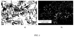
- FIG. 7 is a comparison of the 304 stainless steel forming structure and the consumable rod original structure of this embodiment.
- FIG. 7(a) is the original structure of the 304 stainless steel rod consumable, mainly composed of large pieces of primary austenite, and the grain boundary morphology is mainly flat.
- FIG. 7(b) shows the micro-region semi-solid laser forming structure.
- the primary austenite grains form a specific spherical or pellet shape under intense stirring and friction, and the grain size is finer.
- the bright part between spherocrystals is not a grain boundary in the conventional sense, but an extremely fine liquid phase hardened structure, so that it is almost impossible to distinguish its morphology under an optical microscope.
- Specific embodiment 2 This embodiment differs from specific embodiment 1 in that: the consumable materials are two metal rods with a diameter of 3 mm arranged side by side, and other steps and parameters are the same as those in specific embodiment 1.
- Specific embodiment 3 differs from specific embodiment 1 in that: the heat source is Tig, the angle between the welding gun and the stack layer is 55°, the diameter of the consumable rod is 4 mm, the angle between the consumable rod and the stack layer is 60°, the current is 200 A, the processing speed is 0.3 m/min, the axial thrust of the consumable materials is 100 N, and other steps and parameters are the same as those in specific embodiment 1.
- Specific embodiment 4 differs from specific embodiment 1 in that: the heat source is Mig, the angle between the welding gun and the stack layer is 55°, the angle between the consumable rod and the stack layer is 60°, the current is 300A, the processing speed is 0.4 m/min, the axial thrust of the consumable materials is 100 N, and other steps and parameters are the same as those in specific embodiment 1.
- this embodiment differs from specific embodiment 1 in that: the consumable materials are rectangular strips with a section size of 10 mm x 3 mm, and the self-moving mode of the consumable materials is transverse mechanical reciprocating motion, with the reciprocating frequency of 100 Hz, the amplitude of 0.8 mm, the laser power of 6 KW, and the processing speed of 0.4 m/min.
- Specific embodiment 6 differs from specific embodiment 1 in that: Both the consumable rod and the substrate are 6061 aluminum alloy, the laser power is 6 KW, the moving speed of the consumable materials is 0.4 m/min, and the axial thrust of the consumable materials is 50 N, and during the forming process, 320 mesh SiC reinforced particles are injected into the angle between the consumable materials and the stack layer to prepare particle reinforced aluminum matrix composite materials with a volume fraction of 25% added. Other steps and parameters are the same as in specific embodiment 1.
- SiC reinforced aluminum matrix composite materials prepared by the micro-region semi-solid additive manufacturing method have a full density, the particle and matrix interface are well bonded, the elastic modulus strength is increased by 27%, and the strength is increased by 18%.
Landscapes
- Engineering & Computer Science (AREA)
- Mechanical Engineering (AREA)
- Physics & Mathematics (AREA)
- Optics & Photonics (AREA)
- Plasma & Fusion (AREA)
- Chemical & Material Sciences (AREA)
- Manufacturing & Machinery (AREA)
- Materials Engineering (AREA)
- Powder Metallurgy (AREA)
- Laser Beam Processing (AREA)
Abstract
Description
- The present invention relates to the technical field of metal additive manufacturing, and in particular, to a metal additive manufacturing method with metal semi-solid processing properties.
- In the existing metal additive manufacturing technology, because multiple non-equilibrium thermophysical processes and metallurgical processes cause poor uniformity and stability of the component structure and performance, serious deformation and cracking tendency, and easily generate defects such as pores, shrinkage holes and incomplete fusion, all the problems seriously affect the service performance of additive parts, and also bring great difficulties to the development and promotion of additive manufacturing technologies.
- Usually, the solution to the defects such as pores is post-densification: usually for hot isostatic pressing. The control of the microstructural morphology is solved by heat treatment, and methods such as preheating, heat treatment, optimization process route, compound external fields (such as shot blasting, electromagnetic field, or ultrasound) and the like are used to solve residual stress and workpiece deformation. Although these methods can alleviate the above problems to a certain extent, they require special equipment and additional processes, are inconvenient to operate, and affect processing efficiency, thus even being unable to process some large-sized components or having large expenses. To sum up, these methods alleviate these defects to a certain extent, but they do not fundamentally solve the problems.
- An object of the present invention is to provide an additive manufacturing method for strong external intervention of metal solidification process, and mainly refers to that strong mechanical force is applied to the semi-solid metal coexisting in the solid-liquid two phases during the solidification process, which changes the traditional dendrite growth mode to the equiaxed crystal fine grain growth mode. At the same time, the mechanical force can eliminate the shrinkage and pores of the fused layer to increase the density, and improve the stress distribution state of the formed body to reduce the deformation and cracking tendency of the workpiece.
- The technical solution of the present invention is:
The raw materials (consumable materials) for additive manufacturing are straight rod and strip metal, and heating modes such as high-energy beam, electric arc and resistance heat are applied to the front end region of the consumable material and make it semi-solid state. At the same time, the rotational torsion and the axial thrust applied on the consumables have powerful effects such as shearing, agitation and extrusion, and this process is essentially a mold-free semi-solid rheoforming process. Instead of the mold, the underlying material and the consumable material body are in contact with the semi-solid material, except that the consumables are transited to the underlying material to form a stack layer through the semi-solid forming process. The stacking process is stacked in a set path and lamination to form an entity of a particular size and shape. - 1. A micro-region semi-solid additive manufacturing method, wherein consumable materials are manufactured with rod or strip shaped materials as additives, and are hereinafter referred to as consumables; during operation, a claw drives the consumables to rotate at a speed of 200-10000 rpm and an axial thrust of 10-2000 N is applied to the consumables, and the heat source is used to heat the front end surface of the consumables to a liquid or semi-solid state; in the subsequent cooling and solidification process, the hot metal at the end of these consumables undergoes agitation and extrusion under the action of the axial thrust, rotational torsion and the counter-acting force of substrate or stack layers, to form a mold-free semi-solid rheological processing metal structure; the consumables are uniformly pushed forward at a consumption speed of 0.1-2 m/min and are moved at a speed of 0.1-4 m/min based on a moving path generated by the discrete sections to form continuous stack layers, and the stacking process is repeated to form a molded body; and the heat source comprises a laser beam, an electron beam, a plasma beam, an electric arc, a resistance heat, an induction heating or flame.
- 2. Further, the electric arc is TIG, MIG or CMT.
- 3. Further, the a consumable form is rod or strip shaped materials, and cross-section shape is a solid circle, a hollow circle, a rectangle, or a polygon; one or more consumables are arranged side by side; the length of each consumable is 5-600 cm, and the consumables are used one by one; and the laser spot shape is a circular spot, an elliptical spot, a rectangular spot or a multi-spot.
- 4. Further, The inclination angle of the consumable between the centerline of the consumable and the stack layer is 45°-90°, and the inclination direction is opposite to the moving direction of the consumable; the self-moving mode of the consumable is rotation or plane reciprocating motion; and the laser acts on the front side of the moving direction of the consumable and opposites to the consumable, and the angle of the laser and the stack layer is 5°-60°.
- 5. Further, the upper and lower vibrations are added to the consumables to enhance the forging effect, where the vibration frequency is 1 Hz to 1 kHz, and the vibration amplitude is 0.1-1 mm.
- 6. Further, high energy beam heat sources such as the laser and the electron beam work in a scanning heating mode, and the scanning frequency is 1 Hz to 5 kHz.
- 7. Further, one or several combination external fields of current, magnetic field and ultrasound are simultaneously applied to the consumables to enhance the control effect of metallographic structure and performance.
- 8. Further, in the additive manufacturing process, reinforced composite materials or functionally graded materials are prepared by simultaneously injecting alloy powder having a size of 20 nm to 500 µm, reinforced particles, whiskers or short fibers into a V-shaped opening between the consumable and the stack layer.
- Compared with other metal deposition processes, the present invention has the following advantages and benefits:
The additive manufacturing technology is combined with the semi-solid technology, and the semi-solid rheoforming process is introduced into the additive manufacturing process. After solidification of the metal, a uniform spherical fine-grained structure can be obtained without macrosegregation. The metal solidifies under the action of extrusion and stirring, which can eliminate the defects such as pores, voids, shrinkage and slag inclusion inside the stack layer, and the workpiece can reach full density and improve the stress distribution state of the formed body, so as to reduce the deformation and cracking tendency of the workpiece. - The semi-solid forming metal has a small solidification shrinkage rate, can improve the forming dimensional accuracy, and is easy to achieve near-net forming. During the semi-solid metal forming and processing process, the slurry is always in a controlled and steady state, so that the flowing and splashing of the metal solution hardly occur, and the oxidation and entrapment of the alloy are alleviated. The purity of the material is enhanced, and at the same time, the multi-directional growth can be achieved without providing a special support structure. Compared with powdery consumable materials, the rod and strip materials have obvious advantages such as abundant material types, high material utilization rate, high economic efficiency, and low pollution.
- There is no special restriction on the type of heat source, no complicated equipment is required, and the stress, deformation and structure are well controlled. In most cases, the subsequent processing can be omitted and the process flow can be shortened. Compared with the castings, the semi-solid forming has a low forming temperature, strong controllability in structure and properties; and compared with the forge pieces, it has a small forming resistance and a strong controllability, with mechanical property reaching or exceeding the forging level. Semi-solid additive manufacturing with high energy beam as the heat source can achieve or exceed forgings in both static mechanical properties and fatigue properties.
- The semi-solid material has high viscosity, and the composite material or the gradient functional material can be prepared by synchronous injection or surface preformed alloy powder or reinforcing fiber or ceramic particles during the processing, which can completely solve the macrosegregation and uneven distribution of the reinforced phase.
- The present invention opens up a new method for additive manufacturing and provides a new idea for the development and popularization of semi-solid forming technology.
-
-
FIG. 1 is a schematic diagram showing the principle of a micro-region semi-solid additive manufacturing method by using a laser as a heat source and driving consumables to vibrate up and down; -
FIG. 2 is a local enlargement schematic diagram showing the principle of a micro-region semi-solid additive manufacturing method by using a laser as a heat source; -
FIG. 3 is a schematic diagram showing the principle of a micro-region semi-solid additive manufacturing method by using TIG as a heat source; -
FIG. 4 is a schematic diagram showing the principle of a micro-region semi-solid additive manufacturing method by using MIG as a heat source; -
FIG. 5 is a schematic diagram showing the principle of particle reinforced composites preparing and micro-region semi-solid laser additive manufacturing; -
FIG. 6 is a schematic diagram showing the principle of manufacturing the laser micro-region additive for the lateral reciprocating motion of rectangular consumables; and -
FIG. 7 is a comparison of the microstructure characteristics of semi-solid laser additive manufacturing: a) stainless steel original structure, and b) stainless steel semi-solid laser additive structure. - Specific embodiment 1: the consumable material of this embodiment is 304 stainless steel round rod with a diameter of 5 mm, the substrate is Q235 low carbon steel. The angle between the consumable material rod and the stack layer is 75°, the angle between the laser beam and the stack layer is 15°, the laser power is 4 KW, and the laser focusing spot is rectangular and has a size of 6 mm x 1 mm.
- The specific forming process includes the following steps:
- 1. Establish a 3D model of the metal parts, complete the slicing process by software and generate a machine processing path;
- 2. Remove the oxide film and dirts on the surface of the substrate and consumables;
- 3. Arrange the relative positions of the consumables, the substrate and the laser according to the settings, fasten the substrate, and use the three claws with water-cooling function to catch the consumables;
- 4. Turn on the power to make the three claws to drive the rod-shaped consumables to rotate, with the rotation speed of 800 n/min, and check the coaxiality and roundness deviation of the rotation of the consumables;
- 5. Open the inert gas protection, with the flow rate of argon gas of 30 L/min, and the diameter of the nozzle of 10 mm;
- 6. When the consumable rod rotates, it moves downwardly and squeezes the substrate, and the three claws apply auxiliary upper and lower vibration and axial thrust to the consumables while rotating, with the thrust of 200 N;
- 7. When the laser is turned on, the moving mechanism is started, and the moving mechanism moves at a running speed of 0.6 m/min according to the planned processing path, and the additive manufacturing process is implemented; and
- 8. Repeat the stacking process of
step 7 to finally obtain the stack body, and perform the remaining processing and detection on the stack body. -
FIG. 7 is a comparison of the 304 stainless steel forming structure and the consumable rod original structure of this embodiment.FIG. 7(a) is the original structure of the 304 stainless steel rod consumable, mainly composed of large pieces of primary austenite, and the grain boundary morphology is mainly flat.FIG. 7(b) shows the micro-region semi-solid laser forming structure. The primary austenite grains form a specific spherical or pellet shape under intense stirring and friction, and the grain size is finer. The bright part between spherocrystals is not a grain boundary in the conventional sense, but an extremely fine liquid phase hardened structure, so that it is almost impossible to distinguish its morphology under an optical microscope. - Specific embodiment 2: This embodiment differs from specific embodiment 1 in that: the consumable materials are two metal rods with a diameter of 3 mm arranged side by side, and other steps and parameters are the same as those in specific embodiment 1.
- Specific embodiment 3: as shown in
FIG. 3 , this embodiment differs from specific embodiment 1 in that: the heat source is Tig, the angle between the welding gun and the stack layer is 55°, the diameter of the consumable rod is 4 mm, the angle between the consumable rod and the stack layer is 60°, the current is 200 A, the processing speed is 0.3 m/min, the axial thrust of the consumable materials is 100 N, and other steps and parameters are the same as those in specific embodiment 1. - Specific embodiment 4: as shown in
FIG. 4 , this embodiment differs from specific embodiment 1 in that: the heat source is Mig, the angle between the welding gun and the stack layer is 55°, the angle between the consumable rod and the stack layer is 60°, the current is 300A, the processing speed is 0.4 m/min, the axial thrust of the consumable materials is 100 N, and other steps and parameters are the same as those in specific embodiment 1. - Specific embodiment 5: as shown in
FIG. 6 , this embodiment differs from specific embodiment 1 in that: the consumable materials are rectangular strips with a section size of 10 mm x 3 mm, and the self-moving mode of the consumable materials is transverse mechanical reciprocating motion, with the reciprocating frequency of 100 Hz, the amplitude of 0.8 mm, the laser power of 6 KW, and the processing speed of 0.4 m/min. - Specific embodiment 6: as shown in
FIG. 5 , this embodiment differs from specific embodiment 1 in that: Both the consumable rod and the substrate are 6061 aluminum alloy, the laser power is 6 KW, the moving speed of the consumable materials is 0.4 m/min, and the axial thrust of the consumable materials is 50 N, and during the forming process, 320 mesh SiC reinforced particles are injected into the angle between the consumable materials and the stack layer to prepare particle reinforced aluminum matrix composite materials with a volume fraction of 25% added. Other steps and parameters are the same as in specific embodiment 1. - SiC reinforced aluminum matrix composite materials prepared by the micro-region semi-solid additive manufacturing method have a full density, the particle and matrix interface are well bonded, the elastic modulus strength is increased by 27%, and the strength is increased by 18%.
- The above embodiments are merely further description of the present invention, and specific embodiments of the present invention are not limited to the description. A series of methods derived from simple derivation and modification should be considered as belonging to the scope claimed in the present invention without departing from the concept of the present invention.
Claims (8)
- A micro-region semi-solid additive manufacturing method, wherein consumable materials are manufactured with rod or strip shaped materials as additives, and are hereinafter referred to as consumables; during operation, a claw drives the consumables to rotate at a speed of 200-10000 rpm and an axial thrust of 10-2000 N is applied to the consumables, and the heat source is used to heat the front end surface of the consumables to a liquid or semi-solid state; in the subsequent cooling and solidification process, the hot metal at the end of these consumables undergoes agitation and extrusion under the action of the axial thrust, rotational torsion and the counter-acting force of substrate or stack layers, to form a mold-free semi-solid rheological processing metal structure; the consumables are uniformly pushed forward at a consumption speed of 0.1-2 m/min and are moved at a speed of 0.1-4 m/min based on a moving path generated by the discrete sections to form continuous stack layers, and the stacking process is repeated to form a molded body; and the heat source comprises a laser beam, an electron beam, a plasma beam, an electric arc, a resistance heat, an induction heating or flame.
- The semi-solid additive manufacturing method according to claim 1, wherein the electric arc is TIG, MIG or CMT.
- The semi-solid additive manufacturing method according to claim 1, wherein a consumable form is rod or strip shaped materials, and cross-section shape is a solid circle, a hollow circle, a rectangle, or a polygon; one or more consumables are arranged side by side; the length of each consumable is 5-600 cm, and the consumables are used one by one; and the laser spot shape is a circular spot, an elliptical spot, a rectangular spot or a multi-spot.
- The semi-solid additive manufacturing method according to claim 1, wherein an inclination angle of the consumable between the centerline of the consumable and the stack layer is 45°-90°, and the inclination direction is opposite to the moving direction of the consumable; the self-moving mode of the consumable is rotation or plane reciprocating motion; and the laser acts on the front side of the moving direction of the consumable and opposites to the consumable, and the angle of the laser and the stack layer is 5°-60°.
- The semi-solid additive manufacturing method according to claim 1, wherein the upper and lower vibrations are added to the consumables to enhance the forging effect, wherein the vibration frequency is 1 Hz to 1 kHz, and the vibration amplitude is 0.1-1 mm.
- The semi-solid additive manufacturing method according to claim 1, wherein high energy beam heat sources such as the laser and the electron beam work in a scanning heating mode, and the scanning frequency is 1 Hz to 5 kHz.
- The semi-solid additive manufacturing method according to claim 1, wherein one or several combination external fields of current, magnetic field and ultrasound are simultaneously applied to the consumables to enhance the control effect of metallographic structure and performance.
- The semi-solid additive manufacturing method according to claim 1, wherein in the additive manufacturing process, reinforced composite materials or functionally graded materials are prepared by simultaneously injecting alloy powder having a size of 20 nm to 500 µm, reinforced particles, whiskers or short fibers into a V-shaped opening between the consumable and the stack layer.
Applications Claiming Priority (2)
| Application Number | Priority Date | Filing Date | Title |
|---|---|---|---|
| CN201710564464.9A CN107414325B (en) | 2017-07-12 | 2017-07-12 | Micro-area semi-solid additive manufacturing method |
| PCT/CN2018/093506 WO2019011132A1 (en) | 2017-07-12 | 2018-06-29 | Micro-region semi-solid additive manufacturing method |
Publications (2)
| Publication Number | Publication Date |
|---|---|
| EP3639964A1 true EP3639964A1 (en) | 2020-04-22 |
| EP3639964A4 EP3639964A4 (en) | 2020-07-01 |
Family
ID=60427563
Family Applications (1)
| Application Number | Title | Priority Date | Filing Date |
|---|---|---|---|
| EP18831523.8A Withdrawn EP3639964A4 (en) | 2017-07-12 | 2018-06-29 | METHOD FOR THE GENERATIVE PRODUCTION OF A SEMI-SOLID BODY IN THE MICROREGION |
Country Status (4)
| Country | Link |
|---|---|
| US (1) | US11364570B2 (en) |
| EP (1) | EP3639964A4 (en) |
| CN (1) | CN107414325B (en) |
| WO (1) | WO2019011132A1 (en) |
Families Citing this family (28)
| Publication number | Priority date | Publication date | Assignee | Title |
|---|---|---|---|---|
| CN107414325B (en) | 2017-07-12 | 2020-01-03 | 北京工业大学 | Micro-area semi-solid additive manufacturing method |
| US10928627B2 (en) * | 2017-11-22 | 2021-02-23 | Magic Leap, Inc. | Thermally actuated cantilevered beam optical scanner |
| CN110026649B (en) | 2018-01-12 | 2022-03-08 | 通用电气公司 | Temperature control system and method for additive manufacturing |
| CN108296665A (en) * | 2018-01-26 | 2018-07-20 | 哈尔滨工业大学(威海) | A kind of nano particle insertion type seam organization method of modifying, device and welding wire |
| US11229977B2 (en) * | 2018-07-19 | 2022-01-25 | Lincoln Global, Inc. | Laser hot wire additive deposition head with omni-directional build path |
| CN109128681A (en) * | 2018-09-26 | 2019-01-04 | 刘军发 | A kind of electrode induction melting increasing material manufacturing apparatus and method for |
| CN111112801A (en) * | 2019-12-20 | 2020-05-08 | 威海东海船舶修造有限公司 | A kind of graphene intervention welding method |
| CN111055001A (en) * | 2020-01-03 | 2020-04-24 | 无锡市产品质量监督检验院 | Cement roller press surface additive manufacturing repair device and repair method thereof |
| CN111408721A (en) * | 2020-04-03 | 2020-07-14 | 北京机科国创轻量化科学研究院有限公司 | A kind of aluminum alloy semi-solid melting three-dimensional direct writing forming method |
| CN112222575B (en) * | 2020-09-03 | 2021-12-07 | 江苏科技大学 | Sliding bearing bush material and preparation method thereof |
| CN112139656A (en) * | 2020-09-30 | 2020-12-29 | 中国兵器工业第五九研究所 | Current-assisted friction additive manufacturing device and method |
| US20220097170A1 (en) * | 2020-09-30 | 2022-03-31 | No. 59 Institute Of China Ordnance Industry | Current auxillary friction additive manufacturing device and method |
| CN114951701B (en) * | 2021-02-19 | 2025-10-17 | 空客(北京)工程技术中心有限公司 | Additive manufacturing system, additive manufacturing method, and computer readable medium |
| CN113020754B (en) * | 2021-03-31 | 2022-09-16 | 沈阳大学 | A 5556 aluminum alloy cold metal transition (CMT) arc additive manufacturing process |
| CN113231652A (en) * | 2021-05-07 | 2021-08-10 | 上海理工大学 | Near-net forming device for semisolid metal fuse wire additive manufacturing and printing method |
| CN113102862B (en) * | 2021-05-13 | 2023-06-16 | 重庆大学 | Ultrasonic-assisted arc additive manufacturing method |
| EP4101574B1 (en) * | 2021-06-10 | 2024-07-03 | Laser Zentrum Hannover e.V. | Device for electrical resistance deposition, in particular resistance welding or resistance soldering, method for applying an additional material by means of respective laser beams and use of a device |
| CN113601103B (en) * | 2021-06-25 | 2022-10-14 | 上海航天精密机械研究所 | Method for repairing loose defect of aluminum and magnesium alloy casting |
| CN115781023B (en) * | 2021-09-10 | 2025-08-22 | 武汉大学 | A dual-melting pool additive manufacturing method for heterogeneous materials based on thermal regulation |
| DE102022112950A1 (en) | 2022-05-23 | 2023-11-23 | Laser Zentrum Hannover E.V. | Method and device for applying a strand-shaped welding filler material |
| CN115156523B (en) * | 2022-07-29 | 2023-09-26 | 大连理工大学 | A friction stir additive manufacturing device that can prepare nanoparticle-reinforced metal matrix composite materials |
| CN115464114B (en) * | 2022-08-19 | 2024-08-20 | 昆明理工大学 | A thixotropic rotation extrusion method and device for axle sleeve parts |
| CN115870589B (en) * | 2022-11-11 | 2023-09-05 | 天津大学 | Automatic build-up welding method for CMT (cell line) of side wall opening of bimetal composite pipe |
| CN116060737B (en) * | 2023-01-17 | 2023-09-05 | 天津大学 | An automatic welding method for saddle line welding seam of saddle-type T-joint |
| CN117020459A (en) * | 2023-08-21 | 2023-11-10 | 上海工程技术大学 | A welding method and device for laser-CMT, TIG and multiple heat sources to weld aluminum alloys |
| CN119387800B (en) * | 2024-09-13 | 2026-04-10 | 哈尔滨工业大学 | Additive component, friction stir deposition additive manufacturing apparatus and method |
| CN119525684A (en) * | 2024-11-18 | 2025-02-28 | 南方科技大学 | Rotational vibration assisted friction stir additive manufacturing forming device and forming method |
| CN119609292B (en) * | 2024-11-29 | 2025-11-18 | 上海航天设备制造总厂有限公司 | Method and system for forming thin rod structures by electric arc wire additive manufacturing |
Family Cites Families (21)
| Publication number | Priority date | Publication date | Assignee | Title |
|---|---|---|---|---|
| US6299050B1 (en) * | 2000-02-24 | 2001-10-09 | Hitachi, Ltd. | Friction stir welding apparatus and method |
| US7164094B2 (en) * | 2004-01-12 | 2007-01-16 | General Electric Company | Apparatus and method for electrofriction welding |
| DE102005029881A1 (en) * | 2005-06-27 | 2006-12-28 | Gkss-Forschungszentrum Geesthacht Gmbh | Friction stir welding apparatus includes pin to form plasticized zone, first friction surface segment having first friction surface for resting on the workpiece, and feed device for introducing filler material into the plasticized zone |
| US10092975B2 (en) * | 2008-02-12 | 2018-10-09 | United Technologies Corporation | Solid state additive manufacturing system |
| CN101537529B (en) * | 2009-04-24 | 2011-03-30 | 重庆大学 | Pin tool for friction stir welding and ultrafine grain preparation method thereof |
| WO2014130190A1 (en) * | 2013-01-22 | 2014-08-28 | University Of Utah Research Foundation | Friction spot welding and friction seam welding |
| CN103121145B (en) * | 2013-02-07 | 2015-08-26 | 沈阳航空航天大学 | A kind of method preparing Ultra-fine Grained/nanocrystalline sheet material based on ultrasonic wave added Semi-solid Stirring friction processing technology |
| US10562132B2 (en) * | 2013-04-29 | 2020-02-18 | Nuburu, Inc. | Applications, methods and systems for materials processing with visible raman laser |
| WO2015020954A1 (en) * | 2013-08-09 | 2015-02-12 | United Technologies Corporation | Method for integrating multiple materials in a foil consolidation of additive manufacturing process |
| US9358635B2 (en) * | 2013-12-19 | 2016-06-07 | Siemens Energy, Inc. | Rastered laser melting of a curved surface path with uniform power density distribution |
| CN103753029B (en) * | 2013-12-23 | 2016-01-20 | 江苏烁石焊接科技有限公司 | Electric arc metallic stud welding method under a kind of frictional cleaning homogenizing and device |
| ES2856399T3 (en) * | 2014-08-20 | 2021-09-27 | Etxetar Sa | Method and system for additive manufacturing using a light beam |
| CN104404509B (en) * | 2014-11-28 | 2017-06-16 | 中南大学 | A kind of metal laser melting increasing material manufacturing method |
| CN105171229A (en) * | 2015-09-25 | 2015-12-23 | 北京理工大学 | Friction stir additive manufacturing method for metal materials |
| CN105397276B (en) * | 2015-12-15 | 2017-11-03 | 哈尔滨工业大学 | A kind of method of agitating friction weldering increasing material manufacturing bar |
| CN205927497U (en) * | 2016-08-16 | 2017-02-08 | 东晓 | 3D (three -dimensional) printing device |
| CN106112254B (en) * | 2016-08-16 | 2018-08-10 | 东晓 | A kind of 3D printing device and method |
| US10688588B2 (en) * | 2017-06-12 | 2020-06-23 | Raytheon Technologies Corporation | Continuous feed spindle attachment |
| CN107414325B (en) * | 2017-07-12 | 2020-01-03 | 北京工业大学 | Micro-area semi-solid additive manufacturing method |
| CN107598358B (en) * | 2017-10-27 | 2020-01-03 | 合肥工业大学 | Additive manufacturing method through consumption type friction stir tool |
| CN108372658A (en) * | 2018-02-07 | 2018-08-07 | 华中科技大学 | The selective melting manufacturing process and equipment of continuous fiber reinforced composite materials and part |
-
2017
- 2017-07-12 CN CN201710564464.9A patent/CN107414325B/en active Active
-
2018
- 2018-06-29 EP EP18831523.8A patent/EP3639964A4/en not_active Withdrawn
- 2018-06-29 WO PCT/CN2018/093506 patent/WO2019011132A1/en not_active Ceased
-
2020
- 2020-01-13 US US16/740,780 patent/US11364570B2/en active Active
Also Published As
| Publication number | Publication date |
|---|---|
| WO2019011132A1 (en) | 2019-01-17 |
| CN107414325B (en) | 2020-01-03 |
| CN107414325A (en) | 2017-12-01 |
| US11364570B2 (en) | 2022-06-21 |
| EP3639964A4 (en) | 2020-07-01 |
| US20200147726A1 (en) | 2020-05-14 |
Similar Documents
| Publication | Publication Date | Title |
|---|---|---|
| US11364570B2 (en) | Micro-region semi-solid additive manufacturing method | |
| Li et al. | Microstructure and property of Ni/WC/La2O3 coatings by ultrasonic vibration-assisted laser cladding treatment | |
| CN109807558B (en) | A kind of wire arc additive manufacturing method of titanium alloy | |
| WO2020156224A1 (en) | Wire and arc additive manufacturing method for magnesium alloy | |
| CN106757001B (en) | A method and device for laser cladding assisted by electromagnetic stirring in a forced cooling environment | |
| CN108213649A (en) | A kind of magnetic field control type electric arc robot increases material manufacturing process and device | |
| Xu et al. | Effects of magnetic fields in arc welding, laser welding, and resistance spot welding: a review | |
| CN107283059B (en) | A kind of molten laser-impact that accumulates of electric arc forges increasing material manufacturing method and apparatus | |
| CN103305828A (en) | Device for strengthening laser cladding layer by ultrasonic impact and method thereof | |
| CN104404509A (en) | Metal laser melting additive manufacturing method | |
| CN102240860A (en) | Method and equipment for manufacturing gradient material mould | |
| CN106591824A (en) | Manufacturing machine and method of titanium alloy parts | |
| CN102719823A (en) | Method for improving microstructure of laser remelting composite coating through vibration | |
| CN205869704U (en) | Electromagnetic oscillation assists friction stir welding device | |
| CN102179637B (en) | Manufacturing method and equipment of unequal-section bimetal transmission part | |
| CN111515399A (en) | A kind of ceramic particle reinforced metal matrix composite material fusion deposition additive manufacturing method | |
| Zhang et al. | Welding characteristics of AZ31B magnesium alloy using DC-PMIG welding | |
| CN103612019A (en) | A CO2 Laser-TIG Arc Hybrid Welding Method Using Magnetic Stirring | |
| CN117884657A (en) | An external field assisted laser additive manufacturing device and a method of using the same | |
| CN111172404A (en) | A kind of electron beam remelting device and method for particle reinforced aluminum matrix composite material | |
| Miao et al. | Magnetic controlled arc welding technology: a review | |
| CN102703750A (en) | Method for preparing particle reinforced gradient material by combined action of ultrasonic and travelling wave magnetic fields | |
| CN105689711B (en) | Electromagnetic Stirring Assisted Laser Rapid Forming of Nickel-based Alloy Parts | |
| CN114951689A (en) | A kind of preparation method of marine titanium alloy gradient composite material based on arc additive | |
| US9475120B1 (en) | Apparatus and method for dispersing particles in a molten material without using a mold |
Legal Events
| Date | Code | Title | Description |
|---|---|---|---|
| STAA | Information on the status of an ep patent application or granted ep patent |
Free format text: STATUS: THE INTERNATIONAL PUBLICATION HAS BEEN MADE |
|
| PUAI | Public reference made under article 153(3) epc to a published international application that has entered the european phase |
Free format text: ORIGINAL CODE: 0009012 |
|
| STAA | Information on the status of an ep patent application or granted ep patent |
Free format text: STATUS: REQUEST FOR EXAMINATION WAS MADE |
|
| 17P | Request for examination filed |
Effective date: 20200113 |
|
| AK | Designated contracting states |
Kind code of ref document: A1 Designated state(s): AL AT BE BG CH CY CZ DE DK EE ES FI FR GB GR HR HU IE IS IT LI LT LU LV MC MK MT NL NO PL PT RO RS SE SI SK SM TR |
|
| AX | Request for extension of the european patent |
Extension state: BA ME |
|
| A4 | Supplementary search report drawn up and despatched |
Effective date: 20200602 |
|
| RIC1 | Information provided on ipc code assigned before grant |
Ipc: B23K 28/00 20060101ALI20200526BHEP Ipc: B23K 26/342 20140101ALI20200526BHEP Ipc: B23K 9/04 20060101ALI20200526BHEP Ipc: B23K 11/00 20060101ALI20200526BHEP Ipc: B23K 3/06 20060101ALI20200526BHEP Ipc: B23K 15/00 20060101ALI20200526BHEP Ipc: B23K 10/02 20060101ALI20200526BHEP Ipc: B23K 20/12 20060101AFI20200526BHEP Ipc: B23K 26/34 20140101ALI20200526BHEP |
|
| DAV | Request for validation of the european patent (deleted) | ||
| DAX | Request for extension of the european patent (deleted) | ||
| STAA | Information on the status of an ep patent application or granted ep patent |
Free format text: STATUS: EXAMINATION IS IN PROGRESS |
|
| 17Q | First examination report despatched |
Effective date: 20230424 |
|
| P01 | Opt-out of the competence of the unified patent court (upc) registered |
Effective date: 20230526 |
|
| STAA | Information on the status of an ep patent application or granted ep patent |
Free format text: STATUS: THE APPLICATION IS DEEMED TO BE WITHDRAWN |
|
| 18D | Application deemed to be withdrawn |
Effective date: 20250103 |