EP3639963B1 - Device and method for operating a resistance welding device - Google Patents
Device and method for operating a resistance welding device Download PDFInfo
- Publication number
- EP3639963B1 EP3639963B1 EP19193526.1A EP19193526A EP3639963B1 EP 3639963 B1 EP3639963 B1 EP 3639963B1 EP 19193526 A EP19193526 A EP 19193526A EP 3639963 B1 EP3639963 B1 EP 3639963B1
- Authority
- EP
- European Patent Office
- Prior art keywords
- regulator
- welding
- current
- controller
- data set
- Prior art date
- Legal status (The legal status is an assumption and is not a legal conclusion. Google has not performed a legal analysis and makes no representation as to the accuracy of the status listed.)
- Active
Links
- 238000003466 welding Methods 0.000 title claims description 250
- 238000000034 method Methods 0.000 title claims description 118
- 230000008569 process Effects 0.000 claims description 88
- 238000012937 correction Methods 0.000 claims description 33
- 229910052751 metal Inorganic materials 0.000 claims description 26
- 239000002184 metal Substances 0.000 claims description 26
- 230000001105 regulatory effect Effects 0.000 claims description 10
- 238000003860 storage Methods 0.000 claims description 7
- 230000001276 controlling effect Effects 0.000 claims description 5
- 230000002123 temporal effect Effects 0.000 claims 15
- 238000004590 computer program Methods 0.000 claims 2
- 238000001514 detection method Methods 0.000 description 11
- 239000000463 material Substances 0.000 description 11
- 238000004891 communication Methods 0.000 description 8
- 238000004886 process control Methods 0.000 description 6
- 230000007704 transition Effects 0.000 description 6
- 238000004519 manufacturing process Methods 0.000 description 5
- 230000003044 adaptive effect Effects 0.000 description 4
- 238000010276 construction Methods 0.000 description 4
- 238000005259 measurement Methods 0.000 description 4
- 229910001335 Galvanized steel Inorganic materials 0.000 description 3
- 229910052782 aluminium Inorganic materials 0.000 description 3
- XAGFODPZIPBFFR-UHFFFAOYSA-N aluminium Chemical compound [Al] XAGFODPZIPBFFR-UHFFFAOYSA-N 0.000 description 3
- 230000005540 biological transmission Effects 0.000 description 3
- 239000008397 galvanized steel Substances 0.000 description 3
- 239000000155 melt Substances 0.000 description 3
- 238000006243 chemical reaction Methods 0.000 description 2
- 238000000576 coating method Methods 0.000 description 2
- 238000001816 cooling Methods 0.000 description 2
- 239000007769 metal material Substances 0.000 description 2
- 230000000630 rising effect Effects 0.000 description 2
- 229910000838 Al alloy Inorganic materials 0.000 description 1
- 229910000831 Steel Inorganic materials 0.000 description 1
- 238000007792 addition Methods 0.000 description 1
- 230000003321 amplification Effects 0.000 description 1
- 230000008859 change Effects 0.000 description 1
- 230000001419 dependent effect Effects 0.000 description 1
- 238000010586 diagram Methods 0.000 description 1
- 238000009826 distribution Methods 0.000 description 1
- 239000002655 kraft paper Substances 0.000 description 1
- 238000013507 mapping Methods 0.000 description 1
- 150000002739 metals Chemical class 0.000 description 1
- 238000003199 nucleic acid amplification method Methods 0.000 description 1
- 238000012545 processing Methods 0.000 description 1
- 230000002787 reinforcement Effects 0.000 description 1
- 230000004043 responsiveness Effects 0.000 description 1
- 239000010959 steel Substances 0.000 description 1
Images


Classifications
-
- B—PERFORMING OPERATIONS; TRANSPORTING
- B23—MACHINE TOOLS; METAL-WORKING NOT OTHERWISE PROVIDED FOR
- B23K—SOLDERING OR UNSOLDERING; WELDING; CLADDING OR PLATING BY SOLDERING OR WELDING; CUTTING BY APPLYING HEAT LOCALLY, e.g. FLAME CUTTING; WORKING BY LASER BEAM
- B23K11/00—Resistance welding; Severing by resistance heating
- B23K11/24—Electric supply or control circuits therefor
- B23K11/25—Monitoring devices
- B23K11/252—Monitoring devices using digital means
- B23K11/257—Monitoring devices using digital means the measured parameter being an electrical current
-
- B—PERFORMING OPERATIONS; TRANSPORTING
- B23—MACHINE TOOLS; METAL-WORKING NOT OTHERWISE PROVIDED FOR
- B23K—SOLDERING OR UNSOLDERING; WELDING; CLADDING OR PLATING BY SOLDERING OR WELDING; CUTTING BY APPLYING HEAT LOCALLY, e.g. FLAME CUTTING; WORKING BY LASER BEAM
- B23K11/00—Resistance welding; Severing by resistance heating
- B23K11/10—Spot welding; Stitch welding
- B23K11/11—Spot welding
- B23K11/115—Spot welding by means of two electrodes placed opposite one another on both sides of the welded parts
-
- B—PERFORMING OPERATIONS; TRANSPORTING
- B23—MACHINE TOOLS; METAL-WORKING NOT OTHERWISE PROVIDED FOR
- B23K—SOLDERING OR UNSOLDERING; WELDING; CLADDING OR PLATING BY SOLDERING OR WELDING; CUTTING BY APPLYING HEAT LOCALLY, e.g. FLAME CUTTING; WORKING BY LASER BEAM
- B23K11/00—Resistance welding; Severing by resistance heating
- B23K11/24—Electric supply or control circuits therefor
-
- B—PERFORMING OPERATIONS; TRANSPORTING
- B23—MACHINE TOOLS; METAL-WORKING NOT OTHERWISE PROVIDED FOR
- B23K—SOLDERING OR UNSOLDERING; WELDING; CLADDING OR PLATING BY SOLDERING OR WELDING; CUTTING BY APPLYING HEAT LOCALLY, e.g. FLAME CUTTING; WORKING BY LASER BEAM
- B23K11/00—Resistance welding; Severing by resistance heating
- B23K11/10—Spot welding; Stitch welding
- B23K11/11—Spot welding
-
- B—PERFORMING OPERATIONS; TRANSPORTING
- B23—MACHINE TOOLS; METAL-WORKING NOT OTHERWISE PROVIDED FOR
- B23K—SOLDERING OR UNSOLDERING; WELDING; CLADDING OR PLATING BY SOLDERING OR WELDING; CUTTING BY APPLYING HEAT LOCALLY, e.g. FLAME CUTTING; WORKING BY LASER BEAM
- B23K11/00—Resistance welding; Severing by resistance heating
- B23K11/36—Auxiliary equipment
-
- B—PERFORMING OPERATIONS; TRANSPORTING
- B23—MACHINE TOOLS; METAL-WORKING NOT OTHERWISE PROVIDED FOR
- B23K—SOLDERING OR UNSOLDERING; WELDING; CLADDING OR PLATING BY SOLDERING OR WELDING; CUTTING BY APPLYING HEAT LOCALLY, e.g. FLAME CUTTING; WORKING BY LASER BEAM
- B23K2101/00—Articles made by soldering, welding or cutting
- B23K2101/006—Vehicles
-
- B—PERFORMING OPERATIONS; TRANSPORTING
- B23—MACHINE TOOLS; METAL-WORKING NOT OTHERWISE PROVIDED FOR
- B23K—SOLDERING OR UNSOLDERING; WELDING; CLADDING OR PLATING BY SOLDERING OR WELDING; CUTTING BY APPLYING HEAT LOCALLY, e.g. FLAME CUTTING; WORKING BY LASER BEAM
- B23K2101/00—Articles made by soldering, welding or cutting
- B23K2101/18—Sheet panels
Definitions
- the present invention relates to a resistance welding device, a database for a resistance welding device and a method for operating a resistance welding device, as well as a data record for use with a welding controller.
- Resistance welding is usually used to create a connection between two sheets of metal or metal parts.
- a resistance welding device has two welding electrodes between which a welding current flows. Currents of 5 kA to a few 50 kA with welding voltages in the range of 1 to 2.5 V are usually used for welding.
- the parts to be connected can be sheets of the same type or sheets of different metal types and thicknesses.
- the individual welding processes take place in time windows of up to one second. However, longer times are also possible. For example, in the course of automated body shell construction, different workpieces, e.g. sheets, are welded together using robot-guided welding tools using resistance welding.
- ASR adaptive welding control
- the process impedance is made up of material resistance and contact resistance.
- the material resistances depend on the material and the condition of the welding electrodes, as well as on the two welding materials.
- the contact resistances result from the welding process itself, i.e. in particular from the surfaces that come into contact, the resulting weld lens or weld seam and the impedance of the welding electrodes.
- the target impedances stored in the welding control or externally are referred to below as reference curves.
- the ASR uses the difference between the reference curve and a measurement curve for the current weld and adjusts the welding current and the welding time, i.e. the setpoint curve for a current controller, accordingly.
- KSR constant current control
- resistance welding is used to weld different workpieces, such as metal sheets, together in automated body construction.
- the problem here is that several vehicle models with different model variants are manufactured on one production line and with one welding control. Depending on how the vehicle models arrive on this line, a wide variety of sheet metal combinations are welded. The order of the vehicles changes constantly. At the same time, the variance of the sheet metal combinations to be welded increases. The coatings on the sheets are also becoming more and more different and the necessary control of the resistance welding device differs significantly for different coatings.
- welding points e.g. approx. 5,000 welding points for a mid-range vehicle
- workpiece thicknesses and/or material combinations e.g. approx. 700 combinations for a mid-range vehicle.
- Welding controls therefore receive process control parameters - i.e. target values or target curves - to control the welding process of the points to be welded, depending on the workpiece thickness and/or material combinations of the respective welding point.
- process control parameters - i.e. target values or target curves - to control the welding process of the points to be welded, depending on the workpiece thickness and/or material combinations of the respective welding point.
- the workpiece material and/or workpiece thicknesses will be discussed material combination, the term sheet metal/thickness combination or the abbreviation BDK is used.
- a data set for a weld joint includes a position on the workpiece and a sheet metal/thickness combination (BDK).
- An additional data set is assigned to this sheet metal/thickness combination, regardless of the position on the workpiece.
- This additional data set includes process control parameters such as a current setpoint curve, a force or torque profile, a reference curve and possibly other reference curves.
- a database is created in which production data is sorted according to the same BDK.
- a specific data set is created for each identical BDK.
- the BDK-specific data includes process control parameters (such as welding current, current time, electrode force and/or reference curves).
- JP S47 37828 U discloses a welding apparatus in which a turns ratio of a welding transformer is adjusted for each welding position depending on the two types of metals to be welded.
- the publication DE 93 170 13 U1 discloses a welding tool for spot welding with multi-axis manipulators, consisting of an electrode holder connected to the manipulator hand with a welding electrode, the welding electrode being mounted in the electrode holder in a longitudinally movable and resilient manner, so that the welding electrode is less stressed and better protected by vibrations and force peaks.
- the registration JP 20120 954 42 A discloses changing the proportional gain, the reset time and the lead time of the PID control based on a determination of inductance coefficients which correspond to the inductance value of the DC choke in order to accelerate the responsiveness of the PID control during a welding process.
- the font US 5,552,575 discloses how performance of the welding tool, which moves rapidly on a dynamically planned trajectory, is modulated in real time to achieve controlled heat input distribution in the weld area and on the weld centerline, resulting in improved tensile strength of the joint.
- the font DE 692 07 735 T2 relates to the field of control systems for shifting vehicle systems and discloses a transmission control system with different system parameters, for example proportional, integral and differential gains, some of which are changed according to the previous behavior of the servomechanism when shifting the transmission.
- the patent application EP 2 246 760 A2 discloses a method for determining at least one controller parameter of a control element in a web tension control circuit for a processing machine, wherein at least one controller parameter is determined as a function of at least one parameter characterizing the web and at least one dead time.
- the patent application WO 20066006042 572 A1 which forms the basis for the preamble of claim 1, relates to a device for carrying out a welding process with sensor means for sensing the position and / or changes in position of a welding head relative to a reference position of the welding head and / or to the workpieces to be welded, so that at least a parameter of the shitting process can be influenced depending on the perceived position and/or change in position and is viewed as the closest state of the art.
- a welding control and a method for controlling a welding process are to be provided, in which during welding a welding tool for welding connections that were previously considered difficult, achieving a more consistent welding quality.
- a resistance welding device with a welding control for controlling a welding tool according to claim 1.
- the task is also solved by a database for a resistance welding device according to claim 10, a method for operating a resistance device according to claim 15, and a data set with the features of claim 20.
- the invention is based on the finding that by setting the parameters of the welding control controllers specifically for the welding point, the welding quality and the repeatability of a weld can be significantly improved, among other things in the case of difficult welded connections.
- a process control parameter such as a current setpoint or a reference curve
- a controller parameter such as the gain of the proportional component K P or the reset time T N of the integral component of a PI controller.
- a current regulator of the welding control regulates a predetermined welding current for welding a point.
- the setpoint is taken from a data set in a storage device of the welding control or an external database and fed to the current controller as a time setpoint curve by a special device in the welding control.
- This welding control device is referred to here as an allocation device.
- a parameterization device is added to the assignment device. If the data set is supplemented with the said parameters for the current controller, the parameterization device can optimally adapt the parameters - i.e. the controller parameters - of the current controller to the BDK to be welded. The welding process can be further improved.
- the parameters for the current regulator can be adjusted very efficiently using the allocation device that is already present in a welding control. To do this, the data in the data set for the BDK of the connection to be welded only needs to be supplemented with special controller parameters for the current controller.
- the controller parameters proportional gain K P and/or the reset time T N can be optimally adapted to the specific BDK in a simple manner. This makes it easy and very efficient to find the optimal setting and parameterization of the current controller for each sheet metal/thickness combination to be welded to be carried out. The production plant's rejects due to faulty welded connections are reduced. Furthermore, improved control of the welding process is made possible without the need for additional hardware, in particular without additional sensors.
- Correction parameters mean the controller parameters of the process controller.
- the data in the data set for the BDK of the connection to be welded is supplemented by data that specify one or more correction parameters of the process controller individually for this specific BDK.
- an adjustment of the welding current and welding time can be controlled as a reaction of the process controller to a deviation of a recorded quantity - such as current - and the corresponding reference curve.
- the welding process control and its parameterization are therefore carried out depending on the BDK to be welded and not exclusively on a comparison of the actual and reference curve. This allows the welding process to be significantly improved.
- the correction parameters of the process controller such as the gain, i.e. how much the current is adjusted in the event of a process deviation, and/or the gain of the current time extension, i.e. how much the duration of the current flow is adjusted in the event of a process deviation, and/or to adapt the limit of the current adjustment, but also other correction parameters of the process controller not explicitly mentioned here, to the specific BDK.
- the welding of sheet metal combinations made of galvanized steel requires a much smaller intervention by the process controller regarding the welding current and the welding time than the welding of sheet metal combinations made of ungalvanized steel sheets.
- the process controller can specify higher currents with longer durations as setpoints to the current controller.
- the diameter of the welding points on galvanized steel sheets is also smaller than on non-galvanized ones Sheet metal, which leads to increased wear on the welding electrodes.
- the higher energy input as well as the smaller tolerance band and the higher wear of the electrodes require a higher power source and an exact adjustment of the control parameters for dynamic control. This can also reduce the thermal and mechanical stress on the electrodes, for example.
- the parameterization device of the welding control sets the optimal correction parameters of the process controller for each welding process specifically for the sheet metal/thickness combination currently being welded.
- the basis for this procedure is knowledge stored in the database regarding the necessary welding process in relation to the correction parameters of the process controller.
- the database or a data record stored therein provides a structure, for example in the form of tables or fields provided for recording values, in which the said knowledge is stored in the form of correction parameters - in particular adapted for the respective BDK.
- welding spatter can be prevented by adapting the parameters of the process controller to the BDK.
- Newer or high-quality welding controls include a drive controller, in particular a force/torque controller for the welding tool, for example for the closing drive of a welding gun.
- a drive controller in particular a force/torque controller for the welding tool, for example for the closing drive of a welding gun.
- the force/torque controller can be specifically adapted to the BDK to be welded. By better dosing the contact pressure, deformation of the welding tool is counteracted and the welding electrodes can be positioned precisely. The welding process is further improved.
- the parameters gain K P and/or reset time T N of the force/torque controller but also other parameters of the force/torque controller not explicitly mentioned here, can be optimally adapted to the specific BDK in a simple manner.
- Edge welds are particularly problematic. With such an edge weld, the electrodes slowly “slide” down to the side of the workpiece as they melt. This results in a continuous loss of strength. The electrode drive constantly adjusts the force; overshoots occur during the control. If you provide BDK specifically created for edge welds and corresponding data sets for these BDK, the control parameters of the force or torque controller can be advantageously and efficiently adapted to these difficult welding processes. It is particularly conceivable to include the position of the welding point on the workpiece in the parameter selection for the force/torque controller to include. This can improve the quality of the welding process for edge welds.
- the resistance welding device 1 includes a welding controller 10 and a welding robot 20.
- the welding control 10 comprises a converter 100, a storage device 110, a detection device 120, an allocation device 130 with a parameterization device 140, a current controller 150 and a process controller 160, a force/torque controller 170 and a communication device 180.
- the welding robot 20 carries a welding tool 200, which serves to materially join the welded connection to the sheets 250 to be connected, for example a car body, by means of a current flow.
- the welding tool 200 includes two welding electrodes 210 with electrode caps, not shown here.
- the welding tool 200 is designed as a C-welding gun, but can also be an X-gun or another welding tool.
- the welding robot 20 includes a welding transformer 220, a measuring device 230 and a communication device 240. With the measuring device 230, the current flow through the welding electrodes 210, the voltage at the welding electrodes 210, the force that the welding electrodes 210 exert on the sheets 250 and / or the position of the welding electrodes 210 is measured.
- the communication device 240 With the communication device 240, the data from the measuring device 230 is transmitted to the detection device 120 of the welding control 10 via the communication device 180.
- the transmission can be analogue or digital, for example via a fieldbus or wirelessly.
- the inverter 100 of the welding controller 10 converts the three-phase mains voltage from the mains frequency into a voltage of a medium frequency, which feeds the welding transformer 220 of the welding robot 20.
- the welding transformer 220 provides the welding current that flows through the sheets 250 to be connected via the welding electrodes 210 and via the electrode caps (not shown) and serves as a rectifier and a controllable power source.
- the level of the welding current is regulated by the current regulator 150 of the welding control 10, which in turn controls the converter 100.
- a setpoint curve serves as the setpoint for the current regulator 150 of the welding control 10.
- the allocation device 130 reads a list of the points to be welded from a data record in the storage device 110 or from an external database (not shown).
- the assignment device 130 then reads a data set for the BDK of the current point to be welded from the list of points to be welded by referencing.
- the data record read out for the BDK includes a data field for the setpoint curve for the current controller 150.
- the setpoint curve for the current controller 150 is, for example, composed of segments of constant current curve, which are connected by linearly rising or falling transition segments and is determined by the level of the currents with a constant curve and described by the slopes of the transition segments.
- the setpoint curve for the current curve can also be composed of value pairs consisting of time values and current values which are linearly interpolated by an additional interpolator, not shown, or of any combination of linear segments with transition segments and value pairs of time and current values.
- the setpoint curve for the current controller 150 is retrieved from the allocation device 130 and supplied to the process controller 160 at its upper input as a current setpoint curve during the welding process. In the non-adaptive operating mode KSR of the process controller 160, this setpoint curve is passed on unchanged to the current controller 150.
- the manipulated variable of the process controller 160 therefore serves the current controller 150 as a time course of the current setpoint.
- the manipulated variable of the current controller 150 is a signal, in particular a pulse width modulated signal, which is supplied to the converter 100.
- the inverter 100 controls the welding transformer 220 with an alternating current on its primary side. On the secondary side, the welding transformer 220 is connected to the welding gun or the welding tool 200 on the welding robot 20.
- the measuring device 230 of the welding robot 20 measures the electrical current that flows through the welding electrodes 210 of the welding tool 200 and transmits these values to the detection device 120 via the communication devices 180 and 240.
- the actual value for the current regulator 150 is supplied to the current regulator 150 by the detection device 120 .
- the current controller 150 has controller parameters such as a gain K P adapted to the welding transformer 220 and/or a reset time T N .
- the data set read out by the assignment device 130 also includes these controller parameters of the current controller 150.
- the parameters are assigned by the parameterization device 140 of the assignment device 130 to the current controller 150 as current controller parameters before the current welding.
- the current regulator 150 can have additional regulator parameters not explicitly listed here.
- the data record read out by the assignment device 130 also includes these controller parameters and the parameterization device 140 assigns them to the current controller 150 before the current welding.
- a process controller 160 superordinate to the current controller 150 corrects the setpoint supplied to the current controller 150 and can compensate for deviations in the weld spot quality by adjusting the welding process.
- the data set read out by the assignment device 130 includes at least one reference curve.
- the reference curve in question serves as a setpoint for the process controller 160.
- the reference curve can be a curve of the impedance curve at the welding point recorded during a so-called reference welding. Additionally or alternatively, the reference curve can also be the course of a force exerted on the welding electrodes 210 and/or the position of the welding electrodes 210 during this reference welding.
- the measurement signals represent the force or path changes that the welding process causes on the welding electrodes 210, due to the thermal expansion of the weld metal and the sinking of the welding electrodes 210 into the molten weld metal of the sheets 250.
- the actual value for the process controller 160 is recorded by the detection device 120 and fed to the process controller 160. This actual value can be the impedance curve at the welding point and/or the force exerted on the welding electrodes 210 and/or the position of the welding electrodes 210 during the current welding.
- the process controller 160 has correction parameters such as the gain of the current setpoint correction I P , the gain of the current time extension I T , and/or the limit of the current adjustment I G.
- the data record read out by the assignment device 130 also includes data fields for the correction parameters of the process controller 160. These values stored in these data fields are assigned to the process controller 160 by the parameterization device 140 as correction parameters before the current welding. This makes it advantageously possible to adapt not only the setpoint curves and/or the reference curves for the process controller 160, but also the correction parameters of the process controller 160 to a BDK with an advantageous setting.
- the process controller 160 can have additional correction parameters not explicitly listed here.
- the data record read by the assignment device 130 also includes these correction parameters and the parameterization device 140 assigns them to the process controller 160 before the current welding.
- a force/or torque controller 170 regulates the force that the welding electrodes 210 exert on the sheets 250 via their electrode caps, not shown.
- the controller 170 controls an electric drive, not shown, of the welding tool 22.
- the force/or torque controller 170 can also be a drive controller in a force/or torque control mode.
- the data set read by the assignment device 130 further includes a setpoint curve for the force or torque controller 170.
- the setpoint curve serves the force or torque controller 170 as a time profile of the force or torque setpoint.
- the setpoint curve for the force/or torque controller 170 is composed, for example, of segments of constant force/or torque curve, which are connected by linearly rising or falling transition segments and is described by the magnitude of the forces or torques with a constant curve and by the slopes of the transition segments .
- the setpoint curve for the force/torque curve can also be made up of value pairs consisting of time values and force/or torque values, which are linearly interpolated by an additional interpolator, not shown, or of any combination of linear segments with transition segments and value pairs of time / and force/or torque values.
- the measuring device 230 of the welding tool 200 measures the force that the welding electrodes 210 exert on the sheets 250 and transmits these values via the communication devices 180, 240 to the detection device 120 of the welding control 10.
- the actual value for the force or torque controller 170 is determined by the detection device 120 is fed to the force or torque controller 170.
- the force or torque controller 170 has controller parameters such as a gain K P or a Integral time T N .
- the data set read out by the assignment device 130 also includes controller parameters of the force/or torque controller 170. These values of the corresponding data fields of the data set are assigned by the parameterization device 140 to the force/or torque controller 170 as controller parameters before the current weld. This makes it advantageously possible to adapt not only the setpoint curves for the force/or torque controller 170, but also the controller parameters for the force/or torque controller 170 to a BDK with an advantageous setting of the controller parameters.
- the force/or torque controller 170 can have additional controller parameters not explicitly listed here.
- the data set read out by the assignment device 130 also includes these controller parameters and the parameterization device 140 assigns them to the force/or torque controller 170 before the current weld.
- the resistance welding process essentially consists of three phases. These three phases are usually referred to as the lead time, the current flow phase and the hold time or cooling phase.
- the two welding electrodes 210 press together the sheets 250 or metal parts to be connected under the influence of a force provided by the drive of the welding tool 200. In this phase, no current flows between the welding electrodes 210.
- the sheets 250 are heated by a current flow between the welding electrodes 210 and a melt forms at the connection points due to the heat generated by the current.
- the third and final phase of the resistance welding process is the hold time or cooling phase.
- the melt cools and solidifies, so that an inseparable connection is formed between the sheets 250 or metal parts. Only after the melt has cooled down sufficiently and, in particular, has solidified, are the welding electrodes 210 opened again by the drive of the welding tool and the now connected sheets 250 can be removed from the welding device.
- the welding controller 10 controls the necessary process for closing and opening the welding tool 200, which is activated via the welding electrodes 210 the plates 250 applied force, the current time, the current level and, if necessary, the current course over time.
- the controllers 150, 160, 170, of the welding control are optimally adapted to the respective specific sheet metal/thickness combination of the sheets 250 to be welded with controller parameters and correction parameters stored specifically for this BDK. This means that the resistance welding process can be significantly improved in terms of time and the required process stability.
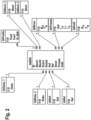
- the Fig. 2 shows the graphical representation of a database structure according to the invention.
- the figure shows the tables, the data fields of the tables and the relationships between the tables of a relational database.
- the tblPoints table contains data sets with the points to be welded. Each data record is assigned a position on the workpiece. Furthermore, the data record references a data record from the table tblBDK via a 1:n relationship, in which data about the sheet metal/thickness combinations created and provided with target curves and reference curves are stored. This data record from the table tblBDK references data records in the tables tbl_Blech, tblDicke, tblSoll, tbIRef, tblStrom, tblProcess and tbl Kraft via further 1:n relationships.
- the table tblBlech describes the materials of the sheets 250 to be welded and the table tblThickness describes their thickness. For example, if two aluminum sheets with sheet thicknesses of 2 and 5 mm are welded, the data field Sheet1 and the data field Sheet2 reference the data record for the material aluminum in the table tblSheet. Furthermore, the data field Thickness1 references a data record 2 mm from the table tblThickness and the data field Thickness2 references the data record for a sheet thickness of 5 mm from the table tblThickness. This clearly describes the sheet metal/thickness combination of the materials to be welded.
- the data sets of the table tblSoll describe setpoint specifications, for example a current setpoint curve for the current controller 150, the data sets of the table tblRef describe reference curves for the process controller 160.
- the table tblSoll can also describe setpoint specifications for a force/torque controller 170 for the closing movement of the welding tool 200.
- a data record of the respective table is referenced via the data fields Target or Ref of the data record of the table tblBDK.
- the further data fields current, process and force of the table tbIBDK reference the controller parameters for the current controller 150, correction parameters for the process controller 160 and controller parameters for the force/or torque controller 170.
- the controller parameters are or correction parameters of the respective controllers are adjusted.
- the values are retrieved by the assignment device 130 or the parameterization device 140 using the BDK assigned to the point to be welded and the reference contained therein to the data fields of the tables tblStrom, tblProcess and tblKraft, as in Fig. 2 shown.
- Torque controller 170 it is therefore advantageously possible to have not only the setpoint curves for the current controller 150 and/or force controller 170, the reference curves for the process controller 160, but also the controller or correction parameters for the current controller 150, the process controller 160 and/or the force controller. / Torque controller 170 to be adapted to a BDK, with an advantageous setting of the parameters of the controller mentioned for the respective BDK.
- the Fig. 3 shows a program flowchart of the process steps.
- a first step 300 of the method the current point to be welded is read out from the list of points to be welded by the assignment device 130. A BDK and thus a data set is clearly assigned to the current point to be welded.
- step 310a of the method the setpoint curve for the current controller 150 is read from the data record.
- step 310b of the method the controller parameters for the current controller are read from the data record.
- step 320a of the method the setpoint curve is assigned to the current controller 150.
- step 320b the controller parameters for the current controller 150 are parameterized.
- step 330a of the method the reference curve for the process controller is read from the data record.
- step 330b the correction parameters for the process controller 160 are read from the data record.
- step 340a of the method the reference curve is assigned to the process controller 160.
- step 340b of the method the correction parameters for the process controller 160 are parameterized.
- step 350a of the method the setpoint curve for the force/torque controller is read from the data record.
- step 350b the parameters for the force/torque controller 170 are read from the data record.
- step 360a of the method the setpoint curve is assigned to the force/torque controller 170.
- step 360b of the method the parameters for the force/torque controller 170 are parameterized.
- step 370 of the method the control of the time course of the electrical current at the welding point, the detection of the time course of the current, a voltage, a force and/or a position at the welding point with the detection device 120, and the correction of the setpoint curve of the current regulator 150 by the process controller 160 and the regulation of the time course of the force at the welding point by the force/or torque controller 170 summarized.
- the present method is therefore particularly advantageous for processes in which a large number of welding points with complex, different sheet thickness combinations BDK have to be welded together.
- the method is particularly advantageous for body shell construction, in particular for automated welding processes in body shell construction, preferably in the course of motor vehicle production.
Landscapes
- Engineering & Computer Science (AREA)
- Mechanical Engineering (AREA)
- Resistance Welding (AREA)
Description
Die vorliegende Erfindung betrifft eine Widerstandsschweißvorrichtung, eine Datenbank für eine Widerstandsschweißvorrichtung und ein Verfahren zum Betreiben einer Widerstandsschweißvorrichtung, sowie einen Datensatz zur Verwendung mit einer Schweißsteuerung.The present invention relates to a resistance welding device, a database for a resistance welding device and a method for operating a resistance welding device, as well as a data record for use with a welding controller.
Das Widerstandsschweißen dient üblicherweise zur Herstellung einer Verbindung zwischen zwei Blechen bzw. Metallteilen. Eine Widerstandsschweißvorrichtung weist dafür zwei Schweißelektroden auf, zwischen denen ein Schweißstrom fließt. Dabei werden zum Schweißen üblicherweise Ströme von 5 kA bis einige 50 kA bei Schweißspannungen im Bereich von 1 bis 2,5 V verwendet. Bei den zu verbindenden Teilen kann es sich sowohl um Bleche gleicher als auch um Bleche unterschiedlicher Metallart und Dicke handeln. Die einzelnen Schweißvorgänge finden dabei in Zeitfenstern im Bereich von bis zu einer Sekunde statt. Es sind jedoch auch längere Zeiten möglich. Beispielsweise werden im Zuge des automatisierten Karosserierohbaus durch robotergeführte Schweißwerkzeuge unterschiedliche Werkstücke, z.B. Bleche, mittels Widerstandsschweißen miteinander verschweißt.Resistance welding is usually used to create a connection between two sheets of metal or metal parts. A resistance welding device has two welding electrodes between which a welding current flows. Currents of 5 kA to a few 50 kA with welding voltages in the range of 1 to 2.5 V are usually used for welding. The parts to be connected can be sheets of the same type or sheets of different metal types and thicknesses. The individual welding processes take place in time windows of up to one second. However, longer times are also possible. For example, in the course of automated body shell construction, different workpieces, e.g. sheets, are welded together using robot-guided welding tools using resistance welding.
Aus dem Stand der Technik, zum Beispiel der Offenlegung
Zum besseren Verständnis wird folgendes dargelegt: Die Prozessimpedanz setzt sich aus Stoffwiderständen und Kontaktwiderständen zusammen. Die Stoffwiderstände sind abhängig von dem Material und dem Zustand der Schweißelektroden, sowie von den beiden zu schweißenden Materialien. Die Kontaktwiderstände ergeben sich durch den Schweißprozess selbst, das heißt insbesondere durch die sich kontaktierenden Oberflächen, die entstehende Schweißlinse bzw. Schweißnaht und durch die Impedanz der Schweißelektroden. Die in der Schweißsteuerung oder extern hinterlegten Soll-Impedanzen werden im Folgenden als Referenzkurven bezeichnet. Die ASR nutzt den Unterschied zwischen der Referenzkurve und einer Messkurve der aktuellen Schweißung und passt den Schweißstrom und die Schweißzeit, also den Sollwertverlauf für einen Stromregler, entsprechend an.For a better understanding, the following is explained: The process impedance is made up of material resistance and contact resistance. The material resistances depend on the material and the condition of the welding electrodes, as well as on the two welding materials. The contact resistances result from the welding process itself, i.e. in particular from the surfaces that come into contact, the resulting weld lens or weld seam and the impedance of the welding electrodes. The target impedances stored in the welding control or externally are referred to below as reference curves. The ASR uses the difference between the reference curve and a measurement curve for the current weld and adjusts the welding current and the welding time, i.e. the setpoint curve for a current controller, accordingly.
Aus der
Mittels Widerstandsschweißen werden, wie bereits erwähnt, im automatisierten Karosseriebau unterschiedliche Werkstücke, zum Beispiel Bleche, miteinander verschweißt.As already mentioned, resistance welding is used to weld different workpieces, such as metal sheets, together in automated body construction.
Problematisch dabei ist, dass mehrere Fahrzeugmodelle mit unterschiedlichen Modellvarianten auf einer Fertigungslinie und mit einer Schweißsteuerung gefertigt werden. Je nachdem, wie die Fahrzeugmodelle auf dieser Linie einlaufen, werden die unterschiedlichsten Blechkombinationen geschweißt. Die Reihenfolge der Fahrzeuge ändert sich ständig. Parallel nimmt die Varianz der zu verscheißenden Blechkombinationen zu. Auch die Beschichtungen der Bleche unterscheiden sich immer mehr und die dazu notwendige Ansteuerung der Widerstandsschweißvorrichtung weicht bei unterschiedlichen Beschichtungen deutlich voneinander ab.The problem here is that several vehicle models with different model variants are manufactured on one production line and with one welding control. Depending on how the vehicle models arrive on this line, a wide variety of sheet metal combinations are welded. The order of the vehicles changes constantly. At the same time, the variance of the sheet metal combinations to be welded increases. The coatings on the sheets are also becoming more and more different and the necessary control of the resistance welding device differs significantly for different coatings.
Im Zuge des Herstellungsprozesses einer einzigen Karosserie können bis zu mehrere tausend Schweißpunkte (z.B. ca. 5.000 Schweißpunkte für ein Mittelklasse-Fahrzeug) bei mehreren hundert verschiedenen Werkstückdicken- und/oder Materialkombinationen (z.B. ca. 700 Kombinationen für ein Mittelklasse-Fahrzeug) automatisiert bearbeitet werden. Schweißsteuerungen erhalten deshalb Prozessführungsparameter - also Sollwerte oder Sollkurven - zur Steuerung des Schweißprozesses der zu verschweißenden Punkte, in Abhängigkeit von der Werkstückdicken- und/oder Materialkombinationen des jeweiligen Schweißpunktes. Im weiteren Verlauf dieser Schrift wird für die Werkstückmaterial und/oder Werkstückdicken Materialkombination der Begriff Blech-/Dickenkombination bzw. die Abkürzung BDK verwendet.During the manufacturing process of a single body, up to several thousand welding points (e.g. approx. 5,000 welding points for a mid-range vehicle) can be processed automatically with several hundred different workpiece thicknesses and/or material combinations (e.g. approx. 700 combinations for a mid-range vehicle). . Welding controls therefore receive process control parameters - i.e. target values or target curves - to control the welding process of the points to be welded, depending on the workpiece thickness and/or material combinations of the respective welding point. In the further course of this document the workpiece material and/or workpiece thicknesses will be discussed material combination, the term sheet metal/thickness combination or the abbreviation BDK is used.
Die Patentanmeldung
Aus der Patentanmeldung
Aus dem Recherchenbericht sind weiterhin folgende einschlägigen Dokumente aus dem Stand der Technik bekannt.The following relevant documents from the prior art are also known from the search report.
Die Druckschrift
Die Druckschrift
Die Anmeldung
Die Schrift
Die Schrift
Die Patentanmeldung
Die Patentanmeldung
Trotz ASR mit BDK-spezifischen Stromsollkurven und Referenzkurven kann es Anwendungsfälle geben, bei denen die Qualität der Schweißpunkte nicht stabil ist. Dies trifft insbesondere auf das Verschweißen von Aluminium Blechkombinationen mit variierenden Blechdicken zu, weil aufgrund der hohen spezifischen Leitfähigkeit von Aluminiumlegierungen die Wärmeumsetzung sehr gering und der Nebenschlusseinfluss groß ist. Problematisch ist auch das Verschweißen von Blechkombinationen aus verzinkten Stahl.Despite ASR with BDK-specific current target curves and reference curves, there may be applications in which the quality of the welding points is not stable. This applies in particular to the welding of aluminum sheet combinations with varying sheet thicknesses, because due to the high specific conductivity of aluminum alloys, the heat conversion is very low and the shunt influence is large. Welding sheet metal combinations made of galvanized steel is also problematic.
Es ist daher Aufgabe der vorliegenden Erfindung, eine Schweißsteuerung und ein Verfahren zum Steuern eines Schweißvorgangs bereitzustellen, mit welchen der Schweißprozess weiter verbessert werden kann. Insbesondere sollen eine Schweißsteuerung und ein Verfahren zum Steuern eines Schweißvorgangs bereitgestellt werden, bei welchen beim Schweißen mit einem Schweißwerkzeug für bisher als schwierig geltende Schweißverbindungen, eine konstantere Schweißqualität erzielt wird.It is therefore an object of the present invention to provide a welding control and a method for controlling a welding process with which the welding process can be further improved. In particular, a welding control and a method for controlling a welding process are to be provided, in which during welding a welding tool for welding connections that were previously considered difficult, achieving a more consistent welding quality.
Diese Aufgabe wird durch eine Widerstandsschweißvorrichtung mit einer Schweißsteuerung zur Ansteuerung eines Schweißwerkzeugs nach Anspruch 1 gelöst. Die Aufgabe wird zudem durch eine Datenbank für eine Widerstandsschweißvorrichtung nach Anspruch 10, ein Verfahren zum Betreiben einer Widerstandsvorrichtung nach Anspruch 15, und einen Datensatz mit den Merkmalen des Anspruchs 20 gelöst.This object is achieved by a resistance welding device with a welding control for controlling a welding tool according to
Der Erfindung liegt die Erkenntnis zugrunde, dass durch schweißpunktspezifisches Einstellen der Parameter der Regler der Schweißsteuerung die Schweißqualität und die Wiederholbarkeit einer Schweißung unter anderem bei schwierig geltenden Schweißverbindungen deutlich verbessert werden kann. Im Unterschied zu einem Prozessführungsparameter, wie einem Stromsollwert oder einer Referenzkurve, ist hier ein Reglerparameter gemeint wie z.B. die Verstärkung des Proportionalanteils KP oder die Nachstellzeit TN des Integralanteils eines PI-Reglers. Bei Schweißsteuerungen regelt ein Stromregler der Schweißsteuerung für die Schweißung eines Punktes einen vorgegebenen Schweißstrom. Der Sollwert wird einem Datensatz eines Speichermittels der Schweißsteuerung oder einer externen Datenbank entnommen und dem Stromregler als zeitlicher Sollwertverlauf durch eine spezielle Einrichtung der Schweißsteuerung zugeführt. Diese Einrichtung der Schweißsteuerung wird hier als Zuordnungseinrichtung bezeichnet.The invention is based on the finding that by setting the parameters of the welding control controllers specifically for the welding point, the welding quality and the repeatability of a weld can be significantly improved, among other things in the case of difficult welded connections. In contrast to a process control parameter, such as a current setpoint or a reference curve, what is meant here is a controller parameter such as the gain of the proportional component K P or the reset time T N of the integral component of a PI controller. In welding controls, a current regulator of the welding control regulates a predetermined welding current for welding a point. The setpoint is taken from a data set in a storage device of the welding control or an external database and fed to the current controller as a time setpoint curve by a special device in the welding control. This welding control device is referred to here as an allocation device.
Der Zuordnungseinrichtung wird erfindungsgemäß eine Parametrisierungseinrichtung hinzugefügt. Wird der Datensatz um besagte Parameter für den Stromregler ergänzt, kann die Parametrisierungseinrichtung die Parameter - also die Reglerparameter - des Stromreglers optimal an die zu verschweißende BDK anpassen. Der Schweißprozess kann weiter verbessert werden. Die Anpassung der Parameter für den Stromregler kann auf sehr effiziente Weise durch die ohnehin in einer Schweißsteuerung vorhandene Zuordnungseinrichtung erfolgen. Dafür müssen die Daten des Datensatzes für die BDK der zu verschweißenden Verbindung nur um spezielle Reglerparameter für den Stromregler ergänzt werden. Somit können zum Beispiel auf einfache Art und Weise die Reglerparameter Proportionalverstärkung KP und/oder die Nachstellzeit TN, aber auch weitere hier nicht explizit genannte Reglerparameter des Stromreglers optimal an die spezifische BDK angepasst werden. Damit ist es einfach und sehr effizient möglich, für jede zu verschweißende Blech-/Dickenkombination die optimale Einstellung und Parametrisierung des Stromreglers vorzunehmen. Der Ausschuss der Fertigungsanlage aufgrund von fehlerhaften Schweißverbindungen wird reduziert. Ferner wird eine verbesserte Regelung des Schweißprozesses ermöglicht, ohne dass zusätzliche Hardware benötigt wird, insbesondere ohne zusätzliche Sensoren.According to the invention, a parameterization device is added to the assignment device. If the data set is supplemented with the said parameters for the current controller, the parameterization device can optimally adapt the parameters - i.e. the controller parameters - of the current controller to the BDK to be welded. The welding process can be further improved. The parameters for the current regulator can be adjusted very efficiently using the allocation device that is already present in a welding control. To do this, the data in the data set for the BDK of the connection to be welded only needs to be supplemented with special controller parameters for the current controller. Thus, for example, the controller parameters proportional gain K P and/or the reset time T N , but also other controller parameters of the current controller not explicitly mentioned here, can be optimally adapted to the specific BDK in a simple manner. This makes it easy and very efficient to find the optimal setting and parameterization of the current controller for each sheet metal/thickness combination to be welded to be carried out. The production plant's rejects due to faulty welded connections are reduced. Furthermore, improved control of the welding process is made possible without the need for additional hardware, in particular without additional sensors.
Diese Vorteile ergeben sich in analoger Weise auch aus der Bereitstellung einer Datenbank mit den Merkmalen des Anspruchs 10, aus der Bereitstellung eines Verfahrens mit den Merkmalen des Anspruchs 15 und aus der Bereitstellung eines Datensatzes mit den Merkmalen des Anspruchs 20.These advantages also arise in an analogous manner from the provision of a database with the features of
Vorteilhafte weitere Ausgestaltungen werden in den abhängigen Ansprüchen angegeben.Advantageous further refinements are specified in the dependent claims.
Besonders vorteilhaft ist es die Korrekturparameter eines Prozessreglers der Schweißsteuerung an die unterschiedlichen BDK anzupassen. Unter Korrekturparameter werden hier die Reglerparameter des Prozessreglers verstanden. Auf einfache Art und Weise ist es mit der vorliegenden Erfindung möglich auch die Korrekturparameter des Prozessreglers an die zu verschweißende Blech-/Dickenkombination anzupassen. Dazu werden die Daten des Datensatzes für die BDK der zu verschweißenden Verbindung um Daten ergänzt, die einen oder mehrere Korrekturparameter des Prozessreglers individuell für diese spezifische BDK angeben. Beispielsweise können mit Hilfe der Korrekturparameter eine Anpassung von Schweißstrom und Schweißzeit gesteuert werden, als Reaktion des Prozessreglers auf eine Abweichung einer erfassen Größe - wie Strom - und der entsprechenden Referenzkurve. Die Schweißprozessregelung und dessen Parametrierung wird somit in Abhängigkeit von der zu verschweißenden BDK durchgeführt und nicht ausschließlich von einem Vergleich von Ist- und Referenzkurve. Dadurch kann der Schweißprozess weiter erheblich verbessert werden. Auf einfache und effiziente Weise ist es möglich die Korrekturparameter des Prozessreglers wie zum Beispiel die Verstärkung, also wie stark der Strom bei einer Prozessabweichung verstellt wird, und/oder die Verstärkung der Stromzeitverlängerung, also wie stark die Zeitdauer des Stromflusses bei einer Prozessabweichung verstellt wird, und/oder die Grenze der Stromverstellung, aber auch weitere hier nicht explizit genannte Korrekturparameter des Prozessreglers an die spezifische BDK anzupassen. Beispielsweise erfordert das Schweißen von Blechkombinationen aus verzinkten Stahl einen wesentlich kleineren Eingriff des Prozessreglers den Schweißstrom und die Schweißzeit betreffend als das Verschweißen von Blechkombinationen von unverzinkten Stahlblechen. Hier kann der Prozessregler höhere Ströme mit längerer Zeitdauer als Sollwerte an den Stromregler vorgeben. Auch ist der Durchmesser der Schweißpunkte bei verzinktem Stahlblechen kleiner, als bei unverzinkten Blechen, was zu einem erhöhten Verschleiß der Schweißelektroden führt. Der höhere Energieeintrag sowie das kleinere Toleranzband als auch der höhere Verschleiß der Elektroden erfordern eine höhere Leistung der Stromquelle, sowie einen exakten Abgleich der Regelungsparameter für eine dynamische Regelung. Dadurch kann auch z.B. der thermische und mechanische Stress der Elektroden reduziert werden. Die Parametrisierungseinrichtung der Schweißsteuerung stellt für jeden Schweißablauf die optimalen Korrekturparameter des Prozessreglers speziell für die aktuell zu verschweißende Blech-/Dicken-Kombination ein. Grundlage für dieses Vorgehen ist ein in der Datenbank hinterlegtes Wissen bzgl. des notwendigen Schweißprozesses in Bezug auf die Korrekturparameter des Prozessreglers. Erfindungsgemäß stellt nämlich die Datenbank bzw. ein darin abgelegter Datensatz eine Struktur z.B. in Form von vorgesehenen Tabellen bzw. Feldern zur Aufnahme von Werten bereit, in der das besagte Wissen in Form von -insbesondere für die jeweilige BDK angepassten - Korrekturparametern hinterlegt ist. Insbesondere können durch die Anpassung der Parameter des Prozessreglers an die BDK Schweißspritzer verhindert werden.It is particularly advantageous to adapt the correction parameters of a process controller of the welding control to the different BDK. Correction parameters here mean the controller parameters of the process controller. With the present invention it is also possible in a simple manner to adapt the correction parameters of the process controller to the sheet metal/thickness combination to be welded. For this purpose, the data in the data set for the BDK of the connection to be welded is supplemented by data that specify one or more correction parameters of the process controller individually for this specific BDK. For example, with the help of the correction parameters, an adjustment of the welding current and welding time can be controlled as a reaction of the process controller to a deviation of a recorded quantity - such as current - and the corresponding reference curve. The welding process control and its parameterization are therefore carried out depending on the BDK to be welded and not exclusively on a comparison of the actual and reference curve. This allows the welding process to be significantly improved. In a simple and efficient way, it is possible to adjust the correction parameters of the process controller such as the gain, i.e. how much the current is adjusted in the event of a process deviation, and/or the gain of the current time extension, i.e. how much the duration of the current flow is adjusted in the event of a process deviation, and/or to adapt the limit of the current adjustment, but also other correction parameters of the process controller not explicitly mentioned here, to the specific BDK. For example, the welding of sheet metal combinations made of galvanized steel requires a much smaller intervention by the process controller regarding the welding current and the welding time than the welding of sheet metal combinations made of ungalvanized steel sheets. Here the process controller can specify higher currents with longer durations as setpoints to the current controller. The diameter of the welding points on galvanized steel sheets is also smaller than on non-galvanized ones Sheet metal, which leads to increased wear on the welding electrodes. The higher energy input as well as the smaller tolerance band and the higher wear of the electrodes require a higher power source and an exact adjustment of the control parameters for dynamic control. This can also reduce the thermal and mechanical stress on the electrodes, for example. The parameterization device of the welding control sets the optimal correction parameters of the process controller for each welding process specifically for the sheet metal/thickness combination currently being welded. The basis for this procedure is knowledge stored in the database regarding the necessary welding process in relation to the correction parameters of the process controller. According to the invention, the database or a data record stored therein provides a structure, for example in the form of tables or fields provided for recording values, in which the said knowledge is stored in the form of correction parameters - in particular adapted for the respective BDK. In particular, welding spatter can be prevented by adapting the parameters of the process controller to the BDK.
Neuere bzw. hochwertige Schweißsteuerungen umfassen einen Antriebsregler, insbesondere einen Kraft-/Drehmomentregler für das Schweißwerkzeug, z.B. für den Schließantrieb einer Schweißzange. Wird der Datensatz der BDK um Reglerparameter für den Kraft-/Drehmomentregler ergänzt, lässt sich der Kraft-/Drehmomentregler spezifisch an die zu verschweißende BDK anpassen. Durch eine bessere Dosierung der Anpresskraft, wird einer Verformung des Schweißwerkzeugs entgegengewirkt und die Schweißelektroden können exakt positioniert werden. Der Schweißprozess wird weiter verbessert. Somit können zum Beispiel auf einfache Art und Weise die Parameter Verstärkung KP und/oder Nachstellzeit TN des Kraft-/Drehmomentreglers, aber auch weitere hier nicht explizit genannte Parameter des Kraft-/Drehmomentreglers optimal an die spezifische BDK angepasst werden. Damit ist es einfach und sehr effizient möglich, für jede zu verschweißende Blech-/Dickenkombination die optimale Einstellung des Kraft-/Drehmomentreglers vorzunehmen. Problematisch sind insbesondere Randschweißungen. Bei einer derartigen Randschweißung "rutschen" die Elektroden mit dem Aufschmelzen langsam seitlich von dem Werkstück herunter. Dies hat einen kontinuierlichen Kraftverlust zur Folge. Der Elektrodenantrieb regelt die Kraft ständig nach, es kommt zu Überschwingern bei der Regelung. Wenn man für Randschweißungen eigens angelegte BDK und entsprechende Datensätze für diese BDK vorsieht, können vorteilhaft und effizient die Reglerparameter des Kraft-/ oder Drehmomentreglers an diese schwierigen Schweißprozesse angepasst werden. Denkbar ist es insbesondere die Position des Schweißpunktes am Werkstück in die Parameterauswahl für den Kraft-/Drehmomentregler einzubeziehen. Damit kann die Qualität des Schweißprozesses bei Randschweißungen verbessert werden.Newer or high-quality welding controls include a drive controller, in particular a force/torque controller for the welding tool, for example for the closing drive of a welding gun. If the BDK data set is supplemented with controller parameters for the force/torque controller, the force/torque controller can be specifically adapted to the BDK to be welded. By better dosing the contact pressure, deformation of the welding tool is counteracted and the welding electrodes can be positioned precisely. The welding process is further improved. Thus, for example, the parameters gain K P and/or reset time T N of the force/torque controller, but also other parameters of the force/torque controller not explicitly mentioned here, can be optimally adapted to the specific BDK in a simple manner. This makes it easy and very efficient to make the optimal setting of the force/torque controller for each sheet/thickness combination to be welded. Edge welds are particularly problematic. With such an edge weld, the electrodes slowly "slide" down to the side of the workpiece as they melt. This results in a continuous loss of strength. The electrode drive constantly adjusts the force; overshoots occur during the control. If you provide BDK specifically created for edge welds and corresponding data sets for these BDK, the control parameters of the force or torque controller can be advantageously and efficiently adapted to these difficult welding processes. It is particularly conceivable to include the position of the welding point on the workpiece in the parameter selection for the force/torque controller to include. This can improve the quality of the welding process for edge welds.
Weitere Vorteile und Ausführungsformen ergeben sich aus den beigefügten Figuren:
Darin zeigen:
- Fig. 1
- schematisch eine bevorzugte Ausgestaltung einer erfindungsgemäßen Schweißvorrichtung,
- Fig. 2
- eine graphische Darstellung einer bevorzugten Ausgestaltung einer erfindungsgemäßen Datenbankstruktur und
- Fig. 3
- schematisch eine bevorzugte Ausführungsform des erfindungsgemäßen Verfahrens als ein Blockdiagramm.
Show in it:
- Fig. 1
- schematically a preferred embodiment of a welding device according to the invention,
- Fig. 2
- a graphic representation of a preferred embodiment of a database structure according to the invention and
- Fig. 3
- schematically a preferred embodiment of the method according to the invention as a block diagram.
In
Die Schweißsteuerung 10 umfasst einen Umrichter 100, ein Speichermittel 110, eine Erfassungseinrichtung 120, eine Zuordnungseinrichtung 130 mit einer Parametrisierungseinrichtung 140, einen Stromregler 150 und einen Prozessregler 160, einen Kraft-/Drehmomentregler 170 sowie eine Kommunikationseinrichtung 180.The
Der Schweißroboter 20 führt ein Schweißwerkzeug 200, das dazu dient die Schweißverbindung durch einen Stromfluss an den zu verbindenden Blechen 250, zum Beispiel einer Autokarosserie stoffschlüssig zu fügen. Das Schweißwerkzeug 200 umfasst zwei Schweißelektroden 210 mit hier nicht dargestellten Elektrodenkappen. Das Schweißwerkzeug 200 ist als C-Schweißzange ausgeführt, kann jedoch auch eine X-Zange oder ein anderes Schweißwerkzeug sein. Weiterhin umfasst der Schweißroboter 20 einen Schweißtransformator 220, eine Messeinrichtung 230 und eine Kommunikationseinrichtung 240. Mit der Messeinrichtung 230 wird der der Stromfluss durch die Schweißelektroden 210, die Spannung an den Schweißelektroden 210, die Kraft, die die Schweißelektroden 210 auf die Bleche 250 ausüben und/oder die Position der Schweißelektroden 210 gemessen. Mit der Kommunikationseinrichtung 240 werden die Daten der Messeinrichtung 230 über die Kommunikationseinrichtung 180 an die Erfassungseinrichtung 120 der Schweißsteuerung 10 übertragen. Die Übertragung kann analog als auch digital zum Beispiel über einen Feldbus oder auch drahtlos erfolgen.The
Der Umrichter 100 der Schweißsteuerung 10 wandelt die dreiphasige Netzspannung von der Netzfrequenz in eine Spannung einer Mittelfrequenz, die den Schweißtransformator 220 des Schweißroboters 20 speist. Der Schweißtransformator 220 stellt den Schweißstrom, der über die Schweißelektroden 210 und über die nicht dargestellten Elektrodenkappen durch die zu verbindenden Bleche 250 fließt zur Verfügung und dient als Gleichrichter sowie steuerbare Stromquelle. Die Höhe des Schweißstromes wird dabei durch den Stromregler 150 der Schweißsteuerung 10 geregelt, der seinerseits den Umrichter 100 ansteuert. Als Sollwert für den Stromregler 150 der Schweißsteuerung 10 dient eine Sollwertkurve. Die Zuordnungseinrichtung 130 liest aus einem Datensatz des Speichermittels 110 oder aus einer nicht dargestellten externen Datenbank eine Liste der zu verschweißenden Punkte aus. Anschließend liest die Zuordnungseinrichtung 130 aus der Liste der zu verscheißenden Punkte per Referenzierung einen Datensatz für die BDK des aktuellen zu verschweißenden Punktes aus. Der ausgelesene Datensatz für die BDK umfasst ein Datenfeld für die Sollwertkurve für den Stromregler 150. Die Sollwertkurve für den Stromregler 150 ist z.B. aus Segmenten konstanten Stromverlaufs zusammengesetzt, die durch linear steigende oder fallende Übergangssegmente verbunden sind und wird durch die Höhe der Ströme mit konstanten Verlauf und durch die Steigungen der Übergangssegmente beschrieben. Die Sollwertkurve für den Stromverlauf kann auch aus Wertepaaren, bestehend aus Zeitwerten und Stromwerten die durch einen zusätzlichen, nicht dargestellten Interpolator linear interpoliert werden oder aus einer beliebigen Kombination von linearen Segmenten mit Übergangssegmenten und Wertepaaren aus Zeit-/ und Stromwerten zusammengesetzt sein.The
Die Sollwertkurve für den Stromregler 150 wird von der Zuordnungseinrichtung 130 abgerufen und während des Schweißvorganges dem Prozessregler 160 an seinem oberen Eingang als Stromsollwertkurve zugeführt. In der nichtadaptiven Betriebsart KSR des Prozessreglers 160, wird diese Sollwertkurve unverändert an den Stromregler 150 weitergegeben.The setpoint curve for the
In der adaptiven Betriebsart ASR des Prozessreglers 160 wird der Unterschied der aktuellen Messkurve, die von der Erfassungseinrichtung 120 dem Prozessregler 160 an seinem unteren Eingang zugeführt wird, zu einer Referenzkurve, die von der Zuordnungseinrichtung 130 dem Prozessregler 160 an seinem mittleren Eingang zugeführt wird, bewertet und der Sollwertverlauf für den Stromregler 150 wird entsprechend der Prozessabweichung angepasst. Die Stellgröße des Prozessreglers 160 dient also dem Stromregler 150 als zeitlicher Verlauf des Stromsollwerts. Die Stellgröße des Stromreglers 150 ist ein Signal, insbesondere ein pulsweitenmoduliertes Signal, das dem Umrichter 100 zugeführt wird. Der Umrichter 100 steuert den Schweißtransformator 220 mit einem Wechselstrom auf seiner Primärseite an. Sekundärseitig ist der Schweißtransformator 220 mit der Schweißzange bzw. dem Schweißwerkzeug 200 am Schweißroboter 20 verbunden. Die Messeinrichtung 230 des Schweißroboters 20 misst den elektrischen Strom, der durch die Schweißelektroden 210 des Schweißwerkzeugs 200 fließt und überträgt diese Werte über die Kommunikationseinrichtungen 180 und 240 an die Erfassungseinrichtung 120. Der Istwert für den Stromregler 150 wird von der Erfassungseinrichtung 120 dem Stromregler 150 zugeführt. Der Stromregler 150 hat Reglerparameter wie eine an den Schweißtransformator 220 angepasste Verstärkung KP und/oder eine Nachstellzeit TN. Der von der Zuordnungseinrichtung 130 ausgelesene Datensatz umfasst auch diese Reglerparameter des Stromreglers 150. Die Parameter werden von der Parametrisierungseinrichtung 140 der Zuordnungseinrichtung 130 dem Stromregler 150 vor der aktuellen Schweißung als aktuelle Reglerparameter zugewiesen. Damit ist es in vorteilhafter Weise möglich, nicht nur die Sollwertkurve für den Stromregler 150, sondern auch die Reglerparameter für den Stromregler 150 an eine BDK des aktuellen Schweißpunktes mit einer vorteilhaften Einstellung des oder der Reglerparameter des Stromreglers 150, anzupassen. Der Stromregler 150 kann weitere, hier nicht explizit aufgeführte Reglerparameter haben. Der von der Zuordnungseinrichtung 130 ausgelesene Datensatz umfasst auch diese Reglerparameter und die Parametrisierungseinrichtung 140 weist sie dem Stromregler 150 vor der aktuellen Schweißung zu.In the adaptive operating mode ASR of the
Ein dem Stromregler 150 übergeordneter Prozessregler 160 korrigiert den, dem Stromregler 150 zuführten Sollwert und kann Abweichungen in der Schweißpunktqualität durch Anpassung des Schweißprozesses ausgleichen. Der von der Zuordnungseinrichtung 130 ausgelesene Datensatz umfasst dafür zumindest eine Referenzkurve. Die besagte Referenzkurve dient dem Prozessregler 160 als Sollwert. Die Referenzkurve kann eine während einer sogenannten Referenzschweißung aufgenommene Kurve des Impedanz-Verlaufes an der Schweißstelle sein. Zusätzlich oder alternativ kann die Referenzkurve auch der Verlauf einer auf die Schweißelektroden 210 ausgeübten Kraft und/oder die Position der Schweißelektroden 210 während dieser Referenzschweißung sein. Dabei stellen die Messsignale die Kraft- bzw. die Wegänderungen dar, die der Schweißprozess auf die Schweißelektroden 210, durch die thermische Ausdehnung des Schweißgutes und dem Einsinken der Schweißelektroden 210 in das aufgeschmolzene Schweißgut der Bleche 250 bewirkt. Der Istwert für den Prozessregler 160 wird von der Erfassungseinrichtung 120 erfasst und dem Prozessregler 160 zugeführt. Dieser Istwert kann der Impedanz-Verlauf an der Schweißstelle und/oder die auf die Schweißelektroden 210 ausgeübte Kraft und/oder die Position der Schweißelektroden 210 während der aktuellen Schweißung sein. Der Prozessregler 160 hat Korrekturparameter wie die Verstärkung der Stromsollwertkorrektur IP, die Verstärkung der Stromzeitverlängerung IT, und/oder die Grenze der Stromverstellung IG. Der von der Zuordnungseinrichtung 130 ausgelesene Datensatz umfasst auch Datenfelder für die Korrekturparameter des Prozessreglers 160. Diese in diesen Datenfeldern vorgehaltenen Werte werden dem Prozessregler 160 von der Parametrisierungseinrichtung 140 vor der aktuellen Schweißung als Korrekturparameter zugewiesen. Damit ist es in vorteilhafter Weise möglich, nicht nur die Sollwertkurven und/oder die Referenzkurven für den Prozessregler 160, sondern auch die Korrekturparameter des Prozessreglers 160 mit einer vorteilhaften Einstellung an eine BDK anzupassen. Der Prozessregler 160 kann weitere, hier nicht explizit aufgeführte Korrekturparameter aufweisen. Der von der Zuordnungseinrichtung 130 ausgelesene Datensatz umfasst auch diese Korrekturparameter und die Parametrisierungseinrichtung 140 weist sie dem Prozessregler 160 vor der aktuellen Schweißung zu.A
Ein weiterer Regler der Schweißsteuerung 10, ein Kraft-/oder Drehmomentregler 170 regelt die Kraft, die die Schweißelektroden 210 über ihre nicht dargestellten Elektrodenkappen auf die Bleche 250 ausüben. Dazu steuert der Regler 170 einen nicht dargestellten elektrischen Antrieb des Schweißwerkzeugs 22 an. Beim Kraft-/oder Drehmomentregler 170 kann es sich auch um einen Antriebsregler in einer Kraft-/ oder Drehmomentregelungsbetriebsart handeln. Der von der Zuordnungseinrichtung 130 ausgelesene Datensatz umfasst weiterhin eine Sollwertkurve für den Kraft- oder Drehmomentregler 170. Die Sollwertkurve dient dem Kraft- oder Drehmomentregler 170 als zeitlicher Verlauf des Kraft- oder Drehmomentsollwerts. Die Sollwertkurve für den Kraft-/oder Drehmomentregler 170 ist z.B. aus Segmenten konstanten Kraft-/oder Drehmomentverlaufs zusammengesetzt, die durch linear steigende oder fallende Übergangssegmente verbunden sind und wird durch die Höhe der Kräfte oder Drehmomente mit konstanten Verlauf und durch die Steigungen der Übergangssegmente beschrieben. Die Sollwertkurve für den Kraft-/Drehmomentverlauf kann auch durch Wertepaare, bestehend aus Zeitwerten und Kraft-/oder Drehmomentwerten, die durch einen zusätzlichen, nicht dargestellten Interpolator linear interpoliert werden, oder aus einer beliebigen Kombination von linearen Segmenten mit Übergangssegmenten und Wertepaaren aus Zeit-/ und Kraft-/oder Drehmomentwerten zusammengesetzt sein. Die Messeinrichtung 230 des Schweißwerkzeugs 200 misst die Kraft, die die Schweißelektroden 210 auf die Bleche 250 ausüben und überträgt diese Werte über die Kommunikationseinrichtungen 180, 240 an die Erfassungseinrichtung 120 der Schweißsteuerung 10. Der Istwert für den Kraft- oder Drehmomentregler 170 wird von der Erfassungseinrichtung 120 dem Kraft- oder Drehmomentregler 170 zugeführt. Der Kraft- oder Drehmomentregler 170 hat Reglerparameter wie eine Verstärkung KP oder eine Nachstellzeit TN. Der von der Zuordnungseinrichtung 130 ausgelesene Datensatz umfasst auch Reglerparameter des Kraft-/oder Drehmomentreglers 170. Diese Werte der entsprechenden Datenfelder des Datensatzes werden von der Parametrisierungseinrichtung 140 dem Kraft-/oder Drehmomentregler 170 vor der aktuellen Schweißung als Reglerparameter zugewiesen. Damit ist es in vorteilhafter Weise möglich, nicht nur die Sollwertkurven für den Kraft-/oder Drehmomentregler 170, sondern auch die Reglerparameter für den Kraft-/oder Drehmomentregler 170 mit einer vorteilhaften Einstellung der Reglerparameter an eine BDK anzupassen. Der Kraft-/oder Drehmomentregler 170 kann weitere, hier nicht explizit aufgeführte Reglerparameter haben. Der von der Zuordnungseinrichtung 130 ausgelesene Datensatz umfasst auch diese Reglerparameter und die Parametrisierungseinrichtung 140 weist sie dem Kraft-/oder Drehmomentregler 170 vor der aktuellen Schweißung zu.Another controller of the
Der Widerstandsschweißprozess besteht im Wesentlichen aus drei Phasen. Diese drei Phasen werden üblicherweise als Vorhaltezeit, Stromflussphase und Nachhaltezeit oder Abkühlphase bezeichnet.The resistance welding process essentially consists of three phases. These three phases are usually referred to as the lead time, the current flow phase and the hold time or cooling phase.
In der ersten Phase, der sogenannten Vorhaltezeit, drücken die zwei Schweißelektroden 210 die zu verbindenden Bleche 250 bzw. Metallteile unter Einwirkung einer Kraft, welche durch den Antrieb des Schweißwerkzeugs 200 bereitgestellt wird, zusammen. Dabei fließt in dieser Phase noch kein Strom zwischen den Schweißelektroden 210.In the first phase, the so-called lead time, the two
In der zweiten Phase, der Stromflussphase, werden die Bleche 250 durch einen Stromfluss zwischen den Schweißelektroden 210 aufgeheizt und es bildet sich an den Verbindungsstellen durch die vom Strom erzeugte Wärme eine Schmelze aus.In the second phase, the current flow phase, the
Die dritte und letzte Phase des Widerstandsschweißprozesses ist die Nachhaltezeit bzw. Abkühlphase. In dieser Phase kühlt die Schmelze ab und erstarrt, so dass sich eine unlösbare Verbindung zwischen den Blechen 250 bzw. Metallteilen bildet. Erst nachdem die Schmelze genügend abgekühlt und insbesondere, erstarrt ist, werden die Schweißelektroden 210 durch den Antrieb des Schweißwerkzeugs wieder geöffnet und die nun verbundenen Bleche 250 können aus der Schweißvorrichtung entnommen werden.The third and final phase of the resistance welding process is the hold time or cooling phase. In this phase, the melt cools and solidifies, so that an inseparable connection is formed between the
Mit Hilfe der drei Regler, Stromregler 150, Prozessregler 160 und Kraft-/oder Drehmomentregler 170 steuert die Schweißsteuerung 10 den erforderlichen Ablauf zum Schließen und Öffnen des Schweißwerkzeugs 200, die über die Schweißelektroden 210 auf die Bleche 250 aufgebrachte Kraft, die Stromzeit, die Stromhöhe und gegebenenfalls den zeitlichen Stromverlauf.With the help of the three controllers,
Durch die vorliegende Erfindung erfolgt in allen drei Phasen des Widerstandsschweißprozesses eine optimale Anpassung der Regler 150, 160, 170, der Schweißsteuerung an die jeweilige konkrete Blech-/Dickenkombination der zu verschweißenden Bleche 250 mit eigens für diese BDK hinterlegten Reglerparametern und Korrekturparametern. Damit kann der Widerstandsschweißprozess in Bezug auf die zeitliche Dauer und die erforderliche Prozessstabilität erheblich verbessert werden.Through the present invention, in all three phases of the resistance welding process, the
Die
In der Figur sind die Tabellen, die Datenfelder der Tabellen und die Beziehungen zwischen den Tabellen einer relationalen Datenbank dargestellt.The figure shows the tables, the data fields of the tables and the relationships between the tables of a relational database.
Die Tabelle tblPunkte enthält Datensätze mit den zu verschweißenden Punkten. Jedem Datensatz ist eine Position am Werkstück zugeordnet. Weiterhin referenziert der Datensatz über eine 1 :n-Beziehung einen Datensatz der Tabelle tblBDK in der Daten über die angelegten und mit Sollkurven und Referenzkurven versehenen Blech-/Dickenkombinationen abgelegt sind. Dieser Datensatz der Tabelle tblBDK referenziert über weitere 1:n Beziehungen Datensätze in den Tabellen tbl_Blech, tblDicke, tblSoll, tbIRef, tblStrom, tblProzess und tbl Kraft.The tblPoints table contains data sets with the points to be welded. Each data record is assigned a position on the workpiece. Furthermore, the data record references a data record from the table tblBDK via a 1:n relationship, in which data about the sheet metal/thickness combinations created and provided with target curves and reference curves are stored. This data record from the table tblBDK references data records in the tables tbl_Blech, tblDicke, tblSoll, tbIRef, tblStrom, tblProcess and tbl Kraft via further 1:n relationships.
Die Tabelle tblBlech beschreibt die Materialien der zu verschweißenden Bleche 250 und die Tabelle tblDicke beschreibt deren Dicke. Werden zum Beispiel zwei Aluminiumbleche mit den Blechdicken 2 und 5 mm verschweißt, referenzieren das Datenfeld Blech1 und das Datenfeld Blech2 den Datensatz für das Material Aluminium der Tabelle tblBlech. Weiter referenziert das Datenfeld Dicke1 einen Datensatz 2 mm der Tabelle tblDicke und das Datenfeld Dicke2 referenziert den Datensatz für eine Blechstärke von 5 mm der Tabelle tblDicke. Damit ist die Blech-/Dickenkombination der zu verschweißenden Materialien eindeutig beschrieben.The table tblBlech describes the materials of the
Die Datensätze der Tabelle tblSoll, beschreiben Sollwertvorgaben z.B. eine StromSollwertkurve für den Stromregler 150, die Datensätze der Tabelle tblRef beschreiben Referenzkurven für den Prozessregler 160. Die Tabelle tblSoll kann auch Sollwertvorgaben für einen Kraft/-Drehmomentregler 170 für die Schließbewegung des Schweißwerkzeugs 200 beschreiben. Ein Datensatz der jeweiligen Tabelle wird über die Datenfelder Soll bzw. Ref des Datensatzes der Tabelle tblBDK referenziert.The data sets of the table tblSoll describe setpoint specifications, for example a current setpoint curve for the
Erfindungsgemäß referenzieren die weiteren Datenfelder Strom, Prozess und Kraft der Tabelle tbIBDK die Reglerparameter für den Stromregler 150, Korrekturparameter für den Prozessregler 160 und Reglerparameter für den Kraft-/oder Drehmomentregler 170. Mit Hilfe der Werte der Datenfelder der genannten drei Tabellen werden die Regler- bzw. Korrekturparameter der jeweiligen Regler angepasst. Der Abruf der Werte durch die Zuordnungseinrichtung 130 bzw. die Parametrisierungseinrichtung 140 erfolgt mit Hilfe der dem zu verschweißenden Punkt zugeordneten BDK und der darin enthaltenen Referenz auf die Datenfelder der Tabellen tblStrom, tblProzess und tblKraft, wie in
Denkbar ist es auch, die Parameter für den Stromregler 150 entsprechend des verwendeten Schweißtransformators 220 einzustellen. Bei einem Wechsel des Schweißtransformators 220 kann ein anderer Reglerparametersatz für den Stromregler 150 eingestellt sein. Dazu kann ein zusätzliches, hier nicht dargestelltes Datenfeld TrafoTyp in die Tabelle tblBDK aufgenommen werden, wobei entsprechend dem darin referenzierten Schweißtransformator die vorgenannten Werte der Tabelle tblStrom für die BDK in an den Schweißtransformator angepassten Varianten vorgehalten werden.It is also conceivable to set the parameters for the
Die
In einem ersten Schritt 300 des Verfahrens erfolgt das Auslesen des aktuellen zu verschweißenden Punktes aus der Liste der zu verschweißenden Punkte durch die Zuordnungseinrichtung 130. Dem aktuellen zu verschweißenden Punkt ist eine BDK und damit ein Datensatz eindeutig zugeordnet.In a
Im Schritt 310a des Verfahrens wird die Sollwertkurve für den Stromregler 150 aus dem Datensatz ausgelesen.In
Im Schritt 310b des Verfahrens werden die Reglerparameter für den Stromregler aus dem Datensatz ausgelesen.In
Im Schritt 320a des Verfahrens wird die Sollwertkurve an den Stromregler 150 zugewiesen.In
Im Schritt 320b werden die Reglerparameter für den Stromregler 150 parametrisiert.In
Im Schritt 330a des Verfahrens wird die Referenzkurve für den Prozessregler aus dem Datensatz ausgelesen.In
Im Schritt 330b werden die Korrekturparameter für den Prozessregler 160 aus dem Datensatz ausgelesen.In
Im Schritt 340a des Verfahrens wird die Referenzkurve an den Prozessregler 160 zugewiesen. Im Schritt 340b des Verfahrens werden die Korrekturparameter für den Prozessregler 160 parametrisiert.In
Im Schritt 350a des Verfahrens wird die Sollwertkurve für den Kraft-/Drehmomentregler aus dem Datensatz ausgelesen.In
Im Schritt 350b werden die Parameter für den Kraft-/Drehmomentregler 170 aus dem Datensatz ausgelesen.In
Im Schritt 360a des Verfahrens wird die Sollwertkurve an den Kraft-/Drehmomentregler 170 zugewiesen.In
Im Schritt 360b des Verfahrens werden die Parameter für den Kraft-/Drehmomentregler 170 parametrisiert.In
Im Schritt 370 des Verfahrens sind die Regelung des zeitlichen Verlaufs des elektrischen Stromes an der Schweißstelle, das Erfassen des zeitlichen Verlaufs des Stroms, einer Spannung, einer Kraft und/oder einer Position an der Schweißstelle mit der Erfassungseinrichtung 120, die Korrektur der Sollwertkurve des Stromreglers 150 durch den Prozessregler 160 und die Regelung des zeitlichen Verlaufs der Kraft an der Schweißstelle durch den Kraft- /oder Drehmomentregler 170 zusammengefasst.In
Das vorliegende Verfahren bietet sich daher besonders vorteilhafterweise für Prozesse an, bei welchem eine Vielzahl von Schweißpunkten mit komplexen, verschiedenen Blechdickenkombinationen BDK miteinander zu verschweißen sind. Beispielsweise eignet sich das Verfahren besonders vorteilhaft für den Karosserierohbau, insbesondere für automatisierte Schweißprozesse im Karosserierohbau, vorzugsweise im Zuge einer Kraftfahrzeugproduktion.The present method is therefore particularly advantageous for processes in which a large number of welding points with complex, different sheet thickness combinations BDK have to be welded together. For example, the method is particularly advantageous for body shell construction, in particular for automated welding processes in body shell construction, preferably in the course of motor vehicle production.
Weitere mögliche Implementierungen der Erfindung umfassen auch nicht explizit genannte Kombinationen von zuvor beschriebenen Merkmalen oder Ausführungsformen. Dabei wird der Fachmann auch Einzelaspekte als Verbesserungen oder Ergänzungen zu der jeweiligen Grundform der Erfindung hinzufügen. Die Erfindung ist in den Ansprüchen beschrieben.Further possible implementations of the invention also include combinations of features or embodiments described above that are not explicitly mentioned. The expert will also do this Add individual aspects as improvements or additions to the respective basic form of the invention. The invention is described in the claims.
- 11
- WiderstandsschweißvorrichtungResistance welding device
- 1010
- SchweißsteuerungWelding control
- 100100
- UmrichterInverter
- 110110
- Speichermittelstorage means
- 120120
- ErfassungseinrichtungDetection device
- 130130
- ZuordnungseinrichtungMapping facility
- 140140
- ParametrisierungseinrichtungParameterization facility
- 150150
- StromreglerCurrent regulator
- 160160
- ProzessreglerProcess controller
- 170170
- Kraft-/ DrehmomentreglerForce/torque controller
- 180180
- KommunikationseinrichtungCommunication facility
- 2020
- SchweißroboterWelding robots
- 200200
- SchweißwerkzeugWelding tool
- 210210
- SchweißelektrodenWelding electrodes
- 220220
- SchweißtransformatorWelding transformer
- 230230
- MesseinrichtungMeasuring device
- 240240
- KommunikationseinrichtungCommunication facility
- 250250
- Blechesheets
- tblPunktetblPoints
-
Tabelle der zu verschweißenden Schweißpunkte
ID Primärschlüssel
PosX X-Position am Werkstück
PosY Y-Position am Werkstück
ID_BDK Fremdschlüssel auf Datensatz der Tabelle tblBDKTable of weld points to be welded
ID primary key
PosX X position on the workpiece
PosY Y position on the workpiece
ID_BDK Foreign key on record of table tblBDK - tblBlechtblSheet
-
Tabelle der Blechmaterialien
ID Primärschlüssel
Blech MaterialTable of sheet metal materials
ID primary key
Sheet metal material - tblDicketblThickness
-
Tabelle der Blechdicken
ID Primärschlüssel
Dicke BlechdickeSheet thickness table
ID primary key
Thick sheet thickness - tblSolltbl target
-
Tabelle der Sollwerte
ID Primärschlüssel
Soll Beschreibung des Sollwert-Verlaufs, z.B. SollstromkurveTable of setpoints
ID primary key
Target Description of the target value curve, e.g. target current curve - tblReftblRef
-
Tabelle der Referenzkurven
ID Primärschlüssel
Soll Beschreibung des Referenzkurven-VerlaufsTable of reference curves
ID primary key
Should Description of the reference curve progression - tblStromtbl current
-
Tabelle der Reglerparameter des Stromreglers
ID Primärschlüssel
KP Verstärkung für den Proportionalanteil
TN Nachstellzeit für den IntegralanteilTable of current regulator parameters
ID primary key
K P Gain for the proportional component
T N reset time for the integral component - tblProzesstblProcess
-
Tabelle der Korrekturparameter des Prozessreglers
ID Primärschlüssel
IP Verstärkung der Stromsollwertkorrektur
IT Verstärkung der Stromzeitverlängerung
IG Grenze der StromverstellungTable of correction parameters of the process controller
ID primary key
I P Amplification of the current setpoint correction
I T Reinforcement of the current time extension
I G Limit of current adjustment - tblKrafttblForce
-
Tabelle der Reglerparameter des Kraft-/Drehmomentreglers
ID Primärschlüssel
KP Verstärkung für den Proportionalanteil
TN Nachstellzeit für den IntegralanteilTable of controller parameters of the force/torque controller
ID primary key
K P Gain for the proportional component
T N reset time for the integral component - tblBDKtblBDK
-
Tabelle der Bleck-Dickenkombination
ID Primärschlüssel
Blech1 erster Fremdschlüssel auf Datensatz der Tabelle tblBlech
Blech2 zweiter Fremdschlüssel auf Datensatz der Tabelle tblBlech
Dicke1 erster Fremdschlüssel auf Datensatz der Tabelle tblDicke
Dicke2 zweiter Fremdschlüssel auf Datensatz der Tabelle tblDicke
Soll Fremdschlüssel auf Datensatz der Tabelle tblSoll
Ref Fremdschlüssel auf Datensatz der Tabelle tblRef
Strom Fremdschlüssel auf Datensatz der Tabelle tblStrom
Prozess Fremdschlüssel auf Datensatz der Tabelle tblProzess
Kraft Fremdschlüssel auf Datensatz der Tabelle tblKraftBleck thickness combination table
ID primary key
Blech1 first foreign key on data record of table tblBlech
Blech2 second foreign key on data record of table tblBlech
Thickness1 first foreign key on record of table tblThickness
Thickness2 second foreign key on record of table tblThickness
Should foreign key on data record of table tblSoll
Ref Foreign key on record of table tblRef
Current foreign key on record of table tblStrom
Process foreign key on record of table tblProcess
Force foreign key on record of table tblForce
Claims (20)
- Resistance welding apparatus having a welding controller (10) for controlling a welding tool (200), wherein the welding controller (10) comprises• an assignment device (130) and• a first regulator (150),and the assignment device (130) is configured to read a present point to be welded from a list of points to be welded, to read a first setpoint curve from a data set in a database that is assigned to the present point to be welded and to assign the first setpoint curve to the first regulator (150), and the first regulator (150) is configured to regulate a temporal profile of an electrical current at the present point to be welded according to the first setpoint curve by means of at least one first regulator parameter,characterized in thatthe data set (tblBDK, tblStrom) in the database has at least one first value (tblStrom:KP, tblStrom:TN) for the first regulator parameter, and the assignment device (130) has a parameterization device (140) which is configured to read the first value from the data set for the point to be currently welded and to parameterize the first regulator parameter of the first regulator (150) using the first value.
- Resistance welding apparatus according to Claim 1, characterized in that the first regulator (150) of the welding controller (10) is a current regulator.
- Resistance welding apparatus according to Claim 2, characterized in that the at least first regulator parameter is at least a proportional gain of the current regulator or a reset time of the current regulator.
- Resistance welding apparatus according to one of the preceding claims,wherein the welding controller (10) comprises• a capture device (120) and• a second regulator (160),wherein the capture device (120) is configured to capture a temporal profile of a current, a voltage, a force and/or a position when welding a point,the assignment device (130) is configured to read at least one first reference curve from the data set in the database that is assigned to the present point to be welded and to assign the reference curve to the second regulator (160),and the second regulator (160) is configured to use at least one first correction parameter to correct the setpoint curve supplied to the first regulator (150) by the assignment device (130) on the basis of discrepancies between the reference curve and the temporal profile of the current, the voltage, the force and/or the position that is captured by the capture device (120), characterized in thatthe data set (tblBDK, tblProzess) in the database has at least one second value (tblProzess:IP, tblProzess:IT, tblProzess:IG) for the first correction parameter, and in that the parameterization device (140) is configured to parameterize the first correction parameter of the second regulator (160) using the second value.
- Resistance welding apparatus according to Claim 4, characterized in that the second regulator (160) of the welding controller (10) is a process regulator.
- Resistance welding apparatus according to Claim 5, characterized in that the at least first correction parameter is at least a gain of the current regulation by the process regulator, a limit of the current adjustment by the process regulator or a gain of the current time extension by the process regulator (160).
- Resistance welding apparatus according to one of the preceding claims, wherein the welding controller (10) comprises a third regulator (170) for controlling a drive of the welding tool, and the assignment device (130) is configured to read a second setpoint curve from the data set in the database and to assign the second setpoint curve to the third regulator (170), and the third regulator (170) is configured to use at least one second regulator parameterto regulate a temporal profile of a force or a torque for the present point to be welded according to the second setpoint curve by means of the drive of the welding tool (200),characterized in thatthe data set (tblBDK, tblKraft) has at least one third value (tblKraft:KP, tblKraft:TN) for the second regulator parameter, and in that the parameterization device (140) is configured to parameterize the second regulator parameter of the third regulator (170) using the third value.
- Resistance welding apparatus according to Claim 7, characterized in that the third regulator (170) of the welding controller (10) is a regulator of an electrical drive of the welding tool, having a force regulating operating mode or a torque regulating operating mode.
- Resistance welding apparatus according to Claim 8, characterized in that the at least second regulator parameter of the third regulator (170) is at least a proportional gain or a reset time of the force regulator or of the torque regulator of the drive regulator of the electrical drive of the welding tool (200).
- Database for a resistance welding apparatus according to one of Claims 1 to 9, having at least one data set (tblBDK) which has, in particular, a primary key (tblBDK, ID) for a sheet metal/thickness combination and can be assigned to a welding point via this primary key, wherein at least one setpoint curve (tblSoll, Soll) for the first regulator (150) of the welding controller (10) is assigned to the data set,
characterized
in that at least one first value (tblStrom:KP, tblStrom:TN) for the first regulator parameter of the first regulator (150) of the welding controller (10) is assigned to the data set (tblBdK), wherein the first value, in particular, represents at least a proportional gain or a reset time of a current regulator. - Database according to Claim 10 for a resistance welding apparatus according to one of Claims 4 to 6, wherein at least one reference curve (tblRef:Ref) for the second regulator (160) of the welding controller (10) is assigned to the data set (tblBDK),
characterized
in that at least one second value (tblProzess:IP, tblProzess:IT, tblProzess:IG) for the first correction parameter of the second regulator (160) of the welding controller (10) is assigned to the data set (tblBDK), wherein the second value, in particular, is at least a gain of the current regulation, a gain of the current time extension or a limit of the current adjustment by a process regulator. - Database according to either of Claims 10 and 11 for a resistance welding apparatus according to one of Claims 7 to 9, wherein at least one second setpoint curve (tblSoll:Soll) for the third regulator (170) of the welding controller (10) is assigned to the data set (tblBDK),
characterized
in that at least one third value (tblKraft:KP, tblKraft:TN) for a second regulator parameter of the third regulator (170) of the welding controller (10) is assigned to the data set (tblBDK), wherein the third value, in particular, represents at least a proportional gain or a reset time of a force regulator or a torque regulator. - Database according to one of Claims 10 to 12 for a resistance welding apparatus according to one of Claims 1 to 9, characterized in that the database is held in a storage means (110) of the welding controller (10).
- Database according to one of Claims 10 to 12 for a resistance welding apparatus according to one of Claims 1 to 9, characterized in that the database is held on a server which is accessed by the welding controller (10).
- Method for operating a resistance welding apparatus according to one of Claims 1 to 9 with a database according to one of Claims 10 to 14, having the steps of• using the assignment device (130) to read (300) a present point to be welded from a list of points to be welded,• using the assignment device (130) to read (310a) a first setpoint curve from a data set in the database that is assigned to the present point to be welded,• using the assignment device (130) to assign (320a) the first setpoint curve to the first regulator (150), and• using the first regulator (150) to regulate (370) the temporal profile of an electrical current according to the first setpoint curve,characterized in thatbefore the step of• regulating (370) the temporal profile of the electrical current,the steps of• using the parameterization device (140) to read (310b) at least one first value from the data set,• using the parameterization device (140) to parameterize (320b) at least one first regulator parameter of the first regulator (150) using the first valueare carried out.
- Method according to Claim 15 for operating a resistance welding apparatus according to one of Claims 4 to 9,wherein, before the step of• regulating (370) the temporal profile of the electrical current,the steps of• using the assignment device (130) to read (330a) at least one first reference curve from the data set and• using the assignment device (130) to assign (340a) the first reference curve to the second regulator (160) are carried out, and wherein, during the step of• regulating (370) the temporal profile of the electrical current,the steps of• using the capture device (120) to capture (370) the temporal profile of a current, voltage, a force and/or a position and• using the second regulator (160) to correct (370) the setpoint curve of the first regulator (150) on the basis of discrepancies between the reference curve and the temporal profile of the current, the voltage, the force and/or the position that is captured by the capture device (120) by means of at least one first correction parameterare carried out,characterizedin that, before the step of• regulating (370) the temporal profile of the electrical current,the steps of• using the assignment device (130) to read (330b) at least one second value from the data set,• using the parameterization device (140) to parameterize (340b) at least one first correction parameter of the second regulator (160) using the second valueare carried out.
- Method according to Claim 15 or Claim 16 for operating a resistance welding apparatus according to one of Claims 7 to 9, wherein, before the step of• regulating (370) the temporal profile of the electrical current,the steps of• using the assignment device (130) to read (350a) a second setpoint curve from the data set,• using the assignment device (130) to assign (360a) the second setpoint curve to the third regulator (170) are carried out, and wherein, during the step of• regulating (370) the temporal profile of the electrical current,a step of• using the third regulator (170) to regulate (370) a temporal profile of a force or a torque of the drive of the welding tool using at least one second regulator parameteris carried out,characterized in thatbefore the step of• regulating (370) a temporal profile of a force or a torque,the steps of• using the assignment device (130) to read (350b) at least one third value from the data set,• using the parameterization device (140) to parameterize (360b) at least one second regulator parameter of the third regulator (170) using the third valueare carried out.
- Computer program which causes a resistance welding apparatus (1) according to one of Claims 1 to 9 to carry out a method according to one of Claims 15 to 17 when it is executed on the welding controller (10) of the resistance welding apparatus (1).
- Machine-readable storage medium with a computer program according to Claim 18 stored thereon.
- Data set for use with a welding controller (10) according to one of Claims 1 to 9 and/or for holding in a database according to one of Claims 10 to 14 of a welding controller (10), having a structure which provides the following:• a primary key (tblBDK:ID) which allows the data set to be assigned to a welding point from a list of welding points (tblPunkte), in particular represented by a specific identification of a sheet metal/thickness combination (ID_BDK),• a setpoint curve (tblSoll:Soll) for application to at least one current regulator (150) of the welding controller (10), and• at least one additional value (tblStrom:KP, tblStrom:TN, tblProzess:IP, tblProzess:IT, tblProzess:IG) intended for parameterizing a current regulator (150) of the welding controller (10) and/or intended for parameterizing a process regulator (160) of the welding controller (10).
Applications Claiming Priority (1)
| Application Number | Priority Date | Filing Date | Title |
|---|---|---|---|
| DE102018217670.1A DE102018217670A1 (en) | 2018-10-16 | 2018-10-16 | Device and method for operating a resistance welding device |
Publications (3)
| Publication Number | Publication Date |
|---|---|
| EP3639963A2 EP3639963A2 (en) | 2020-04-22 |
| EP3639963A3 EP3639963A3 (en) | 2020-05-06 |
| EP3639963B1 true EP3639963B1 (en) | 2024-02-07 |
Family
ID=67766042
Family Applications (1)
| Application Number | Title | Priority Date | Filing Date |
|---|---|---|---|
| EP19193526.1A Active EP3639963B1 (en) | 2018-10-16 | 2019-08-26 | Device and method for operating a resistance welding device |
Country Status (5)
| Country | Link |
|---|---|
| US (1) | US11845139B2 (en) |
| EP (1) | EP3639963B1 (en) |
| CN (1) | CN111055002B (en) |
| DE (1) | DE102018217670A1 (en) |
| ES (1) | ES2977799T3 (en) |
Families Citing this family (3)
| Publication number | Priority date | Publication date | Assignee | Title |
|---|---|---|---|---|
| JP6810820B1 (en) * | 2020-05-01 | 2021-01-06 | 株式会社向洋技研 | Resistance welding equipment |
| CN111745273B (en) * | 2020-07-22 | 2021-11-05 | 上海又力光电科技有限公司 | Motor rotor step-up and step-down welding control method and device |
| CN112526359B (en) * | 2020-10-23 | 2022-11-18 | 风帆有限责任公司 | Lead-acid storage battery through-wall welding spot detection method |
Family Cites Families (23)
| Publication number | Priority date | Publication date | Assignee | Title |
|---|---|---|---|---|
| JPS4737828U (en) * | 1971-05-24 | 1972-12-26 | ||
| JPS60124475A (en) * | 1983-12-09 | 1985-07-03 | Hitachi Ltd | Method and device for controlling profiling of weld line |
| DE4020342A1 (en) * | 1990-06-23 | 1992-01-09 | Innovationsgesellschaft Fuer F | METHOD FOR MAINTAINING THE DYNAMIC AREA (REGULATORY AREA) OF THE PROCESS CONTROL IN WELDING, IN PARTICULAR TO COMPENSATE ELECTRODE WEAR IN RESISTANT SPOT WELDING AND DEVICE FOR CARRYING OUT THE PROCESS |
| US5219391A (en) * | 1991-12-06 | 1993-06-15 | Eaton Corporation | Transmission shifter having automatic adjustment of control parameters |
| DE9317013U1 (en) * | 1993-11-06 | 1995-03-02 | Kuka Schweißanlagen + Roboter GmbH, 86165 Augsburg | Welding tool |
| US5552575A (en) * | 1994-07-15 | 1996-09-03 | Tufts University | Scan welding method and apparatus |
| US5960174A (en) * | 1996-12-20 | 1999-09-28 | Square D Company | Arbitration method for a communication network |
| US6506996B2 (en) * | 2001-05-11 | 2003-01-14 | General Motors Corporation | System and method for performing preventative maintenance upon spot welding guns |
| WO2003008145A1 (en) * | 2001-07-12 | 2003-01-30 | Kuka Schweissanlagen Gmbh | Resistance welding device and control method |
| DE10334478B4 (en) | 2003-07-29 | 2006-04-13 | Adam Opel Ag | Method and apparatus for resistance welding |
| DK1812200T3 (en) * | 2004-10-13 | 2009-09-07 | Dritte Patentportfolio Beteili | Device for carrying out a joining, separating or surface treatment process, in particular a welding process |
| US20070221629A1 (en) * | 2006-03-22 | 2007-09-27 | Vernon Fernandez | Resistance spot welding system and method |
| DE102006038768A1 (en) | 2006-08-17 | 2008-03-13 | Evangelisches Krankenhaus Düsseldorf | Device for fixing body parts in the initial treatment of fractures |
| DE102006060197A1 (en) * | 2006-12-18 | 2008-06-26 | MV Marketing und Vertriebs-GmbH & Co. KG Wieländer + Schill | Apparatus and method for resistance welding |
| DE102009016798A1 (en) * | 2009-04-07 | 2010-10-14 | Daimler Ag | Method and control unit for monitoring a quality of welding points of a resistance welding gun |
| DE102009019624A1 (en) * | 2009-04-30 | 2010-11-04 | Robert Bosch Gmbh | Method for determining at least one controller parameter of a control element in a web tension control loop for a processing machine |
| MX2012009188A (en) * | 2010-02-12 | 2012-11-30 | Illinois Tool Works | Memory with weld bank data structure for welding applications; computerized welding system with such memory; method of storing welding data in a relational database in such memory. |
| JP5450150B2 (en) * | 2010-02-18 | 2014-03-26 | 株式会社神戸製鋼所 | Control method of tip-base metal distance by arc welding system and arc welding system |
| JP2012095442A (en) * | 2010-10-27 | 2012-05-17 | Daihen Corp | Welding power supply device |
| DE102013218138A1 (en) * | 2013-09-11 | 2015-03-12 | Robert Bosch Gmbh | Welding device and welding process for production plant |
| DE102013221273A1 (en) * | 2013-10-21 | 2015-04-23 | Robert Bosch Gmbh | Method for monitoring and controlling a quality of welds |
| DE102015225050A1 (en) | 2015-12-14 | 2017-06-14 | Robert Bosch Gmbh | Method for creating a database for performing welding processes |
| DE102016226252A1 (en) * | 2016-12-28 | 2018-06-28 | Robert Bosch Gmbh | DEVICE AND METHOD FOR DETERMINING WELDING TASKS FOR A WELDING SYSTEM |
-
2018
- 2018-10-16 DE DE102018217670.1A patent/DE102018217670A1/en active Pending
-
2019
- 2019-08-26 ES ES19193526T patent/ES2977799T3/en active Active
- 2019-08-26 EP EP19193526.1A patent/EP3639963B1/en active Active
- 2019-10-01 US US16/589,562 patent/US11845139B2/en active Active
- 2019-10-15 CN CN201910979075.1A patent/CN111055002B/en active Active
Also Published As
| Publication number | Publication date |
|---|---|
| CN111055002A (en) | 2020-04-24 |
| EP3639963A3 (en) | 2020-05-06 |
| EP3639963A2 (en) | 2020-04-22 |
| DE102018217670A1 (en) | 2020-04-16 |
| US11845139B2 (en) | 2023-12-19 |
| ES2977799T3 (en) | 2024-08-30 |
| US20200114460A1 (en) | 2020-04-16 |
| CN111055002B (en) | 2023-11-21 |
Similar Documents
| Publication | Publication Date | Title |
|---|---|---|
| EP3639963B1 (en) | Device and method for operating a resistance welding device | |
| DE102006056051B4 (en) | Robot with control for additional axes | |
| EP2903811B1 (en) | Method for controlling a ceramic or metal powder press, and ceramic or metal powder press | |
| EP2243585A1 (en) | Method and device for controlling a positioning device for welding | |
| EP3639962A1 (en) | Method for testing quality during the resistance welding of workpieces | |
| DE60317987T2 (en) | Spot welding device and method for controlling the pressing force of a welding gun | |
| DE69708519T2 (en) | Spot welding device and a method for controlling the device | |
| EP3680050A2 (en) | Method for testing welding tongs for resistance welding of workpieces | |
| EP0717673B1 (en) | Resistance-welding method | |
| DE102011018653A1 (en) | Resistance-welding apparatus comprises first main electrode and second main electrode for introducing welding current into workpiece to be welded, where one of the main electrodes is a part of an electrode arrangement, and adjusting unit | |
| DE10144286C1 (en) | Process for judging the quality of a welding joint between two sheet metal parts during resistance welding comprises reducing the distance between the welding electrodes in a closing phase of the welding tongs | |
| EP2199879A1 (en) | Device and method for minimising dynamic pulling mistakes | |
| EP3760360B1 (en) | Welding control for a welding device and method for reducing vibrations of a welding tool | |
| EP3546084B1 (en) | Method for connecting at least two workpieces by means of a punch rivet device and punch rivet device | |
| DE102019218554A1 (en) | Method and device for resistance welding | |
| DE102015215190A1 (en) | Method and device for carrying out a welding process | |
| EP3892412B1 (en) | Method of dynamically setting control thresholds for welding control, and corresponding welding control and computer program | |
| EP3915712B1 (en) | Method of optimizing welding parameters for welding control, method of providing a trained algorithm for machine learning, welding control, computer program and computer-readable data medium | |
| EP4063057A1 (en) | Method for the resistance welding of workpieces | |
| EP4382247A1 (en) | Device and method for adjusting the position of a plier-shaped tool | |
| EP3760359B1 (en) | Welding control for a welding tool, welding installation, and method for controlling the force of a welding tool | |
| EP3854509B1 (en) | Welding control device and method for generating force values in the control of a welding tool | |
| EP3808491B1 (en) | Method for the resistance welding of workpieces | |
| EP0735443A2 (en) | Neural network for compensating a position deviation in machining equipments for work pieces | |
| EP3854510B1 (en) | Welding control device and method for validating force values in the control of a welding tool |
Legal Events
| Date | Code | Title | Description |
|---|---|---|---|
| PUAI | Public reference made under article 153(3) epc to a published international application that has entered the european phase |
Free format text: ORIGINAL CODE: 0009012 |
|
| STAA | Information on the status of an ep patent application or granted ep patent |
Free format text: STATUS: THE APPLICATION HAS BEEN PUBLISHED |
|
| PUAL | Search report despatched |
Free format text: ORIGINAL CODE: 0009013 |
|
| AK | Designated contracting states |
Kind code of ref document: A2 Designated state(s): AL AT BE BG CH CY CZ DE DK EE ES FI FR GB GR HR HU IE IS IT LI LT LU LV MC MK MT NL NO PL PT RO RS SE SI SK SM TR |
|
| AX | Request for extension of the european patent |
Extension state: BA ME |
|
| RAP1 | Party data changed (applicant data changed or rights of an application transferred) |
Owner name: ROBERT BOSCH GMBH |
|
| AK | Designated contracting states |
Kind code of ref document: A3 Designated state(s): AL AT BE BG CH CY CZ DE DK EE ES FI FR GB GR HR HU IE IS IT LI LT LU LV MC MK MT NL NO PL PT RO RS SE SI SK SM TR |
|
| AX | Request for extension of the european patent |
Extension state: BA ME |
|
| RIC1 | Information provided on ipc code assigned before grant |
Ipc: B23K 11/11 20060101AFI20200330BHEP Ipc: B23K 11/25 20060101ALI20200330BHEP Ipc: B23K 101/18 20060101ALN20200330BHEP Ipc: G05B 13/00 20060101ALI20200330BHEP Ipc: B23K 101/00 20060101ALN20200330BHEP |
|
| STAA | Information on the status of an ep patent application or granted ep patent |
Free format text: STATUS: REQUEST FOR EXAMINATION WAS MADE |
|
| 17P | Request for examination filed |
Effective date: 20201106 |
|
| RBV | Designated contracting states (corrected) |
Designated state(s): AL AT BE BG CH CY CZ DE DK EE ES FI FR GB GR HR HU IE IS IT LI LT LU LV MC MK MT NL NO PL PT RO RS SE SI SK SM TR |
|
| STAA | Information on the status of an ep patent application or granted ep patent |
Free format text: STATUS: EXAMINATION IS IN PROGRESS |
|
| 17Q | First examination report despatched |
Effective date: 20210217 |
|
| RIC1 | Information provided on ipc code assigned before grant |
Ipc: B23K 101/18 19900101ALN20230111BHEP Ipc: B23K 101/00 19900101ALN20230111BHEP Ipc: G05B 13/00 19680901ALI20230111BHEP Ipc: B23K 11/25 19900101ALI20230111BHEP Ipc: B23K 11/11 19900101AFI20230111BHEP |
|
| RIC1 | Information provided on ipc code assigned before grant |
Ipc: B23K 101/18 20060101ALN20230830BHEP Ipc: B23K 101/00 20060101ALN20230830BHEP Ipc: G05B 13/00 20060101ALI20230830BHEP Ipc: B23K 11/25 20060101ALI20230830BHEP Ipc: B23K 11/11 20060101AFI20230830BHEP |
|
| GRAP | Despatch of communication of intention to grant a patent |
Free format text: ORIGINAL CODE: EPIDOSNIGR1 |
|
| STAA | Information on the status of an ep patent application or granted ep patent |
Free format text: STATUS: GRANT OF PATENT IS INTENDED |
|
| RIC1 | Information provided on ipc code assigned before grant |
Ipc: B23K 101/18 20060101ALN20231006BHEP Ipc: B23K 101/00 20060101ALN20231006BHEP Ipc: G05B 13/00 20060101ALI20231006BHEP Ipc: B23K 11/25 20060101ALI20231006BHEP Ipc: B23K 11/11 20060101AFI20231006BHEP |
|
| INTG | Intention to grant announced |
Effective date: 20231114 |
|
| RIC1 | Information provided on ipc code assigned before grant |
Ipc: B23K 101/18 20060101ALN20231106BHEP Ipc: B23K 101/00 20060101ALN20231106BHEP Ipc: G05B 13/00 20060101ALI20231106BHEP Ipc: B23K 11/25 20060101ALI20231106BHEP Ipc: B23K 11/11 20060101AFI20231106BHEP |
|
| GRAS | Grant fee paid |
Free format text: ORIGINAL CODE: EPIDOSNIGR3 |
|
| GRAA | (expected) grant |
Free format text: ORIGINAL CODE: 0009210 |
|
| STAA | Information on the status of an ep patent application or granted ep patent |
Free format text: STATUS: THE PATENT HAS BEEN GRANTED |
|
| AK | Designated contracting states |
Kind code of ref document: B1 Designated state(s): AL AT BE BG CH CY CZ DE DK EE ES FI FR GB GR HR HU IE IS IT LI LT LU LV MC MK MT NL NO PL PT RO RS SE SI SK SM TR |
|
| REG | Reference to a national code |
Ref country code: GB Ref legal event code: FG4D Free format text: NOT ENGLISH |
|
| REG | Reference to a national code |
Ref country code: CH Ref legal event code: EP |
|
| REG | Reference to a national code |
Ref country code: DE Ref legal event code: R096 Ref document number: 502019010528 Country of ref document: DE |
|
| REG | Reference to a national code |
Ref country code: IE Ref legal event code: FG4D Free format text: LANGUAGE OF EP DOCUMENT: GERMAN |
|
| REG | Reference to a national code |
Ref country code: LT Ref legal event code: MG9D |
|
| REG | Reference to a national code |
Ref country code: NL Ref legal event code: MP Effective date: 20240207 |
|
| PG25 | Lapsed in a contracting state [announced via postgrant information from national office to epo] |
Ref country code: IS Free format text: LAPSE BECAUSE OF FAILURE TO SUBMIT A TRANSLATION OF THE DESCRIPTION OR TO PAY THE FEE WITHIN THE PRESCRIBED TIME-LIMIT Effective date: 20240607 |
|
| PG25 | Lapsed in a contracting state [announced via postgrant information from national office to epo] |
Ref country code: LT Free format text: LAPSE BECAUSE OF FAILURE TO SUBMIT A TRANSLATION OF THE DESCRIPTION OR TO PAY THE FEE WITHIN THE PRESCRIBED TIME-LIMIT Effective date: 20240207 |
|
| PG25 | Lapsed in a contracting state [announced via postgrant information from national office to epo] |
Ref country code: GR Free format text: LAPSE BECAUSE OF FAILURE TO SUBMIT A TRANSLATION OF THE DESCRIPTION OR TO PAY THE FEE WITHIN THE PRESCRIBED TIME-LIMIT Effective date: 20240508 |
|
| PG25 | Lapsed in a contracting state [announced via postgrant information from national office to epo] |
Ref country code: HR Free format text: LAPSE BECAUSE OF FAILURE TO SUBMIT A TRANSLATION OF THE DESCRIPTION OR TO PAY THE FEE WITHIN THE PRESCRIBED TIME-LIMIT Effective date: 20240207 Ref country code: NL Free format text: LAPSE BECAUSE OF FAILURE TO SUBMIT A TRANSLATION OF THE DESCRIPTION OR TO PAY THE FEE WITHIN THE PRESCRIBED TIME-LIMIT Effective date: 20240207 Ref country code: RS Free format text: LAPSE BECAUSE OF FAILURE TO SUBMIT A TRANSLATION OF THE DESCRIPTION OR TO PAY THE FEE WITHIN THE PRESCRIBED TIME-LIMIT Effective date: 20240507 |
|
| PG25 | Lapsed in a contracting state [announced via postgrant information from national office to epo] |
Ref country code: RS Free format text: LAPSE BECAUSE OF FAILURE TO SUBMIT A TRANSLATION OF THE DESCRIPTION OR TO PAY THE FEE WITHIN THE PRESCRIBED TIME-LIMIT Effective date: 20240507 Ref country code: NO Free format text: LAPSE BECAUSE OF FAILURE TO SUBMIT A TRANSLATION OF THE DESCRIPTION OR TO PAY THE FEE WITHIN THE PRESCRIBED TIME-LIMIT Effective date: 20240507 Ref country code: NL Free format text: LAPSE BECAUSE OF FAILURE TO SUBMIT A TRANSLATION OF THE DESCRIPTION OR TO PAY THE FEE WITHIN THE PRESCRIBED TIME-LIMIT Effective date: 20240207 Ref country code: LT Free format text: LAPSE BECAUSE OF FAILURE TO SUBMIT A TRANSLATION OF THE DESCRIPTION OR TO PAY THE FEE WITHIN THE PRESCRIBED TIME-LIMIT Effective date: 20240207 Ref country code: IS Free format text: LAPSE BECAUSE OF FAILURE TO SUBMIT A TRANSLATION OF THE DESCRIPTION OR TO PAY THE FEE WITHIN THE PRESCRIBED TIME-LIMIT Effective date: 20240607 Ref country code: HR Free format text: LAPSE BECAUSE OF FAILURE TO SUBMIT A TRANSLATION OF THE DESCRIPTION OR TO PAY THE FEE WITHIN THE PRESCRIBED TIME-LIMIT Effective date: 20240207 Ref country code: GR Free format text: LAPSE BECAUSE OF FAILURE TO SUBMIT A TRANSLATION OF THE DESCRIPTION OR TO PAY THE FEE WITHIN THE PRESCRIBED TIME-LIMIT Effective date: 20240508 Ref country code: FI Free format text: LAPSE BECAUSE OF FAILURE TO SUBMIT A TRANSLATION OF THE DESCRIPTION OR TO PAY THE FEE WITHIN THE PRESCRIBED TIME-LIMIT Effective date: 20240207 Ref country code: BG Free format text: LAPSE BECAUSE OF FAILURE TO SUBMIT A TRANSLATION OF THE DESCRIPTION OR TO PAY THE FEE WITHIN THE PRESCRIBED TIME-LIMIT Effective date: 20240207 |
|
| PG25 | Lapsed in a contracting state [announced via postgrant information from national office to epo] |
Ref country code: PL Free format text: LAPSE BECAUSE OF FAILURE TO SUBMIT A TRANSLATION OF THE DESCRIPTION OR TO PAY THE FEE WITHIN THE PRESCRIBED TIME-LIMIT Effective date: 20240207 Ref country code: PT Free format text: LAPSE BECAUSE OF FAILURE TO SUBMIT A TRANSLATION OF THE DESCRIPTION OR TO PAY THE FEE WITHIN THE PRESCRIBED TIME-LIMIT Effective date: 20240607 |
|
| PG25 | Lapsed in a contracting state [announced via postgrant information from national office to epo] |
Ref country code: SE Free format text: LAPSE BECAUSE OF FAILURE TO SUBMIT A TRANSLATION OF THE DESCRIPTION OR TO PAY THE FEE WITHIN THE PRESCRIBED TIME-LIMIT Effective date: 20240207 Ref country code: PT Free format text: LAPSE BECAUSE OF FAILURE TO SUBMIT A TRANSLATION OF THE DESCRIPTION OR TO PAY THE FEE WITHIN THE PRESCRIBED TIME-LIMIT Effective date: 20240607 Ref country code: PL Free format text: LAPSE BECAUSE OF FAILURE TO SUBMIT A TRANSLATION OF THE DESCRIPTION OR TO PAY THE FEE WITHIN THE PRESCRIBED TIME-LIMIT Effective date: 20240207 Ref country code: LV Free format text: LAPSE BECAUSE OF FAILURE TO SUBMIT A TRANSLATION OF THE DESCRIPTION OR TO PAY THE FEE WITHIN THE PRESCRIBED TIME-LIMIT Effective date: 20240207 |
|
| REG | Reference to a national code |
Ref country code: ES Ref legal event code: FG2A Ref document number: 2977799 Country of ref document: ES Kind code of ref document: T3 Effective date: 20240830 |