EP3639736A1 - Procédé de mappage de contractions prématurées auriculaires et ventriculaires au cours du rythme sinusal - Google Patents
Procédé de mappage de contractions prématurées auriculaires et ventriculaires au cours du rythme sinusal Download PDFInfo
- Publication number
- EP3639736A1 EP3639736A1 EP19204600.1A EP19204600A EP3639736A1 EP 3639736 A1 EP3639736 A1 EP 3639736A1 EP 19204600 A EP19204600 A EP 19204600A EP 3639736 A1 EP3639736 A1 EP 3639736A1
- Authority
- EP
- European Patent Office
- Prior art keywords
- point
- pvc
- heart
- location
- mapping
- Prior art date
- Legal status (The legal status is an assumption and is not a legal conclusion. Google has not performed a legal analysis and makes no representation as to the accuracy of the status listed.)
- Granted
Links
- 238000013507 mapping Methods 0.000 title claims abstract description 62
- 230000033764 rhythmic process Effects 0.000 title claims description 22
- 238000000034 method Methods 0.000 title description 44
- 230000002861 ventricular Effects 0.000 title description 7
- 206010015856 Extrasystoles Diseases 0.000 title description 5
- 208000000418 Premature Cardiac Complexes Diseases 0.000 title description 5
- 230000001746 atrial effect Effects 0.000 title 1
- 230000004913 activation Effects 0.000 claims abstract description 51
- 239000000523 sample Substances 0.000 claims abstract description 16
- 208000009729 Ventricular Premature Complexes Diseases 0.000 claims description 18
- 230000002159 abnormal effect Effects 0.000 claims description 9
- 238000003780 insertion Methods 0.000 claims description 3
- 230000037431 insertion Effects 0.000 claims description 3
- 206010003119 arrhythmia Diseases 0.000 abstract description 30
- 238000002679 ablation Methods 0.000 description 28
- 206010047289 Ventricular extrasystoles Diseases 0.000 description 13
- 206010047302 ventricular tachycardia Diseases 0.000 description 9
- 230000006793 arrhythmia Effects 0.000 description 7
- 210000001519 tissue Anatomy 0.000 description 6
- 230000003126 arrythmogenic effect Effects 0.000 description 5
- 239000013598 vector Substances 0.000 description 5
- 230000000747 cardiac effect Effects 0.000 description 4
- 210000001174 endocardium Anatomy 0.000 description 4
- 230000006870 function Effects 0.000 description 4
- 210000005003 heart tissue Anatomy 0.000 description 4
- 230000007547 defect Effects 0.000 description 3
- 210000004165 myocardium Anatomy 0.000 description 3
- 230000037361 pathway Effects 0.000 description 3
- 238000012545 processing Methods 0.000 description 3
- 230000002123 temporal effect Effects 0.000 description 3
- 206010003658 Atrial Fibrillation Diseases 0.000 description 2
- 230000005856 abnormality Effects 0.000 description 2
- 210000005242 cardiac chamber Anatomy 0.000 description 2
- 229910003460 diamond Inorganic materials 0.000 description 2
- 239000010432 diamond Substances 0.000 description 2
- 230000000694 effects Effects 0.000 description 2
- 238000003384 imaging method Methods 0.000 description 2
- 230000003902 lesion Effects 0.000 description 2
- 230000008569 process Effects 0.000 description 2
- 230000001052 transient effect Effects 0.000 description 2
- 230000002792 vascular Effects 0.000 description 2
- 206010001497 Agitation Diseases 0.000 description 1
- 208000002102 Atrial Premature Complexes Diseases 0.000 description 1
- 230000002547 anomalous effect Effects 0.000 description 1
- 230000002763 arrhythmic effect Effects 0.000 description 1
- 206010003668 atrial tachycardia Diseases 0.000 description 1
- 230000015572 biosynthetic process Effects 0.000 description 1
- 230000008859 change Effects 0.000 description 1
- 239000013065 commercial product Substances 0.000 description 1
- 238000004590 computer program Methods 0.000 description 1
- 230000008602 contraction Effects 0.000 description 1
- 238000001816 cooling Methods 0.000 description 1
- 238000012631 diagnostic technique Methods 0.000 description 1
- 238000011156 evaluation Methods 0.000 description 1
- 238000010438 heat treatment Methods 0.000 description 1
- 230000001771 impaired effect Effects 0.000 description 1
- 238000002847 impedance measurement Methods 0.000 description 1
- 238000007689 inspection Methods 0.000 description 1
- 230000005865 ionizing radiation Effects 0.000 description 1
- 239000007788 liquid Substances 0.000 description 1
- 238000005259 measurement Methods 0.000 description 1
- 238000012986 modification Methods 0.000 description 1
- 230000004048 modification Effects 0.000 description 1
- 230000001575 pathological effect Effects 0.000 description 1
- 230000002028 premature Effects 0.000 description 1
- 238000002604 ultrasonography Methods 0.000 description 1
- 208000003663 ventricular fibrillation Diseases 0.000 description 1
Images


Classifications
-
- A—HUMAN NECESSITIES
- A61—MEDICAL OR VETERINARY SCIENCE; HYGIENE
- A61B—DIAGNOSIS; SURGERY; IDENTIFICATION
- A61B90/00—Instruments, implements or accessories specially adapted for surgery or diagnosis and not covered by any of the groups A61B1/00 - A61B50/00, e.g. for luxation treatment or for protecting wound edges
- A61B90/36—Image-producing devices or illumination devices not otherwise provided for
- A61B90/37—Surgical systems with images on a monitor during operation
-
- A—HUMAN NECESSITIES
- A61—MEDICAL OR VETERINARY SCIENCE; HYGIENE
- A61B—DIAGNOSIS; SURGERY; IDENTIFICATION
- A61B18/00—Surgical instruments, devices or methods for transferring non-mechanical forms of energy to or from the body
- A61B18/04—Surgical instruments, devices or methods for transferring non-mechanical forms of energy to or from the body by heating
- A61B18/12—Surgical instruments, devices or methods for transferring non-mechanical forms of energy to or from the body by heating by passing a current through the tissue to be heated, e.g. high-frequency current
- A61B18/14—Probes or electrodes therefor
- A61B18/1492—Probes or electrodes therefor having a flexible, catheter-like structure, e.g. for heart ablation
-
- A—HUMAN NECESSITIES
- A61—MEDICAL OR VETERINARY SCIENCE; HYGIENE
- A61B—DIAGNOSIS; SURGERY; IDENTIFICATION
- A61B5/00—Measuring for diagnostic purposes; Identification of persons
- A61B5/06—Devices, other than using radiation, for detecting or locating foreign bodies ; determining position of probes within or on the body of the patient
- A61B5/061—Determining position of a probe within the body employing means separate from the probe, e.g. sensing internal probe position employing impedance electrodes on the surface of the body
- A61B5/062—Determining position of a probe within the body employing means separate from the probe, e.g. sensing internal probe position employing impedance electrodes on the surface of the body using magnetic field
-
- A—HUMAN NECESSITIES
- A61—MEDICAL OR VETERINARY SCIENCE; HYGIENE
- A61B—DIAGNOSIS; SURGERY; IDENTIFICATION
- A61B5/00—Measuring for diagnostic purposes; Identification of persons
- A61B5/24—Detecting, measuring or recording bioelectric or biomagnetic signals of the body or parts thereof
- A61B5/25—Bioelectric electrodes therefor
- A61B5/279—Bioelectric electrodes therefor specially adapted for particular uses
- A61B5/28—Bioelectric electrodes therefor specially adapted for particular uses for electrocardiography [ECG]
- A61B5/283—Invasive
- A61B5/287—Holders for multiple electrodes, e.g. electrode catheters for electrophysiological study [EPS]
-
- A—HUMAN NECESSITIES
- A61—MEDICAL OR VETERINARY SCIENCE; HYGIENE
- A61B—DIAGNOSIS; SURGERY; IDENTIFICATION
- A61B5/00—Measuring for diagnostic purposes; Identification of persons
- A61B5/24—Detecting, measuring or recording bioelectric or biomagnetic signals of the body or parts thereof
- A61B5/316—Modalities, i.e. specific diagnostic methods
- A61B5/318—Heart-related electrical modalities, e.g. electrocardiography [ECG]
- A61B5/339—Displays specially adapted therefor
-
- A—HUMAN NECESSITIES
- A61—MEDICAL OR VETERINARY SCIENCE; HYGIENE
- A61B—DIAGNOSIS; SURGERY; IDENTIFICATION
- A61B5/00—Measuring for diagnostic purposes; Identification of persons
- A61B5/24—Detecting, measuring or recording bioelectric or biomagnetic signals of the body or parts thereof
- A61B5/316—Modalities, i.e. specific diagnostic methods
- A61B5/318—Heart-related electrical modalities, e.g. electrocardiography [ECG]
- A61B5/346—Analysis of electrocardiograms
- A61B5/349—Detecting specific parameters of the electrocardiograph cycle
- A61B5/363—Detecting tachycardia or bradycardia
-
- A—HUMAN NECESSITIES
- A61—MEDICAL OR VETERINARY SCIENCE; HYGIENE
- A61B—DIAGNOSIS; SURGERY; IDENTIFICATION
- A61B5/00—Measuring for diagnostic purposes; Identification of persons
- A61B5/68—Arrangements of detecting, measuring or recording means, e.g. sensors, in relation to patient
- A61B5/6846—Arrangements of detecting, measuring or recording means, e.g. sensors, in relation to patient specially adapted to be brought in contact with an internal body part, i.e. invasive
- A61B5/6847—Arrangements of detecting, measuring or recording means, e.g. sensors, in relation to patient specially adapted to be brought in contact with an internal body part, i.e. invasive mounted on an invasive device
- A61B5/6852—Catheters
-
- A—HUMAN NECESSITIES
- A61—MEDICAL OR VETERINARY SCIENCE; HYGIENE
- A61B—DIAGNOSIS; SURGERY; IDENTIFICATION
- A61B17/00—Surgical instruments, devices or methods, e.g. tourniquets
- A61B2017/00017—Electrical control of surgical instruments
- A61B2017/00022—Sensing or detecting at the treatment site
- A61B2017/00039—Electric or electromagnetic phenomena other than conductivity, e.g. capacity, inductivity, Hall effect
- A61B2017/00044—Sensing electrocardiography, i.e. ECG
- A61B2017/00048—Spectral analysis
- A61B2017/00053—Mapping
-
- A—HUMAN NECESSITIES
- A61—MEDICAL OR VETERINARY SCIENCE; HYGIENE
- A61B—DIAGNOSIS; SURGERY; IDENTIFICATION
- A61B18/00—Surgical instruments, devices or methods for transferring non-mechanical forms of energy to or from the body
- A61B2018/00315—Surgical instruments, devices or methods for transferring non-mechanical forms of energy to or from the body for treatment of particular body parts
- A61B2018/00345—Vascular system
- A61B2018/00351—Heart
-
- A—HUMAN NECESSITIES
- A61—MEDICAL OR VETERINARY SCIENCE; HYGIENE
- A61B—DIAGNOSIS; SURGERY; IDENTIFICATION
- A61B18/00—Surgical instruments, devices or methods for transferring non-mechanical forms of energy to or from the body
- A61B2018/00571—Surgical instruments, devices or methods for transferring non-mechanical forms of energy to or from the body for achieving a particular surgical effect
- A61B2018/00577—Ablation
-
- A—HUMAN NECESSITIES
- A61—MEDICAL OR VETERINARY SCIENCE; HYGIENE
- A61B—DIAGNOSIS; SURGERY; IDENTIFICATION
- A61B18/00—Surgical instruments, devices or methods for transferring non-mechanical forms of energy to or from the body
- A61B2018/00636—Sensing and controlling the application of energy
- A61B2018/00773—Sensed parameters
- A61B2018/00839—Bioelectrical parameters, e.g. ECG, EEG
-
- A—HUMAN NECESSITIES
- A61—MEDICAL OR VETERINARY SCIENCE; HYGIENE
- A61B—DIAGNOSIS; SURGERY; IDENTIFICATION
- A61B34/00—Computer-aided surgery; Manipulators or robots specially adapted for use in surgery
- A61B34/20—Surgical navigation systems; Devices for tracking or guiding surgical instruments, e.g. for frameless stereotaxis
- A61B2034/2046—Tracking techniques
- A61B2034/2051—Electromagnetic tracking systems
-
- A—HUMAN NECESSITIES
- A61—MEDICAL OR VETERINARY SCIENCE; HYGIENE
- A61B—DIAGNOSIS; SURGERY; IDENTIFICATION
- A61B5/00—Measuring for diagnostic purposes; Identification of persons
- A61B5/06—Devices, other than using radiation, for detecting or locating foreign bodies ; determining position of probes within or on the body of the patient
- A61B5/061—Determining position of a probe within the body employing means separate from the probe, e.g. sensing internal probe position employing impedance electrodes on the surface of the body
- A61B5/063—Determining position of a probe within the body employing means separate from the probe, e.g. sensing internal probe position employing impedance electrodes on the surface of the body using impedance measurements
-
- A—HUMAN NECESSITIES
- A61—MEDICAL OR VETERINARY SCIENCE; HYGIENE
- A61B—DIAGNOSIS; SURGERY; IDENTIFICATION
- A61B5/00—Measuring for diagnostic purposes; Identification of persons
- A61B5/24—Detecting, measuring or recording bioelectric or biomagnetic signals of the body or parts thereof
- A61B5/316—Modalities, i.e. specific diagnostic methods
- A61B5/318—Heart-related electrical modalities, e.g. electrocardiography [ECG]
- A61B5/346—Analysis of electrocardiograms
- A61B5/349—Detecting specific parameters of the electrocardiograph cycle
- A61B5/361—Detecting fibrillation
Definitions
- This invention relates to invasive medical devices. More particularly, this invention relates to identifying the anatomical origin of infrequent premature contractions of the heart chambers using an invasive probe.
- Cardiac arrhythmia such as atrial fibrillation, occurs when regions of cardiac tissue abnormally conduct electric signals to adjacent tissue, thereby disrupting the normal cardiac cycle and causing asynchronous rhythm.
- Procedures for treating arrhythmia include surgically disrupting the origin of the signals causing the arrhythmia, as well as disrupting the conducting pathway for such signals.
- By selectively ablating cardiac tissue by application of energy via a catheter it is sometimes possible to cease or modify the propagation of unwanted electrical signals from one portion of the heart to another.
- the ablation process destroys the unwanted electrical pathways by formation of non-conducting lesions.
- Mapping of electrical potentials in the heart is now commonly performed, using cardiac catheters comprising electrophysiological sensors for mapping the electrical activity of the heart.
- time-varying electrical potentials in the endocardium are sensed and recorded as a function of position inside the heart, and then used to map a local electrogram or local activation time.
- Activation time differs from point to point in the endocardium due to the time required for conduction of electrical impulses through the heart muscle.
- the direction of this electrical conduction at any point in the heart is conventionally represented by an activation vector, which is normal to an isoelectric activation front, both of which may be derived from a map of activation time.
- the rate of propagation of the activation front through any point in the endocardium may be represented as a velocity vector.
- Mapping the activation front and conduction fields aids the physician in identifying and diagnosing abnormalities, such as ventricular and atrial tachycardia and ventricular and atrial fibrillation, which result from areas of impaired electrical propagation in the heart tissue.
- Localized defects in the heart's conduction of activation signals may be identified by observing phenomena such as multiple activation fronts, abnormal concentrations of activation vectors, or changes in the velocity vector or deviation of the vector from normal values. Examples of such defects include re-entrant areas, which may be associated with signal patterns known as complex fractionated electrograms. Once a defect is located by such mapping, it may be ablated (if it is functioning abnormally) or otherwise treated to restore the normal function of the heart insofar as is possible.
- Mapping of the electrical activation time in the heart muscle requires that the location of the sensor within the heart be known at the time of each measurement.
- mapping was performed using a single movable electrode sensor inside the heart, which sensor measured activation time relative to a fixed external reference electrode. This technique, however, requires calibration, for example impedance calibrations with adjustments for impedance unrelated to that of the body.
- Mapping of electrical activation time using a single electrode was, furthermore, a lengthy procedure, generally performed under fluoroscopic imaging, and thereby exposing the patient to undesirable ionizing radiation.
- activation times at a single location may change between consecutive beats.
- a reentrant circuit that produces sinus PVC's is one pathological condition amenable to ablative treatment. Identifying the optimum point of line of ablation is a practical difficulty, even with modern electroanatomic mapping equipment.
- U.S. Patent No. 7,245,962 to Ciaccio et al. proposes a method and system for identifying and localizing a reentrant circuit isthmus in a heart of a subject during sinus rhythm.
- the method may include (a) receiving electrogram signals from the heart during sinus rhythm via electrodes, (b) creating a map based on the electrogram signals, (c) determining, based on the map, a location of the reentrant circuit isthmus in the heart, and (d) displaying the location of the reentrant circuit isthmus.
- U.S. Patent Application Publication No. 2009/0099468 to Thiagalingam et al. proposes locating a region of interest to ablate by recording electrogram data and corresponding spatial location data of an electrode that records the electrogram data; defining at least one reference channel containing a reference beat for determining temporal locations and against which beats of the recorded electrogram data are compared; examining the recorded electrogram data; defining a temporal location for each beat of the recorded electrogram data, and creating and analyzing an index of the temporal locations and other information of the beats within the recorded electrogram.
- a method of ablation which is carried out by inserting a probe into a heart of a living subject, urging the mapping electrode of the probe into a contacting relationship with a target tissue in a region of interest of the heart, and while detecting a cardiac arrhythmia, using the mapping electrode to associate a local activation time with a first location in the region of interest.
- the method is further carried out while detecting an absence of the cardiac arrhythmia and maintaining the contacting relationship, by associating the local activation time with a second location in the heart, assigning electrical data of the first location to the second location, and generating an electroanatomic map of the heart by including at least the second location for display thereof using the assigned electrical data of the first location.
- detecting a cardiac arrhythmia and detecting an absence of the cardiac arrhythmia comprise obtaining electrocardiographic signals via the mapping electrode, holding a series of the electrocardiographic signals in a buffer, selecting a first signal from the buffer as indicative of the cardiac arrhythmia, and selecting a second signal from the buffer as indicative of the absence of the cardiac arrhythmia.
- An additional aspect of the method includes navigating an ablation electrode to the assigned electrical data of the second location for ablation thereof referencing the electroanatomic map while navigating the ablation electrode.
- Another aspect of the method includes displaying the first location on the electroanatomic map and excluding the first location from computations in generating the electroanatomic map.
- detecting a cardiac arrhythmia includes identifying premature ventricular contractions wherein a cycle length thereof is within a predetermined range.
- the probe has multiple mapping electrodes and the method is carried out by acquiring multiple instances of the first location and the second location using respective ones of the mapping electrodes.
- Yet another aspect of the method is carried out by pace mapping and determining at respective locations a pace map correlation between signals produced during ventricular tachycardia and signals produced by pace mapping and wherein assigning electrical data includes assigning the pace map correlation of the first location to the second location.
- a medical apparatus including a probe, adapted for insertion into a heart, the probe including an elongated body, and a mapping electrode disposed on a distal portion of the body, a memory having programs stored therein, a display, and a processor linked to the display that is coupled to access the memory to execute the programs.
- the processor is connectable to receive an input provided by the mapping electrode, wherein the programs cause the processor to perform the steps of obtaining electrocardiographic signals from a target in the heart via the mapping electrode, holding a series of the electrocardiographic signals in a buffer, selecting a first signal from the buffer as indicative of a cardiac arrhythmia, the first signal occurring at a first point in time, and selecting a second signal from the buffer as indicative of an absence of the cardiac arrhythmia, the second signal occurring at a second point in time, associating a first local activation time of the target at a first location of the mapping electrode at the first point in time, associating a second local activation time of the target at a second location of the mapping electrode at the second point in time, assigning electrical data of the first location to the second location, generating an electroanatomic map based on the assigned electrical data at the second location, and presenting the electroanatomic map on the display, the electroanatomic map showing the first location and the second location.
- aspects of the present invention may be embodied in software programming code, which is typically maintained in permanent storage, such as a computer readable medium.
- software programming code may be stored on a client or a server.
- the software programming code may be embodied on any of a variety of known non-transitory media for use with a data processing system, such as a diskette, hard drive, electronic media or CD-ROM.
- the code may be distributed on such media, or may be distributed to users from the memory or storage of one computer system over a network of some type to storage devices on other computer systems for use by users of such other systems.
- physical coordinates of a point refers to coordinates of a point in the body of the subject that are determined with respect to fiducials or natural anatomic landmarks.
- map coordinates of a point as used herein refers to coordinates or a point relative to a reference point on an electroanatomic map.
- Fig. 1 is a pictorial illustration of a system 10 for performing ablative procedures on a heart 12 of a living subject, which is constructed and operative in accordance with a disclosed embodiment of the invention.
- the system comprises a catheter 14, which is percutaneously inserted by an operator 16 through the patient's vascular system into a chamber or vascular structure of the heart 12.
- the operator 16 who is typically a physician, brings the catheter's distal tip 18 into contact with the heart wall at an ablation target site.
- Electrical activation maps such as local activation time maps, may then be prepared, according to the methods disclosed in U.S. Patent Nos.
- Areas determined to be abnormal can be ablated by application of thermal energy, e.g., by passage of radiofrequency electrical current through wires in the catheter to one or more electrodes at the distal tip 18, which apply the radiofrequency energy to the myocardium.
- the energy is absorbed in the tissue, heating it to a point (typically about 50°C) at which it permanently loses its electrical excitability.
- this procedure creates non-conducting lesions in the cardiac tissue, which disrupt the abnormal electrical pathway causing the arrhythmia.
- the principles of the invention can be applied to different heart chambers to treat many different cardiac arrhythmias.
- the catheter 14 typically comprises a handle 20, having suitable controls on the handle to enable the operator 16 to steer, position and orient the distal end of the catheter as desired for the ablation.
- the distal portion of the catheter 14 contains position sensors (not shown) that provide signals to a positioning processor 22, located in a console 24.
- Ablation energy and electrical signals can be conveyed to and from the heart 12 through one or more ablation electrodes 32 located at or near the distal tip 18 via cable 34 to the console 24. Pacing signals and other control signals may be conveyed from the console 24 through the cable 34 and the electrodes 32 to the heart 12. Sensing electrodes 33, also connected to the console 24 are disposed between the ablation electrodes 32 and have connections to the cable 34.
- Wire connections 35 link the console 24 with body surface electrodes 30 and other components of a positioning sub-system.
- the electrodes 32 and the body surface electrodes 30 may be used to measure tissue impedance at the ablation site as taught in U.S. Patent No. 7,536,218, issued to Govari et al. , which is herein incorporated by reference.
- a temperature sensor (not shown), typically a thermocouple or thermistor, may be mounted on or near each of the electrodes 32.
- the console 24 typically contains one or more ablation power generators 25.
- the catheter 14 may be adapted to conduct ablative energy to the heart using any known ablation technique, e.g., radiofrequency energy, ultrasound energy, and laser-produced light energy. Such methods are disclosed in commonly assigned U.S. Patent Nos. 6,814,733 , 6,997,924 , and 7,156,816 , which are herein incorporated by reference.
- the positioning processor 22 is an element of a positioning subsystem in the system 10 that measures location and orientation coordinates of the catheter 14.
- the positioning subsystem comprises a magnetic position tracking arrangement that determines the position and orientation of the catheter 14 by generating magnetic fields in a predefined working volume and sensing these fields at the catheter, using field generating coils 28.
- the positioning subsystem may employ impedance measurement, as taught, for example in U.S. Patent No. 7,756,576 , which is hereby incorporated by reference, and in the above-noted U.S. Patent No. 7,536,218 .
- the catheter 14 is coupled to the console 24, which enables the operator 16 to observe and regulate the functions of the catheter 14.
- Console 24 includes a processor, preferably a computer with appropriate signal processing circuits.
- the processor is coupled to drive a monitor 29.
- the signal processing circuits typically receive, amplify, filter and digitize signals from the catheter 14, including signals generated by the above-noted sensors and a plurality of location sensing electrodes (not shown) located distally in the catheter 14.
- the digitized signals are received and used by the console 24 and the positioning system to compute the position and orientation of the catheter 14, and to analyze the electrical signals from the electrodes.
- the system 10 includes other elements, which are not shown in the figures for the sake of simplicity.
- the system 10 may include an electrocardiogram (ECG) monitor, coupled to receive signals from one or more body surface electrodes, to provide an ECG synchronization signal to the console 24.
- ECG electrocardiogram
- the system 10 typically also includes a reference position sensor, either on an externally-applied reference patch attached to the exterior of the subject's body, or on an internally-placed catheter, which is inserted into the heart 12 maintained in a fixed position relative to the heart 12. Conventional pumps and lines for circulating liquids through the catheter 14 for cooling the ablation site are provided.
- the medical procedure encompasses two stages, which may be accomplished in the same or different sessions.
- one object in a first stage, one object is to identify a point having the shortest local activation time in an arrhythmogenic region of the heart, referred to herein as a "PVC point".
- PVC point a point having the shortest local activation time in an arrhythmogenic region of the heart
- electroanatomic map is generated during the first stage.
- a second stage which occurs subsequent to the first stage, ablation of tissue in a region about the PVC point is performed. This is intended to interrupt automatic focal electrical activity and thereby prevent recurrence of the arrhythmia.
- the ablation electrode is navigated to the PVC point, which is a location on the electroanatomic map having the previously determined shortest local activation time.
- the patient has returned to sinus rhythm (SR).
- SR sinus rhythm
- sinus rhythm is employed herein for convenience as an example of a stable cardiac rhythm. It will be recalled that in the case of a patient with infrequent premature ventricular contractions, the abnormal heart rate originating from the ventricle appears infrequently and in short bursts (1-3 beats).
- the heart is mostly in sinus rhythm, except that from time to time short PVC bursts appear.
- PVC geometry the map's points
- the navigational catheter As a result, the ablated area will not be optimum to correct the patient's arrhythmia.
- the geometry of the heart differs during sinus rhythm, compared to its geometry during runs of ventricular tachycardia. In any event, it is desirable to accurately identify the physical location of the PVC point subsequent to its original determination.
- the following procedure is suitable for recording signals during mapping: record approximately 2.5 seconds of each mapping electrode, and capture PVC complexes in a beat buffer, which holds and graphically displays the last few beats recorded by the electrocardiogram. Typically, 10 beats are held in the beat buffer. Inspection of the beat buffer allows abnormal beats such as PVCs to be identified automatically or automatically with operator assistance, or manually by the operator. This phase may be automated according to an operator-selected cycle length range, a procedure, which is available in the above-noted CARTO system. Alternatively, the operator can manually acquire a point and the related beat buffer whenever he notices a PVC occurrence.
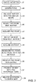
- Fig. 2 is a flow chart of a method of mapping arrhythmogenic areas producing ventricular premature beats while the subject is in sinus rhythm, in accordance with an embodiment of the invention.
- the figures described below are obtained using the CARTO 3 system, and are presented for convenience. However, the method may be performed with other imaging and mapping systems.
- a cardiac catheter having mapping electrodes and location sensors is inserted into the heart of a subject, using known methods.
- Catheters such as the PentaRay® NAV or Navistar® Thermocool® catheters, available from Biosense Webster, are suitable for use in initial step 37.
- the catheter is navigated to an abnormal area 39 ( Fig. 3 ).
- the beat buffer is filled with PVC and SR beats, and frozen to prevent its replacement by new beats.
- a beat showing a qualifying electrical abnormality e.g., a PVC
- a PVC point is automatically acquired based on the beat in the beat buffer that was chosen in step 45.
- the PVC point is acquired only if the cycle length of the selected beat falls within a predetermined range.
- Acquisition of the point comprises (1) determining the location the point, typically by using a location sensor to determine the position of the mapping electrode; (2) obtaining electrical data regarding the point from the mapping electrode, specifically its LAT; and (3) displaying the point on a map, e.g., an LAT map.
- the PVC point ideally has the earliest local activation time within the abnormal area; however this is not essential; points throughout the area 39 ( Fig. 3 ) may be acquired and displayed.
- a second beat is selected from the beat buffer.
- the second beat represents normal sinus rhythm for the patient.
- a second point is acquired and displayed on the same map as the PVC point.
- the locations of the PVC point and the SR point differ on the map, as explained above.
- electrical information e.g., the local activation time (LAT) of the PVC point that was established in step 47 is associated with the SR point in a single representative display by assigning the information to the SR point.
- LAT local activation time
- the PVC point is designated as "floating", meaning that the location of the PVC point may be indicated on LAT maps to indicate the disparity in the geometry of the heart when it is experiencing PVCs and SR.
- the PVC point is excluded from computations in the generation of such maps, and does not contribute to the map geometry and its electrical information.
- a LAT map generated during sinus rhythm reflects the geometry of the heart in sinus rhythm, including the location of the SR point.
- the map is adjusted to associate the electrical information of the PVC point at the location of the SR point.
- the LAT map is regenerated or adjusted to reflect the new data of the SR point.
- the SR map is presented with PVC electrical data. This version is referred to as a SR-PVC map.
- the SR-PVC map reflects the geometry of the heart during sinus rhythm, but has the activation time of the heart while experiencing PVCs.
- Steps 41-57 may be performed concurrently using different mapping electrodes, for example in a spline or lasso catheter. Additionally or alternatively steps 41- 57 may be iterated to present multiple SR points having reassigned PVC data on the map.
- ablation may be performed at the data-adjusted SR points with an ablation catheter displayed in SR locations.
- navigation of the ablation electrode may be guided by the SR-PVC map prepared in step 57.
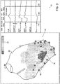
- Fig. 3 is a screen display 61 illustrating a representative local activation time map 63 of a heart 65 taken during performance of step 43, in accordance with an embodiment of the invention.
- the procedure for generating a local activation time map using a mapping catheter is known, and therefore its details are not discussed herein.
- Local activation times are typically coded using pseudocolor.
- Fig. 3 local activation times information is coded using patterns in accordance with a key 67. These patterns simulate the pseudocolors of an actual functional map.
- the area 39 has a relatively short LAT, and may be automatically flagged or selected by an operator as abnormal.
- the area 39 is circumscribed by an area 69 that has a relatively longer local activation time.
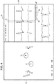
- Fig. 4 is a screen display 71 of a local activation time map 73 illustrating points of interest, in accordance with an embodiment of the invention.
- the map 73 shows the locations of PVC point 75 and SR point 77 that were obtained according to the procedure described above in reference to Fig. 2 .
- the points 75, 77 are enclosed by circles for improved visibility.
- the beats selected from the beat buffer in order to acquire the points 75, 77 are shown in right pane 79 with a window of interest interval 81.
- the right pane 79 also shows the activation times of the PVC point 75 and SR point 77 on a scale 83 in the lower right portion.
- the beats selected are the SR and PVC points indicated by circles 85, 87, respectively.
- isochronal points are acquired from an area of interest using the beat buffer during PVCs (step 45) and during sinus rhythm (step 49) are shown on the map 73 as the points 75, 77 respectively.
- the points 75, 77 were measured at different times, based on different beats in the beat buffer, and thus are associated with different time stamps. It is evident that they have different map locations.
- the LAT map displays the physical coordinates of an SR point whose associated activation time data was obtained at a different time.
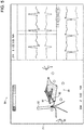
- FIG. 5 is a screen display 89 illustrating a role of a spline catheter in the generation of a local activation time map 91, in accordance with an embodiment of the invention.
- a spline catheter 93 e.g., the above noted Pentaray NAV catheter has been navigated such that an electrode of one of the spline, spline 95 is in contact with a point on a colored area 97, which has anomalous short activation times throughout.
- PVC and SR points may then be automatically acquired using one or more splines, and processed according to the method described above with reference to Fig. 2 .
- Another embodiment of the invention involves pace mapping, for example using PaSoTM software.
- Pace mapping is a diagnostic technique used for identification of ventricular tachycardia foci. This involves pacing the chamber at the ventricular tachycardia rate, then comparing a body surface 12-lead ECG acquired during pacing to an ECG recorded during clinical arrhythmia, either induced or previously recorded.
- the mapping phase is used to identify a pace-map correlation, i.e., a correlation between signals produced during ventricular tachycardia and signals produced by pace mapping, referred to as pace mapped - induced signal (PM-IS) correlation, as taught in commonly assigned U.S. Patent No. 7,907,994 to Stolarski et al. , which is herein incorporated by reference.
- a paced rhythm point serves as the PVC point from which PVC's originate.
- a map produced during pacing functions in the same manner as the map produced during sinus rhythm in the previous embodiment.
- Fig. 6 is a flow chart of a method of mapping arrhythmogenic areas producing ventricular premature beats while the subject is in sinus rhythm, in accordance with the preceding alternate embodiment of the invention. Some of the steps in Fig. 6 are performed in the same manner as those of Fig. 2 . Their description is not repeated in the interest of brevity.
- pacing is conducted at step 99.
- a point is then acquired at step 101, and pacing is then discontinued at step 103.
- the beat buffer is filled with pace-mapped (PM) beats and SR beats.
- PM pace-mapped
- a PM beat is selected from the beat buffer.
- step 109 the pace-mapped correlation based on the PM point acquired in step 47 is assigned to the SR point location that was selected in step 51.
- step 111 the PM point is presented as floating.
- the SR Map is presented with PM-IS correlation data, referred to as a SR-PM map.
Applications Claiming Priority (2)
| Application Number | Priority Date | Filing Date | Title |
|---|---|---|---|
| US14/024,859 US9642674B2 (en) | 2013-09-12 | 2013-09-12 | Method for mapping ventricular/atrial premature beats during sinus rhythm |
| EP14184393.8A EP2848191B1 (fr) | 2013-09-12 | 2014-09-11 | Dispositif pour le mappage des contractions prématurées auriculaires et ventriculaires au cours du rythme sinusal |
Related Parent Applications (1)
| Application Number | Title | Priority Date | Filing Date |
|---|---|---|---|
| EP14184393.8A Division EP2848191B1 (fr) | 2013-09-12 | 2014-09-11 | Dispositif pour le mappage des contractions prématurées auriculaires et ventriculaires au cours du rythme sinusal |
Publications (2)
| Publication Number | Publication Date |
|---|---|
| EP3639736A1 true EP3639736A1 (fr) | 2020-04-22 |
| EP3639736B1 EP3639736B1 (fr) | 2021-06-30 |
Family
ID=51564466
Family Applications (2)
| Application Number | Title | Priority Date | Filing Date |
|---|---|---|---|
| EP14184393.8A Active EP2848191B1 (fr) | 2013-09-12 | 2014-09-11 | Dispositif pour le mappage des contractions prématurées auriculaires et ventriculaires au cours du rythme sinusal |
| EP19204600.1A Active EP3639736B1 (fr) | 2013-09-12 | 2014-09-11 | Procédé de mappage de contractions prématurées auriculaires et ventriculaires au cours du rythme sinusal |
Family Applications Before (1)
| Application Number | Title | Priority Date | Filing Date |
|---|---|---|---|
| EP14184393.8A Active EP2848191B1 (fr) | 2013-09-12 | 2014-09-11 | Dispositif pour le mappage des contractions prématurées auriculaires et ventriculaires au cours du rythme sinusal |
Country Status (7)
| Country | Link |
|---|---|
| US (2) | US9642674B2 (fr) |
| EP (2) | EP2848191B1 (fr) |
| JP (1) | JP6441007B2 (fr) |
| CN (1) | CN104434299B (fr) |
| AU (1) | AU2014218368B2 (fr) |
| CA (1) | CA2862534A1 (fr) |
| IL (1) | IL234181B (fr) |
Families Citing this family (42)
| Publication number | Priority date | Publication date | Assignee | Title |
|---|---|---|---|---|
| US11389232B2 (en) | 2006-06-28 | 2022-07-19 | Kardium Inc. | Apparatus and method for intra-cardiac mapping and ablation |
| US9119633B2 (en) | 2006-06-28 | 2015-09-01 | Kardium Inc. | Apparatus and method for intra-cardiac mapping and ablation |
| US8906011B2 (en) | 2007-11-16 | 2014-12-09 | Kardium Inc. | Medical device for use in bodily lumens, for example an atrium |
| US10827977B2 (en) | 2012-05-21 | 2020-11-10 | Kardium Inc. | Systems and methods for activating transducers |
| US9198592B2 (en) | 2012-05-21 | 2015-12-01 | Kardium Inc. | Systems and methods for activating transducers |
| US9693832B2 (en) | 2012-05-21 | 2017-07-04 | Kardium Inc. | Systems and methods for selecting, activating, or selecting and activating transducers |
| USD748137S1 (en) * | 2013-08-20 | 2016-01-26 | Biosense Webster (Israel) Ltd. | Portion of a computer screen with an icon |
| US10925511B2 (en) | 2014-07-24 | 2021-02-23 | Cardiosolv Ablation Technologies, Inc. | System and method for cardiac ablation |
| US10368936B2 (en) | 2014-11-17 | 2019-08-06 | Kardium Inc. | Systems and methods for selecting, activating, or selecting and activating transducers |
| US10722184B2 (en) | 2014-11-17 | 2020-07-28 | Kardium Inc. | Systems and methods for selecting, activating, or selecting and activating transducers |
| US9662033B2 (en) * | 2014-12-31 | 2017-05-30 | Biosense Webster (Israel) Ltd. | System and method for visualizing electrophysiology data |
| US10278605B2 (en) | 2015-03-23 | 2019-05-07 | The Methodist Hospital System | Methods and devices for sample characterization |
| US9675270B2 (en) | 2015-04-23 | 2017-06-13 | Medtronic, Inc. | Method and apparatus for determining a premature ventricular contraction in a medical monitoring device |
| WO2017042623A1 (fr) * | 2015-09-07 | 2017-03-16 | Ablacon Inc. | Systèmes, dispositifs, composants et procédés de détection des emplacements de sources de troubles du rythme cardiaque dans le cœur d'un patient |
| US10888236B2 (en) | 2015-09-07 | 2021-01-12 | Ablacon Inc. | System for analyzing electrophysiological data and method for analyzing electrophysiological data |
| US20220400951A1 (en) * | 2015-09-07 | 2022-12-22 | Ablacon Inc. | Systems, Devices, Components and Methods for Detecting the Locations of Sources of Cardiac Rhythm Disorders in a Patient's Heart Using Improved Electrographic Flow (EGF) Methods |
| GB201519498D0 (en) * | 2015-11-04 | 2015-12-16 | Univ Exeter | Detection of conduction gaps in a pulmonary vein |
| US11006887B2 (en) * | 2016-01-14 | 2021-05-18 | Biosense Webster (Israel) Ltd. | Region of interest focal source detection using comparisons of R-S wave magnitudes and LATs of RS complexes |
| USD817966S1 (en) | 2016-01-26 | 2018-05-15 | Sony Corporation | Portion of display panel or screen with animated graphical user interface |
| AU2017260453B2 (en) | 2016-05-03 | 2022-07-07 | Acutus Medical, Inc. | Cardiac mapping system with efficiency algorithm |
| US20190246930A1 (en) | 2016-05-03 | 2019-08-15 | Acutus Medical, Inc. | Cardiac information dynamic display system and method |
| US10349855B2 (en) * | 2016-06-10 | 2019-07-16 | Biosense Webster (Israel) Ltd. | Identification and visualization of cardiac activation sequence in multi-channel recordings |
| US10376221B2 (en) | 2016-07-06 | 2019-08-13 | Biosense Webster (Israel) Ltd. | Automatic creation of multiple electroanatomic maps |
| US11129574B2 (en) * | 2016-12-12 | 2021-09-28 | Biosense Webster (Israel) Ltd. | Real time electroanatomical coloring of the heart |
| CN106725451B (zh) * | 2016-12-30 | 2023-06-23 | 天津市鹰泰利安康医疗科技有限责任公司 | 一种人体心电r波检测系统 |
| CN110167432B (zh) * | 2017-01-13 | 2023-03-10 | 圣犹达医疗用品心脏病学部门有限公司 | 用于生成室性早搏电生理标测图的系统和方法 |
| US10258302B2 (en) | 2017-04-13 | 2019-04-16 | Apn Health, Llc | Rapid 3D cardiac parameter mapping |
| US10561380B2 (en) | 2017-05-02 | 2020-02-18 | Apn Health, Llc | Determining and displaying the 3D location and orientation of a cardiac-ablation balloon |
| US10842399B2 (en) * | 2017-08-17 | 2020-11-24 | Biosense Webster (Israel) Ltd. | System and method of managing ECG data for user defined map |
| US10441188B2 (en) * | 2017-09-12 | 2019-10-15 | Biosense Webster (Israel) Ltd. | Automatic display of earliest LAT point |
| US11389116B2 (en) | 2018-01-19 | 2022-07-19 | Biosense Webster (Israel) Ltd. | Apparatus and method for heartbeat classification based on time sequence and morphology of intracardiac and body surface electrocardiogram (ECG) signals |
| US11482338B2 (en) * | 2018-03-06 | 2022-10-25 | Biosense Webster (Israel) Ltd. | Simulation of heart pacing for modeling arrhythmia |
| CN109044334A (zh) * | 2018-07-11 | 2018-12-21 | 上海夏先机电科技发展有限公司 | 识别心电波图像房性早搏的方法、装置、系统和电子设备 |
| CN109091138B (zh) * | 2018-07-12 | 2021-10-26 | 上海微创电生理医疗科技股份有限公司 | 心律失常起源点的判断装置及标测系统 |
| CN109394206B (zh) * | 2018-11-14 | 2021-08-27 | 东南大学 | 基于穿戴式心电信号中早搏信号的实时监测方法及其装置 |
| US11445935B2 (en) | 2018-11-26 | 2022-09-20 | Biosense Webster (Israel) Ltd. | Finding the origin of an arrythmia |
| EP3886694A4 (fr) * | 2018-11-30 | 2022-12-07 | University of Vermont | Procédés et systèmes de cartographie de longueur d'onde de fibrillation cardiaque et d'optimisation de placement de lésion d'ablation |
| US11006886B2 (en) * | 2018-12-20 | 2021-05-18 | Biosense Webster (Israel) Ltd. | Visualization of different cardiac rhythms using different timing-pattern displays |
| US10939863B2 (en) * | 2019-05-28 | 2021-03-09 | Biosense Webster (Israel) Ltd. | Determining occurrence of focal and/or rotor arrhythmogenic activity in cardiac tissue regions |
| US11147497B2 (en) | 2019-11-28 | 2021-10-19 | Biosense Webster (Israel) Ltd. | Mapping local activation times for sinus and non-sinus cardiac cycles |
| US20210169359A1 (en) * | 2019-12-06 | 2021-06-10 | Biosense Webster (Israel) Ltd. | Intra-cardiac pattern matching |
| WO2023089494A1 (fr) * | 2021-11-22 | 2023-05-25 | Biosense Webster (Israel) Ltd. | Algorithme pour sélection de battements optimaux |
Citations (14)
| Publication number | Priority date | Publication date | Assignee | Title |
|---|---|---|---|---|
| US6226542B1 (en) | 1998-07-24 | 2001-05-01 | Biosense, Inc. | Three-dimensional reconstruction of intrabody organs |
| US6301496B1 (en) | 1998-07-24 | 2001-10-09 | Biosense, Inc. | Vector mapping of three-dimensionally reconstructed intrabody organs and method of display |
| EP1420690A1 (fr) * | 2001-08-30 | 2004-05-26 | C.R. Bard, Inc. | Gestion de donnees electrophysiologiques commandee par logiciel |
| US6814733B2 (en) | 2002-01-31 | 2004-11-09 | Biosense, Inc. | Radio frequency pulmonary vein isolation |
| US6892091B1 (en) | 2000-02-18 | 2005-05-10 | Biosense, Inc. | Catheter, method and apparatus for generating an electrical map of a chamber of the heart |
| US6997924B2 (en) | 2002-09-17 | 2006-02-14 | Biosense Inc. | Laser pulmonary vein isolation |
| US7156816B2 (en) | 2002-11-26 | 2007-01-02 | Biosense, Inc. | Ultrasound pulmonary vein isolation |
| US7245962B2 (en) | 2001-07-30 | 2007-07-17 | The Trustees Of Columbia University In The City Of New York | System and method for determining reentrant ventricular tachycardia isthmus location and shape for catheter ablation |
| US20090099468A1 (en) | 2004-12-21 | 2009-04-16 | Aravinda Thiagalingam | Automated Processing of Electrophysiological Data |
| US7536218B2 (en) | 2005-07-15 | 2009-05-19 | Biosense Webster, Inc. | Hybrid magnetic-based and impedance-based position sensing |
| US7756576B2 (en) | 2005-08-26 | 2010-07-13 | Biosense Webster, Inc. | Position sensing and detection of skin impedance |
| US20100268059A1 (en) * | 2009-04-07 | 2010-10-21 | Pacesetter, Inc. | Therapy optimization via multi-dimensional mapping |
| US7907994B2 (en) | 2007-01-11 | 2011-03-15 | Biosense Webster, Inc. | Automated pace-mapping for identification of cardiac arrhythmic conductive pathways and foci |
| WO2012092016A1 (fr) * | 2010-12-30 | 2012-07-05 | St. Jude Medical, Atrial Fibrillation Division, Inc. | Système et procédé de diagnostic d'arythmies et de guidage de thérapies par cathéter |
Family Cites Families (6)
| Publication number | Priority date | Publication date | Assignee | Title |
|---|---|---|---|---|
| US5391199A (en) * | 1993-07-20 | 1995-02-21 | Biosense, Inc. | Apparatus and method for treating cardiac arrhythmias |
| US6669693B2 (en) * | 2001-11-13 | 2003-12-30 | Mayo Foundation For Medical Education And Research | Tissue ablation device and methods of using |
| US20050209524A1 (en) | 2004-03-10 | 2005-09-22 | General Electric Company | System and method for receiving and storing information pertaining to a patient |
| AU2009302220B2 (en) * | 2008-10-09 | 2014-03-27 | The Regents Of The University Of California | Methods, system and apparatus for the detection, diagnosis and treatment of biological rhythm disorders |
| RU2523128C2 (ru) * | 2008-11-24 | 2014-07-20 | Конинклейке Филипс Электроникс Н.В. | Устройство формирования изображения сердца |
| US20110144510A1 (en) | 2009-12-16 | 2011-06-16 | Pacesetter, Inc. | Methods to identify damaged or scarred tissue based on position information and physiological information |
-
2013
- 2013-09-12 US US14/024,859 patent/US9642674B2/en active Active
-
2014
- 2014-08-18 IL IL234181A patent/IL234181B/en active IP Right Grant
- 2014-08-26 AU AU2014218368A patent/AU2014218368B2/en not_active Ceased
- 2014-09-05 CA CA2862534A patent/CA2862534A1/fr not_active Abandoned
- 2014-09-11 JP JP2014185070A patent/JP6441007B2/ja active Active
- 2014-09-11 EP EP14184393.8A patent/EP2848191B1/fr active Active
- 2014-09-11 EP EP19204600.1A patent/EP3639736B1/fr active Active
- 2014-09-12 CN CN201410465172.6A patent/CN104434299B/zh active Active
-
2017
- 2017-03-21 US US15/465,316 patent/US9883918B2/en active Active
Patent Citations (14)
| Publication number | Priority date | Publication date | Assignee | Title |
|---|---|---|---|---|
| US6301496B1 (en) | 1998-07-24 | 2001-10-09 | Biosense, Inc. | Vector mapping of three-dimensionally reconstructed intrabody organs and method of display |
| US6226542B1 (en) | 1998-07-24 | 2001-05-01 | Biosense, Inc. | Three-dimensional reconstruction of intrabody organs |
| US6892091B1 (en) | 2000-02-18 | 2005-05-10 | Biosense, Inc. | Catheter, method and apparatus for generating an electrical map of a chamber of the heart |
| US7245962B2 (en) | 2001-07-30 | 2007-07-17 | The Trustees Of Columbia University In The City Of New York | System and method for determining reentrant ventricular tachycardia isthmus location and shape for catheter ablation |
| EP1420690A1 (fr) * | 2001-08-30 | 2004-05-26 | C.R. Bard, Inc. | Gestion de donnees electrophysiologiques commandee par logiciel |
| US6814733B2 (en) | 2002-01-31 | 2004-11-09 | Biosense, Inc. | Radio frequency pulmonary vein isolation |
| US6997924B2 (en) | 2002-09-17 | 2006-02-14 | Biosense Inc. | Laser pulmonary vein isolation |
| US7156816B2 (en) | 2002-11-26 | 2007-01-02 | Biosense, Inc. | Ultrasound pulmonary vein isolation |
| US20090099468A1 (en) | 2004-12-21 | 2009-04-16 | Aravinda Thiagalingam | Automated Processing of Electrophysiological Data |
| US7536218B2 (en) | 2005-07-15 | 2009-05-19 | Biosense Webster, Inc. | Hybrid magnetic-based and impedance-based position sensing |
| US7756576B2 (en) | 2005-08-26 | 2010-07-13 | Biosense Webster, Inc. | Position sensing and detection of skin impedance |
| US7907994B2 (en) | 2007-01-11 | 2011-03-15 | Biosense Webster, Inc. | Automated pace-mapping for identification of cardiac arrhythmic conductive pathways and foci |
| US20100268059A1 (en) * | 2009-04-07 | 2010-10-21 | Pacesetter, Inc. | Therapy optimization via multi-dimensional mapping |
| WO2012092016A1 (fr) * | 2010-12-30 | 2012-07-05 | St. Jude Medical, Atrial Fibrillation Division, Inc. | Système et procédé de diagnostic d'arythmies et de guidage de thérapies par cathéter |
Also Published As
| Publication number | Publication date |
|---|---|
| IL234181B (en) | 2018-01-31 |
| US20150073246A1 (en) | 2015-03-12 |
| AU2014218368B2 (en) | 2018-11-15 |
| US20170189134A1 (en) | 2017-07-06 |
| US9883918B2 (en) | 2018-02-06 |
| AU2014218368A1 (en) | 2015-03-26 |
| JP2015054250A (ja) | 2015-03-23 |
| CN104434299B (zh) | 2018-10-16 |
| CA2862534A1 (fr) | 2015-03-12 |
| JP6441007B2 (ja) | 2018-12-19 |
| CN104434299A (zh) | 2015-03-25 |
| EP2848191A1 (fr) | 2015-03-18 |
| EP2848191B1 (fr) | 2019-10-23 |
| US9642674B2 (en) | 2017-05-09 |
| EP3639736B1 (fr) | 2021-06-30 |
Similar Documents
| Publication | Publication Date | Title |
|---|---|---|
| US9883918B2 (en) | Method for mapping ventricular/atrial premature beats during sinus rhythm | |
| EP3332704B1 (fr) | Dispositiv pour la coloration électroanatomique en temps réel du coeur | |
| AU2013206555B2 (en) | Graphic interface for multi-spine probe | |
| US10441188B2 (en) | Automatic display of earliest LAT point | |
| JP6195705B2 (ja) | 統合的な心房細動アブレーション | |
| JP6704709B2 (ja) | 電気生理学的マップのリアルタイム着色 | |
| JP6858492B2 (ja) | 心室電気活動指示機 | |
| CN111657913B (zh) | 中场信号提取 |
Legal Events
| Date | Code | Title | Description |
|---|---|---|---|
| PUAI | Public reference made under article 153(3) epc to a published international application that has entered the european phase |
Free format text: ORIGINAL CODE: 0009012 |
|
| STAA | Information on the status of an ep patent application or granted ep patent |
Free format text: STATUS: THE APPLICATION HAS BEEN PUBLISHED |
|
| AC | Divisional application: reference to earlier application |
Ref document number: 2848191 Country of ref document: EP Kind code of ref document: P |
|
| AK | Designated contracting states |
Kind code of ref document: A1 Designated state(s): AL AT BE BG CH CY CZ DE DK EE ES FI FR GB GR HR HU IE IS IT LI LT LU LV MC MK MT NL NO PL PT RO RS SE SI SK SM TR |
|
| STAA | Information on the status of an ep patent application or granted ep patent |
Free format text: STATUS: REQUEST FOR EXAMINATION WAS MADE |
|
| 17P | Request for examination filed |
Effective date: 20201006 |
|
| RBV | Designated contracting states (corrected) |
Designated state(s): AL AT BE BG CH CY CZ DE DK EE ES FI FR GB GR HR HU IE IS IT LI LT LU LV MC MK MT NL NO PL PT RO RS SE SI SK SM TR |
|
| GRAP | Despatch of communication of intention to grant a patent |
Free format text: ORIGINAL CODE: EPIDOSNIGR1 |
|
| STAA | Information on the status of an ep patent application or granted ep patent |
Free format text: STATUS: GRANT OF PATENT IS INTENDED |
|
| RIC1 | Information provided on ipc code assigned before grant |
Ipc: A61B 5/361 20210101ALI20210115BHEP Ipc: A61B 5/283 20210101ALI20210115BHEP Ipc: A61B 5/00 20060101AFI20210115BHEP |
|
| INTG | Intention to grant announced |
Effective date: 20210215 |
|
| GRAS | Grant fee paid |
Free format text: ORIGINAL CODE: EPIDOSNIGR3 |
|
| GRAA | (expected) grant |
Free format text: ORIGINAL CODE: 0009210 |
|
| STAA | Information on the status of an ep patent application or granted ep patent |
Free format text: STATUS: THE PATENT HAS BEEN GRANTED |
|
| AC | Divisional application: reference to earlier application |
Ref document number: 2848191 Country of ref document: EP Kind code of ref document: P |
|
| AK | Designated contracting states |
Kind code of ref document: B1 Designated state(s): AL AT BE BG CH CY CZ DE DK EE ES FI FR GB GR HR HU IE IS IT LI LT LU LV MC MK MT NL NO PL PT RO RS SE SI SK SM TR |
|
| REG | Reference to a national code |
Ref country code: CH Ref legal event code: EP |
|
| REG | Reference to a national code |
Ref country code: AT Ref legal event code: REF Ref document number: 1405577 Country of ref document: AT Kind code of ref document: T Effective date: 20210715 |
|
| REG | Reference to a national code |
Ref country code: DE Ref legal event code: R096 Ref document number: 602014078553 Country of ref document: DE |
|
| REG | Reference to a national code |
Ref country code: IE Ref legal event code: FG4D |
|
| REG | Reference to a national code |
Ref country code: NL Ref legal event code: FP |
|
| REG | Reference to a national code |
Ref country code: LT Ref legal event code: MG9D |
|
| PG25 | Lapsed in a contracting state [announced via postgrant information from national office to epo] |
Ref country code: BG Free format text: LAPSE BECAUSE OF FAILURE TO SUBMIT A TRANSLATION OF THE DESCRIPTION OR TO PAY THE FEE WITHIN THE PRESCRIBED TIME-LIMIT Effective date: 20210930 Ref country code: HR Free format text: LAPSE BECAUSE OF FAILURE TO SUBMIT A TRANSLATION OF THE DESCRIPTION OR TO PAY THE FEE WITHIN THE PRESCRIBED TIME-LIMIT Effective date: 20210630 Ref country code: FI Free format text: LAPSE BECAUSE OF FAILURE TO SUBMIT A TRANSLATION OF THE DESCRIPTION OR TO PAY THE FEE WITHIN THE PRESCRIBED TIME-LIMIT Effective date: 20210630 |
|
| REG | Reference to a national code |
Ref country code: AT Ref legal event code: MK05 Ref document number: 1405577 Country of ref document: AT Kind code of ref document: T Effective date: 20210630 |
|
| PG25 | Lapsed in a contracting state [announced via postgrant information from national office to epo] |
Ref country code: LV Free format text: LAPSE BECAUSE OF FAILURE TO SUBMIT A TRANSLATION OF THE DESCRIPTION OR TO PAY THE FEE WITHIN THE PRESCRIBED TIME-LIMIT Effective date: 20210630 Ref country code: NO Free format text: LAPSE BECAUSE OF FAILURE TO SUBMIT A TRANSLATION OF THE DESCRIPTION OR TO PAY THE FEE WITHIN THE PRESCRIBED TIME-LIMIT Effective date: 20210930 Ref country code: RS Free format text: LAPSE BECAUSE OF FAILURE TO SUBMIT A TRANSLATION OF THE DESCRIPTION OR TO PAY THE FEE WITHIN THE PRESCRIBED TIME-LIMIT Effective date: 20210630 Ref country code: SE Free format text: LAPSE BECAUSE OF FAILURE TO SUBMIT A TRANSLATION OF THE DESCRIPTION OR TO PAY THE FEE WITHIN THE PRESCRIBED TIME-LIMIT Effective date: 20210630 Ref country code: GR Free format text: LAPSE BECAUSE OF FAILURE TO SUBMIT A TRANSLATION OF THE DESCRIPTION OR TO PAY THE FEE WITHIN THE PRESCRIBED TIME-LIMIT Effective date: 20211001 |
|
| PG25 | Lapsed in a contracting state [announced via postgrant information from national office to epo] |
Ref country code: SK Free format text: LAPSE BECAUSE OF FAILURE TO SUBMIT A TRANSLATION OF THE DESCRIPTION OR TO PAY THE FEE WITHIN THE PRESCRIBED TIME-LIMIT Effective date: 20210630 Ref country code: ES Free format text: LAPSE BECAUSE OF FAILURE TO SUBMIT A TRANSLATION OF THE DESCRIPTION OR TO PAY THE FEE WITHIN THE PRESCRIBED TIME-LIMIT Effective date: 20210630 Ref country code: EE Free format text: LAPSE BECAUSE OF FAILURE TO SUBMIT A TRANSLATION OF THE DESCRIPTION OR TO PAY THE FEE WITHIN THE PRESCRIBED TIME-LIMIT Effective date: 20210630 Ref country code: AT Free format text: LAPSE BECAUSE OF FAILURE TO SUBMIT A TRANSLATION OF THE DESCRIPTION OR TO PAY THE FEE WITHIN THE PRESCRIBED TIME-LIMIT Effective date: 20210630 Ref country code: CZ Free format text: LAPSE BECAUSE OF FAILURE TO SUBMIT A TRANSLATION OF THE DESCRIPTION OR TO PAY THE FEE WITHIN THE PRESCRIBED TIME-LIMIT Effective date: 20210630 Ref country code: RO Free format text: LAPSE BECAUSE OF FAILURE TO SUBMIT A TRANSLATION OF THE DESCRIPTION OR TO PAY THE FEE WITHIN THE PRESCRIBED TIME-LIMIT Effective date: 20210630 Ref country code: PT Free format text: LAPSE BECAUSE OF FAILURE TO SUBMIT A TRANSLATION OF THE DESCRIPTION OR TO PAY THE FEE WITHIN THE PRESCRIBED TIME-LIMIT Effective date: 20211102 Ref country code: SM Free format text: LAPSE BECAUSE OF FAILURE TO SUBMIT A TRANSLATION OF THE DESCRIPTION OR TO PAY THE FEE WITHIN THE PRESCRIBED TIME-LIMIT Effective date: 20210630 |
|
| PG25 | Lapsed in a contracting state [announced via postgrant information from national office to epo] |
Ref country code: PL Free format text: LAPSE BECAUSE OF FAILURE TO SUBMIT A TRANSLATION OF THE DESCRIPTION OR TO PAY THE FEE WITHIN THE PRESCRIBED TIME-LIMIT Effective date: 20210630 |
|
| REG | Reference to a national code |
Ref country code: DE Ref legal event code: R097 Ref document number: 602014078553 Country of ref document: DE |
|
| PG25 | Lapsed in a contracting state [announced via postgrant information from national office to epo] |
Ref country code: DK Free format text: LAPSE BECAUSE OF FAILURE TO SUBMIT A TRANSLATION OF THE DESCRIPTION OR TO PAY THE FEE WITHIN THE PRESCRIBED TIME-LIMIT Effective date: 20210630 |
|
| REG | Reference to a national code |
Ref country code: CH Ref legal event code: PL |
|
| PLBE | No opposition filed within time limit |
Free format text: ORIGINAL CODE: 0009261 |
|
| STAA | Information on the status of an ep patent application or granted ep patent |
Free format text: STATUS: NO OPPOSITION FILED WITHIN TIME LIMIT |
|
| REG | Reference to a national code |
Ref country code: BE Ref legal event code: MM Effective date: 20210930 |
|
| PG25 | Lapsed in a contracting state [announced via postgrant information from national office to epo] |
Ref country code: MC Free format text: LAPSE BECAUSE OF FAILURE TO SUBMIT A TRANSLATION OF THE DESCRIPTION OR TO PAY THE FEE WITHIN THE PRESCRIBED TIME-LIMIT Effective date: 20210630 Ref country code: AL Free format text: LAPSE BECAUSE OF FAILURE TO SUBMIT A TRANSLATION OF THE DESCRIPTION OR TO PAY THE FEE WITHIN THE PRESCRIBED TIME-LIMIT Effective date: 20210630 |
|
| 26N | No opposition filed |
Effective date: 20220331 |
|
| PG25 | Lapsed in a contracting state [announced via postgrant information from national office to epo] |
Ref country code: LU Free format text: LAPSE BECAUSE OF NON-PAYMENT OF DUE FEES Effective date: 20210911 Ref country code: IE Free format text: LAPSE BECAUSE OF NON-PAYMENT OF DUE FEES Effective date: 20210911 Ref country code: BE Free format text: LAPSE BECAUSE OF NON-PAYMENT OF DUE FEES Effective date: 20210930 |
|
| PG25 | Lapsed in a contracting state [announced via postgrant information from national office to epo] |
Ref country code: LI Free format text: LAPSE BECAUSE OF NON-PAYMENT OF DUE FEES Effective date: 20210930 Ref country code: CH Free format text: LAPSE BECAUSE OF NON-PAYMENT OF DUE FEES Effective date: 20210930 |
|
| PGFP | Annual fee paid to national office [announced via postgrant information from national office to epo] |
Ref country code: NL Payment date: 20220819 Year of fee payment: 9 |
|
| PG25 | Lapsed in a contracting state [announced via postgrant information from national office to epo] |
Ref country code: LT Free format text: LAPSE BECAUSE OF FAILURE TO SUBMIT A TRANSLATION OF THE DESCRIPTION OR TO PAY THE FEE WITHIN THE PRESCRIBED TIME-LIMIT Effective date: 20210630 |
|
| PG25 | Lapsed in a contracting state [announced via postgrant information from national office to epo] |
Ref country code: CY Free format text: LAPSE BECAUSE OF FAILURE TO SUBMIT A TRANSLATION OF THE DESCRIPTION OR TO PAY THE FEE WITHIN THE PRESCRIBED TIME-LIMIT Effective date: 20210630 |
|
| PG25 | Lapsed in a contracting state [announced via postgrant information from national office to epo] |
Ref country code: HU Free format text: LAPSE BECAUSE OF FAILURE TO SUBMIT A TRANSLATION OF THE DESCRIPTION OR TO PAY THE FEE WITHIN THE PRESCRIBED TIME-LIMIT; INVALID AB INITIO Effective date: 20140911 |
|
| PGFP | Annual fee paid to national office [announced via postgrant information from national office to epo] |
Ref country code: IT Payment date: 20230810 Year of fee payment: 10 Ref country code: GB Payment date: 20230803 Year of fee payment: 10 |
|
| PGFP | Annual fee paid to national office [announced via postgrant information from national office to epo] |
Ref country code: FR Payment date: 20230808 Year of fee payment: 10 Ref country code: DE Payment date: 20230802 Year of fee payment: 10 |