EP3639655A1 - Vereinzelte milchkontrollvorrichtung für eine melkanlage, und mit mehreren solchen vereinzelten kontrollvorrichtungen ausgestattete melkanlage - Google Patents
Vereinzelte milchkontrollvorrichtung für eine melkanlage, und mit mehreren solchen vereinzelten kontrollvorrichtungen ausgestattete melkanlage Download PDFInfo
- Publication number
- EP3639655A1 EP3639655A1 EP19202297.8A EP19202297A EP3639655A1 EP 3639655 A1 EP3639655 A1 EP 3639655A1 EP 19202297 A EP19202297 A EP 19202297A EP 3639655 A1 EP3639655 A1 EP 3639655A1
- Authority
- EP
- European Patent Office
- Prior art keywords
- milk
- milking
- buffer tank
- control device
- cup
- Prior art date
- Legal status (The legal status is an assumption and is not a legal conclusion. Google has not performed a legal analysis and makes no representation as to the accuracy of the status listed.)
- Granted
Links
Images


Classifications
-
- A—HUMAN NECESSITIES
- A01—AGRICULTURE; FORESTRY; ANIMAL HUSBANDRY; HUNTING; TRAPPING; FISHING
- A01J—MANUFACTURE OF DAIRY PRODUCTS
- A01J5/00—Milking machines or devices
- A01J5/007—Monitoring milking processes; Control or regulation of milking machines
- A01J5/01—Milkmeters; Milk flow sensing devices
-
- A—HUMAN NECESSITIES
- A01—AGRICULTURE; FORESTRY; ANIMAL HUSBANDRY; HUNTING; TRAPPING; FISHING
- A01J—MANUFACTURE OF DAIRY PRODUCTS
- A01J5/00—Milking machines or devices
- A01J5/013—On-site detection of mastitis in milk
-
- A—HUMAN NECESSITIES
- A01—AGRICULTURE; FORESTRY; ANIMAL HUSBANDRY; HUNTING; TRAPPING; FISHING
- A01J—MANUFACTURE OF DAIRY PRODUCTS
- A01J5/00—Milking machines or devices
- A01J5/017—Automatic attaching or detaching of clusters
Definitions
- the present application relates to an individualized milk control device for a milking installation as well as to a milking installation comprising several individualized control devices.
- an installation for milking sheep or goats comprises a milk pipeline disposed above a pit in which an operator can move, two milking zones, arranged on either side of the pit, on each of which the animals to be milked are immobilized in two rows, the rear end of each animal being oriented towards the pit.
- the animals already milked present on a first zone are evacuated and new animals to be milked are installed on the first zone while the animals present on the second zone are milked.
- the animals in the second zone are milked, they are evacuated and replaced by new animals to be milked.
- the animals present in the first zone are milked.
- the milking installation comprises, for each animal in a row, a milking pipe which has a first end connected to the milk pipeline and a second end connected to a milking cluster configured to be positioned on the udders of an animal.
- the milking installation comprises a single series of milking hoses, for the two milking zones, which are positioned alternately on the animals of the first milking zone and then on the animals of the second milking zone.
- the pipeline is connected to a storage tank and a vacuum is generated in the pipeline to cause milk to flow from the milking clusters to the storage tank.
- a pulsator is also provided to generate a sequential movement at the level of the sleeves of the milking clusters 18.
- the vacuum generated in the pipeline is calibrated by so as to obtain a precise depression at the level of the sleeves of the milking clusters.
- Certain milking installations may include stall systems making it possible to stop milking at each milking cluster independently of each other.
- the stall can be controlled manually using a command.
- This configuration is not satisfactory because the operator must best estimate, for each animal, the most opportune moment to stop the milking and must actuate the various controls for each animal individually.
- the off-hook can be triggered automatically after a predefined duration thanks to a time delay.
- This configuration is not satisfactory because each animal does not necessarily give the same amount of milk.
- Some milking facilities may include flow meters positioned at each milking pipe to monitor the flow of milk from each animal to ultimately determine the volume of milk produced by each animal.
- flowmeters do not allow a reliable measurement of the milk flow to be obtained directly as the milk flows intermittently through the milking pipe. This intermittent flow phenomenon is even more accentuated in the case of a pipeline positioned above the milking clusters. To take account of this jerky flow, the measurement of the flow meter must be corrected in order to obtain an estimate of the milk flow.
- Another problem is that flowmeters tend to disrupt milking because they generate a pressure drop.
- the document US2808025 proposes a device for weighing milk obtained from the milking of an animal which comprises a reservoir suspended from a weighing device, a first conduit having a first end opening into the upper part of the tank and a second end connected to a milk pipeline, a second conduit having a first end connected to a milking cluster and a second end connected to a valve positioned in the lower part of the tank and configured to communicate the second conduit with a rod which opens at the top of the tank and a third conduit having a first end connected to the pipeline and a second end connected to the valve configured to communicate the third conduit with a drain opening provided in part bottom of the tank.
- the valve is configured to occupy a first position in which the second conduit communicates with the cane so that the milk milk is discharged into the tank via the upper end of the cane, the third conduit not communicating with the drain opening. , and a second position in which the third conduit communicates with the drain orifice so that the milk stored in the tank is evacuated towards the milk pipeline, the second conduit not communicating with the cane.
- the present invention aims to remedy all or part of the drawbacks of the prior art.
- This individualized control device makes it possible to reliably weigh the milk of each animal in order to determine the volume of milk produced by each animal.
- the individualized control system makes it possible to set up a monitoring of the daily production of each animal.
- the invention also relates to a milking installation comprising several individualized control devices according to one of the preceding characteristics.
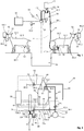
- a milking installation comprises a milk pipeline 10, a plurality of milking locations 12.1, 12.2 each dedicated to an animal 14.1, 14.2, a plurality of milking pipes 16 each comprising at a first end 16.1 a milking cluster 18.
- a pump vacuum 20 creates a vacuum, of the order of - 42 KPa, in the pipeline 10 to cause a flow of milk from each milking cluster 18 to a storage tank 22 via the pipeline 10.
- a pulsator is provided to generate a sequential movement at the sleeves of the milking clusters 18. Consequently, the milk flows through the milking pipes 16 intermittently, in a jerky fashion.
- the pipeline 10 comprises a nozzle 24 intended for each milking pipe 16.
- the milking installation comprises a pit 26 and the milking locations 12.1, 12.1 are distributed equally over two milking zones 28.1, 28.2 arranged on either side of the pit 26.
- An animal 14.1, 14.2 is positioned at each milking location 12.1, 12.2 so that its udder 30 is oriented towards the pit 26 and its head 32 opposite, for example in front of a feeder 34.
- the locations can be provided in the form of a carousel.
- the lactoduct 10 is positioned above the pit 26 and the milking clusters 18.
- the lactoduct 10 is positioned at a height such that it is difficult to reach by an operator positioned in the pit 26.
- the lactoduct 10 is a rigid pipe, positioned horizontally and which extends over the entire length of the milking locations 12.1, 12.1.
- the pipeline has a diameter between 5 and 15 cm.
- the invention is not limited to this positioning for the pipeline.
- each milking pipe 16 is dimensioned so as not to generate too great a pressure drop so as not to alter the milking.
- each milking pipe has an internal diameter between 1 and 3 cm.
- the milking installation comprises as many milking pipes 16 as milking locations 12.1, 12.1.
- the milking installation comprises as many milking pipes 16 as pairs of milking locations 12.1, 12.1, each milking pipe 16 being intended for a first location 12.1 provided at the first milking area 28.1 and for a second location 12.2 provided at the level of the second milking area 28.2.
- the invention is not limited to these two configurations.
- the milk pipeline 10, the vacuum pump 20, the milking pipes 16, the milking clusters 18 are not described any more since they can be identical to those of the prior art milking installations.
- the milking installation comprises at least one individualized control device 36.
- the milking installation comprises an individualized control device 36 for each milking pipe 16.
- the milk of each animal is checked before being mixed with the milk of other animals.
- Each individualized control device 36 comprises a buffer tank 38, a weighing system 40 from which the buffer tank 38 is suspended, a connection pipe 42, in which air and possibly foam flows, which has a first end 42.1 connected to the pipeline 10 and a second end 42.2 opening into the upper part of the buffer tank 38.
- the milking pipe 16 has a second end 16.2 which opens out upper part of the buffer tank 38 while being connected to a nozzle positioned in the upper part of the buffer tank 38.
- the connecting pipe 42 has the same passage section as the milking pipe 16.
- the individualized control device 36 does not alter the milking and does not modify the vacuum created at each milking cluster.
- the first end 42.1 of the connection pipe 42 is connected to the pipeline 10 via the tap 24.
- connection pipe 42 and the milking pipe 16 are connected to the upper part of the buffer tank 38, at an area close to the weighing system 40, makes it possible to limit the impact of the jolts produced during the milking on the measurement of the weight of the milk, making possible the continuous weighing operation, when milking the animal.
- the buffer tank 38 has a central cylindrical body 44.0, closed at each of its upper and lower ends by upper and lower domes 44.1, 44.2.
- the buffer tank 38 has a volume less than or equal to 5 L, preferably between 3.5 and 5L, which corresponds to a maximum volume of milk from the milking of a sheep or a goat.
- the lower dome 44.2 is positioned at a higher height than the pipeline 10.
- the upper dome 44.1 has first and second nozzles 46, 46 'to which the second ends 16.2, 42.2 of the milking pipe 16 and the connecting pipe 42 are connected respectively.
- the milking installation comprises at least one support beam 47 positioned above the pipeline 10, the weighing systems 40 of the individualized control devices 36 being fixed to the support beam 47.
- the support beam 47 extends over the entire length of the milking installation.
- the support beam 47 is made in one piece over its entire length.
- the support beam 47 comprises several sections assembled end-to-end.
- the support beam 47 is connected to a frame or to a building only at each of its ends or it can be suspended at at least one point in addition to being connected to a frame or to a building at each of its ends. extremities.
- the support beam 47 must be as rigid as possible in order to isolate each individualized control device 36 from the vibrations generated by the rest of the milking installation, in particular during milking.
- the weighing system 40 is a force sensor which has a hook 48 to which the buffer tank 38 is suspended. To this end, three links 50.1, 50.2, 50.3, such as for example chains, connect the upper dome 44.1 and the hook 48. The anchoring points of these three links 50.1, 50.2, 50.3 are regularly distributed around the periphery of the upper dome 44.1. Thus, the weighing system 40 is connected to the upper part of the buffer tank 38.
- the weighing system 40 is configured to emit an electrical signal 52 as a function of the weight of the buffer tank 38 more or less filled with milk.
- the weighing system 40 allows continuous or almost continuous measurement of milk during the milking of the animal.
- the individualized control device 36 also comprises a drain pipe 54 which has a first end 54.1 connected to the pipeline 10 and a second end 54.2 opening into the lower part of the buffer tank 38.
- the first end 54.1 of the drain pipe is connected to the first end 42.1 of the connection pipe 42, the first ends 54.1 and 42.1 being connected to the pipeline 10 by means of a common section 102.
- the lower dome 44.2 comprises a nozzle 56 at its lowest point to allow optimal emptying of the buffer tank 38.
- connection 24 of the pipeline 10 comprises a T-connector 58 which has a first end connected to the connection 24, a second end connected to the first end 42.1 of the connection pipe 42 and a third end connected to the first end 54.1 of the connection pipe drain 54.
- the individualized control device 36 comprises a first valve (or solenoid valve) 60, at the level of the drain pipe 54, configured to occupy a blocked state in which it prevents a flow of fluid in the drain pipe 54 and a passing state in which it allows a flow of fluid in the drain pipe 54, in particular at the time of the emptying of the buffer tank 38.
- the individualized control device comprises a second valve 62, for stopping milking, configured to occupy a blocked state in which it prevents a flow of fluid between the milking cluster 18 and the pipeline 10 and a passing state in which it allows a flow of fluid from the milking cluster 18 to the milk pipeline 10.
- the second valve 62 is positioned at the level of the connection pipe 42.
- the second valve 62 is in the form of a jack which has a rod movable in translation configured to crush the pipe in the blocked state and not to crush it in the on state.
- the second valve 62 is positioned so that the pinching area of the connection pipe 42 is located at or near the highest part of the connection pipe 42.
- the pipeline 10 generates a vacuum inside the buffer tank 38 during milking, as long as the second valve 62 is in the on state and no longer generates vacuum inside the buffer tank 38 when milking is finished and that the second valve 62 is in the blocked state.
- the first and second valves 60, 62 can be of pneumatic, hydraulic, electric or other type.
- the operating principle of the individualized control device 36 is as follows.
- the first valve 60 is in the blocked state and the second valve 62 in the on state.
- the buffer tank 38 fills with milk.
- the weight of the milk is measured in real time by the weighing system 40. Knowing the time between two measurements, it is then possible to determine the flow of milk.
- the weight of the milk is measured at the end milking, especially when the second valve 62 is in the blocked state. In this case, it is possible to take several measurements in a short period of time and to average the measurements.
- the two operating modes namely use the first operating mode to stop the milking by switching the second valve 62 to the blocked state, when the calculated flow rate drops below a given threshold, then use the second mode of operation, after stopping milking to determine the weight of the milk precisely.
- the first valve 60 remains in the blocked state, after the milking has stopped, during the phase of determining the weight of the milk.
- the first valve 60 is switched to the on state. From then on, the milk flows from the buffer tank 38 to the milk pipeline 10 via the drain pipe 54. After the draining, to start a new cycle, the first valve 60 is switched to the blocked state and the second valve 62 to l passing state.
- the individualized control device 36 comprises a venting system configured to occupy a blocked state in which the buffer tank 38 is isolated from the exterior of the buffer tank or of an air intake and a passing state in which the tank 38 communicates with the outside of the buffer tank or an air intake.
- This venting system is relatively important because it makes it possible to detach the milking cluster 18 from the animal after milking.
- the venting system is positioned in the upper part of the buffer tank 38.
- the upper dome 44.1 of the buffer tank 38 comprises a nozzle to which is connected the first end 64.1 of the exhaust pipe 64.
- the third valve 66 is in the on state during emptying and remains in the blocked state the rest of the time.
- line 10 is positioned in below the nozzle 56 of the lower dome 44.2 so that the milk flows by gravity from the buffer tank 38 to the milk pipeline 10.
- the venting system comprises an opening in the upper part of the buffer tank 38 as well as a solenoid plunger assembly 104 configured to occupy a first blocked state in which the plunger closes the opening when the solenoid is not supplied in electric current and a second passing state in which the plunger does not close the opening when the solenoid is supplied with electric current.
- the interior of the buffer tank 38 communicates via the opening with the exterior.
- the buffer tank 38 comprises at least one sensor configured to measure or evaluate at least one characteristic of the milk temporarily stored in the buffer tank 38.
- the buffer tank 38 comprises a temperature sensor 68 and / or a sensor for measuring the conductivity of the milk 70.
- the invention is not limited to these sensors. Others could be planned.
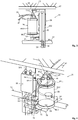
- the individualized control device 36 comprises a sampling system making it possible to take a sample of milk temporarily stored in the buffer tank 38.
- the sampling system comprises a sampling pipe 72 having a first end connected to the buffer tank 38 and a second free end as well as a fourth valve 74 configured to occupy a passing state in which it allows a flow of milk from the buffer tank 38 to the second end of the sampling pipe 72 and a blocked state in which it prevents a flow of milk from the buffer tank 38 to the second end of the sampling pipe 72.
- connection 56 of the lower dome 44.2 comprises a T-connector 76 which has a first end connected to the nozzle 56, a second end connected to the first end 54.1 of the drain pipe 54 and a third end connected to a first end 72a.1 of a first section 72a of the sampling pipe 72, the second end 72a.2 of the first section 72a of the sampling pipe 72 being connected to the fourth valve 74.
- the sampling pipe 72 comprises a second section 72b, downstream of the fourth valve 74, which has a first end 72b.1 connected to the fourth valve 74 and a second free end 72b.2 through which the sampled milk flows.
- the second section 72b is approximately vertical. It must be as short as possible so that the milk does not stagnate inside the second section 72b between two withdrawals.
- the second section 72b must be less than or equal to 5 cm in length.
- the first section 72a of the sampling pipe 72 positioned between the buffer tank 38 and the fourth valve 74, is approximately horizontal or inclined towards the first end 72a.1, in the direction of the drainage pipe 54, so as to avoid that milk does not stagnate in the first section 72a after the emptying of the buffer tank 38.
- the collection system also includes at least one cup 78 into which the milk collected is poured.
- the sampling system comprises as many cups 78 as there are samples to be taken.
- the collection system also includes a cup holder 80 allowing the cup 78 to be held under the second free end of the collection pipe 72 so that the milk collected flows out of the second end of the collection pipe 72 into the cup 78 positioned on the cup holder 80.
- the cup support 80 is movable vertically to allow an operator positioned in the pit 26 to grasp the cup 80, while having a second section 72b for the shortest sampling pipe 72 possible. to prevent milk from stagnating in said second section 72b after the closing of the fourth valve 74.
- the sampling system comprises a jack 82, integral with a frame 100 connected to the support beam 47, which has a rod 84 which is vertically translate between a retracted position in which the cup support 80 is positioned in the high position just under the second section 72b of the sampling pipe 72 and an extended position in which the cup support 80 is positioned in the low position so as to allow an operator to grasp the cup 78 easily.
- the invention is not limited to a jack for obtaining the vertical movement of the cup support 80.
- the cup holder 80 is configured so as to keep the cup 78 vertical, in particular during the removal and movements of the cup between the high position and the low position. It must also be configured to allow an operator to easily remove the cup 78 present on the cup support 80 and to reposition a new cup 78 on the cup support 80 when the latter is in the low position.
- the sampling system works as follows. At the end of the milking, when the milking is stopped and the vacuum pump 20 no longer generates vacuum inside the buffer tank 38, the fourth valve 74 is switched to the on state. By gravity, the milk flows from the buffer tank 38 into the cup 78 via the sampling pipe 72. If necessary, to facilitate the flow of milk, the third valve 66 is switched to the on state.
- the third and fourth valves 66, 74 are repositioned in the locked position.
- the fourth valve 74 can be opened.
- the air enters the buffer tank 38 via the sampling pipe 72 and generates inside the buffer tank 38 a brewing the milk in order to homogenize it to obtain more reliable measurements.
- the individualized control device 36 includes a system for identifying each sample.
- the cup 78 includes a unique identifier which is specific to it.
- each cup 78 comprises a cup marker 86 of the RFID type, in which the identifier of the cup 78 is stored and the individualized control device 36 comprises a first marker reader cup 88 positioned near the cup support 80 when the latter is in the high position.
- each animal 14.1, 14.2 has an animal marker 92, for example fixed at one of its ears.
- the milking installation includes at least one animal marker reader 94.1, 94.2 configured to identify the animal from each location.
- the milking installation includes a marker reader 94.1, 94.2 for each row of locations which is configured to scroll in line with each location in the row, along a rail 96.1, 96.2 near each feeder 34.
- the individualized control device comprises an automaton 98 configured to control the four valves 60, 62, 66, 74 and which is informed by the weighing system 40, by the sensor (s) 68, 70 equipping the buffer tank 78 and by the positioning sensors 90.1, 90.2 and the marker readers 88, 94.1, 94.2.
- An automatic device can be provided for each individualized control device or an automatic device can be provided for several individualized control devices. According to one configuration, a first automaton can be provided for all of the individualized control devices and a second automaton for each individualized control device.
- existing commands such as the stall system commands 106 for example, can be coupled to the machine 98 and used for example to switch the second valve 62 in the blocked state in order to stop milking.
- the milking installation includes at least one screen in order to display at least certain measures or information for each animal being milked.
- This screen can optionally be used to select the locations at which a sample is to be taken or to stop milking.
- the milking of each animal can be stopped individually, autonomously and automatically, by the machine 98 which can switch, from the measurements of the weight of the milk, the second valve 62 to the blocked state when the change in weight drops below a certain threshold or when the milk flow drops below a given threshold, the milk flow being calculated by the machine 98 from the measurements of the weight of the milk given by the weighing system 40.
- the operator is informed at the time of milking if the milk of an animal has an abnormality.
- the operator can act accordingly by taking the most appropriate measure, for example by initiating the taking of a sample for the animal concerned or by not mixing the milk of this animal with the others.
- the automaton 98 is configured to compare the characteristic (s) measured with at least one predefined criterion and issue a signal or information if the (or the) characteristic (s) measured does not (or are not) compliant (s) with the predefined criterion (s).
- the machine 98 is configured to store, in at least one database, for each animal, the animal identifier, the weight of the milk present in the buffer tank 38 at the end of the milking of the animal.
- the individualized control devices facilitate the establishment of a monitoring of the daily milk production of each animal. Thanks to the measurements of the conductivity of the milk and the temperature of the milk for each animal, we obtain regular monitoring of the state of health of each animal.
- the machine 98 can also associate, for each sample stored in a cup 78, the identifier of the cup 78, the identifier of the animal, the weight of the milk present in the buffer tank after milking the animal, milk conductivity, milk temperature.
- the individualized control device makes it possible to establish an effective traceability of the milk of each animal.
Landscapes
- Life Sciences & Earth Sciences (AREA)
- Animal Husbandry (AREA)
- Environmental Sciences (AREA)
- Dairy Products (AREA)
- Sampling And Sample Adjustment (AREA)
Applications Claiming Priority (1)
| Application Number | Priority Date | Filing Date | Title |
|---|---|---|---|
| FR1859607A FR3087315B1 (fr) | 2018-10-17 | 2018-10-17 | Dispositif de controle individualise du lait pour une installation de traite et installation de traite equipee de plusieurs dispositifs de controle individualise |
Publications (2)
| Publication Number | Publication Date |
|---|---|
| EP3639655A1 true EP3639655A1 (de) | 2020-04-22 |
| EP3639655B1 EP3639655B1 (de) | 2021-08-11 |
Family
ID=65244317
Family Applications (1)
| Application Number | Title | Priority Date | Filing Date |
|---|---|---|---|
| EP19202297.8A Active EP3639655B1 (de) | 2018-10-17 | 2019-10-09 | Vereinzelte milchkontrollvorrichtung für eine melkanlage, und mit mehreren solchen vereinzelten kontrollvorrichtungen ausgestattete melkanlage |
Country Status (2)
| Country | Link |
|---|---|
| EP (1) | EP3639655B1 (de) |
| FR (1) | FR3087315B1 (de) |
Citations (4)
| Publication number | Priority date | Publication date | Assignee | Title |
|---|---|---|---|---|
| US2808025A (en) | 1951-11-20 | 1957-10-01 | Graves Stambaugh Corp | Milking and collecting apparatus |
| GB1512807A (en) * | 1974-08-02 | 1978-06-01 | Jansky Tank & App | Apparatus for the measurement of a volume of milk |
| US4548161A (en) * | 1983-08-08 | 1985-10-22 | Germania Dairy Automation, Inc. | Milk weight metering method and apparatus |
| WO2015170974A1 (en) * | 2014-05-09 | 2015-11-12 | Lely Patent N.V. | Milk tank system, intermediate milk storage vessel for this, milking system for this, and method for cleaning this |
Family Cites Families (3)
| Publication number | Priority date | Publication date | Assignee | Title |
|---|---|---|---|---|
| AU466506B2 (en) * | 1971-05-10 | 1975-10-30 | Stephen Grochowicz Peter | Method and apparatus for miix production analysis |
| DE29723985U1 (de) * | 1996-03-29 | 1999-07-08 | Maasland N.V., Maasland | Vorrichtung zum Melken von Tieren |
| DE102016121795A1 (de) * | 2016-11-14 | 2018-05-17 | Impulsa Ag | Milchmengenmessvorrichtung |
-
2018
- 2018-10-17 FR FR1859607A patent/FR3087315B1/fr not_active Expired - Fee Related
-
2019
- 2019-10-09 EP EP19202297.8A patent/EP3639655B1/de active Active
Patent Citations (4)
| Publication number | Priority date | Publication date | Assignee | Title |
|---|---|---|---|---|
| US2808025A (en) | 1951-11-20 | 1957-10-01 | Graves Stambaugh Corp | Milking and collecting apparatus |
| GB1512807A (en) * | 1974-08-02 | 1978-06-01 | Jansky Tank & App | Apparatus for the measurement of a volume of milk |
| US4548161A (en) * | 1983-08-08 | 1985-10-22 | Germania Dairy Automation, Inc. | Milk weight metering method and apparatus |
| WO2015170974A1 (en) * | 2014-05-09 | 2015-11-12 | Lely Patent N.V. | Milk tank system, intermediate milk storage vessel for this, milking system for this, and method for cleaning this |
Also Published As
| Publication number | Publication date |
|---|---|
| FR3087315A1 (fr) | 2020-04-24 |
| FR3087315B1 (fr) | 2020-10-09 |
| EP3639655B1 (de) | 2021-08-11 |
Similar Documents
| Publication | Publication Date | Title |
|---|---|---|
| EP0306579B1 (de) | Automatische Melkmaschine | |
| EP2194773B1 (de) | Melkanlage und verfahren zur reinigung einer melkanlage | |
| EP0385539B1 (de) | Melkanlage | |
| EP2632247B1 (de) | Steuersystem und verfahren für melkeinheiten eines melkstandes | |
| US10617093B2 (en) | Milking device | |
| EP1039796B2 (de) | Verfahren und vorrichtung zum abtrennen von vormilch | |
| WO2000074472A1 (en) | Method and device for the automatic milking of animals in milking positions which move in a revolving path | |
| US3957018A (en) | Milking apparatus | |
| CA2944321C (en) | Milk tank system, intermediate milk storage vessel for this, milking system for this, and method for cleaning this | |
| EP3639655B1 (de) | Vereinzelte milchkontrollvorrichtung für eine melkanlage, und mit mehreren solchen vereinzelten kontrollvorrichtungen ausgestattete melkanlage | |
| CA2946871C (en) | Milking device | |
| JP2007267734A (ja) | 適応搾乳システム | |
| KR102163580B1 (ko) | 가축용 자동착유장치 | |
| NZ286848A (en) | Milk sampling device with filling member moved stepwise past containers in removable cassette by guide being raised and lowered | |
| WO2008037882A2 (fr) | Systeme d'abreuvement automatique intermittent programme | |
| EP2477479B1 (de) | Anordnung und verfahren zur anzeige einer ungewünschten ablösung eines melkelements von einem tier | |
| CN221883147U (zh) | 一种在挤奶机上安装的在线原奶分群自动化采样装置 | |
| CN103910184A (zh) | 母猪饲料传输线的自动控制装置及控制方法 | |
| NL1014846C2 (nl) | Werkwijze en inrichting voor het melken van dieren. | |
| Goldsmith | Automatic Teatcup Cluster Removal | |
| FR2756141A1 (fr) | Dispositif entierement automatique pour identifier les vaches en chaleurs | |
| PL224566B1 (pl) | Układ do kontroli działania urządzenia do automatycznego zdejmowania aparatu udojowego | |
| WO2018019819A1 (fr) | Installation de traite avec lisse avant montante et basculante | |
| WO1983001558A1 (fr) | Dispositif automatique de distribution de liquide applique notamment a l'irrigation | |
| FR2899433A1 (fr) | Dispositif d'abreuvement de volailles, en particulier de palmipedes, comprenant des distributeurs individuels surmontant des moyens de recuperation, et installation correspondant |
Legal Events
| Date | Code | Title | Description |
|---|---|---|---|
| PUAI | Public reference made under article 153(3) epc to a published international application that has entered the european phase |
Free format text: ORIGINAL CODE: 0009012 |
|
| STAA | Information on the status of an ep patent application or granted ep patent |
Free format text: STATUS: THE APPLICATION HAS BEEN PUBLISHED |
|
| AK | Designated contracting states |
Kind code of ref document: A1 Designated state(s): AL AT BE BG CH CY CZ DE DK EE ES FI FR GB GR HR HU IE IS IT LI LT LU LV MC MK MT NL NO PL PT RO RS SE SI SK SM TR |
|
| AX | Request for extension of the european patent |
Extension state: BA ME |
|
| STAA | Information on the status of an ep patent application or granted ep patent |
Free format text: STATUS: REQUEST FOR EXAMINATION WAS MADE |
|
| 17P | Request for examination filed |
Effective date: 20200925 |
|
| RBV | Designated contracting states (corrected) |
Designated state(s): AL AT BE BG CH CY CZ DE DK EE ES FI FR GB GR HR HU IE IS IT LI LT LU LV MC MK MT NL NO PL PT RO RS SE SI SK SM TR |
|
| GRAP | Despatch of communication of intention to grant a patent |
Free format text: ORIGINAL CODE: EPIDOSNIGR1 |
|
| STAA | Information on the status of an ep patent application or granted ep patent |
Free format text: STATUS: GRANT OF PATENT IS INTENDED |
|
| INTG | Intention to grant announced |
Effective date: 20210316 |
|
| GRAS | Grant fee paid |
Free format text: ORIGINAL CODE: EPIDOSNIGR3 |
|
| GRAA | (expected) grant |
Free format text: ORIGINAL CODE: 0009210 |
|
| STAA | Information on the status of an ep patent application or granted ep patent |
Free format text: STATUS: THE PATENT HAS BEEN GRANTED |
|
| AK | Designated contracting states |
Kind code of ref document: B1 Designated state(s): AL AT BE BG CH CY CZ DE DK EE ES FI FR GB GR HR HU IE IS IT LI LT LU LV MC MK MT NL NO PL PT RO RS SE SI SK SM TR |
|
| REG | Reference to a national code |
Ref country code: CH Ref legal event code: EP |
|
| REG | Reference to a national code |
Ref country code: DE Ref legal event code: R096 Ref document number: 602019006770 Country of ref document: DE |
|
| REG | Reference to a national code |
Ref country code: IE Ref legal event code: FG4D Free format text: LANGUAGE OF EP DOCUMENT: FRENCH Ref country code: AT Ref legal event code: REF Ref document number: 1418430 Country of ref document: AT Kind code of ref document: T Effective date: 20210915 |
|
| REG | Reference to a national code |
Ref country code: LT Ref legal event code: MG9D |
|
| REG | Reference to a national code |
Ref country code: NL Ref legal event code: MP Effective date: 20210811 |
|
| REG | Reference to a national code |
Ref country code: AT Ref legal event code: MK05 Ref document number: 1418430 Country of ref document: AT Kind code of ref document: T Effective date: 20210811 |
|
| PG25 | Lapsed in a contracting state [announced via postgrant information from national office to epo] |
Ref country code: RS Free format text: LAPSE BECAUSE OF FAILURE TO SUBMIT A TRANSLATION OF THE DESCRIPTION OR TO PAY THE FEE WITHIN THE PRESCRIBED TIME-LIMIT Effective date: 20210811 Ref country code: SE Free format text: LAPSE BECAUSE OF FAILURE TO SUBMIT A TRANSLATION OF THE DESCRIPTION OR TO PAY THE FEE WITHIN THE PRESCRIBED TIME-LIMIT Effective date: 20210811 Ref country code: ES Free format text: LAPSE BECAUSE OF FAILURE TO SUBMIT A TRANSLATION OF THE DESCRIPTION OR TO PAY THE FEE WITHIN THE PRESCRIBED TIME-LIMIT Effective date: 20210811 Ref country code: LT Free format text: LAPSE BECAUSE OF FAILURE TO SUBMIT A TRANSLATION OF THE DESCRIPTION OR TO PAY THE FEE WITHIN THE PRESCRIBED TIME-LIMIT Effective date: 20210811 Ref country code: BG Free format text: LAPSE BECAUSE OF FAILURE TO SUBMIT A TRANSLATION OF THE DESCRIPTION OR TO PAY THE FEE WITHIN THE PRESCRIBED TIME-LIMIT Effective date: 20211111 Ref country code: AT Free format text: LAPSE BECAUSE OF FAILURE TO SUBMIT A TRANSLATION OF THE DESCRIPTION OR TO PAY THE FEE WITHIN THE PRESCRIBED TIME-LIMIT Effective date: 20210811 Ref country code: FI Free format text: LAPSE BECAUSE OF FAILURE TO SUBMIT A TRANSLATION OF THE DESCRIPTION OR TO PAY THE FEE WITHIN THE PRESCRIBED TIME-LIMIT Effective date: 20210811 Ref country code: HR Free format text: LAPSE BECAUSE OF FAILURE TO SUBMIT A TRANSLATION OF THE DESCRIPTION OR TO PAY THE FEE WITHIN THE PRESCRIBED TIME-LIMIT Effective date: 20210811 Ref country code: PT Free format text: LAPSE BECAUSE OF FAILURE TO SUBMIT A TRANSLATION OF THE DESCRIPTION OR TO PAY THE FEE WITHIN THE PRESCRIBED TIME-LIMIT Effective date: 20211213 Ref country code: NO Free format text: LAPSE BECAUSE OF FAILURE TO SUBMIT A TRANSLATION OF THE DESCRIPTION OR TO PAY THE FEE WITHIN THE PRESCRIBED TIME-LIMIT Effective date: 20211111 |
|
| PG25 | Lapsed in a contracting state [announced via postgrant information from national office to epo] |
Ref country code: PL Free format text: LAPSE BECAUSE OF FAILURE TO SUBMIT A TRANSLATION OF THE DESCRIPTION OR TO PAY THE FEE WITHIN THE PRESCRIBED TIME-LIMIT Effective date: 20210811 Ref country code: LV Free format text: LAPSE BECAUSE OF FAILURE TO SUBMIT A TRANSLATION OF THE DESCRIPTION OR TO PAY THE FEE WITHIN THE PRESCRIBED TIME-LIMIT Effective date: 20210811 Ref country code: GR Free format text: LAPSE BECAUSE OF FAILURE TO SUBMIT A TRANSLATION OF THE DESCRIPTION OR TO PAY THE FEE WITHIN THE PRESCRIBED TIME-LIMIT Effective date: 20211112 |
|
| PG25 | Lapsed in a contracting state [announced via postgrant information from national office to epo] |
Ref country code: NL Free format text: LAPSE BECAUSE OF FAILURE TO SUBMIT A TRANSLATION OF THE DESCRIPTION OR TO PAY THE FEE WITHIN THE PRESCRIBED TIME-LIMIT Effective date: 20210811 |
|
| PG25 | Lapsed in a contracting state [announced via postgrant information from national office to epo] |
Ref country code: DK Free format text: LAPSE BECAUSE OF FAILURE TO SUBMIT A TRANSLATION OF THE DESCRIPTION OR TO PAY THE FEE WITHIN THE PRESCRIBED TIME-LIMIT Effective date: 20210811 |
|
| REG | Reference to a national code |
Ref country code: DE Ref legal event code: R119 Ref document number: 602019006770 Country of ref document: DE |
|
| PG25 | Lapsed in a contracting state [announced via postgrant information from national office to epo] |
Ref country code: SM Free format text: LAPSE BECAUSE OF FAILURE TO SUBMIT A TRANSLATION OF THE DESCRIPTION OR TO PAY THE FEE WITHIN THE PRESCRIBED TIME-LIMIT Effective date: 20210811 Ref country code: SK Free format text: LAPSE BECAUSE OF FAILURE TO SUBMIT A TRANSLATION OF THE DESCRIPTION OR TO PAY THE FEE WITHIN THE PRESCRIBED TIME-LIMIT Effective date: 20210811 Ref country code: RO Free format text: LAPSE BECAUSE OF FAILURE TO SUBMIT A TRANSLATION OF THE DESCRIPTION OR TO PAY THE FEE WITHIN THE PRESCRIBED TIME-LIMIT Effective date: 20210811 Ref country code: EE Free format text: LAPSE BECAUSE OF FAILURE TO SUBMIT A TRANSLATION OF THE DESCRIPTION OR TO PAY THE FEE WITHIN THE PRESCRIBED TIME-LIMIT Effective date: 20210811 Ref country code: CZ Free format text: LAPSE BECAUSE OF FAILURE TO SUBMIT A TRANSLATION OF THE DESCRIPTION OR TO PAY THE FEE WITHIN THE PRESCRIBED TIME-LIMIT Effective date: 20210811 Ref country code: AL Free format text: LAPSE BECAUSE OF FAILURE TO SUBMIT A TRANSLATION OF THE DESCRIPTION OR TO PAY THE FEE WITHIN THE PRESCRIBED TIME-LIMIT Effective date: 20210811 |
|
| PLBE | No opposition filed within time limit |
Free format text: ORIGINAL CODE: 0009261 |
|
| STAA | Information on the status of an ep patent application or granted ep patent |
Free format text: STATUS: NO OPPOSITION FILED WITHIN TIME LIMIT |
|
| REG | Reference to a national code |
Ref country code: BE Ref legal event code: MM Effective date: 20211031 |
|
| PG25 | Lapsed in a contracting state [announced via postgrant information from national office to epo] |
Ref country code: MC Free format text: LAPSE BECAUSE OF FAILURE TO SUBMIT A TRANSLATION OF THE DESCRIPTION OR TO PAY THE FEE WITHIN THE PRESCRIBED TIME-LIMIT Effective date: 20210811 |
|
| 26N | No opposition filed |
Effective date: 20220512 |
|
| PG25 | Lapsed in a contracting state [announced via postgrant information from national office to epo] |
Ref country code: LU Free format text: LAPSE BECAUSE OF NON-PAYMENT OF DUE FEES Effective date: 20211009 Ref country code: IT Free format text: LAPSE BECAUSE OF FAILURE TO SUBMIT A TRANSLATION OF THE DESCRIPTION OR TO PAY THE FEE WITHIN THE PRESCRIBED TIME-LIMIT Effective date: 20210811 Ref country code: DE Free format text: LAPSE BECAUSE OF NON-PAYMENT OF DUE FEES Effective date: 20220503 Ref country code: BE Free format text: LAPSE BECAUSE OF NON-PAYMENT OF DUE FEES Effective date: 20211031 |
|
| PG25 | Lapsed in a contracting state [announced via postgrant information from national office to epo] |
Ref country code: SI Free format text: LAPSE BECAUSE OF FAILURE TO SUBMIT A TRANSLATION OF THE DESCRIPTION OR TO PAY THE FEE WITHIN THE PRESCRIBED TIME-LIMIT Effective date: 20210811 |
|
| PG25 | Lapsed in a contracting state [announced via postgrant information from national office to epo] |
Ref country code: IE Free format text: LAPSE BECAUSE OF NON-PAYMENT OF DUE FEES Effective date: 20211009 |
|
| REG | Reference to a national code |
Ref country code: CH Ref legal event code: PL |
|
| PG25 | Lapsed in a contracting state [announced via postgrant information from national office to epo] |
Ref country code: CY Free format text: LAPSE BECAUSE OF FAILURE TO SUBMIT A TRANSLATION OF THE DESCRIPTION OR TO PAY THE FEE WITHIN THE PRESCRIBED TIME-LIMIT Effective date: 20210811 |
|
| PG25 | Lapsed in a contracting state [announced via postgrant information from national office to epo] |
Ref country code: LI Free format text: LAPSE BECAUSE OF NON-PAYMENT OF DUE FEES Effective date: 20221031 Ref country code: HU Free format text: LAPSE BECAUSE OF FAILURE TO SUBMIT A TRANSLATION OF THE DESCRIPTION OR TO PAY THE FEE WITHIN THE PRESCRIBED TIME-LIMIT; INVALID AB INITIO Effective date: 20191009 Ref country code: CH Free format text: LAPSE BECAUSE OF NON-PAYMENT OF DUE FEES Effective date: 20221031 |
|
| PG25 | Lapsed in a contracting state [announced via postgrant information from national office to epo] |
Ref country code: MK Free format text: LAPSE BECAUSE OF FAILURE TO SUBMIT A TRANSLATION OF THE DESCRIPTION OR TO PAY THE FEE WITHIN THE PRESCRIBED TIME-LIMIT Effective date: 20210811 |
|
| GBPC | Gb: european patent ceased through non-payment of renewal fee |
Effective date: 20231009 |
|
| PG25 | Lapsed in a contracting state [announced via postgrant information from national office to epo] |
Ref country code: GB Free format text: LAPSE BECAUSE OF NON-PAYMENT OF DUE FEES Effective date: 20231009 |
|
| PG25 | Lapsed in a contracting state [announced via postgrant information from national office to epo] |
Ref country code: GB Free format text: LAPSE BECAUSE OF NON-PAYMENT OF DUE FEES Effective date: 20231009 |
|
| PG25 | Lapsed in a contracting state [announced via postgrant information from national office to epo] |
Ref country code: MT Free format text: LAPSE BECAUSE OF FAILURE TO SUBMIT A TRANSLATION OF THE DESCRIPTION OR TO PAY THE FEE WITHIN THE PRESCRIBED TIME-LIMIT Effective date: 20210811 |
|
| PG25 | Lapsed in a contracting state [announced via postgrant information from national office to epo] |
Ref country code: TR Free format text: LAPSE BECAUSE OF FAILURE TO SUBMIT A TRANSLATION OF THE DESCRIPTION OR TO PAY THE FEE WITHIN THE PRESCRIBED TIME-LIMIT Effective date: 20210811 |
|
| PGFP | Annual fee paid to national office [announced via postgrant information from national office to epo] |
Ref country code: FR Payment date: 20251021 Year of fee payment: 7 |