EP3639014B1 - Fasergekoppelte breitbandlichtquelle - Google Patents
Fasergekoppelte breitbandlichtquelle Download PDFInfo
- Publication number
- EP3639014B1 EP3639014B1 EP18817970.9A EP18817970A EP3639014B1 EP 3639014 B1 EP3639014 B1 EP 3639014B1 EP 18817970 A EP18817970 A EP 18817970A EP 3639014 B1 EP3639014 B1 EP 3639014B1
- Authority
- EP
- European Patent Office
- Prior art keywords
- optical
- fluorophores
- qds
- optical element
- fiber
- Prior art date
- Legal status (The legal status is an assumption and is not a legal conclusion. Google has not performed a legal analysis and makes no representation as to the accuracy of the status listed.)
- Active
Links
Images


Classifications
-
- A—HUMAN NECESSITIES
- A61—MEDICAL OR VETERINARY SCIENCE; HYGIENE
- A61B—DIAGNOSIS; SURGERY; IDENTIFICATION
- A61B5/00—Measuring for diagnostic purposes; Identification of persons
- A61B5/0059—Measuring for diagnostic purposes; Identification of persons using light, e.g. diagnosis by transillumination, diascopy, fluorescence
- A61B5/0071—Measuring for diagnostic purposes; Identification of persons using light, e.g. diagnosis by transillumination, diascopy, fluorescence by measuring fluorescence emission
-
- G—PHYSICS
- G01—MEASURING; TESTING
- G01J—MEASUREMENT OF INTENSITY, VELOCITY, SPECTRAL CONTENT, POLARISATION, PHASE OR PULSE CHARACTERISTICS OF INFRARED, VISIBLE OR ULTRAVIOLET LIGHT; COLORIMETRY; RADIATION PYROMETRY
- G01J3/00—Spectrometry; Spectrophotometry; Monochromators; Measuring colours
- G01J3/02—Details
- G01J3/0205—Optical elements not provided otherwise, e.g. optical manifolds, diffusers, windows
- G01J3/0218—Optical elements not provided otherwise, e.g. optical manifolds, diffusers, windows using optical fibers
-
- A—HUMAN NECESSITIES
- A61—MEDICAL OR VETERINARY SCIENCE; HYGIENE
- A61B—DIAGNOSIS; SURGERY; IDENTIFICATION
- A61B5/00—Measuring for diagnostic purposes; Identification of persons
- A61B5/0059—Measuring for diagnostic purposes; Identification of persons using light, e.g. diagnosis by transillumination, diascopy, fluorescence
- A61B5/0075—Measuring for diagnostic purposes; Identification of persons using light, e.g. diagnosis by transillumination, diascopy, fluorescence by spectroscopy, i.e. measuring spectra, e.g. Raman spectroscopy, infrared absorption spectroscopy
-
- G—PHYSICS
- G01—MEASURING; TESTING
- G01J—MEASUREMENT OF INTENSITY, VELOCITY, SPECTRAL CONTENT, POLARISATION, PHASE OR PULSE CHARACTERISTICS OF INFRARED, VISIBLE OR ULTRAVIOLET LIGHT; COLORIMETRY; RADIATION PYROMETRY
- G01J3/00—Spectrometry; Spectrophotometry; Monochromators; Measuring colours
- G01J3/02—Details
- G01J3/10—Arrangements of light sources specially adapted for spectrometry or colorimetry
- G01J3/108—Arrangements of light sources specially adapted for spectrometry or colorimetry for measurement in the infrared range
-
- G—PHYSICS
- G01—MEASURING; TESTING
- G01J—MEASUREMENT OF INTENSITY, VELOCITY, SPECTRAL CONTENT, POLARISATION, PHASE OR PULSE CHARACTERISTICS OF INFRARED, VISIBLE OR ULTRAVIOLET LIGHT; COLORIMETRY; RADIATION PYROMETRY
- G01J3/00—Spectrometry; Spectrophotometry; Monochromators; Measuring colours
- G01J3/28—Investigating the spectrum
- G01J3/42—Absorption spectrometry; Double beam spectrometry; Flicker spectrometry; Reflection spectrometry
-
- G—PHYSICS
- G02—OPTICS
- G02B—OPTICAL ELEMENTS, SYSTEMS OR APPARATUS
- G02B6/00—Light guides; Structural details of arrangements comprising light guides and other optical elements, e.g. couplings
- G02B6/0001—Light guides; Structural details of arrangements comprising light guides and other optical elements, e.g. couplings specially adapted for lighting devices or systems
- G02B6/0003—Light guides; Structural details of arrangements comprising light guides and other optical elements, e.g. couplings specially adapted for lighting devices or systems the light guides being doped with fluorescent agents
-
- A—HUMAN NECESSITIES
- A61—MEDICAL OR VETERINARY SCIENCE; HYGIENE
- A61B—DIAGNOSIS; SURGERY; IDENTIFICATION
- A61B2562/00—Details of sensors; Constructional details of sensor housings or probes; Accessories for sensors
- A61B2562/02—Details of sensors specially adapted for in-vivo measurements
- A61B2562/0233—Special features of optical sensors or probes classified in A61B5/00
-
- G—PHYSICS
- G01—MEASURING; TESTING
- G01J—MEASUREMENT OF INTENSITY, VELOCITY, SPECTRAL CONTENT, POLARISATION, PHASE OR PULSE CHARACTERISTICS OF INFRARED, VISIBLE OR ULTRAVIOLET LIGHT; COLORIMETRY; RADIATION PYROMETRY
- G01J3/00—Spectrometry; Spectrophotometry; Monochromators; Measuring colours
- G01J3/02—Details
- G01J3/10—Arrangements of light sources specially adapted for spectrometry or colorimetry
-
- G—PHYSICS
- G02—OPTICS
- G02B—OPTICAL ELEMENTS, SYSTEMS OR APPARATUS
- G02B6/00—Light guides; Structural details of arrangements comprising light guides and other optical elements, e.g. couplings
- G02B6/0001—Light guides; Structural details of arrangements comprising light guides and other optical elements, e.g. couplings specially adapted for lighting devices or systems
- G02B6/0005—Light guides; Structural details of arrangements comprising light guides and other optical elements, e.g. couplings specially adapted for lighting devices or systems the light guides being of the fibre type
- G02B6/0008—Light guides; Structural details of arrangements comprising light guides and other optical elements, e.g. couplings specially adapted for lighting devices or systems the light guides being of the fibre type the light being emitted at the end of the fibre
-
- G—PHYSICS
- G02—OPTICS
- G02B—OPTICAL ELEMENTS, SYSTEMS OR APPARATUS
- G02B6/00—Light guides; Structural details of arrangements comprising light guides and other optical elements, e.g. couplings
- G02B6/24—Coupling light guides
- G02B6/42—Coupling light guides with opto-electronic elements
- G02B6/4296—Coupling light guides with opto-electronic elements coupling with sources of high radiant energy, e.g. high power lasers, high temperature light sources
Definitions
- the present disclosure relates generally to down-conversion materials and devices, and more specifically to fluorescent material-coupled fiber optic elements for medical diagnostics.
- STS is widely used as a tool for determining the optical properties of tissues. Such tools are being investigated as an aid for detecting cancers, monitoring changes in tissue optical properties that reflect morphological and physiological changes, and monitoring therapy response (for instance, in photodynamic therapy). Wavelengths up to -1600 nm are actively used to determine concentrations of water and lipid, which have distinct absorption peaks in the near-infrared (NIR) spectral region. Multiple clinical studies have shown that STS can provide information on intrinsic physiological tissue properties, such as oxy- and deoxy-hemoglobin, content of water, and lipids, which can be successfully used to diagnose breast cancer with sensitivity and specificity as high as 100% and 96% respectively.
- NIR near-infrared
- tissue optical index compound function of deoxy-hemoglobin, water and lipid tissue concentration
- US2010/182569A1 shows an opthalmic endoilluminator.
- an optical element which comprises an optical fiber; and a plurality of fluorophores disposed inside said optical fiber; wherein said fluorophores have a quantum yield greater than 50%, wherein said fluorophores emit a spectrum of light having a maximum intensity at wavelengths within the range of 400 nm to 2000 nm.
- a method for performing a spectral tissue sensing (STS) analysis on a subject.
- the method comprises (a) providing an instrument which includes an input source of electromagnetic radiation and an optical element, wherein the optical element comprises an optical fiber and a plurality of fluorophores disposed inside said optical fiber, wherein said fluorophores have a quantum yield greater than 50%, wherein said fluorophores emit a spectrum of light having a maximum intensity at wavelengths within the range of 400 nm to 2000 nm, and wherein said fluorophores emit a spectrum of light having full-width at maximum intensity of greater than 40 nm; (b) generating an output source of electromagnetic radiation by directing electromagnetic radiation from the input source along an optical path that includes the optical element; (c) irradiating a portion of tissue with electromagnetic radiation from the output source; and (d) performing STS analysis on the irradiated tissue.
- STS spectral tissue sensing
- Carcinogen A material that has been shown to directly or indirectly cause cancer in any mammal.
- Fiber Optic A cylindrical shaped waveguide for light.
- the light to be guided can be UV, visible, NIR, or IR.
- the fiber can be made of a polymer or ceramic. Typical fiber optic materials are glass, acrylic polymers, vinyls, ionoplast, and silicones.
- Photoluminescence The emission of light (electromagnetic radiation, photons) after the absorption of light. It is one form of luminescence (light emission) and is initiated by photoexcitation (excitation by photons).
- Toxic Denotes a material that can damage living organisms due to the presence of phosphorus or heavy metals such as cadmium, lead, or mercury.
- Quantum Dot A nanoscale particle that exhibits size-dependent electronic and optical properties due to quantum confinement.
- the quantum dots disclosed herein preferably have at least one dimension less than about 50 nanometers.
- the disclosed quantum dots may be colloidal quantum dots, i.e., quantum dots that may remain in suspension when dispersed in a liquid medium.
- Some of the quantum dots which may be utilized in the compositions, systems and methodologies described herein are made from a binary semiconductor material having a formula MX, where M is a metal and X typically is selected from sulfur, selenium, tellurium, nitrogen, phosphorus, arsenic, antimony or mixtures thereof.
- Exemplary binary quantum dots which may be utilized in the compositions, systems and methodologies described herein include CdS, CdSe, CdTe, PbS, PbSe, PbTe, ZnS, ZnSe, ZnTe, InP, InAs, Cu 2 S, and In 2 S 3 .
- quantum dots which may be utilized in the compositions, systems and methodologies described herein are ternary, quaternary, and/or alloyed quantum dots including, but not limited to, ZnSSe, ZnSeTe, ZnSTe, CdSSe, CdSeTe, HgSSe, HgSeTe, HgSTe, ZnCdS, ZnCdSe, ZnCdTe, ZnHgS, ZnHgSe, ZnHgTe, CdHgS, CdHgSe, CdHgTe, ZnCdSSe, ZnHgSSe, ZnCdSeTe, ZnHgSeTe, CdHgSSe, CdHgSeTe, CuInS 2 , CuInSe 2 , CuInGaSe 2 , CuInZnS 2 , CuZnSnSe 2 , CuIn(Se,S) 2 , CuInZn(Se
- Embodiments of the disclosed quantum dots may be of a single material, or may comprise an inner core and an outer shell (e.g., a thin outer shell/layer formed by any suitable method, such as cation exchange).
- the quantum dots may further include a plurality of ligands bound to the quantum dot surface.
- Quantum Yield The ratio of the number of emitted photons to the number of absorbed photons for a fluorophore.
- Fluorophore a material which absorbs a first spectrum of light and emits a second spectrum of light.
- Stokes shift the difference in energy between the positions of the absorption shoulder or local absorption maximum and the maximum of the emission spectrum.
- Emission spectrum Those portions of the electromagnetic spectrum over which a photoluminescent material exhibits photoluminescence (in response to excitation by a light source) whose amplitude is at least 1% of the peak PL emission.
- Luminescent concentrator A device for converting a spectrum and photon flux of electromagnetic radiation into a new narrower spectrum with a higher photon flux. LCs operate on the principle of collecting radiation over a large area by absorption, converting it to a new spectrum by PL, and then directing the generated radiation into a relatively small output target by total internal reflection.
- Luminescent solar concentrator used here as a synonym of LC.
- Photon flux The number of photons passing through a unit of area per unit of time, typically measured as counts per second per square meter.
- Polymer A large molecule, or macromolecule, composed of many repeated subunits. Polymers range from familiar synthetic plastics such as polystyrene or poly(methyl methacrylate) (PMMA), to natural biopolymers such as DNA and proteins that are fundamental to biological structure and function. Polymers, both natural and synthetic, are created via polymerization of many small molecules, known as monomers. Exemplary polymers include poly(methyl methacrylate) (PMMA), polystyrene, ionoplasts, silicones, epoxy resins, and nail polish.
- PMMA poly(methyl methacrylate)
- Self-absorption The percentage of emitted light from a plurality of fluorophores that is absorbed by the same plurality of fluorophores.
- a new broadband illumination light source is disclosed herein which may be integrated into optical fibers by utilizing low-cost, low-toxicity bright QDs coupled with an efficient and intense LED to yield broad and tunable emissions. This light source may also be less expensive to produce than those based on conventional technologies.
- Colloidal semiconductor nanocrystals are tiny pieces of semiconductor material that are typically less than 20 nm in size. Owing to their small size, these materials have several advantageous properties that include size-tunable PL emission over a wide-range of colors, a strong and broadband absorption, as well as remarkably high PL efficiency. Changing the size of the QDs is also relatively straightforward due to the solution processing techniques used to synthesize the material.
- the ability to tune the QD size, and therefore the absorption/emission spectra, allows for flexible fluorescence across the full color spectrum without needing to modify the material composition.
- the absorption onset and PL spectrum shifts to redder wavelengths, while decreasing the size shifts the absorption and PL towards the blue.
- the size tunability of colloidal QDs is beneficial for STS applications, since modifying the size of QDs and mixing several different sizes allows for easy manipulation of the broadband spectrum.
- broad absorption of UV-blue light allows for simultaneous excitation of all the QDs with just a single blue or UV LED, which is readily available as a fiber-coupled light source.
- Bright PL with near unity QYs means that the illumination light source can be made more energy-efficient as well.
- the very small size of the nanocrystals also means they can easily be integrated into the optical fibers with minimal scattering, by either inserting them into the hollow-core fibers in liquid solution form, polymerizing it afterwards, or by directly placing the QDs on the tip of the fiber.
- Using solution synthesis techniques to fabricate QDs means a cost-effective and scalable approach compared to the manufacture of halogen light bulbs and the coupling of halogen bulbs to optical fibers.
- CdSe cadmium selenide
- PbS lead sulfide
- InP indium phosphide
- the best performing I-III-VI QDs are composed of CuInS 2 /ZnS. These QDs have the potential to be disruptive in the emerging QD industry, due to their lower manufacturing costs, low toxicity, and (in some cases) better performance.
- CuInS 2 /ZnS beats the typical QD material, such as CdSe or PbSe, on the critical metrics of toxicity and cost.
- CuInS 2 /ZnS QDs are favorable as well. For example, they have a large Stokes shift (-450 meV), which limits self-absorption in the material, and allows higher concentrations of QDs to be used in the optical fibers.
- broad emission spectra means that fewer different QDs are needed to create a broadband illumination source.
- the (preferably colloidal) QDs of the preferred embodiments disclosed herein may create a unique opportunity, and may represent the best option for developing a QD-based, fiber-integrated, miniaturized broadband illumination source. Such illumination sources may be especially advantageous in STS applications.
- I-III-VI QDs are provided which are surrounded with a shell. Efforts have thus far been specifically focused on CuInSe x S 2-x /ZnS QDs, but other I-III-VI semiconductors (e.g., CuGaS 2 , AgInSe 2 , etc.) may also be utilized in the devices and methodologies disclosed herein, and may be utilized to extend tunability towards the infrared (IR) and blue regions of the spectrum.
- I-III-VI semiconductors e.g., CuGaS 2 , AgInSe 2 , etc.
- the core material is not new in its bulk form (macro-sized, commonly known as “CIS” or “CIGS”), and has been used to make flexible, non-toxic, thin-film solar cells with >20% conversion efficiency. Because this material is an alloy (that is, x in the above formula may be varied to adjust the band-gap), the optical spectrum may be tuned by composition in addition to size, which enables much greater flexibility. This is particularly attractive in applications where there is an optimal size needed, independent of the spectrum. This feature is also important for STS applications, where both visible and NIR spectral ranges may be required; such ranges are not easily accessible by other QDs compositions without the need to mix several different types of the QDs.
- I-III-VI QDs are much less expensive compared to other commercialized QD materials such as CdSe and InP, mainly due to the single reactor synthesis that may be used to synthesize them and the attendant, inexpensive precursors.
- the low-cost manufacturing associated with these QDs, and their use of low-toxic materials, may enable these materials to become ubiquitous throughout markets (such as, for example, STS) that CdSe and InP QDs are not suitable for.
- the first of these challenges is the broadband illumination challenge.
- the broadband illumination challenge In order to illuminate the sample under study with a continuous broadband spectrum covering both the visible, near, and shortwave infrared, one has to rely on rather bulky and energy inefficient incandescent or halogen lamps.
- the second challenge is the broadband sensitivity challenge.
- the spectral tissue sensing device requires a high sensitivity over a broad spectral range (400-1700 nm), which is currently only possible by combining discrete, bulky, and costly spectrometers.
- the third challenge is the integration challenge.
- QDs CuInSe x S 2-x /ZnS quantum dots
- QY quantum yield
- the luminescent materials utilized herein comprise a plurality of fluorophores (such as, for example, CuInZnSeS quantum dots) which are disposed within or upon a substrate.
- the fluorophores have a quantum yield greater than 50% and an absorption spectrum with a maximum intensity at wavelengths less than 400 nm, and emit a spectrum of light having a maximum intensity at wavelengths within the range of 400 nm to 1200 nm.
- the environmentally friendly and cost-effective CuInSe x S 2-x /ZnS QDs disclosed herein have advantageous properties over alternative materials, including size-tunable photoluminescence (PL) over a wide range of colors, broadband absorption, very bright PL (QY >95%) and minimal self-absorption and high degree of tunability, from blue-green to NIR. More importantly, the low self-absorption of the QDs will allow for the generation of an intense broadband "white light" spectrum without significant reabsorption.
- PL photoluminescence
- the systems and methodologies disclosed herein may enable broadly utilized STS by introducing a dramatically reduced (and less expensive) form factor for STS devices, such that the instruments can be implemented widely across hospitals, and can even be supplied to doctor's offices.
- the ability to provide instantaneous feedback may result in faster medical diagnosis.
- Widespread adoption of STS technology may allow for the generation of a "smart" database in which millions of spectra may be continuously analyzed to improve the accuracy and specificity of the diagnosis.
- use of this class of devices may improve public health due to its ability to enable doctors to prescribe accurate and specific treatment plans based on STS data.
- the Integrated Spectrometers for Spectral Tissue Sensing (InSPECT) consortium identifies the broadband illumination challenge (the ability to illuminate the sample under study with an efficient continuous broadband spectrum, covering both the visible, near and shortwave infrared) as the first of the key challenges of the technology.
- Other important applications for the broadband light source include, but are not limited to, (a) the identification of lymph nodes, ensuring full resection of cancerous and diseased tissue during surgery to avoid the need for additional surgeries, and (b) the illumination of molecular agents injected in the body which bind to specific cell types and which exhibit emission under specific light sources.
- the broadband QD-based light sources disclosed herein may enable the InSPECT system (along with other systems that may be developed in the art) to use these light sources, and to enjoy significant device penetration in the marketplace, including the needle market.
- CuInSe x S 2-x /ZnS QDs have another distinct advantage over phosphors in that they can be easily tuned from the visible to NIR based on size and composition, thus allowing one to easily manipulate the output spectrum. Phosphor emission is largely fixed and is based on dopant energy levels, with no design freedom. It will be appreciated from the above table that the CuInSe x S 2-x /ZnS QDs disclosed herein may be superior in all categories, and may enable an STS device with improved performance. At present, preliminary estimates suggest that each of the broadband illumination light source will require no more than 10 mg of various CuInSe x S 2-x /ZnS QDs.
- PL photoluminescence
- QYs photoluminescence quantum yields
- the next important milestone related to QD performance will be the development of a mixture of QDs (several sizes and/or compositions) to achieve a broadband STS light source that still maintains high QY, especially as the NIR emission range is extended towards 1500 nm.
- the simplest approach may be based on incorporation of the QDs in liquid solution into hollow fibers, which may be spliced directly to the output fiber of the blue excitation LED.
- This platform may be readily used to validate the product and to optimize it by varying the amount of QDs, their concentrations, and volumes.
- This platform may be further used for the co-development of the final STS products.
- alternatives such as polymerization of the PMMA containing QDs inside the hollow fibers or placing QDs on the tip of the fiber, may be utilized.
- a light source can be composed of several miniature ( ⁇ 1 ⁇ 1 ⁇ 0.1 cm) pieces of polymer - a version of a luminescent solar concentrator (LSC); with optical fibers incorporated into the same polymers and then combined into a single output.
- the QDs can be excited by a simple and cheap blue LED (such as ChanZon 10DGL-DZ-3W-BL, $7 for 10 pcs).
- the PL concentrated in the LSCs gets coupled into the optical fibers and delivered to the output.
- This simple prototype allows for unique tunable light source: by combining several small LSCs with individually-colored QDs and allowing independent control over the excitation power for each of them, one gets a miniature, yet highly flexible broadband light source.
- the output spectrum can be easily modified to compensate for the drop of the sensitivity of Si detectors around 1000-1100 nm.
- hollow-core optical fibers may be utilized to contain liquids of various chromophores for photonics applications. This methodology was later utilized to conduct characterization of weak third-order nonlinear effects in liquid solutions.
- An important aspect of this technology is the ability to perform fusion splicing of the liquid core optical fiber to standard single-mode optical fibers. This ability makes the technology both fully integrated and practical, which are major challenges that had previously significantly hindered progress in liquid-photonic applications.
- This advantage allows for the combination of various segments (and numbers of segments) of the hollow-core fibers in various sequences (including embodiments where one or more segment type repeats) and with different segment lengths, QD sizes, concentrations, and the like, making this a flexible platform for testing STS broadband illumination sources.
- CuInSe x S 2-x /ZnS QDs are based on CuInSe x S 2-x /ZnS QDs. Due to their minimal self-absorption, bright and broadband PL, and color tunable optical properties, CuInSe x S 2-x /ZnS QDs are a unique alternative to traditional halogen light bulbs.
- the QD-based light source differs from traditional bulbs in that its output spectrum may be tuned by modifying the peak emissions and concentrations of the constituent QDs to produce the optimal illumination spectrum.
- this may help to increase the signal-to-noise ratio of the detection by equilibrating the difference of sensitivities of the Si-based and InGaAs-based spectrometers. Furthermore, the differences in spectral sensitivity for each individual spectrometer may be compensated for by changing the illumination spectral density.
- the broadband spectrum may be generated by mixing QDs of different size that emit over a range of wavelengths to generate the broad spectrum.
- this approach has a drawback in that the short wavelength portion of the emission spectrum will be reabsorbed by QDs emitting at longer wavelengths if the concentrations of the QDs is high, which is likely to be required for the bright light source.
- the low self-absorption of the preferred I-III-VI QDs disclosed herein provides quantifiable benefits in terms of addressing this problem.
- each segment and QDs concentration within each segment may be used to control the output spectrum.
- a preferred embodiment of the QDs disclosed herein absorb 90% to 99% of the incident light over 1 cm pathlength, depending on the PL wavelength. This means that combining pairs of different QDs into three-to-four segments of the length ⁇ 0.2-0.5 cm is sufficient to convert blue/UV LED light into the broadband spectrum, without any significant waveguiding losses.
- the monomer solutions of the QDs may be prepared and then polymerized inside the hollow-core fibers to create a reliable product.
- QDs in polymers may be placed into optical fibers.
- the QDs described herein may be used as a broadband illumination source. Twelve QDs with different peak PL wavelengths ranging from 550 nm to 1230 nm were selected. Their individual normalized PL spectra span the entire spectral range from 500 to 1500 nm. Once the mixture of QDs is placed in a single cuvette, the broadband PL may be excited using 455-nm fiber-coupled LED. By modifying the concentration of the QDs with visible emission, one may control the visible part of the spectrum.
- the NIR tail of the spectrum may also be manipulated by modifying the concentration of NIR-emitting QDs. This, however, also affects reabsorption of the visible PL, and results in somewhat reduced overall brightness (typically by about 15%). Cuvettes with the mixture of QDs appear somewhat yellow under the blue light. This is also observed in the PL spectrum at ⁇ 500 nm, highlighting the need for further optimization of the green QDs.
- the spectra have maxima at about 900-1000 nm, and drop at longer wavelengths, which highlights the need for brighter 1000-1230 nm QDs as well.
- the QD solution In order for the QD solution to be a drop-in substitute to the currently used light source, it will need to output a similar optical spectrum.
- the spectrum of the Ocean Optics HL-2000-HP-FHSA halogen bulb shows differences between the spectra and highlights the need to further optimize some QD wavelengths.
- the optimal concentrations of each individual QDs may need to be determined.
- the optimal length of each fiber segment or the length of the fiber for the QD mixture may need to be determined. Initially, this information may be obtained (at least partially) by using solutions of the QDs. However, final optimization will preferably take place on the actual optical fibers. Although procedures for infilling hollow-core optical fibers are currently known in the art, additional methodologies may need to be be developed.
- Working prototypes of broadband illumination sources may be built based on the principles disclosed herein.
- the brightness of these illumination sources may be examined and compared to existing halogen bulbs, and factors which limit the brightness of these light sources may be isolated and improved upon. After sufficiently bright light sources are designed and created, their utility in the characterization of tissue samples may be demonstrated. Model solutions may be used to demonstrate that the light source can differentiate between water and lipids, and can determine their relative concentrations.
- the present disclosure provides a light source which may be utilized in medical diagnostic equipment such as STS.
- a light source which may be utilized in medical diagnostic equipment such as STS.
- it begins with a high-powered UV or blue LED which is optically coupled to a fiber optical cable.
- the schematic in FIG. 3 depicts the case wherein a blue light excites various fiber segments containing QDs emitting at progressively longer wavelengths to cover the visible to NIR.
- the blue/UV LED light source may be optically coupled to the end of the optical fiber as depicted in FIG. 3 , or along the length of the fiber.
- the resulting spectrum may be both intense and continuous over the range of interest to the medical diagnostic market.
- the light source disclosed herein may provide the following various advantages over existing technologies in this area. These advantages may include any of the following.
- the existing light source may be replaced with readily available LED sources (UV or blue). These LED sources may be utilized to provide the excitation source for a QD-integrated optical fiber.
- High powered broad band illumination The optical fiber containing the QDs disclosed herein may provide bright and efficient broadband illumination when excited by blue or UV light.
- the disclosed QDs may have many advantageous optical properties such as high efficiency (>95%, under ideal conditions), low self-absorption, and tunability across the wavelength range of interest. These properties, along with intelligent selection of a high-powered LED source, may result in high intensity illumination.
- Spectral tunability Due to the properties of the preferred QDs disclosed herein, custom light output may be possible. Spectral requirements are expected to be application specific, and using QDs allows for an easily customized spectral output based on QD size/composition, concentration, and fiber length.
- Such fiber-integrated light sources have the advantage of integration flexibility (that is, they may be integrated at any point in the fiber optic light path).
- the QD-containing fiber may be located next to the LED or at the connection between the fiber optic and the needle, or could even be integrated in the needle itself.
- regulations for the product can vary significantly, but all scenarios will be considered.
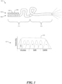
- FIG. 1 depicts a particular, non-limiting embodiment of a high power LED light source 101 in accordance with the teachings herein, and which may be utilized in medical diagnostic equipment such as STS.
- the LED light source 101 in this particular embodiment includes an LED fixture 105 comprising a plurality of blue/UV LEDs 107 and an optical fiber 109.
- the optical fiber 109 includes a first segment 111 in which a mixture of chromophores b, c, d, e and f have been have been mixed or compounded into the polymeric resin used to fabricate the first segment 111, and a second segment 113 which is devoid of any chromophores.
- the emissions spectra 151 of the LED light source 101 is also depicted, and includes emissions peaks corresponding to chromophores b, c, d, e and f, as well as the material a of the second segment 113 of the optical fiber 109.
- the peak corresponding to the LEDs 107 from the light fixture (denoted "LED") is also indicated, as is the cumulative emissions spectrum 153.
- the LED light source 101 excites various fiber segments containing QDs emitting at progressively longer wavelengths to cover the visible to NIR.
- the LED light source 101 may be optically coupled to the end of the optical fiber as depicted in FIG. 3 , or along the length of the fiber.
- the resulting spectrum may be both intense and continuous over the range of interest to the medical diagnostic market.
- Embodiments of the LED light source 101 depicted may be produced which are bright and compact, and provide broad-band illumination.
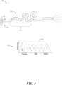
- FIG. 2 depicts another particular, non-limiting embodiment of a high power LED light source 201 in accordance with the teachings herein, and which may also be utilized in medical diagnostic equipment such as STS.
- the LED light source 201 in this particular embodiment includes an LED fixture 205 comprising a plurality of blue/UV LEDs 207 and an optical fiber 209.
- the optical fiber 209 includes a first segment 211 having subsegments a, b, c, d, e and f in which chromophores a, b, c, d, e and f have respectively been mixed or compounded into the polymeric resin used to fabricate the first segment 211.
- the optical fiber 209 further includes a second segment 213 which is devoid of any chromophores.
- the LED light source 201 may be configured to provide the same or similar advantages as those provided by the LED light source 101 of FIG. 1 , and may have the same or similar emissions spectra 251.
- FIG. 3 depicts another particular, non-limiting embodiment of a high power LED light source 301 in accordance with the teachings herein, and which may also be utilized in medical diagnostic equipment such as STS.
- the LED light source 301 in this particular embodiment includes a blue/UV LED fixture 305 and an optical fiber 309.
- the LED fixture 305 in this embodiment is directly coupled to the optical fiber 309.
- the optical fiber 309 includes a first segment 311 having subsegments b, c, d, e and f in which chromophores b, c, d, e and f have respectively been mixed or compounded into the polymeric resin used to fabricate the first segment 311.
- the optical fiber 309 further includes a second segment 313 which is devoid of any chromophores.
- the LED light source 301 may be configured to provide the same or similar advantages as those provided by the LED light source 201 of FIG. 2 , and may have the same or similar emissions spectra 351.
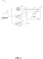
- FIG. 4 depicts a particular, non-limiting embodiment of an STS optical setup 401 which may be utilized in the systems and methodologies described herein.
- This optical set-up is based on the set-up described in Nachabé, R.; Hendriks, B.H.W.; van der Voort, M.; Desjardins, A.E.; Sterenborg, H.J.C.M. Estimation of Biological Chromophores using Diffuse Optical Spectroscopy: Benefit of Extending the UV-VIS Wavelength Range to Include 1000 to 1600 nm. Opt. Expr. 2010, 18, 1432-1442 , which is incorporated herein by reference in its entirety.
- the STS optical setup 401 includes a light source 405 (preferably a halogen lamp), a visible spectrometer 407 and an infrared spectrometer 409, all of which are under control of a computer 403.
- the STS optical setup 401 further includes an optical probe 411.
- the optical probe 411 (and specifically, the tip thereof) is equipped with an illumination fiber 415 which is in optical communication with the light source 405, a VIS detection fiber 419 which is in optical communication with visible spectrometer 407, and an IR detection fiber 417 which is in optical communication with infrared spectrometer 409.
- FIGs. 5-6 depict a particular, non-limiting embodiment of an assembly 601 featuring an integrated liquid-core-optical-fiber (LCOF) and stimulated Raman generation, and a process for making the same.
- LCOF liquid-core-optical-fiber
- This process and assembly are based on those described in Kieu, K.; Schneebeli, L.; Norwood, R.A.; Peyghambarian, N. Integrated Liquid-Core Optical Fibers for Ultra-Efficient Nonlinear Liquid Photonics. Opt. Expr. 2012, 20, 8148-8154 , which is incorporated herein by reference in its entirety.
- FIG. 5a An image of a gap-splice between a single mode fiber (Corning SMF28) and a 10 ⁇ m a liquid core optical fiber (LCOF) is depicted in FIG. 5a .
- FIG. 5b A photo of a gap-splice between two segments of single mode fiber (Corning SMF28 fiber) is depicted in FIG. 5b .
- FIG. 6c depicts the fabrication of an optical subassembly 611 having a liquid access port for incorporation into the assembly 601.
- the optical subassembly 611 comprises an LCOF 608 (here with a 10 ⁇ m core) and a standard single mode fiber 609 (here, Corning SMF28) which are joined across a gap splice 605.
- LCOF 608 and the standard single mode fiber 609 are mounted on a microscope slide 603 with a portion of adhesive tape 607.
- Liquid access is provided by way of a liquid medium disposed in container 613.
- Various liquid media may be utilized for this purpose, although the use of CS 2 is preferred.
- FIG. 6e depicts the assembly of an integrated LCOF 608 filled with CS 2 , which is produced by a similar process.
- a photograph of an integrated 1m long LCOF filled with CS 2 is shown in FIG. 5d .
- the assembly 601 produced by the foregoing methods includes a laser 617, a dichroic (or IR) filter 619, a polarizing beam splitter (PBS) 621, a photodiode (PD) 625, a gold-coated mirror 623, a microscope objective (MO) 627, and an optical spectrum analyzer (OSA) 629.
- the assembly 601 further includes portions of the LCOF 608 and the standard single mode fiber 609 noted above.
- FIG. 7 depicts the results which may be achieved by mixing QDs in different concentrations.
- the results depicted are for three different mixtures of QDs produced in this manner.
- this approach may be utilized to produce a tunable broadband spectrum.
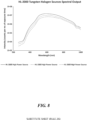
- FIG. 8 depicts a spectrum (obtained from the manufacturer) of Ocean Optics HL-2000-HP-FHSA tungsten halogen light sources. As seen therein, these light sources produce varying output spectra, depending on whether the light source is configured as a high power source, a standard source or a long-life source.
- FIG. 9 is a typical absorption 901 and photoluminescence 903 spectra for CuInZnSeS quantum dots, which are a preferred fluorophore in the devices and methodologies disclosed herein.
- These QDs are substantially free of toxic elements, and are believed to be non-carcinogenic. Moreover, these QDs may have an emission quantum yield in excess of 70%, or greater than 90%, and have an absorption spectrum with a maximum intensity at wavelengths less than 400 nm.
- CuInZnSeS quantum dots can be made to have minimal overlap 902 between their absorption 901 and photoluminescence 903 peaks. As a result, very little of the radiation emitted by these quantum dots as a result of fluorescence undergoes subsequent reabsorption. Moreover, CuInZnSeS quantum dots can be fabricated with absorption peaks outside of the visible region (typically within the UV region), and emission spectra within it. Consequently, the photoluminescence process that these quantum dots undergo has the effect of converting a portion of the incident UV or blue radiation into visible-NIR wavelengths, thus making them ideal for medical applications.
- FIG. 10 is a graph of the photoluminescence spectra arising from different sizes and compositions of quantum dots composed of CuInS 2 , CuInSe 2 , ZnS, ZnSe, and combinations thereof. As seen therein, these materials provide accessible peak emissions within the range of 400 nm -1200 nm.
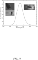
- FIG. 11 is a graph of the photoluminescence spectra arising from a prototype fiber-coupled light source. Only one size of QDs is used in the prototype used to generate these spectra.
- the optical fiber attached to the prototype is connected to a Thorlabs SMA fiber adapter.
- the output of the device is measured suing fiber-coupled spectrometer at a short (1.5 ms) integration time.
- Photos of the device excited by a blue LED revealed a bright red dot at the end of the Thorlabs fiber adapter, thus confirming coupling.
- Photos of the device excited by a small ChanZon LED showed bright red light coming out of the fiber adapter after coupling from QDs to the fiber.
- FIG. 12 is a graph showing broadband PL of 590-nm QDs after propagation through a sample comprising bovine hemoglobin in a biological buffer. As seen therein, the broadband PL of 590-nm QDs is significantly altered upon propagation through the sample. Depth and concentration information can be extracted by analysis of these spectra.
- FIG. 10 is a graph of the photoluminescence arising from different sizes and compositions of CuInZnSeS quantum dots that show many different emission wavelengths of these quantum dots that span the spectral range from 400-1200 nm.
- the shape of the spectrum may be readily modified and tailored to the ideal spectrum.
- the shape of the spectrum including the number of peaks, number of troughs, slope of the spectrum, and other signatures, may be tailored based on the size and composition of the quantum dots chosen.
- the QDs mixtures have an emission quantum yield of greater than 50%. It will be appreciated that this approach may be utilized to achieve a spectral output that is most conducive to the specific application.
- luminescent materials may be utilized in the devices, structures and methodologies disclosed herein.
- one class of such materials are the colloidal semiconductor nanocrystals commonly known as quantum dots (QDs). These materials are advantageous in that they provide various size-tunable optical properties (including size tunable photoluminescence), and may be inexpensively processed from liquids. QDs are very effective at absorbing a broad spectrum of light and then converting that energy into emitted light of a single color that is determined by their size.
- Optical properties (such as, for example, absorption and emission spectra, PL lifetimes and Stokes shift) may be programmed into these materials by tailoring the manufacturing conditions to realize different sizes, shapes, compositions, and/or heterostructuring.
- the output of the device was measured using a fiber-coupled spectrometer at a short (1.5 ms) integration time. Bright emission out of the fiber was easily observed by eye, both when the LSC was excited by a regular blue flashlight (left) as well as when using the blue LED (right).
- This simple prototype illustrates a unique, tunable light source.
- a miniature (yet highly flexible) broadband light source may be produced.
- the output spectrum may be easily modified to compensate for the drop of the sensitivity of Si detectors around 1000-1100 nm.
- PL of a single-sized QDs with ⁇ 590-nm peak was used to confirm that even PL spectrum of a single distinct type of CuInSe x S 2-x /ZnS QDs is broad enough to see signatures of some of the biological species.
- distinct absorption peaks of bovine hemoglobin were found to affect spectral shape and intensity of the QDs PL as it propagates through the sample (liquid solution of the bovine hemoglobin in biologically-relevant buffer, PBS).
- the arrow in Fig. 12 depicts increasing concentration of the bovine hemoglobin, which is a good proxy for increasing thickness of tissues.
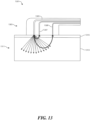
- FIG. 13 is an illustration of a particular, non-limiting embodiment of an optical spectroscopic imaging device in accordance with the teachings herein.
- DOSI Diffuse Optical Spectroscopic Imaging
- NIR near-infrared
- the remission is then analyzed via a set of mathematical photon transport models based on the Beer-Lambert Law modified to predict multiple photon scattering and diffusion in living tissues. From this, various useful information may be derived such as, for example, tissue oximetry that may be utilized to diagnose conditions such as melanoma.
- a typical DOSI instrument consists of a probe 1101 equipped with a tunable NIR laser light source 1103 and various photon detectors 1105, 1106 placed at differing distances away from the light source 1103.
- the light source 1103 may be of the type disclosed herein.
- This "banana" shaped light diffusion path is the reason why detectors closest to the source are able to analyze superficial portions of the tissue (such as subcutaneous tissue 1109 ), while the furthest detectors are capable of a deeper interrogation (such as skeletal muscle 1111). There is a limit to how far away the detectors can be.
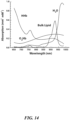
- DOSI operates on the principal that every chromophore in the target tissue absorbs the most light at their own unique and specific wavelength. This can be seen in FIG. 14 , which is an example of absorption spectra of various chromophores at different wavelengths (including NIR) which may be obtained with the device depicted in FIG. 13 .
- NIR absorption spectra of various chromophores at different wavelengths
- water absorption of NIR light is highest around the 980nm range.
- oxygenated and de-oxygenated hemoglobin have dramatically different absorption profiles, and are thus relatively easy to differentiate from one another.
- chromophore content and composition can be individually separated and analyzed to determine, for example, differences between benign lesions and malignant melanoma.
- the photoluminescence of the luminescent material may have a maximum intensity at wavelengths in the range of 400 nm to 2000 nm, more preferably in the range of 550 nm to 1700 nm, and most preferably in the range of 550 nm to 750 nm.
- the fluorophores may emit a spectrum of light having full-width at maximum intensity that is greater than 1 nm, greater than 20 nm, greater than 30 nm, greater than 40 nm, greater than 100nm, or greater than 200nm.
- the photoluminescence of the luminescent material may have a maximum intensity at wavelengths greater than 550 nm.
- the photoluminescence of the luminescent material may be characterized by a quantum yield of at least 30%, at least 50%, at least 70%, or at least 80%.
- a spectrum selecting optical element may be placed in the optical path between the irradiated article and the incident sunlight.
- Such an optical element may include, for example, one or more elements selected from the group consisting of light filters, quantum dot films and colored glasses.
- a spectrum selecting optical element of this type may allow only a given portion of the spectrum to pass.
- QDs and fluorophores of various composition may be utilized in the systems and methodologies disclosed herein. Some of these compositions have been noted above.
- QDs and fluorophores having compositions selected from the group consisting of CuInS 2 , CuInSe 2 , AgInS 2 , AgInSe 2 , ZnS, ZnSe, CuInZnSeS, CuGaS 2 , and alloys of the foregoing may be utilized.
- the use of QDs and fluorophores having the composition CuInSe x S 2-x /ZnS are preferred.
- two or more distinct types of quantum dots may be utilized in the systems, methodologies and compositions described herein. These quantum dots may be compositionally distinct.
- the luminescent materials utilized herein may comprise a first type of quantum dot based on a first chemistry, and a second type of quantum dot based on a second chemistry which is distinct from the first chemistry.
- the first type of quantum dot may comprise, for example, CuInS 2
- the second type of quantum dot may comprise AgInSe 2 .
- the luminescent materials described herein may comprise a first type of quantum dot based on a first set of dimensions (or distribution of dimensions) of the quantum dots, and a second type of quantum dot based on a second set of dimensions (or distribution of dimensions) of the quantum dots which is distinct from the first set of dimensions (or distribution of dimensions) of the quantum dots.
- the first type of quantum dot may comprise generally spherical quantum dots having a first diameter (e.g., 10 nm)
- the second type of quantum dot may comprise generally spherical quantum dots having a second diameter (e.g., 30 nm).
Landscapes
- Physics & Mathematics (AREA)
- Spectroscopy & Molecular Physics (AREA)
- Health & Medical Sciences (AREA)
- Life Sciences & Earth Sciences (AREA)
- General Physics & Mathematics (AREA)
- Optics & Photonics (AREA)
- Heart & Thoracic Surgery (AREA)
- Surgery (AREA)
- Engineering & Computer Science (AREA)
- Biomedical Technology (AREA)
- Biophysics (AREA)
- Medical Informatics (AREA)
- Molecular Biology (AREA)
- Pathology (AREA)
- Animal Behavior & Ethology (AREA)
- General Health & Medical Sciences (AREA)
- Public Health (AREA)
- Veterinary Medicine (AREA)
- Investigating, Analyzing Materials By Fluorescence Or Luminescence (AREA)
- Investigating Or Analysing Materials By Optical Means (AREA)
Claims (15)
- Optisches Element, umfassend:eine optische Faser; undeine Vielzahl von Fluorophoren in optischer Kommunikation mit der optischen Faser;wobei die Fluorophore eine Quantenausbeute von mehr als 50 % aufweisen, wobei die Fluorophore ein Lichtspektrum emittieren, das eine maximale Intensität bei Wellenlängen innerhalb des Bereichs von 400 nm bis 2000 nm aufweist;wobei die Vielzahl von Fluorophoren Quantenpunkte sind.
- Optisches Element nach Anspruch 1, wobei das optische Element eine durchschnittliche Transparenz von mehr als 50 % bei Wellenlängen innerhalb des Bereichs von 550 nm bis 1700 nm aufweist.
- Optisches Element nach Anspruch 1, wobei die Quantenpunkte ein Material umfassen, das aus der Gruppe, bestehend aus CuInS2, CuInSe2, AgInS2, AgInSe2, ZnS, ZnSe und Legierungen der vorstehenden ausgewählt ist.
- Optisches Element nach Anspruch 1, wobei die optische Faser einen Kern und einen Mantel aufweist, wobei die optische Faser an einem Element befestigt ist, das ein Medium enthält, in dem die Fluorophore angeordnet sind.
- Optisches Element nach Anspruch 1, ferner umfassend:
mindestens ein blaues oder UV-LED-optisches Element, das an dem Ende der optischen Faser angeordnet ist und mit dieser in optischer Kommunikation steht. - Optisches Element nach Anspruch 1, ferner umfassend:
mindestens ein blaues oder UV-LED-optisches Element, das entlang eines Abschnitts der optischen Faser angeordnet ist und mit dieser in optischer Kommunikation steht. - Optisches Element nach Anspruch 1, wobei Fluorophore das von der Lichtquelle einfallende Licht um weniger als 5 % streuen.
- Optisches Element nach Anspruch 1, wobei die Vielzahl von Fluorophoren eine erste Vielzahl von einem ersten Fluorophor und eine zweite Vielzahl von einem zweiten Fluorophor beinhaltet, wobei das erste und das zweite Fluorophor verschieden sind und wobei die erste und die zweite Vielzahl von Fluorophoren innerhalb des an der optischen Faser befestigten Mediums homogen gemischt sind.
- Optisches Element nach Anspruch 1 in Kombination mit einer Lichtquelle, wobei die Vielzahl von Fluorophoren einen Satz von Fluorophoren F = F1, ..., Fn beinhaltet, wobein ≥ 2, wobei jeder Fluorophor Fi , wobei i ∈ [1, ..., n], ein Emissionsspektrum aufweist, das durch eine maximale Intensität bei der Wellenlänge λi gekennzeichnet ist, wobei λi > ... > λn , und wobei die Vielzahl von Fluorophoren innerhalb der optischen Faser angeordnet ist, um einen Gradienten zu bilden.
- Optisches Element nach Anspruch 1 in Kombination mit einer Lichtquelle, wobei die Vielzahl von Fluorophoren einen Satz von Fluorophoren F = F1, ..., Fn beinhaltet, wobein ≥ 2, wobei jeder Fluorophor Fi , wobei i ∈ [1, ..., n], ein Emissionsspektrum aufweist, das durch eine maximale Intensität bei der Wellenlänge λi gekennzeichnet ist, wobei λi > ... > λn , und wobei die Vielzahl von Fluorophoren innerhalb von Medien angeordnet ist, die an den optischen Fasern befestigt sind, und die optischen Fasern mit der gemeinsamen optischen Ausgangsfaser verbunden sind.
- Optisches Element nach Anspruch 1, wobei ein Ausgangsspektrum so manipuliert wird, dass das Signal-Rausch-Verhältnis über den gesamten spektralen Bereich optimiert wird, indem die Beleuchtungsintensität mit den Empfindlichkeitsprofilen der Systeme zum Erkennen übereinstimmt.
- Optisches Element nach Anspruch 1, wobei ein Ausgangsspektrum so manipuliert wird, dass das Signal-Rausch-Verhältnis über den gesamten spektralen Bereich optimiert wird, indem das Absorptionsprofil des Gewebes übereinstimmt.
- Optisches Element nach Anspruch 1, wobei die Faseroptik in eine Vielzahl von austauschbaren Segmenten segmentiert ist.
- Optisches Element nach Anspruch 1, wobei die Vielzahl von Fluorophoren benachbart zu der optischen Faser angeordnet ist.
- Optisches Element nach Anspruch 1, wobei die Fluorophore ein Lichtspektrum emittieren, das eine volle Breite bei maximaler Intensität von mehr als 40 nm aufweist.
Applications Claiming Priority (2)
| Application Number | Priority Date | Filing Date | Title |
|---|---|---|---|
| US201762519857P | 2017-06-14 | 2017-06-14 | |
| PCT/US2018/037654 WO2018232192A1 (en) | 2017-06-14 | 2018-06-14 | Fiber-coupled broadband light source |
Publications (3)
| Publication Number | Publication Date |
|---|---|
| EP3639014A1 EP3639014A1 (de) | 2020-04-22 |
| EP3639014A4 EP3639014A4 (de) | 2020-12-30 |
| EP3639014B1 true EP3639014B1 (de) | 2024-12-11 |
Family
ID=64656462
Family Applications (1)
| Application Number | Title | Priority Date | Filing Date |
|---|---|---|---|
| EP18817970.9A Active EP3639014B1 (de) | 2017-06-14 | 2018-06-14 | Fasergekoppelte breitbandlichtquelle |
Country Status (6)
| Country | Link |
|---|---|
| US (2) | US20180364098A1 (de) |
| EP (1) | EP3639014B1 (de) |
| KR (1) | KR102843277B1 (de) |
| CN (1) | CN110869750A (de) |
| CA (1) | CA3067353A1 (de) |
| WO (1) | WO2018232192A1 (de) |
Families Citing this family (17)
| Publication number | Priority date | Publication date | Assignee | Title |
|---|---|---|---|---|
| USRE46672E1 (en) | 2006-07-13 | 2018-01-16 | Velodyne Lidar, Inc. | High definition LiDAR system |
| US10627490B2 (en) | 2016-01-31 | 2020-04-21 | Velodyne Lidar, Inc. | Multiple pulse, LIDAR based 3-D imaging |
| US10018726B2 (en) | 2016-03-19 | 2018-07-10 | Velodyne Lidar, Inc. | Integrated illumination and detection for LIDAR based 3-D imaging |
| WO2017210418A1 (en) | 2016-06-01 | 2017-12-07 | Velodyne Lidar, Inc. | Multiple pixel scanning lidar |
| CN110914705B (zh) | 2017-03-31 | 2024-04-26 | 威力登激光雷达美国有限公司 | 用于集成lidar照明功率控制的设备、系统和方法 |
| CN110809704B (zh) | 2017-05-08 | 2022-11-01 | 威力登激光雷达美国有限公司 | Lidar数据获取与控制 |
| US11294041B2 (en) * | 2017-12-08 | 2022-04-05 | Velodyne Lidar Usa, Inc. | Systems and methods for improving detection of a return signal in a light ranging and detection system |
| US11971507B2 (en) | 2018-08-24 | 2024-04-30 | Velodyne Lidar Usa, Inc. | Systems and methods for mitigating optical crosstalk in a light ranging and detection system |
| US10712434B2 (en) | 2018-09-18 | 2020-07-14 | Velodyne Lidar, Inc. | Multi-channel LIDAR illumination driver |
| US11082010B2 (en) | 2018-11-06 | 2021-08-03 | Velodyne Lidar Usa, Inc. | Systems and methods for TIA base current detection and compensation |
| US11885958B2 (en) | 2019-01-07 | 2024-01-30 | Velodyne Lidar Usa, Inc. | Systems and methods for a dual axis resonant scanning mirror |
| US12061263B2 (en) | 2019-01-07 | 2024-08-13 | Velodyne Lidar Usa, Inc. | Systems and methods for a configurable sensor system |
| US10613203B1 (en) | 2019-07-01 | 2020-04-07 | Velodyne Lidar, Inc. | Interference mitigation for light detection and ranging |
| CN113125345B (zh) * | 2021-03-05 | 2022-12-23 | 上海大学 | 一种铜离子检测的光纤传感器及其制备方法 |
| FR3154165B1 (fr) * | 2023-10-13 | 2025-11-14 | Aoi Tech | Système d’éclairage à large spectre |
| KR102886582B1 (ko) * | 2024-01-11 | 2025-11-13 | 울산과학기술원 | 양자 광원 장치 |
| CN117590521B (zh) * | 2024-01-18 | 2024-03-19 | 北京镭科光电科技有限公司 | 利用液芯光导管的半导体激光耦合传输成像装置及设备 |
Family Cites Families (24)
| Publication number | Priority date | Publication date | Assignee | Title |
|---|---|---|---|---|
| JP3365021B2 (ja) * | 1993-12-27 | 2003-01-08 | 株式会社ブリヂストン | 光伝送体 |
| US6103535A (en) * | 1996-05-31 | 2000-08-15 | University Of Maryland | Optical fiber evanescent field excited fluorosensor and method of manufacture |
| US6514277B1 (en) * | 1999-06-11 | 2003-02-04 | Photonics Research Ontario | Fiber optic multitasking probe |
| US6337945B1 (en) * | 1999-09-15 | 2002-01-08 | Supervision International, Inc. | Fiber optic light bar |
| US20020186921A1 (en) * | 2001-06-06 | 2002-12-12 | Schumacher Lynn C. | Multiwavelength optical fiber devices |
| US7208007B2 (en) * | 2003-08-07 | 2007-04-24 | Cutera, Inc. | System and method utilizing guided fluorescence for high intensity applications |
| US20060024833A1 (en) * | 2004-07-27 | 2006-02-02 | Molecular Probes, Inc. | Fluorescent metal ion indicators with large stokes shift |
| JP2006261077A (ja) * | 2005-03-15 | 2006-09-28 | Hitoshi Yagisawa | 光ファイバーライト |
| CA2597697C (en) * | 2005-06-23 | 2014-12-02 | Rensselaer Polytechnic Institute | Package design for producing white light with short-wavelength leds and down-conversion materials |
| US8247551B2 (en) * | 2007-01-26 | 2012-08-21 | Duquesne University Of The Holy Spirit | Lead sensor and methods of use |
| US7768640B2 (en) * | 2007-05-07 | 2010-08-03 | The Board Of Trustees Of The University Of Illinois | Fluorescence detection enhancement using photonic crystal extraction |
| ES2399814T3 (es) * | 2009-01-21 | 2013-04-03 | Alcon Research, Ltd. | Endoiluminación oftálmica que utiliza luz generada por fibra |
| WO2011050441A1 (en) * | 2009-10-30 | 2011-05-05 | Institut National D'optique | Fluorescence-based light emitting device |
| WO2011088571A1 (en) * | 2010-01-25 | 2011-07-28 | University Health Network | Device, system and method for quantifying fluorescence and optical properties |
| WO2012142138A2 (en) * | 2011-04-11 | 2012-10-18 | The Johns Hopkins University | Cuinse/zns nir-quantum dots (qds) for biomedical imaging |
| EP2756303B1 (de) * | 2011-09-15 | 2018-08-22 | The Trustees of Columbia University in the City of New York | Messung eines fluoreszierenden analyten mittels gewebeerregung |
| CN105163650B (zh) * | 2013-05-03 | 2018-12-07 | 飞利浦照明控股有限公司 | 具有经适配的光谱输出的光源 |
| WO2015057165A1 (en) * | 2013-10-14 | 2015-04-23 | Agency For Science, Technology And Research | Non-motorized optical multiplexing for the simultaneous detection of dna target amplicons in a polymerase chain reaction solution |
| GB201418725D0 (en) * | 2014-10-21 | 2014-12-03 | Imp Innovations Ltd | A light source |
| US10170022B2 (en) | 2015-06-10 | 2019-01-01 | UbiQD, Inc. | Photoluminescent retroreflector |
| US9382432B1 (en) | 2015-09-21 | 2016-07-05 | Ubiqd, Llc | Quantum dot security inks |
| US9964488B2 (en) | 2015-09-21 | 2018-05-08 | UbiQD, Inc. | Methods of authenticating security inks |
| US10082387B2 (en) | 2016-03-09 | 2018-09-25 | UbiQD, Inc. | Fluorescent liquid penetrants and methods of nondestructive testing |
| CN110915001B (zh) | 2017-05-09 | 2023-05-02 | 优比库德股份有限公司 | 用于农业应用的发光光学元件 |
-
2018
- 2018-06-14 CN CN201880046052.9A patent/CN110869750A/zh active Pending
- 2018-06-14 EP EP18817970.9A patent/EP3639014B1/de active Active
- 2018-06-14 KR KR1020207000773A patent/KR102843277B1/ko active Active
- 2018-06-14 US US16/009,158 patent/US20180364098A1/en not_active Abandoned
- 2018-06-14 WO PCT/US2018/037654 patent/WO2018232192A1/en not_active Ceased
- 2018-06-14 CA CA3067353A patent/CA3067353A1/en active Pending
-
2022
- 2022-05-17 US US17/746,911 patent/US12085443B2/en active Active
Also Published As
| Publication number | Publication date |
|---|---|
| WO2018232192A1 (en) | 2018-12-20 |
| US20220276091A1 (en) | 2022-09-01 |
| KR102843277B1 (ko) | 2025-08-06 |
| EP3639014A1 (de) | 2020-04-22 |
| CA3067353A1 (en) | 2018-12-20 |
| US20180364098A1 (en) | 2018-12-20 |
| CN110869750A (zh) | 2020-03-06 |
| EP3639014A4 (de) | 2020-12-30 |
| KR20200015744A (ko) | 2020-02-12 |
| US12085443B2 (en) | 2024-09-10 |
Similar Documents
| Publication | Publication Date | Title |
|---|---|---|
| US12085443B2 (en) | Fiber-coupled broadband light source | |
| Makarov et al. | Fiber-coupled luminescent concentrators for medical diagnostics, agriculture, and telecommunications | |
| Hayashi et al. | A broadband LED source in visible to short-wave-infrared wavelengths for spectral tumor diagnostics | |
| CN101819149B (zh) | 高性能荧光光学传感器 | |
| Liu et al. | Measurement and numerical studies of optical properties of YAG: Ce phosphor for white light-emitting diode packaging | |
| US10182702B2 (en) | Light-emitting apparatus including photoluminescent layer | |
| TWI493242B (zh) | 色溫調控裝置及使用其之照明設備,以及色溫調控之方法 | |
| USRE49093E1 (en) | Light-emitting apparatus including photoluminescent layer | |
| EP3201583B1 (de) | Röhrenlose breitbandige nahinfrarotlichtquelle | |
| JP2007171186A (ja) | 試料検出システム | |
| KR20130114049A (ko) | 표면 조명 장치 | |
| US8981402B2 (en) | White LED lighting device, and optical lens | |
| US20090153837A1 (en) | Optical power monitor based on thermo-chromic material | |
| RU2690174C2 (ru) | Управление цветом люминесцентного световода | |
| Yalçın et al. | Colored radiative cooling coatings with fluorescence | |
| Liu et al. | Contrast-enhanced fluorescence microscope by LED integrated excitation cubes | |
| US20240304764A1 (en) | Light-emitting device and electronic apparatus using same | |
| Seddon | Biomedical applications in probing deep tissue using mid-infrared supercontinuum optical biopsy | |
| Yalçın et al. | Monte Carlo method solution of the broadband fluorescent radiative transfer equation considering fluorescent cascade | |
| CN109030419A (zh) | 一种宽幅变温固态发光绝对量子产率测量方法 | |
| Alyami et al. | Synergistic fluorescence with significant red shift in coumarin-doped PMMA matrices using CdTe quantum dots for luminescent concentrator 2D position sensing | |
| Schwarz et al. | Prospective evaluation of a portable depth-sensitive optical spectroscopy device to identify oral neoplasia | |
| Ryckaert et al. | Determination of the optimal amount of scattering in a wavelength conversion plate for white LEDs | |
| Lazarjan et al. | Miniaturized wireless cell spectrophotometer platform in visible and near-IR range | |
| Thi et al. | The application of dual-layer remote phosphor geometry in achieving higher color quality of WLEDs |
Legal Events
| Date | Code | Title | Description |
|---|---|---|---|
| STAA | Information on the status of an ep patent application or granted ep patent |
Free format text: STATUS: THE INTERNATIONAL PUBLICATION HAS BEEN MADE |
|
| PUAI | Public reference made under article 153(3) epc to a published international application that has entered the european phase |
Free format text: ORIGINAL CODE: 0009012 |
|
| STAA | Information on the status of an ep patent application or granted ep patent |
Free format text: STATUS: REQUEST FOR EXAMINATION WAS MADE |
|
| 17P | Request for examination filed |
Effective date: 20191216 |
|
| AK | Designated contracting states |
Kind code of ref document: A1 Designated state(s): AL AT BE BG CH CY CZ DE DK EE ES FI FR GB GR HR HU IE IS IT LI LT LU LV MC MK MT NL NO PL PT RO RS SE SI SK SM TR |
|
| AX | Request for extension of the european patent |
Extension state: BA ME |
|
| DAV | Request for validation of the european patent (deleted) | ||
| DAX | Request for extension of the european patent (deleted) | ||
| RIN1 | Information on inventor provided before grant (corrected) |
Inventor name: MAKAROV, NIKOLAY Inventor name: MCDANIEL, HUNTER Inventor name: BERGREN, MATTHEW |
|
| A4 | Supplementary search report drawn up and despatched |
Effective date: 20201201 |
|
| RIC1 | Information provided on ipc code assigned before grant |
Ipc: G01J 3/10 20060101ALI20201125BHEP Ipc: G01N 21/75 20060101ALI20201125BHEP Ipc: F21V 8/00 20060101ALI20201125BHEP Ipc: A61B 5/00 20060101ALI20201125BHEP Ipc: G02B 6/42 20060101ALI20201125BHEP Ipc: G01N 21/62 20060101ALI20201125BHEP Ipc: G01N 21/64 20060101ALI20201125BHEP Ipc: G01N 21/00 20060101ALI20201125BHEP Ipc: G01N 21/77 20060101AFI20201125BHEP |
|
| GRAP | Despatch of communication of intention to grant a patent |
Free format text: ORIGINAL CODE: EPIDOSNIGR1 |
|
| STAA | Information on the status of an ep patent application or granted ep patent |
Free format text: STATUS: GRANT OF PATENT IS INTENDED |
|
| INTG | Intention to grant announced |
Effective date: 20240724 |
|
| GRAS | Grant fee paid |
Free format text: ORIGINAL CODE: EPIDOSNIGR3 |
|
| GRAA | (expected) grant |
Free format text: ORIGINAL CODE: 0009210 |
|
| STAA | Information on the status of an ep patent application or granted ep patent |
Free format text: STATUS: THE PATENT HAS BEEN GRANTED |
|
| AK | Designated contracting states |
Kind code of ref document: B1 Designated state(s): AL AT BE BG CH CY CZ DE DK EE ES FI FR GB GR HR HU IE IS IT LI LT LU LV MC MK MT NL NO PL PT RO RS SE SI SK SM TR |
|
| REG | Reference to a national code |
Ref country code: GB Ref legal event code: FG4D |
|
| REG | Reference to a national code |
Ref country code: CH Ref legal event code: EP |
|
| REG | Reference to a national code |
Ref country code: IE Ref legal event code: FG4D |
|
| REG | Reference to a national code |
Ref country code: DE Ref legal event code: R096 Ref document number: 602018077555 Country of ref document: DE |
|
| REG | Reference to a national code |
Ref country code: NL Ref legal event code: FP |
|
| REG | Reference to a national code |
Ref country code: LT Ref legal event code: MG9D |
|
| PG25 | Lapsed in a contracting state [announced via postgrant information from national office to epo] |
Ref country code: HR Free format text: LAPSE BECAUSE OF FAILURE TO SUBMIT A TRANSLATION OF THE DESCRIPTION OR TO PAY THE FEE WITHIN THE PRESCRIBED TIME-LIMIT Effective date: 20241211 |
|
| PG25 | Lapsed in a contracting state [announced via postgrant information from national office to epo] |
Ref country code: FI Free format text: LAPSE BECAUSE OF FAILURE TO SUBMIT A TRANSLATION OF THE DESCRIPTION OR TO PAY THE FEE WITHIN THE PRESCRIBED TIME-LIMIT Effective date: 20241211 |
|
| PG25 | Lapsed in a contracting state [announced via postgrant information from national office to epo] |
Ref country code: BG Free format text: LAPSE BECAUSE OF FAILURE TO SUBMIT A TRANSLATION OF THE DESCRIPTION OR TO PAY THE FEE WITHIN THE PRESCRIBED TIME-LIMIT Effective date: 20241211 |
|
| PG25 | Lapsed in a contracting state [announced via postgrant information from national office to epo] |
Ref country code: ES Free format text: LAPSE BECAUSE OF FAILURE TO SUBMIT A TRANSLATION OF THE DESCRIPTION OR TO PAY THE FEE WITHIN THE PRESCRIBED TIME-LIMIT Effective date: 20241211 |
|
| PG25 | Lapsed in a contracting state [announced via postgrant information from national office to epo] |
Ref country code: NO Free format text: LAPSE BECAUSE OF FAILURE TO SUBMIT A TRANSLATION OF THE DESCRIPTION OR TO PAY THE FEE WITHIN THE PRESCRIBED TIME-LIMIT Effective date: 20250311 |
|
| PG25 | Lapsed in a contracting state [announced via postgrant information from national office to epo] |
Ref country code: LV Free format text: LAPSE BECAUSE OF FAILURE TO SUBMIT A TRANSLATION OF THE DESCRIPTION OR TO PAY THE FEE WITHIN THE PRESCRIBED TIME-LIMIT Effective date: 20241211 Ref country code: GR Free format text: LAPSE BECAUSE OF FAILURE TO SUBMIT A TRANSLATION OF THE DESCRIPTION OR TO PAY THE FEE WITHIN THE PRESCRIBED TIME-LIMIT Effective date: 20250312 |
|
| PG25 | Lapsed in a contracting state [announced via postgrant information from national office to epo] |
Ref country code: RS Free format text: LAPSE BECAUSE OF FAILURE TO SUBMIT A TRANSLATION OF THE DESCRIPTION OR TO PAY THE FEE WITHIN THE PRESCRIBED TIME-LIMIT Effective date: 20250311 |
|
| REG | Reference to a national code |
Ref country code: AT Ref legal event code: MK05 Ref document number: 1750744 Country of ref document: AT Kind code of ref document: T Effective date: 20241211 |
|
| PG25 | Lapsed in a contracting state [announced via postgrant information from national office to epo] |
Ref country code: SM Free format text: LAPSE BECAUSE OF FAILURE TO SUBMIT A TRANSLATION OF THE DESCRIPTION OR TO PAY THE FEE WITHIN THE PRESCRIBED TIME-LIMIT Effective date: 20241211 |
|
| PG25 | Lapsed in a contracting state [announced via postgrant information from national office to epo] |
Ref country code: PL Free format text: LAPSE BECAUSE OF FAILURE TO SUBMIT A TRANSLATION OF THE DESCRIPTION OR TO PAY THE FEE WITHIN THE PRESCRIBED TIME-LIMIT Effective date: 20241211 |
|
| PGFP | Annual fee paid to national office [announced via postgrant information from national office to epo] |
Ref country code: DE Payment date: 20250627 Year of fee payment: 8 |
|
| PG25 | Lapsed in a contracting state [announced via postgrant information from national office to epo] |
Ref country code: IS Free format text: LAPSE BECAUSE OF FAILURE TO SUBMIT A TRANSLATION OF THE DESCRIPTION OR TO PAY THE FEE WITHIN THE PRESCRIBED TIME-LIMIT Effective date: 20250411 |
|
| PGFP | Annual fee paid to national office [announced via postgrant information from national office to epo] |
Ref country code: NL Payment date: 20250626 Year of fee payment: 8 |
|
| PG25 | Lapsed in a contracting state [announced via postgrant information from national office to epo] |
Ref country code: PT Free format text: LAPSE BECAUSE OF FAILURE TO SUBMIT A TRANSLATION OF THE DESCRIPTION OR TO PAY THE FEE WITHIN THE PRESCRIBED TIME-LIMIT Effective date: 20250411 |
|
| PG25 | Lapsed in a contracting state [announced via postgrant information from national office to epo] |
Ref country code: EE Free format text: LAPSE BECAUSE OF FAILURE TO SUBMIT A TRANSLATION OF THE DESCRIPTION OR TO PAY THE FEE WITHIN THE PRESCRIBED TIME-LIMIT Effective date: 20241211 |
|
| PGFP | Annual fee paid to national office [announced via postgrant information from national office to epo] |
Ref country code: FR Payment date: 20250625 Year of fee payment: 8 |
|
| PG25 | Lapsed in a contracting state [announced via postgrant information from national office to epo] |
Ref country code: AT Free format text: LAPSE BECAUSE OF FAILURE TO SUBMIT A TRANSLATION OF THE DESCRIPTION OR TO PAY THE FEE WITHIN THE PRESCRIBED TIME-LIMIT Effective date: 20241211 Ref country code: RO Free format text: LAPSE BECAUSE OF FAILURE TO SUBMIT A TRANSLATION OF THE DESCRIPTION OR TO PAY THE FEE WITHIN THE PRESCRIBED TIME-LIMIT Effective date: 20241211 |
|
| PG25 | Lapsed in a contracting state [announced via postgrant information from national office to epo] |
Ref country code: SK Free format text: LAPSE BECAUSE OF FAILURE TO SUBMIT A TRANSLATION OF THE DESCRIPTION OR TO PAY THE FEE WITHIN THE PRESCRIBED TIME-LIMIT Effective date: 20241211 |
|
| PG25 | Lapsed in a contracting state [announced via postgrant information from national office to epo] |
Ref country code: CZ Free format text: LAPSE BECAUSE OF FAILURE TO SUBMIT A TRANSLATION OF THE DESCRIPTION OR TO PAY THE FEE WITHIN THE PRESCRIBED TIME-LIMIT Effective date: 20241211 |
|
| PG25 | Lapsed in a contracting state [announced via postgrant information from national office to epo] |
Ref country code: IT Free format text: LAPSE BECAUSE OF FAILURE TO SUBMIT A TRANSLATION OF THE DESCRIPTION OR TO PAY THE FEE WITHIN THE PRESCRIBED TIME-LIMIT Effective date: 20241211 |
|
| PG25 | Lapsed in a contracting state [announced via postgrant information from national office to epo] |
Ref country code: SE Free format text: LAPSE BECAUSE OF FAILURE TO SUBMIT A TRANSLATION OF THE DESCRIPTION OR TO PAY THE FEE WITHIN THE PRESCRIBED TIME-LIMIT Effective date: 20241211 |
|
| REG | Reference to a national code |
Ref country code: DE Ref legal event code: R097 Ref document number: 602018077555 Country of ref document: DE |
|
| PG25 | Lapsed in a contracting state [announced via postgrant information from national office to epo] |
Ref country code: DK Free format text: LAPSE BECAUSE OF FAILURE TO SUBMIT A TRANSLATION OF THE DESCRIPTION OR TO PAY THE FEE WITHIN THE PRESCRIBED TIME-LIMIT Effective date: 20241211 |
|
| PLBE | No opposition filed within time limit |
Free format text: ORIGINAL CODE: 0009261 |
|
| STAA | Information on the status of an ep patent application or granted ep patent |
Free format text: STATUS: NO OPPOSITION FILED WITHIN TIME LIMIT |
|
| REG | Reference to a national code |
Ref country code: CH Ref legal event code: L10 Free format text: ST27 STATUS EVENT CODE: U-0-0-L10-L00 (AS PROVIDED BY THE NATIONAL OFFICE) Effective date: 20251022 |
|
| 26N | No opposition filed |
Effective date: 20250912 |
|
| REG | Reference to a national code |
Ref country code: CH Ref legal event code: H13 Free format text: ST27 STATUS EVENT CODE: U-0-0-H10-H13 (AS PROVIDED BY THE NATIONAL OFFICE) Effective date: 20260127 |
|
| PG25 | Lapsed in a contracting state [announced via postgrant information from national office to epo] |
Ref country code: MC Free format text: LAPSE BECAUSE OF FAILURE TO SUBMIT A TRANSLATION OF THE DESCRIPTION OR TO PAY THE FEE WITHIN THE PRESCRIBED TIME-LIMIT Effective date: 20241211 |
|
| PG25 | Lapsed in a contracting state [announced via postgrant information from national office to epo] |
Ref country code: LU Free format text: LAPSE BECAUSE OF NON-PAYMENT OF DUE FEES Effective date: 20250614 |
|
| GBPC | Gb: european patent ceased through non-payment of renewal fee |
Effective date: 20250614 |
|
| REG | Reference to a national code |
Ref country code: BE Ref legal event code: MM Effective date: 20250630 |
|
| PG25 | Lapsed in a contracting state [announced via postgrant information from national office to epo] |
Ref country code: GB Free format text: LAPSE BECAUSE OF NON-PAYMENT OF DUE FEES Effective date: 20250614 |
|
| PG25 | Lapsed in a contracting state [announced via postgrant information from national office to epo] |
Ref country code: IE Free format text: LAPSE BECAUSE OF NON-PAYMENT OF DUE FEES Effective date: 20250614 |
|
| PG25 | Lapsed in a contracting state [announced via postgrant information from national office to epo] |
Ref country code: BE Free format text: LAPSE BECAUSE OF NON-PAYMENT OF DUE FEES Effective date: 20250630 |