EP3638532B1 - Device for overriding a misfuelling prevention device - Google Patents
Device for overriding a misfuelling prevention device Download PDFInfo
- Publication number
- EP3638532B1 EP3638532B1 EP18737335.2A EP18737335A EP3638532B1 EP 3638532 B1 EP3638532 B1 EP 3638532B1 EP 18737335 A EP18737335 A EP 18737335A EP 3638532 B1 EP3638532 B1 EP 3638532B1
- Authority
- EP
- European Patent Office
- Prior art keywords
- rod
- shutter
- tube
- polarizer
- tongue
- Prior art date
- Legal status (The legal status is an assumption and is not a legal conclusion. Google has not performed a legal analysis and makes no representation as to the accuracy of the status listed.)
- Active
Links
Images

Classifications
-
- B—PERFORMING OPERATIONS; TRANSPORTING
- B60—VEHICLES IN GENERAL
- B60K—ARRANGEMENT OR MOUNTING OF PROPULSION UNITS OR OF TRANSMISSIONS IN VEHICLES; ARRANGEMENT OR MOUNTING OF PLURAL DIVERSE PRIME-MOVERS IN VEHICLES; AUXILIARY DRIVES FOR VEHICLES; INSTRUMENTATION OR DASHBOARDS FOR VEHICLES; ARRANGEMENTS IN CONNECTION WITH COOLING, AIR INTAKE, GAS EXHAUST OR FUEL SUPPLY OF PROPULSION UNITS IN VEHICLES
- B60K15/00—Arrangement in connection with fuel supply of combustion engines or other fuel consuming energy converters, e.g. fuel cells; Mounting or construction of fuel tanks
- B60K15/03—Fuel tanks
- B60K15/04—Tank inlets
- B60K2015/0458—Details of the tank inlet
- B60K2015/0461—Details of the tank inlet comprising a filler pipe shutter, e.g. trap, door or flap for fuel inlet
-
- B—PERFORMING OPERATIONS; TRANSPORTING
- B60—VEHICLES IN GENERAL
- B60K—ARRANGEMENT OR MOUNTING OF PROPULSION UNITS OR OF TRANSMISSIONS IN VEHICLES; ARRANGEMENT OR MOUNTING OF PLURAL DIVERSE PRIME-MOVERS IN VEHICLES; AUXILIARY DRIVES FOR VEHICLES; INSTRUMENTATION OR DASHBOARDS FOR VEHICLES; ARRANGEMENTS IN CONNECTION WITH COOLING, AIR INTAKE, GAS EXHAUST OR FUEL SUPPLY OF PROPULSION UNITS IN VEHICLES
- B60K15/00—Arrangement in connection with fuel supply of combustion engines or other fuel consuming energy converters, e.g. fuel cells; Mounting or construction of fuel tanks
- B60K15/03—Fuel tanks
- B60K15/04—Tank inlets
- B60K2015/0458—Details of the tank inlet
- B60K2015/0464—Details of the tank inlet comprising a flexible or extendable filler pipes, e.g. corrugated, foldable or with bellows
-
- B—PERFORMING OPERATIONS; TRANSPORTING
- B60—VEHICLES IN GENERAL
- B60K—ARRANGEMENT OR MOUNTING OF PROPULSION UNITS OR OF TRANSMISSIONS IN VEHICLES; ARRANGEMENT OR MOUNTING OF PLURAL DIVERSE PRIME-MOVERS IN VEHICLES; AUXILIARY DRIVES FOR VEHICLES; INSTRUMENTATION OR DASHBOARDS FOR VEHICLES; ARRANGEMENTS IN CONNECTION WITH COOLING, AIR INTAKE, GAS EXHAUST OR FUEL SUPPLY OF PROPULSION UNITS IN VEHICLES
- B60K15/00—Arrangement in connection with fuel supply of combustion engines or other fuel consuming energy converters, e.g. fuel cells; Mounting or construction of fuel tanks
- B60K15/03—Fuel tanks
- B60K15/04—Tank inlets
- B60K2015/0458—Details of the tank inlet
- B60K2015/0483—Means to inhibit the introduction of too small or too big filler nozzles
Definitions
- the invention relates to the field of the automobile and relates more particularly to a device and a method for inhibiting a foolproofing device of a fuel tank of a motor vehicle.
- the invention aims in particular to allow the filling of a motor vehicle tank with diesel fuel delivered by a dispensing gun of small diameter.
- an ISO International Organization for Standardization
- the ISO standard for gun diameters is not always respected and it happens that the guns dispensing diesel have a diameter that is too small to activate the coding device, that is to say to move away the release members of the fuel. valve. In such a case, it is then not possible to add diesel fuel to the tank, which presents a significant drawback.
- Such a keying device comprises a valve locking system which comprises two claws on either side of a diaphragm.
- the opening of the diaphragm by the introduction of a filling gun of sufficient diameter important to spread it radially, causes the separation of the claws of the locking system and the unlocking of the valve.
- the solution described in this document consists in introducing a sleeve of short length into the inlet pipe of the tank in order to block the fuel inlet valve. During its introduction, the sleeve causes the opening of the diaphragm which, by pressing on the claws, causes the unlocking and opening of the valve.
- a rib formed on the external part of the sleeve makes it possible to block said sleeve against the free end of the valve in the unlocked position so that the latter thus prevents the withdrawal of the sleeve.
- the sleeve is intended to remain positioned in the tubing as long as it is necessary to use small diameter diesel guns.
- the use of such a sleeve has several drawbacks. First of all, the use of a sleeve imposes structural constraints on the tubing so that it can receive said sleeve. Then, the installation and the extraction of such a sleeve can prove to be complex.
- a sleeve presents a risk of blocking of the components of the keying device or of the gun in the tubing if the positioning of the sleeve changes as the gun is introduced into the tubing and the sleeve.
- a sleeve can disturb the filling of the reservoir because it constitutes an additional element in the inlet pipe of the reservoir.
- the positioning of the valve resting on the claws is obtained by virtue of the structure having the dimensions of the rod.
- the rod comprises an effect a central portion, the diameter of which is adapted to spread the diaphragm and the claws and unlock the valve, and a free end whose diameter is less than the diameter of the central portion in order to keep the valve open out of its position. unlocking position when removing the rod which causes the claws to tighten so that the valve rests on the claws and not locked by the claws when the rod has been withdrawn.
- a propeller polarizer comprises a flexible part made of a plastic material in the form of a helix and which is integral, at one of its ends, with the tubing inlet, and the other end of which is located inside the tube. filler pipe, is free to rotate and translate. This free end carries a pivoting movable shutter, held closed by a return spring.
- the movable shutter comprises a tongue which, at rest in the “locked” position, faces a stop formed in the tubing body, thus making it possible to block the shutter.
- the diameter of the propeller is such that when a large diameter diesel gun is pushed in, this has the effect of widening the body of the propeller and causing a rotation of the mobile end, as and when recess of the gun, so that the tab of the shutter is no longer opposite the stopper, allowing the shutter to open with the depression of the gun. Conversely, if a small diameter gun is pushed in, the propeller does not deform and the tab of the flap remains blocked in the stop formed in the pipe body, preventing filling with the fuel dispensed by such a gun.
- the document EP 2 918 438 A1 also discloses a device for inhibiting a fuel tank keying device, which is also not suitable for a propeller keying device.
- the invention therefore aims to resolve these drawbacks by proposing a simple, reliable and effective solution for inhibiting the propeller polarizer of a diesel tank.
- the invention first of all relates to a device for inhibiting a motor vehicle fuel tank foolproofing device, said tank comprising a filler pipe in which said foolproofing device is mounted, the polarizing device comprising a flexible part in the form of a helix which is integral, at one of its ends to the tubing inlet, and the other end of which, located inside the tubing, is free in rotation and translation between a folded position and an unfolded position of the flexible part, said free end comprising a pivoting movable shutter, held closed by a return spring and comprising a tongue which, at rest in the “locked” position of the shutter, is engaged in a stop in order to prevent the opening of the shutter.
- Said device is remarkable in that it comprises a hollow tube, open at its two ends and capable of being inserted into the flexible part of the keying device so as to move the propeller in rotation, to move the tongue out of the stop, and in translation, to open the pivoting movable shutter, and a rod able to slide inside said tube to a position of support of the shutter in which the rod supports the shutter in an open position.
- the tube is configured to be withdrawn while maintaining the rod in its position of support of the shutter so, on the one hand, to allow the rotation of the flexible part towards its folded position and, on the other hand, to maintain the shutter in an unlocked position.
- the rod is configured to be withdrawn from the keying device, after the tube has been withdrawn from the flexible part, so that the tab of the flap comes to bear on the stopper without however engaging with said stopper so as to inhibit the keying device.
- the device according to the invention is thus at the same time simple, effective and easy to use to inhibit a propeller polarizer.
- the manipulation of the device is easily carried out in three stages: the insertion of the tube and the rod to open the shutter, the withdrawal of the tube to partially fold the propeller while maintaining the rod to support the shutter and the removal of the rod so that the tab of the flap comes to rest on the stop so as to leave the flap open to allow fuel to be filled by a small diameter gun.
- the present invention therefore makes it possible to solve the problems posed by the solution described in the document FR2963911 efficiently without requiring calculation and adaptation of the length of the rod described in the prior art.
- the sliding parts used in the present invention advantageously make it possible to use the inhibitor regardless of the type of foolproofing device and of reservoir tubing.
- the stopper is formed in the key, for example in the flexible part.
- the stopper is formed in the body of the filler pipe.
- the rod comprises a proximal end capable of being manipulated by an operator and a distal end capable of pushing back the flap.
- the distal end of the rod has a rounded shape, preferably hemispherical, in order to push back the flap effectively and without damaging it.
- the device further comprises means for locking the rod in translation relative to the tube in order to easily handle the device.
- the device comprises gripping means making it possible to move the rod relative to the tube.
- the gripping means comprise a first handle mounted on the tube and a second handle mounted on the rod in order to slide the rod easily in the tube.
- the tube is made of a plastic material or of metal.
- the rod is made of a plastic material or of metal.
- the invention also relates to the use of a device as presented above for inhibiting a polarizing device mounted in the filler neck of a fuel tank of a motor vehicle.
- the invention also relates to a method of inhibiting a motor vehicle fuel tank foolproofing device, said tank comprising a filler pipe in which a foolproofing device is mounted, said foolproofing device comprising a flexible part in the form of a propeller which is integral, at one of its ends to the tubing inlet, and the other end of which, located inside the tubing, is free in rotation and translation between a folded position and an unfolded position of the flexible part, said free end comprising a pivoting movable shutter, held closed by a return spring and comprising a tongue which, at rest in the “locked” position of the shutter, is engaged in a stop formed in the body of the filling pipe in order to prevent the opening of the shutter.
- the embodiments described relate more particularly to an implementation of the device for inhibiting a keying device according to the invention in a motor vehicle.
- any implementation in a different context, in particular in any type of vehicle, is also targeted by the present invention.
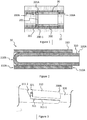
- the figure 1 partially and schematically shows a pipe 10 for filling a diesel tank of a motor vehicle.
- the tank comprises a key 20 mounted in the pipe 10.
- the polarizer 20 comprises a flexible part 200 in the form of a helix which is secured, at one 200A of its ends to the inlet of the pipe 10, and of which the other end 200B, located inside the pipe 10, is free to rotate and translate between a folded position and an unfolded position of the flexible part 200.
- the free end 200B comprises a pivoting movable flap 201, held closed by a return spring 201A and comprising a tongue 202 which, at rest in the “locked” position of the flap 201, is engaged in a stop 200-1 in order to prevent the opening of the shutter 201.
- the stop 200-1 is formed in the flexible part 200.
- the stop 200-1 could be formed in the body of the filling pipe 10.
- the keying 20 is configured to open the shutter 201 when a fuel dispensing gun of suitable diameter is inserted into said keying 20 and to keep the shutter 201 in a locked position when a fuel dispensing gun of insufficient diameter is inserted. through said polarizer 20.
- the device 30 according to the invention makes it possible to inhibit the keying device 20 so that an operator can insert a small diameter diesel gun and open the flap 201 of the keying device 20 in order to fill the tank.
- the inhibitor device 30 comprises a hollow tube 310 and a rod 320.
- the tube 310 is preferably made of a plastic material or of metal.
- the rod 320 is preferably made of a plastic material or of metal.
- the hollow tube 310 is open at its two ends 310A, 310B and is able to be inserted into the flexible part 200 of the keying device 20 so as to move the propeller in rotation, to move the tongue 202 out of the stop 200-1, and in translation, to open the movable pivoting shutter 201.
- the hollow tube 310 has the external diameter suitable for, when it is inserted into the keying device 20, coming into contact with the flexible part 200 and driving it in rotation and then in translation once the tongue 202 is out of its stop 200-1.
- the rod 320 is able to slide inside the tube 310 to a position of support of the shutter 201 in which the rod 320 supports the shutter 201 in an open position (illustrated in FIG. figure 11 ).
- the rod 320 is cylindrical of circular section and its external diameter is less than two millimeters, preferably less than one millimeter than the internal diameter of the tube so as to allow both a sliding of the rod 320 in the tube 310 and a retainer in the rod 320 in the tube 310.
- the tube 310 is configured to be withdrawn from the polarizer 20 while maintaining the rod 320 in its position for supporting the shutter 201 so, on the one hand, to allow the rotation of the flexible part towards its folded position and, of on the other hand, to maintain the shutter 201 in an open position.
- the tube 310 and the rod 320 are able to be manipulated by an operator in order to simultaneously allow the withdrawal of the tube 310 and the maintenance of the rod 320 in its position of support for the shutter 201.
- the rod 320 is configured to be withdrawn so that the tongue 202 of the shutter 201 comes to bear on the stopper 200-1 without however engaging with said stopper 200-1 so as to inhibit the polarizer 20.
- the rod 320 is able to be manipulated by an operator in order to allow its removal from the polarizer 20.
- the rod 320 comprises a proximal end 320A able to be manipulated by an operator and a distal end 320B able to push back the flap 201.
- the distal end 320B of the rod 320 has a rounded shape in order to limit friction and facilitate the opening of the shutter 201.
- the tube 310 comprises a proximal end 310A capable of being manipulated by an operator and a distal end 310B capable of being inserted into the key 20 in order to deactivate it.
- the tube 310 has a constant external diameter and a constant internal diameter.
- the external diameter and the diameter internal tube 310 could vary along tube 310 or more generally that any other suitable shape of tube 310 could be used provided that the tube 310 fulfills its function of inhibiting the helix 20 in the sense of the present invention.
- the rod 320 has a constant external diameter but it will be noted that in a variant, the external diameter of the rod 320 could vary along the tube 310 or more generally than any other suitable shape of the rod. 320 could be used on the condition that the rod 320 fulfills its function of inhibiting the keying device 20 with the helix within the meaning of the present invention. It will also be noted that the rod 320 can be hollow or solid without this limiting the scope of the present invention.
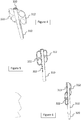
- the device 30 can further comprise means for blocking in translation the rod 320 relative to the tube 310.
- these blocking means comprise an L-shaped lumen 311 formed in the tube 310, the longest branch of the L 311-1 of which extends from the proximal end 310A of the tube 310.
- This lumen 311 makes it possible to receive a pin 321 extending from the external face of the rod 320 which can thus slide in the long branch of the lumen 311 from the proximal end 310A of the tube 310 to a position of blocking in translation defined by the short branch 311-2 of the lumen 311 which extends perpendicular to the long branch 311-1 of the lumen 311.
- the device 30 may comprise gripping means making it possible to easily move the rod 320 relative to the tube 310.
- the gripping means comprise a first handle 312 mounted on the tube 310 and a second handle 322 mounted on the rod 320 and passing through a slot 313 formed in the tube 310 so as to be able to be manipulated by an operator.
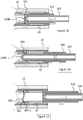
- a step E1 the hollow tube 310 containing the rod 320 is inserted into the flexible part 200 of the polarizer 20 so as to move the propeller on the one hand. in rotation to move the tongue 202 out of the stop 200-1 and on the other hand in translation to open the pivoting movable shutter 201 ( figures 8 to 10 ) up to a so-called “shutter 201 support” position in which the tube 310 and / or the rod 320 supports the shutter 201 in an open position.
- a step E2 the tube 310 is removed from the flexible part 200 while maintaining the rod 320 in the support position of the shutter 201 so, on the one hand, to allow the rotation of the flexible part 200 towards its folded position. and, on the other hand, to keep the shutter 201 in an unlocked position ( figure 11 ).
- a step E3 the rod 320 is removed from the keying device 20 so that the tongue 202 of the flap 201 comes to bear on the stopper 200-1 without however engaging with said stopper 200-1 so as to inhibit the keying device. 20.
- the method according to the invention thus advantageously makes it possible to disinhibit a coding device 20 with a propeller in a rapid, simple and effective manner.
Description
L'invention se rapporte au domaine de l'automobile et concerne plus particulièrement un dispositif et un procédé d'inhibition d'un détrompeur d'un réservoir de carburant d'un véhicule automobile. L'invention vise notamment à permettre le remplissage d'un réservoir de véhicule automobile avec du gazole délivré par un pistolet de distribution de faible diamètre.The invention relates to the field of the automobile and relates more particularly to a device and a method for inhibiting a foolproofing device of a fuel tank of a motor vehicle. The invention aims in particular to allow the filling of a motor vehicle tank with diesel fuel delivered by a dispensing gun of small diameter.
Dans le domaine de l'automobile, une norme ISO (International Organization for Standardization) préconise que les pistolets de distribution de gazole aient un diamètre de 24 mm et que les pistolets de distribution d'essence aient un diamètre de 21 mm de sorte qu'il ne soit pas mécaniquement possible d'introduire un pistolet de distribution de gazole dans la tubulure d'entrée d'un réservoir d'essence.In the automotive sector, an ISO (International Organization for Standardization) standard recommends that diesel fuel dispensing guns have a diameter of 24 mm and that fuel dispensing guns have a diameter of 21 mm so that it is not mechanically possible to introduce a diesel fuel dispensing gun into the inlet pipe of a petrol tank.
Afin d'éviter à l'inverse de permettre de remplir un réservoir de gazole avec de l'essence, il est connu d'équiper l'orifice de remplissage du réservoir de carburant d'un véhicule automobile à moteur Diesel d'un dispositif appelé « détrompeur ». Un tel détrompeur ne s'ouvre que si le pistolet est suffisamment large pour écarter des organes libérant un clapet afin de permettre l'introduction du pistolet et le remplissage du réservoir avec du gazole.In order to avoid, on the other hand, making it possible to fill a diesel tank with gasoline, it is known to equip the filler opening of the fuel tank of a diesel motor vehicle with a device called "Deceptive". Such a polarizing device only opens if the gun is large enough to separate members releasing a valve in order to allow the introduction of the gun and the filling of the tank with diesel fuel.
Dans certains pays, la norme ISO des diamètres des pistolets n'est pas toujours respectée et il arrive que les pistolets distribuant du gazole présentent un diamètre trop faible pour activer le détrompeur, c'est-à-dire pour écarter les organes de libération du clapet. Dans un tel cas, il n'est alors pas possible de réaliser un apport en gazole dans le réservoir, ce qui présente un inconvénient important.In some countries, the ISO standard for gun diameters is not always respected and it happens that the guns dispensing diesel have a diameter that is too small to activate the coding device, that is to say to move away the release members of the fuel. valve. In such a case, it is then not possible to add diesel fuel to the tank, which presents a significant drawback.
Afin de remédier à cet inconvénient, il est connu d'utiliser un accessoire permettant d'inhiber mécaniquement le détrompeur par blocage, sans dégradation pour ledit détrompeur et de manière totalement réversible. Cet accessoire, appelé « dispositif d'inhibition du détrompeur » ou « inhibiteur de détrompeur » se place dans la tubulure d'entrée du réservoir de gazole.In order to remedy this drawback, it is known practice to use an accessory making it possible to mechanically inhibit the foolproof device by blocking, without degradation for said foolproof device and in a completely reversible manner. This accessory, called a “foolproof inhibitor device” or “foolproof inhibitor” is placed in the inlet pipe of the diesel tank.
Une solution connue, décrite dans le document
Afin de résoudre au moins en partie ces inconvénients, une autre solution connue, décrite dans le document
Les détrompeurs à griffes présentant certains inconvénients, notamment en terme de blocage de composants dans la tubulure, il est connu d'utiliser aujourd'hui des détrompeurs dits « à hélice». Un détrompeur à hélice comporte une pièce flexible réalisée en un matériau plastique en forme d'hélice et qui est solidaire, en une de ses extrémités, de l'entrée de tubulure, et dont l'autre extrémité, située à l'intérieur de la tubulure de remplissage, est libre en rotation et translation. Cette extrémité libre porte un volet mobile pivotant, maintenu fermé par un ressort de rappel. Le volet mobile comporte une languette qui, au repos en position « verrouillée » est face à une butée formée dans le corps de tubulure permettant ainsi de bloquer le volet. Le diamètre de l'hélice est tel que lorsqu'on enfonce un pistolet à gazole de diamètre important, cela a pour effet d'élargir le corps de l'hélice et de provoquer une rotation de l'extrémité mobile, au fur et à mesure de l'enfoncement du pistolet, de sorte que la languette du volet ne se trouve plus en face de la butée permettant ainsi au volet de s'ouvrir avec l'enfoncement du pistolet. A contrario, si on enfonce un pistolet de faible diamètre, l'hélice ne se déforme pas et la languette du volet reste bloquée dans la butée formée dans le corps de tubulure, empêchant le remplissage avec le carburant distribué par un tel pistolet.Since the claw polarizers have certain drawbacks, in particular in terms of blocking of components in the tubing, it is known today to use so-called “helix” polarizers. A propeller polarizer comprises a flexible part made of a plastic material in the form of a helix and which is integral, at one of its ends, with the tubing inlet, and the other end of which is located inside the tube. filler pipe, is free to rotate and translate. This free end carries a pivoting movable shutter, held closed by a return spring. The movable shutter comprises a tongue which, at rest in the “locked” position, faces a stop formed in the tubing body, thus making it possible to block the shutter. The diameter of the propeller is such that when a large diameter diesel gun is pushed in, this has the effect of widening the body of the propeller and causing a rotation of the mobile end, as and when recess of the gun, so that the tab of the shutter is no longer opposite the stopper, allowing the shutter to open with the depression of the gun. Conversely, if a small diameter gun is pushed in, the propeller does not deform and the tab of the flap remains blocked in the stop formed in the pipe body, preventing filling with the fuel dispensed by such a gun.
La solution d'inhibiteur à tige décrite ci-avant pour un détrompeur à griffes ne s'avère pas adaptée pour un tel détrompeur à hélice. En effet, lors du retrait de la tige, il s'avère que la faible longueur de l'extrémité libre de la tige n'est pas suffisante pour permettre au volet de venir se placer en appui sur la butée sans verrouiller ledit volet.The rod inhibitor solution described above for a claw polarizer does not prove to be suitable for such a propeller polarizer. In fact, when the rod is withdrawn, it turns out that the short length of the free end of the rod is not sufficient to allow the shutter to come to rest on the stopper without locking said shutter.
Le document
L'invention vise donc à résoudre ces inconvénients en proposant une solution simple, fiable et efficace pour inhiber le détrompeur à hélice d'un réservoir de gazole.The invention therefore aims to resolve these drawbacks by proposing a simple, reliable and effective solution for inhibiting the propeller polarizer of a diesel tank.
A cette fin, l'invention a tout d'abord pour objet un dispositif d'inhibition d'un détrompeur de réservoir de carburant d'un véhicule automobile, ledit réservoir comprenant une tubulure de remplissage dans laquelle est monté ledit détrompeur, le détrompeur comprenant une pièce flexible en forme d'hélice qui est solidaire, en une de ses extrémités de l'entrée de tubulure, et dont l'autre extrémité, située à l'intérieur de la tubulure, est libre en rotation et translation entre une position repliée et une position dépliée de la pièce flexible, ladite extrémité libre comprenant un volet mobile pivotant, maintenu fermé par un ressort de rappel et comprenant une languette qui, au repos en position « verrouillée » du volet, est engagée dans une butée afin d'empêcher l'ouverture du volet.To this end, the invention first of all relates to a device for inhibiting a motor vehicle fuel tank foolproofing device, said tank comprising a filler pipe in which said foolproofing device is mounted, the polarizing device comprising a flexible part in the form of a helix which is integral, at one of its ends to the tubing inlet, and the other end of which, located inside the tubing, is free in rotation and translation between a folded position and an unfolded position of the flexible part, said free end comprising a pivoting movable shutter, held closed by a return spring and comprising a tongue which, at rest in the “locked” position of the shutter, is engaged in a stop in order to prevent the opening of the shutter.
Ledit dispositif est remarquable en ce qu'il comprend un tube creux, ouvert à ses deux extrémités et apte à être inséré dans la pièce flexible du détrompeur de manière à déplacer l'hélice en rotation, pour déplacer la languette hors de la butée, et en translation, pour ouvrir le volet mobile pivotant, et une tige apte à coulisser à l'intérieur dudit tube jusqu'à une position de support du volet dans laquelle la tige supporte le volet dans une position ouverte.Said device is remarkable in that it comprises a hollow tube, open at its two ends and capable of being inserted into the flexible part of the keying device so as to move the propeller in rotation, to move the tongue out of the stop, and in translation, to open the pivoting movable shutter, and a rod able to slide inside said tube to a position of support of the shutter in which the rod supports the shutter in an open position.
Le tube est configuré pour être retiré tout en maintenant la tige dans sa position de support du volet de sorte, d'une part, à permettre la rotation de la pièce flexible vers sa position repliée et, d'autre part, à maintenir le volet dans une position déverrouillée. La tige est configurée pour être retirée du détrompeur, après le retrait du tube de la pièce flexible, afin que la languette du volet vienne en appui sur la butée sans pour autant s'engager avec ladite butée de manière à inhiber le détrompeur.The tube is configured to be withdrawn while maintaining the rod in its position of support of the shutter so, on the one hand, to allow the rotation of the flexible part towards its folded position and, on the other hand, to maintain the shutter in an unlocked position. The rod is configured to be withdrawn from the keying device, after the tube has been withdrawn from the flexible part, so that the tab of the flap comes to bear on the stopper without however engaging with said stopper so as to inhibit the keying device.
Le dispositif selon l'invention est ainsi à la fois simple, efficace et aisé à utiliser pour inhiber un détrompeur à hélice. En particulier, la manipulation du dispositif est aisément réalisée en trois temps : l'insertion du tube et de la tige pour ouvrir le volet, le retrait du tube pour replier l'hélice en partie tout en maintenant la tige pour supporter le volet et le retrait de la tige afin que la languette du volet vienne en appui sur la butée de manière à laisser le volet ouvert pour permettre le remplissage du carburant par un pistolet de faible diamètre. On notera en outre que, partant de la solution décrite dans le document
Dans une forme de réalisation, la butée est formée dans le détrompeur, par exemple dans la pièce flexible.In one embodiment, the stopper is formed in the key, for example in the flexible part.
Dans une autre forme de réalisation, la butée est formée dans le corps de la tubulure de remplissage.In another embodiment, the stopper is formed in the body of the filler pipe.
Selon un aspect de l'invention, la tige comprend une extrémité proximale apte à être manipulée par un opérateur et une extrémité distale apte à repousser le volet.According to one aspect of the invention, the rod comprises a proximal end capable of being manipulated by an operator and a distal end capable of pushing back the flap.
De préférence, l'extrémité distale de la tige présente une forme arrondie, de préférence hémisphérique, afin de repousser le volet de manière efficace et sans l'endommager.Preferably, the distal end of the rod has a rounded shape, preferably hemispherical, in order to push back the flap effectively and without damaging it.
Dans une forme de réalisation, le dispositif comprend en outre des moyens de blocage en translation de la tige par rapport au tube afin de manipuler aisément le dispositif.In one embodiment, the device further comprises means for locking the rod in translation relative to the tube in order to easily handle the device.
Dans une autre forme de réalisation, le dispositif comprend des moyens de préhension permettant de déplacer la tige relativement au tube.In another embodiment, the device comprises gripping means making it possible to move the rod relative to the tube.
De manière avantageuse, les moyens de préhension comprennent une première poignée montée sur le tube et une deuxième poignée montée sur la tige afin de faire coulisser la tige aisément dans le tube.Advantageously, the gripping means comprise a first handle mounted on the tube and a second handle mounted on the rod in order to slide the rod easily in the tube.
Selon un aspect de l'invention, le tube est réalisé en un matériau plastique ou en métal.According to one aspect of the invention, the tube is made of a plastic material or of metal.
Selon un autre aspect de l'invention, la tige est réalisée en un matériau plastique ou en métal.According to another aspect of the invention, the rod is made of a plastic material or of metal.
L'invention concerne aussi l'utilisation d'un dispositif tel que présenté précédemment pour inhiber un détrompeur monté dans la tubulure de remplissage d'un réservoir de carburant d'un véhicule automobile.The invention also relates to the use of a device as presented above for inhibiting a polarizing device mounted in the filler neck of a fuel tank of a motor vehicle.
L'invention concerne également un procédé d'inhibition d'un détrompeur de réservoir de carburant d'un véhicule automobile, ledit réservoir comprenant une tubulure de remplissage dans laquelle est monté un détrompeur, ledit détrompeur comprenant une pièce flexible en forme d'hélice qui est solidaire, en une de ses extrémités de l'entrée de tubulure, et dont l'autre extrémité, située à l'intérieur de la tubulure, est libre en rotation et translation entre une position repliée et une position dépliée de la pièce flexible, ladite extrémité libre comprenant un volet mobile pivotant, maintenu fermé par un ressort de rappel et comprenant une languette qui, au repos en position « verrouillée » du volet, est engagée dans une butée formée dans le corps de la tubulure de remplissage afin d'empêcher l'ouverture du volet.The invention also relates to a method of inhibiting a motor vehicle fuel tank foolproofing device, said tank comprising a filler pipe in which a foolproofing device is mounted, said foolproofing device comprising a flexible part in the form of a propeller which is integral, at one of its ends to the tubing inlet, and the other end of which, located inside the tubing, is free in rotation and translation between a folded position and an unfolded position of the flexible part, said free end comprising a pivoting movable shutter, held closed by a return spring and comprising a tongue which, at rest in the “locked” position of the shutter, is engaged in a stop formed in the body of the filling pipe in order to prevent the opening of the shutter.
Ledit procédé étant remarquable en ce qu'il comprend :
- une étape d'insertion, dans la pièce flexible du détrompeur, d'un tube creux ouvert à ses deux extrémités, de manière à déplacer l'hélice en rotation, pour déplacer la languette hors de la butée, et en translation, pour ouvrir le volet mobile pivotant, ladite insertion étant réalisée jusqu'à une position de support du volet dans une position ouverte, une tige étant montée dans ledit tube creux,
- une étape de retrait du tube tout en maintenant la tige dans la position de support du volet de sorte, d'une part, à permettre la rotation de la pièce flexible vers sa position repliée et, d'autre part, à maintenir le volet dans une position déverrouillée,
- une étape de retrait de la tige afin que la languette du volet vienne en appui sur la butée de la tubulure sans pour autant s'engager avec ladite butée de manière à inhiber le détrompeur.
- a step of inserting, in the flexible part of the polarizer, a hollow tube open at its two ends, so as to move the propeller in rotation, to move the tongue out of the stop, and in translation, to open the pivoting movable shutter, said insertion being carried out up to a position of support of the shutter in an open position, a rod being mounted in said hollow tube,
- a step of removing the tube while maintaining the rod in the support position of the shutter so, on the one hand, to allow the rotation of the flexible part towards its folded position and, on the other hand, to keep the shutter in an unlocked position,
- a step of removing the rod so that the tongue of the flap comes to bear on the stop of the tubing without however engaging with said stop so as to inhibit the polarizing device.
D'autres caractéristiques et avantages de l'invention apparaîtront à la lecture de la description détaillée des modes de réalisation de l'invention, donnés à titre d'exemple uniquement, et en référence aux dessins qui illustrent :
- la
figure 1 , une vue en coupe d'un exemple de détrompeur à hélice monté dans une tubulure de réservoir, - la
figure 2 , une vue en coupe d'une forme de réalisation du dispositif d'inhibition selon l'invention, - la
figure 3 , un exemple de moyens de blocage, - la
figure 4 à 6 , des exemples de moyens de préhension, - la
figure 7 , un mode de réalisation du procédé selon l'invention, - les
figures 8 à 12 , les étapes illustrées du procédé de lafigure 7 utilisant le dispositif de lafigure 2 et le détrompeur de lafigure 1 .
- the
figure 1 , a sectional view of an example of a propeller polarizer mounted in a tank pipe, - the
figure 2 , a sectional view of an embodiment of the inhibition device according to the invention, - the
figure 3 , an example of blocking means, - the
figure 4 to 6 , examples of gripping means, - the
figure 7 , an embodiment of the method according to the invention, - the
figures 8 to 12 , the illustrated steps of the process offigure 7 using the device of thefigure 2 and the deceptive of thefigure 1 .
Dans ce qui va suivre, les modes de réalisation décrits s'attachent plus particulièrement à une mise en œuvre du dispositif d'inhibition d'un détrompeur selon l'invention dans un véhicule automobile. Cependant, toute mise en œuvre dans un contexte différent, en particulier dans tout type de véhicule, est également visée par la présente invention.In what follows, the embodiments described relate more particularly to an implementation of the device for inhibiting a keying device according to the invention in a motor vehicle. However, any implementation in a different context, in particular in any type of vehicle, is also targeted by the present invention.
La
Afin d'éviter l'introduction dans la tubulure d'un pistolet à essence de faible diamètre pour remplir le réservoir, le réservoir comprend un détrompeur 20 monté dans la tubulure 10.In order to avoid the introduction into the pipe of a gasoline gun of small diameter to fill the tank, the tank comprises a key 20 mounted in the
Le détrompeur 20 comprend une pièce 200 flexible en forme d'hélice qui est solidaire, en une 200A de ses extrémités de l'entrée de tubulure 10, et dont l'autre extrémité 200B, située à l'intérieur de la tubulure 10, est libre en rotation et translation entre une position repliée et une position dépliée de la pièce 200 flexible.The
L'extrémité libre 200B comprend un volet 201 mobile pivotant, maintenu fermé par un ressort de rappel 201A et comprenant une languette 202 qui, au repos en position « verrouillée » du volet 201, est engagée dans une butée 200-1 afin d'empêcher l'ouverture du volet 201. Dans l'exemple illustré à la
Le détrompeur 20 est configuré pour ouvrir le volet 201 lorsqu'un pistolet de distribution de gazole de diamètre adapté est inséré dans ledit détrompeur 20 et pour conserver le volet 201 dans une position verrouillée lorsqu'un pistolet de distribution de carburant de diamètre insuffisant est inséré à travers ledit détrompeur 20.The keying 20 is configured to open the
Le dispositif 30 selon l'invention permet d'inhiber le détrompeur 20 afin qu'un opérateur puisse insérer un pistolet à gazole de faible diamètre et ouvrir le volet 201 du détrompeur 20 pour remplir le réservoir.The
A cette fin, en référence à la
Le tube 310 creux est ouvert à ses deux extrémités 310A, 310B et est apte à être inséré dans la pièce flexible 200 du détrompeur 20 de manière à déplacer l'hélice en rotation, pour déplacer la languette 202 hors de la butée 200-1, et en translation, pour ouvrir le volet 201 mobile pivotant. En d'autres termes, le tube 310 creux possède le diamètre externe adapté pour, lorsqu'il est inséré dans le détrompeur 20, venir en contact avec la pièce 200 flexible et l'entrainer en rotation puis en translation une fois la languette 202 hors de sa butée 200-1.The
La tige 320 est apte à coulisser à l'intérieur du tube 310 jusqu'à une position de support du volet 201 dans laquelle la tige 320 supporte le volet 201 dans une position ouverte (illustrée à la
Comme illustré aux
La tige 320 est configurée pour être retirée afin que la languette 202 du volet 201 vienne en appui sur la butée 200-1 sans pour autant s'engager avec ladite butée 200-1 de manière à inhiber le détrompeur 20. En d'autres termes, la tige 320 est apte à être manipulée par un opérateur afin de permettre son retrait du détrompeur 20.The
Plus précisément, en référence à la
De la même façon, le tube 310 comprend une extrémité proximale 310A apte à être manipulée par un opérateur et une extrémité distale 310B apte être insérée dans le détrompeur 20 afin de le désactiver.Likewise, the
Dans l'exemple illustré, le tube 310 présente un diamètre externe constant et un diamètre interne constant. En variante, on notera que le diamètre externe et le diamètre interne du tube 310 pourraient varier le long du tube 310 ou plus généralement que toute autre forme adaptée du tube 310 pourrait être utilisée à la condition que le tube 310 remplisse sa fonction d'inhibition du détrompeur 20 à hélice au sens de la présente invention.In the example illustrated, the
De même, dans l'exemple illustré, la tige 320 présente un diamètre externe constant mais on notera qu'en variante, le diamètre externe de la tige 320 pourrait varier le long du tube 310 ou plus généralement que toute autre forme adaptée de la tige 320 pourrait être utilisée à la condition que la tige 320 remplisse sa fonction d'inhibition du détrompeur 20 à hélice au sens de la présente invention. On notera également que la tige 320 peut être creuse ou pleine sans que cela ne limite la portée de la présente invention.Likewise, in the example illustrated, the
De préférence, le dispositif 30 peut comprendre en outre des moyens de blocage en translation de la tige 320 par rapport au tube 310.Preferably, the
Dans une forme de réalisation illustrée à la
Dans une forme de réalisation illustrée aux
L'invention va maintenant être décrite dans sa mise en œuvre en référence aux
Tout d'abord, dans une étape E1, on insère le tube 310 creux contenant la tige 320 dans la pièce 200 flexible du détrompeur 20 de manière à déplacer l'hélice d'une part en rotation pour déplacer la languette 202 hors de la butée 200-1 et d'autre part en translation pour ouvrir le volet 201 mobile pivotant (
En variante, on pourrait insérer le tube 310 d'abord dans le détrompeur 20 puis faire glisser la tige 320 à l'intérieur du tube 310 afin qu'elle coulisse jusqu'à une position dite « de support du volet 201 » dans laquelle le tube 10 et/ou la tige 320 supporte(nt) le volet 201 dans une position ouverte.As a variant, one could insert the
Dans une étape E2, on retire le tube 310 de la pièce 200 flexible tout en maintenant la tige 320 dans la position de support du volet 201 de sorte, d'une part, à permettre la rotation de la pièce 200 flexible vers sa position repliée et, d'autre part, à maintenir le volet 201 dans une position déverrouillée (
Enfin, dans une étape E3, on retire la tige 320 du détrompeur 20 afin que la languette 202 du volet 201 vienne en appui sur la butée 200-1 sans pour autant s'engager avec ladite butée 200-1 de manière à inhiber le détrompeur 20.Finally, in a step E3, the
Le procédé selon l'invention permet ainsi avantageusement de désinhiber un détrompeur 20 à hélice de manière rapide, simple et efficace.The method according to the invention thus advantageously makes it possible to disinhibit a
Claims (10)
- Device (30) inhibition of a polarizer (20) A fuel tank of a motor vehicle, said tank comprising a pipe (10) of filling in which is mounted said polarizer (20), the actuator (20) comprising a flexible part (200) in the form of a helix which is secured, at one (200A) of its ends, to the inlet of the tubing (10), and of which the other end (200B), located inside the tubing (10), is free to rotate and
translate between a folded position and an unfolded position of the flexible part (200), said free end (200B) comprising a pivoting movable flap (201), held closed by a return spring and comprising a tongue (202) which, at rest in "position locked " of the flap (201), is engaged in an abutment (200-1) to prevent the opening of the flap (201), said device (30) being characterized in that it comprises :- a hollow tube (310) open at its two ends (310A, 310B) capable of being inserted into the flexible part (200) of the keying device (20) so as to move the propeller in rotation, to move the tongue (202) out of the stop (200-1), and in translation, to open the movable pivoting shutter (201),- a rod (320) able to slide inside said tube (310) to a position of support for the shutter (201) in which the rod (320) supports the shutter (201) in an open position,the tube (310) being configured to be withdrawn while maintaining the rod (320) in its position of support of the shutter (201) so, on the one hand, to allow the rotation of the flexible part (200) towards its folded position and, on the other hand, to maintain the shutter (201) in an unlocked position , the rod (320) being configured to be withdrawn from the polarizer (20), after the tube (310) has been withdrawn from the part (200) flexible, so that the tongue (202) of the shutter (201) comes to bear on the stopper (200-1) without however engaging with said stopper (200-1) so as to inhibit the polarizer (20) . - Device (30) according to the preceding claim, wherein the rod (320) include an d a proximal end (320A) adapted to be manipulated by an operator and a distal end (320B) adapted to push the flap (201).
- Device (30) according to the preceding claim, in which the distal end (320B) of the rod (320) has a rounded shape.
- Device (30) according to one of the preceding claims, further comprising locking means (311, 321) in translation of the rod (320) relative to the tube (310).
- Device (30) according to one of the preceding claims, further comprising gripping means (312, 322) for moving the rod (320) relative to the tube (310).
- Device (30) according to the preceding claim, in which the gripping means comprise a first handle (312) mounted on the tube (310) and a second handle (322) mounted on the rod (320).
- Device according to one of the preceding claims wherein the tube (310) is made of a plastic material or metal.
- Device according to one of the preceding claims, in which the rod (320) is made of a plastic material or of metal.
- Use of a device (30) according to one of the preceding claims for inhibiting a polarizer (20) mounted in the manifold (10) for filling a fuel tank of a motor vehicle.
- A method of inhibiting a polarizing device (20) of a motor vehicle fuel tank, said tank comprising a filler pipe (10) in which a polarizing device (20) is mounted, said polarizing device (20) comprising a part (200) flexible in the form of a helix which is secured, at one (200A) of its ends to the inlet of the tubing (10), and the other end of which (200B), located inside the tubing (10)), is free to rotate and translate between a folded position and an unfolded position of the flexible part (200), said free end (200B) comprising a pivoting movable flap (201), held closed by a return spring and comprising a tongue (202) which, at rest in the " locked " position of the shutter (201), is engaged in a stop (200-1) in order to prevent the opening of the shutter (201), said method being characterized in that it includes :- a step (E1) of inserting, in the flexible part (200) of the
polarizer (20), a hollow tube (310) open at its two ends (310A, 310B), so as to move the propeller in rotation, to move the tongue (202) out of the stop (200-1), and in translation, to open the pivoting movable shutter (201), said insertion being carried out to a support position of the shutter (201) in an open position, a rod (320) being mounted in said hollow tube (310),- a step (E2) of removing the tube (310) while maintaining the
rod (320) in the support position of the shutter (201) so, on the one hand, to allow the rotation of the part (200) flexible to its folded position and, on the other hand, to maintain the shutter (201) in an unlocked position,- a step (E3) of removing the rod (320) so that the tongue (202) of the
flap (201) comes to bear on the stopper (200-1) without thereby engaging with said stopper (200-1) so as to inhibit the polarizer (20).
Applications Claiming Priority (2)
| Application Number | Priority Date | Filing Date | Title |
|---|---|---|---|
| FR1755269A FR3067297B1 (en) | 2017-06-13 | 2017-06-13 | DEVICE FOR INHIBITING A RESERVOIR DETROMPER |
| PCT/FR2018/051269 WO2018229383A1 (en) | 2017-06-13 | 2018-06-01 | Device for overriding a misfuelling prevention device |
Publications (2)
| Publication Number | Publication Date |
|---|---|
| EP3638532A1 EP3638532A1 (en) | 2020-04-22 |
| EP3638532B1 true EP3638532B1 (en) | 2021-08-04 |
Family
ID=59649894
Family Applications (1)
| Application Number | Title | Priority Date | Filing Date |
|---|---|---|---|
| EP18737335.2A Active EP3638532B1 (en) | 2017-06-13 | 2018-06-01 | Device for overriding a misfuelling prevention device |
Country Status (4)
| Country | Link |
|---|---|
| EP (1) | EP3638532B1 (en) |
| FR (1) | FR3067297B1 (en) |
| MA (1) | MA49389A (en) |
| WO (1) | WO2018229383A1 (en) |
Family Cites Families (6)
| Publication number | Priority date | Publication date | Assignee | Title |
|---|---|---|---|---|
| FR2905638B1 (en) * | 2006-09-13 | 2008-11-28 | I T W De France Soc Par Action | TIP FOR FILLING A TANK |
| JP4892398B2 (en) * | 2007-04-23 | 2012-03-07 | 本田技研工業株式会社 | Filler pipe filler port structure |
| FR2963911B1 (en) | 2010-08-19 | 2012-09-28 | Peugeot Citroen Automobiles Sa | METHOD FOR TEMPORARILY DEACTIVATING A MECHANICAL DETOMPER FOR A FUEL TANK AND ASSOCIATED DEVICE |
| FR2963912B1 (en) | 2010-08-19 | 2012-09-21 | Peugeot Citroen Automobiles Sa | METHOD FOR DEACTIVATION OF A MECHANICAL DETOMPER FOR A FUEL TANK |
| KR101481272B1 (en) * | 2013-05-28 | 2015-01-09 | 현대자동차주식회사 | Filler neck device for preventing fuel from mixing |
| FR3018479B1 (en) * | 2014-03-14 | 2016-04-01 | Microtechnic Sa | DEVIATION DEVICE FOR FUEL ARRIVAL PIPE OF A TANK OF A VEHICLE |
-
2017
- 2017-06-13 FR FR1755269A patent/FR3067297B1/en not_active Expired - Fee Related
-
2018
- 2018-06-01 MA MA049389A patent/MA49389A/en unknown
- 2018-06-01 EP EP18737335.2A patent/EP3638532B1/en active Active
- 2018-06-01 WO PCT/FR2018/051269 patent/WO2018229383A1/en unknown
Also Published As
| Publication number | Publication date |
|---|---|
| EP3638532A1 (en) | 2020-04-22 |
| WO2018229383A1 (en) | 2018-12-20 |
| FR3067297A1 (en) | 2018-12-14 |
| MA49389A (en) | 2020-04-22 |
| FR3067297B1 (en) | 2019-07-19 |
Similar Documents
| Publication | Publication Date | Title |
|---|---|---|
| FR2863034A1 (en) | QUICK COUPLING | |
| EP2079646B1 (en) | Fluid product dispensing device | |
| EP2439440B1 (en) | Coupling device with locking by threaded clamps and coupling including such a device | |
| FR2903164A1 (en) | Quick coupler for vehicle, has retaining unit displaced automatically by displacement mechanism toward engagement position and engaged with annular engagement projection, when projection reaches connection position | |
| EP1328750A1 (en) | Connecting device comprising means for instantaneous connection of a pipe end to a member and means for protecting the connection | |
| EP1853842A1 (en) | Quick coupling for the joining of two pressurised gas lines | |
| FR2827364A1 (en) | Quick-fit coupling for fluid circuit has lock ring inside female component to ensure correct fitting and retention of male component | |
| EP1580358B1 (en) | Protection for driving device for latch actuating via a lock | |
| EP3638532B1 (en) | Device for overriding a misfuelling prevention device | |
| EP2101097B1 (en) | Connection device for fluid transfer, circuit including said device and assembly/disassembly method thereof | |
| EP3377437B1 (en) | Device for ejecting a cork from a corkscrew and corkscrew provided with such an ejection device | |
| EP2918438B1 (en) | Misfuel inhibiting device for a fuel inlet pipe of a vehicle tank | |
| EP0374493A1 (en) | Gas bottle valve | |
| FR3067987B1 (en) | DETRUDING DEVICE FOR A FUEL FILLING DUCT OF A VEHICLE TANK AND VEHICLE COMPRISING SAID DEVICE | |
| WO2012022872A1 (en) | Method for temporarily deactivating a mechanical foolproof device for a fuel tank, and associated device | |
| EP2282805A1 (en) | Improved connector for medical use | |
| FR2920804A1 (en) | PROVISIONAL CLEARANCE DEVICE PROVIDED WITH LOCKING MEANS | |
| FR2963912A1 (en) | Method for deactivating mechanical guide pin of fuel tank of vehicle i.e. motor vehicle, involves installing sleeve in conduit in predetermined position in which sleeve prevents closing of valve, and performing shrinking operation of tool | |
| EP3999765B1 (en) | Compact and demountable fluid connection device | |
| BE680118A (en) | ||
| FR2916389A1 (en) | Safety device for e.g. motor vehicle's diesel filling pipe, has pins sliding for being retracted inside housings after force is exerted by end of nozzle with specific diameter, where spacing of pins allows swing of valve and access to tank | |
| WO2000014444A1 (en) | Single-piece fast connector with reduced space requirement | |
| WO2023118108A1 (en) | Aseptic coupling device for a tube | |
| WO2023089262A1 (en) | Assembly comprising an interbody cage and the placement device therefor | |
| FR3053714A1 (en) | SEALING DEVICE COMPRISING A LOCKING BUTTON TO BE ACTIVATED IN A SEALED STATE OF THE SEALING DEVICE |
Legal Events
| Date | Code | Title | Description |
|---|---|---|---|
| STAA | Information on the status of an ep patent application or granted ep patent |
Free format text: STATUS: UNKNOWN |
|
| STAA | Information on the status of an ep patent application or granted ep patent |
Free format text: STATUS: THE INTERNATIONAL PUBLICATION HAS BEEN MADE |
|
| PUAI | Public reference made under article 153(3) epc to a published international application that has entered the european phase |
Free format text: ORIGINAL CODE: 0009012 |
|
| STAA | Information on the status of an ep patent application or granted ep patent |
Free format text: STATUS: REQUEST FOR EXAMINATION WAS MADE |
|
| 17P | Request for examination filed |
Effective date: 20191121 |
|
| AK | Designated contracting states |
Kind code of ref document: A1 Designated state(s): AL AT BE BG CH CY CZ DE DK EE ES FI FR GB GR HR HU IE IS IT LI LT LU LV MC MK MT NL NO PL PT RO RS SE SI SK SM TR |
|
| AX | Request for extension of the european patent |
Extension state: BA ME |
|
| DAX | Request for extension of the european patent (deleted) | ||
| RAV | Requested validation state of the european patent: fee paid |
Extension state: MA Effective date: 20191121 |
|
| RAP1 | Party data changed (applicant data changed or rights of an application transferred) |
Owner name: PSA AUTOMOBILES SA |
|
| GRAP | Despatch of communication of intention to grant a patent |
Free format text: ORIGINAL CODE: EPIDOSNIGR1 |
|
| STAA | Information on the status of an ep patent application or granted ep patent |
Free format text: STATUS: GRANT OF PATENT IS INTENDED |
|
| INTG | Intention to grant announced |
Effective date: 20210204 |
|
| GRAS | Grant fee paid |
Free format text: ORIGINAL CODE: EPIDOSNIGR3 |
|
| GRAA | (expected) grant |
Free format text: ORIGINAL CODE: 0009210 |
|
| STAA | Information on the status of an ep patent application or granted ep patent |
Free format text: STATUS: THE PATENT HAS BEEN GRANTED |
|
| AK | Designated contracting states |
Kind code of ref document: B1 Designated state(s): AL AT BE BG CH CY CZ DE DK EE ES FI FR GB GR HR HU IE IS IT LI LT LU LV MC MK MT NL NO PL PT RO RS SE SI SK SM TR |
|
| REG | Reference to a national code |
Ref country code: GB Ref legal event code: FG4D Free format text: NOT ENGLISH |
|
| REG | Reference to a national code |
Ref country code: DE Ref legal event code: R084 Ref document number: 602018021257 Country of ref document: DE |
|
| REG | Reference to a national code |
Ref country code: AT Ref legal event code: REF Ref document number: 1416644 Country of ref document: AT Kind code of ref document: T Effective date: 20210815 |
|
| REG | Reference to a national code |
Ref country code: CH Ref legal event code: EP |
|
| REG | Reference to a national code |
Ref country code: DE Ref legal event code: R096 Ref document number: 602018021257 Country of ref document: DE |
|
| REG | Reference to a national code |
Ref country code: IE Ref legal event code: FG4D Free format text: LANGUAGE OF EP DOCUMENT: FRENCH |
|
| REG | Reference to a national code |
Ref country code: GB Ref legal event code: 746 Effective date: 20210910 |
|
| REG | Reference to a national code |
Ref country code: LT Ref legal event code: MG9D |
|
| REG | Reference to a national code |
Ref country code: NL Ref legal event code: MP Effective date: 20210804 |
|
| REG | Reference to a national code |
Ref country code: AT Ref legal event code: MK05 Ref document number: 1416644 Country of ref document: AT Kind code of ref document: T Effective date: 20210804 |
|
| PG25 | Lapsed in a contracting state [announced via postgrant information from national office to epo] |
Ref country code: BG Free format text: LAPSE BECAUSE OF FAILURE TO SUBMIT A TRANSLATION OF THE DESCRIPTION OR TO PAY THE FEE WITHIN THE PRESCRIBED TIME-LIMIT Effective date: 20211104 Ref country code: AT Free format text: LAPSE BECAUSE OF FAILURE TO SUBMIT A TRANSLATION OF THE DESCRIPTION OR TO PAY THE FEE WITHIN THE PRESCRIBED TIME-LIMIT Effective date: 20210804 Ref country code: LT Free format text: LAPSE BECAUSE OF FAILURE TO SUBMIT A TRANSLATION OF THE DESCRIPTION OR TO PAY THE FEE WITHIN THE PRESCRIBED TIME-LIMIT Effective date: 20210804 Ref country code: PT Free format text: LAPSE BECAUSE OF FAILURE TO SUBMIT A TRANSLATION OF THE DESCRIPTION OR TO PAY THE FEE WITHIN THE PRESCRIBED TIME-LIMIT Effective date: 20211206 Ref country code: NO Free format text: LAPSE BECAUSE OF FAILURE TO SUBMIT A TRANSLATION OF THE DESCRIPTION OR TO PAY THE FEE WITHIN THE PRESCRIBED TIME-LIMIT Effective date: 20211104 Ref country code: HR Free format text: LAPSE BECAUSE OF FAILURE TO SUBMIT A TRANSLATION OF THE DESCRIPTION OR TO PAY THE FEE WITHIN THE PRESCRIBED TIME-LIMIT Effective date: 20210804 Ref country code: ES Free format text: LAPSE BECAUSE OF FAILURE TO SUBMIT A TRANSLATION OF THE DESCRIPTION OR TO PAY THE FEE WITHIN THE PRESCRIBED TIME-LIMIT Effective date: 20210804 Ref country code: FI Free format text: LAPSE BECAUSE OF FAILURE TO SUBMIT A TRANSLATION OF THE DESCRIPTION OR TO PAY THE FEE WITHIN THE PRESCRIBED TIME-LIMIT Effective date: 20210804 Ref country code: RS Free format text: LAPSE BECAUSE OF FAILURE TO SUBMIT A TRANSLATION OF THE DESCRIPTION OR TO PAY THE FEE WITHIN THE PRESCRIBED TIME-LIMIT Effective date: 20210804 Ref country code: SE Free format text: LAPSE BECAUSE OF FAILURE TO SUBMIT A TRANSLATION OF THE DESCRIPTION OR TO PAY THE FEE WITHIN THE PRESCRIBED TIME-LIMIT Effective date: 20210804 |
|
| PG25 | Lapsed in a contracting state [announced via postgrant information from national office to epo] |
Ref country code: PL Free format text: LAPSE BECAUSE OF FAILURE TO SUBMIT A TRANSLATION OF THE DESCRIPTION OR TO PAY THE FEE WITHIN THE PRESCRIBED TIME-LIMIT Effective date: 20210804 Ref country code: LV Free format text: LAPSE BECAUSE OF FAILURE TO SUBMIT A TRANSLATION OF THE DESCRIPTION OR TO PAY THE FEE WITHIN THE PRESCRIBED TIME-LIMIT Effective date: 20210804 Ref country code: GR Free format text: LAPSE BECAUSE OF FAILURE TO SUBMIT A TRANSLATION OF THE DESCRIPTION OR TO PAY THE FEE WITHIN THE PRESCRIBED TIME-LIMIT Effective date: 20211105 |
|
| PG25 | Lapsed in a contracting state [announced via postgrant information from national office to epo] |
Ref country code: NL Free format text: LAPSE BECAUSE OF FAILURE TO SUBMIT A TRANSLATION OF THE DESCRIPTION OR TO PAY THE FEE WITHIN THE PRESCRIBED TIME-LIMIT Effective date: 20210804 |
|
| PG25 | Lapsed in a contracting state [announced via postgrant information from national office to epo] |
Ref country code: DK Free format text: LAPSE BECAUSE OF FAILURE TO SUBMIT A TRANSLATION OF THE DESCRIPTION OR TO PAY THE FEE WITHIN THE PRESCRIBED TIME-LIMIT Effective date: 20210804 |
|
| REG | Reference to a national code |
Ref country code: DE Ref legal event code: R097 Ref document number: 602018021257 Country of ref document: DE |
|
| PG25 | Lapsed in a contracting state [announced via postgrant information from national office to epo] |
Ref country code: SM Free format text: LAPSE BECAUSE OF FAILURE TO SUBMIT A TRANSLATION OF THE DESCRIPTION OR TO PAY THE FEE WITHIN THE PRESCRIBED TIME-LIMIT Effective date: 20210804 Ref country code: SK Free format text: LAPSE BECAUSE OF FAILURE TO SUBMIT A TRANSLATION OF THE DESCRIPTION OR TO PAY THE FEE WITHIN THE PRESCRIBED TIME-LIMIT Effective date: 20210804 Ref country code: RO Free format text: LAPSE BECAUSE OF FAILURE TO SUBMIT A TRANSLATION OF THE DESCRIPTION OR TO PAY THE FEE WITHIN THE PRESCRIBED TIME-LIMIT Effective date: 20210804 Ref country code: EE Free format text: LAPSE BECAUSE OF FAILURE TO SUBMIT A TRANSLATION OF THE DESCRIPTION OR TO PAY THE FEE WITHIN THE PRESCRIBED TIME-LIMIT Effective date: 20210804 Ref country code: CZ Free format text: LAPSE BECAUSE OF FAILURE TO SUBMIT A TRANSLATION OF THE DESCRIPTION OR TO PAY THE FEE WITHIN THE PRESCRIBED TIME-LIMIT Effective date: 20210804 Ref country code: AL Free format text: LAPSE BECAUSE OF FAILURE TO SUBMIT A TRANSLATION OF THE DESCRIPTION OR TO PAY THE FEE WITHIN THE PRESCRIBED TIME-LIMIT Effective date: 20210804 |
|
| PLBE | No opposition filed within time limit |
Free format text: ORIGINAL CODE: 0009261 |
|
| STAA | Information on the status of an ep patent application or granted ep patent |
Free format text: STATUS: NO OPPOSITION FILED WITHIN TIME LIMIT |
|
| 26N | No opposition filed |
Effective date: 20220506 |
|
| PG25 | Lapsed in a contracting state [announced via postgrant information from national office to epo] |
Ref country code: IT Free format text: LAPSE BECAUSE OF FAILURE TO SUBMIT A TRANSLATION OF THE DESCRIPTION OR TO PAY THE FEE WITHIN THE PRESCRIBED TIME-LIMIT Effective date: 20210804 |
|
| PG25 | Lapsed in a contracting state [announced via postgrant information from national office to epo] |
Ref country code: SI Free format text: LAPSE BECAUSE OF FAILURE TO SUBMIT A TRANSLATION OF THE DESCRIPTION OR TO PAY THE FEE WITHIN THE PRESCRIBED TIME-LIMIT Effective date: 20210804 |
|
| PG25 | Lapsed in a contracting state [announced via postgrant information from national office to epo] |
Ref country code: MC Free format text: LAPSE BECAUSE OF FAILURE TO SUBMIT A TRANSLATION OF THE DESCRIPTION OR TO PAY THE FEE WITHIN THE PRESCRIBED TIME-LIMIT Effective date: 20210804 |
|
| REG | Reference to a national code |
Ref country code: CH Ref legal event code: PL |
|
| REG | Reference to a national code |
Ref country code: BE Ref legal event code: MM Effective date: 20220630 |
|
| PG25 | Lapsed in a contracting state [announced via postgrant information from national office to epo] |
Ref country code: LU Free format text: LAPSE BECAUSE OF NON-PAYMENT OF DUE FEES Effective date: 20220601 Ref country code: LI Free format text: LAPSE BECAUSE OF NON-PAYMENT OF DUE FEES Effective date: 20220630 Ref country code: IE Free format text: LAPSE BECAUSE OF NON-PAYMENT OF DUE FEES Effective date: 20220601 Ref country code: CH Free format text: LAPSE BECAUSE OF NON-PAYMENT OF DUE FEES Effective date: 20220630 |
|
| PG25 | Lapsed in a contracting state [announced via postgrant information from national office to epo] |
Ref country code: BE Free format text: LAPSE BECAUSE OF NON-PAYMENT OF DUE FEES Effective date: 20220630 |
|
| PGFP | Annual fee paid to national office [announced via postgrant information from national office to epo] |
Ref country code: FR Payment date: 20230523 Year of fee payment: 6 Ref country code: DE Payment date: 20230523 Year of fee payment: 6 |
|
| PGFP | Annual fee paid to national office [announced via postgrant information from national office to epo] |
Ref country code: GB Payment date: 20230523 Year of fee payment: 6 |