EP3637906B1 - Verfahren und vorrichtung für ressourcenzuweisung - Google Patents
Verfahren und vorrichtung für ressourcenzuweisung Download PDFInfo
- Publication number
- EP3637906B1 EP3637906B1 EP18795163.7A EP18795163A EP3637906B1 EP 3637906 B1 EP3637906 B1 EP 3637906B1 EP 18795163 A EP18795163 A EP 18795163A EP 3637906 B1 EP3637906 B1 EP 3637906B1
- Authority
- EP
- European Patent Office
- Prior art keywords
- scheduling group
- resource allocation
- scheduling
- radio resources
- groups
- Prior art date
- Legal status (The legal status is an assumption and is not a legal conclusion. Google has not performed a legal analysis and makes no representation as to the accuracy of the status listed.)
- Active
Links
Images


Classifications
-
- H—ELECTRICITY
- H04—ELECTRIC COMMUNICATION TECHNIQUE
- H04L—TRANSMISSION OF DIGITAL INFORMATION, e.g. TELEGRAPHIC COMMUNICATION
- H04L5/00—Arrangements affording multiple use of the transmission path
- H04L5/003—Arrangements for allocating sub-channels of the transmission path
- H04L5/0032—Distributed allocation, i.e. involving a plurality of allocating devices, each making partial allocation
- H04L5/0035—Resource allocation in a cooperative multipoint environment
-
- H—ELECTRICITY
- H04—ELECTRIC COMMUNICATION TECHNIQUE
- H04B—TRANSMISSION
- H04B7/00—Radio transmission systems, i.e. using radiation field
- H04B7/02—Diversity systems; Multi-antenna system, i.e. transmission or reception using multiple antennas
- H04B7/022—Site diversity; Macro-diversity
- H04B7/024—Co-operative use of antennas of several sites, e.g. in co-ordinated multipoint or co-operative multiple-input multiple-output [MIMO] systems
-
- H—ELECTRICITY
- H04—ELECTRIC COMMUNICATION TECHNIQUE
- H04B—TRANSMISSION
- H04B7/00—Radio transmission systems, i.e. using radiation field
- H04B7/02—Diversity systems; Multi-antenna system, i.e. transmission or reception using multiple antennas
- H04B7/04—Diversity systems; Multi-antenna system, i.e. transmission or reception using multiple antennas using two or more spaced independent antennas
- H04B7/06—Diversity systems; Multi-antenna system, i.e. transmission or reception using multiple antennas using two or more spaced independent antennas at the transmitting station
- H04B7/0697—Diversity systems; Multi-antenna system, i.e. transmission or reception using multiple antennas using two or more spaced independent antennas at the transmitting station using spatial multiplexing
-
- H—ELECTRICITY
- H04—ELECTRIC COMMUNICATION TECHNIQUE
- H04L—TRANSMISSION OF DIGITAL INFORMATION, e.g. TELEGRAPHIC COMMUNICATION
- H04L5/00—Arrangements affording multiple use of the transmission path
- H04L5/003—Arrangements for allocating sub-channels of the transmission path
- H04L5/0053—Allocation of signalling, i.e. of overhead other than pilot signals
-
- H—ELECTRICITY
- H04—ELECTRIC COMMUNICATION TECHNIQUE
- H04W—WIRELESS COMMUNICATION NETWORKS
- H04W72/00—Local resource management
- H04W72/50—Allocation or scheduling criteria for wireless resources
- H04W72/53—Allocation or scheduling criteria for wireless resources based on regulatory allocation policies
-
- H—ELECTRICITY
- H04—ELECTRIC COMMUNICATION TECHNIQUE
- H04W—WIRELESS COMMUNICATION NETWORKS
- H04W72/00—Local resource management
- H04W72/50—Allocation or scheduling criteria for wireless resources
- H04W72/535—Allocation or scheduling criteria for wireless resources based on resource usage policies
-
- H—ELECTRICITY
- H04—ELECTRIC COMMUNICATION TECHNIQUE
- H04W—WIRELESS COMMUNICATION NETWORKS
- H04W72/00—Local resource management
- H04W72/04—Wireless resource allocation
- H04W72/044—Wireless resource allocation based on the type of the allocated resource
- H04W72/0453—Resources in frequency domain, e.g. a carrier in FDMA
-
- H—ELECTRICITY
- H04—ELECTRIC COMMUNICATION TECHNIQUE
- H04W—WIRELESS COMMUNICATION NETWORKS
- H04W72/00—Local resource management
- H04W72/20—Control channels or signalling for resource management
- H04W72/23—Control channels or signalling for resource management in the downlink direction of a wireless link, i.e. towards a terminal
Definitions
- the present disclosure relates to the field of communications, for example, a resource allocation method and apparatus, and a storage medium.
- LTE Long Term Evolution
- LTE-A Long Term Evolution-Advanced
- CoMP Coordinated Multi-Point
- the CoMP technology is classified into three types: Joint Transmission (JT), Dynamic Node Selection (DPS)/Dynamic Node Blanking (DPB), and Coordinated Scheduling Coordinated Beamforming (CSCB).
- JT Joint Transmission
- DPS Dynamic Node Selection
- DPB Dynamic Node Blanking
- CSCB Coordinated Scheduling Coordinated Beamforming
- the sending end uniformly indicates radio transmission resource blocks (RBs) occupied by the currently transmitted data information group (maximum 2 data information groups) by configuring the resource-allocation-related signaling (resource allocation field) in the downlink control information (DCI) in the physical downlink control channel (PDCCH)/enhanced physical downlink control channel (EPDCCH).
- RBs radio transmission resource blocks
- DCI downlink control information
- PDCCH physical downlink control channel
- EPDCCH enhanced physical downlink control channel
- Embodiments of the present application provide a resource allocation method to solve at least the problem in the related art that the system performance is severely limited because multiple data information groups can only be transmitted by the serving cell and the cooperative cell on the same frequency-domain resources during JT transmission.
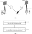
- FIG. 2 is a flowchart of a resource allocation method according to embodiments of the present application. As shown in FIG. 2 , the resource allocation method includes steps 102 and 104 described below.
- a base station determines a resource allocation mode used by n data information groups.
- the resource allocation mode includes a mode one and a mode two, the mode one is that radio resources used by the n data information groups are completely overlapped and the mode two is that the radio resources used by the n data information groups are completely non-overlapped, and n is an integer greater than 1.
- step 104 the base station performs resource allocation by using the determined resource allocation mode.
- each of the n data information groups includes at least one of a codeword (CW), a transport block (TB), a code block (CB), a code block group (CBG) or a code block group set (CBG set).
- CW codeword
- TB transport block
- CB code block
- CBG code block group
- CBG set code block group set
- the base station determines a resource allocation mode used by multiple data information groups.
- Two resource allocation modes are provided. One mode is that radio resources used by the multiple data information groups are completely overlapped and the other mode is that the radio resources used by the multiple data information groups are completely non-overlapped.
- the base station performs resource allocation by using the determined resource allocation mode.
- the method further includes that the base station sends a signaling message to a terminal.
- the signaling message is used for indicating the resource allocation mode used by the base station and the signaling message includes at least one of radio resource control (RRC) signaling or downlink control information (DCI) signaling.
- RRC radio resource control
- DCI downlink control information
- the base station when the base station performs resource allocation by using the mode two, that is, when the radio resources used by the n data information groups are completely non-overlapped, different data information groups have different scheduling groups and an offset relationship exists between different scheduling groups.
- the signaling message is further used for indicating at least one of (i) the start position of a first scheduling group and the length of radio resources continuously occupied by the first scheduling group, (ii) the offset relationship between different scheduling groups or (iii) the index of the offset relationship between different scheduling groups.
- the scheduling groups are in one-to-one correspondence with the data information groups and the scheduling groups are used for indicating radio resources actually scheduled for use by the data information groups.
- the (m + 1)th scheduling group has the offset relationship with one or more of the first scheduling group to the mth scheduling group, where 1 ⁇ m ⁇ n - 1.
- the offset relationship include the cases described below.
- a first offset value exists between the start position of radio resources continuously occupied by the (m + 1)th scheduling group and the end position of radio resources continuously occupied by one or more of the first scheduling group to the mth scheduling group.
- a second offset value exists between the end position of the radio resources continuously occupied by the (m + 1)th scheduling group and the start position of the radio resources continuously occupied by one or more of the first scheduling group to the mth scheduling group.
- a third offset value exists between the end position of radio resources continuously occupied by the (m + 1)th scheduling group and the end position of radio resources continuously occupied by one or more of the first scheduling group to the mth scheduling group.
- a fourth offset value exists between the start position of the radio resources continuously occupied by the (m + 1)th scheduling group and the start position of the radio resources continuously occupied by one or more of the first scheduling group to the mth scheduling group.
- the first offset value, the second offset value, the third offset value and the fourth offset value are determined according to radio resources actually used by each of the n data information groups and is indicated by the signaling message sent by the base station to the terminal.
- the offset value is indicated or jointly indicated by some bits of resource allocation field in DCI. The joint indication here is understood as using one or more bits to indicate multiple offset values.
- the start position of the (m + 1)th scheduling group has an offset relationship with the start positions of multiple scheduling groups or has an offset relationship with the start position of the mth scheduling group. This is not limited in embodiments of the present application.
- a fifth offset value exists between the end position of the (m + 1)th scheduling group and the start position of the (m + 1)th scheduling group; or a sixth offset value exists between the start position of the (m + 1)th scheduling group and the end position of the (m + 1)th scheduling group.
- the fifth offset value and the sixth offset value are determined according to radio resources actually used by the data information group corresponding to the (m + 1)th scheduling group. That is, the end position of continuously occupied radio resources in radio resource allocation in the (m + 1)th scheduling group is related to the start position of radio resource allocation in the (m + 1)th scheduling group and the number of radio resources remaining after the first scheduling group to the mth scheduling group are allocated.
- the length of continuously occupied radio resources in radio resource allocation in the (m + 1)th scheduling group is indicated or jointly indicated by some bits of resource-allocation-related signaling in DCI.
- the start position of continuously occupied radio resources in radio resource allocation in the (m + 1)th scheduling group is related to the end position of radio resource allocation in the (m + 1)th scheduling group and the number of radio resources remaining after the first scheduling group to the mth scheduling group are allocated.
- the length of continuously occupied radio resources in radio resource allocation in the (m + 1)th scheduling group is indicated or jointly indicated by some bits of resource-allocation-related signaling in DCI.
- the signaling message is further used for indicating the positive value and the negative value of the offset relationship.
- the positive value and the negative value of the offset relationship is jointly coded or separately coded in the signaling message.
- the offset relationships between different scheduling groups is jointly coded or separately coded in the signaling message.
- the offset relationship between different scheduling groups and the start position of the first scheduling group and the length of the radio resources continuously occupied by the first scheduling group be jointly coded in the signaling message.
- the offset relationship between different scheduling groups and the start position of the first scheduling group and the length of the radio resources continuously occupied by the first scheduling group are indicated in a cascade manner by using multiple resource indicator values (RIVs) in the signaling message.
- the joint coding of the positive value and the negative value of the offset relationship occupies one bit, thus saving bit overheads.
- the base station sends the signaling message to the terminal in one of the following sending manners: one base station sends one signaling message to the terminal; multiple base stations send multiple signaling messages to the terminal; or the one base station sends multilevel signaling messages to the terminal.
- different resource allocation modes are in correspondence with the sending manners of the signaling message.
- the mode one implicitly indicates that the sending manner of the signaling message is that "one base station sends one signaling message to the terminal" and the mode two implicitly indicates that the sending manner of the signaling message is that "multiple base stations send multiple signaling messages to the terminal"; or the mode one implicitly indicates that "multiple base stations send multiple signaling messages to the terminal".
- the manner in which different resource allocation modes are in correspondence with the sending manners of the signaling message is not limited in embodiments of the present application.
- the radio resources include at least frequency-domain resources.
- the frequency-domain resources include at least one of subbands, resource blocks or resource block groups.
- the base station determines that the resource allocation mode is the mode one.
- demodulation reference signal (DMRS) ports corresponding to the n data information groups are bound to the same data information group; or the DMRS ports corresponding to the n data information groups are bound to different data information groups.
- DMRS demodulation reference signal
- Embodiments of the present application further provide a resource allocation method.
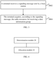
- FIG. 3 is a flowchart of a resource allocation method according to embodiments of the present application. As shown in FIG. 3 , the resource allocation method includes steps 3002 and 3004 described below.
- a terminal receives a signaling message sent by a base station.
- the signaling message is used for indicating a resource allocation mode of n data information groups used by the base station, where the resource allocation mode includes a mode one and a mode two, the mode one is that radio resources used by the n data information groups are completely overlapping and the mode two is that the radio resources used by the n data information groups are not overlapping at all, and n is an integer greater than 1.
- step 3004 the terminal acquires, according to the signaling message, radio resources for receiving the data information groups.
- the terminal receives the signaling message sent by the base station.
- the signaling message is used for indicating a resource allocation mode used by the base station.
- the resource allocation mode includes a mode one and a mode two.
- the mode one is that radio resources used by the n data information groups are completely overlapping and the mode two is that the radio resources used by the n data information groups are not overlapping at all, where n is an integer greater than 1.
- the terminal acquires, according to the signaling message, the radio resources for receiving the data information groups. This solves at least the problem in which multiple data information groups can only be transmitted by the serving cell and the cooperative cell on the same frequency-domain resources during JT transmission, severely limiting the system performance in the related art. Through this method, multiple data information groups can be transmitted on different frequency-domain resources, thereby reducing interference between different data information groups and improving the system performance.
- the method when the base station performs resource allocation by using the mode two, the method further includes that the terminal acquires, according to the signaling message, different scheduling groups corresponding to different data information groups.
- the method further includes that the terminal acquires, according to the signaling message, at least one of (i) the start position of the first scheduling group and the length of radio resources continuously occupied by the first scheduling group, (ii) an offset relationship between different scheduling groups or (iii) the index of the offset relationship between different scheduling groups.
- the offset relationship between different scheduling groups and the start position of the first scheduling group and the length of the radio resources continuously occupied by the first scheduling group are jointly coded in the signaling message; or the offset relationship between different scheduling groups and the start position of the first scheduling group and the length of the radio resources continuously occupied by the first scheduling group are indicated in a cascading manner by using multiple resource indicator values in the signaling message; or the offset relationships between different scheduling groups are jointly coded in the signaling message. Joint coding can save bit overheads.
- Embodiments of the present application further provide a resource allocation apparatus.
- the apparatus is used for implementing the above-described embodiments and optional implementations. What has been described will not be repeated.
- the term "module” is software, hardware or a combination thereof capable of implementing preset functions.
- the apparatuses in the embodiments described below are implemented by software, but implementation by hardware or by a combination of software and hardware is also possible and conceived.
- Embodiments of the present application further provide a resource allocation apparatus applied to a base station.
- the apparatus is used for implementing the above-described resource allocation.
- FIG. 4 is a structural block diagram of a resource allocation apparatus according to embodiments of the present application.
- the apparatus includes a determination module 20, which is configured to determine a resource allocation mode used by n data information groups; and an allocation module 22, which is configured to perform resource allocation by using the determined resource allocation mode.
- the resource allocation mode includes a mode one and a mode two.
- the mode one is that radio resources used by the n data information groups are completely overlapped and the mode two is that the radio resources used by the n data information groups are completely non-overlapped, where n is an integer greater than 1.
- a base station determines a resource allocation mode used by n data information groups.
- Two resource allocation modes are provided. One mode is that radio resources used by the multiple data information groups are completely overlapped and the other mode is that the radio resources used by the multiple data information groups are completely non-overlapped.
- the base station performs resource allocation by using the determined resource allocation mode.
- FIG. 5 is a structural block diagram of a resource allocation apparatus according to embodiments of the present application.
- the apparatus further includes a sending module 24, which is configured to send a signaling message to a terminal.
- the signaling message is used for indicating the resource allocation mode used by the base station and the signaling message includes at least one of radio resource control (RRC) signaling or downlink control information (DCI) signaling.
- RRC radio resource control
- DCI downlink control information
- the base station when the base station performs resource allocation by using the mode two, that is, when the radio resources used by the n data information groups are completely non-overlapped, different data information groups have different scheduling groups and an offset relationship exists between different scheduling groups.
- the signaling message is further used for indicating at least one of (i) the start position of a first scheduling group and the length of radio resources continuously occupied by the first scheduling group, (ii) the offset relationship between different scheduling groups or (iii) the index of the offset relationship between different scheduling groups.
- the scheduling groups are in one-to-one correspondence with the data information groups and the scheduling groups are used for indicating radio resources actually scheduled for use by the data information groups.
- the offset relationship exists between the (m + 1)th scheduling group and one or more of the first scheduling group to the mth scheduling group, where 1 ⁇ m ⁇ n - 1.
- the offset relationship include the cases described below.
- a first offset value exists between the start position of radio resources continuously occupied by the (m + 1)th scheduling group and the end position of radio resources continuously occupied by one or more of the first scheduling group to the mth scheduling group.
- a second offset value exists between the end position of the radio resources continuously occupied by the (m + 1)th scheduling group and the start position of the radio resources continuously occupied by one or more of the first scheduling group to the mth scheduling group.
- a third offset value exists between the end position of radio resources continuously occupied by the (m + 1)th scheduling group and the end position of radio resources continuously occupied by one or more of the first scheduling group to the mth scheduling group.
- a fourth offset value exists between the start position of the radio resources continuously occupied by the (m + 1)th scheduling group and the start position of the radio resources continuously occupied by one or more of the first scheduling group to the mth scheduling group.
- the first offset value, the second offset value, the third offset value and the fourth offset value are determined according to radio resources actually used by each of the n data information groups and is indicated by the signaling message sent by the base station to the terminal.
- the offset values is indicated or jointly indicated by some bits of the resource allocation field in DCI.
- the start position of the (m + 1)th scheduling group has an offset relationship with the start positions of multiple scheduling groups or has an offset relationship with the start position of the mth scheduling group. This is not limited in embodiments of the present application.
- a fifth offset value exists between the end position of the (m + 1)th scheduling group and the start position of the (m + 1)th scheduling group; or a sixth offset value exists between the start position of the (m + 1)th scheduling group and the end position of the (m + 1)th scheduling group.
- the fifth offset value and the sixth offset value are determined according to radio resources actually used by the data information group corresponding to the (m + 1)th scheduling group. That is, the end position of continuously occupied radio resources in radio resource allocation in the (m + 1)th scheduling group is related to the start position of radio resource allocation in the (m + 1)th scheduling group and the number of radio resources remaining after the first scheduling group to the mth scheduling group are allocated.
- the length of continuously occupied radio resources in radio resource allocation in the (m + 1)th scheduling group is indicated or jointly indicated by some bits of the resource allocation field in DCI.
- the start position of continuously occupied radio resources in radio resource allocation in the (m + 1)th scheduling group is related to the end position of radio resource allocation in the (m + 1)th scheduling group and the number of radio resources remaining after the first scheduling group to the mth scheduling group are allocated.
- the length of continuously occupied radio resources in radio resource allocation in the (m + 1)th scheduling group is indicated or jointly indicated by some bits of the resource allocation field in DCI.
- the signaling message is further used for indicating the positive value and the negative value of the offset relationship.
- the positive value and the negative value of the offset relationship use joint coding or separate coding in the signaling message.
- the offset relationship between different scheduling groups use joint coding or separate coding in the signaling message.
- the offset relationship between different scheduling groups and the start position of the first scheduling group and the length of the radio resources continuously occupied by the first scheduling group use joint coding in the signaling message.
- the joint coding of the positive value and the negative value of the offset relationship occupies one bit, thus saving bit overheads.
- the base station sends the signaling message to the terminal in one of the following sending manners: one base station sends one signaling message to the terminal; multiple base stations send multiple signaling messages to the terminal; or one base station sends multilevel signaling messages to the terminal.
- different resource allocation modes are in correspondence with the sending manners of the signaling message.
- the mode one implicitly indicates that the sending manner of the signaling message is that "one base station sends one signaling message to the terminal" and the mode two implicitly indicates that the sending manner of the signaling message is that "multiple base stations send multiple signaling messages to the terminal"; or the mode one implicitly indicates that "multiple base stations send multiple signaling messages to the terminal".
- the correspondence manner is not limited in embodiments of the present application.
- the radio resources include at least frequency-domain resources.
- the frequency-domain resources include at least one of subbands, resource blocks or resource block groups.
- the base station determines that the resource allocation mode is the mode one.
- demodulation reference signal (DMRS) ports corresponding to the n data information groups are bound to the same data information group; or the DMRS ports corresponding to the n data information groups are bound to different data information groups.
- DMRS demodulation reference signal
- Embodiments of the present application further provide a resource allocation apparatus applied to a terminal.
- the apparatus is used for implementing the above-described resource allocation.
- FIG. 6 is a structural block diagram of a resource allocation apparatus according to embodiments of the present application.
- the apparatus includes a receiving module 60, which is configured to receive a signaling message sent by a base station; and an acquisition module 62, which is configured to acquire, according to the signaling message, the radio resources for receiving the data information groups.
- the resource allocation mode includes a mode one and a mode two.
- the mode one is that radio resources used by the n data information groups are completely overlapped and the mode two is that the radio resources used by the n data information groups are completely non-overlapped, where n is an integer greater than 1.
- a terminal receives a signaling message sent by a base station and the terminal acquires, according to the signaling message, the radio resources for receiving the data information groups.
- the resource allocation mode includes a mode one and a mode two.
- the mode one is that radio resources used by the n data information groups are completely overlapped and the mode two is that the radio resources used by the n data information groups are completely non-overlapped, where n is an integer greater than 1.
- the acquisition module 62 is further configured to acquire, according to the signaling message, different scheduling groups corresponding to different data information groups.
- the acquisition module 62 is further configured to acquire, according to the signaling message, at least one of (i) the start position of the first scheduling group and the length of radio resources continuously occupied by the first scheduling group, (ii) an offset relationship between different scheduling groups or (iii) the index of the offset relationship between different scheduling groups.
- the offset relationship between different scheduling groups and the start position of the first scheduling group and the length of the radio resources continuously occupied by the first scheduling group use joint coding in the signaling message; or the offset relationship between different scheduling groups and the start position of the first scheduling group and the length of the radio resources continuously occupied by the first scheduling group are indicated by multiple cascaded resource indicator values in the signaling message; or the offset relationship between different scheduling groups uses joint coding in the signaling message.
- demodulation reference signal (DMRS) ports corresponding to the n data information groups are bound to the same data information group; or the DMRS ports corresponding to the n data information groups are bound to different data information groups.
- DMRS demodulation reference signal
- Embodiments of the present application further provide a storage medium.
- the storage medium includes a stored program.
- the program is configured such that the above-described resource allocation methods and embodiments are performed.
- Embodiments of the present application further provide a resource allocation apparatus.
- the apparatus includes a processor and a memory, which is configured to store instructions executable by the processor.
- the processor is configured to perform the following operations according to the instructions stored in the memory: determining a resource allocation mode used by n data information groups and performing resource allocation by using the determined resource allocation mode.
- the resource allocation mode includes a mode one and a mode two. The mode one is that radio resources used by the n data information groups are completely overlapped and the mode two is that the radio resources used by the n data information groups are completely non-overlapped, where n is an integer greater than 1.
- the processor is further configured to send a signaling message to a terminal.
- the signaling message is used for indicating the resource allocation mode used by the processor and the signaling message includes at least one of radio resource control (RRC) signaling or downlink control information (DCI) signaling.
- RRC radio resource control
- DCI downlink control information
- different data information groups have different scheduling groups and an offset relationship exists between different scheduling groups
- the signaling message is further used for indicating at least one of (i) the start position of the first scheduling group and the length of radio resources continuously occupied by the first scheduling group, (ii) the offset relationship between different scheduling groups or (iii) the index of the offset relationship between different scheduling groups.
- the offset relationship between different scheduling groups and the start position of the first scheduling group and the length of the radio resources continuously occupied by the first scheduling group use joint coding in the signaling message; or the offset relationship between different scheduling groups uses joint coding in the signaling message.
- the processor here further perform any steps in the above-described resource allocation methods and the examples of the resource allocation methods, and serve as a carrier for each function module in the above-described resource allocation apparatuses.
- Embodiments of the present application provide a resource allocation method. As shown in FIG. 7 , the method includes steps 201 to 203 described below.
- a base station 1 configures a DCI message.
- the base station 1 determines whether to use a completely overlapping resource allocation mode or a completely non-overlapping resource allocation mode according to measurement information fed back by a terminal in combination with the service condition/terminal capability.
- the base station 1 interacts with a base station 2.
- the base station 2 learns about radio resources occupied by the scheduling group corresponding to the codeword sent by the base station 2.
- step 202 the base station 1 sends a DCI message (equivalent to DCI signaling) and data corresponding to codeword 1 and the base station 2 sends data corresponding to codeword 2.
- step 203 the terminal acquires the DCI message, determines whether to use a completely overlapping mode or a completely non-overlapping mode according to indication information in the DCI message, and receives data according to the resource allocation field in the DCI message.
- the DCI message supports switching between a manner that n codewords use the same resource allocation mode and a manner that n codewords use different resource allocation modes.
- the same resource allocation mode means that radio resources used by the n codewords are completely overlapped.
- Different resource allocation modes mean that radio resources used by the n codewords are completely non-overlapped, where n is greater than 1. In an embodiment, n is equal to 2.
- FIG. 8 is a schematic diagram of a completely overlapping allocation mode and a completely non-overlapping allocation mode according to embodiments of the present application. As shown in FIG. 8 , embodiments of the present application provide two resource allocation modes: a completely overlapping mode and a completely non-overlapping mode.
- switching indication signaling indicates that the same resource allocation mode or different resource allocation modes are used between the n codewords.
- 1-bit signaling is used, 0 indicates completely overlapping and 1 indicates completely non-overlapping.
- switching indication information is sent through at least one of an RRC message or a DCI message.
- the switching indication information is sent through the DCI message; as shown in FIG. 9 , the switching indication information is sent through the RRC message.
- resource-allocation-related signaling in the DCI message is used for indicating the actual resource allocation of the n codewords, where n is greater than 1.
- the resource-allocation-related signaling in the DCI message uses the LTE resource allocation method and definition.
- the LTE resource allocation method and definition refers to resource allocation mode 0/1/2.
- the different codewords have different scheduling groups, and an offset relationship exists between different scheduling groups.
- the first scheduling group is indicated in the form of the start position and continuously occupied radio resources.
- the scheduling groups are in one-to-one correspondence with codewords and indicate radio resources actually scheduled for use on the codewords.
- the first scheduling group refers to the scheduling group corresponding to codeword 1.
- continuously occupied radio resources and the start position of the first scheduling group are indicated by ceil log 2 R Num * R Num + 1 / 2 bits in the resource-allocation-related signaling in the DCI message.
- R Num denotes the number of radio resources and ceil denotes rounding up to an integer.
- the radio resources include frequency-domain resources.
- the frequency-domain resources include at least one of subbands, resource blocks or resource block groups.
- FIG. 10 is a schematic diagram of DCI signaling according to embodiments of the present application. As shown in FIG. 10 , the first ceil log 2 R Num * R Num + 1 / 2 bits in the resource-allocation-related signaling in the DCI message are used for indicating the resource allocation of codeword 1.
- the offset relationship exists between the (m + 1)th scheduling group and at least one of the first scheduling group to the mth scheduling group.
- the case where the (m + 1)th scheduling group (a1) has the offset relationship with at least one scheduling group (a2) of the first scheduling group to the mth scheduling group refers to the case where a first offset value exists between the start position (b1) of radio resources continuously occupied by the (m + 1)th scheduling group and the end position (b2) of radio resources continuously occupied by at least one of the first scheduling group to the mth scheduling group.
- the first offset value is indicated or jointly indicated by part of bits in resource-allocation-related signaling in the DCI message.
- the case where the offset relationship exists between the (m + 1)th scheduling group (a1) and at least one (a2) of the first scheduling group to the mth scheduling group refers to the case where a first offset value exists between the end position (c1) of radio resources continuously occupied by the (m + 1)th scheduling group and the start position (c2) of radio resources continuously occupied by at least one of the first scheduling group to the mth scheduling group.
- the first offset value is indicated or jointly indicated by part of bits in resource-allocation-related signaling in the DCI message.
- the case where the (m + 1)th scheduling group (a1) has the offset relationship with at least one scheduling group (a2) of the first scheduling group to the mth scheduling group refers to the case where a second offset value exists between the end position (c1) of radio resources continuously occupied by the (m + 1)th scheduling group and the end position (b2) of radio resources continuously occupied by at least one of the first scheduling group to the mth scheduling group.
- the second offset value is indicated or jointly indicated by part of bits of resource-allocation-related signaling in the DCI message.
- the case where the (m + 1)th scheduling group (a1) has the offset relationship with at least one scheduling group (a2) of the first scheduling group to the mth scheduling group refers to the case where a second offset value exists between the start position (b1) of radio resources continuously occupied by the (m + 1)th scheduling group and the start position (c2) of radio resources continuously occupied by at least one of the first scheduling group to the mth scheduling group.
- the second offset value is indicated or jointly indicated by part of bits of resource-allocation-related signaling in the DCI message.
- the end position (c1) of continuously occupied radio resources of the (m + 1)th scheduling group in radio resource allocation is related to the start position (b1) of radio resource allocation in the (m + 1)th scheduling group and the number of radio resources remaining after the first scheduling group to the mth scheduling group are allocated.
- the length of continuously occupied radio resources in radio resource allocation in the (m + 1)th scheduling group is indicated or jointly indicated by part of bits of resource-allocation-related signaling in the DCI message.
- the start position (b1) of continuously occupied radio resources in radio resource allocation in the (m + 1)th scheduling group is related to the end position (c1) of radio resource allocation in the (m + 1)th scheduling group and the number of radio resources remaining after the first scheduling group to the mth scheduling group are allocated.
- the length of continuously occupied radio resources in radio resource allocation in the (m + 1)th scheduling group is indicated or jointly indicated by part of bits of resource-allocation-related signaling in the DCI message.
- FIG. 11 is a schematic diagram of resource allocation according to embodiments of the present application.
- the offset relationship that is, a first offset value, exists between the start position of the second scheduling group and the end position of radio resource allocation in the first scheduling group.
- the system bandwidth is 25 frequency-domain resources, which are numbered from 0, and codeword 1 continuously occupies the second frequency-domain resource to the 11th frequency-domain resource, then the number of remaining continuous frequency-domain resources is 13, and then the first offset value needs to be indicated by ceil log 2 13 equal to four bits at most and the first offset value is a positive value.
- the second bit field in the resource allocation signaling in the DCI message is used for indication.
- one bit is used for indication, and 0 indicates that the first offset value is a positive value and 1 indicates that the first offset value is a negative value.
- the offset relationship that is, a second offset value, exists between the end position of the second scheduling group and the end position of radio resource allocation in the first scheduling group.
- the system bandwidth is 25 frequency-domain resources, which are numbered from 0, and codeword 1 continuously occupies the second frequency-domain resource to the 11th frequency-domain resource, then the number of remaining continuous frequency-domain resources is 13, and then the second offset value needs to be indicated by ceil log 2 13 equal to four bits at most and the second offset value is a positive value.
- the fourth bit field in the resource allocation signaling in the DCI message is used for indication.
- one bit is used for indication, and 0 indicates that the first offset value is a positive value and 1 indicates that the first offset value is a negative value.
- FIG. 12 is a schematic diagram of resource allocation according to embodiments of the present application.
- the offset relationship that is, a first offset value, exists between the end position of the second scheduling group and the start position of radio resource allocation in the first scheduling group.
- the system bandwidth is 25 frequency-domain resources, which are numbered from 0, and codeword 1 continuously occupies the 16th frequency-domain resource to the 24th frequency-domain resource, then the number of remaining continuous frequency-domain resources is 16, and then the first offset value needs to be indicated by ceil log 2 16 equal to four bits at most and the first offset value is a negative value.
- FIG. 13 is a schematic diagram of DCI signaling according to embodiments of the present application. As shown in FIG.
- the second bit field in the resource allocation signaling in the DCI message is used for indication.
- one bit is used for indication, and 0 indicates that the first offset value is a positive value and 1 indicates that the first offset value is a negative value.
- the offset relationship that is, a first offset value, exists between the start position of the second scheduling group and the start position of radio resource allocation in the second scheduling group.
- the system bandwidth is 25 frequency-domain resources, which are numbered from 0, and codeword 1 continuously occupies the 16th frequency-domain resource to the 24th frequency-domain resource, then the number of remaining continuous frequency-domain resources is 16, and then the fourth offset value needs to be indicated by ceil log 2 16 equal to four bits at most and the second offset value is a negative value.
- the second bit field in the resource allocation signaling in the DCI message is used for indication. The second bit field are used for indicating both the first offset value and the second offset value.
- the offset relationship that is, a first offset value, exists between the end position of the second scheduling group and the start position of radio resource allocation in the first scheduling group.
- the system bandwidth is 25 frequency-domain resources, which are numbered from 0, and codeword 1 continuously occupies the 16th frequency-domain resource to the 24th frequency-domain resource, then the number of remaining continuous frequency-domain resources is 16, and then the first offset value needs to be indicated by ceil log 2 16 equal to four bits at most and the first offset value is a negative value.
- the second bit field in the resource allocation signaling in the DCI message is used for indication.
- one bit is used for indication, and 0 indicates that the first offset value is a positive value and 1 indicates that the first offset value is a negative value.
- the length of radio resources continuously occupied by the second scheduling group is related to the end position and maximum number of radio resources continuously occupied by the second scheduling group.
- codeword 1 continuously occupies the 16th frequency-domain resource to the 24th frequency-domain resource, and it is calculated from the first offset value that the end position of the second scheduling group is the 12th frequency-domain resource, then the number of remaining continuous frequency-domain resources is 12, and then the length of radio resources continuously occupied by the second scheduling group needs to be indicated by ceil log 2 12 equal to four bits at most and the value of the length is a positive value.
- the end position of the first scheduling group is determined by the first offset value and the first offset positive and negative values.
- the length of radio resources continuously occupied by the second scheduling group determines the start position of radio resources continuously occupied by two scheduling groups.
- the first offset value is indicated by the third bit field in the resource allocation signaling in the DCI message and the second offset value is indicated by the fifth bit field in the resource allocation signaling in the DCI message.
- the first offset value is indicated by the third bit field in the resource allocation signaling in the DCI message and the second offset value is indicated by the fourth bit field in the resource allocation signaling in the DCI message.
- FIG. 14 is a schematic diagram of DCI signaling according to embodiments of the present application. As shown in FIG. 14 , the first offset value and the second offset value is indicated by using joint coding and is acquired by the UE through a look-up table.
- FIG. 15 is a schematic diagram of DCI signaling according to embodiments of the present application. As shown in FIG. 15 , the first offset value is indicated by the third bit field in the resource allocation signaling in the DCI message and the length of continuously occupied radio resources is indicated by the fourth bit field in the resource allocation signaling in the DCI message.
- the UE determines, according to switching indication signaling, whether the n codewords use the same resource allocation mode or different resource allocation modes.
- switching indication signaling In an embodiment, 1-bit signaling is used, 0 indicates completely overlapping and 1 indicates completely non-overlapping.
- the resource-allocation-related signaling in the DCI message uses the LTE resource allocation method and definition.
- the LTE resource allocation method and definition refers to resource allocation mode 0/1/2.
- the scheduling groups of different codewords are different, and an offset relationship exists between different scheduling groups.
- the first scheduling group is indicated by means of the start position and continuously occupied radio resources.
- FIG. 16 is a flowchart of a resource allocation method according to embodiments of the present application. As shown in FIG. 16 , the method includes steps 601 to 603 described below.
- a base station configures an RRC message and a DCI message.
- a base station 1 sends the DCI message and data corresponding to codeword 1 to a UE and a base station 2 sends data corresponding to codeword 2 to the UE.
- step 603 the UE acquires the DCI message, and receives data according to the resource-allocation-related signaling in the DCI message.
- the RRC message supports switching between a case where the n codewords use the same resource allocation mode and a case where the n codewords use different resource allocation modes.
- the same resource allocation mode means that radio resources used by the n data information groups are not overlapped and different resource allocation modes mean that radio resources used by the n data information groups are not non-overlapped.
- n is greater than 1. In an embodiment, n is equal to 3.
- switching indication signaling indicates that the n codewords use the same resource allocation mode or different resource allocation modes.
- 1-bit signaling is used, 0 indicates completely overlapping and 1 indicates completely non-overlapping.
- the switching indication information is sent through at least one of the RRC message or the DCI message.
- the switching indication information is sent through the RRC message.
- resource-allocation-related signaling in the DCI message is used for indicating the actual resource allocation of the n codewords. n is greater than 1.
- the resource-allocation-related signaling in the DCI message uses the LTE resource allocation method and definition.
- the LTE resource allocation method and definition refers to resource allocation mode 0/1/2.
- the scheduling groups of different codewords are different, and an offset relationship exists between different scheduling groups.
- the first scheduling group is indicated or jointly indicated by means of the start position and continuously occupied radio resources.
- the scheduling groups are in one-to-one correspondence with codewords and indicate radio resources actually scheduled for use by the codewords.
- the first scheduling group refers to the scheduling group corresponding to codeword 1.
- continuously occupied radio resources and the start position of the first scheduling group are indicated by ceil log 2 R Num * R Num + 1 / 2 bits in the resource-allocation-related signaling in the DCI message.
- R Num denotes the number of radio resources.
- the radio resources include frequency-domain resources.
- the frequency-domain resources include at least one of subbands, resource blocks or resource block groups.
- the frequency-domain resources are resource blocks (RBs).
- FIG. 17 is a schematic diagram of DCI signaling according to embodiments of the present application. As shown in FIG. 17 , the first ceil log 2 R Num * R Num + 1 / 2 bits in the resource-allocation-related signaling in the DCI message are used for indicating codeword-1 resource allocation.
- the offset relationship exists between the (m + 1)th scheduling group and at least one of the first scheduling group to the mth scheduling group.
- the offset relationship between the (m + 1)th scheduling group (a1) and at least one scheduling group (a2) of the first scheduling group to the mth scheduling group refers to a first offset value between the start position (b1) of radio resources continuously occupied by the (m + 1)th scheduling group and the end position (b2) of radio resources continuously occupied by at least one of the first scheduling group to the mth scheduling group.
- the first offset value is indicated by part of bits of resource-allocation-related signaling in the DCI message.
- the offset relationship between the (m + 1)th scheduling group (a1) and at least one scheduling group (a2) of the first scheduling group to the mth scheduling group refers to a first offset value between the end position (c1) of radio resources continuously occupied by the (m + 1)th scheduling group and the start position (c2) of radio resources continuously occupied by at least one scheduling group of the first scheduling group to the mth scheduling group.
- the first offset value is indicated by part of bits of resource-allocation-related signaling in the DCI message.
- the offset relationship between the (m + 1)th scheduling group (a1) and at least one scheduling group (a2) of the first scheduling group to the mth scheduling group refers to a second offset value between the end position (c1) of radio resources continuously occupied by the (m + 1)th scheduling group and the end position (b2) of radio resources continuously occupied by at least one scheduling group of the first scheduling group to the mth scheduling group.
- the second offset value is indicated or jointly indicated by part of bits of resource-allocation-related signaling in the DCI message.
- the offset relationship between the (m + 1)th scheduling group (a1) and at least one scheduling group (a2) of the first scheduling group to the mth scheduling group refers to a second offset value between the start position (b1) of radio resources continuously occupied by the (m + 1)th scheduling group and the start position (c2) of radio resources continuously occupied by at least one scheduling group of the first scheduling group to the mth scheduling group.
- the second offset value is indicated or jointly indicated by part of bits of resource-allocation-related signaling in the DCI message.
- the end position (c1) of continuously occupied radio resources of the radio resource allocation of the (m + 1)th scheduling group is related to the start position (b1) of radio resource allocation of the (m + 1)th scheduling group and the number of radio resources remaining after the first scheduling group to the mth scheduling group are allocated.
- the length of continuously occupied radio resources of radio resource allocation of the (m + 1)th scheduling group is indicated or jointly indicated by part of bits of resource-allocation-related signaling in the DCI message.
- the start position (b1) of continuously occupied radio resources of radio resource allocation of the (m + 1)th scheduling group is related to the end position (c1) of radio resource allocation in the (m + 1)th scheduling group and the number of radio resources remaining after the first scheduling group to the mth scheduling group are allocated.
- the length of continuously occupied radio resources in radio resource allocation in the (m + 1)th scheduling group is indicated or jointly indicated by part of bits of resource-allocation-related signaling in the DCI message.
- FIG. 18 is a schematic diagram of resource allocation according to embodiments of the present application.
- an offset relationship that is, a first offset value 1 exists between the start position of the second scheduling group and the end position of radio resource allocation of the first scheduling group.
- the system bandwidth is 50 frequency-domain resources, which are numbered from 0, and codeword 1 continuously occupies the second frequency-domain resource to the 15th frequency-domain resource, then the number of remaining continuous frequency-domain resources is 34, and then first offset value 1 needs to be indicated by ceil log 2 34 equal to six bits at most and first offset value 1 is a positive value.
- the second bit field in the resource allocation signaling in the DCI message is used for indication.
- one bit is used for indication, and 0 indicates that first offset value 1 is a positive value and 1 indicates that first offset value 1 is a negative value.
- an offset relationship that is, a first offset value 2 exists between the start position of the third scheduling group and the end position of radio resource allocation in the second scheduling group.
- the system bandwidth is 50 frequency-domain resources, which are numbered from 0, and codeword 2 continuously occupies the 20th frequency-domain resource to the 41th frequency-domain resource, then the number of remaining continuous frequency-domain resources is eight, and then the indication of the first offset value 2 needs ceil log 2 8 equal to four bits at most and the first offset value 2 is a positive value.
- the sixth bit field in the resource allocation signaling in the DCI message is used for indication.
- one bit is used for indication, and 0 indicates that first offset value 2 is a positive value and 1 indicates that first offset value 2 is a negative value.
- an offset relationship that is, a second offset value 1 exists between the end position of the second scheduling group and the end position of radio resource allocation in the first scheduling group.
- the system bandwidth is 50 frequency-domain resources, which are numbered from 0, and codeword 1 continuously occupies the second frequency-domain resource to the 15th frequency-domain resource, then the number of remaining continuous frequency-domain resources is 34, and then the indication of the second offset value 1 needs ceil log 2 34 equal to six bits at most and the second offset value 1 is a positive value.
- the fourth bit field in the resource allocation signaling in the DCI message is used for indication.
- one bit is used for indication, and 0 indicates that first offset value 1 is a positive value and 1 indicates that first offset value 1 is a negative value.
- an offset relationship that is, a second offset value 2 exists between the end position of the third scheduling group and the end position of radio resource allocation in the second scheduling group.
- the system bandwidth is 50 frequency-domain resources, which are numbered from 0, and codeword 1 continuously occupies the 20th frequency-domain resource to the 41th frequency-domain resource, then the number of remaining continuous frequency-domain resources is eight, and then the indication of the second offset value 2 needs ceil log 2 8 equal to four bits at most and the second offset value 2 is a positive value.
- the eighth bit field in the resource allocation signaling in the DCI message is used for indication.
- one bit is used for indication, and 0 indicates that first offset value 2 is a positive value and 1 indicates that first offset value 2 is a negative value.
- FIG. 19 is a schematic diagram of resource allocation according to embodiments of the present application.
- an offset relationship that is, a first offset value 1 exists between the end position of the second scheduling group and the start position of radio resource allocation of the first scheduling group.
- the system bandwidth is 50 frequency-domain resources, which are numbered from 0, and codeword 1 continuously occupies the 20th frequency-domain resource to the 41th frequency-domain resource, then the number of remaining continuous frequency-domain resources on the left side is 20, and then the indication of the first offset value 1 needs ceil log 2 20 equal to five bits at most and first offset value 1 is a negative value.
- the second bit field in the resource allocation signaling in the DCI message is used for indication.
- one bit is used for indication, and 0 indicates that the first offset value 1 is a positive value and 1 indicates that first offset value 1 is a negative value.
- an offset relationship that is, a first offset value 2 exists between the start position of the third scheduling group and the end position of radio resource allocation of the first scheduling group.
- the system bandwidth is 50 frequency-domain resources, which are numbered from 0, and codeword 1 continuously occupies the 20th frequency-domain resource to the 41th frequency-domain resource, then the number of remaining continuous frequency-domain resources on the right side is 8, and then the indication of the first offset value 2 needs ceil log 2 8 equal to four bits at most and the first offset value 2 is a positive value. As shown in FIG.
- the fifth bit field in the resource allocation signaling in the DCI message is used for indication.
- one bit is used for indication, and 0 indicates that the first offset value 2 is a positive value and 1 indicates that the first offset value 2 is a negative value.
- an offset relationship that is, a second offset value 1 exists between the start position of the second scheduling group and the start position of radio resource allocation of the first scheduling group.
- the system bandwidth is 50 frequency-domain resources, numbering starts from 0, and codeword 1 continuously occupies the 20th frequency-domain resource to the 41th frequency-domain resource, then the number of remaining continuous frequency-domain resources on the left side is 20, and then the indication of the first offset value 1 needs ceil log 2 20 equal to five bits at most and the second offset value 1 is a negative value.
- the second bit field in the resource allocation signaling in the DCI message is used for indication. The second bit field are used for indicating both the first offset value 1 and the second offset value 1.
- an offset relationship that is, a second offset value 2 exists between the end position of the third scheduling group and the end position of radio resource allocation of the first scheduling group.
- the system bandwidth is 50 frequency-domain resources, which are numbered from 0, and codeword 1 continuously occupies the 20th frequency-domain resource to the 41th frequency-domain resource, then the number of remaining continuous frequency-domain resources on the right side is eight, and then the indication of the second offset value 2 needs at most ceil log 2 8 equal to four bits and the second offset value 2 is a positive value.
- the fifth bit field in the resource allocation signaling in the DCI message is used for indication. The fifth bit field is used for indicating both the first offset value 2 and the second offset value 2.
- the UE determines, according to switching indication signaling, whether the n codewords use the same resource allocation mode or different resource allocation modes.
- switching indication signaling In an embodiment, 1-bit signaling is used, 0 indicates completely overlapping and 1 indicates completely non-overlapping.
- the resource-allocation-related signaling in the DCI message uses the LTE resource allocation method and definition.
- the LTE resource allocation method and definition refers to resource allocation mode 0/1/2.
- the scheduling groups of different codewords are different, and an offset relationship exists between different scheduling groups.
- the first scheduling group is indicated or jointly indicated by means of the start position and the continuously occupied radio resources.
- FIG. 21 is a flowchart of a resource allocation method according to embodiments of the present application. As shown in FIG. 21 , the method includes steps 401 to 403 described below.
- a base station 1 configures a DCI message 1 and a base station 2 configures a DCI message 2.
- step 402 the base station 1 sends the DCI message and data corresponding to codeword 1 to a UE and the base station 2 sends DCI message 2 and data corresponding to codeword 2 to the UE.
- step 403 the UE acquires the DCI message 1 and DCI message 2, and receives data according to the resource-allocation-related signaling in DCI message 1 and DCI message 2.
- the DCI message 1 indicates the resource allocation method of codeword 1 and DCI message 2 indicates the resource allocation method of codeword 2.
- the DCI message supports switching between n codewords using the same resource allocation mode and n codewords using different resource allocation modes.
- Using the same resource allocation mode means that radio resources used by the n codewords are completely overlapped.
- Using different resource allocation modes means that radio resources used by the n codewords are completely non-overlapped, where n is greater than 1. In an embodiment, completely overlapping and completely non-overlapping are as shown in FIG. 8 .
- switching indication signaling indicates that the n codewords use the same resource allocation mode or different resource allocation modes.
- 1-bit signaling is used for indication, 0 indicates completely overlapping and 1 indicates completely non-overlapping.
- the switching indication information is sent through at least one of an RRC message or a DCI message. In an embodiment, as shown in FIG. 5 , the switching indication information is sent through the DCI message. In an embodiment, as shown in FIG. 9 , the switching indication information is sent through the RRC message.
- resource-allocation-related signaling in the DCI message is used for indicating the actual resource allocation of the n codewords. n is greater than 1.
- the resource-allocation-related signaling in the DCI message uses the LTE resource allocation method and definition.
- the LTE resource allocation method and definition refers to resource allocation mode 0/1/2.
- the scheduling groups of different codewords are different, and an offset relationship exists between different scheduling groups.
- the first scheduling group is indicated or jointly indicated by means of the start position and continuously occupied radio resources.
- the scheduling groups are in one-to-one correspondence with codewords and indicate radio resources actually scheduled for the codewords.
- the first scheduling group refers to the scheduling group corresponding to codeword 1.
- the continuously occupied radio resources and the start position of the first scheduling group are indicated by ceil log 2 R Num * R Num + 1 / 2 bits in the resource-allocation-related signaling in the DCI message.
- R Num denotes the number of radio resources.
- the radio resources include frequency-domain resources.
- the frequency-domain resources include at least one of subbands, resource blocks or resource block groups.
- the first ceil log 2 R Num * R Num + 1 / 2 bits in the resource-allocation-related signaling in the DCI message are used for indicating the resource allocation of codeword-1.
- the offset relationship exists between the (m + 1)th scheduling group and at least one of the first scheduling group to the mth scheduling group.
- the offset relationship between the (m + 1)th scheduling group (a1) and at least one scheduling group (a2) of the first scheduling group to the mth scheduling group refers to a first offset value between the start position (b1) of radio resources continuously occupied the radio resource allocation of the (m + 1)th scheduling group and the end position (b2) of the radio resources allocation of the at least one scheduling group of the first scheduling group to the mth scheduling group.
- the first offset value is indicated or jointly indicated by part of bits of resource-allocation-related signaling in the DCI message.
- the offset relationship between the (m + 1)th scheduling group (a1) and at least one scheduling group (a2) of the first scheduling group to the mth scheduling group refers to a first offset value between the end position (c1) of radio resources continuously occupied the radio resource allocation of the (m + 1)th scheduling group and the start position (c2) of the radio resources allocation of the at least one scheduling group of the first scheduling group to the mth scheduling group.
- the first offset value is indicated or jointly indicated by part of bits of resource-allocation-related signaling in the DCI message.
- the offset relationship between the (m + 1)th scheduling group (a1) and at least one scheduling group (a2) of the first scheduling group to the mth scheduling group refers to a second offset value between the end position (c1) of radio resources continuously occupied by the radio resource allocation of the (m + 1)th scheduling group and the end position (b2) of the radio resource allocation of the at least one scheduling group of the first scheduling group to the mth scheduling group.
- the second offset value is indicated or jointly indicated by part of bits of resource-allocation-related signaling in the DCI message.
- the offset relationship between the (m + 1)th scheduling group (a1) and at least one scheduling group (a2) of the first scheduling group to the mth scheduling group refers to a second offset value exists between the start position (b1) of radio resources continuously occupied by the radio resource allocation of the (m + 1)th scheduling group and the start position (c2) of the radio resource allocation of the at least one of the first scheduling group to the mth scheduling group.
- the second offset value is indicated or jointly indicated by part of bits of resource-allocation-related signaling in the DCI message.
- the end position (c1) of radio resources continuously occupied the radio resource allocation of the (m + 1)th scheduling group is related to the start position (b1) of the radio resource allocation of the (m + 1)th scheduling group and the number of radio resources remaining after the first scheduling group to the mth scheduling group are allocated.
- the length of the radio resources continuously occupied by the radio resource allocation in the (m + 1)th scheduling group is indicated or jointly indicated by part of bits of resource-allocation-related signaling in the DCI message.
- the start position (b1) of the radio resources continuously occupied by the radio resource allocation of the (m + 1)th scheduling group is related to the end position (c1) of radio resource allocation of the (m + 1)th scheduling group and the number of radio resources remaining after the first scheduling group to the mth scheduling group are allocated.
- the length of radio resources continuously occupied by the radio resource allocation of the (m + 1)th scheduling group is indicated or jointly indicated by part of bits of resource-allocation-related signaling in the DCI message.
- the first offset value is indicated by the third bit field in the resource allocation signaling in the DCI message and the second offset value is indicated by the fifth bit field in the resource allocation signaling in the DCI message.
- the first offset value is indicated by the third bit field in the resource allocation signaling in the DCI message and the second offset value is indicated by the fourth bit field in the resource allocation signaling in the DCI message.
- the first offset value and the second offset value is indicated by using joint coding and is acquired by the UE through a look-up table.
- the first offset value and the second offset value are acquired through a look-up table by using index information.
- two bits are used for indicating the index information of the first offset value. See Table 1. Table 1 Index RB Num 00 0 01 2 10 4 11 6
- the first offset value is indicated by the third bit field in the resource allocation signaling in the DCI message and the length of continuously occupied radio resources is indicated by the fourth bit field in the resource allocation signaling in the DCI message.
- the UE receives data corresponding to codeword 1 according to the DCI message 1 and receives data corresponding to codeword 2 according to the DCI message 2.
- the UE determines, according to switching indication signaling, whether the n codewords use the same resource allocation mode or different resource allocation modes.
- switching indication signaling In an embodiment, 1-bit signaling is used for the indication, 0 indicates completely overlapping and 1 indicates completely non-overlapping.
- the resource-allocation-related signaling in the DCI message uses the LTE resource allocation method and definition.
- the LTE resource allocation method and definition refers to resource allocation mode 0/1/2.
- the scheduling groups of different codewords are different, and an offset relationship exists between different scheduling groups.
- the first scheduling group is indicated or jointly indicated by means of the start position and continuously occupied radio resources.
- FIG. 22 is a method for indicating mapping from codeword to a transmission layer according to embodiments of the present application. As shown in FIG. 22 , the method includes steps 501 to 503 described below.
- a base station configures a DCI message.
- a base station 1 sends the DCI message and data corresponding to codeword 1 and a base station 2 sends data corresponding to codeword 2.
- a terminal acquires the DCI message and determines DMRS port information and receives data.
- the codeword-to-layer mapping under spatial multiplexing is as shown in Table 2.
- the first codeword is transmitted in one layer and the second codeword is transmitted in two layers according to Table 1.
- DCI is used for notifying the UE of the relationship between codewords/antenna ports/scrambling IDs/the number of layers, as shown in Table 3.
- DMRS port information corresponding to different codewords are obtained through Table 2 and Table 3.
- the DCI message carries information indicating DMRS ports.
- codeword 1 and codeword 2 use consistent DMRS ports.
- codeword 1 uses DMRS ports 7 and 8 and codeword 2 also uses DMRS ports 7 and 8.
- codeword 1 uses DMRS ports 7 and 8 and codeword 2 uses DMRS ports 11 and 13.
- Table 4 DMRS port information of different codewords is indicated by added signaling.
- This embodiment provides a resource allocation method. As shown in FIG. 7 , the method includes steps 201 to 203 described below.
- a base station 1 configures a DCI message.
- the base station 1 determines whether to use a completely overlapping resource allocation mode or a completely non-overlapping resource allocation mode according to measurement information fed back by a terminal in combination with the service condition/terminal capability.
- the base station 1 interacts with a base station 2.
- the base station 2 learns about radio resources occupied by the scheduling group corresponding to the codeword sent by the base station 2.
- step 202 the base station 1 sends a DCI message (equivalent to DCI signaling) and data corresponding to codeword 1 and the base station 2 sends data corresponding to codeword 2.
- step 203 the terminal acquires the DCI message, determines whether to use a completely overlapping mode or a completely non-overlapping mode according to indication information in the DCI message, and receives data according to resource-allocation-related signaling in the DCI message.
- the DCI message supports switching between a condition n codewords use the same resource allocation mode or a condition the n codewords use different resource allocation modes.
- Using the same resource allocation mode means that radio resources used by the n codewords are completely overlapped.
- Using different resource allocation modes means that radio resources used by the n codewords are not overlapped at all.
- n is greater than 1. In an embodiment, n is equal to 2.
- FIG. 8 is a schematic diagram of a completely overlapping allocation mode and a completely non-overlapping allocation mode according to embodiments of the present application. As shown in FIG. 8 , embodiments of the present application provide two resource allocation modes: a completely overlapping mode and a completely non-overlapping mode.
- switching indication signaling indicates that the n codewords use the same resource allocation mode or different resource allocation modes.
- 1-bit signaling is used for indication, 0 indicates completely overlapping and 1 indicates completely non-overlapping.
- the switching indication information is sent through at least one of an RRC message or a DCI message. In an embodiment, as shown in FIG. 7 , the switching indication information is sent through the DCI message; as shown in FIG. 9 , the switching indication information is sent through the RRC message.
- resource-allocation-related signaling in the DCI message is used for indicating the actual resource allocation of the n codewords. n is greater than 1.
- the resource-allocation-related signaling in the DCI message uses the LTE resource allocation method and definition.
- the LTE resource allocation method and definition refers to resource allocation mode 0/1/2.
- the scheduling groups of different codewords are different, and an offset relationship exists between different scheduling groups.
- the scheduling groups are in one-to-one correspondence with codewords and indicate radio resources actually scheduled on the codewords.
- the first scheduling group refers to the scheduling group corresponding to codeword 1.
- the radio resources include frequency-domain resources.
- the frequency-domain resources include at least one of subbands, resource blocks or resource block groups.
- the offset relationship exists between the (m + 1)th scheduling group and at least one of the first scheduling group to the mth scheduling group.
- the offset relationship between the (m + 1)th scheduling group (a1) and at least one scheduling group (a2) among the first scheduling group to the mth scheduling group refers to a first offset value between the start position (b1) of radio resources continuously occupied by the radio resource allocation of the (m + 1)th scheduling group and the end position (b2) of the radio resource allocation of the at least one scheduling group of the first scheduling group to the mth scheduling group.
- the first offset value is indicated or jointly indicated by part of bits of resource-allocation-related signaling in the DCI message.
- the offset relationship between the (m + 1)th scheduling group (a1) and at least one scheduling group (a2) of the first scheduling group to the mth scheduling group refers to a first offset value between the end position (c1) of radio resources continuously occupied by the radio resource allocation of the (m + 1)th scheduling group and the start position (c2) of the radio resource allocation of the at least one scheduling group of the first scheduling group to the mth scheduling group.
- the first offset value is indicated or jointly indicated by part of bits of the resource-allocation-related signaling in the DCI message.
- the offset relationship between the (m + 1)th scheduling group (a1) and at least one scheduling group (a2) of the first scheduling group to the mth scheduling group refers to a second offset value between the end position (c1) of radio resources continuously occupied by the radio resource allocation of the (m + 1)th scheduling group and the end position (b2) of the radio resource allocation of the at least one scheduling group of the first scheduling group to the mth scheduling group.
- the second offset value is indicated or jointly indicated by part of bits of the resource-allocation-related signaling in the DCI message.
- the offset relationship between the (m + 1)th scheduling group (a1) and at least one scheduling group (a2) of the first scheduling group to the mth scheduling group refers to a second offset value between the start position (b1) of radio resources continuously occupied by the radio resource allocation of the (m + 1)th scheduling group and the start position (c2) of the radio resource allocation of the at least one scheduling group of the first scheduling group to the mth scheduling group.
- the second offset value is indicated or jointly indicated by part of bits of the resource-allocation-related signaling in the DCI message.
- the end position (c1) of continuously occupied radio resources of the radio resource allocation in the (m + 1)th scheduling group is related to the start position (b1) of the radio resource allocation in the (m + 1)th scheduling group and the number of radio resources remaining after the first scheduling group to the mth scheduling group are allocated.
- the length of continuously occupied radio resources of the radio resource allocation in the (m + 1)th scheduling group is indicated or jointly indicated by part of bits of the resource-allocation-related signaling in the DCI message.
- the start position (b1) of continuously occupied radio resources of the radio resource allocation in the (m + 1)th scheduling group is related to the end position (c1) of the radio resource allocation in the (m + 1)th scheduling group and the number of radio resources remaining after the first scheduling group to the mth scheduling group are allocated.
- the length of continuously occupied radio resources of the radio resource allocation in the (m + 1)th scheduling group is indicated or jointly indicated by part of bits of the resource-allocation-related signaling in the DCI message.
- FIG. 23 is a schematic diagram of DCI signaling according to embodiments of the present application. As shown in FIG. 23 , a section of continuously occupied radio resources and the start position of the first scheduling group, and the offset value are jointly indicated by the second bit field in the resource-allocation-related signaling in the DCI message.
- the positiveness or negativeness of the offset value is indicated by the first bit field in the resource-allocation-related signaling in the DCI message.
- a 1-bit indication is used for the indication, 0 indicates a positive value, that is, the resources of CW 2 are on the right side of the resources of CW 1; and 1 indicates a negative value, that is, the resources of CW 2 are on the left side of the resources of CW 1.
- the relationship between a section of continuously occupied radio resources, the start position of the first scheduling group, the offset value, and ceil log 2 m 2 m + 1 2 12 + m m + 1 2 m + 1 6 + m m + 1 3 bits are defined by means of a predefined table.
- the predefined table needs to be notified to a terminal through an RRC message.
- the UE determines, according to the switching indication signaling, whether the n codewords use the same resource allocation mode or different resource allocation modes.
- 1-bit signaling is used for indication, 0 indicates completely overlapping and 1 indicates completely non-overlapping.
- the resource-allocation-related signaling in the DCI message uses the LTE resource allocation method and definition.
- the LTE resource allocation method and definition refers to resource allocation mode 0/1/2.
- the scheduling groups of different codewords are different, and an offset relationship exists between different scheduling groups.
- the first scheduling group is indicated by means of the start position and a section of continuously occupied radio resources.
- This embodiment provides a resource allocation method. As shown in FIG. 7 , the method includes steps 201 to 203 described below.
- a base station 1 configures a DCI message, and determines whether to use a completely overlapping resource allocation mode or a completely non-overlapping resource allocation mode according to measurement information fed back by a terminal in combination with the service condition/terminal capability.
- the base station 1 interacts with base station 2.
- the base station 2 learns about radio resources occupied by the scheduling group corresponding to the codeword sent by base station 2.
- step 202 the base station 1 sends a DCI message (equivalent to DCI signaling) and data corresponding to codeword 1 and the base station 2 sends data corresponding to codeword 2.
- step 203 the terminal acquires the DCI message, determines whether to use a completely overlapping mode or a completely non-overlapping mode according to indication information in the DCI message, and receives data according to the resource-allocation-related signaling in the DCI message.
- the DCI message supports switching between a condition that n codewords use the same resource allocation mode and a condition that n codewords use different resource allocation modes.
- the n codewords using the same resource allocation mode means that radio resources used by the n codewords are completely overlapped.
- the n codewords using different resource allocation modes mean that radio resources used by the n codewords are completely non-overlapped.
- n is greater than 1. In an embodiment, n is equal to 2.
- FIG. 8 is a schematic diagram of the completely overlapping allocation mode and the completely non-overlapping allocation mode according to embodiments of the present application. As shown in FIG. 8 , embodiments of the present application provide two resource allocation modes: a completely overlapping mode and a completely non-overlapping mode.
- the switching indication signaling indicates that the n codewords use the same resource allocation mode or different resource allocation modes.
- 1-bit signaling is used for indication, 0 indicates completely overlapping and 1 indicates completely non-overlapping.
- the switching indication information is sent through at least one of an RRC message or a DCI message. In an embodiment, as shown in FIG. 7 , the switching indication information is sent through the DCI message; as shown in FIG. 9 , the switching indication information is sent through the RRC message.
- the resource-allocation-related signaling in the DCI message is used for indicating the actual resource allocation of the n codewords. n is greater than 1.
- the resource-allocation-related signaling in the DCI message uses the LTE resource allocation method and definition.
- the LTE resource allocation method and definition refers to resource allocation mode 0/1/2.
- the scheduling groups of different codewords are different, and an offset relationship exists between different scheduling groups.
- the scheduling groups are in one-to-one correspondence with codewords and indicate radio resources actually scheduled for use on the codewords.
- the first scheduling group refers to the scheduling group corresponding to codeword 1.
- the radio resources include frequency-domain resources.
- the frequency-domain resources include at least one of subbands, resource blocks or resource block groups.
- the (m + 1)th scheduling group has the offset relationship with at least one of the first scheduling group to the mth scheduling group.
- the offset relationship between the (m + 1)th scheduling group (a1) and at least one (a2) of the first scheduling group to the mth scheduling group refers to a first offset value between the start position (b1) of continuously occupied radio resources of the radio resource allocation of the (m + 1)th scheduling group and the end position (b2) of the radio resource allocation of the at least one of the first scheduling group to the mth scheduling group.
- the first offset value is indicated or jointly indicated by some bits of the resource-allocation-related signaling in the DCI message.
- the offset relationship between the (m + 1)th scheduling group (a1) and at least one (a2) of the first scheduling group to the mth scheduling group refers to a first offset value between the end position (c1) of continuously occupied radio resources of the radio resource allocation of the (m + 1)th scheduling group and the start position (c2) of the radio resource allocation of the at least one of the first scheduling group to the mth scheduling group.
- the first offset value is indicated or jointly indicated by some bits of the resource-allocation-related signaling in the DCI message.
- the offset relationship between the (m + 1)th scheduling group (a1) and at least one (a2) of the first scheduling group to the mth scheduling group refers to a second offset value between the end position (c1) of continuously occupied radio resources of the radio resource allocation of the (m + 1)th scheduling group and the end position (b2) of the radio resource allocation of the at least one of the first scheduling group to the mth scheduling group.
- the second offset value is indicated or jointly indicated by some bits of the resource-allocation-related signaling in the DCI message.
- the offset relationship between the (m + 1)th scheduling group (a1) and at least one (a2) of the first scheduling group to the mth scheduling group refers to a second offset value between the start position (b1) of continuously occupied radio resources of the radio resource allocation of the (m + 1)th scheduling group and the start position (c2) of the radio resource allocation of the at least one of the first scheduling group to the mth scheduling group.
- the second offset value is indicated or jointly indicated by some bits of the resource-allocation-related signaling in the DCI message.
- the end position (c1) of the continuously occupied radio resources in the radio resource allocation in the (m + 1)th scheduling group is associated with the start position (b1) of the radio resource allocation in the (m + 1)th scheduling group and the number of radio resources remaining after the first scheduling group to the mth scheduling group are allocated.
- the length of the continuously occupied radio resources in the radio resource allocation in the (m + 1)th scheduling group is indicated or jointly indicated by some bits of the resource-allocation-related signaling in the DCI message.
- the start position (b1) of the continuously occupied radio resources in the radio resource allocation in the (m + 1)th scheduling group is associated with the end position (c1) of the radio resource allocation in the (m + 1)th scheduling group and the number of radio resources remaining after the first scheduling group to the mth scheduling group are allocated.
- the length of the continuously occupied radio resources in the radio resource allocation in the (m + 1)th scheduling group is indicated or jointly indicated by some bits of the resource-allocation-related signaling in the DCI message.
- a section of continuously occupied radio resources and the start position of the first scheduling group, and the offset value are indicated by in a cascading manner by using two levels of resource indicator values, which are indicated through ceil log 2 R Num ⁇ 2 R Num + 1 / 2 + ceil log 2 R Num R Num + 1 / 2 + 1 bits in the resource-allocation-related signaling in the DCI message.
- R Num denotes the number of radio resources.
- Ceil denotes rounding up to an integer.
- FIG. 25 is a schematic diagram of DCI signaling according to embodiments of the present application. As shown in FIG. 25 , the first level of resource indicator value is jointly indicated by the second bit field in the resource allocation signaling in the DCI message and the second level of resource indicator value is jointly indicated by the third bit field in the resource allocation signaling in the DCI message.
- FIG. 24 is a schematic diagram of resource allocation according to embodiments of the present application. As shown in FIG.
- the first level of resource indicator value uses ceil log 2 R Num R Num + 1 / 2 bits to jointly indicate S1 and Lt, where S1 denotes the start position of CW 1 or CW 2, and Lt denotes the total length of CW 1, CW 2 and the offset between CW 1 and CW 2;
- the second level of resource indicator value uses ceil log 2 R Num ⁇ 2 R Num + 1 / 2 bits to indicate the general start position So and length Lo of the offset.
- the positiveness or negativeness of the offset value is indicated by the first bit field in the resource-allocation-related signaling in the DCI message.
- one bit is used for indication, 0 indicates a positive value, that is, the resources of CW 2 are on the right side of the resources of CW 1; and 1 indicates a negative value, that is, the resources of CW 2 are on the left side of the resources of CW 1.
- FIG. 26 is a schematic diagram of DCI signaling according to embodiments of the present application. As shown in FIG. 26 , the first level of resource indicator value is jointly indicated by the first bit field in the resource allocation signaling in the DCI message and the second level of resource indicator value is jointly indicated by the third bit field in the resource allocation signaling in the DCI message. As shown in FIG. 26 , the first level of resource indicator value is jointly indicated by the first bit field in the resource allocation signaling in the DCI message and the second level of resource indicator value is jointly indicated by the third bit field in the resource allocation signaling in the DCI message. As shown in FIG.
- the first level of resource indicator value uses ceil log 2 R Num R Num + 1 / 2 bits to jointly indicate S1 and Lt, where S1 denotes the start position of CW 1 or CW 2, and Lt denotes the total length of CW 1, CW 2 and the offset between CW 1 and CW 2;
- the second level of resource indicator value uses ceil log 2 R Num ⁇ 2 R Num + 1 / 2 bits to indicate the general start position So and length Lo of the offset.
- the positiveness or negativeness of the offset value are indicated by the second bit field in the resource-allocation-related signaling in the DCI message.
- one bit is used for indication, 0 indicates a positive value, that is, the resources of CW 2 are on the right side of the resources of CW 1; and 1 indicates a negative value, that is, the resources of CW 2 are on the left side of the resources of CW 1.
- the UE determines, according to the switching indication signaling, whether the n codewords use the same resource allocation mode or different resource allocation modes.
- the switching indication signaling is 1-bit signaling, 0 indicates completely overlapping and 1 indicates completely non-overlapping.
- the resource-allocation-related signaling in the DCI message uses the LTE resource allocation method and definition.
- the LTE resource allocation method and definition refers to resource allocation mode 0/1/2.
- the scheduling groups of different codewords are different, and an offset relationship exists between different scheduling groups.
- the first scheduling group is indicated in the form of the start position and a section of continuously occupied radio resources.
- Embodiments of the present application further provide a storage medium.
- the storage medium is configured to store program codes for performing the resource allocation method provided in the above-described embodiments.
- the storage medium is located in any computer terminal in a computer terminal group in a computer network or in any mobile terminal in a mobile terminal group.
- the storage medium is configured to store program codes S1 and S2 configured to perform the steps described below.
- a resource allocation mode used by n data information groups is determined.
- the resource allocation mode includes a mode one and a mode two.
- the mode one is that radio resources used by the n data information groups are completely overlapped and the mode two is that the radio resources used by the n data information groups are completely non-overlapped.
- n is an integer greater than 1.
- resource allocation is performed by using the determined resource allocation mode.
- the unit classification is merely a logical function classification and, in practice, the unit classification is implemented in other manners. In an embodiment, multiple units or components are combined or are integrated into another system, or some features are omitted or not executed. Additionally, the presented or discussed mutual coupling, direct coupling or communicative connection is indirect coupling or communicative connection via interfaces, units or modules, or is electrical or in other forms.
- various function units in embodiments of the present application are integrated into one processing unit, or each function unit is physically present separately, or two or more units are integrated into one unit.
- the integrated function unit is implemented by hardware or a software function unit.
- the integrated unit is stored in a computer-readable storage medium if implemented in the form of a software function unit and sold or used as an independent product.
- solutions provided in the present application substantially, or the part contributing to the related art, is embodied in the form of a software product.
- the software product is stored in a storage medium and includes several instructions for enabling a computer device (which is a personal computer, a server or a network device) to execute all or part of steps in the methods provided by embodiments of the present application.
- the storage medium is a U disk, a read-only memory (ROM), a random access memory (RAM), a mobile hard disk, a magnetic disk, an optical disk or another medium capable of storing program codes.
- the resource allocation method provided in the present disclosure solves at least the problem in which multiple data information groups can only be transmitted by the serving cell and the cooperative cell on the same frequency-domain resources during JT transmission, severely limiting the system performance in the related art.
- multiple data information groups can be transmitted on different frequency-domain resources, thereby reducing interference between different data information groups and improving the system performance.
Landscapes
- Engineering & Computer Science (AREA)
- Signal Processing (AREA)
- Computer Networks & Wireless Communication (AREA)
- Mobile Radio Communication Systems (AREA)
Claims (12)
- Ein Verfahren zur Ressourcenzuweisung, das Folgendes umfasst:Bestimmen (102) durch eine Basisstation eines Ressourcenzuweisungsmodus, der von n Dateninformationsgruppen verwendet wird, wobei der Ressourcenzuweisungsmodus einen Modus eins und einen Modus zwei umfasst, wobei der Modus eins darin besteht, dass die von den n Dateninformationsgruppen verwendeten Funkressourcen vollständig überlappt sind, und der Modus zwei darin besteht, dass die von den n Dateninformationsgruppen verwendeten Funkressourcen vollständig nicht überlappt sind, und n eine ganze Zahl größer als 1 ist;Durchführen (104) einer Ressourcenzuweisung durch die Basisstation unter Verwendung des bestimmten Ressourcenzuweisungsmodus; undSenden einer Signalisierungsnachricht durch die Basisstation an ein Endgerät, wobei die Signalisierungsnachricht dazu verwendet wird, den von der Basisstation verwendeten Ressourcenzuweisungsmodus anzuzeigen, und die Signalisierungsnachricht mindestens eines der folgenden Elemente umfasst: RRC-Signalisierung (Radio Resource Control) oder DCI-Signalisierung (Downlink Control Information),dadurch gekennzeichnet, dass, wenn die Basisstation die Ressourcenzuweisung unter Verwendung von Modus zwei durchführt, verschiedene Dateninformationsgruppen verschiedene Planungsgruppen haben und eine Offset-Beziehung zwischen verschiedenen Planungsgruppen besteht, die Signalisierungsnachricht ferner verwendet wird, um mindestens eines von Folgendem anzuzeigen: eine Startposition einer ersten Planungsgruppe und eine Länge von Funkressourcen, die kontinuierlich von der ersten Planungsgruppe belegt werden, die Offset-Beziehung zwischen verschiedenen Planungsgruppen oder einen Index der Offset-Beziehung zwischen verschiedenen Planungsgruppen.
- Das Verfahren nach Anspruch 1, wobei
Die verschiedenen Planungsgruppen stehen in Eins-zu-eins-Entsprechung mit den Dateninformationsgruppen, und die verschiedenen Planungsgruppen werden zur Angabe der tatsächlich für die Nutzung durch die Dateninformationsgruppen vorgesehenen Funkressourcen verwendet. - Verfahren nach Anspruch 1, wobei die Offset-Beziehung zwischen einer (m + 1)-ten Dispositionsgruppe und mindestens einer der ersten Dispositionsgruppen zu einer m-ten Dispositionsgruppe besteht, wobei 1 ≤ m ≤ n - 1.
- Das Verfahren nach Anspruch 3, wobeiein erster Versatzwert zwischen einer Anfangsposition der von der (m + 1)-ten Planungsgruppe ständig belegten Funkressourcen und einer Endposition der von mindestens einer der ersten Planungsgruppe bis zur m-ten Planungsgruppe ständig belegten Funkressourcen existiert; oderein zweiter Versatzwert zwischen einer Endposition der von der (m + 1)-ten Planungsgruppe ständig belegten Funkressourcen und einer Startposition der von mindestens einer der ersten Planungsgruppe bis zur m-ten Planungsgruppe ständig belegten Funkressourcen existiert; oderein dritter Versatzwert zwischen einer Endposition von Funkressourcen, die ständig von der (m + 1)-ten Planungsgruppe belegt sind, und einer Endposition von Funkressourcen, die ständig von mindestens einer der ersten Planungsgruppe bis zur m-ten Planungsgruppe belegt sind, existiert; oderein vierter Versatzwert zwischen einer Startposition der von der (m + 1)-ten Planungsgruppe ständig belegten Funkressourcen und einer Startposition der von mindestens einer der ersten Planungsgruppe bis zur m-ten Planungsgruppe ständig belegten Funkressourcen existiert; oderein fünfter Versatzwert zwischen einer Endposition der (m + 1)-ten Termingruppe und einer Startposition der (m + 1)-ten Termingruppe existiert; oderein sechster Versatzwert zwischen der Anfangsposition der (m + 1)-ten Termingruppe und der Endposition der (m + 1)-ten Termingruppe besteht,wobei der erste Offset-Wert, der zweite Offset-Wert, der dritte Offset-Wert und der vierte Offset-Wert gemäß den tatsächlich von jeder der n Dateninformationsgruppen verwendeten Funkressourcen bestimmt werden; der fünfte Offset-Wert und der sechste Offset-Wert gemäß den tatsächlich von einer Dateninformationsgruppe verwendeten Funkressourcen bestimmt werden, die der (m + 1)-ten Planungsgruppe entspricht.
- Verfahren nach einem der Ansprüche 2 bis 4, wobei die Offset-Beziehung zwischen verschiedenen Planungsgruppen und die Startposition der ersten Planungsgruppe und die Länge der von der ersten Planungsgruppe kontinuierlich belegten Funkressourcen eine gemeinsame Kodierung in der Signalisierungsnachricht verwenden; oder die Offset-Beziehung zwischen verschiedenen Planungsgruppen und der Startposition der ersten Planungsgruppe und die Länge der von der ersten Planungsgruppe kontinuierlich belegten Funkressourcen in einer kaskadierenden Weise durch Verwendung mehrerer Ressourcenindikatorwerte in der Signalisierungsnachricht angezeigt werden; oder die Offset-Beziehung zwischen verschiedenen Planungsgruppen eine gemeinsame Kodierung in der Signalisierungsnachricht verwendet.
- Verfahren nach einem der Ansprüche 1 bis 5, wobei die Basisstation die Signalisierungsnachricht an das Endgerät auf eine der folgenden Arten sendet:eine Basisstation sendet eine Signalisierungsnachricht an das Endgerät; mehrere Basisstationen senden mehrere Signalisierungsnachrichten an das Endgerät; oder eine Basisstation sendet Signalisierungsnachrichten auf mehreren Ebenen an das Endgerät,Im Idealfall entsprechen die verschiedenen Modi der Ressourcenzuweisung den Sendeverfahren der Signalisierungsnachricht.
- Verfahren nach einem der Ansprüche 1 bis 6, wobei die Funkressourcen Frequenzbereichsressourcen umfassen, wobei die Frequenzbereichsressourcen mindestens eines von Teilbändern, Ressourcenblöcken oder Ressourcenblockgruppen umfassen.
- Das Verfahren nach einem der Ansprüche 1 bis 7, wobeidie Anschlüsse für das Demodulationsreferenzsignal (DMRS), die den n Dateninformationsgruppen entsprechen, an dieselbe Dateninformationsgruppe gebunden sind; oderdie DMRS-Ports, welche den n Dateninformationsgruppen entsprechen, sind an verschiedene Dateninformationsgruppen gebunden.
- Ein Verfahren zur Ressourcenzuweisung, das Folgendes umfasst:Empfangen (3002) einer von einer Basisstation gesendeten Signalisierungsnachricht durch ein Endgerät, wobei die Signalisierungsnachricht dazu verwendet wird, einen Ressourcenzuweisungsmodus von n Dateninformationsgruppen, die von der Basisstation verwendet werden, anzuzeigen, und die Signalisierungsnachricht mindestens eines von Radio Resource Control, RRC, Signalisierung oder Downlink Control Information, DCI, Signalisierung umfasst, und wobei der Ressourcenzuweisungsmodus einen Modus eins und einen Modus zwei umfasst, wobei der Modus eins darin besteht, dass die von den n Dateninformationsgruppen verwendeten Funkressourcen vollständig überlappt sind, und der Modus zwei darin besteht, dass die von den n Dateninformationsgruppen verwendeten Funkressourcen vollständig nicht überlappt sind, und n eine ganze Zahl größer als 1 ist; undErfassen (3004) von Funkressourcen für den Empfang der n Dateninformationsgruppen durch das Endgerät gemäß der Signalisierungsnachricht,dadurch gekennzeichnet, dass, wenn die Signalisierungsnachricht anzeigt, dass die Basisstation eine Ressourcenzuweisung unter Verwendung des Modus zwei durchführt, das Verfahren ferner umfasst:Erfassen, durch das Endgerät gemäß der Signalisierungsnachricht, verschiedener Scheduling-Gruppen, die unterschiedlichen Dateninformationsgruppen entsprechen, und eine Offset-Beziehung zwischen verschiedenen Scheduling-Gruppen besteht; undErfassen, durch das Endgerät gemäß der Signalisierungsnachricht, mindestens einer von einer Startposition einer ersten Scheduling-Gruppe und einer Länge von Funkressourcen, die kontinuierlich von der ersten Scheduling-Gruppe besetzt sind, einer Offset-Beziehung zwischen den verschiedenen Scheduling-Gruppen oder eines Index der Offset-Beziehung zwischen den verschiedenen Scheduling-Gruppen.
- Verfahren nach Anspruch 9, wobei die Offset-Beziehung zwischen verschiedenen Planungsgruppen, die Startposition der ersten Planungsgruppe und die Länge der von der ersten Planungsgruppe kontinuierlich belegten Funkressourcen eine gemeinsame Kodierung in der Signalisierungsnachricht verwenden; oder die Offset-Beziehung zwischen verschiedenen Planungsgruppen, die Startposition der ersten Planungsgruppe und die Länge der von der ersten Planungsgruppe kontinuierlich belegten Funkressourcen in kaskadierender Weise durch Verwendung mehrerer Ressourcenindikatorwerte in der Signalisierungsnachricht angezeigt werden; oder die Offset-Beziehung zwischen verschiedenen Planungsgruppen eine gemeinsame Kodierung in der Signalisierungsnachricht verwendet.
- Computerlesbares Speichermedium, das ein gespeichertes Programm enthält, wobei das Programm Anweisungen enthält, die, wenn das Programm von einem Computer ausgeführt wird, den Computer veranlassen, das Verfahren nach einem der Ansprüche 1 bis 10 durchzuführen.
- Eine Vorrichtung zur Ressourcenzuweisung, die Folgendes umfasst:einen Prozessor; undeinen Speicher, der dazu konfiguriert ist, Anweisungen zu speichern, die durch den Prozessor ausführbar sind,wobei der Prozessor so konfiguriert ist, dass er die im Speicher gespeicherten Anweisungen ausführt, um das Verfahren nach einem der Ansprüche 1 bis 10 durchzuführen.
Applications Claiming Priority (2)
| Application Number | Priority Date | Filing Date | Title |
|---|---|---|---|
| CN201710319702.XA CN108112077B (zh) | 2017-05-05 | 2017-05-05 | 资源分配方法及装置 |
| PCT/CN2018/085844 WO2018202201A1 (zh) | 2017-05-05 | 2018-05-07 | 资源分配方法及装置 |
Publications (3)
| Publication Number | Publication Date |
|---|---|
| EP3637906A1 EP3637906A1 (de) | 2020-04-15 |
| EP3637906A4 EP3637906A4 (de) | 2021-04-14 |
| EP3637906B1 true EP3637906B1 (de) | 2025-03-19 |
Family
ID=62206142
Family Applications (1)
| Application Number | Title | Priority Date | Filing Date |
|---|---|---|---|
| EP18795163.7A Active EP3637906B1 (de) | 2017-05-05 | 2018-05-07 | Verfahren und vorrichtung für ressourcenzuweisung |
Country Status (4)
| Country | Link |
|---|---|
| EP (1) | EP3637906B1 (de) |
| CN (1) | CN108112077B (de) |
| DK (1) | DK3637906T3 (de) |
| WO (1) | WO2018202201A1 (de) |
Families Citing this family (3)
| Publication number | Priority date | Publication date | Assignee | Title |
|---|---|---|---|---|
| CN111356242B (zh) * | 2018-12-20 | 2022-01-04 | 大唐移动通信设备有限公司 | 一种时隙调度的方法及设备 |
| CN113875181B (zh) * | 2019-05-14 | 2025-05-30 | 瑞典爱立信有限公司 | Wus信号设计 |
| CN112804757B (zh) * | 2020-12-30 | 2023-05-02 | 联想未来通信科技(重庆)有限公司 | 一种频域资源分配类型的切换方法、装置及可读存储介质 |
Family Cites Families (10)
| Publication number | Priority date | Publication date | Assignee | Title |
|---|---|---|---|---|
| CN101232697B (zh) * | 2007-01-24 | 2011-01-19 | 鼎桥通信技术有限公司 | 蜂窝移动通信系统中分配载波频段的方法和系统 |
| CN101777940B (zh) * | 2009-01-12 | 2013-08-14 | 华为技术有限公司 | 上行信息的传输方法、装置及系统 |
| US20150172015A1 (en) * | 2011-01-20 | 2015-06-18 | Electronics And Telecommunications Research Institute | Coordinated multipoint transmission and reception method and coordinated multipoint transmission and reception system |
| EP2720385B1 (de) * | 2011-06-13 | 2017-04-19 | LG Electronics Inc. | Verfahren zum empfangen eines downlink-signals mit einem endgerät in einem drahtlosen kommunikationssystem mit einer kooperativen basisstation und vorrichtung dafür |
| CN102395163B (zh) * | 2011-06-30 | 2017-09-15 | 中兴通讯股份有限公司 | 协作多点传输系统中信息的交互方法及协作多点传输系统 |
| US20130083681A1 (en) * | 2011-09-30 | 2013-04-04 | Research In Motion Limited | Methods of Channel State Information Feedback and Transmission in Coordinated Multi-Point Wireless Communications System |
| EP2742714A4 (de) * | 2011-08-12 | 2015-04-01 | Blackberry Ltd | Verfahren für kanalstatusinformationsfeedback und -übertragung in einem koordinierten drahtlosen mehrpunkt-kommunikationssystem |
| CN103298117B (zh) * | 2012-02-29 | 2016-03-23 | 电信科学技术研究院 | 一种时频资源的指示及确认方法和装置 |
| US9923684B2 (en) * | 2013-01-09 | 2018-03-20 | Samsung Electronics Co., Ltd. | Methods to support inter-eNodeB CoMP |
| US10244509B2 (en) * | 2014-03-25 | 2019-03-26 | Samsung Electronics Co., Ltd. | Simultaneous transmission avoidance method and apparatus of UE in wireless communication system supporting dual connectivity |
-
2017
- 2017-05-05 CN CN201710319702.XA patent/CN108112077B/zh active Active
-
2018
- 2018-05-07 WO PCT/CN2018/085844 patent/WO2018202201A1/zh not_active Ceased
- 2018-05-07 EP EP18795163.7A patent/EP3637906B1/de active Active
- 2018-05-07 DK DK18795163.7T patent/DK3637906T3/da active
Also Published As
| Publication number | Publication date |
|---|---|
| EP3637906A1 (de) | 2020-04-15 |
| CN108112077B (zh) | 2024-02-27 |
| EP3637906A4 (de) | 2021-04-14 |
| CN108112077A (zh) | 2018-06-01 |
| DK3637906T3 (da) | 2025-06-23 |
| WO2018202201A1 (zh) | 2018-11-08 |
Similar Documents
| Publication | Publication Date | Title |
|---|---|---|
| EP4123954A1 (de) | Verfahren und vorrichtung zur übertragung eines transportblocks | |
| US10863367B2 (en) | Reference signal sequence configuration method and network device | |
| EP3667978B1 (de) | Verfahren zur anzeige von referenzsignalkonfigurationsinformationen, basisstation und endgerät | |
| EP2944034B1 (de) | Verfahren zur unterstützung eines inter-enode-b-computers | |
| EP3849125B1 (de) | Konfiguration zur übertragung von steuerkanalressourcen | |
| EP2648448A1 (de) | Vorrichtung und Verfahren zum Unterstützen eines hochrrangigen MIMO-Betriebs durch mehrere Benutzer für drahtlose Kommunikationssysteme | |
| EP2916607A1 (de) | Konfiguration von downlink-steuerinformationen sowie erfassungsverfahren, basisstation und endgerät | |
| EP2804436A1 (de) | Verfahren und vorrichtung zur verarbeitung und anzeige von daten in abwärtsrichtung | |
| EP3614571B1 (de) | Verfahren, endgerät und netzwerkvorrichtung zur datenübertragung | |
| KR101542816B1 (ko) | 제어 채널을 수신 및 송신하기 위한 방법 및 장치 | |
| EP2882205B1 (de) | Verfahren und vorrichtung zur verarbeitung von steuerinformationen | |
| EP3451781B1 (de) | Datenübertragungsverfahren, netzwerkvorrichtung und benutzergerät | |
| WO2013068834A1 (en) | Method and apparatus for transmitting and receiving downlink control information based on multi-user mimo transmission | |
| EP2995153B1 (de) | Übertragungsmodus mit benutzergeräteunabhängiger pdsch-verschlüsselung für interzellulare und intrazellulare pdsch-zu-pdsch-interferenzunterdrückung | |
| EP3567951A1 (de) | Verfahren und vorrichtung zur verarbeitung von downlink-steuerungsinformationen | |
| EP2890034A1 (de) | Vorrichtung und verfahren zur verarbeitung von downlink-steuerinformationen | |
| EP2827669A1 (de) | Drahtloses kommunikationsverfahren und drahtloses kommunikationssystem | |
| CN106559201A (zh) | 传输方式的指示方法及装置 | |
| EP3637906B1 (de) | Verfahren und vorrichtung für ressourcenzuweisung | |
| EP3373674B1 (de) | Datenverarbeitungsverfahren und -vorrichtung | |
| EP2870811B1 (de) | Verfahren und netzwerkknoten zur zuweisung von ressourcen eines uplink-subframes | |
| US10194455B2 (en) | Method for feeding back channel quality indicator, and method and apparatus for sending resource scheduling information | |
| EP3065331A1 (de) | Downlink-zeitplanung in noma-basierten kommunikationssystemen | |
| EP4637240A1 (de) | Informationsübertragungsverfahren und -vorrichtung, endgerätevorrichtung und netzwerkvorrichtung | |
| EP4586682A1 (de) | Informationsübertragungsverfahren, kommunikationsvorrichtung und speichermedium |
Legal Events
| Date | Code | Title | Description |
|---|---|---|---|
| STAA | Information on the status of an ep patent application or granted ep patent |
Free format text: STATUS: THE INTERNATIONAL PUBLICATION HAS BEEN MADE |
|
| PUAI | Public reference made under article 153(3) epc to a published international application that has entered the european phase |
Free format text: ORIGINAL CODE: 0009012 |
|
| STAA | Information on the status of an ep patent application or granted ep patent |
Free format text: STATUS: REQUEST FOR EXAMINATION WAS MADE |
|
| 17P | Request for examination filed |
Effective date: 20191205 |
|
| AK | Designated contracting states |
Kind code of ref document: A1 Designated state(s): AL AT BE BG CH CY CZ DE DK EE ES FI FR GB GR HR HU IE IS IT LI LT LU LV MC MK MT NL NO PL PT RO RS SE SI SK SM TR |
|
| AX | Request for extension of the european patent |
Extension state: BA ME |
|
| DAV | Request for validation of the european patent (deleted) | ||
| DAX | Request for extension of the european patent (deleted) | ||
| A4 | Supplementary search report drawn up and despatched |
Effective date: 20210312 |
|
| RIC1 | Information provided on ipc code assigned before grant |
Ipc: H04W 72/04 20090101AFI20210308BHEP Ipc: H04W 72/12 20090101ALI20210308BHEP Ipc: H04L 5/00 20060101ALN20210308BHEP |
|
| STAA | Information on the status of an ep patent application or granted ep patent |
Free format text: STATUS: EXAMINATION IS IN PROGRESS |
|
| 17Q | First examination report despatched |
Effective date: 20221124 |
|
| REG | Reference to a national code |
Ref country code: DE Ref legal event code: R079 Free format text: PREVIOUS MAIN CLASS: H04W0072040000 Ipc: H04B0007024000 Ref country code: DE Ref legal event code: R079 Ref document number: 602018080293 Country of ref document: DE Free format text: PREVIOUS MAIN CLASS: H04W0072040000 Ipc: H04B0007024000 |
|
| GRAP | Despatch of communication of intention to grant a patent |
Free format text: ORIGINAL CODE: EPIDOSNIGR1 |
|
| STAA | Information on the status of an ep patent application or granted ep patent |
Free format text: STATUS: GRANT OF PATENT IS INTENDED |
|
| RIC1 | Information provided on ipc code assigned before grant |
Ipc: H04W 72/23 20230101ALN20241210BHEP Ipc: H04W 72/0453 20230101ALN20241210BHEP Ipc: H04W 72/53 20230101ALI20241210BHEP Ipc: H04W 72/50 20230101ALI20241210BHEP Ipc: H04L 5/00 20060101ALI20241210BHEP Ipc: H04B 7/06 20060101ALI20241210BHEP Ipc: H04B 7/024 20170101AFI20241210BHEP |
|
| INTG | Intention to grant announced |
Effective date: 20241218 |
|
| GRAS | Grant fee paid |
Free format text: ORIGINAL CODE: EPIDOSNIGR3 |
|
| GRAA | (expected) grant |
Free format text: ORIGINAL CODE: 0009210 |
|
| STAA | Information on the status of an ep patent application or granted ep patent |
Free format text: STATUS: THE PATENT HAS BEEN GRANTED |
|
| AK | Designated contracting states |
Kind code of ref document: B1 Designated state(s): AL AT BE BG CH CY CZ DE DK EE ES FI FR GB GR HR HU IE IS IT LI LT LU LV MC MK MT NL NO PL PT RO RS SE SI SK SM TR |
|
| REG | Reference to a national code |
Ref country code: GB Ref legal event code: FG4D |
|
| REG | Reference to a national code |
Ref country code: CH Ref legal event code: EP |
|
| REG | Reference to a national code |
Ref country code: DE Ref legal event code: R096 Ref document number: 602018080293 Country of ref document: DE |
|
| REG | Reference to a national code |
Ref country code: IE Ref legal event code: FG4D |
|
| REG | Reference to a national code |
Ref country code: DK Ref legal event code: T3 Effective date: 20250618 |
|
| PG25 | Lapsed in a contracting state [announced via postgrant information from national office to epo] |
Ref country code: RS Free format text: LAPSE BECAUSE OF FAILURE TO SUBMIT A TRANSLATION OF THE DESCRIPTION OR TO PAY THE FEE WITHIN THE PRESCRIBED TIME-LIMIT Effective date: 20250619 |
|
| PG25 | Lapsed in a contracting state [announced via postgrant information from national office to epo] |
Ref country code: FI Free format text: LAPSE BECAUSE OF FAILURE TO SUBMIT A TRANSLATION OF THE DESCRIPTION OR TO PAY THE FEE WITHIN THE PRESCRIBED TIME-LIMIT Effective date: 20250319 |
|
| PGFP | Annual fee paid to national office [announced via postgrant information from national office to epo] |
Ref country code: DE Payment date: 20250513 Year of fee payment: 8 |
|
| PGFP | Annual fee paid to national office [announced via postgrant information from national office to epo] |
Ref country code: DK Payment date: 20250619 Year of fee payment: 8 |
|
| REG | Reference to a national code |
Ref country code: LT Ref legal event code: MG9D |
|
| PG25 | Lapsed in a contracting state [announced via postgrant information from national office to epo] |
Ref country code: NO Free format text: LAPSE BECAUSE OF FAILURE TO SUBMIT A TRANSLATION OF THE DESCRIPTION OR TO PAY THE FEE WITHIN THE PRESCRIBED TIME-LIMIT Effective date: 20250619 |
|
| PG25 | Lapsed in a contracting state [announced via postgrant information from national office to epo] |
Ref country code: HR Free format text: LAPSE BECAUSE OF FAILURE TO SUBMIT A TRANSLATION OF THE DESCRIPTION OR TO PAY THE FEE WITHIN THE PRESCRIBED TIME-LIMIT Effective date: 20250319 |
|
| PG25 | Lapsed in a contracting state [announced via postgrant information from national office to epo] |
Ref country code: LV Free format text: LAPSE BECAUSE OF FAILURE TO SUBMIT A TRANSLATION OF THE DESCRIPTION OR TO PAY THE FEE WITHIN THE PRESCRIBED TIME-LIMIT Effective date: 20250319 |
|
| PGFP | Annual fee paid to national office [announced via postgrant information from national office to epo] |
Ref country code: FR Payment date: 20250530 Year of fee payment: 8 |
|
| PG25 | Lapsed in a contracting state [announced via postgrant information from national office to epo] |
Ref country code: GR Free format text: LAPSE BECAUSE OF FAILURE TO SUBMIT A TRANSLATION OF THE DESCRIPTION OR TO PAY THE FEE WITHIN THE PRESCRIBED TIME-LIMIT Effective date: 20250620 Ref country code: BG Free format text: LAPSE BECAUSE OF FAILURE TO SUBMIT A TRANSLATION OF THE DESCRIPTION OR TO PAY THE FEE WITHIN THE PRESCRIBED TIME-LIMIT Effective date: 20250319 |
|
| PGFP | Annual fee paid to national office [announced via postgrant information from national office to epo] |
Ref country code: RO Payment date: 20250506 Year of fee payment: 8 |
|
| REG | Reference to a national code |
Ref country code: NL Ref legal event code: MP Effective date: 20250319 |
|
| REG | Reference to a national code |
Ref country code: AT Ref legal event code: MK05 Ref document number: 1777826 Country of ref document: AT Kind code of ref document: T Effective date: 20250319 |
|
| PG25 | Lapsed in a contracting state [announced via postgrant information from national office to epo] |
Ref country code: NL Free format text: LAPSE BECAUSE OF FAILURE TO SUBMIT A TRANSLATION OF THE DESCRIPTION OR TO PAY THE FEE WITHIN THE PRESCRIBED TIME-LIMIT Effective date: 20250319 |
|
| PG25 | Lapsed in a contracting state [announced via postgrant information from national office to epo] |
Ref country code: SE Free format text: LAPSE BECAUSE OF FAILURE TO SUBMIT A TRANSLATION OF THE DESCRIPTION OR TO PAY THE FEE WITHIN THE PRESCRIBED TIME-LIMIT Effective date: 20250319 |
|
| PG25 | Lapsed in a contracting state [announced via postgrant information from national office to epo] |
Ref country code: SM Free format text: LAPSE BECAUSE OF FAILURE TO SUBMIT A TRANSLATION OF THE DESCRIPTION OR TO PAY THE FEE WITHIN THE PRESCRIBED TIME-LIMIT Effective date: 20250319 |
|
| PG25 | Lapsed in a contracting state [announced via postgrant information from national office to epo] |
Ref country code: ES Free format text: LAPSE BECAUSE OF FAILURE TO SUBMIT A TRANSLATION OF THE DESCRIPTION OR TO PAY THE FEE WITHIN THE PRESCRIBED TIME-LIMIT Effective date: 20250319 Ref country code: PT Free format text: LAPSE BECAUSE OF FAILURE TO SUBMIT A TRANSLATION OF THE DESCRIPTION OR TO PAY THE FEE WITHIN THE PRESCRIBED TIME-LIMIT Effective date: 20250721 |
|
| PG25 | Lapsed in a contracting state [announced via postgrant information from national office to epo] |
Ref country code: PL Free format text: LAPSE BECAUSE OF FAILURE TO SUBMIT A TRANSLATION OF THE DESCRIPTION OR TO PAY THE FEE WITHIN THE PRESCRIBED TIME-LIMIT Effective date: 20250319 Ref country code: IT Free format text: LAPSE BECAUSE OF FAILURE TO SUBMIT A TRANSLATION OF THE DESCRIPTION OR TO PAY THE FEE WITHIN THE PRESCRIBED TIME-LIMIT Effective date: 20250319 |
|
| PG25 | Lapsed in a contracting state [announced via postgrant information from national office to epo] |
Ref country code: AT Free format text: LAPSE BECAUSE OF FAILURE TO SUBMIT A TRANSLATION OF THE DESCRIPTION OR TO PAY THE FEE WITHIN THE PRESCRIBED TIME-LIMIT Effective date: 20250319 |
|
| PG25 | Lapsed in a contracting state [announced via postgrant information from national office to epo] |
Ref country code: EE Free format text: LAPSE BECAUSE OF FAILURE TO SUBMIT A TRANSLATION OF THE DESCRIPTION OR TO PAY THE FEE WITHIN THE PRESCRIBED TIME-LIMIT Effective date: 20250319 Ref country code: CZ Free format text: LAPSE BECAUSE OF FAILURE TO SUBMIT A TRANSLATION OF THE DESCRIPTION OR TO PAY THE FEE WITHIN THE PRESCRIBED TIME-LIMIT Effective date: 20250319 |
|
| PG25 | Lapsed in a contracting state [announced via postgrant information from national office to epo] |
Ref country code: SK Free format text: LAPSE BECAUSE OF FAILURE TO SUBMIT A TRANSLATION OF THE DESCRIPTION OR TO PAY THE FEE WITHIN THE PRESCRIBED TIME-LIMIT Effective date: 20250319 |
|
| PG25 | Lapsed in a contracting state [announced via postgrant information from national office to epo] |
Ref country code: IS Free format text: LAPSE BECAUSE OF FAILURE TO SUBMIT A TRANSLATION OF THE DESCRIPTION OR TO PAY THE FEE WITHIN THE PRESCRIBED TIME-LIMIT Effective date: 20250719 |
|
| REG | Reference to a national code |
Ref country code: DE Ref legal event code: R097 Ref document number: 602018080293 Country of ref document: DE |
|
| REG | Reference to a national code |
Ref country code: CH Ref legal event code: H13 Free format text: ST27 STATUS EVENT CODE: U-0-0-H10-H13 (AS PROVIDED BY THE NATIONAL OFFICE) Effective date: 20251223 |
|
| PG25 | Lapsed in a contracting state [announced via postgrant information from national office to epo] |
Ref country code: LU Free format text: LAPSE BECAUSE OF NON-PAYMENT OF DUE FEES Effective date: 20250507 |
|
| PG25 | Lapsed in a contracting state [announced via postgrant information from national office to epo] |
Ref country code: CH Free format text: LAPSE BECAUSE OF NON-PAYMENT OF DUE FEES Effective date: 20250531 |
|
| PLBE | No opposition filed within time limit |
Free format text: ORIGINAL CODE: 0009261 |
|
| STAA | Information on the status of an ep patent application or granted ep patent |
Free format text: STATUS: NO OPPOSITION FILED WITHIN TIME LIMIT |
|
| REG | Reference to a national code |
Ref country code: CH Ref legal event code: L10 Free format text: ST27 STATUS EVENT CODE: U-0-0-L10-L00 (AS PROVIDED BY THE NATIONAL OFFICE) Effective date: 20260128 |
|
| REG | Reference to a national code |
Ref country code: BE Ref legal event code: MM Effective date: 20250531 |
|
| PG25 | Lapsed in a contracting state [announced via postgrant information from national office to epo] |
Ref country code: MC Free format text: LAPSE BECAUSE OF FAILURE TO SUBMIT A TRANSLATION OF THE DESCRIPTION OR TO PAY THE FEE WITHIN THE PRESCRIBED TIME-LIMIT Effective date: 20250319 |
|
| 26N | No opposition filed |
Effective date: 20251222 |
|
| PGFP | Annual fee paid to national office [announced via postgrant information from national office to epo] |
Ref country code: GB Payment date: 20260306 Year of fee payment: 9 |
|
| PG25 | Lapsed in a contracting state [announced via postgrant information from national office to epo] |
Ref country code: IE Free format text: LAPSE BECAUSE OF NON-PAYMENT OF DUE FEES Effective date: 20250507 |
|
| PG25 | Lapsed in a contracting state [announced via postgrant information from national office to epo] |
Ref country code: BE Free format text: LAPSE BECAUSE OF NON-PAYMENT OF DUE FEES Effective date: 20250531 |