EP2944034B1 - Verfahren zur unterstützung eines inter-enode-b-computers - Google Patents
Verfahren zur unterstützung eines inter-enode-b-computers Download PDFInfo
- Publication number
- EP2944034B1 EP2944034B1 EP14737776.6A EP14737776A EP2944034B1 EP 2944034 B1 EP2944034 B1 EP 2944034B1 EP 14737776 A EP14737776 A EP 14737776A EP 2944034 B1 EP2944034 B1 EP 2944034B1
- Authority
- EP
- European Patent Office
- Prior art keywords
- comp
- enb
- enbs
- inter
- pdsch
- Prior art date
- Legal status (The legal status is an assumption and is not a legal conclusion. Google has not performed a legal analysis and makes no representation as to the accuracy of the status listed.)
- Active
Links
Images


Classifications
-
- H—ELECTRICITY
- H04—ELECTRIC COMMUNICATION TECHNIQUE
- H04L—TRANSMISSION OF DIGITAL INFORMATION, e.g. TELEGRAPHIC COMMUNICATION
- H04L5/00—Arrangements affording multiple use of the transmission path
- H04L5/003—Arrangements for allocating sub-channels of the transmission path
- H04L5/0032—Distributed allocation, i.e. involving a plurality of allocating devices, each making partial allocation
- H04L5/0035—Resource allocation in a cooperative multipoint environment
-
- H—ELECTRICITY
- H04—ELECTRIC COMMUNICATION TECHNIQUE
- H04L—TRANSMISSION OF DIGITAL INFORMATION, e.g. TELEGRAPHIC COMMUNICATION
- H04L5/00—Arrangements affording multiple use of the transmission path
- H04L5/003—Arrangements for allocating sub-channels of the transmission path
- H04L5/0042—Intra-user or intra-terminal allocation
-
- H—ELECTRICITY
- H04—ELECTRIC COMMUNICATION TECHNIQUE
- H04L—TRANSMISSION OF DIGITAL INFORMATION, e.g. TELEGRAPHIC COMMUNICATION
- H04L5/00—Arrangements affording multiple use of the transmission path
- H04L5/003—Arrangements for allocating sub-channels of the transmission path
- H04L5/0048—Allocation of pilot signals, i.e. of signals known to the receiver
- H04L5/0051—Allocation of pilot signals, i.e. of signals known to the receiver of dedicated pilots, i.e. pilots destined for a single user or terminal
-
- H—ELECTRICITY
- H04—ELECTRIC COMMUNICATION TECHNIQUE
- H04L—TRANSMISSION OF DIGITAL INFORMATION, e.g. TELEGRAPHIC COMMUNICATION
- H04L5/00—Arrangements affording multiple use of the transmission path
- H04L5/003—Arrangements for allocating sub-channels of the transmission path
- H04L5/0053—Allocation of signalling, i.e. of overhead other than pilot signals
-
- H—ELECTRICITY
- H04—ELECTRIC COMMUNICATION TECHNIQUE
- H04L—TRANSMISSION OF DIGITAL INFORMATION, e.g. TELEGRAPHIC COMMUNICATION
- H04L5/00—Arrangements affording multiple use of the transmission path
- H04L5/0001—Arrangements for dividing the transmission path
- H04L5/0003—Two-dimensional division
- H04L5/0005—Time-frequency
- H04L5/0007—Time-frequency the frequencies being orthogonal, e.g. OFDM(A) or DMT
- H04L5/001—Time-frequency the frequencies being orthogonal, e.g. OFDM(A) or DMT the frequencies being arranged in component carriers
Definitions
- the present application relates generally to wireless communication systems and, more specifically, a wireless communication system including inter-eNodeB coordinated multi point joint transmission.
- 3GPP standardized coordinated multi point (CoMP) technology for Long Term Evolution (LTE) allowing user equipment (UE) to receive signals from multiple transmission point (TPs) or eNodeBs (eNBs).
- TPs transmission point
- eNodeBs eNodeBs
- Rel-11 inter-site CoMP was designed assuming ideal backhaul (e.g. fiber), where latency was negligible and the backhaul capacity was not an issue. Under the ideal backhaul assumption, it was feasible to implement a centralized controller/scheduler architecture where a centralized controller/scheduler was responsible for the scheduling decision of all TPs or eNBs participating in CoMP. It was also feasible to implement a distributed scheduler architecture in which case the ideal backhaul enables very tight coordination between schedulers of different sites.
- ideal backhaul e.g. fiber
- US 2012/269140 relates to a base station performing a method for coordinated multipoint (CoMP) transmission to a plurality of user equipments (UEs).
- the method includes transmitting a first and a second physical downlink control channel (PDCCH) to a user equipment (UE) in a subframe, wherein the first PDCCH has a first downlink control information (DCl) format and the second PDCCH has a second DCl format.
- the method also includes transmitting a first transport block of at least one CoMP transmission to the UE in the subframe according to the first PDCCH, the at least one CoMP transmission comprising the first transport block from the base station and a second transport block from a second base station, wherein the second transport block is scheduled according to the second PDCCH.
- This disclosure provides a method and system for inter-eNodeB (eNB) coordinated multi point (CoMP) joint transmission between a CoMP user equipment (UE) and two or more CoMP eNBs.
- eNB inter-eNodeB
- CoMP coordinated multi point
- Embodiments of the present disclosure provide enhancements for an inter-eNB CoMP joint transmission (JT) scheme with a non-ideal backhaul where no centralized scheduler or no tight scheduler coordination is possible and where the latency is significant.
- JT inter-eNB CoMP joint transmission
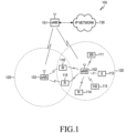
- FIGURE 1 illustrates an example wireless network 100 according to this disclosure.
- the embodiment of the wireless network 100 shown in FIGURE 1 is for illustration only. Other embodiments of the wireless network 100 could be used without departing from the scope of this disclosure
- the wireless network 100 includes an eNodeB (eNB) 101, an eNB 102, and an eNB 103.
- the eNB 101 communicates with the eNB 102 and the eNB 103.
- the eNB 101 also communicates with at least one Internet Protocol (IP) network 130, such as the Internet, a proprietary IP network, or other data network.
- IP Internet Protocol
- the eNB 102 provides wireless broadband access to the network 130 for a first plurality of user equipments (UEs) within a coverage area 120 of the eNB 102.
- the first plurality of UEs includes a LTE 111, which may be located in a small business (SB); a UE 112, which may be located in an enterprise (E); a UE 113, which may be located in a WiFi hotspot (HS); a UE 114, which may be located in a first residence (R); a UE 115, which may be located in a second residence (R); and a LTE 116, which may be a mobile device (M) like a cell phone, a wireless laptop, a wireless PDA, or the like.
- M mobile device
- the eNB 103 provides wireless broadband access to the network 130 for a second plurality of UEs within a coverage area 125 of the eNB 103.
- the second plurality of UEs includes the UE 115 and the UE 116.
- one or more of the eNBs 101-103 may communicate with each other and with the UEs 111-116 using 5G, LTE, LTE-A, WiMAX, or other advanced wireless communication techniques.
- eNodeB eNodeB
- eNB base station
- access point eNodeB
- eNodeB and eNB are used in this patent document to refer to network infrastructure components that provide wireless access to remote terminals.
- UE user equipment
- mobile station such as a mobile telephone or smartphone
- remote terminal such as a desktop computer or vending machine
- Dotted lines show the approximate extents of the coverage areas 120 and 125, which are shown as approximately circular for the purposes of illustration and explanation only. It should be clearly understood that the coverage areas associated with eNBs, such as the coverage areas 120 and 125, may have other shapes, including irregular shapes, depending upon the configuration of the eNBs and variations in the radio environment associated with natural and man-made obstructions. As described in more detail below, one or more of eNB 101, eNB 102, and eNB 103 are configured to perform or support an inter-eNB CoMP JT scheme as described herein.
- FIGURE 1 illustrates one example of a wireless network 100
- the wireless network 100 could include any number of eNBs and any number of UEs in any suitable arrangement.
- the eNB 101 could communicate directly with any number of UEs and provide those UEs with wireless broadband access to the network 130.
- each eNB 102-103 could communicate directly with the network 130 and provide UEs with direct wireless broadband access to the network 130.
- the eNB 101, 102, and/or 103 could provide access to other or additional external networks, such as external telephone networks or other types of data networks.
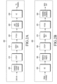
- FIGURES 2A and 2B illustrate example wireless transmit and receive paths according to this disclosure.
- a transmit path 200 may be described as being implemented in an eNB (such as eNB 102), while a receive path 250 may be described as being implemented in a UE (such as UE 116).
- the receive path 250 could be implemented in an eNB and that the transmit path 200 could be implemented in a LTE.
- the transmit path 200 and receive path 250 are configured to perform or support an inter-eNB CoMP JT scheme as described herein.
- the transmit path 200 includes a channel coding and modulation block 205, a serial-to-parallel (S-to-P) block 210, a size N Inverse Fast Fourier Transform (IFFT) block 215, a parallel-to-serial (P-to-S) block 220, an add cyclic prefix block 225, and an up-converter (UC) 230.
- S-to-P serial-to-parallel
- IFFT Inverse Fast Fourier Transform
- P-to-S parallel-to-serial
- UC up-converter
- the receive path 250 includes a down-converter (DC) 255, a remove cyclic prefix block 260, a serial-to-parallel (S-to-P) block 265, a size N Fast Fourier Transform (FFT) block 270, a parallel-to-serial (P-to-S) block 275, and a channel decoding and demodulation block 280.
- DC down-converter
- S-to-P serial-to-parallel
- FFT Fast Fourier Transform
- P-to-S parallel-to-serial
- the channel coding and modulation block 205 receives a set of information bits, applies coding (such as a low-density parity check (LDPC) coding), and modulates the input bits (such as with Quadrature Phase Shift Keying (QPSK) or Quadrature Amplitude Modulation (QAM)) to generate a sequence of frequency-domain modulation symbols.
- coding such as a low-density parity check (LDPC) coding
- modulates the input bits such as with Quadrature Phase Shift Keying (QPSK) or Quadrature Amplitude Modulation (QAM)
- QPSK Quadrature Phase Shift Keying
- QAM Quadrature Amplitude Modulation
- the serial-to-parallel block 210 converts (such as de-multiplexes) the serial modulated symbols to parallel data in order to generate N parallel symbol streams, where N is the IFFT/FFT size used in the eNB 102 and the LTE 116.
- the size N IFFT block 215 performs an IFFT operation on the N parallel symbol streams to generate time-domain output signals.
- the parallel-to-serial block 220 converts (such as multiplexes) the parallel time-domain output symbols from the size N IFFT block 215 in order to generate a serial time-domain signal.
- the add cyclic prefix block 225 inserts a cyclic prefix to the time-domain signal.
- the up-converter 230 modulates (such as up-converts) the output of the add cyclic prefix block 225 to an RF frequency for transmission via a wireless channel.
- the signal may also be filtered at baseband before conversion to the RF frequency.
- a transmitted RF signal from the eNB 102 arrives at the UE 116 after passing through the wireless channel, and reverse operations to those at the eNB 102 are performed at the LTE 116.
- the down-converter 255 down-converts the received signal to a baseband frequency
- the remove cyclic prefix block 260 removes the cyclic prefix to generate a serial time-domain baseband signal.
- the serial-to-parallel block 265 converts the time-domain baseband signal to parallel time domain signals.
- the size N FFT block 270 performs an FFT algorithm to generate N parallel frequency-domain signals.
- the parallel-to-serial block 275 converts the parallel frequency-domain signals to a sequence of modulated data symbols.
- the channel decoding and demodulation block 280 demodulates and decodes the modulated symbols to recover the original input data stream.
- Each of the eNBs 101-103 may implement a transmit path 200 that is analogous to transmitting in the downlink to UEs 111-116 and may implement a receive path 250 that is analogous to receiving in the uplink from UEs 111-116.
- each of UEs 111-116 may implement a transmit path 200 for transmitting in the uplink to eNBs 101-103 and may implement a receive path 250 for receiving in the downlink from eNBs 101-103.
- FIGURES 2A and 2B can be implemented using only hardware or using a combination of hardware and software/firmware.
- at least some of the components in FIGURES 2A and 2B may be implemented in software, while other components may be implemented by configurable hardware or a mixture of software and configurable hardware.
- the FFT block 270 and the IFFT block 215 may be implemented as configurable software algorithms, where the value of size N may be modified according to the implementation.
- variable N may be any integer number (such as 1, 2, 3, 4, or the like) for DFT and IDFT functions, while the value of the variable N may be any integer number that is a power of two (such as 1, 2, 4, 8, 16, or the like) for FFT and IFFT functions.
- FIGURES 2A and 2B illustrate examples of wireless transmit and receive paths
- various changes may be made to FIGURES 2A and 2B .
- various components in FIGURES 2A and 2B could be combined, further subdivided, or omitted and additional components could be added according to particular needs.
- FIGURES 2A and 2B are meant to illustrate examples of the types of transmit and receive paths that could be used in a wireless network. Any other suitable architectures could be used to support wireless communications in a wireless network.
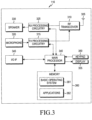
- FIGURE 3 illustrates an example UE 116 according to this disclosure.
- the embodiment of the UE 116 illustrated in FIGURE 3 is for illustration only, and the UEs 111-115 of FIGURE 1 could have the same or similar configuration.
- UEs come in a wide variety of configurations, and FIGURE 3 does not limit the scope of this disclosure to any particular implementation of a UE.
- the UE 116 includes an antenna 305, a radio frequency (RF) transceiver 310, transmit (TX) processing circuitry 315, a microphone 320, and receive (RX) processing circuitry 325.
- the UE 116 also includes a speaker 330, a main processor 340, an input/output (I/O) interface (IF) 345, a keypad 350, a display 355, and a memory 360.
- the memory 360 includes a basic operating system (OS) program 361 and one or more applications 362.
- OS basic operating system
- the RF transceiver 310 receives, from the antenna 305, an incoming RF signal transmitted by an eNB of the network 100.
- the RF transceiver 310 down-converts the incoming RF signal to generate an intermediate frequency (IF) or baseband signal.
- the IF or baseband signal is sent to the RX processing circuitry 325, which generates a processed baseband signal by filtering, decoding, and/or digitizing the baseband or IF signal.
- the RX processing circuitry 325 transmits the processed baseband signal to the speaker 330 (such as for voice data) or to the main processor 340 for further processing (such as for web browsing data).
- the TX processing circuitry 315 receives analog or digital voice data from the microphone 320 or other outgoing baseband data (such as web data, e-mail, or interactive video game data) from the main processor 340.
- the TX processing circuitry 315 encodes, multiplexes, and/or digitizes the outgoing baseband data to generate a processed baseband or IF signal.
- the RF transceiver 310 receives the outgoing processed baseband or IF signal from the TX processing circuitry 315 and up-converts the baseband or IF signal to an RF signal that is transmitted via the antenna 305.
- the main processor 340 can include one or more processors or other processing devices and execute the basic OS program 361 stored in the memory 360 in order to control the overall operation of the UE 116.
- the main processor 340 could control the reception of forward channel signals and the transmission of reverse channel signals by the RF transceiver 310, the RX processing circuitry 325, and the TX processing circuitry 315 in accordance with well-known principles.
- the main processor 340 includes at least one microprocessor or microcontroller.
- the main processor 340 is also capable of executing other processes and programs resident in the memory 360, such as operations for an inter-eNB CoMP JT communications as described herein.
- the main processor 340 can move data into or out of the memory 360 as required by an executing process.
- the main processor 340 is configured to execute the applications 362 based on the OS program 361 or in response to signals received from eNBs or an operator.
- the main processor 340 is also coupled to the I/O interface 345, which provides the UE 116 with the ability to connect to other devices such as laptop computers and handheld computers.
- the I/O interface 345 is the communication path between these accessories and the main controller 340.
- the main processor 340 is also coupled to the keypad 350 and the display unit 355.
- the operator of the UE 116 can use the keypad 350 to enter data into the UE 116.
- the display 355 may be a liquid crystal display or other display capable of rendering text and/or at least limited graphics, such as from web sites.
- the memory 360 is coupled to the main processor 340.
- Part of the memory 360 could include a random access memory (RAM), and another part of the memory 360 could include a Flash memory or other read-only memory (ROM).
- RAM random access memory
- ROM read-only memory
- FIGURE 3 illustrates one example of LTE 116
- various changes may be made to FIGURE 3 .
- various components in FIGURE 3 could be combined, further subdivided, or omitted and additional components could be added according to particular needs.
- the main processor 340 could be divided into multiple processors, such as one or more central processing units (CPUs) and one or more graphics processing units (GPUs).
- FIGURE 3 illustrates the UE 116 configured as a mobile telephone or smartphone, UEs could be configured to operate as other types of mobile or stationary devices.
- CoMP Coordinatd MultiPoint
- JT Joint transmission
- Rel-11 inter-site CoMP was designed assuming ideal backhaul (e.g. fiber), where latency was negligible and the backhaul capacity was not an issue. Under the ideal backhaul assumption, it was feasible to implement a centralized controller/scheduler architecture where a centralized controller/scheduler was responsible for the scheduling decision of all TPs participating in CoMP. It was also feasible to implement a distributed scheduler architecture in which case the ideal backhaul enabled very tight coordination between schedulers of different sites.
- An overview of 3GPP LTE Rel-11 CoMP can be found in Juho Lee et al, "Coordinated Multipoint Transmission and Reception in LTE-Advanced Systems", IEEE Communications Magazine, Vol 50, Issue 11, Page(s) 44-50, Nov 2012 .
- the inter-eNB CoMP framework can be designed to support an inter-eNB CoMP JT scheme where each evolved Node B (eNB) participating as a TP in the CoMP transmission can independently schedule and transmit downlink shared channel (DL-SCH) data to a UE on the same carrier frequency.
- eNB evolved Node B
- DL-SCH downlink shared channel
- n-th TP the TP with the n-th largest average DL received power.
- Table 1 illustrates a TP selection ratio.
- the first observation is that the 1 st TP (the largest received power) can be selected most of the time for DPS. This implies that the channel condition from the first TP can be more favorable compared to the other TPs most of the time.
- Table 1 TP selection ratio Clustered 82.66% 13.33% 4.01% Uniform 81.47% 14.42% 4.11% Clustered 89.24% 19.17% 1.59% Uniform 87.32% 10.75% 1.93%
- RU Resource Utilization
- Inter-eNB CoMP JT can be beneficial in many scenarios.
- inter-eNB CoMP JT can be beneficial in the case where the UE's channel can only sustain rank-1 transmission from the 1 st TP for most of the time.
- inter-eNB CoMP JT with a second transmission from the 2 nd TP can improve average cell edge throughput.
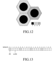
- inter-eNB CoMP JT can be beneficial in the case where the UE's channel can support rank-2 transmissions from the 1 st TP for most of the time (HetNet scenario-CoMP scenario 3 in FIGURE 6 ).
- inter-eNB CoMP JT with additional Physical Downlink Shared Channel (PDSCH) transmission in non-overlapping resource blocks can improve the average cell throughput.
- PDSCH Physical Downlink Shared Channel
- the typical UE can support only up to rank-2 reception.
- the typical UE can be assigned multiple PDCCH/EPDCCHs which requires larger PDCCH/EPDCCH capacity , low to medium network loads are targeted.
- a UE can typically be connected to one eNB in LTE.
- FIGURE 7 illustrates this single connectivity where the data is going from the S-GW, through the eNodeB that the UE is connected to, and then on to the UE.
- FIGURE 8A illustrates an embodiment of CN split architecture according to this disclosure. Specifically, FIGURE 8A illustrates an embodiment of CN split architecture so that when each of the eNodeBs transmits data to the LTE, the LTE can receive the data directly from the S-GW.
- FIGURE 8A illustrates an embodiment of Radio Access Network (RAN) split architecture according to this disclosure.
- RAN split architecture one eNB can receive the data for the UE directly from the S-GW and can transmit a part of the data received to the UE. Additionally with RAN split architecture, the eNB can forward other parts of the data over the X2 interface to one or more other eNBs for transmission.
- Physical channel processing involves PDSCH scrambling.
- PDSCH scrambling for each codeword q there is a block of bits b q 0 , ... , b q M bit q ⁇ 1 , where M bit q is the number of bits in codeword q transmitted on the physical channel in one subframe.
- UE-specific reference signals For Rel-10/11 LTE Downlink Power Allocation with transmission mode 9 or 10, if UE-specific reference signals (RSs) can be present in the physical resource blocks (PRBs) upon which the corresponding physical downlink shared channel (PDSCH) is mapped, the UE can assume the ratio of PDSCH energy per resource element (EPRE) to UE-specific RS EPRE within each OFDM symbol containing UE-specific RS is 0 dB for a number of transmission layers less than or equal to two. Otherwise, the UE can assume the ratio of PDSCH energy per resource element (EPRE) to DE-specific RS EPRE within each OFDM symbol containing UE-specific RS is -3 dB.
- EPRE PDSCH energy per resource element
- the primary CoMP eNB can be the eNB that a UE is attached to upon initial access.
- the secondary CoMP eNBs can be the one or more eNBs that are involved in the inter-eNB CoMP JT scheme apart from the primary CoMP eNB.
- the eNBs that participate in the inter-eNB CoMP scheme can be referred to as the CoMP eNBs and the LTE that is involved in the inter-eNB CoMP scheme can be called the CoMP UE.
- CoMP eNB a CoMP eNB as a TP.
- FIGURE 10 illustrates an embodiment of a high level inter-eNB CoMP JT method according to this disclosure.
- the method can involve the network (such as the primary CoMP eNB) determining or identifying the set of eNBs that are suitable to or configured to participate in the inter-eNB CoMP JT.
- the method can also involve setting up the necessary configurations between the eNBs and configuring or reconfiguring the UEs depending on UE mobility or the change in the channel conditions.
- the primary CoMP eNB can implement CoMP resource management (CRM) configurations.
- CRM CoMP resource management
- the primary CoMP eNB implements CRM configurations to determine the set of eNBs (or TPs) that are suitable to participate in inter-eNB CoMP JT.
- the primary CoMP eNB determines the set of eNBs (or TPs) that are suitable to participate in inter-eNB CoMP JT based on UE measurement reports of the signals transmitted from the eNB(s).
- the signals to be measured by the UE for CRM can be CSI-RSs, CRS, discovery signals (such as for small cells), or the like.
- CSI-RSs For convenience, we shall refer to these signals within this disclosure as CSI-RSs without limiting these signals to only CSI-RSs. Additionally, it can be assumed that the neighboring eNBs can exchange information about the respective CSI-RS resources beforehand, either over X2 transmissions or via OAM transmissions. Hence, the primary CoMP eNB can know the set of CSI-RS resources that are configured to the UE for the purposes of CRM.
- the UE can measure the CoMP resource measurement (CRM) and report the CRM measurement to the primary CoMP eNB.
- CRM CoMP resource measurement
- the method for CRM measurement and reporting by the UE can be similar to the CRM procedure disclosed in Rel-11 (see for example, Juho Lee et al, "Coordinated Multipoint Transmission and Reception in LTE-Advanced Systems", IEEE Communications Magazine, Vol. 50, Issue 11, Page(s) 44-50, Nov 2012 .)
- steps 1005 and 1010 can be used by a primary CoMP eNB to determine the set of eNBs (or TPs) that are suitable to participate in inter-eNB CoMP JT
- the primary CoMP eNB can also use any other means available to determine the set of eNBs (or TPs) that are suitable to participate in inter-eNB CoMP JT.
- an alternative method to the CRM method can be for the primary CoMP eNB to rely on the measurements of UL signals such as the sounding reference signals (SRS) or other available location information such as the GPS information or the measurement from positioning reference signals as disclosed in 3GPP TS 36.355 V11.0.0 (2012-09 ).
- SRS sounding reference signals
- the primary CoMP eNB can decide to initiate inter-eNB CoMP JT operation.
- the primary CoMP eNB can decide to initiate inter-eNB CoMP JT based on the UE measurement reports.
- the primary CoMP eNB can choose the set of neighboring eNBs. In the case of Core Network (CN) split higher layer architecture, this decision can be conveyed to the core network so that eNBs selected by the primary CoMP eNB can start to receive data for the UE from the serving gateway.
- CN Core Network
- inter-eNB CoMP resource negotiation between eNBs can take place.
- Inter-eNB CoMP resource negotiations can include allowing the eNB (such as the secondary CoMP eNBs) selected or chosen by the primary CoMP eNB to determine the allocation of the CoMP resources for each of the selected or chosen eNBs.
- inter-eNB CoMP resource negotiation messages can be exchanged between the selected or chosen eNBs over an X2 interface.
- the primary CoMP eNB can make resource requests to the secondary CoMP eNBs as shown in step 1020 and the secondary CoMP eNBs can make resource allocations to the primary CoMP eNB as shown in step 1025.
- CoMP resources can refer to one or more of the following: physical resource blocks (PRBs), subframes, DM-RS ports, virtual C-RNTI, or the like.
- data to be scheduled and transmitted from the secondary CoMP eNBs can be forwarded from the primary CoMP eNB to the one or more secondary CoMP eNBs.
- Data forwarding at least in this manner can be particularly relevant for the RAN split higher layer architecture.
- RRC configuration can take place for inter-eNB CoMP.
- RRC configuration for inter-eNB CoMP can comprise channel state information - reference signal (CSI-RS) resource configuration for inter-eNB CoMP.
- CSI-RS channel state information - reference signal
- each TP can typically be associated with a CSI-RS resource configuration.
- N CSI-RS resources can be configured to the UE.
- the CSI feedback mode and other CSI measurement assumptions for each CSI-RS resource can be configured separately for each TP.
- the LTE can measure the "N" configured CSI-RS resources and feedback CSI to each eNB.
- each eNB involved in inter-eNB CoMP can receive the CSI corresponding to the DL channel between the eNB and the UE.
- RRC configuration for inter-eNB CoMP can comprise quasi co-location (QCL) configuration for inter-eNB CoMP.
- QCL quasi co-location
- Rel-11 QLC behavior B is typically applicable for inter-eNB CoMP, although it is possible for certain deployment scenario for the network to assume QCL behavior A also described in 7.1.10 of 3GPP TS 36.213 V11.1.0 (2012-12 ).
- RRC configuration for inter-eNB CoMP can comprise PDSCH rate matching configuration for inter-eNB CoMP. Similar to Rel-11 CoMP, the cell-specific reference signal (CRS) rate matching pattern, multimedia broadcast multicast service single frequency network (MBSFN) subframe configuration, PDSCH starting symbol, and zero power (ZP) CSI-RS for each PDSCH can be different.
- CRS cell-specific reference signal
- MMSFN multimedia broadcast multicast service single frequency network
- ZP zero power
- the primary CoMP eNB and one or more secondary CoMP eNBs can perform scheduling and can carry out transmissions using pre-negotiated resources.
- the primary CoMP eNB can carry out transmissions through PDCCH/EPDCCH or PDSCH and one or more second CoMP eNBs can carry out transmissions through EPDCCH or PDSCH.
- Step 1040 will be discussed further herein at least with respect to independent downlink (DL) assignment for each eNB.
- additional resource negotiations or renegotiations between CoMP eNBs can occur.
- the additional resource negotiations or renegotiations can occur because of, for example, UE mobility or channel condition changes.
- the inter-eNB CoMP operation can terminate.
- the primary CoMP eNB and one or more secondary CoMP eNBs can perform scheduling and can carry out transmissions using pre-negotiated resources. This step can be executed with independent DL assignments from each eNB.
- each of the N TPs can transmit a single Transport Block (TB) to the LTE on the same carrier.
- TB Transport Block
- each transport block can be carried by a PDSCH.
- each of the N TPs can transmit up to two TBs to the LTE on the same carrier. For example, one or two TBs can be carried by a PDSCH.
- An advantage of independent DL assignments for each eNB where each of the N TPs can transmit a single TB to the UE on the same carrier can be that the number of TBs to be received by the UE per carrier can be reduced. Furthermore, an advantage of independent DL assignments for each eNB where each of the N TPs can transmit up to two TBs to the UE on the same carrier can be that 3GPP LTE methods (such as a 3GPP LTE Rel-8 method) can be reused for each TP. However, with at least some 3GPP LTE methods the total number of TBs that need to be processed by the UE can be more than 2 per carrier frequency.
- each TP can perform independent scheduling of PDSCH.
- each of the N TPs can independently construct Dynamic Control Information (DCI) containing the scheduling information for the PDSCH carrying its transport block.
- DCI Dynamic Control Information
- Up to N DCIs can be carried by the corresponding number of PDCCHs/EPDCCHs.
- the UE configured with inter-eNB CoMP JT can be required to monitor up to N PDCCHs/EPDCCHs for DL assignments in a subframe of a carrier simultaneously.
- the HARQ processes for the DL assignments can also be independent.
- inter-eNB CoMP JT can be initiated by the configuration of a new transmission mode (such as a future transmission mode 11).
- the inter-eNB CoMP JT operation can be terminated when the transmission mode configured to the UE is no longer the new transmission mode.
- the UE can recognize the configuration of inter-eNB CoMP JT operation through the configuration of multiple transmission modes simultaneously for a particular carrier. In other words, if the UE is configured with more than one transmission mode for a carrier, then the UE has been configured with inter-eNB CoMP JT. Conversely, if the UE is not configured with more than one transmission mode for a carrier, then the UE has not been configured with inter-eNB CoMP JT.
- the number of transmission modes implies the number of TPs involved in the inter-eNB CoMP JT operation and hence the maximum number of the DL assignments that can be expected by the UE.
- the total number of TPs, N, that participate in inter-eNB CoMP JT can be capped in order to limit the impact on UE complexity.
- the number N that can be handled by the UE can be signaled as a part of the UE capability signaling to the network.
- multiple cell RNTIs can be configured for inter-eNB CoMP.
- the same C-RNTI cannot be used by two UEs that are RRC-connected to the same cell simultaneously.
- the secondary CoMP eNodeB is a stand-alone eNodeB, (such that it is capable of operating as a stand-alone cell handling its own UEs) the C-RNTI assigned by the primary CoMP eNodeB for a CoMP UE can happen to also be used by the secondary CoMP eNodeB for another UE.
- the secondary CoMP eNodeB also uses the C-RNTI used by the primary CoMP eNodeB to serve the CoMP UE, then the same C-RNTI could be used by two or more UEs in the same carrier. However, when the same C-RNTI is used by two or more UEs in the same carrier, a C-RNTI collision problem can occur.
- the LTE can be configured with a different C-RNTI for different TPs.
- the UE can use the C-RNTI to determine the UE-specific search space for PDCCH/EPDCCH.
- the LTE can use the C-RNTI to determine the UE-specific search space for PDCCH/EPDCCH by scrambling the cyclic redundancy check CRC of the PDCCH/EPDCCH and the PDSCH for the TP.
- the primary CoMP eNB can determine the C-RNTI of choice of the secondary CoMP eNB and configure the C-RNTI associated with the UE.
- the secondary CoMP eNB can be required to select a C-RNTI and forward the selected C-RNTI (such as over an X2 interface) to the primary CoMP eNB. This can allow the primary CoMP eNB to include the new C-RNTI in the inter-eNodeB CoMP higher layer configuration message to the CoMP UE.
- the primary CoMP eNB can be required to forward the C-RNTI value (such as over an X2 interface) that the primary CoMP eNB uses for the CoMP LTE to the one or more secondary CoMP eNBs.
- the secondary CoMP eNB can check or verify if the C-RNTI has already been used for one of the UEs served by the secondary CoMP eNB. If the forwarded C-RNTI has already been used, the secondary CoMP eNB can choose a new C-RNTI for the CoMP UE.
- the secondary CoMP eNB can then forward the new C-RNTI to the primary CoMP eNB (such as over an X2 interface) so that the primary CoMP eNB can include the new C-RNTI in the inter-eNB CoMP higher layer configuration message to the CoMP UE.
- the secondary CoMP eNB can merely acknowledge the reception of the forwarded C-RNTI to the primary CoMP eNB (such as over an X2 interface).
- the primary CoMP eNB upon receiving the acknowledgement, can then assume that the earlier forwarded C-RNTI will also be used by the secondary CoMP eNodeB.
- the inter-eNodeB CoMP configuration message to the UE contains the C-RNTI value that the LTE shall assume for the secondary CoMP eNB.
- C-RNTI value that the LTE shall assume for the secondary CoMP eNB.
- a collision of C-RNTIs can be rare.
- signaling of C-RNTI value for secondary CoMP eNB to the UE may not always be present. If the signaling of the C-RNTI is absent, the CoMP UE can assume the same C-RNTI for the secondary CoMP eNodeB as for the primary CoMP eNodeB.
- the chosen C-RNTI by the secondary CoMP eNB can be the same as C-RNTI used for the primary CoMP eNB.
- additional coordination between the eNBs can be used to partition the C-RNTI set into non-overlapping subsets so that each subset can be assigned to one of the eNBs participating in inter-eNB CoMP. The additional coordination can ensure that the C-RNTI used for different TPs are different.
- PRBs physical resource blocks
- TPs may not be allowed to be overlapping in time or frequency.
- coordination between eNBs on the frequency resource partition or the time resources partition can be required to ensure that the PRBs for PDSCH do not overlap in time or frequency.
- the primary CoMP eNB can be given the authority to determine its preferred time resources or preferred frequency resources for the UE.
- the primary CoMP eNB can send messages to the one or more secondary CoMP eNBs (such as over an X2 interface) informing the one or more secondary CoMP eNBs of the time-frequency resources that the one or more secondary CoMP eNBs should avoid using with the UE or, equivalently, the time-frequency resources that the one or more secondary CoMP eNBs should use with the LTE (such as the CoMP UE).
- the primary CoMP eNB can provide a message to a secondary CoMP eNB indicating, for example, that PRB#1 through PRB#10 should be avoided by the secondary CoMP eNB for the purpose of scheduling to the CoMP UE.
- the same message from the primary CoMP eNB to the secondary CoMP eNB can be limited to an indication that PRB#1 through PRB#10 should be avoided by the secondary CoMP eNB for the purpose of scheduling to the CoMP UE so that the secondary CoMP eNB can utilize PRB#1 through PRB#10 for the other UEs that the secondary CoMP eNB is serving at the same time.
- This indication limitation of the message from the primary CoMP eNB to a secondary CoMP eNB can allow for the reuse of PRBs by the secondary CoMP eNB to other UEs without generating excessive and unwanted interference to the CoMP UE, for example when the other UEs are far away from the CoMP UE. It should be understood that a message indicating a limitation of particular set of PRBs can be for all subframes or for only a subset of all of the subframes.
- N TPs can be configured to perform inter-eNB CoMP JT for a UE.
- the single secondary CoMP eNB needs only to take into account the decision of the primary CoMP eNB.
- N>2 two or more secondary CoMP eNBs are present.
- the eNB with the higher average received signal power can get the priority to indicate its preferred time frequency resources over another eNB with a relatively lower average received signal power.
- the priority order of the eNBs can be determined based on the reference signal received power (RSRP) / channel state information (CSI) - RSRP measured by the LTE of the eNBs. It should be understood that other signal measurement metrics that also reflect the average received signal strength or channel quality can be used in addition to or as an alternative to RSRP/CSI-RSRP.
- the RSRP/CSI-RSRP reports can be sent to the primary CoMP eNB or the one or more secondary CoMP eNBs. In this case where the RSRP/CSI-RSRP measurement reports are only sent to the primary CoMP eNB, then the primary CoMP eNB can inform the other secondary CoMP eNBs of the priority order. Additionally, in the case where the RSRP/CSI-RSRP measurement reports are sent to all eNBs, then each eNB can determine its own priority from the reports.
- each CoMP eNB can be free to assign the DM-RS ports for the CoMP UE.
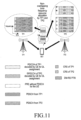
- FIGURE 11 illustrates an embodiment of non-overlapping PRB allocations for PDSCH according to this disclosure.
- CoMP eNBs can utilize frequency-domain-based resource partitioning.
- Frequency-domain-based resource partitioning methods (such as those defined for LTE Rel. 8/9), also known as Inter-Cell Interference Coordination (ICIC), define mechanisms in which a cell's PRBs are partitioned into, for example, two sets. For example, a first set of PRBs can be reused in all neighboring cells and can be typically scheduled to UEs close to the eNB because they are typically much less affected by inter-cell interference than UEs at the edge of the cell.
- the PRB partitions between the CoMP eNBs can be defined by a relative narrowband transmit power (RNTP) indicator which can be exchanged over the X2 interface between neighboring eNBs.
- the RNTP indicator can be a bitmap with each bit corresponding to a RB and can indicate whether or not the cell is planning to keep the RB's transmit power below an upper limit.
- a CoMP eNB may not schedule data for the target UEs in the RBs indicated to be used by the other CoMP eNB.
- the value of the transmit power upper limit and the period by which the indicator is valid can be configurable and can be set by the primary CoMP eNB based upon the related inter-eNB CoMP JT parameters related to expected transmit powers for the TPs and the estimated duration of the inter-eNB CoMP configuration.
- CoMP eNBs can utilize time-domain-based resource partitioning.
- Time-domain partitions between the CoMP eNBs (such as LTE Rel-10 time-domain-based resource partitioning) also known as enhanced ICIC (eICIC) can partition subframes into two sets. For example, a first set of subframes can be used by all cells, while a second set of subframes can be reserved for data transmissions from only certain cells (such as small cells).
- ABSs Almost Blank Subframes
- the small cells can utilize the ABSs to schedule UEs with low SINR (typically at the cell-edge) to improve their throughput since the macro-cell interference is largely removed.
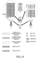
- the periodicities of the ABS patterns can be designed to align with the synchronous uplink HARQ operation. For example, for an FDD network, the periodicity is a multiple of 40ms.
- FIGURE 13 illustrates an embodiment of time-domain-based eICIC resource allocation according to this disclosure. Specifically, FIGURE 13 illustrates an eICIC ABS pattern with 2 ABSs for every frame.
- the ABS configurations can be exchanged between eNBs via the X2 interface using an ABS Pattern message.
- the ABS Pattern can be a bitmap which indicates whether or not a cell is planning to keep the transmit power below an upper limit.
- the ABS Pattern bitmap can make an indication as whether or not a cell is planning to keep transmit power below an upper limit on a subframe-by-subframe basis.
- a CoMP eNB can restrict scheduling data for the target UEs to the subframes indicated by another CoMP eNB to be non-ABS subframes or ABS subframes, respectively, depending on whether the sending or receiving CoMP eNB can transmit on the ABS subframes.
- the value of the transmit power upper limit and the periodicity of the ABS patterns can be configurable and can be set by the primary CoMP eNB based upon the related inter-eNB CoMP JT parameters related to expected transmit powers for the TPs and the estimated duration of the inter-eNB CoMP configuration.
- PRBs physical resource blocks
- PRBs for PDSCHs allocated by the TPs can be independently allocated and can be allowed to overlap in time and frequency (such as with spatial multiplexing). The overlap can be partial, which relaxes the scheduling restriction in terms of time/frequency resources of each TP.
- DM-RS ports used by each TP for the overlapping resource blocks for PDSCH may not have the same port index (such that the DM-RS ports for two different TPs are orthogonal).
- DM-RS port assignments for PDSCH can be coordinated beforehand among the CoMP eNBs.
- independent PRB allocation can be beneficial when, for example, the primary CoMP eNB is only able to transmit with low rank (such as a lower rank than what the LTE is capable of receiving) most of the time due to poor channel conditions.
- the UE throughput can be increased.
- DM-RS Port 7 can be allocated for a first eNB (such as eNB1) while DM-RS Port 8 (P8) can be allocated for a second eNB (such as eNB2).
- first eNB such as eNB1
- second eNB such as eNB2
- only one transmission layer can be transmitted from each TP.
- the maximum number of transmission layers per PRB is 2.
- the DM-RS overhead that may be assumed by the UE for every PRB-pair assigned can be 12 resource elements (REs).
- the PDSCH energy per resource element (EPRE) to DM-RS EPRE ratio can be assumed by the UE to be always 0 dB.
- the DM-RS port can be indicated in the DCI, (similar to that used for DCI format 2B to be discussed further herein).
- Each DCI indicates that one of the transport blocks can be disabled and the new data indicator (NDI) indicates the DM-RS port as shown below in Table 4.
- Table 4 Antenna port for single-antenna port transmission (one transport block disabled). New data indicator of the disabled transport block Antenna port 0 7 1 a
- a new DCI format (which can be referred to as DCI format 2B') can be modified such that the modulation and coding scheme (MCS), NDI and RV information bits (for a total of 8 bits) for the second transport block can be replaced with one bit to indicate the DM-RS port as illustrated below in Table 5.
- MCS modulation and coding scheme
- NDI NDI
- RV information bits for a total of 8 bits
- Table 5 Antenna port for sinsle-antenna port transmission.
- New DCI bits (DM-RS port and the number of layers) Antenna port 0 7 1 8
- the DM-RS port to receive the PDSCH for a TP can also be semi-statically signaled to the UE.
- higher layer configuration can indicate to the LTE that the PDSCH scheduled from an EPDCCH in a EPDCCH set shall always use DM-RS P8. This may be because the specific EPDCCH and the corresponding PDSCH can always be transmitted from a secondary CoMP eNB that has been assigned DM-RS P8.
- the DM-RS port to receive the PDSCH for a TP can be a higher layer configured to be associated with a CSI-RS resource. Through the indication of the quasi co-located CSI-RS, the DM-RS port to receive the PDSCH can be the DM-RS port associated with the indicated quasi co-located CSI-RS.
- FIGURE 14 illustrates an embodiment of at least partially overlapping PRB allocations for PDSCH according to this disclosure.
- DM-RS P7/8 can be allocated for a first eNB (such as eNB1) while DM-RS P9/10 can be allocated for a second eNB (such as eNB2).
- the maximum number of transmission layers transmitted from each TP can be 1, 2, or 4 and can be different for different TPs.
- the DM-RS overhead that may be assumed by the UE for every PRB-pair assigned can be 24 REs.
- the PDSCH EPRE to DM-RS EPRE ratio can be assumed by the LTE to always be -3 dB.
- the DM-RS port can be indicated in a DCI (such as a DCI format X).
- a DCI such as a DCI format X
- the DCI bits for the one or more antenna ports, scrambling identity, and the number of layers indicated can be interpreted differently.
- Table 6 below illustrates how the DCI bits for the one or more antenna ports, scrambling identity, and the number of layers indicated can be interpreted for eNB1 (such as the primary CoMP eNB) while
- Table 7 illustrates how the DCI bits for the one or more antenna ports, scrambling identity, and the number of layers indicated can be interpreted for eNB2 (such as a secondary CoMP eNB).
- Table 6 The principle behind Table 6 and Table 7 can be to map the DM-RS ports for an eNB to the same code division multiplexing (CDM) group.
- Table 6 Antenna port(s), scrambling identity and number of layers indication for eNB1 (e.g.
- nSCID can be fixed to 0 allowing for improved reliability for rank-2 reception.
- the nSCID can be configured to be either 0 or 1, even for rank 2 transmission, allowing for improved flexibility with MU-MIMO scheduling.
- Table 6 or Table 7 is applicable can depend on where the scheduling DCI is detected or the type of physical downlink control channel. For example, in a first embodiment, if the scheduling DCI is detected in PDCCH, then the UE can assume that Table 6 is applicable. Otherwise, if the scheduling DCI is detected in EPDCCH, then the UE can assume that Table 7 is applicable. In a second embodiment, if the scheduling DCI is detected in a first EPDCCH set, then the UE can assume that Table 6 is applicable. Otherwise, if the scheduling DCI is detected in a second EPDCCH set, then the LTE can assume that Table 7 is applicable. In at least the second embodiment, two eNBs can independently schedule their PDSCHs by relying on their respective EPDCCH sets.
- a first of the two eNBs can utilize the first ePDCCH set while the second of the two eNBs can utilize the second ePDCCH set.
- the set of DM-RS ports (or determining whether to assume Table 6 or Table 7) to receive the PDSCH for a TP can be a higher layer configured to be associated with a CSI-RS resource.
- the set of DM-RS ports to receive the PDSCH can be the DM-RS port associated with the indicated quasi-co-located CSI-RS.
- each of the CoMP eNB are not able to keep track of the other CoMP eNBs scheduling decisions.
- the UE can make the correct assumptions for PDSCH rate matching and for the PDSCH-EPRE-to-DM-RS-EPRE ratio because, for example, if DM-RS P7-10 are assigned by the CoMP eNBs, then the total DM-RS RE overhead for PDSCH can be assumed by the LTE to be 24 REs. Additionally, the UE can also assume that the PDSCH shall be rate matched around these 24 REs for DM-RS, regardless of the actual PDSCH DM-RS port(s) assigned for the particular PRBs.
- the PDSCH-EPRE-to-DM-RS-EPRE ratio (hereinafter the "power ratio") can be assumed by the UE to be -3 dB, regardless of the actual number of transmission layers or rank assigned to the particular PRBs.
- the eNBs can determine beforehand which DM-RS ports can be assigned by a particular CoMP eNB in a subframe. Therefore, higher layer signaling (such as by the primary CoMP eNB) can be provisioned to inform the UE of the appropriate assumptions concerning the PDSCH DM-RS overhead and the power ratio. For example, higher layer signaling (such as RRC signaling) can indicate either 12 or 24 REs as the PDSCH DM-RS overhead assumption and either 0 or -3dB as the power ratio assumption.
- the signaling for the DM-RS RE overhead and the power ratio can be done jointly, such that a single signaled value can jointly indicate both a DM-RS RE overhead and a power ratio.
- a DM-RS RE overhead of 12 RE and 24 RE can be associated with a power ratio of 0 dB and -3dB, respectively.
- Exchanging of time/frequency partitions can be used to aid the CoMP eNBs in aligning their transmissions. For example, if two CoMP eNBs are sending one spatial layer each to the target UE, it may be beneficial for the same downlink resources to be scheduled by both eNBs. Unlike, intra-eNB CoMP where tight scheduling coordination between the TPs can be assumed, in the case of inter-eNB CoMP, extensive scheduling coordination may not be feasible due to rate and latency limitations of the backhaul. Thus, a sufficient level of coordination can be obtained by utilizing the exchanged frequency or time resource partitioning indicators as previously described under non-overlapping PRB allocation.
- the CoMP eNBs can align the resources scheduled by the CoMP eNBs for the target UE with the RBs or subframes that are indicated for utilization by their neighbor eNBs. While this approach can create an implicit level of coordination, the schedulers can remain independent and thus do not require actual knowledge of the resource allocations of their neighbor eNBs.
- obtaining an alignment of transmissions can include sending ICIC or eICIC indicators included with an inter-eNB CoMP coordination message to the CoMP eNBs.
- the ICIC or eICIC indicators can also indicate a target UE or set of target UEs for which the time or frequency information is relevant.
- the CoMP eNBs can implement the ICIC or eICIC partitioning for all the UEs. Conversely, in certain embodiments, the CoMP eNB can implement the ICIC or eICIC partitioning for only those UEs which are being served by the inter-eNB CoMP operation.
- a first CoMP eNB (such as CoMP eNB1) can indicate to a second CoMP eNB (such as CoMP eNB2) via a RNTP that RB1 through RB20 will be utilized for the next few subframes in its scheduling of a first UE (such as UE1) which is being served by an inter-eNB CoMP operation from CoMP eNB1 and CoMP eNB2.
- CoMP eNB2 can choose to schedule the UE1 on RB1 through RB20 first before considering scheduling UE1 on the non-indicated RBs.
- CoMP eNB1 can indicate to CoMP eNB2 via an ABS Pattern that every other subframe will be an ABS for the next 40ms.
- CoMP eNB2 can choose to schedule resources for the targeted users on the non-ABS subframes and resources for non-inter-eNB CoMP users on the remaining subframes. This can allow the CoMP eNBs to improve the probability that the scheduling decisions are aligned without directly exchanging the scheduling information.
- additional ICIC and eICIC techniques can be introduced to mitigate potential interference that can occur due to partial overlap of resource allocations between CoMP eNBs when each of the CoMP eNBs transmits to a different UE.
- a "soft reuse" strategy may be utilized. In this case, the same RNTP or ABS Patterns may be exchanged over the X2 interface, but the CoMP eNBs can only utilize those RNTP or ABS Patterns on an optional basis.
- a first CoMP eNB (such as CoMP eNB1) can indicate to a second CoMP eNB (such as CoMP eNB2) via a RNTP that RB1 through RB20 will be utilized for the next few subframes.
- CoMP eNB2 can choose to only schedule RBs for the targeted users on those RBs once it has exhausted scheduling opportunities on the remaining un-protected RBs.
- CoMP eNB1 can indicate to CoMP eNB2 via an ABS Pattern that every other subframe will be an ABS for the next 40ms.
- CoMP eNB2 can choose to schedule resources for the targeted users on those ABS subframes, but at a lower transmit power than for the non-ABS subframes.
- the CoMP eNB2 can reduce, but not fully eliminating inter-eNB interference for those subframes.
- An alternative to implementing the previously discussed "soft reuse" operation can be for the CoMP eNBs to utilize an ICIC weighting factor 0 ⁇ ⁇ ⁇ 1.
- the CoMP eNB can completely ignore the RNTP or ABS Patterns received from other eNBs and implement independent resources allocation.
- the CoMP eNB can utilize the RNTP or ABS Patterns received from other eNBs in a strict fashion and implement non-overlapping PRB allocation.
- the CoMP eNBs can balance the suggested partitions from the other eNBs with its own scheduling metrics.
- the value of ⁇ can be configured and adjusted independently by each eNB or can be set by the network operator, giving flexibility to adapt to interference and congestion conditions in the network.
- non-overlapping and at least partial overlapping PRB allocation can provide benefits for different channel conditions, in certain embodiments, it can also be beneficial if higher layer signaling (such as RRC) can be provisioned to configure CoMP eNBs to be enabled with at least one of or both non-overlapping and at least partial overlapping PRB allocation.
- higher layer signaling such as RRC
- ICIC or eICIC techniques can be implemented in the network in addition to the inter-eNB CoMP operation, the frequency or time-domain based partitioning information can be implicitly utilized and exchanged between CoMP eNBs.
- ⁇ Load Indication' and 'Resource Status Reporting Initiation' X2 interface procedures can be explicitly indicated and exchanged via a separate X2 coordination message specific to inter-eNB CoMP initialization or configuration.
- each TB transmitted by a TP can correspond to one or more transmission layers.
- the number of transmission layers for each TP or rank can be different.
- the maximum number of transmission layers that can be assigned by the TP to a UE can be the same or fewer than the maximum number of transmission layers that the TP is capable of using.
- the total number of transmission layers that a LTE can receive for a resource block cannot exceed the UE capability. Accordingly, it may be necessary for all TPs involved in the inter-eNB CoMP JT to be informed about the LTE capability.
- the primary CoMP eNB can inform the one or more secondary CoMP eNBs, for example, over the X2 interface, of the maximum number of transmission layers that can be assigned to the UE.
- the primary CoMP eNB can inform the one or more secondary CoMP eNBs, for example, over the X2 interface, of the maximum number of transmission layers that can be assigned to the UE.
- the TPs when the TPs are transmitting PDSCHs in the same set of resource blocks (such as with at least partial overlapping PRB allocation), the sum of the transmission layers by the TPs for the resource blocks cannot exceed the UE capability.
- the maximum number of transmission layers that each TP is allowed to transmit can be coordinated between the TPs beforehand. The coordination between TPs can be performed by messaging over an X2 interface connecting TPs or through a central entity connected to multiple TPs.
- the primary CoMP eNB is the TP with the largest received power and assuming that the UE is likely to use a rank 2 assignment from the primary CoMP eNB with the largest received power, it can be beneficial to allow the primary CoMP eNB to have priority to determine the maximum number of transmission layers for its own transmission. Similar to the time/frequency resource allocation priority handling for non-overlapping PRB allocation, if there are more than two eNBs (such that N > 2), an eNB with the higher received signal power can get the priority to indicate its preferred number of transmission layers over another eNB with relatively lower received signal power.
- eNB n can take into account the decisions of eNB 1 to eNB n-1.
- the priority order of the eNBs can be determined based on the RSRP/CSI-RSRP measured by the UE of the eNBs. Other signal measurement metrics that reflect the received signal strength or channel quality may not be precluded.
- the primary CoMP eNB can inform the other secondary CoMP eNBs of the priority order.
- each eNB can determine its own priority from the reports.
- a first TB such as TB 1
- a second TB such as TB 2
- CW codeword
- TB 1 can be disabled
- TB 2 can be enabled
- TB 2 can also be mapped to CW 0.
- the codeword index (such as 0 or 1) (besides the cell id and the C-RNTI) can be used to initiate the scrambling sequence used for scrambling the transport block bits.
- the TBs from each CoMP eNB can be mapped to a CW index.
- TBs from CoMP eNBs can be mapped to a CW index by assuming that the TB-to-CW mapping is performed as disclosed in the Rel-8 for each PDSCH.
- each CoMP eNB can only transmit one TB to the UE.
- the TB for each PDSCH can be mapped to CW 0 as illustrated below in Table 8.
- each CoMP eNB can transmit up to 2 TBs, so that the TB-to-CW mapping can be implemented as illustrated below in Table 9.
- Table 8 Independent TB-to-CW mapping for each eNB.
- One TB for each eNB Transport block Codeword index Transport block from primary CoMP eNB Codeword 0 Transport block from secondary CoMP eNB Codeword 0
- Table 9 Independent TB-to-CW mapping for each eNB. Up to two TBs for each eNB.
- TBs for example from multiple TPs, can be mapped to the same codeword index in the same subframe in the same carrier.
- the PDSCH scrambling can be performed the same way for different eNB for a given subframe. Scrambling the PDSCHs for different eNB differently (such as uniquely scrambling the PDSCHs) can help with interference randomization.
- scrambling the PDSCHs for different eNBs differently can include configuring a virtual C-RNTI for a UE.
- the LTE can assume that virtual C-RNTI descrambles the PDSCH of one or more secondary eNBs.
- C-RNTI (as such C-RNTI described in Rel-8) can still be used to descramble the PDSCH of the primary CoMP eNB.
- n RNTI corresponds to the C-RNTI associated with the PDSCH transmission from the primary CoMP eNB (eNB 1)
- n VRNTI corresponds to the virtual C-RNTI associated with the PDSCH transmission from the secondary CoMP eNB (eNB 2).
- the virtual C-RNTI can be used only for scrambling the PDSCH. Additionally, in certain embodiments, the virtual C-RNTI can be the same as the C-RNTI configured for a TP such that the virtual C-RNTI can be used to replace the C-RNTI to determine the UE-specific search space for PDCCH/EPDCCH or to replace the C-RNTI for the scrambling of the CRC of the PDCCH/EPDCCH for the secondary CoMP eNB.
- scrambling the PDSCHs for different eNBs can include configuring a Virtual cell id for a UE.
- the LTE can assume that virtual C-RNTI descrambles the PDSCH of one or more secondary eNBs.
- the serving cell id (such as the serving cell id disclosed in Rel-8) can still be used for descrambling the PDSCH of the primary CoMP eNB.
- scrambling the PDSCHs for different eNBs differently can include configuring a virtual C-RNTI and a virtual cell id for a UE.
- c init ⁇ n RNTI ⁇ 2 14 + q ⁇ 2 13 + ⁇ n s / 2 ⁇ ⁇ 2 9 + N ID cell for PDSCH of eNB 1 n VRNTI ⁇ 2 14 + q ⁇ 2 13 + ⁇ n s / 2 ⁇ ⁇ 2 9 + N VID cell for PDSCH of eNB 2
- scrambling the PDSCHs for different eNBs can include mapping the TBs from different CoMP eNB to different codeword indexes. For example, suppose there is one TB transmission from a CoMP eNB, then for two TBs, the TB from the primary CoMP eNB can be mapped to CW 0 and the TB from the secondary CoMP eNB can be mapped to CW 1 as illustrated below in Table 10. In another example, suppose there can be up to two TBs per CoMP eNB, then the TBs from the primary CoMP eNB can be mapped to CW 0 and CW1, while the TBs from the secondary CoMP eNB can be mapped to CW 2 and CW3, as illustrated below in Table 11.
- the TB-to-CW mapping method illustrated in Table 8 or Table 9 can be beneficial for non-overlapping PRB allocation while the TB-to-CW mapping method in Table 10 or Table 11 can be beneficial for at least partial overlapping PRB allocation.
- Higher layer signaling can be used to switch UE assumption between Table 8 or Table 9 and Table 10 or Table 11.
- the UE can also determine how to descramble each PDSCH received.
- the LTE can receive a PDSCH indicating a particular descrambling assumption though dynamic signaling in PDCCH/EPDCCH.
- the UE can receive a PDSCH indicating a particular descrambling assumption through dynamic signaling in PDCCH/EPDCCH using at least one of the virtual C-RNTI, the virtual cell id, or a codeword index.
- the PDSCH indicating a particular descrambling assumption can also be done implicitly.
- the PDSCH can also be descrambled assuming the virtual C-RNTI.
- the type of physical control channel can be used to differentiate the PDSCH descrambling assumption. For example, if the control information for the PDSCH was detected in PDCCH, then the PDSCH (such as the Rel. 8 PDSCH) descrambling can be assumed by the UE. Conversely, if the control information was detected in EPDCCH, then new PDSCH descrambling (such as using at least one of the virtual C-RNTI, the virtual cell id, or a codeword index) can be assumed by the UE instead. In certain embodiments, different EPDCCH sets that can indicate different PDSCH descrambling assumptions can be configured via higher layer signaling.
- the physical control channels can be monitored by the UE so that different CoMP eNB do not overlap in time and frequency.
- monitoring, by the UE, physical control channels so that different CoMP eNBs do not overlap in time and frequency can include transmitting DCI from the primary CoMP eNB in the PDCCH and transmitting DCI from a secondary CoMP eNB in an EPDCCH within an EPDCCH set.
- monitoring, by the UE, physical control channels so that different CoMP eNBs do not overlap in time and frequency can include transmitting DCI from the primary CoMP eNB in an EPDCCH within a first EPDCCH set and transmitting the DCI from a secondary CoMP eNB in an EPDCCH within a second EPDCCH set.
- the two EPDCCH sets may not be assumed to be quasi co-located by the UE.
- the CRS rate matching assumptions may also be different for different EPDCCH set.
- codeword-to-layer mapping cannot be supported because single codeword-to-layer mapping (such as in Rel. 11) is only applicable for retransmission.
- codewordwhen only one codeword is allowed to be transmitted from a CoMP eNB while multi-layer transmission from a CoMP eNB can be supported because inter-eNB CoMP JT is configured (such as a new transmission mode), then the single codeword-to-multiple layers mappings can be used for the initial transmission.
- the codeword-to-layer mapping for spatial multiplexing as illustrated below in Table 12 can be applicable for each CoMP eNB in the inter-eNB CoMP operation for both initial transmission and retransmission.
- DCI formats can be used as an indication for a DM-RS port for a particular CoMP eNB.
- a new DCI format (which can be referred to as DCI format 2B') can be modified such that the modulation and coding scheme (MCS), NDI and RV information bits (for a total of 8 bits) for the second transport block can be replaced with one bit to indicate the DM-RS port as previously illustrated in Table 5.
- MCS modulation and coding scheme
- NDI NDI
- RV information bits for a total of 8 bits
- Table 13 illustrates an embodiment of information that can be transmitted by means of the DCI format 2B'. TABLE 13 The following information is transmitted by means of the DCI format 2B': - Carrier indicator - 0 or 3 bits.
- the field is present according to the definitions in [3GPP TS 36.213].
- Resource allocation header (resource allocation type 0 / type 1) - 1 bit as defined in section 7.1.6 of [3GPP TS 36.213] If downlink bandwidth is less than or equal to 10 PRBs, there is no resource allocation header and resource allocation type 0 is assumed.
- Transport block 1 - Modulation and coding scheme - 5 bits as defined in section 7.1.7 of [3GPP TS 36.213] - New data indicator - 1 bit - Redundancy version - 2 bits - Antenna port(s) - 1 bit - HARQ-ACK resource offset (this field is present when this format is carried by EPDCCH. This field is not present when this format is carried by PDCCH) - 2 bits as defined in section 10.1 of [3GPP TS 36.213] Transport block 1 is mapped to codeword 0. If the number of layers equals one, the antenna port for single-antenna port transmission is according to Table 5. If the number of layers equals two, antenna ports 7 and 8 are used for spatial multiplexing.
- DCI format X can be constructed by removing the MCS, NDI and RV information bits (total of 8 bits) for the second transport block of a legacy DCI format 2D, or by adding a new field of one or more antenna ports and scrambling the identity and the number of layers to the legacy DCI format 1/1A.
- the table indicating antenna port(s), the scrambling identity, and the number of layers can be replaced with Table 6 or Table 7 previously illustrated.
- the transport block can be mapped to codeword 0.
- the codeword-to-layer mapping is specified according to Table 12.
- Table 14 below illustrates an of a DCI format X definition obtained by modifying DCI format 1/2D. TABLE 14
- the following information is transmitted by means of the DCI format X: - Carrier indicator - 0 or 3 bits.
- This field is not present in FDD) - 2 bits - HARQ process number - 3 bits (FDD), 4 bits (TDD) - Antenna port(s), scrambling identity and number of layers - 3 bits as specified in Error! Reference source not found. or Error! Reference source not found.
- nSCID is the scrambling identity for antenna ports 7 and 8 (Error! Reference source not found.) or antenna ports 9 and 10 (Error! Reference source not found.) defined in section 6.10.3.1 of [3GPP TS 36.211] - SRS request - [0-1] bit.
- This field can only be present for TDD and if present is defined in section 8.2 of [3GPP TS 36.213]
- transport block 1 - Modulation and coding scheme - 5 bits as defined in section 7.1.7 of [3GPP TS 36.213] - New data indicator - 1 bit - Redundancy version - 2 bits - PDSCH RE Mapping and Quasi-Co-Location Indicator - 2 bits as defined in sections 7.1.9 and 7.1.10 of [3GPP TS 36.213] - HARQ-ACK resource offset (this field is present when this format is carried by EPDCCH.
- various functions described above are implemented or supported by computer programs, each of which is formed from computer readable program code and embodied in a computer readable medium.
- computer readable program code includes any type of computer code, including source code, object code, and executable code.
- computer readable medium includes any type of medium capable of being accessed by a computer, such as read only memory (ROM), random access memory (RAM), a hard disk drive, a compact disc (CD), a digital video disc (DVD), or any other type of memory.
- ROM read only memory
- RAM random access memory
- CD compact disc
- DVD digital video disc
- a “non-transitory” computer readable medium excludes wired, wireless, optical, or other communication links that transport transitory electrical or other signals.
- a non-transitory computer readable medium includes media where data can be permanently stored and media where data can be stored and later overwritten, such as a rewritable optical disc or an erasable memory device.
Landscapes
- Engineering & Computer Science (AREA)
- Signal Processing (AREA)
- Computer Networks & Wireless Communication (AREA)
- Mobile Radio Communication Systems (AREA)
Claims (7)
- Ein Verfahren zum Ausführen von inter-eNodeB, eNB, koordiniertem Mehrpunkt, CoMP, gemeinsamer Übertragung, JT, zwischen einer CoMP-Benutzerausrüstung, UE, und zwei oder mehr CoMP eNBs, das Verfahren umfasst:Konstruieren, durch eine erste CoMP eNB der zwei oder mehr CoMP eNBs, eines ersten Satzes von Downlink-Steuersinformationen, DCI, umfassend Informationen über die Zuordnungsbeziehung zwischen einem ersten Transportblock, TB, der von der ersten CoMP eNB übertragen wird, und einem ersten Codewort, das mit der Verschlüsselung des ersten TB zusammenhängt, wobei der erste Satz von DCI unabhängig von der ersten CoMP eNB konstruiert wird;Übertragen, durch die erste CoMP eNB, des ersten Satzes von DCI an die CoMP UE,wobei der erste Satz von DCI unabhängige Downlink, DL, Zuweisungen umfasst, die es der ersten CoMP eNB ermöglichen, eine unabhängige Planung eines physischen Downlink-Gemeinschaftskanals, PDSCH, durchzuführen, der mit der ersten CoMP eNB verbunden ist;Konstruieren, durch eine zweite CoMP eNB der zwei oder mehr CoMP eNBs, eines zweiten Satzes von DCI, umfassend Informationen über die Zuordnungsbeziehung zwischen einem zweiten TB, der von der zweiten CoMP eNB übertragen wird, und einem zweiten Codewort, das mit der Verschlüsselung des zweiten TB zusammenhängt, wobei der zweite Satz von DCI unabhängig von der zweiten CoMP eNB konstruiert wird; und Übertragen, durch die zweite CoMP eNB, des zweiten Satzes von DCI an die UE, wobei der zweite Satz von DCI unabhängige DL-Zuweisungen umfasst, die es der zweiten CoMP eNB ermöglichen, eine unabhängige Planung eines PDSCH durchzuführen, der mit der zweiten CoMP eNB verbunden ist,wobei ein Index des ersten Codeworts und ein Index des zweiten Codeworts verwendet werden, um eine Verschlüsselungssequenz zu initiieren, die für die Verschlüsselung von Bits des ersten TB und eine Verschlüsselungssequenz, die für die Verschlüsselung von Bits des zweiten TB verwendet wird, zu initiieren.
- Das Verfahren des Anspruchs 1, wobei jede der zwei oder mehr CoMP eNBs konfiguriert ist, um den TB an die UE auf dem gleichen Träger zu übertragen, wobei der erste TB und der zweite TB dem ersten Codewort und dem zweiten Codewort zugeordnet sind, um zu identifizieren, dass die zwei oder mehr CoMP eNBs den ersten TB und den zweiten TB an die UE übertragen, und wobei jeder der ersten TB und der zweite TB von dem PDSCH getragen wird, der mit einer CoMP eNB verbunden ist, die den jeweiligen ersten TB und den zweiten TB überträgt.
- Das Verfahren des Anspruchs 1, wobei die erste CoMP eNB und die zweite CoMP eNB konfiguriert sind, um weiter einen dritten TB und einen vierten TB an die UE auf dem gleichen Träger zu übertragen.
- Das Verfahren des Anspruchs 3, wobei jeder der ersten TB, der zweite TB, der dritte TB und der vierte TB einem Codewort zugeordnet ist, das jeden der ersten TB, den zweiten TB, den dritten TB und den vierten TB von einem anderen TB unterscheidet, und wobei mindestens ein TB von dem PDSCH getragen wird, der mit der eNB verbunden ist, die den TB überträgt.
- Das Verfahren des Anspruchs 1, ferner umfassend das Initiieren von inter-eNB CoMP JT durch eine Konfiguration eines neuen Übertragungsmodus;
- Das Verfahren des Anspruchs 1, ferner umfassend das Initiieren von inter-eNB CoMP JT, wenn die UE eine gleichzeitige Konfiguration mehrerer Übertragungsmodi für einen einzelnen Träger erkennt.
- Ein System zum Ausführen von inter-eNodeB, eNB, koordiniertem Mehrpunkt, CoMP, gemeinsamer Übertragung, JT, zwischen einer CoMP-Benutzerausrüstung, UE, und zwei oder mehr CoMP eNBs, und angeordnet zum Ausführen einer der Methoden wie definiert in den Ansprüchen 1 bis 6.
Applications Claiming Priority (3)
| Application Number | Priority Date | Filing Date | Title |
|---|---|---|---|
| US201361750701P | 2013-01-09 | 2013-01-09 | |
| US14/148,467 US9923684B2 (en) | 2013-01-09 | 2014-01-06 | Methods to support inter-eNodeB CoMP |
| PCT/KR2014/000205 WO2014109548A1 (en) | 2013-01-09 | 2014-01-08 | Methods to support inter-enodeb comp |
Publications (3)
| Publication Number | Publication Date |
|---|---|
| EP2944034A1 EP2944034A1 (de) | 2015-11-18 |
| EP2944034A4 EP2944034A4 (de) | 2016-11-30 |
| EP2944034B1 true EP2944034B1 (de) | 2024-03-06 |
Family
ID=51060888
Family Applications (1)
| Application Number | Title | Priority Date | Filing Date |
|---|---|---|---|
| EP14737776.6A Active EP2944034B1 (de) | 2013-01-09 | 2014-01-08 | Verfahren zur unterstützung eines inter-enode-b-computers |
Country Status (7)
| Country | Link |
|---|---|
| US (1) | US9923684B2 (de) |
| EP (1) | EP2944034B1 (de) |
| JP (1) | JP6536899B2 (de) |
| KR (1) | KR102164434B1 (de) |
| CN (2) | CN107707342B (de) |
| AU (1) | AU2014205861B2 (de) |
| WO (1) | WO2014109548A1 (de) |
Families Citing this family (81)
| Publication number | Priority date | Publication date | Assignee | Title |
|---|---|---|---|---|
| US9019924B2 (en) | 2012-04-04 | 2015-04-28 | Samsung Electronics Co., Ltd. | High-order multiple-user multiple-input multiple-output operation for wireless communication systems |
| EP2947912A4 (de) * | 2013-01-15 | 2016-08-24 | Fujitsu Ltd | Verfahren, vorrichtung und system zur aushandlung von funktionen zwischen basisstationen |
| CN103945539B (zh) * | 2013-01-18 | 2018-03-09 | 华为终端有限公司 | 一种增强物理下行控制信道的传输方法和装置及通信系统 |
| WO2014121461A1 (zh) * | 2013-02-06 | 2014-08-14 | 华为技术有限公司 | 系统信息调度方法及其装置 |
| US9078241B2 (en) * | 2013-03-22 | 2015-07-07 | Sharp Kabushiki Kaisha | Systems and methods for establishing multiple radio connections |
| JP6359806B2 (ja) * | 2013-05-09 | 2018-07-18 | 株式会社Nttドコモ | 移動通信方法及び無線基地局 |
| US9325482B2 (en) * | 2013-09-10 | 2016-04-26 | Lg Electronics Inc. | Method for coordinated scheduling in wireless communication system and apparatus therefor |
| CN104469960B (zh) * | 2013-09-25 | 2019-12-10 | 中兴通讯股份有限公司 | 调度配置方法与装置 |
| JP6475632B2 (ja) * | 2013-10-29 | 2019-02-27 | 京セラ株式会社 | 通信制御方法、基地局、及びユーザ端末 |
| CN104703212B (zh) * | 2013-12-06 | 2019-07-23 | 索尼公司 | 无线通信系统中的装置、无线通信系统和方法 |
| WO2015137772A1 (en) * | 2014-03-13 | 2015-09-17 | Samsung Electronics Co., Ltd. | Method and apparatus for performing coordinated communication in a communication system |
| CN106105351B (zh) * | 2014-03-20 | 2019-12-06 | 夏普株式会社 | 终端装置、基站装置以及集成电路 |
| US10270495B2 (en) * | 2014-03-24 | 2019-04-23 | Telefonaktiebolaget Lm Ericsson (Publ) | Segmented transfers in mobile networks using coordinated multipoint |
| KR101881428B1 (ko) * | 2014-07-18 | 2018-07-24 | 후아웨이 테크놀러지 컴퍼니 리미티드 | 사용자 장치, 네트워크 노드 및 이의 방법 |
| KR102381159B1 (ko) * | 2014-09-18 | 2022-03-31 | 엘지전자 주식회사 | 다중 안테나 무선 통신 시스템에서 채널 측정을 위한 참조 신호 전송 방법 및 이를 위한 장치 |
| US9538550B2 (en) | 2014-10-03 | 2017-01-03 | Nokia Solutions And Networks Oy | Cooperative uplink reception suitable for non-ideal backhaul |
| US9699803B2 (en) * | 2014-12-03 | 2017-07-04 | Telefonaktiebolaget L M Ericsson (Publ) | Methods providing coordination for uplink (UL) coordinated multipoint (CoMP) reception and related network nodes |
| KR102355785B1 (ko) | 2015-01-19 | 2022-01-26 | 삼성전자주식회사 | 무선 통신 시스템에서 협력 전송을 위한 제어 정보 송신 장치 및 방법 |
| ES2847624T5 (es) | 2015-01-30 | 2024-02-23 | Nokia Solutions & Networks Oy | Método y aparato para realizar mediciones de gestión de recursos de radio |
| US10638498B2 (en) | 2015-02-27 | 2020-04-28 | At&T Intellectual Property I, L.P. | Frequency selective almost blank subframes |
| US9820325B2 (en) | 2015-04-02 | 2017-11-14 | Qualcomm Incorporated | Techniques for assisting radio access technology (RAT) communications using another RAT |
| US9820326B2 (en) | 2015-04-02 | 2017-11-14 | Qualcomm Incorporated | Techniques for assisting radio access technology (RAT) communications using another RAT |
| US9814088B2 (en) | 2015-04-02 | 2017-11-07 | Qualcomm Incorporated | Techniques for assisting radio access technology (RAT) communications using another RAT |
| US10687285B2 (en) * | 2015-04-30 | 2020-06-16 | Industrial Technology Research Institute | Control channel and data channel power allocation among multiple user equipment |
| US11356956B2 (en) | 2015-06-20 | 2022-06-07 | Ofinno, Llc | Uplink power control in a wireless device |
| CN107852718A (zh) * | 2015-07-15 | 2018-03-27 | 株式会社Ntt都科摩 | 用户终端、无线基站以及无线通信方法 |
| CN106559196B (zh) * | 2015-09-25 | 2019-10-22 | 华为技术有限公司 | 一种导频分配的方法及装置 |
| US10448285B2 (en) | 2015-12-22 | 2019-10-15 | Huawei Technologies Co., Ltd. | Mobility handling in ultra dense networks |
| CN107171699A (zh) * | 2016-03-03 | 2017-09-15 | 华为技术有限公司 | 传输数据的方法和装置 |
| US11038557B2 (en) * | 2016-03-31 | 2021-06-15 | Samsung Electronics Co., Ltd. | Method and apparatus for transmitting and receiving reference signals in wireless communication |
| CN107302796B (zh) | 2016-03-31 | 2023-04-18 | 华为技术有限公司 | 一种数据传输方法、网络侧设备及终端设备 |
| US10470171B2 (en) | 2016-04-01 | 2019-11-05 | Huawei Technologies Co., Ltd. | System and method for partitioning resources for joint decoding in the downlink |
| US10405266B2 (en) * | 2016-04-04 | 2019-09-03 | Lg Electronics Inc. | Method and user equipment for receiving downlink control channel, and method and base station for transmitting downlink control channel |
| KR102165453B1 (ko) * | 2016-04-07 | 2020-10-14 | 엘지전자 주식회사 | 무선 통신 시스템에서 셀 순환 하향링크 송신 방법 및 이를 위한 장치 |
| CN114828252B (zh) | 2016-04-08 | 2026-02-13 | 华为技术有限公司 | 多传输点数据传输的方法及装置 |
| CN107306177B (zh) * | 2016-04-22 | 2023-11-10 | 华为技术有限公司 | 传输数据的方法、用户设备和网络侧设备 |
| CN107342852B (zh) * | 2016-04-29 | 2022-11-15 | 中兴通讯股份有限公司 | 信令发送、接收方法及装置、网络侧设备、终端 |
| CN109076584B (zh) * | 2016-06-29 | 2021-05-18 | 华为技术有限公司 | 通信方法、装置和系统 |
| US10367566B2 (en) * | 2016-08-12 | 2019-07-30 | Qualcomm Incorporated | Techniques for non-coherent joint transmissions in wireless communications |
| US10440693B2 (en) * | 2016-11-04 | 2019-10-08 | At&T Intellectual Property I, L.P. | Asynchronous multi-point transmission schemes |
| CN106792887B (zh) * | 2016-12-02 | 2020-12-15 | 惠州Tcl移动通信有限公司 | 一种面向5g平台的节点发现方法及系统 |
| EP3557932B1 (de) | 2017-01-06 | 2020-09-23 | Huawei Technologies Co., Ltd. | Kommunikationsverfahren, -vorrichtung und -system |
| WO2018141246A1 (en) | 2017-02-03 | 2018-08-09 | Huawei Technologies Co., Ltd. | Downlink control information for network coordination schemes |
| CN108462552B (zh) | 2017-02-17 | 2022-04-12 | 华为技术有限公司 | 一种多码字传输方法及装置 |
| WO2018173124A1 (ja) * | 2017-03-21 | 2018-09-27 | 株式会社Nttドコモ | ユーザ端末及び無線通信方法 |
| GB2562461B (en) * | 2017-03-24 | 2021-11-24 | Samsung Electronics Co Ltd | Resource management in coordinated multi-point wireless communication systems |
| US20180279273A1 (en) * | 2017-03-24 | 2018-09-27 | Mediatek Inc. | Downlink Control Signal Design In Mobile Communications |
| CN116614847A (zh) * | 2017-03-25 | 2023-08-18 | 中兴通讯股份有限公司 | 传输参数确定方法及装置 |
| GB2562053A (en) * | 2017-05-02 | 2018-11-07 | Samsung Electronics Co Ltd | Improvements in and relating to telecommunication systems |
| CN108809507B (zh) * | 2017-05-05 | 2021-01-29 | 华为技术有限公司 | 用于数据传输的方法、终端和网络设备 |
| CN108112077B (zh) * | 2017-05-05 | 2024-02-27 | 中兴通讯股份有限公司 | 资源分配方法及装置 |
| CN108811126B (zh) * | 2017-05-05 | 2022-04-05 | 华为技术有限公司 | 信息传输方法及装置 |
| CN108809599B (zh) * | 2017-05-05 | 2023-09-08 | 华为技术有限公司 | 一种通信方法、相关设备和系统 |
| CN108811116B (zh) * | 2017-05-05 | 2021-03-05 | 华为技术有限公司 | 传输控制信道的方法、网络设备、网络控制器和终端设备 |
| CN108882382B (zh) | 2017-05-12 | 2020-04-21 | 华为技术有限公司 | 传输方法、终端和网络设备 |
| EP3626009B1 (de) * | 2017-06-15 | 2024-01-10 | Huawei Technologies Co., Ltd. | Verfahren und vorrichtungen zur mehrfachsendeempfangspunktkooperation für zuverlässige kommunikation |
| CN110612774B (zh) * | 2017-08-28 | 2024-10-01 | Oppo广东移动通信有限公司 | 传输数据的方法、网络设备和终端设备 |
| WO2019051796A1 (zh) * | 2017-09-15 | 2019-03-21 | 华为技术有限公司 | 一种信道解调方法及相关设备 |
| EP3698592B1 (de) * | 2017-10-20 | 2024-06-26 | Nokia Solutions and Networks Oy | Verfahren und vorrichtung zur dynamischen punktauswahl |
| CN110139366A (zh) * | 2018-02-08 | 2019-08-16 | 华为技术有限公司 | 一种确定天线端口的方法和终端侧设备 |
| CA3095835A1 (en) * | 2018-04-06 | 2019-10-10 | Ntt Docomo, Inc. | User terminal |
| US10834748B2 (en) | 2018-05-11 | 2020-11-10 | At&T Intellectual Property I, L.P. | Indication of additional information in 5G systems with legacy downlink control channel |
| US11785610B2 (en) | 2018-07-09 | 2023-10-10 | Lg Electronics Inc. | Method for transmitting or receiving downlink signal between terminal and base station in wireless communication system and apparatus for supporting same |
| US11564244B2 (en) * | 2018-08-07 | 2023-01-24 | Qualcomm Incorporated | Multiple link communication constraint |
| US11616613B2 (en) * | 2018-09-24 | 2023-03-28 | Qualcomm Incorporated | PDCCH signaling for multi-TRP with disjoint resource blocks |
| CN110958089B (zh) * | 2018-09-27 | 2021-12-03 | 华为技术有限公司 | 传输块与码字的对应关系、相关设备以及系统 |
| US11956762B2 (en) * | 2018-09-28 | 2024-04-09 | At&T Intellectual Property I, L.P. | Facilitating improved performance in advanced networks with multiple transmission points |
| US11212032B2 (en) | 2018-10-08 | 2021-12-28 | Qualcomm Incorporated | Partial/full overlapping of multiple PDSCHs for non-ideal backhaul and associated rate matching of DMRS ports |
| WO2020087350A1 (en) * | 2018-10-31 | 2020-05-07 | Nokia Shanghai Bell Co., Ltd. | Method, device and computer readable medium for communications |
| WO2020087475A1 (zh) * | 2018-11-01 | 2020-05-07 | Oppo广东移动通信有限公司 | 一种数据加扰方法及装置、通信设备 |
| WO2020034430A1 (en) * | 2018-11-02 | 2020-02-20 | Zte Corporation | Techniques for reliable cellular communication |
| CN111194086B (zh) * | 2018-11-14 | 2023-03-28 | 华为技术有限公司 | 发送和接收数据的方法和通信装置 |
| WO2020122658A1 (ko) * | 2018-12-13 | 2020-06-18 | 엘지전자 주식회사 | 무선 통신 시스템에서 단말 및 기지국의 동작 방법 및 이를 지원하는 장치 |
| US20200314727A1 (en) * | 2019-03-29 | 2020-10-01 | Huawei Technologies Co., Ltd. | Systems and methods for user equipment cooperation |
| US20220407646A1 (en) * | 2019-06-21 | 2022-12-22 | Ntt Docomo, Inc. | Terminal and radio communication method |
| US11362708B2 (en) * | 2019-09-04 | 2022-06-14 | Qualcomm Incorporated | Gain normalization for a joint transmission |
| US11457460B2 (en) | 2020-02-13 | 2022-09-27 | Qualcomm Incorporated | Inter-cell interference coordination in mmWave networks |
| KR20220027652A (ko) * | 2020-08-27 | 2022-03-08 | 삼성전자주식회사 | 무선 통신 시스템에서 협력 통신을 이용한 데이터 송수신 방법 및 장치 |
| KR20240050381A (ko) * | 2021-10-11 | 2024-04-18 | 지티이 코포레이션 | 시간 도메인에서 다중 전송 블록을 매핑하기 위한 방법, 디바이스, 및 시스템 |
| WO2023084277A1 (en) * | 2021-11-10 | 2023-05-19 | Telefonaktiebolaget Lm Ericsson (Publ) | Machine learning assisted user prioritization method for asynchronous resource allocation problems |
| CN117812740A (zh) * | 2022-09-30 | 2024-04-02 | 华为技术有限公司 | 一种协作传输的数据调度的方法和装置 |
Family Cites Families (14)
| Publication number | Priority date | Publication date | Assignee | Title |
|---|---|---|---|---|
| KR101481584B1 (ko) | 2008-06-24 | 2015-01-13 | 엘지전자 주식회사 | 전송 블록-코드워드 매핑 관계 규정 방법 및 이를 이용한 하향링크 신호 전송 방법 |
| CN102160442B (zh) | 2008-09-22 | 2014-07-16 | 夏普株式会社 | 基站设备、终端单元、具有这些设备的无线通信系统 |
| US20100091678A1 (en) * | 2008-10-09 | 2010-04-15 | Texas Instruments Incorporated | Downlink rank indication and uplink rank reporting for dedicated beamforming |
| KR101634177B1 (ko) | 2009-01-15 | 2016-06-28 | 엘지전자 주식회사 | 데이터 패킷의 처리 및 전송 방법 |
| WO2010085127A2 (ko) | 2009-01-26 | 2010-07-29 | 엘지전자 주식회사 | 복수의 전송 지점을 포함하는 협력 멀티 포인트(coordinated multi-point: comp)를 지원하는 무선 통신 시스템에 있어서, 제어정보 전송 방법 및 이를 수행하기 위한 장치 |
| KR101663616B1 (ko) * | 2009-04-29 | 2016-10-07 | 엘지전자 주식회사 | 다중 안테나 무선 통신 시스템에서 참조 신호 시퀀스 생성 방법 및 이를 위한 장치 |
| KR101608782B1 (ko) | 2009-06-05 | 2016-04-04 | 엘지전자 주식회사 | 단말의 CoMP 방식에서의 신호 전송 방법 |
| US9232462B2 (en) | 2009-10-15 | 2016-01-05 | Qualcomm Incorporated | Methods and apparatus for cross-cell coordination and signaling |
| TWI554046B (zh) | 2011-01-07 | 2016-10-11 | 內數位專利控股公司 | 協同多點傳輸下鏈共享頻道接收方法、系統及裝置 |
| CN102647750B (zh) * | 2011-02-11 | 2015-05-13 | 中兴通讯股份有限公司 | 一种多点协作传输模式的启用和关闭方法、系统及装置 |
| CN102752083B (zh) * | 2011-04-22 | 2017-12-12 | 株式会社Ntt都科摩 | 一种实现多点协作传输配置的方法 |
| US20120269140A1 (en) | 2011-04-25 | 2012-10-25 | Samsung Electronics Co., Ltd. | Downlink control signaling for coordinated multipoint transmission |
| CN102547872B (zh) * | 2012-01-18 | 2014-12-17 | 电信科学技术研究院 | 一种传输带宽信息的方法及装置 |
| US9198070B2 (en) * | 2012-05-14 | 2015-11-24 | Google Technology Holdings LLC | Radio link monitoring in a wireless communication device |
-
2014
- 2014-01-06 US US14/148,467 patent/US9923684B2/en active Active
- 2014-01-08 CN CN201710918721.4A patent/CN107707342B/zh active Active
- 2014-01-08 AU AU2014205861A patent/AU2014205861B2/en active Active
- 2014-01-08 KR KR1020157008975A patent/KR102164434B1/ko active Active
- 2014-01-08 EP EP14737776.6A patent/EP2944034B1/de active Active
- 2014-01-08 JP JP2015551619A patent/JP6536899B2/ja active Active
- 2014-01-08 CN CN201480004405.0A patent/CN104919724B/zh active Active
- 2014-01-08 WO PCT/KR2014/000205 patent/WO2014109548A1/en not_active Ceased
Also Published As
| Publication number | Publication date |
|---|---|
| CN107707342A (zh) | 2018-02-16 |
| JP2016506690A (ja) | 2016-03-03 |
| CN107707342B (zh) | 2021-01-22 |
| CN104919724B (zh) | 2018-05-18 |
| WO2014109548A1 (en) | 2014-07-17 |
| US20140192734A1 (en) | 2014-07-10 |
| JP6536899B2 (ja) | 2019-07-03 |
| CN104919724A (zh) | 2015-09-16 |
| EP2944034A1 (de) | 2015-11-18 |
| EP2944034A4 (de) | 2016-11-30 |
| KR20150110461A (ko) | 2015-10-02 |
| KR102164434B1 (ko) | 2020-10-13 |
| US9923684B2 (en) | 2018-03-20 |
| AU2014205861B2 (en) | 2018-01-18 |
| AU2014205861A1 (en) | 2015-04-30 |
Similar Documents
| Publication | Publication Date | Title |
|---|---|---|
| EP2944034B1 (de) | Verfahren zur unterstützung eines inter-enode-b-computers | |
| US10917883B2 (en) | Control information sending method, receiving method, and device | |
| US11464038B2 (en) | Single/multiple DCIs for network coordination schemes | |
| EP2899907B1 (de) | Verfahren und vorrichtung zum übertragen/empfangen eines downlink-steuersignals in einem drahtlosen kommunikationssystem | |
| US11109406B2 (en) | Scheduling method and device in wireless communication system providing broadband service | |
| US11589378B2 (en) | Terminal and radio communication method | |
| CN104737479B (zh) | 通信系统中接收或发送下行链路控制信号的方法及设备 | |
| EP2797371B1 (de) | Verfahren, system und vorrichtung zur flexiblen änderung der menge zugewiesener e-pdcch-ressourcen | |
| US20170135127A1 (en) | User equipments, base stations and methods | |
| US20170019915A1 (en) | User equipments, base stations and methods for license assisted access (laa) | |
| US20140286297A1 (en) | Method and apparatus for transmitting downlink control information | |
| US20130301554A1 (en) | Method and system of multi-layer beamforming | |
| CN104509191A (zh) | 用于多点通信的系统和方法 | |
| JP2015518305A (ja) | 拡張型物理ダウンリンクリンク制御チャネルのサーチスペースの設定方法 | |
| CN107819550B (zh) | 用于在下行链路控制信道中调整盲解码的方法及装置 | |
| US20150117346A1 (en) | Method and device for determining uplink control channel |
Legal Events
| Date | Code | Title | Description |
|---|---|---|---|
| PUAI | Public reference made under article 153(3) epc to a published international application that has entered the european phase |
Free format text: ORIGINAL CODE: 0009012 |
|
| 17P | Request for examination filed |
Effective date: 20150709 |
|
| AK | Designated contracting states |
Kind code of ref document: A1 Designated state(s): AL AT BE BG CH CY CZ DE DK EE ES FI FR GB GR HR HU IE IS IT LI LT LU LV MC MK MT NL NO PL PT RO RS SE SI SK SM TR |
|
| AX | Request for extension of the european patent |
Extension state: BA ME |
|
| DAX | Request for extension of the european patent (deleted) | ||
| RIC1 | Information provided on ipc code assigned before grant |
Ipc: H04L 5/00 20060101ALI20160721BHEP Ipc: H04J 11/00 20060101ALI20160721BHEP Ipc: H04B 7/26 20060101AFI20160721BHEP |
|
| A4 | Supplementary search report drawn up and despatched |
Effective date: 20161028 |
|
| RIC1 | Information provided on ipc code assigned before grant |
Ipc: H04L 5/00 20060101ALI20161024BHEP Ipc: H04B 7/26 20060101AFI20161024BHEP Ipc: H04J 11/00 20060101ALI20161024BHEP |
|
| STAA | Information on the status of an ep patent application or granted ep patent |
Free format text: STATUS: EXAMINATION IS IN PROGRESS |
|
| 17Q | First examination report despatched |
Effective date: 20190808 |
|
| GRAP | Despatch of communication of intention to grant a patent |
Free format text: ORIGINAL CODE: EPIDOSNIGR1 |
|
| STAA | Information on the status of an ep patent application or granted ep patent |
Free format text: STATUS: GRANT OF PATENT IS INTENDED |
|
| INTG | Intention to grant announced |
Effective date: 20231116 |
|
| GRAS | Grant fee paid |
Free format text: ORIGINAL CODE: EPIDOSNIGR3 |
|
| GRAA | (expected) grant |
Free format text: ORIGINAL CODE: 0009210 |
|
| STAA | Information on the status of an ep patent application or granted ep patent |
Free format text: STATUS: THE PATENT HAS BEEN GRANTED |
|
| AK | Designated contracting states |
Kind code of ref document: B1 Designated state(s): AL AT BE BG CH CY CZ DE DK EE ES FI FR GB GR HR HU IE IS IT LI LT LU LV MC MK MT NL NO PL PT RO RS SE SI SK SM TR |
|
| REG | Reference to a national code |
Ref country code: GB Ref legal event code: FG4D |
|
| REG | Reference to a national code |
Ref country code: CH Ref legal event code: EP |
|
| REG | Reference to a national code |
Ref country code: DE Ref legal event code: R096 Ref document number: 602014089630 Country of ref document: DE |
|
| REG | Reference to a national code |
Ref country code: IE Ref legal event code: FG4D |
|
| REG | Reference to a national code |
Ref country code: LT Ref legal event code: MG9D |
|
| PG25 | Lapsed in a contracting state [announced via postgrant information from national office to epo] |
Ref country code: LT Free format text: LAPSE BECAUSE OF FAILURE TO SUBMIT A TRANSLATION OF THE DESCRIPTION OR TO PAY THE FEE WITHIN THE PRESCRIBED TIME-LIMIT Effective date: 20240306 |
|
| REG | Reference to a national code |
Ref country code: NL Ref legal event code: MP Effective date: 20240306 |
|
| PG25 | Lapsed in a contracting state [announced via postgrant information from national office to epo] |
Ref country code: GR Free format text: LAPSE BECAUSE OF FAILURE TO SUBMIT A TRANSLATION OF THE DESCRIPTION OR TO PAY THE FEE WITHIN THE PRESCRIBED TIME-LIMIT Effective date: 20240607 |
|
| PG25 | Lapsed in a contracting state [announced via postgrant information from national office to epo] |
Ref country code: RS Free format text: LAPSE BECAUSE OF FAILURE TO SUBMIT A TRANSLATION OF THE DESCRIPTION OR TO PAY THE FEE WITHIN THE PRESCRIBED TIME-LIMIT Effective date: 20240606 Ref country code: HR Free format text: LAPSE BECAUSE OF FAILURE TO SUBMIT A TRANSLATION OF THE DESCRIPTION OR TO PAY THE FEE WITHIN THE PRESCRIBED TIME-LIMIT Effective date: 20240306 |
|
| PG25 | Lapsed in a contracting state [announced via postgrant information from national office to epo] |
Ref country code: ES Free format text: LAPSE BECAUSE OF FAILURE TO SUBMIT A TRANSLATION OF THE DESCRIPTION OR TO PAY THE FEE WITHIN THE PRESCRIBED TIME-LIMIT Effective date: 20240306 |
|
| PG25 | Lapsed in a contracting state [announced via postgrant information from national office to epo] |
Ref country code: RS Free format text: LAPSE BECAUSE OF FAILURE TO SUBMIT A TRANSLATION OF THE DESCRIPTION OR TO PAY THE FEE WITHIN THE PRESCRIBED TIME-LIMIT Effective date: 20240606 Ref country code: NO Free format text: LAPSE BECAUSE OF FAILURE TO SUBMIT A TRANSLATION OF THE DESCRIPTION OR TO PAY THE FEE WITHIN THE PRESCRIBED TIME-LIMIT Effective date: 20240606 Ref country code: LT Free format text: LAPSE BECAUSE OF FAILURE TO SUBMIT A TRANSLATION OF THE DESCRIPTION OR TO PAY THE FEE WITHIN THE PRESCRIBED TIME-LIMIT Effective date: 20240306 Ref country code: HR Free format text: LAPSE BECAUSE OF FAILURE TO SUBMIT A TRANSLATION OF THE DESCRIPTION OR TO PAY THE FEE WITHIN THE PRESCRIBED TIME-LIMIT Effective date: 20240306 Ref country code: GR Free format text: LAPSE BECAUSE OF FAILURE TO SUBMIT A TRANSLATION OF THE DESCRIPTION OR TO PAY THE FEE WITHIN THE PRESCRIBED TIME-LIMIT Effective date: 20240607 Ref country code: FI Free format text: LAPSE BECAUSE OF FAILURE TO SUBMIT A TRANSLATION OF THE DESCRIPTION OR TO PAY THE FEE WITHIN THE PRESCRIBED TIME-LIMIT Effective date: 20240306 Ref country code: ES Free format text: LAPSE BECAUSE OF FAILURE TO SUBMIT A TRANSLATION OF THE DESCRIPTION OR TO PAY THE FEE WITHIN THE PRESCRIBED TIME-LIMIT Effective date: 20240306 Ref country code: BG Free format text: LAPSE BECAUSE OF FAILURE TO SUBMIT A TRANSLATION OF THE DESCRIPTION OR TO PAY THE FEE WITHIN THE PRESCRIBED TIME-LIMIT Effective date: 20240306 |
|
| REG | Reference to a national code |
Ref country code: AT Ref legal event code: MK05 Ref document number: 1664549 Country of ref document: AT Kind code of ref document: T Effective date: 20240306 |
|
| PG25 | Lapsed in a contracting state [announced via postgrant information from national office to epo] |
Ref country code: SE Free format text: LAPSE BECAUSE OF FAILURE TO SUBMIT A TRANSLATION OF THE DESCRIPTION OR TO PAY THE FEE WITHIN THE PRESCRIBED TIME-LIMIT Effective date: 20240306 Ref country code: LV Free format text: LAPSE BECAUSE OF FAILURE TO SUBMIT A TRANSLATION OF THE DESCRIPTION OR TO PAY THE FEE WITHIN THE PRESCRIBED TIME-LIMIT Effective date: 20240306 |
|
| PG25 | Lapsed in a contracting state [announced via postgrant information from national office to epo] |
Ref country code: NL Free format text: LAPSE BECAUSE OF FAILURE TO SUBMIT A TRANSLATION OF THE DESCRIPTION OR TO PAY THE FEE WITHIN THE PRESCRIBED TIME-LIMIT Effective date: 20240306 |
|
| PG25 | Lapsed in a contracting state [announced via postgrant information from national office to epo] |
Ref country code: NL Free format text: LAPSE BECAUSE OF FAILURE TO SUBMIT A TRANSLATION OF THE DESCRIPTION OR TO PAY THE FEE WITHIN THE PRESCRIBED TIME-LIMIT Effective date: 20240306 |
|
| PG25 | Lapsed in a contracting state [announced via postgrant information from national office to epo] |
Ref country code: IS Free format text: LAPSE BECAUSE OF FAILURE TO SUBMIT A TRANSLATION OF THE DESCRIPTION OR TO PAY THE FEE WITHIN THE PRESCRIBED TIME-LIMIT Effective date: 20240706 |
|
| PG25 | Lapsed in a contracting state [announced via postgrant information from national office to epo] |
Ref country code: PT Free format text: LAPSE BECAUSE OF FAILURE TO SUBMIT A TRANSLATION OF THE DESCRIPTION OR TO PAY THE FEE WITHIN THE PRESCRIBED TIME-LIMIT Effective date: 20240708 Ref country code: SM Free format text: LAPSE BECAUSE OF FAILURE TO SUBMIT A TRANSLATION OF THE DESCRIPTION OR TO PAY THE FEE WITHIN THE PRESCRIBED TIME-LIMIT Effective date: 20240306 |
|
| PG25 | Lapsed in a contracting state [announced via postgrant information from national office to epo] |
Ref country code: EE Free format text: LAPSE BECAUSE OF FAILURE TO SUBMIT A TRANSLATION OF THE DESCRIPTION OR TO PAY THE FEE WITHIN THE PRESCRIBED TIME-LIMIT Effective date: 20240306 Ref country code: CZ Free format text: LAPSE BECAUSE OF FAILURE TO SUBMIT A TRANSLATION OF THE DESCRIPTION OR TO PAY THE FEE WITHIN THE PRESCRIBED TIME-LIMIT Effective date: 20240306 |
|
| PG25 | Lapsed in a contracting state [announced via postgrant information from national office to epo] |
Ref country code: AT Free format text: LAPSE BECAUSE OF FAILURE TO SUBMIT A TRANSLATION OF THE DESCRIPTION OR TO PAY THE FEE WITHIN THE PRESCRIBED TIME-LIMIT Effective date: 20240306 |
|
| PG25 | Lapsed in a contracting state [announced via postgrant information from national office to epo] |
Ref country code: PL Free format text: LAPSE BECAUSE OF FAILURE TO SUBMIT A TRANSLATION OF THE DESCRIPTION OR TO PAY THE FEE WITHIN THE PRESCRIBED TIME-LIMIT Effective date: 20240306 |
|
| PG25 | Lapsed in a contracting state [announced via postgrant information from national office to epo] |
Ref country code: SK Free format text: LAPSE BECAUSE OF FAILURE TO SUBMIT A TRANSLATION OF THE DESCRIPTION OR TO PAY THE FEE WITHIN THE PRESCRIBED TIME-LIMIT Effective date: 20240306 |
|
| PG25 | Lapsed in a contracting state [announced via postgrant information from national office to epo] |
Ref country code: SM Free format text: LAPSE BECAUSE OF FAILURE TO SUBMIT A TRANSLATION OF THE DESCRIPTION OR TO PAY THE FEE WITHIN THE PRESCRIBED TIME-LIMIT Effective date: 20240306 Ref country code: SK Free format text: LAPSE BECAUSE OF FAILURE TO SUBMIT A TRANSLATION OF THE DESCRIPTION OR TO PAY THE FEE WITHIN THE PRESCRIBED TIME-LIMIT Effective date: 20240306 Ref country code: RO Free format text: LAPSE BECAUSE OF FAILURE TO SUBMIT A TRANSLATION OF THE DESCRIPTION OR TO PAY THE FEE WITHIN THE PRESCRIBED TIME-LIMIT Effective date: 20240306 Ref country code: PT Free format text: LAPSE BECAUSE OF FAILURE TO SUBMIT A TRANSLATION OF THE DESCRIPTION OR TO PAY THE FEE WITHIN THE PRESCRIBED TIME-LIMIT Effective date: 20240708 Ref country code: PL Free format text: LAPSE BECAUSE OF FAILURE TO SUBMIT A TRANSLATION OF THE DESCRIPTION OR TO PAY THE FEE WITHIN THE PRESCRIBED TIME-LIMIT Effective date: 20240306 Ref country code: IS Free format text: LAPSE BECAUSE OF FAILURE TO SUBMIT A TRANSLATION OF THE DESCRIPTION OR TO PAY THE FEE WITHIN THE PRESCRIBED TIME-LIMIT Effective date: 20240706 Ref country code: EE Free format text: LAPSE BECAUSE OF FAILURE TO SUBMIT A TRANSLATION OF THE DESCRIPTION OR TO PAY THE FEE WITHIN THE PRESCRIBED TIME-LIMIT Effective date: 20240306 Ref country code: CZ Free format text: LAPSE BECAUSE OF FAILURE TO SUBMIT A TRANSLATION OF THE DESCRIPTION OR TO PAY THE FEE WITHIN THE PRESCRIBED TIME-LIMIT Effective date: 20240306 Ref country code: AT Free format text: LAPSE BECAUSE OF FAILURE TO SUBMIT A TRANSLATION OF THE DESCRIPTION OR TO PAY THE FEE WITHIN THE PRESCRIBED TIME-LIMIT Effective date: 20240306 |
|
| PG25 | Lapsed in a contracting state [announced via postgrant information from national office to epo] |
Ref country code: IT Free format text: LAPSE BECAUSE OF FAILURE TO SUBMIT A TRANSLATION OF THE DESCRIPTION OR TO PAY THE FEE WITHIN THE PRESCRIBED TIME-LIMIT Effective date: 20240306 |
|
| REG | Reference to a national code |
Ref country code: DE Ref legal event code: R097 Ref document number: 602014089630 Country of ref document: DE |
|
| PG25 | Lapsed in a contracting state [announced via postgrant information from national office to epo] |
Ref country code: IT Free format text: LAPSE BECAUSE OF FAILURE TO SUBMIT A TRANSLATION OF THE DESCRIPTION OR TO PAY THE FEE WITHIN THE PRESCRIBED TIME-LIMIT Effective date: 20240306 |
|
| PLBE | No opposition filed within time limit |
Free format text: ORIGINAL CODE: 0009261 |
|
| STAA | Information on the status of an ep patent application or granted ep patent |
Free format text: STATUS: NO OPPOSITION FILED WITHIN TIME LIMIT |
|
| PG25 | Lapsed in a contracting state [announced via postgrant information from national office to epo] |
Ref country code: DK Free format text: LAPSE BECAUSE OF FAILURE TO SUBMIT A TRANSLATION OF THE DESCRIPTION OR TO PAY THE FEE WITHIN THE PRESCRIBED TIME-LIMIT Effective date: 20240306 |
|
| PG25 | Lapsed in a contracting state [announced via postgrant information from national office to epo] |
Ref country code: DK Free format text: LAPSE BECAUSE OF FAILURE TO SUBMIT A TRANSLATION OF THE DESCRIPTION OR TO PAY THE FEE WITHIN THE PRESCRIBED TIME-LIMIT Effective date: 20240306 |
|
| 26N | No opposition filed |
Effective date: 20241209 |
|
| PG25 | Lapsed in a contracting state [announced via postgrant information from national office to epo] |
Ref country code: SI Free format text: LAPSE BECAUSE OF FAILURE TO SUBMIT A TRANSLATION OF THE DESCRIPTION OR TO PAY THE FEE WITHIN THE PRESCRIBED TIME-LIMIT Effective date: 20240306 |
|
| REG | Reference to a national code |
Ref country code: CH Ref legal event code: PL |
|
| PG25 | Lapsed in a contracting state [announced via postgrant information from national office to epo] |
Ref country code: LU Free format text: LAPSE BECAUSE OF NON-PAYMENT OF DUE FEES Effective date: 20250108 Ref country code: MC Free format text: LAPSE BECAUSE OF FAILURE TO SUBMIT A TRANSLATION OF THE DESCRIPTION OR TO PAY THE FEE WITHIN THE PRESCRIBED TIME-LIMIT Effective date: 20240306 |
|
| PG25 | Lapsed in a contracting state [announced via postgrant information from national office to epo] |
Ref country code: BE Free format text: LAPSE BECAUSE OF NON-PAYMENT OF DUE FEES Effective date: 20250131 |
|
| PG25 | Lapsed in a contracting state [announced via postgrant information from national office to epo] |
Ref country code: FR Free format text: LAPSE BECAUSE OF NON-PAYMENT OF DUE FEES Effective date: 20250131 |
|
| PG25 | Lapsed in a contracting state [announced via postgrant information from national office to epo] |
Ref country code: CH Free format text: LAPSE BECAUSE OF NON-PAYMENT OF DUE FEES Effective date: 20250131 |
|
| REG | Reference to a national code |
Ref country code: BE Ref legal event code: MM Effective date: 20250131 |
|
| PGFP | Annual fee paid to national office [announced via postgrant information from national office to epo] |
Ref country code: GB Payment date: 20251222 Year of fee payment: 13 |
|
| PG25 | Lapsed in a contracting state [announced via postgrant information from national office to epo] |
Ref country code: IE Free format text: LAPSE BECAUSE OF NON-PAYMENT OF DUE FEES Effective date: 20250108 |
|
| PGFP | Annual fee paid to national office [announced via postgrant information from national office to epo] |
Ref country code: DE Payment date: 20251222 Year of fee payment: 13 |