EP3637790B1 - Enceinte acoustique à deux haut-parleurs dos à dos fixés sur une armature interne - Google Patents
Enceinte acoustique à deux haut-parleurs dos à dos fixés sur une armature interne Download PDFInfo
- Publication number
- EP3637790B1 EP3637790B1 EP19201132.8A EP19201132A EP3637790B1 EP 3637790 B1 EP3637790 B1 EP 3637790B1 EP 19201132 A EP19201132 A EP 19201132A EP 3637790 B1 EP3637790 B1 EP 3637790B1
- Authority
- EP
- European Patent Office
- Prior art keywords
- loudspeakers
- frame
- shell
- loudspeaker
- acoustic speaker
- Prior art date
- Legal status (The legal status is an assumption and is not a legal conclusion. Google has not performed a legal analysis and makes no representation as to the accuracy of the status listed.)
- Active
Links
Images


Classifications
-
- H—ELECTRICITY
- H04—ELECTRIC COMMUNICATION TECHNIQUE
- H04R—LOUDSPEAKERS, MICROPHONES, GRAMOPHONE PICK-UPS OR LIKE ACOUSTIC ELECTROMECHANICAL TRANSDUCERS; ELECTRIC HEARING AIDS; PUBLIC ADDRESS SYSTEMS
- H04R1/00—Details of transducers, loudspeakers or microphones
- H04R1/20—Arrangements for obtaining desired frequency or directional characteristics
- H04R1/22—Arrangements for obtaining desired frequency or directional characteristics for obtaining desired frequency characteristic only
- H04R1/28—Transducer mountings or enclosures modified by provision of mechanical or acoustic impedances, e.g. resonator, damping means
- H04R1/2869—Reduction of undesired resonances, i.e. standing waves within enclosure, or of undesired vibrations, i.e. of the enclosure itself
- H04R1/2892—Mountings or supports for transducers
- H04R1/2896—Mountings or supports for transducers for loudspeaker transducers
-
- H—ELECTRICITY
- H04—ELECTRIC COMMUNICATION TECHNIQUE
- H04R—LOUDSPEAKERS, MICROPHONES, GRAMOPHONE PICK-UPS OR LIKE ACOUSTIC ELECTROMECHANICAL TRANSDUCERS; ELECTRIC HEARING AIDS; PUBLIC ADDRESS SYSTEMS
- H04R1/00—Details of transducers, loudspeakers or microphones
- H04R1/02—Casings; Cabinets ; Supports therefor; Mountings therein
-
- H—ELECTRICITY
- H04—ELECTRIC COMMUNICATION TECHNIQUE
- H04R—LOUDSPEAKERS, MICROPHONES, GRAMOPHONE PICK-UPS OR LIKE ACOUSTIC ELECTROMECHANICAL TRANSDUCERS; ELECTRIC HEARING AIDS; PUBLIC ADDRESS SYSTEMS
- H04R1/00—Details of transducers, loudspeakers or microphones
- H04R1/02—Casings; Cabinets ; Supports therefor; Mountings therein
- H04R1/025—Arrangements for fixing loudspeaker transducers, e.g. in a box, furniture
-
- H—ELECTRICITY
- H04—ELECTRIC COMMUNICATION TECHNIQUE
- H04R—LOUDSPEAKERS, MICROPHONES, GRAMOPHONE PICK-UPS OR LIKE ACOUSTIC ELECTROMECHANICAL TRANSDUCERS; ELECTRIC HEARING AIDS; PUBLIC ADDRESS SYSTEMS
- H04R1/00—Details of transducers, loudspeakers or microphones
- H04R1/02—Casings; Cabinets ; Supports therefor; Mountings therein
- H04R1/026—Supports for loudspeaker casings
-
- H—ELECTRICITY
- H04—ELECTRIC COMMUNICATION TECHNIQUE
- H04R—LOUDSPEAKERS, MICROPHONES, GRAMOPHONE PICK-UPS OR LIKE ACOUSTIC ELECTROMECHANICAL TRANSDUCERS; ELECTRIC HEARING AIDS; PUBLIC ADDRESS SYSTEMS
- H04R1/00—Details of transducers, loudspeakers or microphones
- H04R1/20—Arrangements for obtaining desired frequency or directional characteristics
-
- H—ELECTRICITY
- H04—ELECTRIC COMMUNICATION TECHNIQUE
- H04R—LOUDSPEAKERS, MICROPHONES, GRAMOPHONE PICK-UPS OR LIKE ACOUSTIC ELECTROMECHANICAL TRANSDUCERS; ELECTRIC HEARING AIDS; PUBLIC ADDRESS SYSTEMS
- H04R1/00—Details of transducers, loudspeakers or microphones
- H04R1/20—Arrangements for obtaining desired frequency or directional characteristics
- H04R1/22—Arrangements for obtaining desired frequency or directional characteristics for obtaining desired frequency characteristic only
- H04R1/26—Spatial arrangements of separate transducers responsive to two or more frequency ranges
-
- H—ELECTRICITY
- H04—ELECTRIC COMMUNICATION TECHNIQUE
- H04R—LOUDSPEAKERS, MICROPHONES, GRAMOPHONE PICK-UPS OR LIKE ACOUSTIC ELECTROMECHANICAL TRANSDUCERS; ELECTRIC HEARING AIDS; PUBLIC ADDRESS SYSTEMS
- H04R3/00—Circuits for transducers
- H04R3/12—Circuits for transducers for distributing signals to two or more loudspeakers
-
- H—ELECTRICITY
- H04—ELECTRIC COMMUNICATION TECHNIQUE
- H04R—LOUDSPEAKERS, MICROPHONES, GRAMOPHONE PICK-UPS OR LIKE ACOUSTIC ELECTROMECHANICAL TRANSDUCERS; ELECTRIC HEARING AIDS; PUBLIC ADDRESS SYSTEMS
- H04R2201/00—Details of transducers, loudspeakers or microphones covered by H04R1/00 but not provided for in any of its subgroups
- H04R2201/02—Details casings, cabinets or mounting therein for transducers covered by H04R1/02 but not provided for in any of its subgroups
- H04R2201/029—Manufacturing aspects of enclosures transducers
-
- H—ELECTRICITY
- H04—ELECTRIC COMMUNICATION TECHNIQUE
- H04R—LOUDSPEAKERS, MICROPHONES, GRAMOPHONE PICK-UPS OR LIKE ACOUSTIC ELECTROMECHANICAL TRANSDUCERS; ELECTRIC HEARING AIDS; PUBLIC ADDRESS SYSTEMS
- H04R5/00—Stereophonic arrangements
- H04R5/02—Spatial or constructional arrangements of loudspeakers
-
- H—ELECTRICITY
- H04—ELECTRIC COMMUNICATION TECHNIQUE
- H04R—LOUDSPEAKERS, MICROPHONES, GRAMOPHONE PICK-UPS OR LIKE ACOUSTIC ELECTROMECHANICAL TRANSDUCERS; ELECTRIC HEARING AIDS; PUBLIC ADDRESS SYSTEMS
- H04R9/00—Transducers of moving-coil, moving-strip, or moving-wire type
- H04R9/02—Details
- H04R9/022—Cooling arrangements
Definitions
- the loudspeakers in particular the bass ones, are bulky and heavy elements, liable to cause significant vibrations of the acoustic enclosure. Also, they are arranged head to tail so that the vibrations generated by one cancel those generated by the other.
- the loudspeakers are first mounted on portions of the shell, on the interior side of the loudspeaker. Then, the portions of the shell are assembled together and/or on a frame in a final position such that the two loudspeakers are head to tail.
- One advantage of such an architecture is that the loudspeakers stiffen the plastic periphery of the openings through which they extend.
- the overall assembly is relatively complex, and there remain traces of the assembly of the portions of the shell visible to a user, or sensitive to the touch. Such traces are detrimental to the smooth and refined appearance that one generally wishes to give to the acoustic enclosure. These traces are generally considered unsightly.
- EP 3 085 108 B1 describes an acoustic enclosure in which the motor and the electronic circuit are linked to the same heat conducting member.
- US 4,805,221 A describes loudspeakers in an enclosure having mechanical fasteners such that the transmission of sound from the loudspeakers to the enclosure by a solid is prevented.
- An object of the invention is therefore to provide an acoustic enclosure which is less complex to assemble.
- the subject of the invention is a loudspeaker according to claim 1.
- the acoustic enclosure comprises one or more of the characteristics corresponding to claims 2 to 9, taken individually or in all technically possible combinations.
- the loudspeaker 1 is for example an active loudspeaker, that is to say that it includes in particular an audio signal player and an amplifier (not shown). Similarly, for the sake of clarity, other electrical or electronic elements of the acoustic enclosure not directly related to the invention are not shown in the figures.
- the acoustic enclosure 1 comprises a metal frame 3, and a plastic shell 5 fixed to the frame and defining at least two openings 7A, 7B.
- the acoustic enclosure 1 comprises two loudspeakers 9A, 9B arranged head to tail along a transverse axis T and extending respectively across the two openings 7A, 7B.
- the loudspeaker comprises a fixing system 11 suitable for fixing the loudspeaker 9B to the frame 3, the loudspeaker 9A being, in the example shown, fixed in a simpler manner to this frame.
- the transverse axis T is for example horizontal when the loudspeaker is in the position of use on a horizontal surface S.
- the acoustic enclosure 1 is oblong along a longitudinal axis L advantageously perpendicular to the transverse axis T.
- the acoustic enclosure 1 comprises a front part 13 formed by the shell 5, and a rear part 15 formed by the armature 3.
- the acoustic enclosure 1 comprises a third loudspeaker (not shown) fixed in a housing 17 defined by the shell 5.
- the acoustic enclosure has, for example, an external shape that is symmetrical with respect to a plane P perpendicular to the transverse axis T and passing through the longitudinal axis L.
- the armature 3 is for example a casting, advantageously made of aluminium.
- the armature 3 comprises an external part 19 forming the rear part 15 of the acoustic enclosure and adapted to fit with the shell 5, for example along the longitudinal axis L.
- the armature 3 also comprises an internal part 21 s extending between the two loudspeakers 9A, 9B along the plane P and on which the two loudspeakers are rigidly fixed.
- rigidly fixed is meant here a solid mechanical fixing, moreover resistant, for example, to a tearing force of 100 N (newton), preferably 1000 N.
- the outer part 19 comprises a rear portion 23 ( figure 4 ) defining a plurality of fins 25 to evacuate the heat generated inside the acoustic enclosure, and a sole 27 extend longitudinally under the loudspeakers 9A, 9B from the rear portion 23.
- the internal part 21 has for example a generally planar shape.
- the inner part 21 is advantageously made in one piece from the rear portion 23 and the sole 27.
- the inner part 21 defines an axial passage 29 through which the fastening system 11 passes.
- the internal part On a first face 31A transversely oriented towards the loudspeaker 9A, the internal part defines a receiving surface 33A of the loudspeaker 9A. On a second face 31B transversely oriented towards the loudspeaker 9B, the internal part defines a receiving surface 33B of the loudspeaker 98.
- the receiving surfaces 33A, 33B are advantageously perpendicular to the transverse axis T.
- the receiving surfaces advantageously completely surround the transverse axis T and have for example an annular shape.
- the surfaces of reception form transverse protuberances of the internal part 21, respectively on the first face 31A and on the second face 31B.
- the shell 5 is advantageously in one piece.
- one-piece it is meant that the shell is in one piece and is not made up of portions mechanically fixed to each other.
- the shell 5 defines with the external part 19 of the frame an internal volume 35 of the acoustic enclosure in which the loudspeakers 9A and 9B are largely inserted.
- the shell 5 comprises an inner layer 37 comprising for example polycarbonate (PC) and between 15% and 25% by mass of glass fibers, and an outer layer 39, or finishing layer, comprising for example acrylonitrile butadiene styrene (ABS).
- PC polycarbonate
- ABS acrylonitrile butadiene styrene
- the shell is fixed rigidly to the internal part 21 of the frame, for example using a stud 41 screwed longitudinally into the edge of the internal part 21, and a nut 43 screwed onto the stud to press the shell longitudinally against the inner part.
- the shell is not rigidly linked to the two loudspeakers 9A, 9B other than via the frame 3.
- the shell is adapted to allow insertion of the loudspeakers 9A, 9B along the transverse axis T respectively through the openings 7A, 7B to the internal part 21 of the frame.
- the shell comprises two rear walls 45A, 45B respectively located longitudinally between the loudspeakers 9A, 9B and the rear portion 23 of the frame.
- the shell advantageously defines an opening 46 to access the loudspeaker 9A.
- the opening 46 is advantageously located in the housing 17 and hidden by the third loudspeaker (not shown).
- the internal layer 37 delimits the internal volume 35.
- the openings 7A, 7B are advantageously circular and for example centered on the transverse axis T.
- the openings 7A, 7B are delimited respectively by two edges 47A, 47B of the shell.
- the edge 47A and the rear wall 45A are stiffened by a metal insert 49A.
- edge 49B and the rear wall 45B are stiffened by a metal insert 49B advantageously structurally similar to the metal insert 49A.
- the insert 49A is molded over the internal layer 37 of the shell.
- the metal insert 49A comprises a circular part 51 located in the edge 47A to stiffen the latter, and a part 53 longitudinally adjacent to the circular part 51 and located in the rear wall 45A.
- the loudspeakers 9A, 9B are for example bass loudspeakers.
- bass loudspeaker is meant for example a loudspeaker adapted to broadcast sound waves of frequencies below 1000 Hz, preferentially below 500 Hz, even more preferentially below 150 Hz.
- the loudspeakers 9A, 9B respectively comprise a chassis 55A, 55B ( figure 4 ), a membrane 57A, 57B adapted to emit sound waves, and a magnetic circuit 59A, 59B.
- the membranes 57A, 57B are advantageously spherical caps.
- the membranes are not interrupted at the level of the transverse axis T, because the loudspeakers 9A, 9B are fixed to the internal part 21 by their sides transversely opposite to the membranes.
- the magnetic circuits 59A, 59B are fixed on the internal part 21 of the frame. Magnetic circuits 59A, 59B respectively define surfaces 61A, 61B in contact with receiving surfaces 33A, 33B of the armature. The magnetic circuits respectively define an axial housing 63A, 63B emerging at least on the side of the internal part 21 of the armature.
- the surface 61A is delimited radially from the transverse axis T by a rim 65A formed by the magnetic circuit 59A.
- the surface 33A is for example glued to the receiving surface 61A using an adhesive 67.
- the rim 65A and the protuberance of the internal part 21 forming the receiving surface 33A together define a housing 69 in which an overflow of glue 67 is present, which reinforces the cohesion between the magnetic circuit 59A and the internal part 21 of the reinforcement.
- the frames 55A, 55B are fixed to the magnetic circuits 59A, 59B and are not fixed directly to the armature.
- the frames 55A, 55B are not rigidly fixed to the shell 5 other than via the magnetic motors and the armature 3.
- the frames of the loudspeakers 9A, 9B are cantilevered by relative to the edges 47A, 47B of the shell.
- seals 71A, 71B are arranged respectively between the loudspeakers 9A, 9B and the edges 47A, 47B of the shell.
- these joints do not constitute a rigid link between the loudspeakers 9A, 9B and the shell.
- the seals 71A and 71B being structurally identical to each other and symmetrical to each other with respect to the plane P, only the seal 71A will be described below.
- the seal 71A comprises a main part 73 elastically enclosing the frame 55A around the transverse axis T, and a lip 75 resting on the edge 47A of the shell.
- the main part 73 is in transverse abutment against a shoulder 77A formed by the frame 55A.
- the lip 75 is bent transversely on the exterior side of the acoustic enclosure.
- seal 71A allows easy introduction of loudspeaker 9A into internal volume 35 through opening 7A.
- the fixing system 11 comprises a first part 79 passing axially through the internal part 21 of the frame via the passage 29, and a second part 81 located transversely on the other side of the internal part 21 with respect to the loudspeaker 9B.
- the first part 79 is a screw rod, and the second part comprises a head of this screw and a washer.
- the first part 79 that is to say the screw rod, is screwed into the housing 63B formed by the magnetic circuit 59B of the loudspeaker 9B.
- the second part 81 that is to say the screw head, is mounted so as to be able to rotate with respect to the internal part 21 around an axis T' which is in the example the transverse axis T, between a locking position of the loudspeaker 9B, and an unlocking position allowing the loudspeaker 9B to be extracted through the opening 7B.
- the inner part 21 is sandwiched axially between the loudspeaker 9B and the second part 81.
- the first part 79 is unscrewed from the magnetic circuit 59B, which releases the loudspeaker 9B, which can be extracted from the internal volume 35 by a translation along the transverse axis T.
- the second part 81 that is to say the screw head is operable in rotation around the axis T 'from the side of the internal part 21 opposite to the loudspeaker 9B in the absence of the loudspeaker 9A .
- the second part 81 comprises a transverse extension 83 engaged in the housing 63A defined by the loudspeaker 9A. This makes it possible to guide the movement of the loudspeaker 9A when the latter is introduced into the internal volume 35 to be glued to the receiving surface 33A of the frame.
- the fastening system 11 comprises a stud secured to the loudspeaker 9B and passing through the passage 29, and a nut screwed onto the stud from the side of the internal part 21 transversely opposite to the loudspeaker 9B.
- the shell 5 and the frame 3 are nested one inside the other along the longitudinal axis L.
- the shell is then fixed on the frame by screwing the nut 43 on stud 41.
- the loudspeaker 9B is then introduced along the transverse axis T into the internal volume 35 via the opening 7B.
- the fixing system 11 is introduced into the passage 29.
- the first part 79 is screwed into the housing 63B until so that the second part 81 comes into abutment against the internal part 21.
- the surface 61B of the magnetic circuit 59B is then held firmly in contact with the receiving surface 33B of the internal part.
- the screwing operation of the fastening system 11 is easily carried out from the side of the internal part 21 not yet occupied by the loudspeaker 9A.
- the loudspeaker 9A is then introduced into the internal volume 35 via the opening 7A of the shell.
- the extension 83 of the second part 81 enters the housing 63A defined by the magnetic circuit 59A, which makes it possible to guide the movement of the loudspeaker 9A.
- Surface 61A and receiving surface 33A are then held in contact with each other.
- An overflow of glue 67 flows into the housing 69. The drying takes place.
- the loudspeaker 9A is in turn firmly attached to the internal part 21 of the frame.
- the access opening 46 defined by the hull is used to introduce a suitable tool (not shown) to detach the loudspeaker 9A from the internal part 21.
- the loudspeaker 9A can then be extracted along the transverse axis T.
- the fixing system 11 becomes accessible through the opening 7A. It is then possible to act on the second rotating part 81 to unscrew the first part 79 and free the loudspeaker 9B.
- the loudspeaker 9B can then be extracted along the transverse axis T through the opening 7B.
- the acoustic enclosure 1 is easy to assemble and disassemble, despite the one-piece nature of its shell 5.
- the loudspeaker 100 constituting a variant of the loudspeaker 1.
- the loudspeaker 100 is similar to the loudspeaker 1 represented on the figures 1 to 7 .
- the elements similar bear the same reference numerals which will not be described again. Only notable differences will be described below.
- the acoustic enclosure 100 differs by the method of fixing the loudspeakers 9A, 9B.
- the loudspeaker 9A of the acoustic enclosure 100 is fixed by screwing in a similar manner to the loudspeaker 9B of the acoustic enclosure 1.
- the fixing system 11 rigidly fixes the loudspeaker 9A to the internal part 21.
- the first part 79 is screwed into the magnetic circuit 59A, and the second part 81 makes it possible to screw the first part from the side of the internal part 21 opposite speaker 9A.
- the second part 81 does not have the extension 83 present in the acoustic enclosure 1.
- Loudspeaker 9B is fixed to internal part 21 by a fixing system 111 which does not involve gluing of loudspeaker 9B to internal part 21.
- the fixing system 111 comprises two pins 113, 115 making it possible to lock or unlock the loudspeaker 9B with respect to the internal part 21.
- the fastening system 111 is configured to comprise only one pin.
- the fixing system 111 comprises a support block 117 to guide the pins 113, 115 longitudinally, a shouldered screw 119 screwed axially into the magnetic circuit 59B of the loudspeaker 9B, a spring washer 121, and a connecting piece 123 threaded onto the shoulder screw 119.
- the spring washer 121 is compressed transversely between the connecting piece 123 and a head 125 of the shouldered screw 119.
- the spring washer 121 has a high stiffness.
- the support block 117 is fixed to the internal part 21 of the frame on the side of the loudspeaker 9B, for example by screws.
- the support block defines two longitudinal passages 127, 129 for the pins 113, 115, and a housing 131 in which the screw head 125, the spring washer 121 and the connecting piece 123 are located.
- the pins 113, 115 have for example a tapered profile with a diameter increasing progressively in the longitudinal direction towards their heads 133 to 135 in order to progressively compress the spring washers 121 and to facilitate the assembly of the system.
- the connecting piece 123 includes a rim 137 forming a transverse stop for the pins 113, 115.
- the loudspeaker 9B is rigidly fixed to the internal part 21, in the sense that a tearing force must overcome the stiffness of the spring washer 121 to move the magnetic circuit 59B away from the support block 117. In addition, the loudspeaker 9B is brought back to the support block as soon as this force ceases.
- the pins 113, 115 are screwed into the internal part 21 of the frame, and the support block 117 is advantageously eliminated.
- the shell 5 defines two openings 139, 141 to access the heads 133, 135 of the pins from outside the shell.
Landscapes
- Physics & Mathematics (AREA)
- Engineering & Computer Science (AREA)
- Acoustics & Sound (AREA)
- Signal Processing (AREA)
- Health & Medical Sciences (AREA)
- Otolaryngology (AREA)
- General Health & Medical Sciences (AREA)
- Audible-Bandwidth Dynamoelectric Transducers Other Than Pickups (AREA)
- Details Of Audible-Bandwidth Transducers (AREA)
- Obtaining Desirable Characteristics In Audible-Bandwidth Transducers (AREA)
Description
- La présente invention concerne une enceinte acoustique comprenant
- une armature métallique,
- une coque en matière plastique fixée sur l'armature, la coque définissant au moins deux ouvertures, et
- au moins deux haut-parleurs disposés tête-bêche selon un axe transversal, les deux haut-parleurs s'étendant respectivement en travers des deux ouvertures.
- Les haut-parleurs, notamment de grave, sont des éléments volumineux et lourds, susceptibles de provoquer des vibrations importantes de l'enceinte acoustique. Aussi, ils sont disposés tête-bêche pour que les vibrations engendrées par l'un annulent celles engendrées par l'autre.
- Pour monter de telles enceintes acoustiques, les haut-parleurs sont d'abord montés sur des portions de la coque, du côté intérieur de l'enceinte acoustique. Puis, les portions de la coque sont assemblées entre elles et/ou sur une armature dans une position finale telle que les deux haut-parleurs soient tête-bêche. Un avantage d'une telle architecture est que les haut-parleurs rigidifient le pourtour en matière plastique des ouvertures en travers desquelles ils s'étendent.
- Néanmoins, le montage global est relativement complexe, et il subsiste des traces de l'assemblage des portions de la coque visibles par un utilisateur, ou sensibles au toucher. De telles traces nuisent à l'aspect lisse et épuré qu'on souhaite en général donner à l'enceinte acoustique. Ces traces sont en général considérées comme inesthétiques.
-
EP 3 085 108 B1 décrit une enceinte acoustique dans laquelle le moteur et le circuit électronique sont liés à un même organe conducteur de la chaleur. - Selon son abrégé,
US 4 805 221 A décrit des haut-parleurs dans une enceinte ayant des attaches mécaniques telles que la transmission du son des haut-parleurs vers l'enceinte par un solide est empêchée. - Un but de l'invention est donc de fournir une enceinte acoustique qui soit moins complexe à assembler.
- A cet effet, l'invention a pour objet une enceinte acoustique selon la revendication 1.
- Selon des modes particuliers de réalisation, l'enceinte acoustique comprend l'une ou plusieurs des caractéristiques correspondant aux revendications 2 à 9, prise(s) isolément ou selon toutes les combinaisons techniquement possibles.
- L'invention sera mieux comprise à la lecture de la description qui va suivre, donnée uniquement à titre d'exemple, et faite en se référant aux dessins annexés, sur lesquels :
- la
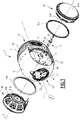
figure 1 est une vue éclatée, en perspective, d'une enceinte acoustique selon l'invention, - les
figures 2 et 3 sont des vues respectivement de côté et de face de l'enceinte acoustique représentée sur lafigure 1 , - la
figure 4 est une vue de l'enceinte acoustique représentée sur lesfigure 1 à 3 , en coupe selon un plan passant par l'axe longitudinal défini par l'enceinte acoustique et par l'axe transversal défini par le haut-parleur, - la
figure 5 est une vue de face d'un insert métallique présent en deux exemplaires dans la coque de l'enceinte acoustique représentée sur lesfigures 1 à 4 , - les
figures 6 et 7 sont des vues de détail de lafigure 4 , et sont respectivement centrées sur une zone de collage d'un des haut-parleurs, et sur un joint d'étanchéité d'un de ces haut-parleurs, - la
figure 8 est une vue éclatée, en perspective, d'une enceinte acoustique constituant une variante de l'enceinte acoustique représentée sur lesfigures 1 à 4 , - la
figure 9 est une vue de l'enceinte acoustique représentée sur lafigure 8 , en coupe selon un plan médian vertical, et - la
figure 10 est une vue de détail de l'enceinte acoustique représentée sur lesfigures 8 et9 , en coupe selon un plan perpendiculaire à l'axe longitudinal et passant par l'axe transversal défini par les haut-parleurs. - En référence aux
figures 1 à 4 , on décrit une enceinte acoustique 1 selon l'invention. - L'enceinte acoustique 1 est par exemple une enceinte active, c'est-à-dire qu'elle comporte notamment un lecteur de signaux audio et un amplificateur (non représentés). De même, par souci de clarté, d'autres éléments électriques ou électroniques de l'enceinte acoustique non directement liés à l'invention ne sont pas représentés sur les figures.
- L'enceinte acoustique 1 comprend une armature 3 métallique, et une coque 5 en matière plastique fixée sur l'armature et définissant au moins deux ouvertures 7A, 7B. L'enceinte acoustique 1 comprend deux haut-parleurs 9A, 9B disposés tête- bêche selon un axe transversal T et s'étendant respectivement en travers des deux ouvertures 7A, 7B. L'enceinte acoustique comprend un système de fixation 11 adapté pour fixer le haut-parleur 9B sur l'armature 3, le haut-parleur 9A étant, dans l'exemple représenté, fixé d'une manière plus simple sur cette armature.
- L'axe transversal T est par exemple horizontal lorsque l'enceinte acoustique est en position d'utilisation sur une surface horizontale S.
- Dans l'exemple représenté, l'enceinte acoustique 1 est oblongue selon un axe longitudinal L avantageusement perpendiculaire à l'axe transversal T. Ainsi, l'enceinte acoustique 1 comporte une partie avant 13 formée par la coque 5, et une partie arrière 15 formée par l'armature 3.
- Avantageusement, l'enceinte acoustique 1 comprend un troisième haut-parleur (non représenté) fixé dans un logement 17 défini par la coque 5.
- L'enceinte acoustique présente par exemple une forme extérieure symétrique par rapport à un plan P perpendiculaire à l'axe transversal T et passant par l'axe longitudinal L.
- L'armature 3 est par exemple une pièce de fonderie, avantageusement en aluminium.
- L'armature 3 comprend une partie externe 19 formant la partie arrière 15 de l'enceinte acoustique et adaptée pour s'emboîter avec la coque 5, par exemple selon l'axe longitudinal L. L'armature 3 comprend aussi une partie interne 21 s'étendant entre les deux haut-parleurs 9A, 9B selon le plan P et sur laquelle les deux haut-parleurs sont rigidement fixés.
- Par « rigidement fixé », on entend ici une fixation mécanique solide, par ailleurs résistant, par exemple, à une force d'arrachement de 100 N (newton), de préférence 1000 N.
- La partie externe 19 comprend une portion arrière 23 (
figure 4 ) définissant une pluralité d'ailettes 25 pour évacuer la chaleur générée à l'intérieur de l'enceinte acoustique, et une semelle 27 s'étendent longitudinalement sous les haut-parleurs 9A, 9B à partir de la portion arrière 23. - La partie interne 21 présente par exemple une forme générale plane. La partie interne 21 est avantageusement venue de matière la portion arrière 23 et la semelle 27. La partie interne 21 définit un passage 29 axial traversé par le système de fixation 11.
- Sur une première face 31A transversalement orientée vers le haut-parleur 9A, la partie interne définit une surface de réception 33A du haut-parleur 9A. Sur une deuxième face 31B transversalement orientée vers le haut-parleur 9B, la partie interne définit une surface de réception 33B du haut-parleur 98.
- Les surfaces de réception 33A, 33B sont avantageusement perpendiculaires à l'axe transversal T. Les surfaces de réception entourent avantageusement complètement l'axe transversal T et présentent par exemple une forme annulaire. Les surfaces de réception forment des protubérances transversales de la partie interne 21, respectivement sur la première face 31A et sur la deuxième face 31B.
- La coque 5 est avantageusement monobloc. Par « monobloc », on entend que la coque est d'un seul tenant et n'est pas constituée de portions mécaniquement fixées les unes sur les autres.
- La coque 5 définit avec la partie externe 19 de l'armature un volume interne 35 de l'enceinte acoustique dans lequel les haut-parleurs 9A et 9B sont en grande partie insérés.
- La coque 5 comprend une couche interne 37 comprenant par exemple du polycarbonate (PC) et entre 15% et 25% en masse de fibres de verre, et une couche externe 39, ou couche de finition, comportant par exemple de l'acrylonitrile butadiène styrène (ABS).
- La coque est fixée rigidement sur la partie interne 21 de l'armature, par exemple à l'aide d'un goujon 41 vissé longitudinalement dans la tranche de la partie interne 21, et d'un écrou 43 vissé sur le goujon pour presser la coque longitudinalement contre la partie interne.
- La coque n'est pas rigidement liée aux deux haut-parleurs 9A, 9B autrement que par l'intermédiaire de l'armature 3. La coque est adaptée pour permettre une insertion des haut-parleurs 9A, 9B selon l'axe transversal T respectivement par les ouvertures 7A, 7B jusqu'à la partie interne 21 de l'armature.
- La coque comprend deux parois postérieures 45A, 45B respectivement situées longitudinalement entre les haut-parleurs 9A, 9B et la portion arrière 23 de l'armature.
- La coque définit avantageusement une ouverture 46 pour accéder au haut-parleur 9A.
- L'ouverture 46 est avantageusement située dans le logement 17 et cachée par le troisième haut-parleur (non-représenté).
- La couche interne 37 délimite le volume interne 35.
- Les ouvertures 7A, 7B sont avantageusement circulaires et par exemple centrées sur l'axe transversal T. Les ouvertures 7A, 7B sont délimitées respectivement par deux bords 47A, 47B de la coque.
- Le bord 47A et la paroi postérieure 45A sont rigidifiés par un insert 49A métallique.
- Le bord 49B et la paroi postérieure 45B sont rigidifiés par un insert 49B métallique avantageusement analogue structurellement à l'insert métallique 49A.
- Les deux inserts étant structurellement analogues, seul l'insert 49A sera brièvement décrit en référence à la
figure 5 . - L'insert 49A est surmoulé par la couche interne 37 de la coque. L'insert métallique 49A comprend une partie circulaire 51 située dans le bord 47A pour rigidifier ce dernier, et une partie 53 adjacente longitudinalement à la partie circulaire 51 et située dans la paroi postérieure 45A.
- Les haut-parleurs 9A, 9B sont par exemple des haut-parleurs de grave. Par « haut-parleur de grave », on entend par exemple un haut-parleur adapté pour diffuser des ondes sonores de fréquences inférieures à 1000 Hz, préférentiellement inférieures à 500 Hz, encore plus préférentiellement inférieures à 150 Hz.
- Les haut-parleurs 9A, 9B comprennent respectivement un châssis 55A, 55B (
figure 4 ), une membrane 57A, 57B adaptée pour émettre des ondes sonores, et un circuit magnétique 59A, 59B. - Les membranes 57A, 57B sont avantageusement des calottes sphériques. Les membranes ne sont pas interrompues au niveau de l'axe transversal T, car les haut-parleurs 9A, 9B sont fixés sur la partie interne 21 par leurs côtés transversalement opposés aux membranes.
- Les circuits magnétiques 59A, 59B sont fixés sur partie interne 21 de l'armature. Les circuits magnétiques 59A, 59B définissent respectivement des surfaces 61A, 61B en contact avec les surfaces de réception 33A, 33B de l'armature. Les circuits magnétiques définissent respectivement un logement axial 63A, 63B débouchant au moins du côté de la partie interne 21 de l'armature.
- Comme visible sur la
figure 6 , la surface 61A est délimitée radialement à partir de l'axe transversal T par un rebord 65A formé par le circuit magnétique 59A. - La surface 33A est par exemple collée sur la surface de réception 61A à l'aide d'une colle 67.
- Avantageusement, le rebord 65A et la protubérance de la partie interne 21 formant la surface de réception 33A définissent ensemble un logement 69 dans lequel un trop plein de colle 67 est présent, ce qui renforce la cohésion entre le circuit magnétique 59A et la partie interne 21 de l'armature.
- Dans l'exemple, les châssis 55A, 55B sont fixés sur les circuits magnétiques 59A, 59B et ne sont pas fixés directement sur l'armature.
- Les châssis 55A, 55B ne sont pas rigidement fixés sur la coque 5 autrement que par l'intermédiaire des moteurs magnétiques et de l'armature 3. Dit autrement, les châssis des haut-parleurs 9A, 9B sont en porte-à-faux par rapport aux bords 47A, 47B de la coque.
- Comme visible sur la
figure 7 , des joints d'étanchéité 71A, 71B sont disposés respectivement entre les haut-parleurs 9A, 9B et les bords 47A, 47B de la coque. Toutefois, ces joints ne constituent pas un lien rigide entre les haut-parleurs 9A, 9B et la coque. - Les joints d'étanchéité 71A et 71B étant structurellement identiques l'un à l'autre et symétriques l'un de l'autre par rapport au plan P, seul le joint 71A sera décrit ci-après.
- Le joint 71A comprend une partie principale 73 enserrant élastiquement le châssis 55A autour de l'axe transversal T, et une lèvre 75 en appui sur le bord 47A de la coque.
- La partie principale 73 est en butée transversale contre un épaulement 77A formé par le châssis 55A.
- La lèvre 75 est fléchie transversalement du côté extérieur de l'enceinte acoustique.
- Cette configuration du joint 71A permet une introduction aisée du haut-parleur 9A dans le volume interne 35 par l'ouverture 7A.
- Le système de fixation 11 comprend une première partie 79 traversant axialement la partie interne 21 de l'armature via le passage 29, et une deuxième partie 81 située transversalement de l'autre côté de la partie interne 21 par rapport au haut-parleur 9B.
- Dans l'exemple représenté, la première partie 79 est une tige de vis, et la deuxième partie comprend une tête de cette vis et une rondelle.
- La première partie 79, c'est-à-dire la tige de vis, est vissée dans le logement 63B formé par le circuit magnétique 59B du haut-parleur 9B.
- La deuxième partie 81, c'est-à-dire la tête de vis, est montée mobile en rotation par rapport à la partie interne 21 autour d'un axe T' qui est dans l'exemple l'axe transversal T, entre une position de blocage du haut-parleur 9B, et une position de déblocage permettant d'extraire le haut-parleur 9B par l'ouverture 7B.
- Dans la position de blocage, représentée sur la
figure 4 , la partie interne 21 est prise en sandwich axialement entre le haut-parleur 9B et la deuxième partie 81. - Dans la position de déblocage, la première partie 79 est dévissée du circuit magnétique 59B, ce qui libère le haut-parleur 9B, qui peut être extrait du volume interne 35 par une translation selon l'axe transversal T.
- La deuxième partie 81, c'est-à-dire la tête de vis est actionnable en rotation autour de l'axe T' depuis le côté de la partie interne 21 opposé au haut-parleur 9B en l'absence du haut-parleur 9A.
- Dans l'exemple représenté, la deuxième partie 81 comporte un prolongement 83 transversal engagé dans le logement 63A défini par le haut-parleur 9A. Ceci permet de guider le déplacement du haut-parleur 9A lorsque celui-ci est introduit dans le volume interne 35 pour être collé sur la surface de réception 33A de l'armature.
- Selon une variante non-représentée, le système de fixation 11 comporte un goujon solidaire du haut-parleur 9B et traversant le passage 29, et un écrou vissé sur le goujon depuis le côté de la partie interne 21 transversalement opposé au haut-parleur 9B.
- Le montage de l'enceinte acoustique 1 va maintenant être brièvement décrit.
- Après avoir fixé sur l'armature des éléments électroniques non représentés, la coque 5 et l'armature 3 sont emboîtées l'une dans l'autre selon l'axe longitudinal L. La coque est alors fixée sur l'armature en vissant l'écrou 43 sur le goujon 41.
- Le haut-parleur 9B est alors introduit selon l'axe transversal T dans le volume interne 35 via l'ouverture 7B.
- Depuis l'autre côté de la partie interne 21, qui n'est pas encore occupé par le haut-parleur 9A, le système de fixation 11 est introduit dans le passage 29. La première partie 79 est vissée dans le logement 63B jusqu'à ce que la deuxième partie 81 vienne en butée contre la partie interne 21. La surface 61B du circuit magnétique 59B est alors maintenue fermement en contact avec la surface de réception 33B de la partie interne. L'opération de vissage du système de fixation 11 est facilement réalisée depuis le côté de la partie interne 21 non encore occupée par le haut-parleur 9A.
- Ensuite la surface de réception 33A et/ou la surface 61A du circuit magnétique 59A sont enduites de la colle 67. Le haut-parleur 9A est alors introduit dans le volume interne 35 via l'ouverture 7A de la coque. Le prolongement 83 de la deuxième partie 81 entre dans le logement 63A défini par le circuit magnétique 59A, ce qui permet de guider le déplacement du haut-parleur 9A. La surface 61A et la surface de réception 33A sont ensuite maintenues en contact l'une avec l'autre. Un trop plein de colle 67 s'écoule dans le logement 69. Le séchage s'opère. Le haut-parleur 9A est à son tour solidement fixé sur la partie interne 21 de l'armature.
- Pour un démontage éventuel des haut-parleurs, on utilise l'ouverture 46 d'accès définie par la coque pour introduire un outil adapté (non représenté) pour décoller le haut-parleur 9A de la partie interne 21. Le haut-parleur 9A peut alors être extrait selon l'axe transversal T. Une fois que le haut-parleur 9A est extrait, le système de fixation 11 devient accessible par l'ouverture 7A. Il est alors possible d'agir sur la deuxième partie 81 en rotation pour dévisser la première partie 79 et libérer le haut-parleur 9B. Le haut-parleur 9B peut alors être extrait selon l'axe transversal T par l'ouverture 7B.
- Grâce aux caractéristiques décrites ci-dessus, l'enceinte acoustique 1 est aisée à assembler et à désassembler, malgré le caractère monobloc de sa coque 5.
- En référence aux
figures 8 à 10 , on va maintenant décrire une enceinte acoustique 100 constituant une variante de l'enceinte acoustique 1. L'enceinte acoustique 100 est analogue à l'enceinte acoustique 1 représentée sur lesfigures 1 à 7 . Les éléments similaires portent les mêmes références numériques qui ne seront pas décrits à nouveau. Seules les différences notables seront décrites ci-après. - L'enceinte acoustique 100 diffère par le mode de fixation des haut-parleurs 9A, 9B.
- Le haut-parleur 9A de l'enceinte acoustique 100 est fixé par vissage de manière analogue au haut-parleur 9B de l'enceinte acoustique 1. Comme visible sur la
figure 10 , le système de fixation 11 fixe rigidement le haut-parleur 9A sur la partie interne 21. La première partie 79 est vissée dans le circuit magnétique 59A, et la deuxième partie 81 permet de visser la première partie depuis le côté de la partie interne 21 opposé au haut-parleur 9A. - La deuxième partie 81 est dépourvue du prolongement 83 présent dans l'enceinte acoustique 1.
- Le haut-parleur 9B est fixé sur la partie interne 21 par un système de fixation 111 qui ne fait pas intervenir un collage du haut-parleur 9B sur la partie interne 21.
- Le système de fixation 111 comprend deux goupilles 113, 115 permettant de bloquer ou de débloquer le haut-parleur 9B par rapport à la partie interne 21.
- Selon une variante non représentée, le système de fixation 111 est configuré pour ne comporter qu'une seule goupille.
- Le système de fixation 111 comprend un bloc support 117 pour guider longitudinalement les goupilles 113, 115, une vis épaulée 119 vissée axialement dans le circuit magnétique 59B du haut-parleur 9B, une rondelle ressort 121, et une pièce de liaison 123 enfilées sur la vis épaulée 119.
- La rondelle ressort 121 est comprimée transversalement entre la pièce de liaison 123 et une tête 125 de la vis épaulée 119. La rondelle ressort 121 présente une raideur élevée.
- En variante (non représentée), plusieurs rondelles ressort sont disposées en série entre la pièce de liaison 123 et la tête 125.
- Le bloc support 117 est fixé sur la partie interne 21 de l'armature du côté du haut-parleur 9B, par exemple par des vis. Le bloc support définit deux passages 127, 129 longitudinaux pour les goupilles 113, 115, et un logement 131 dans lequel se trouvent la tête de vis 125, la rondelle ressort 121 et la pièce de liaison 123.
- Les goupilles 113, 115 présentent par exemple un profil fuselé avec un diamètre croissant progressivement dans le sens longitudinal vers leurs têtes 133 à 135 afin de comprimer progressivement les rondelles ressorts 121 et de faciliter l'assemblage du système.
- La pièce de liaison 123 comporte un rebord 137 formant une butée transversale pour les goupilles 113, 115.
- Lorsque les goupilles 113, 115 sont vissées dans le bloc support 117, les goupilles poussent la pièce de liaison 123 selon l'axe transversal T vers la partie interne 21 de l'armature, ce qui a pour effet de comprimer davantage la rondelle ressort 121 entre la tête de vis 125 et la pièce de liaison 123. Ainsi, la force élastique appliquée par la rondelle ressort 121 sur la tête de vis 125 maintient fermement le circuit magnétique 59B contre le bloc support 117, réalisant ainsi la fixation du haut-parleur 9B sur la partie interne 21.
- Le haut-parleur 9B est rigidement fixé sur la partie interne 21, au sens où une force d'arrachement doit vaincre la raideur de la rondelle ressort 121 pour éloigner le circuit magnétique 59B du bloc support 117. De plus, le haut-parleur 9B est ramené vers le bloc support dès que cette force cesse.
- En variante, les goupilles 113, 115 sont vissées dans la partie interne 21 de l'armature, et le bloc support 117 est avantageusement supprimé.
- Avantageusement, la coque 5 définit deux ouvertures 139, 141 pour accéder aux têtes 133, 135 des goupilles depuis l'extérieur de la coque.
- Ces ouvertures d'accès sont avantageusement masquées par le troisième haut-parleur.
Claims (9)
- Enceinte acoustique (1 ; 100) comprenant :- une armature (3), et une coque (5) sur l'armature (3), la coque (5) définissant au moins deux ouvertures (7A, 7B), et- au moins deux haut-parleurs (9A, 9B) disposés tête-bêche selon un axe transversal (T), les deux haut-parleurs (9A, 9B) s'étendant respectivement en travers des deux ouvertures (7A, 7B),l'armature (3) comprenant une partie interne (21) située transversalement entre les deux haut-parleurs (9A, 9B) et sur laquelle les deux haut-parleurs (9A, 9B) sont fixés,
caractérisée en ce que :- l'armature (3) est métallique et la coque (5) est en matière plastique, et- les deux haut-parleurs (9A, 9B) sont dépourvus de toute liaison rigide avec la coque (5) autre que celle formée par l'armature (3). - Enceinte acoustique (1 ; 100) selon la revendication 1, dans laquelle la coque (5) est monobloc.
- Enceinte acoustique (1 ; 100) selon la revendication 1 ou 2, dans laquelle :- l'armature (3) comprend une partie externe (19) formant une partie arrière (15) de l'enceinte acoustique (1 ; 100) selon un axe longitudinal (L), la coque (5) formant une partie avant (13) de l'enceinte acoustique (1 ; 100) selon l'axe longitudinal (L), et- la coque (5) et la partie externe (19) de l'armature (3) sont adaptées pour s'emboîter l'une dans l'autre selon l'axe longitudinal (L).
- Enceinte acoustique (1) selon l'une quelconque des revendications 1 à 3, comprenant un système de fixation (11) adapté pour fixer l'un (9B) des deux haut-parleurs (9A, 9B) sur la partie interne (21), le premier système de fixation (11) comportant :- une première partie (79) traversant la partie interne (21) de l'armature (3), et- une deuxième partie (81) située transversalement de l'autre côté de la partie interne (21) par rapport audit un (9B) des deux haut-parleurs (9A, 9B), la deuxième partie (81) étant montée mobile en rotation par rapport à la partie interne (21) autour d'un axe (T') parallèle à l'axe transversal (T) entre une position de blocage, dans laquelle la partie interne (21) est prise en sandwich entre ledit un (9B) des deux haut-parleurs (9A, 9B) et la deuxième partie (81), et une position de déblocage permettant d'extraire ledit un (9B) des deux haut-parleurs (9A, 9B) par l'une des deux ouvertures (7A, 7B), la deuxième partie (81) étant actionnable en rotation depuis ledit autre côté de la partie interne (21) en l'absence de l'autre (9A) des deux haut-parleurs (9A, 9B).
- Enceinte acoustique (1) selon la revendication 4, dans laquelle la première partie (79) du système de fixation (11) comprend une tige d'une vis, et la deuxième partie (81) comprend une tête de cette vis.
- Enceinte acoustique (1) selon la revendication 4 ou 5, dans laquelle la deuxième partie (81) du système de fixation (11) comporte un prolongement (83) selon l'axe transversal (T) engagé dans un logement (63A) défini par l'autre (9A) des deux haut-parleurs (9A, 9B).
- Enceinte acoustique (1) selon l'une quelconque des revendications 1 à 6, dans laquelle au moins l'un (9A) des haut-parleurs (9A, 9B) comprend une surface (61A) collée sur la partie interne (21) de l'armature (3).
- Enceinte acoustique (1) selon la revendication 7, dans laquelle la coque (5) définit une ouverture (46) formant un accès à la surface (61A) collée.
- Enceinte acoustique (100) selon l'une quelconque des revendications 1 à 8, dans laquelle l'un (9B) des deux haut-parleurs (9A, 9B) est fixé sur la partie interne (21) de l'armature (3) par un système de fixation (111) comprenant au moins une goupille (113, 115) orientée perpendiculairement à l'axe transversal (T) et comportant une tête (9B) accessible par au moins une ouverture (139, 141) de la coque (5) pour déplacer la goupille (113, 115) par rapport à la partie interne (21) de l'armature (3) entre une position de blocage dudit un (9B) des deux haut-parleurs (9A, 9B), et une position de déblocage permettant d'extraire ledit un (9B) des deux haut-parleurs (9A, 9B) par l'une (7B) des deux ouvertures (7A, 7B).
Applications Claiming Priority (1)
| Application Number | Priority Date | Filing Date | Title |
|---|---|---|---|
| FR1859308A FR3087067B1 (fr) | 2018-10-08 | 2018-10-08 | Enceinte acoustique a deux haut-parleurs tete-beche fixes sur une armature interne |
Publications (2)
| Publication Number | Publication Date |
|---|---|
| EP3637790A1 EP3637790A1 (fr) | 2020-04-15 |
| EP3637790B1 true EP3637790B1 (fr) | 2022-04-20 |
Family
ID=65244180
Family Applications (1)
| Application Number | Title | Priority Date | Filing Date |
|---|---|---|---|
| EP19201132.8A Active EP3637790B1 (fr) | 2018-10-08 | 2019-10-02 | Enceinte acoustique à deux haut-parleurs dos à dos fixés sur une armature interne |
Country Status (5)
| Country | Link |
|---|---|
| US (1) | US10834488B2 (fr) |
| EP (1) | EP3637790B1 (fr) |
| JP (1) | JP7576908B2 (fr) |
| CN (1) | CN111010630B (fr) |
| FR (1) | FR3087067B1 (fr) |
Families Citing this family (6)
| Publication number | Priority date | Publication date | Assignee | Title |
|---|---|---|---|---|
| USD717341S1 (en) * | 2013-06-09 | 2014-11-11 | Apple Inc. | Electronic device |
| WO2022067018A1 (fr) * | 2020-09-25 | 2022-03-31 | Sterling Labs Llc. | Système à double haut-parleur |
| FR3124633B1 (fr) * | 2021-06-28 | 2024-02-02 | Devialet | Système acoustique comprenant un système de démontage avec résistance électrique chauffante. |
| FR3137522B1 (fr) | 2022-07-04 | 2025-03-07 | Devialet | Enceinte acoustique à haut-parleur tête bêche |
| FR3165138A1 (fr) | 2024-07-23 | 2026-01-30 | Devialet | Enceinte acoustique à deux haut-parleurs tête-bêche radialement fixés sur une âme centrale |
| CN119421075B (zh) * | 2024-11-01 | 2026-02-27 | 东莞市金文华数码科技有限公司 | 一种防水同轴音箱 |
Family Cites Families (9)
| Publication number | Priority date | Publication date | Assignee | Title |
|---|---|---|---|---|
| DE3414407C2 (de) * | 1984-04-17 | 1986-02-20 | Jürgen 6804 Ilvesheim Quaas | Anordnung von Schallwandlern in einer Schallführung, insbesondere für Lautsprecherboxen |
| US4876723A (en) * | 1988-11-30 | 1989-10-24 | Peter Tsung-Hou Fei | Loudspeaker system |
| CN1112348A (zh) * | 1995-07-19 | 1995-11-22 | 高诚 | 平衡式音箱 |
| JP2001352592A (ja) * | 2000-06-08 | 2001-12-21 | Fujitsu Ten Ltd | スピーカ構造 |
| GB2414620A (en) * | 2004-05-24 | 2005-11-30 | Blast Loudspeakers Ltd | Loudspeaker with opposing drivers for vibration cancelling |
| JP3175641U (ja) * | 2012-03-02 | 2012-05-24 | 浩一 佐藤 | スピーカ装置 |
| FR3015166B1 (fr) * | 2013-12-18 | 2017-07-14 | Devialet | Enceinte acoustique comprenant une paroi externe non conductrice de la chaleur, un haut-parleur electrodynamique et un circuit electronique de commande |
| RU146313U1 (ru) * | 2014-01-31 | 2014-10-10 | Федеральное государственное бюджетное образовательное учреждение высшего профессионального образования "Ульяновский государственный технический университет" | Динамический громкоговоритель |
| CN205610891U (zh) * | 2016-03-17 | 2016-09-28 | 乐视致新电子科技(天津)有限公司 | 一种扬声器装置及音箱系统 |
-
2018
- 2018-10-08 FR FR1859308A patent/FR3087067B1/fr active Active
-
2019
- 2019-10-02 EP EP19201132.8A patent/EP3637790B1/fr active Active
- 2019-10-07 JP JP2019184517A patent/JP7576908B2/ja active Active
- 2019-10-07 US US16/594,970 patent/US10834488B2/en active Active
- 2019-10-08 CN CN201910949303.0A patent/CN111010630B/zh active Active
Also Published As
| Publication number | Publication date |
|---|---|
| CN111010630B (zh) | 2024-06-25 |
| JP7576908B2 (ja) | 2024-11-01 |
| FR3087067B1 (fr) | 2022-02-25 |
| CN111010630A (zh) | 2020-04-14 |
| FR3087067A1 (fr) | 2020-04-10 |
| EP3637790A1 (fr) | 2020-04-15 |
| JP2020065250A (ja) | 2020-04-23 |
| US20200112778A1 (en) | 2020-04-09 |
| US10834488B2 (en) | 2020-11-10 |
Similar Documents
| Publication | Publication Date | Title |
|---|---|---|
| EP3637790A1 (fr) | Enceinte acoustique à deux haut-parleurs dos à dos fixés sur une armature interne | |
| EP2874022B1 (fr) | Boîte de montre comprenant une liaison à baïonnette | |
| EP0053543A2 (fr) | Perfectionnements aux dispositifs pour fixer des objets sur des tôles accessibles d'un seul côté | |
| EP3540523B1 (fr) | Montre comprenant une boite de montre munie de deux cadrans | |
| EP3222876B1 (fr) | Dispositif d'amortissement pendulaire | |
| EP3637787B1 (fr) | Enceinte acoustique comportant une coque en matière plastique monobloc | |
| EP4113506B1 (fr) | Enceinte acoustique comprenant un caisson et un haut-parleur monté rotatif | |
| FR2737267A1 (fr) | Friction d'embrayage, notamment pour vehicule automobile | |
| WO2010052003A1 (fr) | Module mecanique pour une cle d'un vehicule et procede de fabrication | |
| EP1026356B1 (fr) | Panneau formé d'une plaque en verre, muni d'au moins un dispositif d'assemblage à une structure voisine | |
| EP4125085B1 (fr) | Haut-parleur comprenant une membrane montée réversiblement, et enceinte acoustique intégrant un tel haut-parleur | |
| EP0119361B1 (fr) | Profilé d'encadrement pour survitrage ouvrant | |
| EP4576814B1 (fr) | Enceinte compacte a conception externe modulaire | |
| FR3097397A1 (fr) | Enceinte acoustique simplifiée | |
| FR3009042A1 (fr) | Ensemble de montage pour la fabrication des ceintures de tiroirs | |
| FR3153210A1 (fr) | Enceinte acoustique a joues laterales interchangeables | |
| FR2533853A1 (fr) | Ponceuse mecanique portative dite " ponceuse vibrante " | |
| EP3637791B1 (fr) | Enceinte acoustique comportant une coque en matière plastique | |
| FR2886614A1 (fr) | Joint peripherique d'un vitrage d'optique d'un vehicule automobile | |
| FR2506405A1 (fr) | Element d'assemblage et procede et outil de montage d'un tel element | |
| WO2026022145A1 (fr) | Enceinte acoustique à deux haut-parleurs tête-bêche radialement fixés sur une âme centrale | |
| FR2742510A1 (fr) | Volant amortisseur, notamment pour vehicule automobile | |
| FR2677465A1 (fr) | Monture de lunettes. | |
| WO2021037570A1 (fr) | Kit pour l'élaboration d'un ensemble autoportant de serrure électronique | |
| FR3010943A1 (fr) | Porte a chambre acoustique structurante |
Legal Events
| Date | Code | Title | Description |
|---|---|---|---|
| PUAI | Public reference made under article 153(3) epc to a published international application that has entered the european phase |
Free format text: ORIGINAL CODE: 0009012 |
|
| STAA | Information on the status of an ep patent application or granted ep patent |
Free format text: STATUS: THE APPLICATION HAS BEEN PUBLISHED |
|
| AK | Designated contracting states |
Kind code of ref document: A1 Designated state(s): AL AT BE BG CH CY CZ DE DK EE ES FI FR GB GR HR HU IE IS IT LI LT LU LV MC MK MT NL NO PL PT RO RS SE SI SK SM TR |
|
| AX | Request for extension of the european patent |
Extension state: BA ME |
|
| STAA | Information on the status of an ep patent application or granted ep patent |
Free format text: STATUS: REQUEST FOR EXAMINATION WAS MADE |
|
| 17P | Request for examination filed |
Effective date: 20200917 |
|
| RBV | Designated contracting states (corrected) |
Designated state(s): AL AT BE BG CH CY CZ DE DK EE ES FI FR GB GR HR HU IE IS IT LI LT LU LV MC MK MT NL NO PL PT RO RS SE SI SK SM TR |
|
| RIC1 | Information provided on ipc code assigned before grant |
Ipc: H04R 9/02 20060101ALN20211007BHEP Ipc: H04R 5/02 20060101ALN20211007BHEP Ipc: H04R 1/02 20060101ALN20211007BHEP Ipc: H04R 1/28 20060101AFI20211007BHEP |
|
| GRAP | Despatch of communication of intention to grant a patent |
Free format text: ORIGINAL CODE: EPIDOSNIGR1 |
|
| STAA | Information on the status of an ep patent application or granted ep patent |
Free format text: STATUS: GRANT OF PATENT IS INTENDED |
|
| INTG | Intention to grant announced |
Effective date: 20211116 |
|
| GRAS | Grant fee paid |
Free format text: ORIGINAL CODE: EPIDOSNIGR3 |
|
| GRAA | (expected) grant |
Free format text: ORIGINAL CODE: 0009210 |
|
| STAA | Information on the status of an ep patent application or granted ep patent |
Free format text: STATUS: THE PATENT HAS BEEN GRANTED |
|
| AK | Designated contracting states |
Kind code of ref document: B1 Designated state(s): AL AT BE BG CH CY CZ DE DK EE ES FI FR GB GR HR HU IE IS IT LI LT LU LV MC MK MT NL NO PL PT RO RS SE SI SK SM TR |
|
| REG | Reference to a national code |
Ref country code: GB Ref legal event code: FG4D Free format text: NOT ENGLISH |
|
| REG | Reference to a national code |
Ref country code: CH Ref legal event code: EP |
|
| REG | Reference to a national code |
Ref country code: IE Ref legal event code: FG4D Free format text: LANGUAGE OF EP DOCUMENT: FRENCH |
|
| REG | Reference to a national code |
Ref country code: DE Ref legal event code: R096 Ref document number: 602019013860 Country of ref document: DE |
|
| REG | Reference to a national code |
Ref country code: AT Ref legal event code: REF Ref document number: 1486103 Country of ref document: AT Kind code of ref document: T Effective date: 20220515 |
|
| REG | Reference to a national code |
Ref country code: LT Ref legal event code: MG9D |
|
| REG | Reference to a national code |
Ref country code: NL Ref legal event code: MP Effective date: 20220420 |
|
| REG | Reference to a national code |
Ref country code: AT Ref legal event code: MK05 Ref document number: 1486103 Country of ref document: AT Kind code of ref document: T Effective date: 20220420 |
|
| PG25 | Lapsed in a contracting state [announced via postgrant information from national office to epo] |
Ref country code: NL Free format text: LAPSE BECAUSE OF FAILURE TO SUBMIT A TRANSLATION OF THE DESCRIPTION OR TO PAY THE FEE WITHIN THE PRESCRIBED TIME-LIMIT Effective date: 20220420 |
|
| PG25 | Lapsed in a contracting state [announced via postgrant information from national office to epo] |
Ref country code: SE Free format text: LAPSE BECAUSE OF FAILURE TO SUBMIT A TRANSLATION OF THE DESCRIPTION OR TO PAY THE FEE WITHIN THE PRESCRIBED TIME-LIMIT Effective date: 20220420 Ref country code: PT Free format text: LAPSE BECAUSE OF FAILURE TO SUBMIT A TRANSLATION OF THE DESCRIPTION OR TO PAY THE FEE WITHIN THE PRESCRIBED TIME-LIMIT Effective date: 20220822 Ref country code: NO Free format text: LAPSE BECAUSE OF FAILURE TO SUBMIT A TRANSLATION OF THE DESCRIPTION OR TO PAY THE FEE WITHIN THE PRESCRIBED TIME-LIMIT Effective date: 20220720 Ref country code: LT Free format text: LAPSE BECAUSE OF FAILURE TO SUBMIT A TRANSLATION OF THE DESCRIPTION OR TO PAY THE FEE WITHIN THE PRESCRIBED TIME-LIMIT Effective date: 20220420 Ref country code: HR Free format text: LAPSE BECAUSE OF FAILURE TO SUBMIT A TRANSLATION OF THE DESCRIPTION OR TO PAY THE FEE WITHIN THE PRESCRIBED TIME-LIMIT Effective date: 20220420 Ref country code: GR Free format text: LAPSE BECAUSE OF FAILURE TO SUBMIT A TRANSLATION OF THE DESCRIPTION OR TO PAY THE FEE WITHIN THE PRESCRIBED TIME-LIMIT Effective date: 20220721 Ref country code: FI Free format text: LAPSE BECAUSE OF FAILURE TO SUBMIT A TRANSLATION OF THE DESCRIPTION OR TO PAY THE FEE WITHIN THE PRESCRIBED TIME-LIMIT Effective date: 20220420 Ref country code: ES Free format text: LAPSE BECAUSE OF FAILURE TO SUBMIT A TRANSLATION OF THE DESCRIPTION OR TO PAY THE FEE WITHIN THE PRESCRIBED TIME-LIMIT Effective date: 20220420 Ref country code: BG Free format text: LAPSE BECAUSE OF FAILURE TO SUBMIT A TRANSLATION OF THE DESCRIPTION OR TO PAY THE FEE WITHIN THE PRESCRIBED TIME-LIMIT Effective date: 20220720 Ref country code: AT Free format text: LAPSE BECAUSE OF FAILURE TO SUBMIT A TRANSLATION OF THE DESCRIPTION OR TO PAY THE FEE WITHIN THE PRESCRIBED TIME-LIMIT Effective date: 20220420 |
|
| PG25 | Lapsed in a contracting state [announced via postgrant information from national office to epo] |
Ref country code: RS Free format text: LAPSE BECAUSE OF FAILURE TO SUBMIT A TRANSLATION OF THE DESCRIPTION OR TO PAY THE FEE WITHIN THE PRESCRIBED TIME-LIMIT Effective date: 20220420 Ref country code: PL Free format text: LAPSE BECAUSE OF FAILURE TO SUBMIT A TRANSLATION OF THE DESCRIPTION OR TO PAY THE FEE WITHIN THE PRESCRIBED TIME-LIMIT Effective date: 20220420 Ref country code: LV Free format text: LAPSE BECAUSE OF FAILURE TO SUBMIT A TRANSLATION OF THE DESCRIPTION OR TO PAY THE FEE WITHIN THE PRESCRIBED TIME-LIMIT Effective date: 20220420 Ref country code: IS Free format text: LAPSE BECAUSE OF FAILURE TO SUBMIT A TRANSLATION OF THE DESCRIPTION OR TO PAY THE FEE WITHIN THE PRESCRIBED TIME-LIMIT Effective date: 20220820 |
|
| REG | Reference to a national code |
Ref country code: DE Ref legal event code: R097 Ref document number: 602019013860 Country of ref document: DE |
|
| PG25 | Lapsed in a contracting state [announced via postgrant information from national office to epo] |
Ref country code: SM Free format text: LAPSE BECAUSE OF FAILURE TO SUBMIT A TRANSLATION OF THE DESCRIPTION OR TO PAY THE FEE WITHIN THE PRESCRIBED TIME-LIMIT Effective date: 20220420 Ref country code: SK Free format text: LAPSE BECAUSE OF FAILURE TO SUBMIT A TRANSLATION OF THE DESCRIPTION OR TO PAY THE FEE WITHIN THE PRESCRIBED TIME-LIMIT Effective date: 20220420 Ref country code: RO Free format text: LAPSE BECAUSE OF FAILURE TO SUBMIT A TRANSLATION OF THE DESCRIPTION OR TO PAY THE FEE WITHIN THE PRESCRIBED TIME-LIMIT Effective date: 20220420 Ref country code: EE Free format text: LAPSE BECAUSE OF FAILURE TO SUBMIT A TRANSLATION OF THE DESCRIPTION OR TO PAY THE FEE WITHIN THE PRESCRIBED TIME-LIMIT Effective date: 20220420 Ref country code: DK Free format text: LAPSE BECAUSE OF FAILURE TO SUBMIT A TRANSLATION OF THE DESCRIPTION OR TO PAY THE FEE WITHIN THE PRESCRIBED TIME-LIMIT Effective date: 20220420 Ref country code: CZ Free format text: LAPSE BECAUSE OF FAILURE TO SUBMIT A TRANSLATION OF THE DESCRIPTION OR TO PAY THE FEE WITHIN THE PRESCRIBED TIME-LIMIT Effective date: 20220420 |
|
| PLBE | No opposition filed within time limit |
Free format text: ORIGINAL CODE: 0009261 |
|
| STAA | Information on the status of an ep patent application or granted ep patent |
Free format text: STATUS: NO OPPOSITION FILED WITHIN TIME LIMIT |
|
| 26N | No opposition filed |
Effective date: 20230123 |
|
| PG25 | Lapsed in a contracting state [announced via postgrant information from national office to epo] |
Ref country code: AL Free format text: LAPSE BECAUSE OF FAILURE TO SUBMIT A TRANSLATION OF THE DESCRIPTION OR TO PAY THE FEE WITHIN THE PRESCRIBED TIME-LIMIT Effective date: 20220420 |
|
| PG25 | Lapsed in a contracting state [announced via postgrant information from national office to epo] |
Ref country code: SI Free format text: LAPSE BECAUSE OF FAILURE TO SUBMIT A TRANSLATION OF THE DESCRIPTION OR TO PAY THE FEE WITHIN THE PRESCRIBED TIME-LIMIT Effective date: 20220420 Ref country code: MC Free format text: LAPSE BECAUSE OF FAILURE TO SUBMIT A TRANSLATION OF THE DESCRIPTION OR TO PAY THE FEE WITHIN THE PRESCRIBED TIME-LIMIT Effective date: 20220420 |
|
| REG | Reference to a national code |
Ref country code: CH Ref legal event code: PL |
|
| P01 | Opt-out of the competence of the unified patent court (upc) registered |
Effective date: 20230425 |
|
| REG | Reference to a national code |
Ref country code: BE Ref legal event code: MM Effective date: 20221031 |
|
| PG25 | Lapsed in a contracting state [announced via postgrant information from national office to epo] |
Ref country code: LU Free format text: LAPSE BECAUSE OF NON-PAYMENT OF DUE FEES Effective date: 20221002 |
|
| PG25 | Lapsed in a contracting state [announced via postgrant information from national office to epo] |
Ref country code: LI Free format text: LAPSE BECAUSE OF NON-PAYMENT OF DUE FEES Effective date: 20221031 Ref country code: CH Free format text: LAPSE BECAUSE OF NON-PAYMENT OF DUE FEES Effective date: 20221031 |
|
| PG25 | Lapsed in a contracting state [announced via postgrant information from national office to epo] |
Ref country code: BE Free format text: LAPSE BECAUSE OF NON-PAYMENT OF DUE FEES Effective date: 20221031 |
|
| PG25 | Lapsed in a contracting state [announced via postgrant information from national office to epo] |
Ref country code: IE Free format text: LAPSE BECAUSE OF NON-PAYMENT OF DUE FEES Effective date: 20221002 |
|
| PG25 | Lapsed in a contracting state [announced via postgrant information from national office to epo] |
Ref country code: IT Free format text: LAPSE BECAUSE OF FAILURE TO SUBMIT A TRANSLATION OF THE DESCRIPTION OR TO PAY THE FEE WITHIN THE PRESCRIBED TIME-LIMIT Effective date: 20220420 |
|
| PG25 | Lapsed in a contracting state [announced via postgrant information from national office to epo] |
Ref country code: HU Free format text: LAPSE BECAUSE OF FAILURE TO SUBMIT A TRANSLATION OF THE DESCRIPTION OR TO PAY THE FEE WITHIN THE PRESCRIBED TIME-LIMIT; INVALID AB INITIO Effective date: 20191002 |
|
| PG25 | Lapsed in a contracting state [announced via postgrant information from national office to epo] |
Ref country code: CY Free format text: LAPSE BECAUSE OF FAILURE TO SUBMIT A TRANSLATION OF THE DESCRIPTION OR TO PAY THE FEE WITHIN THE PRESCRIBED TIME-LIMIT Effective date: 20220420 |
|
| PG25 | Lapsed in a contracting state [announced via postgrant information from national office to epo] |
Ref country code: MK Free format text: LAPSE BECAUSE OF FAILURE TO SUBMIT A TRANSLATION OF THE DESCRIPTION OR TO PAY THE FEE WITHIN THE PRESCRIBED TIME-LIMIT Effective date: 20220420 |
|
| GBPC | Gb: european patent ceased through non-payment of renewal fee |
Effective date: 20231002 |
|
| PG25 | Lapsed in a contracting state [announced via postgrant information from national office to epo] |
Ref country code: GB Free format text: LAPSE BECAUSE OF NON-PAYMENT OF DUE FEES Effective date: 20231002 |
|
| PG25 | Lapsed in a contracting state [announced via postgrant information from national office to epo] |
Ref country code: GB Free format text: LAPSE BECAUSE OF NON-PAYMENT OF DUE FEES Effective date: 20231002 |
|
| PG25 | Lapsed in a contracting state [announced via postgrant information from national office to epo] |
Ref country code: MT Free format text: LAPSE BECAUSE OF FAILURE TO SUBMIT A TRANSLATION OF THE DESCRIPTION OR TO PAY THE FEE WITHIN THE PRESCRIBED TIME-LIMIT Effective date: 20220420 |
|
| PG25 | Lapsed in a contracting state [announced via postgrant information from national office to epo] |
Ref country code: BG Free format text: LAPSE BECAUSE OF FAILURE TO SUBMIT A TRANSLATION OF THE DESCRIPTION OR TO PAY THE FEE WITHIN THE PRESCRIBED TIME-LIMIT Effective date: 20220420 |
|
| PG25 | Lapsed in a contracting state [announced via postgrant information from national office to epo] |
Ref country code: BG Free format text: LAPSE BECAUSE OF FAILURE TO SUBMIT A TRANSLATION OF THE DESCRIPTION OR TO PAY THE FEE WITHIN THE PRESCRIBED TIME-LIMIT Effective date: 20220420 |
|
| PGFP | Annual fee paid to national office [announced via postgrant information from national office to epo] |
Ref country code: FR Payment date: 20250909 Year of fee payment: 7 |
|
| PG25 | Lapsed in a contracting state [announced via postgrant information from national office to epo] |
Ref country code: TR Free format text: LAPSE BECAUSE OF FAILURE TO SUBMIT A TRANSLATION OF THE DESCRIPTION OR TO PAY THE FEE WITHIN THE PRESCRIBED TIME-LIMIT Effective date: 20220420 |
|
| PGFP | Annual fee paid to national office [announced via postgrant information from national office to epo] |
Ref country code: DE Payment date: 20251015 Year of fee payment: 7 |