EP3637568B1 - Housing of electrical equipment - Google Patents
Housing of electrical equipment Download PDFInfo
- Publication number
- EP3637568B1 EP3637568B1 EP17912835.0A EP17912835A EP3637568B1 EP 3637568 B1 EP3637568 B1 EP 3637568B1 EP 17912835 A EP17912835 A EP 17912835A EP 3637568 B1 EP3637568 B1 EP 3637568B1
- Authority
- EP
- European Patent Office
- Prior art keywords
- plate
- shaped member
- holes
- ventilation portion
- shaped
- Prior art date
- Legal status (The legal status is an assumption and is not a legal conclusion. Google has not performed a legal analysis and makes no representation as to the accuracy of the status listed.)
- Active
Links
- 238000009423 ventilation Methods 0.000 claims description 66
- 230000000149 penetrating effect Effects 0.000 claims description 2
- 239000007789 gas Substances 0.000 description 102
- 238000001816 cooling Methods 0.000 description 14
- 238000005192 partition Methods 0.000 description 13
- 238000005452 bending Methods 0.000 description 9
- 239000012530 fluid Substances 0.000 description 7
- 239000011295 pitch Substances 0.000 description 6
- 229910052751 metal Inorganic materials 0.000 description 5
- 239000002184 metal Substances 0.000 description 5
- 230000008033 biological extinction Effects 0.000 description 2
- 230000007423 decrease Effects 0.000 description 2
- 238000012423 maintenance Methods 0.000 description 2
- 230000002035 prolonged effect Effects 0.000 description 2
- 230000002411 adverse Effects 0.000 description 1
- 230000032683 aging Effects 0.000 description 1
- 229910052782 aluminium Inorganic materials 0.000 description 1
- XAGFODPZIPBFFR-UHFFFAOYSA-N aluminium Chemical compound [Al] XAGFODPZIPBFFR-UHFFFAOYSA-N 0.000 description 1
- 238000003491 array Methods 0.000 description 1
- 230000002238 attenuated effect Effects 0.000 description 1
- 230000015572 biosynthetic process Effects 0.000 description 1
- 230000003247 decreasing effect Effects 0.000 description 1
- 230000006866 deterioration Effects 0.000 description 1
- 238000007599 discharging Methods 0.000 description 1
- -1 e.g. Substances 0.000 description 1
- 230000000694 effects Effects 0.000 description 1
- 230000005489 elastic deformation Effects 0.000 description 1
- 238000010891 electric arc Methods 0.000 description 1
- 238000005516 engineering process Methods 0.000 description 1
- 238000001914 filtration Methods 0.000 description 1
- 238000007689 inspection Methods 0.000 description 1
- 239000011810 insulating material Substances 0.000 description 1
- 238000002955 isolation Methods 0.000 description 1
- 239000007769 metal material Substances 0.000 description 1
- 230000002265 prevention Effects 0.000 description 1
- 230000000644 propagated effect Effects 0.000 description 1
- 230000035939 shock Effects 0.000 description 1
- 230000035882 stress Effects 0.000 description 1
Images


Classifications
-
- H—ELECTRICITY
- H02—GENERATION; CONVERSION OR DISTRIBUTION OF ELECTRIC POWER
- H02B—BOARDS, SUBSTATIONS OR SWITCHING ARRANGEMENTS FOR THE SUPPLY OR DISTRIBUTION OF ELECTRIC POWER
- H02B1/00—Frameworks, boards, panels, desks, casings; Details of substations or switching arrangements
- H02B1/56—Cooling; Ventilation
- H02B1/565—Cooling; Ventilation for cabinets
-
- H—ELECTRICITY
- H02—GENERATION; CONVERSION OR DISTRIBUTION OF ELECTRIC POWER
- H02B—BOARDS, SUBSTATIONS OR SWITCHING ARRANGEMENTS FOR THE SUPPLY OR DISTRIBUTION OF ELECTRIC POWER
- H02B13/00—Arrangement of switchgear in which switches are enclosed in, or structurally associated with, a casing, e.g. cubicle
- H02B13/02—Arrangement of switchgear in which switches are enclosed in, or structurally associated with, a casing, e.g. cubicle with metal casing
- H02B13/025—Safety arrangements, e.g. in case of excessive pressure or fire due to electrical defect
-
- H—ELECTRICITY
- H02—GENERATION; CONVERSION OR DISTRIBUTION OF ELECTRIC POWER
- H02B—BOARDS, SUBSTATIONS OR SWITCHING ARRANGEMENTS FOR THE SUPPLY OR DISTRIBUTION OF ELECTRIC POWER
- H02B1/00—Frameworks, boards, panels, desks, casings; Details of substations or switching arrangements
- H02B1/26—Casings; Parts thereof or accessories therefor
- H02B1/30—Cabinet-type casings; Parts thereof or accessories therefor
- H02B1/32—Mounting of devices therein
- H02B1/34—Racks
- H02B1/36—Racks with withdrawable units
Definitions
- the present invention relates to an electrical equipment housing in which electrical equipment such as a circuit breaker is stored.
- a plate-shaped member having through holes is provided at an intake portion for ventilation.
- the through holes formed in the plate-shaped member allow discharge of the high-temperature high-pressure gas.
- fluid energy loss of fluid moving in the discharge direction is set to be greater than fluid energy loss of fluid moving in the intake direction.
- the parts defining the through holes in the plate-shaped member are formed such that the shape coefficient for fluid energy loss in the discharge direction is greater than the shape coefficient for energy loss in the intake direction.
- Document CN 1 312 711 C states an arc-suppressing chamber with a gas extinction device including an arc isolation wall containing multiple arc extinction gratin plates in it characterizing in setting at least two-layers of porous screens near the exit of the chamber, holes opened on the two adjacent screens arc staggered, multiple round free-erasing posts arc set between adjacent two screens above the holes of the screen inside the adjacent internal layers expressed in an arc face with the hole contact face.
- the ionized gas passes through the porous screens and free-erasing posts layer by layer alternately to be cooled effectively. The diameter of the hole is different.
- Document EP 2 145 365 A1 states a partition apparatus for an electrical power distributor unit, having partition means for placing behind a casing part, which is provided with ventilation openings, of the electrical power distributor unit, in particular a switch panel door, wherein the partition means are designed such that, in normal operating conditions, they ensure an air flow through the ventilation openings in the interior of the electrical power distributor unit, or out of the interior of the electrical power distributor unit, and in the event of a fault, and under the influence of a pressure wave, cover the ventilation openings such that the pressure wave and hot gases are passed to the exterior in a greatly reduced form.
- At least one first metal partition sheet and one second metal partition sheet are provided as partition means, are each provided with aperture openings and are arranged one above the other, wherein the two metal partition sheets are curved in a convex form to different extents starting from the casing part which is provided with the ventilation openings, and wherein the radii of curvature of the metal partition sheets are variable by the metal partition sheets being bent under the influence of the pressure wave.
- a flame arresting ventilated wall or panel for an explosion-proof enclosure comprises a stack of aluminum sheets apertured to provide a plurality of discrete, generally parallel gas flow channels disposed in crisscross patterns across the heights and widths of the sheets.
- Fasteners tie the sheets together into a rigid structure and are disposed in patterns surrounding and individually uniformly supporting the gas flow channels from the center of the sheets to their outer edge.
- Combinations of three different punched sheets are used, namely, first and second apertured sheets spaced apart by relatively thin separator sheets.
- each separtor sheet has a large window and the first and second apertured sheets have separate arrays of nine and sixteen flow holes, respectively, registered with the windows, each array having a total cross-sectional area about one-fourth of each corresponding window.
- Document US 2014/166623 A1 states that a muffler for enhanced arc protection is described.
- the muffler exhausts arc gas and plasma parallel to the enclosure surface, instead of directly forward where persons may be located.
- the muffler includes perforated plates and baffle plates in its interior space.
- the perforated plates have offset perforation patterns from one another, and the baffle plates are provided on opposing walls, causing the plasma and gas to make multiple directional changes.
- the perforated plates also filter the arc gas and plasma.
- an arc control device for a load break switch comprises: a housing fixed in a primary side fixed contact side in contact with a movable contact of the load break switch, and including an inlet to receive arc generated in a fixed contact and an outlet to discharge the received arc; and an attenuation member made of an insulating material and an attenuation screen made of a metallic material installed on an arc flowing path in the housing to attenuate the arc received through the inlet and discharge the attenuated arc to an outlet side.
- Patent Document 1 Japanese Laid-Open Patent Publication No. 2011-259600
- An object of the present invention is to provide an electrical equipment housing which enables reduction in mechanical strength required for each plate-shaped member, prevents deformation of a part that allows gas discharge, and enables gas in the housing to be efficiently cooled.
- an electrical equipment housing comprising a ventilation portion that allows gas to pass between inside and outside, wherein the ventilation portion has a plurality of plate-shaped members provided in an overlapping manner so as to be spaced from each other with their thickness directions aligned with each other, the plurality of plate-shaped members each have a plurality of through holes penetrating through the plate-shaped member in the thickness direction, the plurality of through holes in each plate-shaped member are, as seen in the thickness direction, formed at positions shifted from the plurality of through holes in another plate-shaped member adjacent in the thickness direction, aperture rates of the plate-shaped members based on the pluralities of through holes are different from each other, of the plurality of plate-shaped members, the plate-shaped member on an inward side has a greater thickness than the plate-shaped member on an outward side, and the aperture rates of the plate-shaped members are set such that the plate-shaped member closer to an outward side of the ventilation portion has a greater aperture rate.
- the electrical equipment housing according to the present invention enables reduction in mechanical strength required for each plate-shaped member, prevents deformation of a part that allows gas discharge, and enables gas in the housing to be efficiently cooled.
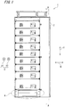
- FIG. 1 is a front view of electrical equipment 1 according to an example useful for understanding of the present invention, and which is not included under the scope of the claims.
- FIG. 1 the position of a ventilation portion 4 is particularly indicated by a two-dot dashed line.
- FIG. 2 is an internal side view of the electrical equipment 1 as opened along sectional line A-A shown in FIG. 1 , in an example useful for understanding of the present invention, and which is not included under the scope of the claims.
- the electrical equipment 1 is a switchboard as an example, and a housing 2 of the electrical equipment 1 stores a circuit breaker of the switchboard.
- a short-circuit fault may occur in a main circuit due to various causes such as aging deterioration of equipment, human error in maintenance inspection, and poor maintenance.
- an arc is generated at the part where the short-circuit occurs.
- the internal pressure is sharply increased inside the electrical equipment 1, whereby high-temperature high-pressure gas, i.e., so-called arc gas is generated.
- the housing 2 of the electrical equipment 1 is provided with the ventilation portion 4 for the purpose of ventilation and cooling.
- the ventilation portion 4 allows passage of gas, e.g., air and high-temperature high-pressure gas, between the inside and the outside of the housing 2 of the electrical equipment 1.
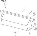
- FIG. 3 is a perspective view of the ventilation portion 4 in an example useful for understanding of the present invention, and which is not included under the scope of the claims.
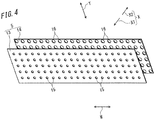
- FIG. 4 is a perspective view of a plurality of plate-shaped members 5 in an example useful for understanding of the present invention, and which is not included under the scope of the claims.
- FIG. 5 is a front view of the plurality of plate-shaped members 5 in an example useful for understanding of the present invention, and which is not included under the scope of the claims.
- the ventilation portion 4 has the plurality of plate-shaped members 5, and the plurality of plate-shaped members 5 are provided in an overlapping manner so as to be spaced by a gap S with their thickness directions X aligned with each other.
- the side outward of the ventilation portion 4 is referred to as "one side X1 in the thickness direction”
- the side inward of the ventilation portion 4 is referred to as "other side X2 in the thickness direction”.
- the ventilation portion 4 is provided at a front part of the housing 2.
- the one side X1 in the thickness direction coincides with the side frontward or outward of the housing 2, and the other side X2 in the thickness direction coincides with the side rearward or inward of the housing 2. Therefore, these sides may be referred to as frontward side X1 or outward side X1, and rearward side X2 or inward side X2.
- the ventilation portion 4 is provided with two plate-shaped members 5. Of the two plate-shaped members 5, the plate-shaped member 5 on the outward side X1 is referred to as "first plate-shaped member 13", and the plate-shaped member 5 on the inward side X2 is referred to as "second plate-shaped member 14".
- the plurality of plate-shaped members 5 each have a plurality of through holes 6.
- the plurality of through holes 6 penetrate each plate-shaped member 5 in the thickness direction X.
- the through holes 6 formed in the first plate-shaped member 13 are referred to as "first through holes 15”
- the through holes 6 formed in the second plate-shaped member 14 are referred to as "second through holes 16".
- the plurality of through holes 6 in each plate-shaped member 5 are formed at positions shifted from the plurality of through holes 6 in the other plate-shaped member 5 adjacent in the thickness direction X. That is, the first through holes 15 of the first plate-shaped member 13 and the second through holes 16 of the second plate-shaped member are formed at positions shifted from each other as seen in the thickness direction X.
- the aperture rates of the respective plate-shaped members 5 based on the through holes 6 are different from each other.
- the aperture rates of the plate-shaped members 5 are set such that the plate-shaped member 5 closer to the outward side X1 of the ventilation portion 4 has a smaller aperture rate. That is, the aperture rate of the first plate-shaped member 13 based on the first through holes 15 is set to be smaller than the aperture rate of the second plate-shaped member 14 based on the second through holes 16.
- FIG. 2 inside the switchboard as the electrical equipment 1, a bus space 11 for storing a horizontal bus and a vertical bus is provided on the other side X2 (rearward side) in the thickness direction, and function units 12 for performing, for example, switching of a switch, are provided on the one side X1 (frontward side) in the thickness direction.
- the ventilation portion 4 is provided at the lower part of the housing 2 of the electrical equipment 1.
- the housing 2 of the electrical equipment 1 in the present invention is simply referred to as "housing 2".
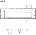
- FIG. 6 is a front view of the ventilation portion 4 in an example useful for understanding of the present invention, and which is not included under the scope of the claims.
- FIG. 6 is an enlarged view of the ventilation portion 4 indicated by the two-dot dashed line in FIG. 1 .
- FIG. 7 is a sectional view of the ventilation portion 4 taken along sectional line B ⁇ B shown in FIG. 6 , in an example useful for understanding of the present invention, and which is not included under the scope of the claims.
- each plate-shaped member 5 serves as an air passage for taking in air, during normal operation.
- the through holes 6 formed in each plate-shaped member 5 allow air to pass from the outward side X1 to the inward side X2.
- the first plate-shaped member 13 and the second plate-shaped member 14 are formed in a rectangular shape elongated in a lateral direction W as seen in the thickness direction X.
- the lateral direction W is the direction perpendicular to the thickness direction X and a vertical direction Y.
- the shape and the size of the first plate-shaped member 13 are the same as the shape and the size of the second plate-shaped member 14.
- the thickness of the first plate-shaped member 13 is the same as the thickness of the second plate-shaped member 14.
- the first plate-shaped member 13 and the second plate-shaped member 14 are arranged with their thickness directions X aligned with each other, so that the one side X1 in the thickness direction is directed to the outward side X1 of the housing 2, and the other side X2 in the thickness direction is directed to the inward side X2 of the housing 2.
- the first plate-shaped member 13 and the second plate-shaped member 14 each have the plurality of through holes 6.
- the first through holes 15 and the second through holes 16 are each formed in a round shape as seen in the thickness direction X. As shown in FIG. 4 , the inner diameter of the first through holes 15 is smaller than the inner diameter of the second through holes 16.
- the first through holes 15 and the second through holes 16 are formed so as to be arranged in the vertical direction Y and the lateral direction W.
- the number of the first through holes 15 per unit length is set to be equal to the number of the second through holes 16 per unit length. That is, the pitch of the first through holes 15 in the vertical direction Y is the same as the pitch of the second through holes 16. Also in the lateral direction W, the pitch of the first through holes 15 is set to be equal to the pitch of the second through holes 16.
- the aperture rate of the first plate-shaped member 13 based on the first through holes 15 is set to be smaller than the aperture rate of the second plate-shaped member 14 based on the second through holes 16.
- the aperture rate based on the through holes 6 is set to be greater for the plate-shaped member 5 closer to the inward side X2, and the aperture rate based on the through holes 6 is set to be smaller for the plate-shaped member 5 closer to the outward side X1.
- the pitches of the first through holes 15 and the second through holes 16 are set to be equal to or greater than two times the inner diameter of the second through holes 16 formed in the second plate-shaped member 14 on the inward side X2.
- a part forming the first plate-shaped member 13 exists as a part having a dimension equal to or greater than the inner diameter of the second through holes 16.
- the second plate-shaped member 14 both in the vertical direction Y and the lateral direction W, between the adjacent second through holes 16, a part forming the second plate-shaped member exists as a part having a dimension equal to or greater than the inner diameter of the second through holes 16.
- the first through holes 15 and the second through holes 16 are formed at positions shifted from each other when the first plate-shaped member 13 and the second plate-shaped member 14 are seen in the thickness direction X.
- the first through holes 15 and the second through holes 16 are located so as not to overlap each other.
- gas passing through the first through holes 15 and the second through holes 16 in the thickness direction X does not linearly pass from the space on the inward side X2 of the second plate-shaped member 14 to the space on the outward side X1 of the first plate-shaped member 13.
- the ventilation portion 4 allows discharge of the high-temperature high-pressure gas to the outside.
- the through holes 6 formed in the plate-shaped members 5 allow gas to pass from the inward side X2 to the outward side X1, whereby the high-temperature high-pressure gas generated in the housing is discharged to the outside.
- FIG. 7 where an example not included under the scope of the claims is shown, a discharge path of the high-temperature high-pressure gas is indicated by arrows P1.
- FIG. 8 is a sectional view of the plurality of plate-shaped members 5 as seen in the lateral direction W in an example useful for understanding of the present invention , and which is not included under the scope of the claims.
- FIG. 8 is an enlarged view of a part indicated by a two-dot dashed line in FIG. 7 .
- a discharge path of the high-temperature high-pressure gas is indicated by arrows P2.
- the high-temperature high-pressure gas generated on the inward side X2 of the second plate-shaped member 14 passes in the thickness direction X through the second through holes 16 formed in the second plate-shaped member 14.
- the high-temperature high-pressure gas having passed through the second through holes 16 blows to the part forming the first plate-shaped member 13. Therefore, the high-temperature high-pressure gas cannot linearly pass from the inward side X2 of the second plate-shaped member 14 to the outward side X1 of the first plate-shaped member 13.
- the gas passing through the second through holes 16 from the inward side X2 to the outward side X1 of the housing 2 is mixed with gas existing in the gap S between the first plate-shaped member 13 and the second plate-shaped member 14, and then passes through the first plate-shaped member 13.
- the through holes 6 of these plate-shaped members 5 do not overlap each other as seen in the thickness direction X.
- the gas existing in the gap S between the first plate-shaped member 13 and the second plate-shaped member 14 is air at the room temperature.
- the air that has existed between the first plate-shaped member 13 and the second plate-shaped member 14 during normal operation is partially pushed out to the outward side X1 of the first through holes 15 by the high-temperature high-pressure gas from the inward side X2, when short-circuit occurs.
- the remaining air that has not been pushed out to the outward side X1 by the high-temperature high-pressure gas is mixed with the high-temperature high-pressure gas in the gap S between the first plate-shaped member 13 and the second plate-shaped member 14.
- the mixed gas of the high-temperature high-pressure gas and the air has a lower temperature as compared to the high-temperature high-pressure gas located on the inward side X2 of the second plate-shaped member 14.
- first plate-shaped member 13 and the second plate-shaped member 14 respectively allow passage of the high-temperature high-pressure gas through the plurality of first through holes 15 and the plurality of second through holes 16, pressure loss occurs when the gas passes. Therefore, the pressure on the inward side X2 of the second plate-shaped member 14 is not directly propagated to the outside of the housing 2. The greater the pressure loss occurring in the passing gas is, the greater the pressure applied to the first plate-shaped member 13 and the second plate-shaped member 14 by the air is.
- the plate-shaped member 5 closer to the inward side X2 which is closer to the generation source of the high-temperature high-pressure gas, is subjected to a greater pressure from the high-temperature high-pressure gas than the plate-shaped member 5 on the outward side X1.
- the center part of the plate-shaped member 5 is pushed to the outward side X1 and is greatly deformed when subjected to the pressure from the high-temperature high-pressure gas.
- the plate-shaped member 5 undergoes elastic deformation or plastic deformation.
- the center part of the second plate-shaped member 14 is displaced to the outward side X1, the volume of the gap S between the first plate-shaped member 13 and the second plate-shaped member 14 is reduced.
- the amount of air to be mixed with the high-temperature high-pressure gas that has passed through the second plate-shaped member 14 from the inward side X2 to the outward side X1 decreases, so that cooling efficiency for the high-temperature high-pressure gas is reduced.
- the first plate-shaped member 13 having a smaller aperture rate than the aperture rate of the second plate-shaped member 14 is provided on the outward side X1 of the second plate-shaped member 14, whereby pressure loss due to the second plate-shaped member 14 is reduced and thus rigidity required for the second plate-shaped member 14 is reduced.
- the pressure of gas passing from the inward side X2 to the outward side X1 of the ventilation portion 4 is reduced stepwise by the second through holes 16 of the second plate-shaped member 14 and the first through holes 15 of the first plate-shaped member 13.
- the pressure is prevented from being concentrated on the second plate-shaped member 14 located on the inward side X2 of the housing 2.
- a hood 21 provided to the ventilation portion 4 will be described.
- the hood 21 covers the first plate-shaped member 13 and the second plate-shaped member 14 from the outward side X1.
- the hood 21 changes the advancement direction of gas discharged through the ventilation portion 4.
- the hood 21 changes the advancement direction of the high-temperature high-pressure gas passing through the through holes 6 of the plate-shaped members 5 from the inward side X2 to the outward side X1 of the ventilation portion 4, to a direction perpendicular to the thickness direction X of the plate-shaped member 5.
- the "perpendicular direction" may be, for example, a direction toward one side in the vertical direction Y, or a direction toward one side in the lateral direction W.
- This direction is optionally selected in accordance with the environment in which the electrical equipment 1 is installed. It is not preferable that, when short-circuit occurs, the high-temperature high-pressure gas is ejected toward a passage that can serve as a conveyance path for devices other than the electrical equipment 1.
- the ventilation portion 4 is provided at a lower part of the housing 2 which is close to the floor. Therefore, the hood 21 changes the advancement direction of the high-temperature high-pressure gas advancing through the plate-shaped members 5 from the inward side X2 to the outward side X1, to a direction of advancing downward.
- the hood 21 may be configured to change the advancement direction of the high-temperature high-pressure gas ejected from the inward side X2, to a direction of advancing upward.
- the hood 21 may be configured to change the advancement direction of the high-temperature high-pressure gas ejected from the inward side X2, to a direction of advancing toward the wall.
- the discharge direction of the high-temperature high-pressure gas is set to an appropriate direction in accordance with the direction of the opening of the hood 21.
- the hood 21 not only has a function of directing, to an optional direction, the high-temperature high-pressure gas ejected through the first plate-shaped member 13 and the second plate-shaped member 14 from the inward side X2 to the outward side X1 of the housing, but also contributes to cooling for the high-temperature high-pressure gas.
- the high-temperature high-pressure gas having passed through the first plate-shaped member 13 from the inward side X2 to the outward side X1 passes through the space that is on the inward side X2 of the hood 21 and on the outward side X1 of the first plate-shaped member 13.
- the flow path for the high-temperature high-pressure gas to be discharged to the outward side X1 of the housing 2 is elongated, so that the time period until the high-temperature high-pressure gas is discharged is prolonged.
- the high-temperature high-pressure gas is mixed with air in the space that is on the inward side X2 of the hood 21 and on the outward side X1 of the first plate-shaped member 13. In this way, providing the hood 21 allows the high-temperature high-pressure gas to be further cooled until the high-temperature high-pressure gas is discharged from the housing 2.
- the plurality of plate-shaped members 5 are provided, when high-temperature high-pressure gas is generated inside, the pressure of the high-temperature high-pressure gas can be gradually reduced by the plurality of plate-shaped members 5 from the inward side X2 to the outward side X1 of the ventilation portion 4.
- the plurality of through holes 6 of each plate-shaped member 5 are formed at positions shifted from the plurality of through holes 6 of another plate-shaped member 5 adjacent in the thickness direction X, whereby the high-temperature high-pressure gas can be prevented from being linearly ejected from the inward side X2 to the outward side X1 of the ventilation portion 4.
- gas flowing out from the plate-shaped member 5 on the inward side X2 of the ventilation portion 4 toward the outward side X1 of the ventilation portion 4 is mixed with air having the same temperature as the outside air, in the gap S between the plate-shaped members 5, and thus is cooled. Since the aperture rates of these plate-shaped members are different from each other, roles as to mechanical strength, pressure loss of flowing air, cooling efficiency, and the like can be divided between the plate-shaped member 5 located on the inward side X2 and the plate-shaped member 5 located on the outward side X1. Therefore, reduction in mechanical strength required for each plate-shaped member 5 and prevention of deformation of the ventilation portion 4, and cooling of ejected high-temperature high-pressure gas, can be both achieved efficiently.
- the aperture rates of the plate-shaped members are set such that the plate-shaped member closer to the outward side of the ventilation portion has a smaller aperture rate. Therefore, the pressure loss can be gradually increased from the inward side X2 toward the outward side X1 of the ventilation portion 4.
- load due to the pressure of the generated high-temperature high-pressure gas can be prevented from being concentrated on the plate-shaped member 5 on the inward side X2. Accordingly, shock by generation of the high-temperature high-pressure gas can be relaxed. Therefore, mechanical strength required for each plate-shaped member 5 can be reduced, deformation of the ventilation portion 4 can be prevented, and ejected high-temperature high-pressure gas can be efficiently cooled.
- the advancement direction of gas discharged through the ventilation portion 4 is changed by the hood 21. Therefore, when the high-temperature high-pressure gas is discharged, the high-temperature high-pressure gas can be prevented from adversely affecting another device near the electrical equipment 1.
- the flow path for the high-temperature high-pressure gas to be discharged to the outward side X1 of the housing 2 is elongated as compared to the case of not providing the hood 21, and thus the time period until the high-temperature high-pressure gas is discharged is prolonged. Thus, cooling efficiency for the high-temperature high-pressure gas can be improved.
- the high-temperature high-pressure gas is mixed with air in the space that is on the inward side X2 of the hood 21 and on the outward side X1 of the first plate-shaped member 13. Therefore, the high-temperature high-pressure gas can be cooled by the air, by the time when the gas is discharged to the outward side X1 of the hood 21.
- Embodiment 1 is similar to the example useful for understanding described above. Hereinafter, difference of embodiment 1 from the example useful for understanding will be mainly described.
- FIG. 9 is a perspective view of a plurality of plate-shaped members 5 in embodiment 1 of the present invention.
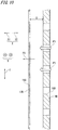
- FIG. 10 is a sectional view of the plurality of plate-shaped members 5 as seen in the lateral direction W, in embodiment 1 of the present invention.
- the aperture rates of the plate-shaped members 5 based on the through holes 6 are set such that the plate-shaped member 5 closer to the outward side X1 of the ventilation portion 4 has a greater aperture rate.
- the ventilation portion 4 in the present embodiment is provided with two plate-shaped members 5.
- first plate-shaped member 13B the plate-shaped member 5 on the outward side X1
- second plate-shaped member 14B the plate-shaped member 5 on the inward side X2
- the thickness of the second plate-shaped member 14B in the present embodiment is set to be greater than the thickness of the first plate-shaped member 13B.
- the through holes 6 formed in the first plate-shaped member 13B are referred to as "first through holes 15B", and the through holes 6 formed in the second plate-shaped member 14B are referred to as "second through holes 16B".
- the first through holes 15B and the second through holes 16B have a round shape as seen in the thickness direction X. As shown in FIG. 9 , the inner diameter of the first through holes 15B is greater than the inner diameter of the second through holes 16B.
- the pitches of the first through holes 15B and the second through holes 16B are set to be equal to or greater than two times the inner diameter of the first through holes 15B formed in the first plate-shaped member 13B on the outward side X1.
- a part forming the first plate-shaped member 13B exists as a part having a dimension equal to or greater than the inner diameter of the first through holes 15B.
- a part forming the second plate-shaped member 14B exists as a part having a dimension equal to or greater than the inner diameter of the first through holes 15B.
- the first through holes 15B and the second through holes 16B are formed at positions shifted from each other when the first plate-shaped member 13B and the second plate-shaped member 14B are seen in the thickness direction X.
- the first through holes 15B and the second through holes 16B are located so as not to overlap each other.
- gas passing through the first through holes 15B and the second through holes 16B in the thickness direction X does not linearly pass from the space on the inward side X2 of the second plate-shaped member 14B to the space on the outward side X1 of the first plate-shaped member 13B.
- FIG. 10 shows, by arrows P3, high-temperature high-pressure gas passing through the second through holes 16B and the first through holes 15B when short-circuit occurs.
- the inner diameter of the second through holes 16B is set to be smaller than the inner diameter of the first through holes 15B. Therefore, pressure loss due to the second plate-shaped member 14B for high-temperature high-pressure gas passing through the second plate-shaped member 14B is greater than pressure loss due to the first plate-shaped member 13B.
- the second plate-shaped member 14B is subjected to a greater pressure from the inward side X2 toward the outward side X1 than the first plate-shaped member 13B.
- the second plate-shaped member 14B has a greater thickness than the first plate-shaped member 13B, so that the second plate-shaped member 14B has a sufficient mechanical strength to withstand the pressure from the inward side X2 when short-circuit occurs. Since the second plate-shaped member 14B is thicker than the first plate-shaped member 13B, the distance by which air passes through the second through hole 16B in the thickness direction X is longer than the distance by which air passes through the first through hole 15B in the thickness direction X. Also by this, the pressure loss due to the second plate-shaped member 14B becomes greater than the pressure loss due to the first plate-shaped member 13B.
- the air present in the gap S between the first plate-shaped member 13B and the second plate-shaped member 14B continues to be constantly replaced with the outside air during normal operation of the electrical equipment 1. Since the aperture rate of the first plate-shaped member 13B is set to be great, the outside air readily enters the gap S as compared to the case where the aperture rate of the first plate-shaped member 13B is small. Therefore, the greater the aperture rate of the first plate-shaped member 13B is, the more likely the air present in the gap S is replaced with the air on the outward side X1 of the first plate-shaped member 13B.
- the temperature inside the housing 2 is usually higher than the temperature of the outside air. Therefore, the air present in the gap S between the first plate-shaped member 13B and the second plate-shaped member 14B is maintained well in a low-temperature state if the air is likely to be replaced with the air on the outward side X1. Since the aperture rate of the first plate-shaped member 13B is set to be high, the air present in the gap S between the first plate-shaped member 13B and the second plate-shaped member 14B is readily maintained at a low temperature. Since the air in the gap S is maintained at a low temperature, it is possible to efficiently perform cooling in the gap S between the first plate-shaped member 13B and the second plate-shaped member 14B when short-circuit occurs.
- the aperture rate of the plate-shaped member 5 closer to the inward side X2 is set to be smaller, and the plate-shaped member 5 closer to the inward side X2 is formed by a thicker member having higher rigidity.
- pressure loss of the high-temperature high-pressure gas flowing out from the inside is greater at the plate-shaped member 5 closer to the inward side X2 of the ventilation portion 4. Therefore, replacement with high-temperature high-pressure gas is less likely to occur in the gap S closer to the outward side X1 of the ventilation portion 4, among the gaps S present on the inward sides X2 of the respective plate-shaped members 5.
- cooling efficiency in the gap S between the plate-shaped members 5 can be enhanced as compared to the case where the aperture rate is set to be smaller for the plate-shaped member 5 closer to the outward side X1 of the ventilation portion 4.
- mechanical strength and pressure loss of air that flows out are assigned to the plate-shaped member 5 on the ventilation portion 4 side, and cooling efficiency is assigned to the plate-shaped member 5 on the outward side X1 of the ventilation portion 4, whereby different roles are assigned among the plurality of plate-shaped members 5.
- Embodiment 2 is similar to the example useful for understanding described above. Hereinafter, difference of embodiment 2 from the example useful for understanding will be described.
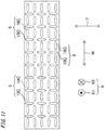
- FIG. 11 is a front view of a plurality of plate-shaped members 5 in embodiment 2 of the present invention.
- the outer shapes of the plurality of plate-shaped members 5 are designed to be a rectangular shape as seen in the thickness direction X.
- a plurality of through holes 6 of at least one of the plurality of plate-shaped members 5 are formed in a shape elongated in parallel to the long-side direction of the plate-shaped member 5.
- the ventilation portion 4 in the present embodiment is provided with two plate-shaped members 5.
- first plate-shaped member 13C the plate-shaped member 5 on the outward side X1
- second plate-shaped member 14C the plate-shaped member 5 on the inward side X2
- the first plate-shaped member 13C and the second plate-shaped member 14C are arranged with their long-side directions aligned with the lateral direction W of the electrical equipment 1. Regarding the outer appearance, the shape and the size of the first plate-shaped member 13C are the same as the shape and the size of the second plate-shaped member 14C.
- the through holes 6 formed in the first plate-shaped member 13C are referred to as "first through holes 15C", and the through holes 6 formed in the second plate-shaped member 14C are referred to as "second through hole 16C".
- the first through holes 15C are formed in a shape elongated in the short-side direction of the first plate-shaped member 13C, i.e., the vertical direction Y.
- the second through holes 16C are formed in a shape elongated in the long-side direction of the second plate-shaped member 14C, i.e., the lateral direction W.
- the shapes and the sizes are the same, but the formation directions are different.
- a force needed for bending to deform the center part relative to both ends in the long-side direction is smaller than a force needed for bending to deform the center part relative to both ends in the short-side direction.
- the center parts of the first plate-shaped member 13C and the second plate-shaped member 14C are readily deformed relative to both ends in the long-side direction of each plate-shaped member 5.
- bending to deform the center part relative to both ends in the long-side direction is referred to as “long-side bending”
- bending to deform the center part relative to both ends in the short-side direction is referred to as “short-side bending”.
- the through holes 6 have a round shape, rigidity of the plate-shaped member 5 decreases as the aperture rate increases.
- by forming the through holes 6 so as to be elongated in the long-side direction mechanical strength against long-side bending is maintained at a high level and a high aperture rate is ensured, as compared to the case where the through holes 6 are formed in a round shape or a shape elongated in the short-side direction.
- one of the plate-shaped members 5 other than the one closest to the outward side X1 is made to have such a configuration.
- the plate-shaped member 5 closest to the inward side X2 is made to have such a configuration.
- the first through holes 15C are formed in a shape elongated in the short-side direction.
- the first through holes 15C do not overlap the second through holes 16C as seen in the thickness direction X. Therefore, for example, the first through holes 15C may be formed in a round shape, or may be formed in a shape elongated in the long-side direction.
- At least one plate-shaped member 5 has through holes 6 formed in a shape elongated in the long-side direction. Therefore, as compared to the case of forming through holes 6 in a shape elongated in the short-side direction under the same aperture rate, it is possible to enhance rigidity against bending stress of pressing the long-side-direction center part in the thickness direction X relative to both ends in the long-side direction. Thus, owing to the shape of the through holes 6 formed in the plate-shaped member 5, reduction in rigidity due to increase in the aperture rate can be suppressed.
- each plate-shaped member 5 The number and the size of the through holes 6 formed in each plate-shaped member 5, the aperture rate of each plate-shaped member 5, and the like are not limited to those shown in the drawings, but may be freely changed, as long as these fall within the scope of the claims.
- the case of providing two plate-shaped members 5 to the ventilation portion 4 has been described.
- three or more plate-shaped members 5 may be provided.
- the aperture rates are set to be sequentially changed from the inward side X2 toward the outward side X1.
- the aperture rates and the thicknesses of the plate-shaped members 5 are set to be sequentially changed from the inward side X2 toward the outward side X1.
- roles as to mechanical strength, pressure loss, and cooling efficiency can be divided between the plate-shaped member 5 on the inward side X2 and the plate-shaped member 5 on the outward side X1.
- the housing 2 of the electrical equipment 1 which enables reduction in mechanical strength required for each plate-shaped member 5, prevents deformation of a part that allows gas discharge, and enables ejected high-temperature high-pressure gas to be efficiently cooled.
Description
- The present invention relates to an electrical equipment housing in which electrical equipment such as a circuit breaker is stored.
- In a conventional example of an electrical equipment housing provided with an intake portion, a plate-shaped member having through holes is provided at an intake portion for ventilation. When high-temperature high-pressure gas is generated upon an internal short-circuit fault, the through holes formed in the plate-shaped member allow discharge of the high-temperature high-pressure gas. In the through holes, fluid energy loss of fluid moving in the discharge direction is set to be greater than fluid energy loss of fluid moving in the intake direction. The parts defining the through holes in the plate-shaped member are formed such that the shape coefficient for fluid energy loss in the discharge direction is greater than the shape coefficient for energy loss in the intake direction.
-
Document CN 1 312 711 C , according to its abstract, states an arc-suppressing chamber with a gas extinction device including an arc isolation wall containing multiple arc extinction gratin plates in it characterizing in setting at least two-layers of porous screens near the exit of the chamber, holes opened on the two adjacent screens arc staggered, multiple round free-erasing posts arc set between adjacent two screens above the holes of the screen inside the adjacent internal layers expressed in an arc face with the hole contact face. When the arc is interrupted in the chamber, the ionized gas passes through the porous screens and free-erasing posts layer by layer alternately to be cooled effectively. The diameter of the hole is different. -
Document EP 2 145 365 A1 , according to its abstract, states a partition apparatus for an electrical power distributor unit, having partition means for placing behind a casing part, which is provided with ventilation openings, of the electrical power distributor unit, in particular a switch panel door, wherein the partition means are designed such that, in normal operating conditions, they ensure an air flow through the ventilation openings in the interior of the electrical power distributor unit, or out of the interior of the electrical power distributor unit, and in the event of a fault, and under the influence of a pressure wave, cover the ventilation openings such that the pressure wave and hot gases are passed to the exterior in a greatly reduced form. In order to improve the resistance of the partition apparatus to mechanical damage at least one first metal partition sheet and one second metal partition sheet are provided as partition means, are each provided with aperture openings and are arranged one above the other, wherein the two metal partition sheets are curved in a convex form to different extents starting from the casing part which is provided with the ventilation openings, and wherein the radii of curvature of the metal partition sheets are variable by the metal partition sheets being bent under the influence of the pressure wave. - Document
US 4 484 690 A , according to its abstract, states a flame arresting ventilated wall or panel for an explosion-proof enclosure comprises a stack of aluminum sheets apertured to provide a plurality of discrete, generally parallel gas flow channels disposed in crisscross patterns across the heights and widths of the sheets. Fasteners tie the sheets together into a rigid structure and are disposed in patterns surrounding and individually uniformly supporting the gas flow channels from the center of the sheets to their outer edge. Combinations of three different punched sheets are used, namely, first and second apertured sheets spaced apart by relatively thin separator sheets. Along each of the plurality of gas flow channels, each separtor sheet has a large window and the first and second apertured sheets have separate arrays of nine and sixteen flow holes, respectively, registered with the windows, each array having a total cross-sectional area about one-fourth of each corresponding window. - Document
WO 2008/136113 A1 , according to its abstract, states a metal-closed switch gear in which an electrical machine is housed inside a box having an inlet and an outlet. Inside the casing part of the box where the inlet is bored, an intra-board partition plate functioning as a ventilating partition plate having a vent hole opposed to the inlet is arranged apart from the casing part so that the intra-board partition plate may suppress discharging of a high-temperature ark gas from the inlet to the outside in occurrence of a short circuit in a cable chamber inside the box. - Document
US 2014/166623 A1 , according to its abstract, states that a muffler for enhanced arc protection is described. In the case of an internal arc event in an electrical enclosure, the muffler exhausts arc gas and plasma parallel to the enclosure surface, instead of directly forward where persons may be located. The muffler includes perforated plates and baffle plates in its interior space. The perforated plates have offset perforation patterns from one another, and the baffle plates are provided on opposing walls, causing the plasma and gas to make multiple directional changes. The perforated plates also filter the arc gas and plasma. These directional changes and filtering result in an energy reduction from the exhaust, which provides an increased margin of safety. In addition, the muffler provides an adequate level of ventilation in the enclosure, thus keeping the components cool. - Document
KR 2016 0130694 A - Patent Document 1:
Japanese Laid-Open Patent Publication No. 2011-259600 - Increasing fluid energy loss in the discharge direction makes it possible to more prevent ejection of the high-temperature high-pressure gas, but causes a problem of requiring mechanical strength of the housing. In the case where a plurality of plate-shaped members are provided in an overlapping manner, due to the great fluid energy loss in the discharge direction, load is applied to the inner-side plate-shaped member when gas is ejected from inside, and thus the inner-side plate-shaped member is deformed to come into contact with the outer-side plate-shaped member. When the two plate-shaped members come into contact with each other, the space between the two plate-shaped members is reduced, so that it becomes difficult for ejected high-temperature high-pressure gas to be mixed with the outside air in the space between the plate-shaped members, thus causing a problem of decreasing cooling efficiency for the ejected gas.
- An object of the present invention is to provide an electrical equipment housing which enables reduction in mechanical strength required for each plate-shaped member, prevents deformation of a part that allows gas discharge, and enables gas in the housing to be efficiently cooled.
- There is provided an electrical equipment housing comprising a ventilation portion that allows gas to pass between inside and outside, wherein the ventilation portion has a plurality of plate-shaped members provided in an overlapping manner so as to be spaced from each other with their thickness directions aligned with each other, the plurality of plate-shaped members each have a plurality of through holes penetrating through the plate-shaped member in the thickness direction, the plurality of through holes in each plate-shaped member are, as seen in the thickness direction, formed at positions shifted from the plurality of through holes in another plate-shaped member adjacent in the thickness direction, aperture rates of the plate-shaped members based on the pluralities of through holes are different from each other, of the plurality of plate-shaped members, the plate-shaped member on an inward side has a greater thickness than the plate-shaped member on an outward side, and the aperture rates of the plate-shaped members are set such that the plate-shaped member closer to an outward side of the ventilation portion has a greater aperture rate.
- The electrical equipment housing according to the present invention enables reduction in mechanical strength required for each plate-shaped member, prevents deformation of a part that allows gas discharge, and enables gas in the housing to be efficiently cooled.
-
- [
FIG. 1] FIG. 1 is a front view of electrical equipment in an example useful for understanding of the present invention, and which is not under the scope of the claims. - [
FIG. 2] FIG. 2 is an internal side view of the electrical equipment as opened along sectional line A-A inFIG. 1 , in an example useful for understanding of the present invention , and which is not under the scope of the claims. - [
FIG. 3] FIG. 3 is a perspective view of a ventilation portion in an example useful for understanding of the present invention, and which is not under the scope of the claims. - [
FIG. 4] FIG. 4 is a perspective view of a plurality of plate-shaped members in an example useful for understanding of the present invention, and which is not under the scope of the claims. - [
FIG. 5] FIG. 5 is a front view of the plurality of plate-shaped members in an example useful for understanding of the present invention, and which is not under the scope of the claims. - [
FIG. 6] FIG. 6 is a front view of the ventilation portion in an example useful for understanding of the present invention , and which is not under the scope of the claims. - [
FIG. 7] FIG. 7 is a sectional view of the ventilation portion taken along sectional line B―B inFIG. 6 , in an example useful for understanding of the present invention , and which is not under the scope of the claims. - [
FIG. 8] FIG. 8 is a sectional view of the plurality of plate-shaped members as seen in the lateral direction, in an example useful for understanding of the present invention, and which is not under the scope of the claims. - [
FIG. 9] FIG. 9 is a perspective view of a plurality of plate-shaped members inembodiment 1 of the present invention. - [
FIG. 10] FIG. 10 is a sectional view of the plurality of plate-shaped members as seen in the lateral direction, inembodiment 1 of the present invention. - [
FIG. 11] FIG. 11 is a front view of a plurality of plate-shaped members inembodiment 2 of the present invention. - Hereinafter, with reference to the drawings, several embodiments of the present invention will be described. In the following description, parts that correspond to matters having been already described in any embodiment preceding each embodiment are denoted by the same reference characters, and the same description thereof may be omitted. In the case where only a part of the configuration is described, the other part of the configuration is the same as that already described.
-
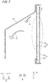
FIG. 1 is a front view ofelectrical equipment 1 according to an example useful for understanding of the present invention, and which is not included under the scope of the claims. - In
FIG. 1 , the position of aventilation portion 4 is particularly indicated by a two-dot dashed line.FIG. 2 is an internal side view of theelectrical equipment 1 as opened along sectional line A-A shown inFIG. 1 , in an example useful for understanding of the present invention, and which is not included under the scope of the claims. - The
electrical equipment 1 according to the present example, not included under the scope of the claims, is a switchboard as an example, and ahousing 2 of theelectrical equipment 1 stores a circuit breaker of the switchboard. In operation of theelectrical equipment 1, although in rare case, a short-circuit fault may occur in a main circuit due to various causes such as aging deterioration of equipment, human error in maintenance inspection, and poor maintenance. When a short-circuit fault occurs, an arc is generated at the part where the short-circuit occurs. Then, due to the arc energy, the internal pressure is sharply increased inside theelectrical equipment 1, whereby high-temperature high-pressure gas, i.e., so-called arc gas is generated. Thehousing 2 of theelectrical equipment 1 is provided with theventilation portion 4 for the purpose of ventilation and cooling. Theventilation portion 4 allows passage of gas, e.g., air and high-temperature high-pressure gas, between the inside and the outside of thehousing 2 of theelectrical equipment 1. -
FIG. 3 is a perspective view of theventilation portion 4 in an example useful for understanding of the present invention, and which is not included under the scope of the claims. -
FIG. 4 is a perspective view of a plurality of plate-shaped members 5 in an example useful for understanding of the present invention, and which is not included under the scope of the claims. -
FIG. 5 is a front view of the plurality of plate-shapedmembers 5 in an example useful for understanding of the present invention, and which is not included under the scope of the claims. Theventilation portion 4 has the plurality of plate-shapedmembers 5, and the plurality of plate-shapedmembers 5 are provided in an overlapping manner so as to be spaced by a gap S with their thickness directions X aligned with each other. The side outward of theventilation portion 4 is referred to as "one side X1 in the thickness direction", and the side inward of theventilation portion 4 is referred to as "other side X2 in the thickness direction". In the present example, not included under the scope of the claims, theventilation portion 4 is provided at a front part of thehousing 2. Therefore, the one side X1 in the thickness direction coincides with the side frontward or outward of thehousing 2, and the other side X2 in the thickness direction coincides with the side rearward or inward of thehousing 2. Therefore, these sides may be referred to as frontward side X1 or outward side X1, and rearward side X2 or inward side X2. In the present example, not included under the scope of the claims, theventilation portion 4 is provided with two plate-shapedmembers 5. Of the two plate-shapedmembers 5, the plate-shapedmember 5 on the outward side X1 is referred to as "first plate-shapedmember 13", and the plate-shapedmember 5 on the inward side X2 is referred to as "second plate-shapedmember 14". - The plurality of plate-shaped
members 5 each have a plurality of throughholes 6. The plurality of throughholes 6 penetrate each plate-shapedmember 5 in the thickness direction X. The throughholes 6 formed in the first plate-shapedmember 13 are referred to as "first throughholes 15", and the throughholes 6 formed in the second plate-shapedmember 14 are referred to as "second throughholes 16". As seen in the thickness direction X, the plurality of throughholes 6 in each plate-shapedmember 5 are formed at positions shifted from the plurality of throughholes 6 in the other plate-shapedmember 5 adjacent in the thickness direction X. That is, the first throughholes 15 of the first plate-shapedmember 13 and the second throughholes 16 of the second plate-shaped member are formed at positions shifted from each other as seen in the thickness direction X. The aperture rates of the respective plate-shapedmembers 5 based on the throughholes 6 are different from each other. In the present example, not included under the scope of the claims, the aperture rates of the plate-shapedmembers 5 are set such that the plate-shapedmember 5 closer to the outward side X1 of theventilation portion 4 has a smaller aperture rate. That is, the aperture rate of the first plate-shapedmember 13 based on the first throughholes 15 is set to be smaller than the aperture rate of the second plate-shapedmember 14 based on the second through holes 16. - As shown in
FIG. 2 , inside the switchboard as theelectrical equipment 1, abus space 11 for storing a horizontal bus and a vertical bus is provided on the other side X2 (rearward side) in the thickness direction, andfunction units 12 for performing, for example, switching of a switch, are provided on the one side X1 (frontward side) in the thickness direction. As shown inFIG. 1 , theventilation portion 4 is provided at the lower part of thehousing 2 of theelectrical equipment 1. Hereinafter, thehousing 2 of theelectrical equipment 1 in the present invention is simply referred to as "housing 2".FIG. 6 is a front view of theventilation portion 4 in an example useful for understanding of the present invention, and which is not included under the scope of the claims. - In addition,
FIG. 6 is an enlarged view of theventilation portion 4 indicated by the two-dot dashed line inFIG. 1 .FIG. 7 is a sectional view of theventilation portion 4 taken along sectional line B―B shown inFIG. 6 , in an example useful for understanding of the present invention, and which is not included under the scope of the claims. - Of the
ventilation portion 4, the structure of each plate-shapedmember 5 will be particularly described. Theventilation portion 4 serves as an air passage for taking in air, during normal operation. The throughholes 6 formed in each plate-shapedmember 5 allow air to pass from the outward side X1 to the inward side X2. The first plate-shapedmember 13 and the second plate-shapedmember 14 are formed in a rectangular shape elongated in a lateral direction W as seen in the thickness direction X. The lateral direction W is the direction perpendicular to the thickness direction X and a vertical direction Y. Regarding the outer appearances, the shape and the size of the first plate-shapedmember 13 are the same as the shape and the size of the second plate-shapedmember 14. The thickness of the first plate-shapedmember 13 is the same as the thickness of the second plate-shapedmember 14. The first plate-shapedmember 13 and the second plate-shapedmember 14 are arranged with their thickness directions X aligned with each other, so that the one side X1 in the thickness direction is directed to the outward side X1 of thehousing 2, and the other side X2 in the thickness direction is directed to the inward side X2 of thehousing 2. - The first plate-shaped
member 13 and the second plate-shapedmember 14 each have the plurality of throughholes 6. The first throughholes 15 and the second throughholes 16 are each formed in a round shape as seen in the thickness direction X. As shown inFIG. 4 , the inner diameter of the first throughholes 15 is smaller than the inner diameter of the second through holes 16. - The first through
holes 15 and the second throughholes 16 are formed so as to be arranged in the vertical direction Y and the lateral direction W. In the vertical direction Y, the number of the first throughholes 15 per unit length is set to be equal to the number of the second throughholes 16 per unit length. That is, the pitch of the first throughholes 15 in the vertical direction Y is the same as the pitch of the second through holes 16. Also in the lateral direction W, the pitch of the first throughholes 15 is set to be equal to the pitch of the second through holes 16. - Thus, the aperture rate of the first plate-shaped
member 13 based on the first throughholes 15 is set to be smaller than the aperture rate of the second plate-shapedmember 14 based on the second through holes 16. In the case where three or more plate-shapedmembers 5 are provided, the aperture rate based on the throughholes 6 is set to be greater for the plate-shapedmember 5 closer to the inward side X2, and the aperture rate based on the throughholes 6 is set to be smaller for the plate-shapedmember 5 closer to the outward side X1. - In both of the vertical direction Y and the lateral direction W, the pitches of the first through
holes 15 and the second throughholes 16 are set to be equal to or greater than two times the inner diameter of the second throughholes 16 formed in the second plate-shapedmember 14 on the inward side X2. Thus, in both of the vertical direction Y and the lateral direction W, between the adjacent first throughholes 15, a part forming the first plate-shapedmember 13 exists as a part having a dimension equal to or greater than the inner diameter of the second through holes 16. Also regarding the second plate-shapedmember 14, both in the vertical direction Y and the lateral direction W, between the adjacent second throughholes 16, a part forming the second plate-shaped member exists as a part having a dimension equal to or greater than the inner diameter of the second through holes 16. - As shown in
FIG. 5 , in a state in which the first plate-shapedmember 13 and the second plate-shapedmember 14 are arranged in theventilation portion 4, the first throughholes 15 and the second throughholes 16 are formed at positions shifted from each other when the first plate-shapedmember 13 and the second plate-shapedmember 14 are seen in the thickness direction X. Thus, when the first plate-shapedmember 13 and the second plate-shapedmember 14 are seen in the thickness direction X, the first throughholes 15 and the second throughholes 16 are located so as not to overlap each other. Therefore, gas passing through the first throughholes 15 and the second throughholes 16 in the thickness direction X does not linearly pass from the space on the inward side X2 of the second plate-shapedmember 14 to the space on the outward side X1 of the first plate-shapedmember 13. - Next, a phenomenon when short-circuit occurs in the
electrical equipment 1, and the function of theventilation portion 4 when short-circuit occurs, will be described. When short-circuit occurs in theelectrical equipment 1 or at any part of an external circuit electrically connected to the circuit of theelectrical equipment 1 and excessive current occurs in the circuit due to the short-circuit, high-temperature high-pressure gas is generated by arc energy in theelectrical equipment 1. In order to prevent failure of theelectrical equipment 1 and damage of thehousing 2 due to instantaneous generation of the high-temperature high-pressure gas, theventilation portion 4 allows discharge of the high-temperature high-pressure gas to the outside. Specifically, the throughholes 6 formed in the plate-shapedmembers 5 allow gas to pass from the inward side X2 to the outward side X1, whereby the high-temperature high-pressure gas generated in the housing is discharged to the outside. - In
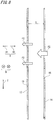
FIG. 7 , where an example not included under the scope of the claims is shown, a discharge path of the high-temperature high-pressure gas is indicated by arrows P1.FIG. 8 is a sectional view of the plurality of plate-shapedmembers 5 as seen in the lateral direction W in an example useful for understanding of the present invention , and which is not included under the scope of the claims. - In addition,
FIG. 8 is an enlarged view of a part indicated by a two-dot dashed line inFIG. 7 . Also inFIG. 8 , as inFIG. 7 , a discharge path of the high-temperature high-pressure gas is indicated by arrows P2. The high-temperature high-pressure gas generated on the inward side X2 of the second plate-shapedmember 14 passes in the thickness direction X through the second throughholes 16 formed in the second plate-shapedmember 14. The high-temperature high-pressure gas having passed through the second throughholes 16 blows to the part forming the first plate-shapedmember 13. Therefore, the high-temperature high-pressure gas cannot linearly pass from the inward side X2 of the second plate-shapedmember 14 to the outward side X1 of the first plate-shapedmember 13. - Thus, the gas passing through the second through
holes 16 from the inward side X2 to the outward side X1 of thehousing 2 is mixed with gas existing in the gap S between the first plate-shapedmember 13 and the second plate-shapedmember 14, and then passes through the first plate-shapedmember 13. In the case where three or more plate-shapedmembers 5 are provided, it suffices that two plate-shapedmembers 5 adjacent in the thickness direction X are configured such that the throughholes 6 of these plate-shapedmembers 5 do not overlap each other as seen in the thickness direction X. For example, even if the throughholes 6 of two plate-shapedmembers 5 located separately from each other on the inward side X2 and the outward side X1 with one plate-shapedmember 5 therebetween are formed so as to overlap each other in the thickness direction X, linear movement of gas passing through the throughholes 6 from the inward side X2 to the outward side X1 is prevented by the plate-shapedmember 5 located therebetween. - During normal operation, the gas existing in the gap S between the first plate-shaped
member 13 and the second plate-shapedmember 14 is air at the room temperature. The air that has existed between the first plate-shapedmember 13 and the second plate-shapedmember 14 during normal operation is partially pushed out to the outward side X1 of the first throughholes 15 by the high-temperature high-pressure gas from the inward side X2, when short-circuit occurs. The remaining air that has not been pushed out to the outward side X1 by the high-temperature high-pressure gas is mixed with the high-temperature high-pressure gas in the gap S between the first plate-shapedmember 13 and the second plate-shapedmember 14. The mixed gas of the high-temperature high-pressure gas and the air has a lower temperature as compared to the high-temperature high-pressure gas located on the inward side X2 of the second plate-shapedmember 14. - Since the first plate-shaped
member 13 and the second plate-shapedmember 14 respectively allow passage of the high-temperature high-pressure gas through the plurality of first throughholes 15 and the plurality of second throughholes 16, pressure loss occurs when the gas passes. Therefore, the pressure on the inward side X2 of the second plate-shapedmember 14 is not directly propagated to the outside of thehousing 2. The greater the pressure loss occurring in the passing gas is, the greater the pressure applied to the first plate-shapedmember 13 and the second plate-shapedmember 14 by the air is. In addition, the plate-shapedmember 5 closer to the inward side X2, which is closer to the generation source of the high-temperature high-pressure gas, is subjected to a greater pressure from the high-temperature high-pressure gas than the plate-shapedmember 5 on the outward side X1. - If rigidity of the plate-shaped
member 5 is low, the center part of the plate-shapedmember 5 is pushed to the outward side X1 and is greatly deformed when subjected to the pressure from the high-temperature high-pressure gas. Thus, the plate-shapedmember 5 undergoes elastic deformation or plastic deformation. When the center part of the second plate-shapedmember 14 is displaced to the outward side X1, the volume of the gap S between the first plate-shapedmember 13 and the second plate-shapedmember 14 is reduced. As a result, the amount of air to be mixed with the high-temperature high-pressure gas that has passed through the second plate-shapedmember 14 from the inward side X2 to the outward side X1 decreases, so that cooling efficiency for the high-temperature high-pressure gas is reduced. - In order to reduce deformation of the plate-shaped
member 5 caused when the plate-shapedmember 5 is subjected to the pressure from the high-temperature high-pressure gas, it is necessary to increase the rigidity of the plate-shapedmember 5 or reduce pressure loss due to the plate-shapedmember 5 when the high-temperature high-pressure gas passes through the throughholes 6 of the plate-shapedmember 5. In the present example, not included under the scope of the claims, the first plate-shapedmember 13 having a smaller aperture rate than the aperture rate of the second plate-shapedmember 14 is provided on the outward side X1 of the second plate-shapedmember 14, whereby pressure loss due to the second plate-shapedmember 14 is reduced and thus rigidity required for the second plate-shapedmember 14 is reduced. - As described above, in the present example, not included under the scope of the claims, the pressure of gas passing from the inward side X2 to the outward side X1 of the
ventilation portion 4 is reduced stepwise by the second throughholes 16 of the second plate-shapedmember 14 and the first throughholes 15 of the first plate-shapedmember 13. Thus, the pressure is prevented from being concentrated on the second plate-shapedmember 14 located on the inward side X2 of thehousing 2. - Next, a
hood 21 provided to theventilation portion 4 will be described. In theventilation portion 4, thehood 21 covers the first plate-shapedmember 13 and the second plate-shapedmember 14 from the outward side X1. Thehood 21 changes the advancement direction of gas discharged through theventilation portion 4. Specifically, thehood 21 changes the advancement direction of the high-temperature high-pressure gas passing through the throughholes 6 of the plate-shapedmembers 5 from the inward side X2 to the outward side X1 of theventilation portion 4, to a direction perpendicular to the thickness direction X of the plate-shapedmember 5. The "perpendicular direction" may be, for example, a direction toward one side in the vertical direction Y, or a direction toward one side in the lateral direction W. This direction is optionally selected in accordance with the environment in which theelectrical equipment 1 is installed. It is not preferable that, when short-circuit occurs, the high-temperature high-pressure gas is ejected toward a passage that can serve as a conveyance path for devices other than theelectrical equipment 1. - In the present example, not included under the scope of the claims, the
ventilation portion 4 is provided at a lower part of thehousing 2 which is close to the floor. Therefore, thehood 21 changes the advancement direction of the high-temperature high-pressure gas advancing through the plate-shapedmembers 5 from the inward side X2 to the outward side X1, to a direction of advancing downward. In the case where theventilation portion 4 is provided at a part of thehousing 2 that is close to the ceiling, thehood 21 may be configured to change the advancement direction of the high-temperature high-pressure gas ejected from the inward side X2, to a direction of advancing upward. In the case where theventilation portion 4 is provided at a position closer to the right or left wall than thehousing 2, thehood 21 may be configured to change the advancement direction of the high-temperature high-pressure gas ejected from the inward side X2, to a direction of advancing toward the wall. The discharge direction of the high-temperature high-pressure gas is set to an appropriate direction in accordance with the direction of the opening of thehood 21. - The
hood 21 not only has a function of directing, to an optional direction, the high-temperature high-pressure gas ejected through the first plate-shapedmember 13 and the second plate-shapedmember 14 from the inward side X2 to the outward side X1 of the housing, but also contributes to cooling for the high-temperature high-pressure gas. The high-temperature high-pressure gas having passed through the first plate-shapedmember 13 from the inward side X2 to the outward side X1 passes through the space that is on the inward side X2 of thehood 21 and on the outward side X1 of the first plate-shapedmember 13. Thus, the flow path for the high-temperature high-pressure gas to be discharged to the outward side X1 of thehousing 2 is elongated, so that the time period until the high-temperature high-pressure gas is discharged is prolonged. In addition, the high-temperature high-pressure gas is mixed with air in the space that is on the inward side X2 of thehood 21 and on the outward side X1 of the first plate-shapedmember 13. In this way, providing thehood 21 allows the high-temperature high-pressure gas to be further cooled until the high-temperature high-pressure gas is discharged from thehousing 2. - In the configuration as described above in an example useful for understanding the invention, and which is not included under the scope of the claims, since the plurality of plate-shaped
members 5 are provided, when high-temperature high-pressure gas is generated inside, the pressure of the high-temperature high-pressure gas can be gradually reduced by the plurality of plate-shapedmembers 5 from the inward side X2 to the outward side X1 of theventilation portion 4. In addition, the plurality of throughholes 6 of each plate-shapedmember 5 are formed at positions shifted from the plurality of throughholes 6 of another plate-shapedmember 5 adjacent in the thickness direction X, whereby the high-temperature high-pressure gas can be prevented from being linearly ejected from the inward side X2 to the outward side X1 of theventilation portion 4. In addition, gas flowing out from the plate-shapedmember 5 on the inward side X2 of theventilation portion 4 toward the outward side X1 of theventilation portion 4 is mixed with air having the same temperature as the outside air, in the gap S between the plate-shapedmembers 5, and thus is cooled. Since the aperture rates of these plate-shaped members are different from each other, roles as to mechanical strength, pressure loss of flowing air, cooling efficiency, and the like can be divided between the plate-shapedmember 5 located on the inward side X2 and the plate-shapedmember 5 located on the outward side X1. Therefore, reduction in mechanical strength required for each plate-shapedmember 5 and prevention of deformation of theventilation portion 4, and cooling of ejected high-temperature high-pressure gas, can be both achieved efficiently. - In addition, in an example useful for understanding the invention, and which is not included under the scope of the claims, the aperture rates of the plate-shaped members are set such that the plate-shaped member closer to the outward side of the ventilation portion has a smaller aperture rate. Therefore, the pressure loss can be gradually increased from the inward side X2 toward the outward side X1 of the
ventilation portion 4. Thus, load due to the pressure of the generated high-temperature high-pressure gas can be prevented from being concentrated on the plate-shapedmember 5 on the inward side X2. Accordingly, shock by generation of the high-temperature high-pressure gas can be relaxed. Therefore, mechanical strength required for each plate-shapedmember 5 can be reduced, deformation of theventilation portion 4 can be prevented, and ejected high-temperature high-pressure gas can be efficiently cooled. - In addition, in an example useful for understanding the invention, and which is not included under the scope of the claims, the advancement direction of gas discharged through the
ventilation portion 4 is changed by thehood 21. Therefore, when the high-temperature high-pressure gas is discharged, the high-temperature high-pressure gas can be prevented from adversely affecting another device near theelectrical equipment 1. In addition, by providing thehood 21, the flow path for the high-temperature high-pressure gas to be discharged to the outward side X1 of thehousing 2 is elongated as compared to the case of not providing thehood 21, and thus the time period until the high-temperature high-pressure gas is discharged is prolonged. Thus, cooling efficiency for the high-temperature high-pressure gas can be improved. In addition, the high-temperature high-pressure gas is mixed with air in the space that is on the inward side X2 of thehood 21 and on the outward side X1 of the first plate-shapedmember 13. Therefore, the high-temperature high-pressure gas can be cooled by the air, by the time when the gas is discharged to the outward side X1 of thehood 21. - Next, a
housing 2 ofelectrical equipment 1 according toembodiment 1 of the present invention will be described with reference to the drawings.Embodiment 1 is similar to the example useful for understanding described above. Hereinafter, difference ofembodiment 1 from the example useful for understanding will be mainly described. -
FIG. 9 is a perspective view of a plurality of plate-shapedmembers 5 inembodiment 1 of the present invention.FIG. 10 is a sectional view of the plurality of plate-shapedmembers 5 as seen in the lateral direction W, inembodiment 1 of the present invention. Inembodiment 1, the aperture rates of the plate-shapedmembers 5 based on the throughholes 6 are set such that the plate-shapedmember 5 closer to the outward side X1 of theventilation portion 4 has a greater aperture rate. Theventilation portion 4 in the present embodiment is provided with two plate-shapedmembers 5. Of the two plate-shapedmembers 5, the plate-shapedmember 5 on the outward side X1 is referred to as "first plate-shapedmember 13B", and the plate-shapedmember 5 on the inward side X2 is referred to as "second plate-shapedmember 14B". - Regarding the outer appearances of the first plate-shaped
member 13B and the second plate-shapedmember 14B as seen in the thickness direction X, both of them are formed in the same shape and the same size and have a rectangular shape, as in the above example useful for understanding. The thickness of the second plate-shapedmember 14B in the present embodiment is set to be greater than the thickness of the first plate-shapedmember 13B. The throughholes 6 formed in the first plate-shapedmember 13B are referred to as "first throughholes 15B", and the throughholes 6 formed in the second plate-shapedmember 14B are referred to as "second throughholes 16B". The first throughholes 15B and the second throughholes 16B have a round shape as seen in the thickness direction X. As shown inFIG. 9 , the inner diameter of the first throughholes 15B is greater than the inner diameter of the second throughholes 16B. - In both of the vertical direction Y and the lateral direction W, the pitches of the first through
holes 15B and the second throughholes 16B are set to be equal to or greater than two times the inner diameter of the first throughholes 15B formed in the first plate-shapedmember 13B on the outward side X1. Thus, in both of the vertical direction Y and the lateral direction W, between the adjacent first throughholes 15B, a part forming the first plate-shapedmember 13B exists as a part having a dimension equal to or greater than the inner diameter of the first throughholes 15B. Also regarding the second plate-shapedmember 14B, both in the vertical direction Y and the lateral direction W, between the adjacent second throughholes 16B, a part forming the second plate-shapedmember 14B exists as a part having a dimension equal to or greater than the inner diameter of the first throughholes 15B. - In a state in which the first plate-shaped
member 13B and the second plate-shapedmember 14B are arranged in theventilation portion 4, the first throughholes 15B and the second throughholes 16B are formed at positions shifted from each other when the first plate-shapedmember 13B and the second plate-shapedmember 14B are seen in the thickness direction X. Thus, when the first plate-shapedmember 13B and the second plate-shapedmember 14B are seen in the thickness direction X, the first throughholes 15B and the second throughholes 16B are located so as not to overlap each other. Therefore, gas passing through the first throughholes 15B and the second throughholes 16B in the thickness direction X does not linearly pass from the space on the inward side X2 of the second plate-shapedmember 14B to the space on the outward side X1 of the first plate-shapedmember 13B. - Next, the function of the
ventilation portion 4 when short-circuit of theelectrical equipment 1 occurs will be described.FIG. 10 shows, by arrows P3, high-temperature high-pressure gas passing through the second throughholes 16B and the first throughholes 15B when short-circuit occurs. The inner diameter of the second throughholes 16B is set to be smaller than the inner diameter of the first throughholes 15B. Therefore, pressure loss due to the second plate-shapedmember 14B for high-temperature high-pressure gas passing through the second plate-shapedmember 14B is greater than pressure loss due to the first plate-shapedmember 13B. Thus, the second plate-shapedmember 14B is subjected to a greater pressure from the inward side X2 toward the outward side X1 than the first plate-shapedmember 13B. The second plate-shapedmember 14B has a greater thickness than the first plate-shapedmember 13B, so that the second plate-shapedmember 14B has a sufficient mechanical strength to withstand the pressure from the inward side X2 when short-circuit occurs. Since the second plate-shapedmember 14B is thicker than the first plate-shapedmember 13B, the distance by which air passes through the second throughhole 16B in the thickness direction X is longer than the distance by which air passes through the first throughhole 15B in the thickness direction X. Also by this, the pressure loss due to the second plate-shapedmember 14B becomes greater than the pressure loss due to the first plate-shapedmember 13B. - In the case where pressure loss due to the second plate-shaped
member 14B when high-temperature high-pressure gas passes is set to be greater than pressure loss due to the first plate-shapedmember 13B, the rate of air to be replaced with the high-temperature high-pressure gas in the gap S between the first plate-shapedmember 13B and the second plate-shapedmember 14B when short-circuit occurs is reduced as compared to the opposite case. Therefore, the amount of air left in the gap S increases. Thus, in the gap S between the first plate-shapedmember 13B and the second plate-shapedmember 14B, the air ratio between the high-temperature high-pressure gas and the air that are mixed is increased. Therefore, cooling efficiency for the high-temperature high-pressure gas is enhanced as compared to the case where pressure loss due to the second plate-shapedmember 14B is set to be smaller than pressure loss due to the first plate-shapedmember 13B. - The air present in the gap S between the first plate-shaped
member 13B and the second plate-shapedmember 14B continues to be constantly replaced with the outside air during normal operation of theelectrical equipment 1. Since the aperture rate of the first plate-shapedmember 13B is set to be great, the outside air readily enters the gap S as compared to the case where the aperture rate of the first plate-shapedmember 13B is small. Therefore, the greater the aperture rate of the first plate-shapedmember 13B is, the more likely the air present in the gap S is replaced with the air on the outward side X1 of the first plate-shapedmember 13B. - When the
electrical equipment 1 is operating, the temperature inside thehousing 2 is usually higher than the temperature of the outside air. Therefore, the air present in the gap S between the first plate-shapedmember 13B and the second plate-shapedmember 14B is maintained well in a low-temperature state if the air is likely to be replaced with the air on the outward side X1. Since the aperture rate of the first plate-shapedmember 13B is set to be high, the air present in the gap S between the first plate-shapedmember 13B and the second plate-shapedmember 14B is readily maintained at a low temperature. Since the air in the gap S is maintained at a low temperature, it is possible to efficiently perform cooling in the gap S between the first plate-shapedmember 13B and the second plate-shapedmember 14B when short-circuit occurs. As described above, in the present embodiment, mechanical strength and pressure loss of passing gas are borne by the second plate-shapedmember 14B on the inward side X2 of thehousing 2, and cooling efficiency is borne by the first plate-shapedmember 13B on the outward side X1 of thehousing 2. In the case where three or more plate-shapedmembers 5 are provided, the aperture rate of the plate-shapedmember 5 closer to the inward side X2 is set to be smaller, and the plate-shapedmember 5 closer to the inward side X2 is formed by a thicker member having higher rigidity. - Owing to such a configuration in
embodiment 1, a plurality of functions needed in theventilation portion 4, i.e., mechanical strength, pressure loss, and cooling efficiency, can be divided between the plate-shapedmember 5 on the inward side X2 and the plate-shapedmember 5 on the outward side X1. In the present embodiment, pressure loss of the high-temperature high-pressure gas flowing out from the inside is greater at the plate-shapedmember 5 closer to the inward side X2 of theventilation portion 4. Therefore, replacement with high-temperature high-pressure gas is less likely to occur in the gap S closer to the outward side X1 of theventilation portion 4, among the gaps S present on the inward sides X2 of the respective plate-shapedmembers 5. Thus, cooling efficiency in the gap S between the plate-shapedmembers 5 can be enhanced as compared to the case where the aperture rate is set to be smaller for the plate-shapedmember 5 closer to the outward side X1 of theventilation portion 4. In this way, mechanical strength and pressure loss of air that flows out are assigned to the plate-shapedmember 5 on theventilation portion 4 side, and cooling efficiency is assigned to the plate-shapedmember 5 on the outward side X1 of theventilation portion 4, whereby different roles are assigned among the plurality of plate-shapedmembers 5. - Next, a
housing 2 ofelectrical equipment 1 according toembodiment 2 of the present invention will be described with reference to the drawings.Embodiment 2 is similar to the example useful for understanding described above. Hereinafter, difference ofembodiment 2 from the example useful for understanding will be described. -
FIG. 11 is a front view of a plurality of plate-shapedmembers 5 inembodiment 2 of the present invention. As in the above example useful for understanding, the outer shapes of the plurality of plate-shapedmembers 5 are designed to be a rectangular shape as seen in the thickness direction X. A plurality of throughholes 6 of at least one of the plurality of plate-shapedmembers 5 are formed in a shape elongated in parallel to the long-side direction of the plate-shapedmember 5. Theventilation portion 4 in the present embodiment is provided with two plate-shapedmembers 5. Of the two plate-shapedmembers 5, the plate-shapedmember 5 on the outward side X1 is referred to as "first plate-shapedmember 13C", and the plate-shapedmember 5 on the inward side X2 is referred to as "second plate-shapedmember 14C". - The first plate-shaped
member 13C and the second plate-shapedmember 14C are arranged with their long-side directions aligned with the lateral direction W of theelectrical equipment 1. Regarding the outer appearance, the shape and the size of the first plate-shapedmember 13C are the same as the shape and the size of the second plate-shapedmember 14C. The throughholes 6 formed in the first plate-shapedmember 13C are referred to as "first throughholes 15C", and the throughholes 6 formed in the second plate-shapedmember 14C are referred to as "second throughhole 16C". The first throughholes 15C are formed in a shape elongated in the short-side direction of the first plate-shapedmember 13C, i.e., the vertical direction Y. The second throughholes 16C are formed in a shape elongated in the long-side direction of the second plate-shapedmember 14C, i.e., the lateral direction W. In comparison between one first throughhole 15C and one second throughhole 16C, the shapes and the sizes are the same, but the formation directions are different. - In general, when a force is applied to a rectangular plate-shaped member so as to deform the center part thereof in the thickness direction X, the center part is readily deformed relative to both ends in the long-side direction, but is less likely to deform relative to both ends in the short-side direction. In other words, a force needed for bending to deform the center part relative to both ends in the long-side direction is smaller than a force needed for bending to deform the center part relative to both ends in the short-side direction. Therefore, in the present embodiment, also when the first plate-shaped
member 13C and the second plate-shapedmember 14C are subjected to the pressure from the high-temperature high-pressure gas, the center parts of the first plate-shapedmember 13C and the second plate-shapedmember 14C are readily deformed relative to both ends in the long-side direction of each plate-shapedmember 5. Hereinafter, bending to deform the center part relative to both ends in the long-side direction is referred to as "long-side bending", and bending to deform the center part relative to both ends in the short-side direction is referred to as "short-side bending". - If the through
holes 6 have a round shape, rigidity of the plate-shapedmember 5 decreases as the aperture rate increases. In the present embodiment, by forming the throughholes 6 so as to be elongated in the long-side direction, mechanical strength against long-side bending is maintained at a high level and a high aperture rate is ensured, as compared to the case where the throughholes 6 are formed in a round shape or a shape elongated in the short-side direction. Among the plurality of plate-shapedmembers 5, one of the plate-shapedmembers 5 other than the one closest to the outward side X1 is made to have such a configuration. In the present embodiment, the plate-shapedmember 5 closest to the inward side X2 is made to have such a configuration. - Thus, it is possible to achieve the plate-shaped
member 5 having a great aperture rate and having high mechanical strength against long-side bending. In the present embodiment, the first throughholes 15C are formed in a shape elongated in the short-side direction. However, it suffices that the first throughholes 15C do not overlap the second throughholes 16C as seen in the thickness direction X. Therefore, for example, the first throughholes 15C may be formed in a round shape, or may be formed in a shape elongated in the long-side direction. - In the configuration as described above in
embodiment 2, at least one plate-shapedmember 5 has throughholes 6 formed in a shape elongated in the long-side direction. Therefore, as compared to the case of forming throughholes 6 in a shape elongated in the short-side direction under the same aperture rate, it is possible to enhance rigidity against bending stress of pressing the long-side-direction center part in the thickness direction X relative to both ends in the long-side direction. Thus, owing to the shape of the throughholes 6 formed in the plate-shapedmember 5, reduction in rigidity due to increase in the aperture rate can be suppressed. - The number and the size of the through
holes 6 formed in each plate-shapedmember 5, the aperture rate of each plate-shapedmember 5, and the like are not limited to those shown in the drawings, but may be freely changed, as long as these fall within the scope of the claims. In the example useful for understanding (which is not included under the scope of the claims) andembodiments members 5 to theventilation portion 4 has been described. However, three or more plate-shapedmembers 5 may be provided. In the case of providing three or more plate-shapedmembers 5 in a configuration similar to an example useful for understanding orembodiment 1, the aperture rates are set to be sequentially changed from the inward side X2 toward the outward side X1. In the case of providing three or more plate-shapedmembers 5 in a configuration similar toembodiment 1, the aperture rates and the thicknesses of the plate-shapedmembers 5 are set to be sequentially changed from the inward side X2 toward the outward side X1. In this way, roles as to mechanical strength, pressure loss, and cooling efficiency can be divided between the plate-shapedmember 5 on the inward side X2 and the plate-shapedmember 5 on the outward side X1. Thus, it is possible to achieve thehousing 2 of theelectrical equipment 1 which enables reduction in mechanical strength required for each plate-shapedmember 5, prevents deformation of a part that allows gas discharge, and enables ejected high-temperature high-pressure gas to be efficiently cooled. - The above embodiments are merely examples for embodying technology of the present invention, and are not intended to limit the technical scope of the present invention. Within the scope of the present invention, the above embodiments may be freely combined with each other, or each of the above embodiments may be modified or simplified as appropriate as long as these fall within the scope of the claims.
Claims (3)
- An electrical equipment housing (2) comprising a ventilation portion(4) that allows gas to pass between inside and outside, whereinthe ventilation portion(4) has a plurality of plate-shaped members(13B,14B) provided in an overlapping manner so as to be spaced from each other with their thickness directions(X) aligned with each other,the plurality of plate-shaped members(13B,14B) each have a plurality of through holes(15B,16B) penetrating through the plate-shaped member(13B,14B) in the thickness direction (X),the plurality of through holes(16B) in each plate-shaped member(14B) are, as seen in the thickness direction(X), formed at positions shifted from the plurality of through holes(15B) in another plate-shaped member(13B) adjacent in the thickness direction(X),aperture rates of the plate-shaped members(13B,14B) based on the pluralities of through holes(15B,16B) are different from each other,of the plurality of plate-shaped members(13B,14B), the plate-shaped member(14B) on an inward side has a greater thickness than the plate-shaped member(13B) on an outward side, andthe aperture rates of the plate-shaped members(13B,14B) are set such that the plate-shaped member(13B) closer to an outward side of the ventilation portion(4) has a greater aperture rate.
- The electrical equipment housing (2) according to claim 1, whereinouter shapes of the plurality of plate-shaped members(13C,14C) are formed in a rectangular shape as seen in the thickness direction(X), andthe plurality of through holes(16C) formed in at least one of the plurality of plate-shaped members(14C) are formed in a shape elongated in parallel to a long-side direction(W) of the plate-shaped member(14C).
- The electrical equipment housing (2) according to claims 1 or 2, whereinthe ventilation portion(4) includes a hood(21) covering the plurality of plate-shaped members(13,14) from an outward side(X1), andthe hood(21) changes an advancement direction of gas discharged through the ventilation portion(4).
Applications Claiming Priority (1)
| Application Number | Priority Date | Filing Date | Title |
|---|---|---|---|
| PCT/JP2017/020976 WO2018225153A1 (en) | 2017-06-06 | 2017-06-06 | Housing of electrical equipment |
Publications (3)
| Publication Number | Publication Date |
|---|---|
| EP3637568A1 EP3637568A1 (en) | 2020-04-15 |
| EP3637568A4 EP3637568A4 (en) | 2020-05-13 |
| EP3637568B1 true EP3637568B1 (en) | 2021-11-17 |
Family
ID=61557996
Family Applications (1)
| Application Number | Title | Priority Date | Filing Date |
|---|---|---|---|
| EP17912835.0A Active EP3637568B1 (en) | 2017-06-06 | 2017-06-06 | Housing of electrical equipment |
Country Status (3)
| Country | Link |
|---|---|
| EP (1) | EP3637568B1 (en) |
| JP (1) | JP6289780B1 (en) |
| WO (1) | WO2018225153A1 (en) |
Families Citing this family (2)
| Publication number | Priority date | Publication date | Assignee | Title |
|---|---|---|---|---|
| CN108462059B (en) * | 2018-04-16 | 2020-10-02 | 浙江辉博电力设备制造有限公司 | Overhead heat radiator of power distribution cabinet |
| CN111525423B (en) * | 2020-06-07 | 2021-04-02 | 奥宸科技有限公司 | Self-moving anti-seepage outdoor power distribution cabinet |
Family Cites Families (10)
| Publication number | Priority date | Publication date | Assignee | Title |
|---|---|---|---|---|
| JPS6011695Y2 (en) * | 1979-08-11 | 1985-04-17 | 株式会社明電舎 | closed switchboard |
| US4484690A (en) * | 1982-03-08 | 1984-11-27 | Service Machine Co. | Flame arresting ventilated wall for an explosion-proof enclosure |
| CN1312711C (en) * | 2004-02-20 | 2007-04-25 | 浙江正泰电器股份有限公司 | Arc suppressing room with gas deionization device |
| JP4566136B2 (en) * | 2006-01-24 | 2010-10-20 | 三菱電機株式会社 | Switchgear |
| MY184827A (en) * | 2007-04-26 | 2021-04-24 | Mitsubishi Electric Corp | Metal enclosed switchgear |
| DE102007022363A1 (en) * | 2007-05-04 | 2008-11-06 | Siemens Ag | Schott device for a power distribution unit |
| JP5554152B2 (en) * | 2010-06-09 | 2014-07-23 | 三菱電機株式会社 | Switchgear |
| JP5546362B2 (en) * | 2010-06-11 | 2014-07-09 | 三菱電機株式会社 | Switchgear |
| US9117607B2 (en) * | 2012-12-14 | 2015-08-25 | Schneider Electric USA, Inc. | Muffler for enhanced arc protection |
| KR101707229B1 (en) * | 2015-05-04 | 2017-02-15 | 대진전기 (주) | Automatic section switch with a device for damping arc discharge |
-
2017
- 2017-06-06 EP EP17912835.0A patent/EP3637568B1/en active Active
- 2017-06-06 WO PCT/JP2017/020976 patent/WO2018225153A1/en unknown
- 2017-06-06 JP JP2017558749A patent/JP6289780B1/en active Active
Non-Patent Citations (1)
| Title |
|---|
| None * |
Also Published As
| Publication number | Publication date |
|---|---|
| EP3637568A4 (en) | 2020-05-13 |
| EP3637568A1 (en) | 2020-04-15 |
| WO2018225153A1 (en) | 2018-12-13 |
| JPWO2018225153A1 (en) | 2019-06-27 |
| JP6289780B1 (en) | 2018-03-07 |
Similar Documents
| Publication | Publication Date | Title |
|---|---|---|
| JP4979767B2 (en) | Metal closed switchgear | |
| US9577411B2 (en) | Plenum assembly | |
| EP1655751A2 (en) | Arc hood and power distribution system including the same | |
| US7778013B2 (en) | Arc resistant baffle for reducing arc-flash energy in an electrical enclosure | |
| US10375843B2 (en) | Switchgear exhaust assembly | |
| US9117607B2 (en) | Muffler for enhanced arc protection | |
| EP3637568B1 (en) | Housing of electrical equipment | |
| JP6143990B1 (en) | Gas insulated switchgear | |
| US9478951B2 (en) | Method for treating internal arcs | |
| WO2013099393A1 (en) | Electrical room | |
| US20190045644A1 (en) | Ventilation cover apparatus for an electrical enclosure including water-resistant and arc-resistant features | |
| CN102280823B (en) | Switching device | |
| CN104604053A (en) | Switchgear | |
| CN111095702B (en) | Switchboard and arc energy interruption device | |
| WO2017122565A1 (en) | Switching device | |
| EP2501001B1 (en) | Electric switchgear panel with gas venting assembly | |
| ES2951989T3 (en) | Distribution cabinet | |
| CN113871272B (en) | Grid arc extinguishing chamber and circuit breaker | |
| JP5474674B2 (en) | Power converter | |
| CA2969681C (en) | Switchgear exhaust assembly | |
| CN219435729U (en) | Arc extinguishing device of circuit breaker | |
| CN220171989U (en) | Contact unit | |
| CN219738864U (en) | Arc extinguishing structure | |
| CN217847860U (en) | Arc extinguish chamber of circuit breaker | |
| CN220774274U (en) | Arc-stop plate and circuit breaker |
Legal Events
| Date | Code | Title | Description |
|---|---|---|---|
| STAA | Information on the status of an ep patent application or granted ep patent |
Free format text: STATUS: THE INTERNATIONAL PUBLICATION HAS BEEN MADE |
|
| PUAI | Public reference made under article 153(3) epc to a published international application that has entered the european phase |
Free format text: ORIGINAL CODE: 0009012 |
|
| STAA | Information on the status of an ep patent application or granted ep patent |
Free format text: STATUS: REQUEST FOR EXAMINATION WAS MADE |
|
| REG | Reference to a national code |
Ref country code: DE Ref legal event code: R079 Ref document number: 602017049650 Country of ref document: DE Free format text: PREVIOUS MAIN CLASS: H02B0001280000 Ipc: H02B0001560000 |
|
| 17P | Request for examination filed |
Effective date: 20191111 |
|
| AK | Designated contracting states |
Kind code of ref document: A1 Designated state(s): AL AT BE BG CH CY CZ DE DK EE ES FI FR GB GR HR HU IE IS IT LI LT LU LV MC MK MT NL NO PL PT RO RS SE SI SK SM TR |
|
| AX | Request for extension of the european patent |
Extension state: BA ME |
|
| A4 | Supplementary search report drawn up and despatched |
Effective date: 20200417 |
|
| RIC1 | Information provided on ipc code assigned before grant |
Ipc: H02B 1/56 20060101AFI20200408BHEP Ipc: H02B 13/025 20060101ALI20200408BHEP |
|
| DAV | Request for validation of the european patent (deleted) | ||
| DAX | Request for extension of the european patent (deleted) | ||
| GRAP | Despatch of communication of intention to grant a patent |
Free format text: ORIGINAL CODE: EPIDOSNIGR1 |
|
| STAA | Information on the status of an ep patent application or granted ep patent |
Free format text: STATUS: GRANT OF PATENT IS INTENDED |
|
| INTG | Intention to grant announced |
Effective date: 20201208 |
|
| GRAJ | Information related to disapproval of communication of intention to grant by the applicant or resumption of examination proceedings by the epo deleted |
Free format text: ORIGINAL CODE: EPIDOSDIGR1 |
|
| STAA | Information on the status of an ep patent application or granted ep patent |
Free format text: STATUS: REQUEST FOR EXAMINATION WAS MADE |
|
| INTC | Intention to grant announced (deleted) | ||
| RIN1 | Information on inventor provided before grant (corrected) |
Inventor name: YUKI HIROTO |
|
| GRAP | Despatch of communication of intention to grant a patent |
Free format text: ORIGINAL CODE: EPIDOSNIGR1 |
|
| STAA | Information on the status of an ep patent application or granted ep patent |
Free format text: STATUS: GRANT OF PATENT IS INTENDED |
|
| INTG | Intention to grant announced |
Effective date: 20210528 |
|
| GRAS | Grant fee paid |
Free format text: ORIGINAL CODE: EPIDOSNIGR3 |
|
| GRAA | (expected) grant |
Free format text: ORIGINAL CODE: 0009210 |
|
| STAA | Information on the status of an ep patent application or granted ep patent |
Free format text: STATUS: THE PATENT HAS BEEN GRANTED |
|
| AK | Designated contracting states |
Kind code of ref document: B1 Designated state(s): AL AT BE BG CH CY CZ DE DK EE ES FI FR GB GR HR HU IE IS IT LI LT LU LV MC MK MT NL NO PL PT RO RS SE SI SK SM TR |
|
| REG | Reference to a national code |
Ref country code: GB Ref legal event code: FG4D |
|
| REG | Reference to a national code |
Ref country code: DE Ref legal event code: R096 Ref document number: 602017049650 Country of ref document: DE |
|
| REG | Reference to a national code |
Ref country code: IE Ref legal event code: FG4D |
|
| REG | Reference to a national code |
Ref country code: AT Ref legal event code: REF Ref document number: 1448825 Country of ref document: AT Kind code of ref document: T Effective date: 20211215 |
|
| REG | Reference to a national code |
Ref country code: LT Ref legal event code: MG9D |
|
| REG | Reference to a national code |
Ref country code: NL Ref legal event code: MP Effective date: 20211117 |
|
| REG | Reference to a national code |
Ref country code: AT Ref legal event code: MK05 Ref document number: 1448825 Country of ref document: AT Kind code of ref document: T Effective date: 20211117 |
|
| PG25 | Lapsed in a contracting state [announced via postgrant information from national office to epo] |
Ref country code: RS Free format text: LAPSE BECAUSE OF FAILURE TO SUBMIT A TRANSLATION OF THE DESCRIPTION OR TO PAY THE FEE WITHIN THE PRESCRIBED TIME-LIMIT Effective date: 20211117 Ref country code: LT Free format text: LAPSE BECAUSE OF FAILURE TO SUBMIT A TRANSLATION OF THE DESCRIPTION OR TO PAY THE FEE WITHIN THE PRESCRIBED TIME-LIMIT Effective date: 20211117 Ref country code: FI Free format text: LAPSE BECAUSE OF FAILURE TO SUBMIT A TRANSLATION OF THE DESCRIPTION OR TO PAY THE FEE WITHIN THE PRESCRIBED TIME-LIMIT Effective date: 20211117 Ref country code: BG Free format text: LAPSE BECAUSE OF FAILURE TO SUBMIT A TRANSLATION OF THE DESCRIPTION OR TO PAY THE FEE WITHIN THE PRESCRIBED TIME-LIMIT Effective date: 20220217 Ref country code: AT Free format text: LAPSE BECAUSE OF FAILURE TO SUBMIT A TRANSLATION OF THE DESCRIPTION OR TO PAY THE FEE WITHIN THE PRESCRIBED TIME-LIMIT Effective date: 20211117 |
|
| PG25 | Lapsed in a contracting state [announced via postgrant information from national office to epo] |
Ref country code: IS Free format text: LAPSE BECAUSE OF FAILURE TO SUBMIT A TRANSLATION OF THE DESCRIPTION OR TO PAY THE FEE WITHIN THE PRESCRIBED TIME-LIMIT Effective date: 20220317 Ref country code: SE Free format text: LAPSE BECAUSE OF FAILURE TO SUBMIT A TRANSLATION OF THE DESCRIPTION OR TO PAY THE FEE WITHIN THE PRESCRIBED TIME-LIMIT Effective date: 20211117 Ref country code: PT Free format text: LAPSE BECAUSE OF FAILURE TO SUBMIT A TRANSLATION OF THE DESCRIPTION OR TO PAY THE FEE WITHIN THE PRESCRIBED TIME-LIMIT Effective date: 20220317 Ref country code: PL Free format text: LAPSE BECAUSE OF FAILURE TO SUBMIT A TRANSLATION OF THE DESCRIPTION OR TO PAY THE FEE WITHIN THE PRESCRIBED TIME-LIMIT Effective date: 20211117 Ref country code: NO Free format text: LAPSE BECAUSE OF FAILURE TO SUBMIT A TRANSLATION OF THE DESCRIPTION OR TO PAY THE FEE WITHIN THE PRESCRIBED TIME-LIMIT Effective date: 20220217 Ref country code: NL Free format text: LAPSE BECAUSE OF FAILURE TO SUBMIT A TRANSLATION OF THE DESCRIPTION OR TO PAY THE FEE WITHIN THE PRESCRIBED TIME-LIMIT Effective date: 20211117 Ref country code: LV Free format text: LAPSE BECAUSE OF FAILURE TO SUBMIT A TRANSLATION OF THE DESCRIPTION OR TO PAY THE FEE WITHIN THE PRESCRIBED TIME-LIMIT Effective date: 20211117 Ref country code: HR Free format text: LAPSE BECAUSE OF FAILURE TO SUBMIT A TRANSLATION OF THE DESCRIPTION OR TO PAY THE FEE WITHIN THE PRESCRIBED TIME-LIMIT Effective date: 20211117 Ref country code: GR Free format text: LAPSE BECAUSE OF FAILURE TO SUBMIT A TRANSLATION OF THE DESCRIPTION OR TO PAY THE FEE WITHIN THE PRESCRIBED TIME-LIMIT Effective date: 20220218 Ref country code: ES Free format text: LAPSE BECAUSE OF FAILURE TO SUBMIT A TRANSLATION OF THE DESCRIPTION OR TO PAY THE FEE WITHIN THE PRESCRIBED TIME-LIMIT Effective date: 20211117 |
|
| PG25 | Lapsed in a contracting state [announced via postgrant information from national office to epo] |
Ref country code: SM Free format text: LAPSE BECAUSE OF FAILURE TO SUBMIT A TRANSLATION OF THE DESCRIPTION OR TO PAY THE FEE WITHIN THE PRESCRIBED TIME-LIMIT Effective date: 20211117 Ref country code: SK Free format text: LAPSE BECAUSE OF FAILURE TO SUBMIT A TRANSLATION OF THE DESCRIPTION OR TO PAY THE FEE WITHIN THE PRESCRIBED TIME-LIMIT Effective date: 20211117 Ref country code: RO Free format text: LAPSE BECAUSE OF FAILURE TO SUBMIT A TRANSLATION OF THE DESCRIPTION OR TO PAY THE FEE WITHIN THE PRESCRIBED TIME-LIMIT Effective date: 20211117 Ref country code: EE Free format text: LAPSE BECAUSE OF FAILURE TO SUBMIT A TRANSLATION OF THE DESCRIPTION OR TO PAY THE FEE WITHIN THE PRESCRIBED TIME-LIMIT Effective date: 20211117 Ref country code: DK Free format text: LAPSE BECAUSE OF FAILURE TO SUBMIT A TRANSLATION OF THE DESCRIPTION OR TO PAY THE FEE WITHIN THE PRESCRIBED TIME-LIMIT Effective date: 20211117 Ref country code: CZ Free format text: LAPSE BECAUSE OF FAILURE TO SUBMIT A TRANSLATION OF THE DESCRIPTION OR TO PAY THE FEE WITHIN THE PRESCRIBED TIME-LIMIT Effective date: 20211117 |
|
| REG | Reference to a national code |
Ref country code: DE Ref legal event code: R097 Ref document number: 602017049650 Country of ref document: DE |
|
| PLBE | No opposition filed within time limit |
Free format text: ORIGINAL CODE: 0009261 |
|
| STAA | Information on the status of an ep patent application or granted ep patent |
Free format text: STATUS: NO OPPOSITION FILED WITHIN TIME LIMIT |
|
| 26N | No opposition filed |
Effective date: 20220818 |
|
| PG25 | Lapsed in a contracting state [announced via postgrant information from national office to epo] |
Ref country code: AL Free format text: LAPSE BECAUSE OF FAILURE TO SUBMIT A TRANSLATION OF THE DESCRIPTION OR TO PAY THE FEE WITHIN THE PRESCRIBED TIME-LIMIT Effective date: 20211117 |
|
| PG25 | Lapsed in a contracting state [announced via postgrant information from national office to epo] |
Ref country code: SI Free format text: LAPSE BECAUSE OF FAILURE TO SUBMIT A TRANSLATION OF THE DESCRIPTION OR TO PAY THE FEE WITHIN THE PRESCRIBED TIME-LIMIT Effective date: 20211117 |
|
| PG25 | Lapsed in a contracting state [announced via postgrant information from national office to epo] |
Ref country code: MC Free format text: LAPSE BECAUSE OF FAILURE TO SUBMIT A TRANSLATION OF THE DESCRIPTION OR TO PAY THE FEE WITHIN THE PRESCRIBED TIME-LIMIT Effective date: 20211117 |
|
| REG | Reference to a national code |
Ref country code: CH Ref legal event code: PL |
|
| REG | Reference to a national code |
Ref country code: BE Ref legal event code: MM Effective date: 20220630 |
|
| GBPC | Gb: european patent ceased through non-payment of renewal fee |
Effective date: 20220606 |
|
| PG25 | Lapsed in a contracting state [announced via postgrant information from national office to epo] |
Ref country code: LU Free format text: LAPSE BECAUSE OF NON-PAYMENT OF DUE FEES Effective date: 20220606 Ref country code: LI Free format text: LAPSE BECAUSE OF NON-PAYMENT OF DUE FEES Effective date: 20220630 Ref country code: IE Free format text: LAPSE BECAUSE OF NON-PAYMENT OF DUE FEES Effective date: 20220606 Ref country code: FR Free format text: LAPSE BECAUSE OF NON-PAYMENT OF DUE FEES Effective date: 20220630 Ref country code: CH Free format text: LAPSE BECAUSE OF NON-PAYMENT OF DUE FEES Effective date: 20220630 |
|
| PG25 | Lapsed in a contracting state [announced via postgrant information from national office to epo] |
Ref country code: IT Free format text: LAPSE BECAUSE OF FAILURE TO SUBMIT A TRANSLATION OF THE DESCRIPTION OR TO PAY THE FEE WITHIN THE PRESCRIBED TIME-LIMIT Effective date: 20211117 Ref country code: GB Free format text: LAPSE BECAUSE OF NON-PAYMENT OF DUE FEES Effective date: 20220606 Ref country code: BE Free format text: LAPSE BECAUSE OF NON-PAYMENT OF DUE FEES Effective date: 20220630 |
|
| P01 | Opt-out of the competence of the unified patent court (upc) registered |
Effective date: 20230512 |
|
| PGFP | Annual fee paid to national office [announced via postgrant information from national office to epo] |
Ref country code: DE Payment date: 20230502 Year of fee payment: 7 |
|
| PG25 | Lapsed in a contracting state [announced via postgrant information from national office to epo] |
Ref country code: MK Free format text: LAPSE BECAUSE OF FAILURE TO SUBMIT A TRANSLATION OF THE DESCRIPTION OR TO PAY THE FEE WITHIN THE PRESCRIBED TIME-LIMIT Effective date: 20211117 Ref country code: CY Free format text: LAPSE BECAUSE OF FAILURE TO SUBMIT A TRANSLATION OF THE DESCRIPTION OR TO PAY THE FEE WITHIN THE PRESCRIBED TIME-LIMIT Effective date: 20211117 |