EP3637533B1 - Verfahren zum betreiben einer speicherbatterievorrichtung - Google Patents
Verfahren zum betreiben einer speicherbatterievorrichtung Download PDFInfo
- Publication number
- EP3637533B1 EP3637533B1 EP19201928.9A EP19201928A EP3637533B1 EP 3637533 B1 EP3637533 B1 EP 3637533B1 EP 19201928 A EP19201928 A EP 19201928A EP 3637533 B1 EP3637533 B1 EP 3637533B1
- Authority
- EP
- European Patent Office
- Prior art keywords
- temperature
- battery
- battery cells
- internal resistance
- value
- Prior art date
- Legal status (The legal status is an assumption and is not a legal conclusion. Google has not performed a legal analysis and makes no representation as to the accuracy of the status listed.)
- Active
Links
Images





Classifications
-
- B—PERFORMING OPERATIONS; TRANSPORTING
- B60—VEHICLES IN GENERAL
- B60R—VEHICLES, VEHICLE FITTINGS, OR VEHICLE PARTS, NOT OTHERWISE PROVIDED FOR
- B60R16/00—Electric or fluid circuits specially adapted for vehicles and not otherwise provided for; Arrangement of elements of electric or fluid circuits specially adapted for vehicles and not otherwise provided for
- B60R16/02—Electric or fluid circuits specially adapted for vehicles and not otherwise provided for; Arrangement of elements of electric or fluid circuits specially adapted for vehicles and not otherwise provided for electric constitutive elements
- B60R16/03—Electric or fluid circuits specially adapted for vehicles and not otherwise provided for; Arrangement of elements of electric or fluid circuits specially adapted for vehicles and not otherwise provided for electric constitutive elements for supply of electrical power to vehicle subsystems or for
- B60R16/033—Electric or fluid circuits specially adapted for vehicles and not otherwise provided for; Arrangement of elements of electric or fluid circuits specially adapted for vehicles and not otherwise provided for electric constitutive elements for supply of electrical power to vehicle subsystems or for characterised by the use of electrical cells or batteries
-
- H—ELECTRICITY
- H01—ELECTRIC ELEMENTS
- H01M—PROCESSES OR MEANS, e.g. BATTERIES, FOR THE DIRECT CONVERSION OF CHEMICAL ENERGY INTO ELECTRICAL ENERGY
- H01M10/00—Secondary cells; Manufacture thereof
- H01M10/42—Methods or arrangements for servicing or maintenance of secondary cells or secondary half-cells
- H01M10/4207—Methods or arrangements for servicing or maintenance of secondary cells or secondary half-cells for several batteries or cells simultaneously or sequentially
-
- G—PHYSICS
- G01—MEASURING; TESTING
- G01R—MEASURING ELECTRIC VARIABLES; MEASURING MAGNETIC VARIABLES
- G01R31/00—Arrangements for testing electric properties; Arrangements for locating electric faults; Arrangements for electrical testing characterised by what is being tested not provided for elsewhere
- G01R31/36—Arrangements for testing, measuring or monitoring the electrical condition of accumulators or electric batteries, e.g. capacity or state of charge [SoC]
- G01R31/382—Arrangements for monitoring battery or accumulator variables, e.g. SoC
- G01R31/3835—Arrangements for monitoring battery or accumulator variables, e.g. SoC involving only voltage measurements
-
- H—ELECTRICITY
- H01—ELECTRIC ELEMENTS
- H01M—PROCESSES OR MEANS, e.g. BATTERIES, FOR THE DIRECT CONVERSION OF CHEMICAL ENERGY INTO ELECTRICAL ENERGY
- H01M10/00—Secondary cells; Manufacture thereof
- H01M10/42—Methods or arrangements for servicing or maintenance of secondary cells or secondary half-cells
- H01M10/44—Methods for charging or discharging
- H01M10/441—Methods for charging or discharging for several batteries or cells simultaneously or sequentially
-
- H—ELECTRICITY
- H01—ELECTRIC ELEMENTS
- H01M—PROCESSES OR MEANS, e.g. BATTERIES, FOR THE DIRECT CONVERSION OF CHEMICAL ENERGY INTO ELECTRICAL ENERGY
- H01M10/00—Secondary cells; Manufacture thereof
- H01M10/42—Methods or arrangements for servicing or maintenance of secondary cells or secondary half-cells
- H01M10/48—Accumulators combined with arrangements for measuring, testing or indicating the condition of cells, e.g. the level or density of the electrolyte
- H01M10/482—Accumulators combined with arrangements for measuring, testing or indicating the condition of cells, e.g. the level or density of the electrolyte for several batteries or cells simultaneously or sequentially
-
- H—ELECTRICITY
- H01—ELECTRIC ELEMENTS
- H01M—PROCESSES OR MEANS, e.g. BATTERIES, FOR THE DIRECT CONVERSION OF CHEMICAL ENERGY INTO ELECTRICAL ENERGY
- H01M10/00—Secondary cells; Manufacture thereof
- H01M10/60—Heating or cooling; Temperature control
-
- H—ELECTRICITY
- H01—ELECTRIC ELEMENTS
- H01M—PROCESSES OR MEANS, e.g. BATTERIES, FOR THE DIRECT CONVERSION OF CHEMICAL ENERGY INTO ELECTRICAL ENERGY
- H01M10/00—Secondary cells; Manufacture thereof
- H01M10/60—Heating or cooling; Temperature control
- H01M10/61—Types of temperature control
- H01M10/613—Cooling or keeping cold
-
- H—ELECTRICITY
- H01—ELECTRIC ELEMENTS
- H01M—PROCESSES OR MEANS, e.g. BATTERIES, FOR THE DIRECT CONVERSION OF CHEMICAL ENERGY INTO ELECTRICAL ENERGY
- H01M10/00—Secondary cells; Manufacture thereof
- H01M10/60—Heating or cooling; Temperature control
- H01M10/61—Types of temperature control
- H01M10/615—Heating or keeping warm
-
- H—ELECTRICITY
- H01—ELECTRIC ELEMENTS
- H01M—PROCESSES OR MEANS, e.g. BATTERIES, FOR THE DIRECT CONVERSION OF CHEMICAL ENERGY INTO ELECTRICAL ENERGY
- H01M10/00—Secondary cells; Manufacture thereof
- H01M10/60—Heating or cooling; Temperature control
- H01M10/62—Heating or cooling; Temperature control specially adapted for specific applications
- H01M10/625—Vehicles
-
- H—ELECTRICITY
- H01—ELECTRIC ELEMENTS
- H01M—PROCESSES OR MEANS, e.g. BATTERIES, FOR THE DIRECT CONVERSION OF CHEMICAL ENERGY INTO ELECTRICAL ENERGY
- H01M10/00—Secondary cells; Manufacture thereof
- H01M10/60—Heating or cooling; Temperature control
- H01M10/63—Control systems
-
- H—ELECTRICITY
- H01—ELECTRIC ELEMENTS
- H01M—PROCESSES OR MEANS, e.g. BATTERIES, FOR THE DIRECT CONVERSION OF CHEMICAL ENERGY INTO ELECTRICAL ENERGY
- H01M10/00—Secondary cells; Manufacture thereof
- H01M10/60—Heating or cooling; Temperature control
- H01M10/65—Means for temperature control structurally associated with the cells
- H01M10/651—Means for temperature control structurally associated with the cells characterised by parameters specified by a numeric value or mathematical formula, e.g. ratios, sizes or concentrations
-
- H—ELECTRICITY
- H01—ELECTRIC ELEMENTS
- H01M—PROCESSES OR MEANS, e.g. BATTERIES, FOR THE DIRECT CONVERSION OF CHEMICAL ENERGY INTO ELECTRICAL ENERGY
- H01M10/00—Secondary cells; Manufacture thereof
- H01M10/60—Heating or cooling; Temperature control
- H01M10/65—Means for temperature control structurally associated with the cells
- H01M10/656—Means for temperature control structurally associated with the cells characterised by the type of heat-exchange fluid
-
- H—ELECTRICITY
- H01—ELECTRIC ELEMENTS
- H01M—PROCESSES OR MEANS, e.g. BATTERIES, FOR THE DIRECT CONVERSION OF CHEMICAL ENERGY INTO ELECTRICAL ENERGY
- H01M50/00—Constructional details or processes of manufacture of the non-active parts of electrochemical cells other than fuel cells, e.g. hybrid cells
- H01M50/50—Current conducting connections for cells or batteries
- H01M50/569—Constructional details of current conducting connections for detecting conditions inside cells or batteries, e.g. details of voltage sensing terminals
-
- G—PHYSICS
- G01—MEASURING; TESTING
- G01R—MEASURING ELECTRIC VARIABLES; MEASURING MAGNETIC VARIABLES
- G01R31/00—Arrangements for testing electric properties; Arrangements for locating electric faults; Arrangements for electrical testing characterised by what is being tested not provided for elsewhere
- G01R31/36—Arrangements for testing, measuring or monitoring the electrical condition of accumulators or electric batteries, e.g. capacity or state of charge [SoC]
- G01R31/389—Measuring internal impedance, internal conductance or related variables
-
- G—PHYSICS
- G01—MEASURING; TESTING
- G01R—MEASURING ELECTRIC VARIABLES; MEASURING MAGNETIC VARIABLES
- G01R31/00—Arrangements for testing electric properties; Arrangements for locating electric faults; Arrangements for electrical testing characterised by what is being tested not provided for elsewhere
- G01R31/36—Arrangements for testing, measuring or monitoring the electrical condition of accumulators or electric batteries, e.g. capacity or state of charge [SoC]
- G01R31/396—Acquisition or processing of data for testing or for monitoring individual cells or groups of cells within a battery
-
- H—ELECTRICITY
- H01—ELECTRIC ELEMENTS
- H01M—PROCESSES OR MEANS, e.g. BATTERIES, FOR THE DIRECT CONVERSION OF CHEMICAL ENERGY INTO ELECTRICAL ENERGY
- H01M10/00—Secondary cells; Manufacture thereof
- H01M10/42—Methods or arrangements for servicing or maintenance of secondary cells or secondary half-cells
- H01M10/44—Methods for charging or discharging
- H01M10/443—Methods for charging or discharging in response to temperature
-
- H—ELECTRICITY
- H01—ELECTRIC ELEMENTS
- H01M—PROCESSES OR MEANS, e.g. BATTERIES, FOR THE DIRECT CONVERSION OF CHEMICAL ENERGY INTO ELECTRICAL ENERGY
- H01M10/00—Secondary cells; Manufacture thereof
- H01M10/42—Methods or arrangements for servicing or maintenance of secondary cells or secondary half-cells
- H01M10/48—Accumulators combined with arrangements for measuring, testing or indicating the condition of cells, e.g. the level or density of the electrolyte
- H01M10/486—Accumulators combined with arrangements for measuring, testing or indicating the condition of cells, e.g. the level or density of the electrolyte for measuring temperature
-
- H—ELECTRICITY
- H01—ELECTRIC ELEMENTS
- H01M—PROCESSES OR MEANS, e.g. BATTERIES, FOR THE DIRECT CONVERSION OF CHEMICAL ENERGY INTO ELECTRICAL ENERGY
- H01M2220/00—Batteries for particular applications
- H01M2220/20—Batteries in motive systems, e.g. vehicle, ship, plane
-
- Y—GENERAL TAGGING OF NEW TECHNOLOGICAL DEVELOPMENTS; GENERAL TAGGING OF CROSS-SECTIONAL TECHNOLOGIES SPANNING OVER SEVERAL SECTIONS OF THE IPC; TECHNICAL SUBJECTS COVERED BY FORMER USPC CROSS-REFERENCE ART COLLECTIONS [XRACs] AND DIGESTS
- Y02—TECHNOLOGIES OR APPLICATIONS FOR MITIGATION OR ADAPTATION AGAINST CLIMATE CHANGE
- Y02E—REDUCTION OF GREENHOUSE GAS [GHG] EMISSIONS, RELATED TO ENERGY GENERATION, TRANSMISSION OR DISTRIBUTION
- Y02E60/00—Enabling technologies; Technologies with a potential or indirect contribution to GHG emissions mitigation
- Y02E60/10—Energy storage using batteries
Definitions
- Embodiments described herein relate generally to a method of operating a storage battery device.
- Such a storage battery device for a vehicle comprises a plurality of assembled batteries.
- the assembled batteries are connected in series or in parallel with each other, so as to output a desired current and voltage. Since a storage battery device for a vehicle is often installed in a limited space in an existing vehicle, a plurality of assembled batteries need to be arranged in proximity to each other, to install a larger number of assembled batteries in the storage battery device.
- the C-rate is often used as a measure of the input/output performance of a battery cell.
- the C-rate is a measure of the rate at which the current can be charged (input) or discharged (output) relative to the rated current of a battery cell. For example, assuming that the rated current of a battery cell is 10 [Ah] and its C-rate is 4C, the input/output performance of the battery cell is given as 40[A].
- the current load on a unit cell can be reduced. Also, by decreasing the C-rate of a battery cell, the amount of heat generated in a unit cell can be reduced, thus facilitating the designing of a cooling system.
- the number of battery cells arranged in parallel increases, the number of battery cells installed in the storage battery device also increases, resulting in an increase in the weight of the storage battery device.
- the number of battery cells increases, it becomes more difficult to reduce the cost of the storage battery device.
- the increase in the number of battery cells installed in the storage battery device increases the size of the outer shape of the storage battery device, rendering it difficult to save space.
- the number of battery cells installed in a storage battery device be small.
- the state of charge (SOC) may vary over a wide range, e. g. , from 10% to 90%, in a short period of time.
- SOC state of charge
- the SOC greatly varies in such a short period of time, it is difficult to use battery cells in a wide range of SOCs, since battery cells with a high internal resistance, e.g., at an SOC close to 10% or 90%, with their voltages reaching the upper or lower limit, are used.
- a storage battery device comprises at least one battery module comprising an assembled battery including a plurality of battery cells, a cell monitoring unit that detects a voltage and a temperature of each of the battery cells, and a temperature adjusting unit that adjusts the temperature of each of the battery cells; a heating unit that heats a medium supplied to the temperature adjusting unit and outputs the heated medium; a cooling unit that cools the medium supplied to the temperature adjusting unit and outputs the cooled medium; and a battery management unit including a temperature detector and a battery temperature controller, the temperature detector configured to communicate with the cell monitoring unit and an outside, and to detect a temperature of the medium, the battery temperature controller performing temperature control of the battery cells by controlling the heating unit and the cooling unit to adjust a temperature of the medium in such a manner that an internal resistance value of each of the battery cells falls within a predetermined range, based on an internal resistance value corresponding to values of the temperature and the voltage of each of the battery cells received from the cell monitoring unit.
- a charging and discharging schedule for example, can be set in advance, in accordance with an operation route of each line.
- the storage battery device installed in the railroad vehicle continues outputting a torque, and a high discharge C-rate continues until the railroad vehicle climbs to the top of the slope.
- the temperature of a battery cell of the storage battery device is inappropriate, the internal resistance of the battery cell may increase, resulting in insufficient discharging.
- the railroad vehicle needs to make an emergency run using the power supplied from the storage battery device, and needs to produce a desired torque until the railroad vehicle reaches a safe place.
- the internal resistance of a battery cell is kept high.
- the voltage of the battery cell may reach a permissible lower-limit value or a permissible upper-limit value in a short period of time after the commencement of discharging, thus preventing desired discharging from being performed.
- a storage battery device installed in a railroad vehicle that runs on a line in which there is a partial or complete absence of overhead lines can be charged only in a limited unit or in a limited period of time while the vehicle is stopping at the station. It is thus necessary to complete rapid charging of the storage battery in a limited period of time, such as the period of time during which the vehicle is stopping at the station, and the storage device needs to be continuously discharged in a section in which there are no overhead lines.
- the SOC of a battery cell is low and its temperature is low, rapid charging of the storage battery device may cause the voltage of the battery cell to reach the permissible upper-limit value, resulting in a failure to complete rapid charging.
- the upper weight limit for outfitting and loading is set for each vehicle, and a storage battery device of a weight exceeding the upper limit cannot be installed.
- a description will be given of a storage battery device capable of optimizing the use of battery cells at an SOC ranging, for example, from 10% to approximately full charge, while suppressing the weight and the outer shape of the storage battery device, preventing an increase in cost.
- FIG. 1 is a schematic diagram showing a configuration example of a storage battery device according to a first embodiment.
- the storage battery device of the present embodiment is, for example, an in-vehicle power supply, which may be installed under the floor or above the floor in a railroad vehicle, or in an engine room in the case of a locomotive.
- the storage battery device of the present embodiment performs control, prior to a predetermined charging and discharging pattern or prior to a pattern in which the SOC of the battery cell suddenly drops, to adjust the temperature of a battery cell in such a manner that the internal resistance of the battery cell falls within a predetermined range.
- the storage battery device of the present embodiment comprises a plurality of battery modules MDL, a battery management unit (BMU) 10, a heating unit 20, and a cooling unit (chiller system) 30.
- Each of the battery modules MDL includes an assembled battery BT, a cell monitoring unit (CMU) 2, and a temperature adjusting unit 4.
- the assembled battery BT includes a plurality of battery cells. It is desirable that the battery cells be storage battery cells capable of performing rapid charging and rapid discharging, and lithium ion batteries, for example, can be adopted as the battery cells.
- the cell monitoring unit 2 or the battery management unit (BMU) 10 comprises a communication unit capable of communicating with the outside, a detector that detects the voltage and temperature of each of the battery cells, and periodically detects the voltage and temperature of each of the battery cells included in the assembled battery BT and outputs the detected voltage and temperature to the battery management unit 10.
- the cell monitoring unit 2 may further include a detector that detects the internal resistance of each of the battery cells, and may be configured to periodically output the detected internal resistance values to the battery management unit 10.
- the temperature adjusting unit 4 includes, for example, a flow path through which a medium flows, and cools or heats the assembled battery BT by letting heat transferred between the medium and the assembled battery BT.
- the heating unit 20 includes a container 22, a heater 24, and a pump 26.
- the pump 26 sends the medium contained in the container 22 to the cooling unit 30.
- the cooling unit 30, whose operation is controlled by the battery management unit 10, cools the medium flowing from the heating unit 20 and sends the cooled medium to the battery modules MDL, in accordance with a temperature instruction from the battery management unit 10.
- the battery management unit 10 includes a higher-level device, a communication unit (not illustrated) capable of communicating with the cell monitoring units 2 of the battery modules MDL, a battery temperature controller 12, and a temperature detector TC.
- the temperature detector TC detects the temperature of the medium sent from the cooling unit 30 to the battery modules MDL.
- the battery management unit 10 receives values corresponding to the voltage, the temperature, and the internal resistance of each of the battery cells from the cell monitoring units 2 of the battery modules MDL, and computes the SOC of each of the battery cells (or the assembled batteries BT).
- the battery management unit 10 acquires an operation plan from the higher-level control device and controls charging and discharging of the battery modules according to the operation plan, and controls the temperature of each of the assembled batteries BT by controlling the heating unit 20 and the cooling unit 30.
- the battery management unit 10 may include, for example, at least one processor, and a memory storing thereon a program to be executed by the processor, and may be configured to implement the operations that will be described below by software.
- the battery temperature controller 12 includes a table storing internal resistance values, each corresponding to the temperature and the SOC of a battery cell, and controls the heating unit 20 and the cooling unit 30 using the temperature of the medium detected by the temperature detector TC, the computed SOC of each of the battery cells, and the voltage and temperature of each of the battery cells received from the cell monitoring units 2 of the battery modules MDL, thereby adjusting the temperature of each of the assembled batteries BT of the battery modules MDL.
- FIG. 2 shows an example of a relationship between the charging and discharging power of a battery cell and its voltage.
- a permissible upper-limit value (upper-limit voltage value) and a permissible lower-limit value (lower-limit voltage value) are set. Also, the maximum value of power for charging the battery cell (maximum charging power) and the maximum value of power for discharging the battery cell (maximum discharging power) are set.
- Charging and discharging of a battery cell are performed within the range in which the voltage of the battery cell is equal to or greater than the lower-limit value and is equal to or lower than the upper-limit value. For example, when the temperature of a battery cell is 25°C and its SOC is 50%, the voltage of the battery cell becomes equal to or greater than the lower-limit value and equal to or lower than the upper-limit value even when the battery cell is charged at the maximum charging and discharging power, and charging can be performed at a high C-rate.
- the voltage of the battery cell rises above the upper-limit voltage value when the charging power reaches its maximum, and charging must be performed by decreasing the C-rate and the current value in such a manner that the voltage of the battery cell becomes equal to or lower than the upper-limit voltage value.
- the SOC of a battery cell is 90% and its temperature is 15°C, the voltage of the battery cell rises above the upper-limit voltage value even when the battery cell is charged at a low charging power, and charging of the battery cell needs to be performed at an even lower C-rate, which requires time until the battery cell is fully charged (i.e., until the SOC becomes 100%).
- the voltage of the battery cell becomes equal to or greater than the lower-limit voltage value even after the discharging of the battery cell at the maximum discharging power, no matter whether the SOC is 70% or 15%, and discharging can be performed at a high C-rate.
- the SOC of a battery cell is 15% and its temperature is 15°C
- the discharging of the battery cell at the maximum discharging power renders the voltage of the battery cell lower than the lower-limit voltage value, and the battery cell needs to be discharged at an even lower C-rate.
- the capacity of the battery cell cannot be used to its maximum because of the voltage of the battery cell falling below the lower-limit value.
- the internal resistance value of the battery cell varies according to the temperature that the amount of charging power that can be adopted varies according to the temperature, even when the SOC of the battery cell remains the same.
- FIG. 3 shows an example of a relationship between the SOC of a battery cell and its internal resistance value during charging, with respect to various temperatures of the battery cell.
- the relationship between the SOC of a battery cell and its internal resistance [ ⁇ ] is non-linear, and the value of the internal resistance during charging decreases as the temperature of the battery cell increases when the SOC remains the same. Accordingly, the voltage of a battery cell tends to increase during charging as the temperature of the battery cell decreases.
- FIG. 4 shows an example of a relationship between the SOC of a battery cell and its internal resistance value during discharging, with respect to various temperatures of the battery cell.
- the relationship between the SOC of a battery cell and its internal resistance [ ⁇ ] during discharging is non-linear, and the value of the internal resistance during discharging decreases as the temperature of the battery cell increases when the SOC remains the same. Accordingly, the voltage of a battery cell tends to increase during discharging, as the temperature of the battery cell decreases.
- the storage battery device of the present embodiment controls the temperature of a battery cell in such a manner that the internal resistance value of a battery cell falls within a predetermined range, to allow for charging and discharging of battery cells in a wider range of SOCs and to lessen the load on a unit battery cell during charging and discharging.
- FIG. 5 is a flowchart illustrating an example of an operation of a battery temperature controller of a storage battery device according to an embodiment.
- the battery temperature controller 12 receives, from an upper-level control device, an operation plan of a railroad vehicle during a predetermined period of time (e.g., one day) (step SA1) .
- the operation plan of a railroad vehicle may include, for example, information on the line on which the railroad vehicle runs and information on the time of day when the railroad vehicle passes through a particular point such as a station.
- the battery temperature controller 12 determines a charging and discharging schedule of a plurality of battery modules MDL, based on the operation plan of the railroad vehicle.
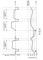
- FIG. 6 shows an example of a charging and discharging schedule of a plurality of battery modules and temperature changes of a battery cell.
- a period of time (an electrified section) is provided for charging the battery modules MDL.
- this charging period it is preferable to perform charging at a high C-rate, since charging is completed in a relatively short period of time (e.g., five minutes), utilizing the period of time during which the railroad vehicle is stopping at the station.
- the temperature of the battery cell when the temperature of the battery cell is 15°C, the voltage of the battery cell reaches its upper limit at a low charging power, as compared to when the temperature of the battery cell is 25°C. That is, in order to fully charge a battery cell in a short period of time, at a high power, and at a high C-rate, it is desirable that the temperature of the battery cell be between, for example, 25°C and 45°C.
- the battery modules MDL are neither charged nor discharged in the period immediately before the railroad vehicle reaches the no-overhead-line section B.
- the temperature of the battery cell is low at the timing at which the railroad vehicle commences running through the no-overhead-line section B, as shown by, for example, the dashed line, the discharging power in the no-overhead-line section B is restricted, and a predetermined operation plan may not be accomplished.
- the battery temperature controller 12 computes a prediction value indicating a change over time of the SOC of the battery cell based on the operation plan, and determines whether or not there is a timing at which rapid discharging is performed (with the discharging power equal to or greater than a predetermined threshold value) and the SOC of the battery cell becomes equal to or lower than a predetermined value (step SA2).
- the temperature of the battery cell is controlled so as to fall within a predetermined range, at the commencement of rapid discharging.
- the battery temperature controller 12 sets the time of day for the commencement of the temperature control of the battery cell, taking the cooling and heating performance of the storage battery device into consideration (step SA3).
- the battery temperature controller 12 computes a prediction value indicating a change over time of the SOC of the battery cell based on the operation plan, and determines whether or not there is a timing at which rapid charging is performed (with the charging power equal to or greater than a predetermined threshold value) and the SOC of the battery cell becomes equal to or greater than a predetermined threshold value (step SA4).
- the temperature of the battery cell is controlled so as to fall within a predetermined range, at the commencement of rapid charging.
- the battery temperature controller 12 sets the time of day for the commencement of the temperature control of the battery cell, taking the cooling and heating performance of the storage battery device into consideration (step SA5).
- the battery temperature controller 12 may control the temperature of the battery cell according to the value of the SOC of the battery cell even when the C-rate is equal to or lower than a predetermined value.
- FIG. 7 is a flowchart illustrating an example of an operation of a battery temperature controller of a storage battery device according to an embodiment.
- the battery temperature controller 12 determines whether or not the time of day has arrived for the commencement of temperature control of battery cells (step SB1), and when it is determined that the time of day for the commencement has arrived, the temperature control of the battery cells is performed in such a manner that the internal resistance value of each of the battery cells falls within a predetermined range (step SB2).
- the battery temperature controller 12 acquires the temperature and the SOC of each of the battery cells (step SB21).
- the battery temperature controller 12 finds an internal resistance value of each of the battery cells by referring to a table of internal resistance values, each corresponding to the temperature and the SOC value of a battery cell (step SB22).
- FIG. 8 shows an example of a table storing internal resistance values, each corresponding to the temperature and the SOC of a battery cell.
- the battery temperature controller 12 is capable of reading, from the table, the corresponding internal resistance value of each of the battery cells, using the temperature of each of the battery cells received from the cell monitoring unit 2 and the computed SOC value.
- the value of the internal resistance of a battery cell varies according to the state of deterioration caused by, for example, the duration of use of the battery cell. Accordingly, in order to find more accurate internal resistance values, the battery temperature controller 12 may correct the values stored in the table based on the duration and history of use of the battery cells, and a table corresponding to each of the deterioration states may be provided.
- the battery temperature controller 12 determines whether or not the internal resistance values of the battery cells fall within a predetermined range (step SB23). At this time, the battery temperature controller 12 may determine whether or not both the largest value and the smallest value among the internal resistance values are included in a predetermined range, or whether or not a mean value of the internal resistance values of the battery cells is included in a predetermined range.
- the battery temperature controller 12 adjusts the temperature of the medium (step SB24). That is, when it is determined that the internal resistance value of each of the battery cells is equal to or greater than a predetermined threshold value, the battery temperature controller 12 outputs a temperature instruction to the heater 24 of the heating unit 20 to increase the temperature of the medium. If it is determined that the internal resistance value of each of the battery cells is equal to or lower than a predetermined threshold value, the battery temperature controller 12 outputs a temperature instruction to the cooling unit 30 to decrease the temperature of the medium.
- the battery temperature controller 12 adjusts the temperature of the medium, as described above, and controls the temperature of each of the battery cells in such a manner that the internal resistance value of each of the battery cells falls within a predetermined range, until the time of day for the commencement of rapid charging or discharging of the battery modules MDL comes.
- the battery temperature controller 12 may adjust the temperature of the medium to prevent the temperature of each of the battery cells from becoming equal to or greater than a threshold value, to preferentially suppress deterioration of the battery cells.
- the battery temperature controller 12 terminates the temperature control of the battery cells when the time of day for the commencement of rapid charging or discharging of the battery modules MDL has arrived (step SB3).
- the battery temperature controller 12 controls the heating unit 20 and the cooling unit 30 in such a manner that the temperature of each of the battery cells does not become equal to or greater than the permissible upper-limit value or the permissible lower-limit value, even during a period other than the period in which the temperature control based on the internal resistance values of the battery cells is performed, as described above, thereby preventing the temperature of each of the battery cells from becoming overly high or low.
- a period of time is provided for charging the battery modules MDL.
- temperature management is performed from the commencement of operation to the commencement of charging, by commencing operation after heating the battery cells in advance, as necessary, in such a manner that the internal resistance value of each of the battery cells falls within a predetermined range.
- the internal resistance of each of the battery cells at the commencement of charging falls within a predetermined range, and charging can be completed in a relatively short period of time.
- the battery modules MDL are neither charged nor discharged in the period immediately before the railroad vehicle reaches the no-overhead-line section B.
- the battery temperature controller 12 commences temperature control of the battery cells before the railroad vehicle runs through the no-overhead-line section B, in such a manner that the internal resistance of each of the battery cells falls within a predetermined range, at the timing at which the railroad vehicle commences running through the no-overhead-line section B. Thereby, the internal resistance of each of the battery cells at the commencement of discharging falls within a predetermined range, and feeding from the storage battery device can be performed while the vehicle is running through a no-overhead-line section.
- the point in time when the voltage of each of the battery cells may possibly exceed the upper-limit value or the lower-limit value can be known in advance when, for example, the operation plan is known in advance, as in the above-described case, it is possible to perform temperature control of the battery cells in such a manner that the internal resistance of each of the battery cells falls within a predetermined range at that point in time. It is thereby possible to optimize the use of the battery cells installed in the storage battery device at an SOC ranging from 0% to approximately full charge, and to improve the charging and discharging performance of the storage battery device, without increasing the number of the battery cells.
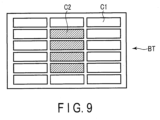
- FIG. 9 shows an example of the positions of arrangement of high-temperature battery cells and low-temperature battery cells in an assembled battery.
- FIG. 10 shows an example of the positions of arrangement of high-temperature battery cells and low-temperature battery cells in a battery module including a plurality of assembled batteries.
- low-temperature battery cells C1 and high-temperature battery cells C2 are included in an assembled battery BT.
- a battery module MDL including a single assembled battery BT for example, a battery cell arranged in a region surrounded by other battery cells tends to have a high temperature.
- a battery module MDL including a plurality of assembled batteries BT for example, a battery cell arranged inside, surrounded by a plurality of battery cells, tends to have a high temperature.
- temperature control of the battery cells is performed by focusing on the highest-temperature battery cell and the lowest-temperature battery cell in the battery module MDL.
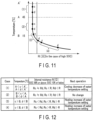
- FIG. 11 is a diagram illustrating an example of temperature control of battery cells in a storage battery device according to a second embodiment.
- A' first temperature threshold value
- a (second temperature threshold value) [°C] > B (third temperature threshold value)[°C] is satisfied, where, for example, A' denotes a permissible upper-limit temperature taking deterioration of the battery cells into account, A denotes an upper-limit temperature of the battery cells taking the internal resistance values of the battery cells into account, and B denotes a lower-limit temperature of the battery cells taking the internal resistance values of the battery cells into account.
- A' 55°C
- A 45°C
- B 15°C.
- the internal resistance of the highest-temperature battery cell is denoted by Rc
- the internal resistance of the lowest-temperature battery cell is denoted by Rd
- the target upper-limit value (upper-limit threshold value) of the internal resistance of the battery cell is denoted by R.
- battery cells at a temperature of B [°C] or above have a substantially equal internal resistance value, which is equal to or lower than the upper-limit threshold value R of the internal resistance value.
- the battery temperature controller 12 receives the temperature and the internal resistance value of each of the battery cells from the battery modules MDL, and selects the highest value and the lowest value among the received temperatures.
- FIG. 12 is a diagram illustrating an example of temperature control of the battery cells in the storage battery device according to the second embodiment.
- the battery temperature controller 12 lowers the temperature setting of the medium in such a manner that the temperature of each of the battery cells does not exceed the upper-limit temperature A' [°C], since charging and discharging of the battery cells at a high temperature causes the battery cells to deteriorate quickly.
- the battery temperature controller 12 similarly lowers the temperature setting of the medium in such a manner that the temperature of each of the battery cells does not exceed the upper-limit temperature A' [°C], since charging and discharging of the battery cells at a high temperature could cause the battery cells to deteriorate quickly.
- the battery temperature controller 12 outputs a temperature instruction to the cooling unit 30 to cool the medium in such a manner that the temperature of the medium falls below the value detected by the temperature detector TC when at least A ⁇ c ⁇ A' and Rd ⁇ R, thereby decreasing the temperature of each of the battery cells.
- the battery temperature controller 12 controls the heating unit 20 and the cooling unit 30 in such a manner that the temperature of the medium keeps the value detected by the temperature detector TC.
- the battery temperature controller 12 may output a temperature instruction to the heating unit 20 to increase the temperature of each of the battery cells.
- the temperature controller 12 controls the heating unit 20 and the cooling unit 30 in such a manner that the temperature of the medium keeps the value detected by the temperature detector TC when at least B ⁇ c ⁇ A and Rd ⁇ R.
- the battery temperature controller 12 since the internal resistance value of at least the lowest-temperature battery cell is above the upper-limit threshold value R, the battery temperature controller 12 outputs a temperature instruction to the heater 24 of the heating unit 20 to heat the medium in such a manner that the temperature of the medium rises above the value detected by the temperature detector TC, thereby increasing the temperature of each of the battery cells.
- the battery temperature controller 12 since the internal resistance values of all the battery cells are above the upper-limit threshold value R, the battery temperature controller 12 outputs a temperature instruction to the heater 24 of the heating unit 20 to heat the medium in such a manner that the temperature of the medium rises above the value detected by the temperature detector TC, thereby increasing the temperature of each of the battery cells.
- the battery temperature controller 12 may perform control in such a manner that the temperature of each of the battery cells increases in a short period of time, by increasing the amount of heat applied by the heater 24.
- the battery temperature controller 12 outputs a temperature instruction to the heater 24 of the heating unit 20 to heat the medium in such a manner that the temperature of the medium rises above the value detected by the temperature detector TC when at least d ⁇ B and Rd ⁇ R, thereby increasing the temperature of each of the battery cells.
- the storage battery device of the present embodiment differs from the first embodiment in terms of the operation of the temperature control (step SB2) of the battery cells. That is, the battery temperature controller 12 acquires the temperature and the SOC of each of the battery cells, as in step SB21, and finds an internal resistance value of each of the battery cells by referring to a table of internal resistance values, each corresponding to the temperature and the SOC value of a battery cell, as in step SB22. Thereafter, the battery temperature controller 12 determines which of cases (1)-(4) applies, based on the internal resistance value and the temperature of each of the battery cells, and performs temperature control of the battery cells according to the appropriate case.
- the storage battery device of the present embodiment it is possible to optimize the use of the battery cells installed in the storage battery device at an SOC ranging from 10% to approximately full charge, for example, and to improve the charging and discharging performance of the storage battery device, without increasing the number of the battery cells.
- a disaster for example, while a vehicle is running on power fed from overhead lines or a third rail and the feeding from the external source is stopped, it is necessary to move passengers to a safe place using the energy stored in the storage battery device.
- the storage battery device is discharged after temperature control is performed to make the internal resistance value of each of the battery cells fall within a predetermined range.
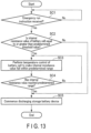
- FIG. 13 is a flowchart illustrating an example of an operation of a storage battery device according to a third embodiment.
- the upper-level control device When feeding from overhead lines or a third rail has stopped and the vehicle needs to make an emergency run, the upper-level control device transmits an emergency run instruction to the storage battery device.
- the battery temperature controller 12 Upon receiving an emergency run instruction (step SC1), the battery temperature controller 12 determines whether or not the internal resistance value of each of the battery cells received from the battery modules MDL falls within a predetermined range (step SC2).
- the battery temperature controller 12 commences discharging the storage battery device (step SC5).
- step SC3 the battery temperature controller 12 performs temperature control of the battery cells in such a manner that the internal resistance value falls within a predetermined range.
- the battery temperature controller 12 may perform temperature control of the battery cells based on the internal resistance value of each of the battery cells, as in the first embodiment (e.g, step S24), and may perform temperature control of the battery cells based on the internal resistance value and the temperature of each of the battery cells, as in the second embodiment.
- the upper-limit value and the lower-limit value for the internal resistance values during an emergency run may differ from the upper-limit value and the lower-limit value during a normal run. Since temperature control is performed by, for example, controlling the heating unit 20 and the cooling unit 30 using the energy stored in the assembled battery BT, when there is a possibility that using too much energy for temperature control may cause a lack of energy to be used for a run, the upper-limit value and the lower-limit value may be adjusted in such a manner that more energy can be used for a run.
- the battery temperature controller 12 performs temperature control of the battery cells until the internal resistance value of each of the battery cells reaches a predetermined range, and when the internal resistance value of each of the battery cells reaches the predetermined range (step SC4), the battery temperature controller 12 commences discharging the storage battery device (step SC5).
- FIG. 14 shows an example of charging and discharging power of a plurality of battery modules and temperature changes of a battery cell.
- the C-rate increases during discharging.
- the temperature of each of the battery cells may become substantially equal to the outer temperature, and there is a good likelihood that the temperature of each of the battery cells decreases to a level as low as 10°C or below.
- the temperature of the battery cells is 10°C, there is a possibility that an amount of power required for the vehicle to climb up an upward slope may not be discharged, due to the low temperature of the battery cells.
- the battery temperature controller 12 heats the battery cells in such a manner that the internal resistance of each of the battery cells falls within a predetermined range, at the position where the external power supply has stopped, causing the vehicle to be stopped.
- the battery temperature controller 12 confirms that the internal resistance has been lowered, and commences discharging the storage battery device.
- the vehicle is capable of running through a section in which each battery cell is assigned a heavy load for discharging, optimizing the use of the energy stored in the storage battery device, thus allowing the vehicle to run to the next station and drop off the passengers at a safe place.
- the storage battery device of the present embodiment it is possible to optimize the use of the battery cells installed in the storage battery device at an SOC ranging from approximately 10% to approximately full charge, for example, and to improve the charging and discharging performance of the storage battery device, without increasing the number of battery cells.
- examples have been described of a storage battery device installed in a railroad vehicle; however, applications of the storage battery device are not limited to railroad vehicles, and include other vehicles in which a storage battery device is installed.
- the operation shown in FIG. 5 may be omitted, and the temperature control by the battery temperature controller 12 based on the internal resistance value of each of the battery cells may be performed prior to the commencement of feeding from the storage battery device, during feeding from the storage battery device, and during charging of the storage battery device.
- the internal resistance value of each of the battery cells is found using a table of internal resistance values, each corresponding to the temperature and the SOC of a battery cell; however, it is also possible to use an internal resistance value detected by a detector included in the cell monitoring unit 2 or the battery management unit 10, or to use a polynominal for an internal resistance value corresponding to the SOC and the temperature of each of the battery cells.
- an estimated value is often used that is calculated by the battery management unit 10 based on values such as the voltage and temperature of each of the battery cells and the current of the assembled battery BT.
- the internal resistance value of each of the battery cells obtained based on the estimated value of the SOC may have a lower degree of precision than an internal resistance value detected by a detector.
- the temperature control of the battery cells can be performed with higher precision by directly measuring the internal resistance value.
Landscapes
- Chemical & Material Sciences (AREA)
- Chemical Kinetics & Catalysis (AREA)
- Electrochemistry (AREA)
- General Chemical & Material Sciences (AREA)
- Engineering & Computer Science (AREA)
- Manufacturing & Machinery (AREA)
- General Physics & Mathematics (AREA)
- Physics & Mathematics (AREA)
- Secondary Cells (AREA)
- Algebra (AREA)
- Mathematical Analysis (AREA)
- Mathematical Optimization (AREA)
- Pure & Applied Mathematics (AREA)
- Mechanical Engineering (AREA)
- Automation & Control Theory (AREA)
- Charge And Discharge Circuits For Batteries Or The Like (AREA)
- Electric Propulsion And Braking For Vehicles (AREA)
Claims (3)
- Verfahren zum Betreiben einer Speicherbatterievorrichtung, die in einem Schienenfahrzeug installiert ist, wobei:die Speicherbatterievorrichtung mindestens ein Batteriemodul (MDL), das eine zusammengesetzte Batterie (BT) umfasst, die mehrere Batteriezellen, eine Zellenüberwachungseinheit (2), die eine Spannung und eine Temperatur jeder der Batteriezellen detektiert, und eine Temperatureinstelleinheit (4), die die Temperatur jeder der Batteriezellen einstellt, enthält;eine Heizeinheit (20), die ein Medium erwärmt, das der Temperatureinstelleinheit (4) zugeführt wird, und das erwärmte Medium ausgibt;eine Kühleinheit (30), die das Medium, das der Temperatureinstelleinheit (4) zugeführt wird, kühlt und das gekühlte Medium ausgibt; undeine Batteriemanagementeinheit (10), die einen Temperaturdetektor (TC) und eine Batterietemperatur-Steuereinheit (12) enthält, wobei der Temperaturdetektor (TC) konfiguriert ist, mit der Zellenüberwachungseinheit (2) und mit der äußeren Umgebung zu kommunizieren und eine Temperatur des Mediums zu detektieren, wobei die Batterietemperatur-Steuereinheit (12) eine Temperatursteuerung der Batteriezellen durchführt, indem die Heizeinheit (20) und die Kühleinheit (30) unter Verwendung der Temperatur des Mediums, die durch den Temperaturdetektor (TC) detektiert wird, eines berechneten Batterieladezustands jeder der Batteriezellen und der Spannung und der Temperatur jeder der Batteriezellen, die von der Zellenüberwachungseinheit (2) des Batteriemoduls (MDL) empfangen werden, gesteuert werden, um eine Temperatur des Mediums einzustellen, umfasst,wobei das Verfahren Folgendes umfasst:- Empfangen eines Arbeitsplans des Schienenfahrzeugs für einen vorgegebenen Zeitraum von außerhalb und- Berechnen eines Vorhersagewertes, der eine Änderung im Zeitablauf des Batterieladezustands der Batteriezelle angibt, auf der Grundlage des Arbeitsplans,um auf der Grundlage des Arbeitsplans eine Tageszeit zum Durchführen der Temperatursteuerung der Batteriezellen einzustellen und die Temperatursteuerung der Batteriezellen durchzuführen.
- Verfahren nach Anspruch 1, wobei die Batterietemperatur-Steuereinheit (12):die Kühleinheit (30) derart steuert, dass das Medium gekühlt wird und die Temperatur jeder der Batteriezellen herabgesetzt wird, wenn ein höchster Wert der Temperaturen der Batteriezellen, die von der Zellenüberwachungseinheit (2) empfangen werden, unter einem ersten Temperaturschwellenwert und über einem zweiten Temperaturschwellenwert liegt und ein Wert des inneren Widerstands einer Batteriezelle, die eine Temperatur mit einem niedrigsten Wert von den Temperaturen der Batteriezellen aufweist, unter einem oberen Grenzschwellenwert für den Wert des inneren Widerstands liegt;die Temperatur jeder der Batteriezellen aufrechterhält, wenn der höchste Wert über einem dritten Temperaturschwellenwert und unter dem zweiten Temperaturschwellenwert liegt und der Wert des inneren Widerstands der Batteriezelle, die die Temperatur mit dem niedrigsten Wert aufweist, unter dem oberen Grenzschwellenwert für den Wert des inneren Widerstands liegt; unddie Heizeinheit (20) derart steuert, dass das Medium erwärmt wird und die Temperatur von jeder der Batteriezellen erhöht wird, wenn der niedrigste Wert unter dem dritten Temperaturschwellenwert liegt und der Wert des inneren Widerstands der Batteriezelle, die die Temperatur mit dem niedrigsten Wert aufweist, größer oder gleich dem oberen Grenzschwellenwert für den Wert des inneren Widerstands ist.
- Verfahren nach Anspruch 1 oder 2, wobei die Batterietemperatur-Steuereinheit (12) die Temperatursteuerung der Batteriezellen in der Weise durchführt, dass der Wert des inneren Widerstand jeder der Batteriezellen in einen vorgegebenen Bereich fällt, wenn eine Notfallablaufanweisung empfangen wird und der Wert des inneren Widerstands jeder der Batteriezellen größer oder gleich einem vorgegebenen Schwellenwert ist, und das Entladen beginnt, wenn der Wert des inneren Widerstands jeder der Batteriezellen in den vorgegebenen Bereich abgefallen ist.
Applications Claiming Priority (1)
| Application Number | Priority Date | Filing Date | Title |
|---|---|---|---|
| JP2018190930A JP2020061244A (ja) | 2018-10-09 | 2018-10-09 | 蓄電池装置 |
Publications (2)
| Publication Number | Publication Date |
|---|---|
| EP3637533A1 EP3637533A1 (de) | 2020-04-15 |
| EP3637533B1 true EP3637533B1 (de) | 2025-01-29 |
Family
ID=68242317
Family Applications (1)
| Application Number | Title | Priority Date | Filing Date |
|---|---|---|---|
| EP19201928.9A Active EP3637533B1 (de) | 2018-10-09 | 2019-10-08 | Verfahren zum betreiben einer speicherbatterievorrichtung |
Country Status (3)
| Country | Link |
|---|---|
| EP (1) | EP3637533B1 (de) |
| JP (1) | JP2020061244A (de) |
| CN (1) | CN111030206A (de) |
Families Citing this family (10)
| Publication number | Priority date | Publication date | Assignee | Title |
|---|---|---|---|---|
| CN113690514B (zh) * | 2020-05-19 | 2024-03-19 | 比亚迪股份有限公司 | 一种电池温度控制方法、装置、设备及介质 |
| CN111458651A (zh) * | 2020-05-25 | 2020-07-28 | 杭叉集团股份有限公司 | 电池充放电测试系统 |
| JP7527897B2 (ja) * | 2020-09-02 | 2024-08-05 | 株式会社東芝 | 二次電池および制御方法 |
| US11870047B2 (en) * | 2020-11-16 | 2024-01-09 | Ford Global Technologies, Llc | Traction battery thermal management |
| CN112666484B (zh) * | 2021-01-15 | 2022-11-08 | 湖南汽车工程职业学院 | 新能源汽车电池防寒防冻性能检测装置 |
| CN112952940A (zh) * | 2021-02-07 | 2021-06-11 | 中国第一汽车股份有限公司 | 高压充电系统和高压充电系统的充电方法 |
| CN114069094A (zh) * | 2021-10-29 | 2022-02-18 | 摩拜(北京)信息技术有限公司 | 电动自行车的电池包温度管理系统、方法和电动自行车 |
| CN118541849A (zh) | 2022-01-17 | 2024-08-23 | 松下知识产权经营株式会社 | 电源系统、加温控制方法以及加温控制程序 |
| CN115733209A (zh) * | 2022-11-07 | 2023-03-03 | 苏州融硅新能源科技有限公司 | 电池系统的控制方法、电池系统及电池管理系统 |
| CN118825503B (zh) * | 2024-09-10 | 2025-02-21 | 河南工学院 | 一种新能源电池簇的联动温度控制系统 |
Citations (2)
| Publication number | Priority date | Publication date | Assignee | Title |
|---|---|---|---|---|
| JP2017045700A (ja) * | 2015-08-28 | 2017-03-02 | 株式会社Ihi | バッテリー装置及び鉄道車両 |
| EP3703991B1 (de) * | 2017-12-19 | 2023-08-23 | Siemens Mobility GmbH | Spurgebundenes fahrzeug, anordnung zur kühlung einer energiespeichereinrichtung des spurgebundenen fahrzeugs sowie verfahren zur steuerung der anordnung |
Family Cites Families (7)
| Publication number | Priority date | Publication date | Assignee | Title |
|---|---|---|---|---|
| JP5434749B2 (ja) * | 2010-03-31 | 2014-03-05 | 株式会社デンソー | 電池制御システムおよびその制御方法 |
| JP2012016078A (ja) * | 2010-06-29 | 2012-01-19 | Hitachi Ltd | 充電制御システム |
| DE102011103974A1 (de) * | 2011-06-10 | 2012-12-13 | Daimler Ag | Verfahren und Vorrichtung zum Betrieb elektrochemischer Batterien |
| JP6555459B2 (ja) * | 2013-10-31 | 2019-08-07 | 三菱自動車工業株式会社 | 電池劣化監視システム |
| US9893394B2 (en) * | 2014-04-01 | 2018-02-13 | The Regents Of The University Of Michigan | Real-time battery thermal management for electric vehicles |
| US10099562B2 (en) * | 2014-10-15 | 2018-10-16 | Johnson Controls Technology Company | Cooling strategy for battery systems |
| JP2016082677A (ja) * | 2014-10-15 | 2016-05-16 | トヨタ自動車株式会社 | 車両の電源装置 |
-
2018
- 2018-10-09 JP JP2018190930A patent/JP2020061244A/ja active Pending
-
2019
- 2019-10-08 EP EP19201928.9A patent/EP3637533B1/de active Active
- 2019-10-09 CN CN201910952783.6A patent/CN111030206A/zh active Pending
Patent Citations (2)
| Publication number | Priority date | Publication date | Assignee | Title |
|---|---|---|---|---|
| JP2017045700A (ja) * | 2015-08-28 | 2017-03-02 | 株式会社Ihi | バッテリー装置及び鉄道車両 |
| EP3703991B1 (de) * | 2017-12-19 | 2023-08-23 | Siemens Mobility GmbH | Spurgebundenes fahrzeug, anordnung zur kühlung einer energiespeichereinrichtung des spurgebundenen fahrzeugs sowie verfahren zur steuerung der anordnung |
Also Published As
| Publication number | Publication date |
|---|---|
| CN111030206A (zh) | 2020-04-17 |
| EP3637533A1 (de) | 2020-04-15 |
| JP2020061244A (ja) | 2020-04-16 |
Similar Documents
| Publication | Publication Date | Title |
|---|---|---|
| EP3637533B1 (de) | Verfahren zum betreiben einer speicherbatterievorrichtung | |
| KR101846632B1 (ko) | 연료전지차량의 스탑모드시 전압 제어방법 | |
| RU2696610C2 (ru) | Способ и устройство для ограничения тока аккумулятора электрической энергии в зависимости от температуры | |
| US9227524B2 (en) | Electric-powered vehicle | |
| US10086718B2 (en) | System and method for operating a battery pack | |
| US7755329B2 (en) | Battery charging time optimization system based on battery temperature, cooling system power demand, and availability of surplus external power | |
| JP5378023B2 (ja) | 車両用電源装置及びその冷却方法 | |
| US20140097787A1 (en) | Active battery management system for a battery pack | |
| EP4018537A1 (de) | Systeme und verfahren zur batterievorwärmung bei einem hybriden elektrischen antriebsstrang eines flugzeuges | |
| KR102418517B1 (ko) | Soc-soh기반 선박 배터리 제어 관리 시스템 | |
| US20080084182A1 (en) | Lithium battery system | |
| WO2016083529A1 (en) | Method of operating a battery in an electrically powered vehicle | |
| CA2911036A1 (en) | Large electric vehicle power structure and alternating-hibernation battery management and control method thereof | |
| KR20100040745A (ko) | 전력 저장 시스템 | |
| KR102742036B1 (ko) | 배터리 전력 산출 장치 및 방법 | |
| CN102457078A (zh) | 电池均衡电路、电池均衡系统及方法 | |
| JP6516525B2 (ja) | 蓄電システム | |
| US20250038559A1 (en) | Systems and methods for adaptive electrochemical cell management | |
| JP2019057455A (ja) | 二次電池の制御装置および制御方法 | |
| EP4480061A1 (de) | Verwaltung von batteriepacks | |
| JP2021170883A (ja) | 蓄電システム | |
| JP2008092656A (ja) | 車両用の電源装置 | |
| US20050137823A1 (en) | Battery overtemperature control system and method | |
| KR20220054485A (ko) | 전기 자동차용 배터리 온도 조절 장치 | |
| JP6221697B2 (ja) | 電圧差補正装置、電圧差補正プログラムならびに方法 |
Legal Events
| Date | Code | Title | Description |
|---|---|---|---|
| PUAI | Public reference made under article 153(3) epc to a published international application that has entered the european phase |
Free format text: ORIGINAL CODE: 0009012 |
|
| STAA | Information on the status of an ep patent application or granted ep patent |
Free format text: STATUS: REQUEST FOR EXAMINATION WAS MADE |
|
| 17P | Request for examination filed |
Effective date: 20191008 |
|
| AK | Designated contracting states |
Kind code of ref document: A1 Designated state(s): AL AT BE BG CH CY CZ DE DK EE ES FI FR GB GR HR HU IE IS IT LI LT LU LV MC MK MT NL NO PL PT RO RS SE SI SK SM TR |
|
| AX | Request for extension of the european patent |
Extension state: BA ME |
|
| STAA | Information on the status of an ep patent application or granted ep patent |
Free format text: STATUS: EXAMINATION IS IN PROGRESS |
|
| 17Q | First examination report despatched |
Effective date: 20210901 |
|
| GRAP | Despatch of communication of intention to grant a patent |
Free format text: ORIGINAL CODE: EPIDOSNIGR1 |
|
| STAA | Information on the status of an ep patent application or granted ep patent |
Free format text: STATUS: GRANT OF PATENT IS INTENDED |
|
| RIC1 | Information provided on ipc code assigned before grant |
Ipc: H01M 50/569 20210101ALI20240911BHEP Ipc: B60R 16/033 20060101ALI20240911BHEP Ipc: H01M 10/656 20140101ALI20240911BHEP Ipc: H01M 10/651 20140101ALI20240911BHEP Ipc: H01M 10/63 20140101ALI20240911BHEP Ipc: H01M 10/615 20140101ALI20240911BHEP Ipc: H01M 10/613 20140101ALI20240911BHEP Ipc: H01M 10/48 20060101ALI20240911BHEP Ipc: H01M 10/44 20060101ALI20240911BHEP Ipc: H01M 10/42 20060101AFI20240911BHEP |
|
| INTG | Intention to grant announced |
Effective date: 20240927 |
|
| GRAS | Grant fee paid |
Free format text: ORIGINAL CODE: EPIDOSNIGR3 |
|
| GRAA | (expected) grant |
Free format text: ORIGINAL CODE: 0009210 |
|
| STAA | Information on the status of an ep patent application or granted ep patent |
Free format text: STATUS: THE PATENT HAS BEEN GRANTED |
|
| AK | Designated contracting states |
Kind code of ref document: B1 Designated state(s): AL AT BE BG CH CY CZ DE DK EE ES FI FR GB GR HR HU IE IS IT LI LT LU LV MC MK MT NL NO PL PT RO RS SE SI SK SM TR |
|
| REG | Reference to a national code |
Ref country code: GB Ref legal event code: FG4D |
|
| REG | Reference to a national code |
Ref country code: CH Ref legal event code: EP |
|
| REG | Reference to a national code |
Ref country code: DE Ref legal event code: R096 Ref document number: 602019065336 Country of ref document: DE |
|
| REG | Reference to a national code |
Ref country code: IE Ref legal event code: FG4D |
|
| REG | Reference to a national code |
Ref country code: NL Ref legal event code: MP Effective date: 20250129 |
|
| PG25 | Lapsed in a contracting state [announced via postgrant information from national office to epo] |
Ref country code: NL Free format text: LAPSE BECAUSE OF FAILURE TO SUBMIT A TRANSLATION OF THE DESCRIPTION OR TO PAY THE FEE WITHIN THE PRESCRIBED TIME-LIMIT Effective date: 20250129 |
|
| PG25 | Lapsed in a contracting state [announced via postgrant information from national office to epo] |
Ref country code: RS Free format text: LAPSE BECAUSE OF FAILURE TO SUBMIT A TRANSLATION OF THE DESCRIPTION OR TO PAY THE FEE WITHIN THE PRESCRIBED TIME-LIMIT Effective date: 20250429 |
|
| PG25 | Lapsed in a contracting state [announced via postgrant information from national office to epo] |
Ref country code: FI Free format text: LAPSE BECAUSE OF FAILURE TO SUBMIT A TRANSLATION OF THE DESCRIPTION OR TO PAY THE FEE WITHIN THE PRESCRIBED TIME-LIMIT Effective date: 20250129 |
|
| PG25 | Lapsed in a contracting state [announced via postgrant information from national office to epo] |
Ref country code: PL Free format text: LAPSE BECAUSE OF FAILURE TO SUBMIT A TRANSLATION OF THE DESCRIPTION OR TO PAY THE FEE WITHIN THE PRESCRIBED TIME-LIMIT Effective date: 20250129 |
|
| PG25 | Lapsed in a contracting state [announced via postgrant information from national office to epo] |
Ref country code: ES Free format text: LAPSE BECAUSE OF FAILURE TO SUBMIT A TRANSLATION OF THE DESCRIPTION OR TO PAY THE FEE WITHIN THE PRESCRIBED TIME-LIMIT Effective date: 20250129 |
|
| REG | Reference to a national code |
Ref country code: LT Ref legal event code: MG9D |
|
| PG25 | Lapsed in a contracting state [announced via postgrant information from national office to epo] |
Ref country code: IS Free format text: LAPSE BECAUSE OF FAILURE TO SUBMIT A TRANSLATION OF THE DESCRIPTION OR TO PAY THE FEE WITHIN THE PRESCRIBED TIME-LIMIT Effective date: 20250529 Ref country code: NO Free format text: LAPSE BECAUSE OF FAILURE TO SUBMIT A TRANSLATION OF THE DESCRIPTION OR TO PAY THE FEE WITHIN THE PRESCRIBED TIME-LIMIT Effective date: 20250429 |
|
| REG | Reference to a national code |
Ref country code: AT Ref legal event code: MK05 Ref document number: 1764398 Country of ref document: AT Kind code of ref document: T Effective date: 20250129 |
|
| PG25 | Lapsed in a contracting state [announced via postgrant information from national office to epo] |
Ref country code: HR Free format text: LAPSE BECAUSE OF FAILURE TO SUBMIT A TRANSLATION OF THE DESCRIPTION OR TO PAY THE FEE WITHIN THE PRESCRIBED TIME-LIMIT Effective date: 20250129 |
|
| PG25 | Lapsed in a contracting state [announced via postgrant information from national office to epo] |
Ref country code: PT Free format text: LAPSE BECAUSE OF FAILURE TO SUBMIT A TRANSLATION OF THE DESCRIPTION OR TO PAY THE FEE WITHIN THE PRESCRIBED TIME-LIMIT Effective date: 20250529 Ref country code: LV Free format text: LAPSE BECAUSE OF FAILURE TO SUBMIT A TRANSLATION OF THE DESCRIPTION OR TO PAY THE FEE WITHIN THE PRESCRIBED TIME-LIMIT Effective date: 20250129 |
|
| PG25 | Lapsed in a contracting state [announced via postgrant information from national office to epo] |
Ref country code: GR Free format text: LAPSE BECAUSE OF FAILURE TO SUBMIT A TRANSLATION OF THE DESCRIPTION OR TO PAY THE FEE WITHIN THE PRESCRIBED TIME-LIMIT Effective date: 20250430 Ref country code: BG Free format text: LAPSE BECAUSE OF FAILURE TO SUBMIT A TRANSLATION OF THE DESCRIPTION OR TO PAY THE FEE WITHIN THE PRESCRIBED TIME-LIMIT Effective date: 20250129 |
|
| PG25 | Lapsed in a contracting state [announced via postgrant information from national office to epo] |
Ref country code: AT Free format text: LAPSE BECAUSE OF FAILURE TO SUBMIT A TRANSLATION OF THE DESCRIPTION OR TO PAY THE FEE WITHIN THE PRESCRIBED TIME-LIMIT Effective date: 20250129 |
|
| PG25 | Lapsed in a contracting state [announced via postgrant information from national office to epo] |
Ref country code: SE Free format text: LAPSE BECAUSE OF FAILURE TO SUBMIT A TRANSLATION OF THE DESCRIPTION OR TO PAY THE FEE WITHIN THE PRESCRIBED TIME-LIMIT Effective date: 20250129 |
|
| RAP2 | Party data changed (patent owner data changed or rights of a patent transferred) |
Owner name: KABUSHIKI KAISHA TOSHIBA |
|
| PG25 | Lapsed in a contracting state [announced via postgrant information from national office to epo] |
Ref country code: SM Free format text: LAPSE BECAUSE OF FAILURE TO SUBMIT A TRANSLATION OF THE DESCRIPTION OR TO PAY THE FEE WITHIN THE PRESCRIBED TIME-LIMIT Effective date: 20250129 |
|
| PG25 | Lapsed in a contracting state [announced via postgrant information from national office to epo] |
Ref country code: DK Free format text: LAPSE BECAUSE OF FAILURE TO SUBMIT A TRANSLATION OF THE DESCRIPTION OR TO PAY THE FEE WITHIN THE PRESCRIBED TIME-LIMIT Effective date: 20250129 |
|
| PG25 | Lapsed in a contracting state [announced via postgrant information from national office to epo] |
Ref country code: IT Free format text: LAPSE BECAUSE OF FAILURE TO SUBMIT A TRANSLATION OF THE DESCRIPTION OR TO PAY THE FEE WITHIN THE PRESCRIBED TIME-LIMIT Effective date: 20250129 |
|
| PG25 | Lapsed in a contracting state [announced via postgrant information from national office to epo] |
Ref country code: EE Free format text: LAPSE BECAUSE OF FAILURE TO SUBMIT A TRANSLATION OF THE DESCRIPTION OR TO PAY THE FEE WITHIN THE PRESCRIBED TIME-LIMIT Effective date: 20250129 Ref country code: CZ Free format text: LAPSE BECAUSE OF FAILURE TO SUBMIT A TRANSLATION OF THE DESCRIPTION OR TO PAY THE FEE WITHIN THE PRESCRIBED TIME-LIMIT Effective date: 20250129 |
|
| PG25 | Lapsed in a contracting state [announced via postgrant information from national office to epo] |
Ref country code: RO Free format text: LAPSE BECAUSE OF FAILURE TO SUBMIT A TRANSLATION OF THE DESCRIPTION OR TO PAY THE FEE WITHIN THE PRESCRIBED TIME-LIMIT Effective date: 20250129 |
|
| PG25 | Lapsed in a contracting state [announced via postgrant information from national office to epo] |
Ref country code: SK Free format text: LAPSE BECAUSE OF FAILURE TO SUBMIT A TRANSLATION OF THE DESCRIPTION OR TO PAY THE FEE WITHIN THE PRESCRIBED TIME-LIMIT Effective date: 20250129 |
|
| REG | Reference to a national code |
Ref country code: DE Ref legal event code: R097 Ref document number: 602019065336 Country of ref document: DE |
|
| PLBE | No opposition filed within time limit |
Free format text: ORIGINAL CODE: 0009261 |
|
| STAA | Information on the status of an ep patent application or granted ep patent |
Free format text: STATUS: NO OPPOSITION FILED WITHIN TIME LIMIT |
|
| 26N | No opposition filed |
Effective date: 20251030 |