EP3637501A1 - Bus bar assembly for electrode lead bonding and battery module including same - Google Patents
Bus bar assembly for electrode lead bonding and battery module including same Download PDFInfo
- Publication number
- EP3637501A1 EP3637501A1 EP18866237.3A EP18866237A EP3637501A1 EP 3637501 A1 EP3637501 A1 EP 3637501A1 EP 18866237 A EP18866237 A EP 18866237A EP 3637501 A1 EP3637501 A1 EP 3637501A1
- Authority
- EP
- European Patent Office
- Prior art keywords
- bus bar
- pair
- movable
- fixed
- bar assembly
- Prior art date
- Legal status (The legal status is an assumption and is not a legal conclusion. Google has not performed a legal analysis and makes no representation as to the accuracy of the status listed.)
- Granted
Links
Images


Classifications
-
- H—ELECTRICITY
- H01—ELECTRIC ELEMENTS
- H01R—ELECTRICALLY-CONDUCTIVE CONNECTIONS; STRUCTURAL ASSOCIATIONS OF A PLURALITY OF MUTUALLY-INSULATED ELECTRICAL CONNECTING ELEMENTS; COUPLING DEVICES; CURRENT COLLECTORS
- H01R4/00—Electrically-conductive connections between two or more conductive members in direct contact, i.e. touching one another; Means for effecting or maintaining such contact; Electrically-conductive connections having two or more spaced connecting locations for conductors and using contact members penetrating insulation
- H01R4/02—Soldered or welded connections
- H01R4/029—Welded connections
-
- H—ELECTRICITY
- H01—ELECTRIC ELEMENTS
- H01M—PROCESSES OR MEANS, e.g. BATTERIES, FOR THE DIRECT CONVERSION OF CHEMICAL ENERGY INTO ELECTRICAL ENERGY
- H01M50/00—Constructional details or processes of manufacture of the non-active parts of electrochemical cells other than fuel cells, e.g. hybrid cells
- H01M50/50—Current conducting connections for cells or batteries
- H01M50/502—Interconnectors for connecting terminals of adjacent batteries; Interconnectors for connecting cells outside a battery casing
- H01M50/503—Interconnectors for connecting terminals of adjacent batteries; Interconnectors for connecting cells outside a battery casing characterised by the shape of the interconnectors
-
- H—ELECTRICITY
- H01—ELECTRIC ELEMENTS
- H01M—PROCESSES OR MEANS, e.g. BATTERIES, FOR THE DIRECT CONVERSION OF CHEMICAL ENERGY INTO ELECTRICAL ENERGY
- H01M50/00—Constructional details or processes of manufacture of the non-active parts of electrochemical cells other than fuel cells, e.g. hybrid cells
- H01M50/50—Current conducting connections for cells or batteries
- H01M50/502—Interconnectors for connecting terminals of adjacent batteries; Interconnectors for connecting cells outside a battery casing
- H01M50/507—Interconnectors for connecting terminals of adjacent batteries; Interconnectors for connecting cells outside a battery casing comprising an arrangement of two or more busbars within a container structure, e.g. busbar modules
-
- H—ELECTRICITY
- H01—ELECTRIC ELEMENTS
- H01M—PROCESSES OR MEANS, e.g. BATTERIES, FOR THE DIRECT CONVERSION OF CHEMICAL ENERGY INTO ELECTRICAL ENERGY
- H01M50/00—Constructional details or processes of manufacture of the non-active parts of electrochemical cells other than fuel cells, e.g. hybrid cells
- H01M50/50—Current conducting connections for cells or batteries
- H01M50/502—Interconnectors for connecting terminals of adjacent batteries; Interconnectors for connecting cells outside a battery casing
- H01M50/521—Interconnectors for connecting terminals of adjacent batteries; Interconnectors for connecting cells outside a battery casing characterised by the material
- H01M50/522—Inorganic material
-
- H—ELECTRICITY
- H01—ELECTRIC ELEMENTS
- H01M—PROCESSES OR MEANS, e.g. BATTERIES, FOR THE DIRECT CONVERSION OF CHEMICAL ENERGY INTO ELECTRICAL ENERGY
- H01M50/00—Constructional details or processes of manufacture of the non-active parts of electrochemical cells other than fuel cells, e.g. hybrid cells
- H01M50/50—Current conducting connections for cells or batteries
- H01M50/528—Fixed electrical connections, i.e. not intended for disconnection
-
- H—ELECTRICITY
- H01—ELECTRIC ELEMENTS
- H01R—ELECTRICALLY-CONDUCTIVE CONNECTIONS; STRUCTURAL ASSOCIATIONS OF A PLURALITY OF MUTUALLY-INSULATED ELECTRICAL CONNECTING ELEMENTS; COUPLING DEVICES; CURRENT COLLECTORS
- H01R4/00—Electrically-conductive connections between two or more conductive members in direct contact, i.e. touching one another; Means for effecting or maintaining such contact; Electrically-conductive connections having two or more spaced connecting locations for conductors and using contact members penetrating insulation
- H01R4/28—Clamped connections, spring connections
- H01R4/48—Clamped connections, spring connections utilising a spring, clip, or other resilient member
- H01R4/4809—Clamped connections, spring connections utilising a spring, clip, or other resilient member using a leaf spring to bias the conductor toward the busbar
- H01R4/48185—Clamped connections, spring connections utilising a spring, clip, or other resilient member using a leaf spring to bias the conductor toward the busbar adapted for axial insertion of a wire end
- H01R4/4819—Clamped connections, spring connections utilising a spring, clip, or other resilient member using a leaf spring to bias the conductor toward the busbar adapted for axial insertion of a wire end the spring shape allowing insertion of the conductor end when the spring is unbiased
- H01R4/4821—Single-blade spring
-
- H—ELECTRICITY
- H01—ELECTRIC ELEMENTS
- H01M—PROCESSES OR MEANS, e.g. BATTERIES, FOR THE DIRECT CONVERSION OF CHEMICAL ENERGY INTO ELECTRICAL ENERGY
- H01M50/00—Constructional details or processes of manufacture of the non-active parts of electrochemical cells other than fuel cells, e.g. hybrid cells
- H01M50/20—Mountings; Secondary casings or frames; Racks, modules or packs; Suspension devices; Shock absorbers; Transport or carrying devices; Holders
- H01M50/204—Racks, modules or packs for multiple batteries or multiple cells
- H01M50/207—Racks, modules or packs for multiple batteries or multiple cells characterised by their shape
- H01M50/211—Racks, modules or packs for multiple batteries or multiple cells characterised by their shape adapted for pouch cells
-
- H—ELECTRICITY
- H01—ELECTRIC ELEMENTS
- H01M—PROCESSES OR MEANS, e.g. BATTERIES, FOR THE DIRECT CONVERSION OF CHEMICAL ENERGY INTO ELECTRICAL ENERGY
- H01M50/00—Constructional details or processes of manufacture of the non-active parts of electrochemical cells other than fuel cells, e.g. hybrid cells
- H01M50/50—Current conducting connections for cells or batteries
- H01M50/502—Interconnectors for connecting terminals of adjacent batteries; Interconnectors for connecting cells outside a battery casing
- H01M50/514—Methods for interconnecting adjacent batteries or cells
- H01M50/516—Methods for interconnecting adjacent batteries or cells by welding, soldering or brazing
-
- H—ELECTRICITY
- H01—ELECTRIC ELEMENTS
- H01M—PROCESSES OR MEANS, e.g. BATTERIES, FOR THE DIRECT CONVERSION OF CHEMICAL ENERGY INTO ELECTRICAL ENERGY
- H01M50/00—Constructional details or processes of manufacture of the non-active parts of electrochemical cells other than fuel cells, e.g. hybrid cells
- H01M50/50—Current conducting connections for cells or batteries
- H01M50/531—Electrode connections inside a battery casing
- H01M50/536—Electrode connections inside a battery casing characterised by the method of fixing the leads to the electrodes, e.g. by welding
-
- H—ELECTRICITY
- H01—ELECTRIC ELEMENTS
- H01R—ELECTRICALLY-CONDUCTIVE CONNECTIONS; STRUCTURAL ASSOCIATIONS OF A PLURALITY OF MUTUALLY-INSULATED ELECTRICAL CONNECTING ELEMENTS; COUPLING DEVICES; CURRENT COLLECTORS
- H01R4/00—Electrically-conductive connections between two or more conductive members in direct contact, i.e. touching one another; Means for effecting or maintaining such contact; Electrically-conductive connections having two or more spaced connecting locations for conductors and using contact members penetrating insulation
- H01R4/28—Clamped connections, spring connections
- H01R4/48—Clamped connections, spring connections utilising a spring, clip, or other resilient member
- H01R4/4809—Clamped connections, spring connections utilising a spring, clip, or other resilient member using a leaf spring to bias the conductor toward the busbar
- H01R4/4846—Busbar details
-
- Y—GENERAL TAGGING OF NEW TECHNOLOGICAL DEVELOPMENTS; GENERAL TAGGING OF CROSS-SECTIONAL TECHNOLOGIES SPANNING OVER SEVERAL SECTIONS OF THE IPC; TECHNICAL SUBJECTS COVERED BY FORMER USPC CROSS-REFERENCE ART COLLECTIONS [XRACs] AND DIGESTS
- Y02—TECHNOLOGIES OR APPLICATIONS FOR MITIGATION OR ADAPTATION AGAINST CLIMATE CHANGE
- Y02E—REDUCTION OF GREENHOUSE GAS [GHG] EMISSIONS, RELATED TO ENERGY GENERATION, TRANSMISSION OR DISTRIBUTION
- Y02E60/00—Enabling technologies; Technologies with a potential or indirect contribution to GHG emissions mitigation
- Y02E60/10—Energy storage using batteries
Definitions
- the present disclosure relates to a bus bar assembly for joining an electrode lead and a battery module including the bus bar assembly, and more particularly, to a bus bar assembly capable of coupling electrode leads to a bus bar without bending the coupling electrode, and a battery module including the bus bar assembly.
- Secondary batteries currently commercialized include nickel cadmium batteries, nickel hydrogen batteries, nickel zinc batteries, lithium secondary batteries and so on.
- the lithium secondary batteries are more highlighted in comparison to nickel-based secondary batteries due to advantages such as free charging and discharging, caused by substantially no memory effect, very low self-discharge rate, and high energy density.
- the lithium secondary battery mainly uses lithium-based oxides and carbonaceous materials as a positive electrode active material and a negative electrode active material, respectively.
- the lithium secondary battery includes an electrode assembly in which a positive electrode plate coated with the positive electrode active material and a negative electrode plate coated with the negative electrode active material are disposed with a separator being interposed therebetween, and an exterior, namely a pouch exterior, sealably containing the electrode assembly together with an electrolyte.
- the lithium secondary battery may be classified into a can-type secondary battery in which an electrode assembly is included in a metal can and a pouch-type secondary battery in which an electrode assembly is included in a pouch made of an aluminum sheet, depending on the shape of the exterior.
- the electric vehicles include hybrid electric vehicles, plug-in hybrid electric vehicles, and pure electric vehicles powered only by an electric motor and a battery without an internal combustion engine.
- the secondary batteries When the secondary batteries are used in the electric vehicle, a large number of secondary batteries are electrically connected to increase capacity and power.
- pouch-type secondary batteries are widely used for the middle-sized or large-sized devices since they may be easily stacked.
- the battery module/pack of the middle-sized or large-sized device is implemented by connecting the pouch-type secondary batteries in series and/or in parallel.
- the bus bar is a rod-shaped conductor made of copper, silver, tin-plated copper or the like and having a rod shape.
- the bus bar may safely supply a large amount of current to the bus, compared to a copper wire, and thus the bus bar is widely used as a wiring member in a power supply device including a battery module of an electric vehicle.
- the present disclosure is designed to solve the problems of the related art, and therefore the present disclosure is directed to providing a bus bar assembly, which may coupling electrode leads to a bus bar without bending the electrode leads so that the electrode leads and the bus bar are adhered, and a battery module including the bus bar assembly.
- a bus bar assembly for electrically connecting a plurality of battery cells having electrode leads
- the bus bar assembly comprising: a fixed bus bar provided in the form of a rod-shaped conductor; a pair of movable bus bars disposed to be spaced from both sides of the fixed bus bar in a lateral direction with the fixed bus bar being interposed therebetween to form a fitting space respectively between the pair of movable bus bars and the fixed bus bar so that at least one electrode lead is inserted therein; and an adhering member configured to move the pair of movable bus bars close to the fixed bus bar in a state where the electrode lead is located in the fitting space so that the electrode lead is adhered to the fixed bus bar.
- Each of the pair of movable bus bars may include an adhering portion provided in parallel to the fixed bus bar and gap adjusting portions bent at both side ends of the adhering portion and extending therefrom, and the pair of movable bus bars may be disposed symmetric to each other with the fixed bus bar being interposed therebetween to surround a periphery of the fixed bus bar.
- the adhering member may be a leaf spring having both ends respectively coupled to the pair of movable bus bars to move the pair of movable bus bars in directions facing each other by means of an elastic restoration force.
- the leaf spring may be provided in a pair, and both ends of the pair of leaf springs may be coupled to end portions of the gap adjusting portions, which face each other at the pair of movable bus bars.
- the bus bar assembly may further comprise a bus bar support frame serving as a plate-shaped structure and having a slit formed at a location corresponding to the fitting space so that the electrode lead passes therethrough, the bus bar support frame supporting the pair of movable bus bars and the fixed bus bar so that the pair of movable bus bars are movable with respect to the fixed bus bar.
- a bus bar support frame serving as a plate-shaped structure and having a slit formed at a location corresponding to the fitting space so that the electrode lead passes therethrough, the bus bar support frame supporting the pair of movable bus bars and the fixed bus bar so that the pair of movable bus bars are movable with respect to the fixed bus bar.
- the bus bar support frame may include a gap keeping protrusion configured to be inserted between the gap adjusting portions of the pair of movable bus bars or released therefrom.
- the bus bar support frame may further include a cantilever beam having a free end located at the rear of the gap adjusting portion, and the gap keeping protrusion may be provided at the free end.
- the cantilever beam may further include a pressing protrusion protruding at a location spaced apart from the gap keeping protrusion.
- the bus bar support frame may further include corner brackets configured to surround and support four corner portions of the pair of movable bus bars in a state where the pair of movable bus bars are spaced farthest from both sides of the fixed bus bar in a lateral direction.
- a battery module comprising the bus bar assembly described above.
- the battery module may be used as an energy source of electric vehicles, hybrid electric vehicles or power storage devices.
- a bus bar assembly which may coupling electrode leads to a bus bar without bending the electrode leads so that the electrode leads and the bus bar are adhered, and a battery module including the bus bar assembly.
- the electrical connection and the mechanical bonding strength reliability may be improved regardless of the number of electrode leads in a parallel connection structure.
- the automation rate of the battery module production line may be improved.
- FIGS. 2 and 3 are perspective views schematically showing main components of a bus bar assembly according to an embodiment of the present disclosure and a battery cell stack.
- the bus bar assembly 1 is a bus bar assembly 1 for electrically connecting electrode leads 20 of a plurality of battery cells 10, and may include a fixed bus bar 100, a pair of movable bus bars 200, and an adhering member 300 for allowing relative movements of the pair of movable bus bars 200 relative to the fixed bus bar 100.
- the electrode lead 20 of the battery cell 10 includes a positive electrode lead 21 and a negative electrode lead 22.
- the positive electrode lead 21 and the negative electrode lead 22 are inserted directly into a fitting space S of the bus bar assembly 1 according to the present disclosure, and end portions of the positive electrode lead 21 and the negative electrode lead 22 may be clamped and then welded by the bus bar assembly 1.
- the electrode leads 20 may be welded under mechanical compression. Thus, even when two or more electrode leads 20 are joined in parallel, it is possible to maintain the reliability of electrical connection and the mechanical bonding strength.
- bus bar assembly 1 according to the present disclosure will be described in detail.
- the fixed bus bar 100 may be made of a rod-shaped material such as copper, silver, and tin-plated copper with electrical conductivity.
- the fixed bus bar 100 may allow safe passage of high capacity currents.
- the positive electrode leads 21 and the negative electrode leads 22 may be adhered and welded to the fixed bus bar and thus be electrically connected thereto.
- six battery cells 10 may be connected in total so that three battery cells are connected in parallel therein.
- the positive electrode leads of three battery cells are overlapped and the negative electrode leads of the other three battery cells are overlapped.
- end portions of the positive electrode leads and the negative electrode leads are inserted into the fitting space S, and then the end portions are adhered and welded to both side surfaces of the fixed bus bar 100 so as to be electrically connected thereto.
- the pair of movable bus bars 200 may be made of a metal such as copper, silver, tin plating, or copper with electrical conductivity, similar to the fixed bus bar 100.
- the pair of movable bus bars 200 may be spaced apart from both sides of the fixed bus bar 100 with the fixed bus bar 100 being interposed therebetween, thereby forming the fitting space S respectively between the pair of movable bus bars 200 and the fixed bus bar 100. That is, the fitting space S is formed at two places at both sides of the fixed bus bar 100.
- the pair of movable bus bars 200 may be provided so as to be movable in the horizontal direction with respect to the fixed bus bar 100.
- the pair of movable bus bars 200 may be disposed to be spaced apart from both sides of the fixed bus bar 100 as shown in FIG. 2 and move closer to the fixed bus bar 100 as shown in FIG. 3 .
- the width of the fitting space S may be adjusted according to the horizontal movement of the pair of movable bus bars 200, and the electrode leads 20 inserted in this fitting space S may mechanically compressed by the fixed bus bar 100 and the pair of movable bus bars 200.
- the movable bus bar 200 of this embodiment may include an adhering portion 210 and gap adjusting portions 220 in an approximately "c" shape.
- the adhering portion 210 may be defined as a portion disposed in parallel with the fixed bus bar 100, and the gap adjusting portions 220 may be defined as portions extending from the both side ends of the adhering portion 210 toward the fixed bus bar 100.
- the movable bus bar 200 is provided in a pair, and the pair of movable bus bars 200 may be disposed symmetrically to each other with the fixed bus bar 100 being interposed therebetween to surround a periphery of the fixed bus bar 100.
- the fitting spaces S may be formed between the two adhering portions 210 and both sides of the fixed bus bar 100, so that the gap adjusting portion 220 of one movable bus bar 200 may be in contact with the gap adjusting portion 220 of the other movable bus bar 200.
- the pair of movable bus bars 200 may be electrically connected to each other.
- the width of the fitting space S may be determined according to the length of the gap adjusting portion 220.
- the movable bus bar 200 is configured to form the fitting space S and press the electrode lead 20, so the movable bus bar 200 may not necessarily be made of an electrically conductive material. That is, since the positive electrode leads 21 and the negative electrode leads 22 may be sufficiently electrically connected using the fixed bus bar 100, the movable bus bar 200 may be made of an insulating material, different from the fixed bus bar 100. If the movable bus bar 200 is made of an insulating material as an alternative embodiment, a better effect may be obtained in preventing an electrical short circuit inside the battery module.
- the adhering member 300 moves the pair of movable bus bars 200 close to the fixed bus bar 100 so that the electrode lead 20 is adhered to the fixed bus bar 100.
- the adhering member 300 of this embodiment may be a leaf spring 300 that has both ends respectively coupled to the pair of movable bus bars 200 to move the pair of movable bus bars 200 in directions facing each other by means of an elastic restoration force.
- the leaf spring 300 may be coupled to the gap adjusting portion 220 of the movable bus bar 200.
- one end of the leaf spring 300 may be coupled to the movable bus bar 200 at the left side, and the other end of the leaf spring 300 may be coupled to the movable bus bar 200 at the right side.
- the leaf spring 300 is provided in a pair, and both ends of the pair of leaf springs 300 may be coupled to the end portions of the gap adjusting portions 220, which are respectively located at the upper and lower portions of the fixed bus bar 100 and face each other.
- the leaf spring 300 is in a widened state due to an external force. However, if the external force disappears as shown in FIG. 3 , the leaf spring 300 returns to the original state by means of the elastic restoration force.
- the movable bus bar 200 may move close to the fixed bus bar 100 by the above operation of the leaf spring 300.
- FIG. 4 is a perspective view showing a bus bar support frame according to an embodiment of the present disclosure
- FIGS. 5 and 6 are a perspective view and an enlarged view showing the bus bar assembly according to an embodiment of the present disclosure before the electrode leads are inserted
- FIGS. 7 and 8 are a perspective view and an enlarged view showing the bus bar assembly according to an embodiment of the present disclosure after the electrode leads are inserted.
- the bus bar assembly 1 may further include a bus bar support frame 400 that gives a place where the fixed bus bar 100 and the pair of movable bus bars 200 may be supported.
- the bus bar support frame 400 may be attached to the front or rear surfaces of a stack of the battery cells 10.
- the battery cell stack may be accommodated in a module housing (not shown).
- the module housing may be provided in a tubular shape having open front and rear surfaces, and the bus bar support frame 400 may be coupled to the front and rear surfaces of the module housing and be located at the front and rear surfaces of the battery cell stack.
- the bus bar support frame 400 is a plate-shaped structure and has a slit 410 formed between the fixed bus bar 100 and the pair of movable bus bars 200 at a location corresponding to the fitting space S so that the electrode lead 20 may pass therethrough. Also, the slit 410 is provided to support the bus bars so that the pair of movable bus bars 200 are horizontally movable relative to the fixed bus bar 100.
- the bus bar support frame 400 may further include a gap keeping protrusion 420, a cantilever beam 430 and a corner bracket 450.
- the gap keeping protrusion 420 allows the pair of movable bus bars 200 to be spaced apart from both sides of the fixed bus bar 100 in order to secure the fitting space S sufficiently.
- the gap keeping protrusion 420 may be provided to be inserted between the gap adjusting portions 220 of the pair of movable bus bars 200 and to be released therefrom.
- the gap keeping protrusion 420 may be interposed between the gap adjusting portions 220 of the movable bus bars 200 which are pulled apart from each other. If the gap keeping protrusion 420 is interposed between the gap adjusting portions 220, the leaf spring 300 may be kept open. Accordingly, the fitting space S may be sufficiently secured, and a plurality of electrode leads 20 may be disposed to be inserted therein.
- the gap keeping protrusion 420 may have a cantilever beam 430. In this case, if the cantilever beam 430 is lightly pressed, the gap keeping protrusion 420 may be inserted between the gap adjusting portions 220 or released therefrom.
- the cantilever beam 430 may be formed by cutting a portion of a plate surface of the bus bar support frame 400, and the gap keeping protrusion 420 may be provided on the free end of the cantilever beam 430.
- the cantilever beam 430 may further include a pressing protrusion 440 formed to protrude at a location spaced apart from the gap keeping protrusion 420.
- the pressing protrusion 440 is provided for pushing the cantilever beam 430 more easily. For example, if the pressing protrusion 440 is pressed by a welding jig (not shown) before the electrode lead 20 is welded, the cantilever beam 430 is tilted back and the gap keeping protrusion 420 is taken off between the gap adjusting portions 220 of the movable bus bars 200. Also, an elastic restoration force may be applied so that the gap adjusting portions 220 of the movable bus bars 200 are brought into contact with each other. In this case, the fitting space S is narrowed so that the electrode leads 20 interposed therebetween may be tightly adhered to the fixed bus bar 100 and the pair of movable bus bars 200.
- the fixed bus bar 100 is fixedly attached onto the bus bar support frame 400, but the movable bus bar 200 should be movably attached onto the bus bar support frame 400.
- the corner bracket 450 of the bus bar support frame 400 serves to support the movable bus bar 200 while allowing the movability of the movable bus bar 200.
- corner brackets 450 are provided, and the four corner brackets 450 are positioned at corner portions of the movable bus bar 200 to restrict the movable bus bar 200 movably.
- the corner brackets 450 may be configured to surround four corner portions of the pair of movable bus bars 200 in a state where the pair of movable bus bars 200 are spaced farthest from both sides of the fixed bus bar 100, namely where the gap keeping protrusions 420 are inserted therein.
- the four corner brackets 450 restrain the pair of movable bus bars 200 in upper, lower, left and right directions.
- a movement allowance space is provided as indicated by D in FIG. 8 , so that movable bus bar 200 is movable within the movement allowance space of the corner bracket 450.
- This embodiment is an example in which three battery cells are connected in parallel and the positive electrode leads 21 and the negative electrode leads 22 are joined to the bus bar assembly 1.
- the fitting space S of the bus bar assembly 1 is secured sufficiently.
- the fitting space S may be secured sufficiently by interposing the gap keeping protrusion 420 in the space between the gap adjusting portions 220 of the movable bus bar 200, which is formed by pulling the movable bus bar 200 as described above.
- the fitting space S is provided at two places beside both sides of the fixed bus bar 100. Only the end portions of the positive electrode leads 21 and the negative electrode leads 22 are inserted into the fitting spaces S in a bundle, respectively.
- the pair of movable bus bars 200 are moved close to the fixed bus bar 100 so that the positive electrode leads 21 and the negative electrode leads 22 are adhered to the fixed bus bar 100. More specifically, the gap keeping protrusion 420 is taken out from the space between the pair of movable bus bars 200 by pressing the cantilever beam 430 using the welding jig (not shown). At this time, the pair of movable bus bars 200 are moved in directions facing each other due to the elastic restoration force of the leaf springs 300, and the end portions of the positive electrode leads 21 and the end portions of the negative electrode leads 22 may integrally compressed between the fixed bus bar 100 the movable bus bar 200. In this state, the positive electrode leads 21 and the negative electrode leads 22 are welded.
- the process of bending the electrode lead 20 is not required at all when the electrode lead 20 is welded, different to the prior art (see FIG. 1 ).
- the manual process for bending the electrode leads 20 may be eliminated to improve the automation ratio of the battery module production line.
- the electrical connectivity and the mechanical bonding strength reliability may be improved regardless of the number of the electrode leads 20 in the parallel connection structure.
- a battery module may include the bus bar assembly 1 described above.
- the battery module includes a battery cell stack, a module housing for accommodating the battery cell stack, and various devices (not shown) for controlling charging and discharging of the battery cells such as a battery management system (BMS), a current sensor and a fuse.
- BMS battery management system
- the battery module may be used as an energy source for electric vehicles, hybrid electric vehicles or power storage devices.
Landscapes
- Chemical & Material Sciences (AREA)
- Chemical Kinetics & Catalysis (AREA)
- Electrochemistry (AREA)
- General Chemical & Material Sciences (AREA)
- Inorganic Chemistry (AREA)
- Connection Of Batteries Or Terminals (AREA)
- Battery Mounting, Suspending (AREA)
Abstract
Description
- The present disclosure relates to a bus bar assembly for joining an electrode lead and a battery module including the bus bar assembly, and more particularly, to a bus bar assembly capable of coupling electrode leads to a bus bar without bending the coupling electrode, and a battery module including the bus bar assembly.
- The present application claims priority to Korean Patent Application No.
10-2017-0129091 filed on October 10, 2017 - Secondary batteries currently commercialized include nickel cadmium batteries, nickel hydrogen batteries, nickel zinc batteries, lithium secondary batteries and so on. Among them, the lithium secondary batteries are more highlighted in comparison to nickel-based secondary batteries due to advantages such as free charging and discharging, caused by substantially no memory effect, very low self-discharge rate, and high energy density.
- The lithium secondary battery mainly uses lithium-based oxides and carbonaceous materials as a positive electrode active material and a negative electrode active material, respectively. The lithium secondary battery includes an electrode assembly in which a positive electrode plate coated with the positive electrode active material and a negative electrode plate coated with the negative electrode active material are disposed with a separator being interposed therebetween, and an exterior, namely a pouch exterior, sealably containing the electrode assembly together with an electrolyte.
- Generally, the lithium secondary battery may be classified into a can-type secondary battery in which an electrode assembly is included in a metal can and a pouch-type secondary battery in which an electrode assembly is included in a pouch made of an aluminum sheet, depending on the shape of the exterior.
- Recently, secondary batteries have been widely used not only in small-sized devices such as portable electronic devices, but also in electric vehicles that require a driving power by using internal combustion engines and/or electric motors. The electric vehicles include hybrid electric vehicles, plug-in hybrid electric vehicles, and pure electric vehicles powered only by an electric motor and a battery without an internal combustion engine.
- When the secondary batteries are used in the electric vehicle, a large number of secondary batteries are electrically connected to increase capacity and power. In particular, pouch-type secondary batteries are widely used for the middle-sized or large-sized devices since they may be easily stacked. Thus, typically, the battery module/pack of the middle-sized or large-sized device is implemented by connecting the pouch-type secondary batteries in series and/or in parallel.
- Meanwhile, when the battery module is configured, electrode leads 20 of a pouch-type
secondary battery 10 are bent, as shown inFIG. 1 , and brought into contact with an upper end surface of a bus bar, and then joined thereto by welding 40. Here, the bus bar is a rod-shaped conductor made of copper, silver, tin-plated copper or the like and having a rod shape. The bus bar may safely supply a large amount of current to the bus, compared to a copper wire, and thus the bus bar is widely used as a wiring member in a power supply device including a battery module of an electric vehicle. - However, in the conventional technique, a large number of manual operations by a worker are required to maintain the bending shape of the electrode leads 20, and the electrode leads 20 and the
bus bar 30 are not easily adhered to each other due to the elastic restoration force of the electrode leads 20 made of a metal material. - In particular, when three or more electrode leads are connected in parallel, a plurality of electrode leads should be overlapped on the bus bar, which makes the welding work more difficult and deteriorates the welding quality.
- The present disclosure is designed to solve the problems of the related art, and therefore the present disclosure is directed to providing a bus bar assembly, which may coupling electrode leads to a bus bar without bending the electrode leads so that the electrode leads and the bus bar are adhered, and a battery module including the bus bar assembly.
- However, the objects of the present disclosure are not limited to the above, and objects not mentioned herein may be clearly understood from the present specification by those skilled in the art.
- In one aspect of the present disclosure, there is provided a bus bar assembly for electrically connecting a plurality of battery cells having electrode leads, the bus bar assembly comprising: a fixed bus bar provided in the form of a rod-shaped conductor; a pair of movable bus bars disposed to be spaced from both sides of the fixed bus bar in a lateral direction with the fixed bus bar being interposed therebetween to form a fitting space respectively between the pair of movable bus bars and the fixed bus bar so that at least one electrode lead is inserted therein; and an adhering member configured to move the pair of movable bus bars close to the fixed bus bar in a state where the electrode lead is located in the fitting space so that the electrode lead is adhered to the fixed bus bar.
- Each of the pair of movable bus bars may include an adhering portion provided in parallel to the fixed bus bar and gap adjusting portions bent at both side ends of the adhering portion and extending therefrom, and the pair of movable bus bars may be disposed symmetric to each other with the fixed bus bar being interposed therebetween to surround a periphery of the fixed bus bar.
- The adhering member may be a leaf spring having both ends respectively coupled to the pair of movable bus bars to move the pair of movable bus bars in directions facing each other by means of an elastic restoration force.
- The leaf spring may be provided in a pair, and both ends of the pair of leaf springs may be coupled to end portions of the gap adjusting portions, which face each other at the pair of movable bus bars.
- The bus bar assembly may further comprise a bus bar support frame serving as a plate-shaped structure and having a slit formed at a location corresponding to the fitting space so that the electrode lead passes therethrough, the bus bar support frame supporting the pair of movable bus bars and the fixed bus bar so that the pair of movable bus bars are movable with respect to the fixed bus bar.
- The bus bar support frame may include a gap keeping protrusion configured to be inserted between the gap adjusting portions of the pair of movable bus bars or released therefrom.
- The bus bar support frame may further include a cantilever beam having a free end located at the rear of the gap adjusting portion, and the gap keeping protrusion may be provided at the free end.
- The cantilever beam may further include a pressing protrusion protruding at a location spaced apart from the gap keeping protrusion.
- The bus bar support frame may further include corner brackets configured to surround and support four corner portions of the pair of movable bus bars in a state where the pair of movable bus bars are spaced farthest from both sides of the fixed bus bar in a lateral direction.
- In another aspect of the present disclosure, there is also provided a battery module, comprising the bus bar assembly described above. The battery module may be used as an energy source of electric vehicles, hybrid electric vehicles or power storage devices.
- According to the present disclosure, it is possible to provide a bus bar assembly, which may coupling electrode leads to a bus bar without bending the electrode leads so that the electrode leads and the bus bar are adhered, and a battery module including the bus bar assembly.
- In addition, since all of the electrode leads may be welded in a mechanically compressed state, the electrical connection and the mechanical bonding strength reliability may be improved regardless of the number of electrode leads in a parallel connection structure.
- Moreover, since the manual process for bending the electrode leads is eliminated, the automation rate of the battery module production line may be improved.
- The effects of the present disclosure are not limited to the above, and effects not mentioned herein may be clearly understood from the present specification and the accompanying drawings by those skilled in the art.
-
-
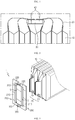
FIG. 1 is a diagram schematically showing a conventional joining configuration of electrode leads and a bus bar. -
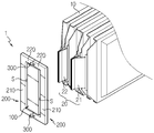
FIGS. 2 and3 are perspective views schematically showing main components of a bus bar assembly according to an embodiment of the present disclosure and a battery cell stack. -
FIG. 4 is a perspective view showing a bus bar support frame according to an embodiment of the present disclosure. -
FIG. 5 is a perspective view showing the bus bar assembly according to an embodiment of the present disclosure before the electrode leads are inserted. -
FIG. 6 is an enlarged view showing a main portion ofFIG. 5 . -
FIG. 7 is a perspective view showing the bus bar assembly according to an embodiment of the present disclosure after the electrode leads are inserted. -
FIG. 8 is an enlarged view showing a main portion ofFIG. 7 . -
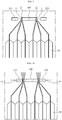
FIGS. 9 and 10 are diagrams showing the configurations before and after the electrode leads and the bus bar assembly are joined according to an embodiment of the present disclosure. - Hereinafter, preferred embodiments of the present disclosure will be described in detail with reference to the accompanying drawings. Prior to the description, it should be understood that the terms used in the specification and the appended claims should not be construed as limited to general and dictionary meanings, but interpreted based on the meanings and concepts corresponding to technical aspects of the present disclosure on the basis of the principle that the inventor is allowed to define terms appropriately for the best explanation.
- Therefore, the description proposed herein is just a preferable example for the purpose of illustrations only, not intended to limit the scope of the disclosure, so it should be understood that other equivalents and modifications could be made thereto without departing from the scope of the disclosure.
- The embodiments disclosed herein are provided for more perfect explanation of the present disclosure, and thus the shape, size and the like of components may be exaggerated, omitted or simplified in the drawings for better understanding. Thus, the size and ratio of components in the drawings do not wholly reflect the actual size and ratio.
-
FIGS. 2 and3 are perspective views schematically showing main components of a bus bar assembly according to an embodiment of the present disclosure and a battery cell stack. - Referring to
FIGS. 2 and3 , thebus bar assembly 1 according to an embodiment of the present disclosure is abus bar assembly 1 for electrically connecting electrode leads 20 of a plurality ofbattery cells 10, and may include afixed bus bar 100, a pair ofmovable bus bars 200, and an adheringmember 300 for allowing relative movements of the pair ofmovable bus bars 200 relative to thefixed bus bar 100. - The
electrode lead 20 of thebattery cell 10 includes apositive electrode lead 21 and anegative electrode lead 22. As will be described in more detail below, according to the present disclosure, thepositive electrode lead 21 and thenegative electrode lead 22 are inserted directly into a fitting space S of thebus bar assembly 1 according to the present disclosure, and end portions of thepositive electrode lead 21 and thenegative electrode lead 22 may be clamped and then welded by thebus bar assembly 1. Thus, it is unnecessary to perform the bending process of theelectrode lead 20 as in the prior art, thereby increasing the automation ratio of the production line. Also, according to the present disclosure, the electrode leads 20 may be welded under mechanical compression. Thus, even when two or more electrode leads 20 are joined in parallel, it is possible to maintain the reliability of electrical connection and the mechanical bonding strength. - Hereinafter, the
bus bar assembly 1 according to the present disclosure will be described in detail. - First, the
fixed bus bar 100 may be made of a rod-shaped material such as copper, silver, and tin-plated copper with electrical conductivity. Thefixed bus bar 100 may allow safe passage of high capacity currents. The positive electrode leads 21 and the negative electrode leads 22 may be adhered and welded to the fixed bus bar and thus be electrically connected thereto. For example, sixbattery cells 10 may be connected in total so that three battery cells are connected in parallel therein. As shown inFIGS. 2 and3 , the positive electrode leads of three battery cells are overlapped and the negative electrode leads of the other three battery cells are overlapped. Then, end portions of the positive electrode leads and the negative electrode leads are inserted into the fitting space S, and then the end portions are adhered and welded to both side surfaces of the fixedbus bar 100 so as to be electrically connected thereto. - The pair of movable bus bars 200 may be made of a metal such as copper, silver, tin plating, or copper with electrical conductivity, similar to the fixed
bus bar 100. - The pair of movable bus bars 200 may be spaced apart from both sides of the fixed
bus bar 100 with the fixedbus bar 100 being interposed therebetween, thereby forming the fitting space S respectively between the pair of movable bus bars 200 and the fixedbus bar 100. That is, the fitting space S is formed at two places at both sides of the fixedbus bar 100. - In addition, the pair of movable bus bars 200 may be provided so as to be movable in the horizontal direction with respect to the fixed
bus bar 100. The pair of movable bus bars 200 may be disposed to be spaced apart from both sides of the fixedbus bar 100 as shown inFIG. 2 and move closer to the fixedbus bar 100 as shown inFIG. 3 . Thus, the width of the fitting space S may be adjusted according to the horizontal movement of the pair of movable bus bars 200, and the electrode leads 20 inserted in this fitting space S may mechanically compressed by the fixedbus bar 100 and the pair of movable bus bars 200. - More specifically, the
movable bus bar 200 of this embodiment may include an adheringportion 210 andgap adjusting portions 220 in an approximately "c" shape. - The adhering
portion 210 may be defined as a portion disposed in parallel with the fixedbus bar 100, and thegap adjusting portions 220 may be defined as portions extending from the both side ends of the adheringportion 210 toward the fixedbus bar 100. - The
movable bus bar 200 is provided in a pair, and the pair of movable bus bars 200 may be disposed symmetrically to each other with the fixedbus bar 100 being interposed therebetween to surround a periphery of the fixedbus bar 100. At this time, the fitting spaces S may be formed between the two adheringportions 210 and both sides of the fixedbus bar 100, so that thegap adjusting portion 220 of onemovable bus bar 200 may be in contact with thegap adjusting portion 220 of the othermovable bus bar 200. Thus, the pair of movable bus bars 200 may be electrically connected to each other. In addition, the width of the fitting space S may be determined according to the length of thegap adjusting portion 220. - Meanwhile, unlike this embodiment, the
movable bus bar 200 is configured to form the fitting space S and press theelectrode lead 20, so themovable bus bar 200 may not necessarily be made of an electrically conductive material. That is, since the positive electrode leads 21 and the negative electrode leads 22 may be sufficiently electrically connected using the fixedbus bar 100, themovable bus bar 200 may be made of an insulating material, different from the fixedbus bar 100. If themovable bus bar 200 is made of an insulating material as an alternative embodiment, a better effect may be obtained in preventing an electrical short circuit inside the battery module. - The adhering
member 300 moves the pair of movable bus bars 200 close to the fixedbus bar 100 so that theelectrode lead 20 is adhered to the fixedbus bar 100. - The adhering
member 300 of this embodiment may be aleaf spring 300 that has both ends respectively coupled to the pair ofmovable bus bars 200 to move the pair of movable bus bars 200 in directions facing each other by means of an elastic restoration force. - For example, referring to
FIGS. 2 and3 , theleaf spring 300 may be coupled to thegap adjusting portion 220 of themovable bus bar 200. At this time, one end of theleaf spring 300 may be coupled to themovable bus bar 200 at the left side, and the other end of theleaf spring 300 may be coupled to themovable bus bar 200 at the right side. More specifically, theleaf spring 300 is provided in a pair, and both ends of the pair ofleaf springs 300 may be coupled to the end portions of thegap adjusting portions 220, which are respectively located at the upper and lower portions of the fixedbus bar 100 and face each other. - As shown in
FIG. 2 , theleaf spring 300 is in a widened state due to an external force. However, if the external force disappears as shown inFIG. 3 , theleaf spring 300 returns to the original state by means of the elastic restoration force. Themovable bus bar 200 may move close to the fixedbus bar 100 by the above operation of theleaf spring 300. -
FIG. 4 is a perspective view showing a bus bar support frame according to an embodiment of the present disclosure,FIGS. 5 and6 are a perspective view and an enlarged view showing the bus bar assembly according to an embodiment of the present disclosure before the electrode leads are inserted, andFIGS. 7 and8 are a perspective view and an enlarged view showing the bus bar assembly according to an embodiment of the present disclosure after the electrode leads are inserted. - Referring to
FIGS. 4 to 8 , thebus bar assembly 1 according to the present disclosure may further include a busbar support frame 400 that gives a place where the fixedbus bar 100 and the pair of movable bus bars 200 may be supported. - The bus
bar support frame 400 may be attached to the front or rear surfaces of a stack of thebattery cells 10. For example, the battery cell stack may be accommodated in a module housing (not shown). The module housing may be provided in a tubular shape having open front and rear surfaces, and the busbar support frame 400 may be coupled to the front and rear surfaces of the module housing and be located at the front and rear surfaces of the battery cell stack. - As shown in
FIG. 4 , the busbar support frame 400 is a plate-shaped structure and has aslit 410 formed between the fixedbus bar 100 and the pair of movable bus bars 200 at a location corresponding to the fitting space S so that theelectrode lead 20 may pass therethrough. Also, theslit 410 is provided to support the bus bars so that the pair of movable bus bars 200 are horizontally movable relative to the fixedbus bar 100. - For this, the bus
bar support frame 400 may further include agap keeping protrusion 420, acantilever beam 430 and acorner bracket 450. - First, the
gap keeping protrusion 420 allows the pair ofmovable bus bars 200 to be spaced apart from both sides of the fixedbus bar 100 in order to secure the fitting space S sufficiently. - As shown in
FIGS. 5 to 8 , thegap keeping protrusion 420 may be provided to be inserted between thegap adjusting portions 220 of the pair of movable bus bars 200 and to be released therefrom. - In other words, the
gap keeping protrusion 420 may be interposed between thegap adjusting portions 220 of the movable bus bars 200 which are pulled apart from each other. If thegap keeping protrusion 420 is interposed between thegap adjusting portions 220, theleaf spring 300 may be kept open. Accordingly, the fitting space S may be sufficiently secured, and a plurality of electrode leads 20 may be disposed to be inserted therein. - In addition, the
gap keeping protrusion 420 may have acantilever beam 430. In this case, if thecantilever beam 430 is lightly pressed, thegap keeping protrusion 420 may be inserted between thegap adjusting portions 220 or released therefrom. - One end of the
cantilever beam 430 is fixed, and the other end thereof is in a free state, and the free end of thecantilever beam 430 may be located at the rear of thegap adjusting portion 220. Thecantilever beam 430 may be formed by cutting a portion of a plate surface of the busbar support frame 400, and thegap keeping protrusion 420 may be provided on the free end of thecantilever beam 430. - In addition, the
cantilever beam 430 may further include apressing protrusion 440 formed to protrude at a location spaced apart from thegap keeping protrusion 420. Thepressing protrusion 440 is provided for pushing thecantilever beam 430 more easily. For example, if thepressing protrusion 440 is pressed by a welding jig (not shown) before theelectrode lead 20 is welded, thecantilever beam 430 is tilted back and thegap keeping protrusion 420 is taken off between thegap adjusting portions 220 of the movable bus bars 200. Also, an elastic restoration force may be applied so that thegap adjusting portions 220 of the movable bus bars 200 are brought into contact with each other. In this case, the fitting space S is narrowed so that the electrode leads 20 interposed therebetween may be tightly adhered to the fixedbus bar 100 and the pair of movable bus bars 200. - Meanwhile, the fixed
bus bar 100 is fixedly attached onto the busbar support frame 400, but themovable bus bar 200 should be movably attached onto the busbar support frame 400. - The
corner bracket 450 of the busbar support frame 400 serves to support themovable bus bar 200 while allowing the movability of themovable bus bar 200. - In this embodiment, four
corner brackets 450 are provided, and the fourcorner brackets 450 are positioned at corner portions of themovable bus bar 200 to restrict themovable bus bar 200 movably. Specifically, thecorner brackets 450 may be configured to surround four corner portions of the pair of movable bus bars 200 in a state where the pair of movable bus bars 200 are spaced farthest from both sides of the fixedbus bar 100, namely where thegap keeping protrusions 420 are inserted therein. In other words, the fourcorner brackets 450 restrain the pair of movable bus bars 200 in upper, lower, left and right directions. Here, for example, a movement allowance space is provided as indicated by D inFIG. 8 , so thatmovable bus bar 200 is movable within the movement allowance space of thecorner bracket 450. - Next, referring to
FIGS. 9 and 10 , the operation of thebus bar assembly 1 according to the present disclosure and the method of joining the electrode leads 20 will be briefly described. This embodiment is an example in which three battery cells are connected in parallel and the positive electrode leads 21 and the negative electrode leads 22 are joined to thebus bar assembly 1. - First, as shown in
FIG. 9 , the fitting space S of thebus bar assembly 1 is secured sufficiently. At this time, the fitting space S may be secured sufficiently by interposing thegap keeping protrusion 420 in the space between thegap adjusting portions 220 of themovable bus bar 200, which is formed by pulling themovable bus bar 200 as described above. - Then, the end portions of the positive electrode leads 21 and the end portions of the negative electrode leads 22 are inserted into the fitting space S, respectively. The fitting space S is provided at two places beside both sides of the fixed
bus bar 100. Only the end portions of the positive electrode leads 21 and the negative electrode leads 22 are inserted into the fitting spaces S in a bundle, respectively. - After that, as shown in
FIG. 10 , the pair of movable bus bars 200 are moved close to the fixedbus bar 100 so that the positive electrode leads 21 and the negative electrode leads 22 are adhered to the fixedbus bar 100. More specifically, thegap keeping protrusion 420 is taken out from the space between the pair of movable bus bars 200 by pressing thecantilever beam 430 using the welding jig (not shown). At this time, the pair of movable bus bars 200 are moved in directions facing each other due to the elastic restoration force of theleaf springs 300, and the end portions of the positive electrode leads 21 and the end portions of the negative electrode leads 22 may integrally compressed between the fixedbus bar 100 themovable bus bar 200. In this state, the positive electrode leads 21 and the negative electrode leads 22 are welded. - According to the structure and operation of the
bus bar assembly 1 of the present disclosure, the process of bending theelectrode lead 20 is not required at all when theelectrode lead 20 is welded, different to the prior art (seeFIG. 1 ). Thus, the manual process for bending the electrode leads 20 may be eliminated to improve the automation ratio of the battery module production line. - In addition, since all of the electrode leads 20 may be welded in a mechanically compressed state, the electrical connectivity and the mechanical bonding strength reliability may be improved regardless of the number of the electrode leads 20 in the parallel connection structure.
- Meanwhile, a battery module according to the present disclosure may include the
bus bar assembly 1 described above. In addition, the battery module includes a battery cell stack, a module housing for accommodating the battery cell stack, and various devices (not shown) for controlling charging and discharging of the battery cells such as a battery management system (BMS), a current sensor and a fuse. The battery module may be used as an energy source for electric vehicles, hybrid electric vehicles or power storage devices. - The present disclosure has been described in detail. However, it should be understood that the detailed description and specific examples, while indicating preferred embodiments of the disclosure, are given by way of illustration only, since various changes and modifications within the scope of the disclosure will become apparent to those skilled in the art from this detailed description.
- Meanwhile, when the terms indicating up, down, left and right directions are used in the specification, it is obvious to those skilled in the art that these merely represent relative locations for convenience in explanation and may vary based on a location of an observer or an object to be observed.
Claims (10)
- A bus bar assembly for electrically connecting a plurality of battery cells having electrode leads, the bus bar assembly comprising:a fixed bus bar provided in the form of a rod-shaped conductor;a pair of movable bus bars disposed to be spaced from both sides of the fixed bus bar in a lateral direction with the fixed bus bar being interposed therebetween to form a fitting space respectively between the pair of movable bus bars and the fixed bus bar so that at least one electrode lead is inserted therein; andan adhering member configured to move the pair of movable bus bars close to the fixed bus bar in a state where the electrode lead is located in the fitting space so that the electrode lead is adhered to the fixed bus bar.
- The bus bar assembly according to claim 1,
wherein each of the pair of movable bus bars includes an adhering portion provided in parallel to the fixed bus bar and gap adjusting portions bent at both side ends of the adhering portion and extending therefrom, and
wherein the pair of movable bus bars are disposed symmetric to each other with the fixed bus bar being interposed therebetween to surround a periphery of the fixed bus bar. - The bus bar assembly according to claim 2,
wherein the adhering member is a leaf spring having both ends respectively coupled to the pair of movable bus bars to move the pair of movable bus bars in directions facing each other by means of an elastic restoration force. - The bus bar assembly according to claim 3,
wherein the leaf spring is provided in a pair, and
wherein both ends of the pair of leaf springs are coupled to end portions of the gap adjusting portions, which face each other at the pair of movable bus bars. - The bus bar assembly according to claim 4, further comprising:
a bus bar support frame serving as a plate-shaped structure and having a slit formed at a location corresponding to the fitting space so that the electrode lead passes therethrough, the bus bar support frame supporting the pair of movable bus bars and the fixed bus bar so that the pair of movable bus bars are movable with respect to the fixed bus bar. - The bus bar assembly according to claim 5,
wherein the bus bar support frame includes a gap keeping protrusion configured to be inserted between the gap adjusting portions of the pair of movable bus bars or released therefrom. - The bus bar assembly according to claim 6,
wherein the bus bar support frame further includes a cantilever beam having a free end located at the rear of the gap adjusting portion, and the gap keeping protrusion is provided at the free end. - The bus bar assembly according to claim 7,
wherein the cantilever beam further includes a pressing protrusion protruding at a location spaced apart from the gap keeping protrusion. - The bus bar assembly according to claim 5,
wherein the bus bar support frame further includes corner brackets configured to surround and support four corner portions of the pair of movable bus bars in a state where the pair of movable bus bars are spaced farthest from both sides of the fixed bus bar in a lateral direction. - A battery module, comprising a bus bar assembly defined in claim 1 or 2.
Priority Applications (1)
| Application Number | Priority Date | Filing Date | Title |
|---|---|---|---|
| PL18866237T PL3637501T3 (en) | 2017-10-10 | 2018-09-03 | COLLECTOR ASSEMBLY FOR CONNECTING THE ELECTRODE OUTLET AND THE BATTERY MODULE CONTAINING IT |
Applications Claiming Priority (2)
| Application Number | Priority Date | Filing Date | Title |
|---|---|---|---|
| KR1020170129091A KR102273184B1 (en) | 2017-10-10 | 2017-10-10 | Bus bar assembly for connecting electrode lead and Battery module including the same |
| PCT/KR2018/010232 WO2019074206A1 (en) | 2017-10-10 | 2018-09-03 | Bus bar assembly for electrode lead bonding and battery module including same |
Publications (3)
| Publication Number | Publication Date |
|---|---|
| EP3637501A1 true EP3637501A1 (en) | 2020-04-15 |
| EP3637501A4 EP3637501A4 (en) | 2020-08-05 |
| EP3637501B1 EP3637501B1 (en) | 2021-03-10 |
Family
ID=66101479
Family Applications (1)
| Application Number | Title | Priority Date | Filing Date |
|---|---|---|---|
| EP18866237.3A Active EP3637501B1 (en) | 2017-10-10 | 2018-09-03 | Bus bar assembly for electrode lead bonding and battery module including same |
Country Status (7)
| Country | Link |
|---|---|
| US (1) | US11302998B2 (en) |
| EP (1) | EP3637501B1 (en) |
| JP (1) | JP7045558B2 (en) |
| KR (1) | KR102273184B1 (en) |
| CN (1) | CN110710027B (en) |
| PL (1) | PL3637501T3 (en) |
| WO (1) | WO2019074206A1 (en) |
Cited By (2)
| Publication number | Priority date | Publication date | Assignee | Title |
|---|---|---|---|---|
| EP3934010A4 (en) * | 2019-06-25 | 2022-04-06 | LG Energy Solution, Ltd. | BATTERY MODULE AND BATTERY PACK COMPRISING THEM |
| EP3916825A4 (en) * | 2019-11-14 | 2023-04-05 | LG Energy Solution, Ltd. | BATTERY MODULE, METHOD OF MAKING A BATTERY MODULE, AND BATTERY PACK COMPRISING A BATTERY MODULE |
Families Citing this family (20)
| Publication number | Priority date | Publication date | Assignee | Title |
|---|---|---|---|---|
| WO2020194783A1 (en) * | 2019-03-27 | 2020-10-01 | 三洋電機株式会社 | Power supply device, electric vehicle comprising power supply device, and power storage device |
| KR102541537B1 (en) * | 2019-06-25 | 2023-06-08 | 주식회사 엘지에너지솔루션 | Battery module and battery pack including the same |
| KR102791126B1 (en) | 2019-09-03 | 2025-04-02 | 주식회사 엘지에너지솔루션 | Length-adjustable inter-busbar |
| KR102799955B1 (en) * | 2019-10-08 | 2025-04-25 | 주식회사 엘지에너지솔루션 | Connecting Member Connected to Electrode Lead by Physical Coupling and Battery Cell Stack Comprising the Same |
| KR102769905B1 (en) | 2019-10-24 | 2025-02-17 | 주식회사 엘지에너지솔루션 | Battery module, battery pack and vehicle comprising the battery module |
| KR102811566B1 (en) | 2019-11-15 | 2025-05-22 | 주식회사 엘지에너지솔루션 | High voltage battery module comprising external bridge busbar |
| KR102786523B1 (en) | 2019-12-06 | 2025-03-24 | 주식회사 엘지에너지솔루션 | Battery module, battery pack and vehicle comprising the battery module |
| KR102786405B1 (en) * | 2019-12-06 | 2025-03-24 | 주식회사 엘지에너지솔루션 | Battery module, battery pack and vehicle comprising the battery module |
| KR102926741B1 (en) * | 2020-03-02 | 2026-02-11 | 주식회사 엘지에너지솔루션 | Battery module having a structure in which a terminal part of pcb and a bus bar are directly connected |
| CN115769432A (en) * | 2021-03-01 | 2023-03-07 | 日本汽车能源株式会社 | Battery pack and battery pack manufacturing method |
| EP4203171B1 (en) * | 2021-05-03 | 2025-10-15 | LG Energy Solution, Ltd. | Battery module and battery pack including same |
| EP4399763A4 (en) | 2021-09-10 | 2025-07-09 | Milwaukee Electric Tool Corp | BATTERY PACK |
| KR102359235B1 (en) | 2021-09-16 | 2022-02-08 | 주식회사 신룡 | Lead automatic forming apparatus for assembling bus-bar and lead automatic forming method using the same |
| KR102434262B1 (en) | 2021-09-17 | 2022-08-22 | 주식회사 신룡 | Lead automatic forming apparatus for assembling bus-bar and lead automatic forming method using the same |
| WO2023228030A1 (en) * | 2022-05-25 | 2023-11-30 | Molex, Llc | Busbar assembly for joining battery cells |
| CN115954620A (en) * | 2022-08-25 | 2023-04-11 | 孚能科技(赣州)股份有限公司 | Cell connectors and battery modules |
| US20240079747A1 (en) * | 2022-09-02 | 2024-03-07 | Ford Global Technologies, Llc | Traction battery pack tab terminal securing system and securing method |
| KR20240079058A (en) * | 2022-11-28 | 2024-06-04 | 주식회사 엘지에너지솔루션 | Battery sub module |
| WO2026018430A1 (en) * | 2024-07-19 | 2026-01-22 | 日産自動車株式会社 | Battery module |
| WO2026043148A1 (en) * | 2024-08-19 | 2026-02-26 | 주식회사 엘지에너지솔루션 | Method for manufacturing secondary battery, secondary battery, and battery module, battery pack and transportation means comprising same |
Family Cites Families (23)
| Publication number | Priority date | Publication date | Assignee | Title |
|---|---|---|---|---|
| JPH1125951A (en) | 1997-07-07 | 1999-01-29 | Sanyo Electric Co Ltd | Battery |
| JP4832018B2 (en) | 2005-07-22 | 2011-12-07 | トヨタ自動車株式会社 | Assembled battery |
| JP2007087907A (en) | 2005-09-26 | 2007-04-05 | Fuji Heavy Ind Ltd | Case structure of battery cell |
| JP5225246B2 (en) | 2009-10-20 | 2013-07-03 | 日本航空電子工業株式会社 | Battery connection device |
| JP2013206844A (en) * | 2012-03-29 | 2013-10-07 | Captex Co Ltd | Electrode connection structure in laminate cell battery |
| JP2014002905A (en) | 2012-06-18 | 2014-01-09 | Captex Co Ltd | Electrode connection structure |
| KR102024002B1 (en) * | 2012-07-05 | 2019-09-23 | 에스케이이노베이션 주식회사 | Battery pack |
| JP2014053104A (en) | 2012-09-05 | 2014-03-20 | Captex Co Ltd | Electrode connection structure |
| KR101732285B1 (en) * | 2012-11-09 | 2017-05-02 | 닛산 지도우샤 가부시키가이샤 | Assembled battery and method for manufacturing assembled battery |
| KR102007459B1 (en) | 2012-12-27 | 2019-08-05 | 에스케이이노베이션 주식회사 | Battery cell tab connecting apparatus and battery modul by using the same |
| KR20140093424A (en) * | 2013-01-18 | 2014-07-28 | 타이코에이엠피(유) | Battery module |
| JP6062266B2 (en) | 2013-01-30 | 2017-01-18 | 矢崎総業株式会社 | Bus bar module and power supply |
| KR20140140744A (en) | 2013-05-30 | 2014-12-10 | 삼성에스디아이 주식회사 | Battery module |
| JP6011876B2 (en) * | 2013-09-13 | 2016-10-19 | 株式会社オートネットワーク技術研究所 | Power storage module |
| JP5929937B2 (en) * | 2014-01-30 | 2016-06-08 | トヨタ自動車株式会社 | Battery pack and battery connection switching method |
| KR101565115B1 (en) | 2014-03-31 | 2015-11-02 | (주)탑전지 | Battery Pack and method for manufacturing the same |
| KR102214538B1 (en) | 2014-05-30 | 2021-02-09 | 에스케이이노베이션 주식회사 | Unit battery module and Battery module having the same |
| KR101831816B1 (en) * | 2015-02-06 | 2018-02-23 | 주식회사 엘지화학 | Cell Module Improved Weldability |
| KR102381777B1 (en) | 2015-02-25 | 2022-04-01 | 삼성에스디아이 주식회사 | Battery pack |
| KR102424640B1 (en) | 2015-12-29 | 2022-07-25 | 에이치그린파워 주식회사 | Battery module and Method for assembling the same |
| KR102284340B1 (en) * | 2016-01-19 | 2021-08-03 | 에스케이이노베이션 주식회사 | Battery pack |
| KR101806513B1 (en) | 2017-11-17 | 2018-01-10 | 엘지디스플레이 주식회사 | Electrophoresis display device |
| KR102258819B1 (en) * | 2017-11-24 | 2021-05-31 | 주식회사 엘지에너지솔루션 | Battery Module with improved electrical connection safety |
-
2017
- 2017-10-10 KR KR1020170129091A patent/KR102273184B1/en active Active
-
2018
- 2018-09-03 EP EP18866237.3A patent/EP3637501B1/en active Active
- 2018-09-03 JP JP2019564812A patent/JP7045558B2/en active Active
- 2018-09-03 CN CN201880036437.7A patent/CN110710027B/en active Active
- 2018-09-03 WO PCT/KR2018/010232 patent/WO2019074206A1/en not_active Ceased
- 2018-09-03 US US16/617,115 patent/US11302998B2/en active Active
- 2018-09-03 PL PL18866237T patent/PL3637501T3/en unknown
Cited By (3)
| Publication number | Priority date | Publication date | Assignee | Title |
|---|---|---|---|---|
| EP3934010A4 (en) * | 2019-06-25 | 2022-04-06 | LG Energy Solution, Ltd. | BATTERY MODULE AND BATTERY PACK COMPRISING THEM |
| US12255355B2 (en) | 2019-06-25 | 2025-03-18 | Lg Energy Solution, Ltd. | Battery module including bus bar frame with fixing portions covering bus bar and battery pack including the same |
| EP3916825A4 (en) * | 2019-11-14 | 2023-04-05 | LG Energy Solution, Ltd. | BATTERY MODULE, METHOD OF MAKING A BATTERY MODULE, AND BATTERY PACK COMPRISING A BATTERY MODULE |
Also Published As
| Publication number | Publication date |
|---|---|
| CN110710027A (en) | 2020-01-17 |
| WO2019074206A1 (en) | 2019-04-18 |
| CN110710027B (en) | 2022-03-15 |
| US11302998B2 (en) | 2022-04-12 |
| EP3637501A4 (en) | 2020-08-05 |
| JP2020521297A (en) | 2020-07-16 |
| US20200350547A1 (en) | 2020-11-05 |
| KR102273184B1 (en) | 2021-07-05 |
| KR20190040402A (en) | 2019-04-18 |
| PL3637501T3 (en) | 2021-07-12 |
| JP7045558B2 (en) | 2022-04-01 |
| EP3637501B1 (en) | 2021-03-10 |
Similar Documents
| Publication | Publication Date | Title |
|---|---|---|
| EP3637501B1 (en) | Bus bar assembly for electrode lead bonding and battery module including same | |
| EP3637502B1 (en) | Bus bar assembly for electrode lead bonding and battery module including same | |
| EP3282515B1 (en) | Battery module, battery pack comprising battery module, and vehicle comprising battery pack | |
| CN106133948B (en) | Battery module and battery pack including the same | |
| JP6793841B2 (en) | Battery module, battery pack including it and automobile | |
| CN210120177U (en) | Battery module, battery pack including the same, and vehicle including the battery pack | |
| JP7041799B2 (en) | Battery module and battery pack containing it | |
| EP3154108B1 (en) | Battery module and battery pack including same | |
| EP3783693B1 (en) | Battery module, battery pack comprising same battery module, and vehicle comprising same battery pack | |
| EP3731302A1 (en) | Battery module, battery pack comprising same battery module, and vehicle comprising same battery pack | |
| JP7447318B2 (en) | Battery modules, battery packs and automobiles | |
| EP4084206A1 (en) | Battery module, and battery pack and vehicle comprising battery module | |
| EP3951804B1 (en) | Ffc cable assembly | |
| KR102378571B1 (en) | Battery module, battery pack and vehicle comprising the same | |
| EP4087012B1 (en) | Battery module, and battery pack and vehicle which comprise same | |
| EP4391202A1 (en) | Battery module |
Legal Events
| Date | Code | Title | Description |
|---|---|---|---|
| STAA | Information on the status of an ep patent application or granted ep patent |
Free format text: STATUS: THE INTERNATIONAL PUBLICATION HAS BEEN MADE |
|
| PUAI | Public reference made under article 153(3) epc to a published international application that has entered the european phase |
Free format text: ORIGINAL CODE: 0009012 |
|
| STAA | Information on the status of an ep patent application or granted ep patent |
Free format text: STATUS: REQUEST FOR EXAMINATION WAS MADE |
|
| 17P | Request for examination filed |
Effective date: 20200108 |
|
| AK | Designated contracting states |
Kind code of ref document: A1 Designated state(s): AL AT BE BG CH CY CZ DE DK EE ES FI FR GB GR HR HU IE IS IT LI LT LU LV MC MK MT NL NO PL PT RO RS SE SI SK SM TR |
|
| AX | Request for extension of the european patent |
Extension state: BA ME |
|
| A4 | Supplementary search report drawn up and despatched |
Effective date: 20200702 |
|
| RIC1 | Information provided on ipc code assigned before grant |
Ipc: H01M 2/26 20060101ALI20200626BHEP Ipc: H01M 2/20 20060101AFI20200626BHEP Ipc: H01R 4/48 20060101ALI20200626BHEP |
|
| GRAP | Despatch of communication of intention to grant a patent |
Free format text: ORIGINAL CODE: EPIDOSNIGR1 |
|
| STAA | Information on the status of an ep patent application or granted ep patent |
Free format text: STATUS: GRANT OF PATENT IS INTENDED |
|
| RIC1 | Information provided on ipc code assigned before grant |
Ipc: H01M 2/26 20060101ALI20201124BHEP Ipc: H01R 4/02 20060101ALI20201124BHEP Ipc: H01M 2/20 20060101AFI20201124BHEP Ipc: H01R 4/48 20060101ALI20201124BHEP |
|
| DAV | Request for validation of the european patent (deleted) | ||
| DAX | Request for extension of the european patent (deleted) | ||
| INTG | Intention to grant announced |
Effective date: 20201218 |
|
| GRAS | Grant fee paid |
Free format text: ORIGINAL CODE: EPIDOSNIGR3 |
|
| GRAA | (expected) grant |
Free format text: ORIGINAL CODE: 0009210 |
|
| STAA | Information on the status of an ep patent application or granted ep patent |
Free format text: STATUS: THE PATENT HAS BEEN GRANTED |
|
| AK | Designated contracting states |
Kind code of ref document: B1 Designated state(s): AL AT BE BG CH CY CZ DE DK EE ES FI FR GB GR HR HU IE IS IT LI LT LU LV MC MK MT NL NO PL PT RO RS SE SI SK SM TR |
|
| REG | Reference to a national code |
Ref country code: GB Ref legal event code: FG4D |
|
| REG | Reference to a national code |
Ref country code: AT Ref legal event code: REF Ref document number: 1370802 Country of ref document: AT Kind code of ref document: T Effective date: 20210315 Ref country code: CH Ref legal event code: EP |
|
| REG | Reference to a national code |
Ref country code: DE Ref legal event code: R096 Ref document number: 602018013873 Country of ref document: DE |
|
| REG | Reference to a national code |
Ref country code: IE Ref legal event code: FG4D |
|
| REG | Reference to a national code |
Ref country code: SE Ref legal event code: TRGR |
|
| REG | Reference to a national code |
Ref country code: LT Ref legal event code: MG9D |
|
| PG25 | Lapsed in a contracting state [announced via postgrant information from national office to epo] |
Ref country code: BG Free format text: LAPSE BECAUSE OF FAILURE TO SUBMIT A TRANSLATION OF THE DESCRIPTION OR TO PAY THE FEE WITHIN THE PRESCRIBED TIME-LIMIT Effective date: 20210610 Ref country code: FI Free format text: LAPSE BECAUSE OF FAILURE TO SUBMIT A TRANSLATION OF THE DESCRIPTION OR TO PAY THE FEE WITHIN THE PRESCRIBED TIME-LIMIT Effective date: 20210310 Ref country code: GR Free format text: LAPSE BECAUSE OF FAILURE TO SUBMIT A TRANSLATION OF THE DESCRIPTION OR TO PAY THE FEE WITHIN THE PRESCRIBED TIME-LIMIT Effective date: 20210611 Ref country code: HR Free format text: LAPSE BECAUSE OF FAILURE TO SUBMIT A TRANSLATION OF THE DESCRIPTION OR TO PAY THE FEE WITHIN THE PRESCRIBED TIME-LIMIT Effective date: 20210310 Ref country code: NO Free format text: LAPSE BECAUSE OF FAILURE TO SUBMIT A TRANSLATION OF THE DESCRIPTION OR TO PAY THE FEE WITHIN THE PRESCRIBED TIME-LIMIT Effective date: 20210610 Ref country code: LT Free format text: LAPSE BECAUSE OF FAILURE TO SUBMIT A TRANSLATION OF THE DESCRIPTION OR TO PAY THE FEE WITHIN THE PRESCRIBED TIME-LIMIT Effective date: 20210310 |
|
| REG | Reference to a national code |
Ref country code: AT Ref legal event code: MK05 Ref document number: 1370802 Country of ref document: AT Kind code of ref document: T Effective date: 20210310 |
|
| REG | Reference to a national code |
Ref country code: NL Ref legal event code: MP Effective date: 20210310 |
|
| PG25 | Lapsed in a contracting state [announced via postgrant information from national office to epo] |
Ref country code: RS Free format text: LAPSE BECAUSE OF FAILURE TO SUBMIT A TRANSLATION OF THE DESCRIPTION OR TO PAY THE FEE WITHIN THE PRESCRIBED TIME-LIMIT Effective date: 20210310 Ref country code: LV Free format text: LAPSE BECAUSE OF FAILURE TO SUBMIT A TRANSLATION OF THE DESCRIPTION OR TO PAY THE FEE WITHIN THE PRESCRIBED TIME-LIMIT Effective date: 20210310 |
|
| PG25 | Lapsed in a contracting state [announced via postgrant information from national office to epo] |
Ref country code: NL Free format text: LAPSE BECAUSE OF FAILURE TO SUBMIT A TRANSLATION OF THE DESCRIPTION OR TO PAY THE FEE WITHIN THE PRESCRIBED TIME-LIMIT Effective date: 20210310 |
|
| PG25 | Lapsed in a contracting state [announced via postgrant information from national office to epo] |
Ref country code: AT Free format text: LAPSE BECAUSE OF FAILURE TO SUBMIT A TRANSLATION OF THE DESCRIPTION OR TO PAY THE FEE WITHIN THE PRESCRIBED TIME-LIMIT Effective date: 20210310 Ref country code: SM Free format text: LAPSE BECAUSE OF FAILURE TO SUBMIT A TRANSLATION OF THE DESCRIPTION OR TO PAY THE FEE WITHIN THE PRESCRIBED TIME-LIMIT Effective date: 20210310 Ref country code: CZ Free format text: LAPSE BECAUSE OF FAILURE TO SUBMIT A TRANSLATION OF THE DESCRIPTION OR TO PAY THE FEE WITHIN THE PRESCRIBED TIME-LIMIT Effective date: 20210310 Ref country code: EE Free format text: LAPSE BECAUSE OF FAILURE TO SUBMIT A TRANSLATION OF THE DESCRIPTION OR TO PAY THE FEE WITHIN THE PRESCRIBED TIME-LIMIT Effective date: 20210310 |
|
| PG25 | Lapsed in a contracting state [announced via postgrant information from national office to epo] |
Ref country code: IS Free format text: LAPSE BECAUSE OF FAILURE TO SUBMIT A TRANSLATION OF THE DESCRIPTION OR TO PAY THE FEE WITHIN THE PRESCRIBED TIME-LIMIT Effective date: 20210710 Ref country code: PT Free format text: LAPSE BECAUSE OF FAILURE TO SUBMIT A TRANSLATION OF THE DESCRIPTION OR TO PAY THE FEE WITHIN THE PRESCRIBED TIME-LIMIT Effective date: 20210712 Ref country code: RO Free format text: LAPSE BECAUSE OF FAILURE TO SUBMIT A TRANSLATION OF THE DESCRIPTION OR TO PAY THE FEE WITHIN THE PRESCRIBED TIME-LIMIT Effective date: 20210310 Ref country code: SK Free format text: LAPSE BECAUSE OF FAILURE TO SUBMIT A TRANSLATION OF THE DESCRIPTION OR TO PAY THE FEE WITHIN THE PRESCRIBED TIME-LIMIT Effective date: 20210310 |
|
| REG | Reference to a national code |
Ref country code: DE Ref legal event code: R097 Ref document number: 602018013873 Country of ref document: DE |
|
| PLBE | No opposition filed within time limit |
Free format text: ORIGINAL CODE: 0009261 |
|
| STAA | Information on the status of an ep patent application or granted ep patent |
Free format text: STATUS: NO OPPOSITION FILED WITHIN TIME LIMIT |
|
| RAP2 | Party data changed (patent owner data changed or rights of a patent transferred) |
Owner name: LG ENERGY SOLUTION LTD. |
|
| PG25 | Lapsed in a contracting state [announced via postgrant information from national office to epo] |
Ref country code: DK Free format text: LAPSE BECAUSE OF FAILURE TO SUBMIT A TRANSLATION OF THE DESCRIPTION OR TO PAY THE FEE WITHIN THE PRESCRIBED TIME-LIMIT Effective date: 20210310 Ref country code: AL Free format text: LAPSE BECAUSE OF FAILURE TO SUBMIT A TRANSLATION OF THE DESCRIPTION OR TO PAY THE FEE WITHIN THE PRESCRIBED TIME-LIMIT Effective date: 20210310 Ref country code: ES Free format text: LAPSE BECAUSE OF FAILURE TO SUBMIT A TRANSLATION OF THE DESCRIPTION OR TO PAY THE FEE WITHIN THE PRESCRIBED TIME-LIMIT Effective date: 20210310 |
|
| 26N | No opposition filed |
Effective date: 20211213 |
|
| PG25 | Lapsed in a contracting state [announced via postgrant information from national office to epo] |
Ref country code: SI Free format text: LAPSE BECAUSE OF FAILURE TO SUBMIT A TRANSLATION OF THE DESCRIPTION OR TO PAY THE FEE WITHIN THE PRESCRIBED TIME-LIMIT Effective date: 20210310 |
|
| PG25 | Lapsed in a contracting state [announced via postgrant information from national office to epo] |
Ref country code: IT Free format text: LAPSE BECAUSE OF FAILURE TO SUBMIT A TRANSLATION OF THE DESCRIPTION OR TO PAY THE FEE WITHIN THE PRESCRIBED TIME-LIMIT Effective date: 20210310 |
|
| REG | Reference to a national code |
Ref country code: CH Ref legal event code: PL |
|
| REG | Reference to a national code |
Ref country code: BE Ref legal event code: MM Effective date: 20210930 |
|
| PG25 | Lapsed in a contracting state [announced via postgrant information from national office to epo] |
Ref country code: IS Free format text: LAPSE BECAUSE OF FAILURE TO SUBMIT A TRANSLATION OF THE DESCRIPTION OR TO PAY THE FEE WITHIN THE PRESCRIBED TIME-LIMIT Effective date: 20210710 Ref country code: MC Free format text: LAPSE BECAUSE OF FAILURE TO SUBMIT A TRANSLATION OF THE DESCRIPTION OR TO PAY THE FEE WITHIN THE PRESCRIBED TIME-LIMIT Effective date: 20210310 |
|
| PG25 | Lapsed in a contracting state [announced via postgrant information from national office to epo] |
Ref country code: LU Free format text: LAPSE BECAUSE OF NON-PAYMENT OF DUE FEES Effective date: 20210903 Ref country code: IE Free format text: LAPSE BECAUSE OF NON-PAYMENT OF DUE FEES Effective date: 20210903 Ref country code: BE Free format text: LAPSE BECAUSE OF NON-PAYMENT OF DUE FEES Effective date: 20210930 |
|
| PG25 | Lapsed in a contracting state [announced via postgrant information from national office to epo] |
Ref country code: LI Free format text: LAPSE BECAUSE OF NON-PAYMENT OF DUE FEES Effective date: 20210930 Ref country code: CH Free format text: LAPSE BECAUSE OF NON-PAYMENT OF DUE FEES Effective date: 20210930 |
|
| REG | Reference to a national code |
Ref country code: DE Ref legal event code: R081 Ref document number: 602018013873 Country of ref document: DE Owner name: LG ENERGY SOLUTION, LTD., KR Free format text: FORMER OWNER: LG CHEM, LTD., SEOUL, KR |
|
| P01 | Opt-out of the competence of the unified patent court (upc) registered |
Effective date: 20230408 |
|
| PG25 | Lapsed in a contracting state [announced via postgrant information from national office to epo] |
Ref country code: CY Free format text: LAPSE BECAUSE OF FAILURE TO SUBMIT A TRANSLATION OF THE DESCRIPTION OR TO PAY THE FEE WITHIN THE PRESCRIBED TIME-LIMIT Effective date: 20210310 |
|
| PG25 | Lapsed in a contracting state [announced via postgrant information from national office to epo] |
Ref country code: HU Free format text: LAPSE BECAUSE OF FAILURE TO SUBMIT A TRANSLATION OF THE DESCRIPTION OR TO PAY THE FEE WITHIN THE PRESCRIBED TIME-LIMIT; INVALID AB INITIO Effective date: 20180903 |
|
| REG | Reference to a national code |
Ref country code: GB Ref legal event code: 732E Free format text: REGISTERED BETWEEN 20230901 AND 20230906 |
|
| PG25 | Lapsed in a contracting state [announced via postgrant information from national office to epo] |
Ref country code: MK Free format text: LAPSE BECAUSE OF FAILURE TO SUBMIT A TRANSLATION OF THE DESCRIPTION OR TO PAY THE FEE WITHIN THE PRESCRIBED TIME-LIMIT Effective date: 20210310 |
|
| PG25 | Lapsed in a contracting state [announced via postgrant information from national office to epo] |
Ref country code: TR Free format text: LAPSE BECAUSE OF FAILURE TO SUBMIT A TRANSLATION OF THE DESCRIPTION OR TO PAY THE FEE WITHIN THE PRESCRIBED TIME-LIMIT Effective date: 20210310 |
|
| PG25 | Lapsed in a contracting state [announced via postgrant information from national office to epo] |
Ref country code: MT Free format text: LAPSE BECAUSE OF FAILURE TO SUBMIT A TRANSLATION OF THE DESCRIPTION OR TO PAY THE FEE WITHIN THE PRESCRIBED TIME-LIMIT Effective date: 20210310 |
|
| PGFP | Annual fee paid to national office [announced via postgrant information from national office to epo] |
Ref country code: DE Payment date: 20250820 Year of fee payment: 8 |
|
| PGFP | Annual fee paid to national office [announced via postgrant information from national office to epo] |
Ref country code: PL Payment date: 20250822 Year of fee payment: 8 |
|
| PGFP | Annual fee paid to national office [announced via postgrant information from national office to epo] |
Ref country code: GB Payment date: 20250820 Year of fee payment: 8 |
|
| PGFP | Annual fee paid to national office [announced via postgrant information from national office to epo] |
Ref country code: FR Payment date: 20250821 Year of fee payment: 8 |
|
| PGFP | Annual fee paid to national office [announced via postgrant information from national office to epo] |
Ref country code: SE Payment date: 20250821 Year of fee payment: 8 |