EP3637206B1 - Electric lifting platform capable of retracting upon encountering resistance - Google Patents
Electric lifting platform capable of retracting upon encountering resistance Download PDFInfo
- Publication number
- EP3637206B1 EP3637206B1 EP18813141.1A EP18813141A EP3637206B1 EP 3637206 B1 EP3637206 B1 EP 3637206B1 EP 18813141 A EP18813141 A EP 18813141A EP 3637206 B1 EP3637206 B1 EP 3637206B1
- Authority
- EP
- European Patent Office
- Prior art keywords
- axis
- sensor module
- controller
- lift platform
- electric lift
- Prior art date
- Legal status (The legal status is an assumption and is not a legal conclusion. Google has not performed a legal analysis and makes no representation as to the accuracy of the status listed.)
- Active
Links
Images

Classifications
-
- G—PHYSICS
- G05—CONTROLLING; REGULATING
- G05B—CONTROL OR REGULATING SYSTEMS IN GENERAL; FUNCTIONAL ELEMENTS OF SUCH SYSTEMS; MONITORING OR TESTING ARRANGEMENTS FOR SUCH SYSTEMS OR ELEMENTS
- G05B19/00—Program-control systems
- G05B19/02—Program-control systems electric
- G05B19/04—Program control other than numerical control, i.e. in sequence controllers or logic controllers
- G05B19/042—Program control other than numerical control, i.e. in sequence controllers or logic controllers using digital processors
- G05B19/0426—Programming the control sequence
-
- A—HUMAN NECESSITIES
- A47—FURNITURE; DOMESTIC ARTICLES OR APPLIANCES; COFFEE MILLS; SPICE MILLS; SUCTION CLEANERS IN GENERAL
- A47B—TABLES; DESKS; OFFICE FURNITURE; CABINETS; DRAWERS; GENERAL DETAILS OF FURNITURE
- A47B9/00—Tables with tops of variable height
- A47B9/16—Tables with tops of variable height with means for, or adapted for, inclining the legs of the table for varying the height of the top, e.g. with adjustable cross legs
-
- A—HUMAN NECESSITIES
- A47—FURNITURE; DOMESTIC ARTICLES OR APPLIANCES; COFFEE MILLS; SPICE MILLS; SUCTION CLEANERS IN GENERAL
- A47B—TABLES; DESKS; OFFICE FURNITURE; CABINETS; DRAWERS; GENERAL DETAILS OF FURNITURE
- A47B9/00—Tables with tops of variable height
- A47B9/20—Telescopic guides
-
- A—HUMAN NECESSITIES
- A61—MEDICAL OR VETERINARY SCIENCE; HYGIENE
- A61G—TRANSPORT, PERSONAL CONVEYANCES OR ACCOMMODATION SPECIALLY ADAPTED FOR PATIENTS OR DISABLED PERSONS; OPERATING TABLES OR CHAIRS; CHAIRS FOR DENTISTRY; FUNERAL DEVICES
- A61G13/00—Operating tables; Auxiliary appliances therefor
- A61G13/02—Adjustable operating tables; Controls therefor
- A61G13/04—Adjustable operating tables; Controls therefor tiltable around transverse or longitudinal axis
-
- A—HUMAN NECESSITIES
- A61—MEDICAL OR VETERINARY SCIENCE; HYGIENE
- A61G—TRANSPORT, PERSONAL CONVEYANCES OR ACCOMMODATION SPECIALLY ADAPTED FOR PATIENTS OR DISABLED PERSONS; OPERATING TABLES OR CHAIRS; CHAIRS FOR DENTISTRY; FUNERAL DEVICES
- A61G7/00—Beds specially adapted for nursing; Devices for lifting patients or disabled persons
- A61G7/002—Beds specially adapted for nursing; Devices for lifting patients or disabled persons having adjustable mattress frame
- A61G7/018—Control or drive mechanisms
-
- A—HUMAN NECESSITIES
- A47—FURNITURE; DOMESTIC ARTICLES OR APPLIANCES; COFFEE MILLS; SPICE MILLS; SUCTION CLEANERS IN GENERAL
- A47B—TABLES; DESKS; OFFICE FURNITURE; CABINETS; DRAWERS; GENERAL DETAILS OF FURNITURE
- A47B2200/00—General construction of tables or desks
- A47B2200/0035—Tables or desks with features relating to adjustability or folding
- A47B2200/005—Leg adjustment
- A47B2200/0056—Leg adjustment with a motor, e.g. an electric motor
-
- G—PHYSICS
- G05—CONTROLLING; REGULATING
- G05B—CONTROL OR REGULATING SYSTEMS IN GENERAL; FUNCTIONAL ELEMENTS OF SUCH SYSTEMS; MONITORING OR TESTING ARRANGEMENTS FOR SUCH SYSTEMS OR ELEMENTS
- G05B2219/00—Program-control systems
- G05B2219/20—Pc systems
- G05B2219/26—Pc applications
- G05B2219/2608—Hospital bed
Definitions
- the present disclosure relates to an electric lift platform, and more particularly relates to an electric lift platform retractable upon hitting an obstruction.
- Electric lift platforms are generally applied in houses, offices and medical facilities, such as height-adjustable writing desks, kitchen islands, tatamis, office desks, and hospital beds, etc. If the platform or its frame hits an obstacle during lift adjustment, a surrounding structure or the structure of the platform proper could be possibly damaged; it also poses a risk of impacting or squeezing the human body. With the ever-higher demand on product safety, impact detection and obstruction-hitting handling of a lift platform become more and more important.
- An objective of the present disclosure is to provide an electric lift platform retractable upon hitting an obstruction, which is more sensitive and safer.
- the present disclosure discloses an electric lift platform retractable upon hitting an obstruction.
- the electric lift platform is an electric liftin desk, such that the platform refers to the desktop of the electric lift desk.
- the electric lift desk comprises a lifting column 1, a desktop 2, a controller 4, a manipulator 5, and a multi-axis sensor module 6 for acquiring platform obstruction-hitting data, wherein the multi-axis sensor module 6 acquires variations of motion statuses of the desktop 2 along different axes, satisfying detection of motion statuses of the desktop 2 caused by different obstacles at different positions; besides, the detection is not affected by assembly of the lift platform and is less demanding on the installation position.
- the controller 4 comprises a power supply module 41, a main control unit MCU 42, and a motor driver circuit 43, wherein the output end of the MCU 42 is connected to the motor driver circuit 43, and the multi-axis sensor module 6 is connected to the input end of the MCU 42, such that the MCU 42, after having processed the obstruction-hitting data, transmits a control signal to the motor driver circuit 43, and the latter controls the lifting column 1 to execute a corresponding retract action; in this way, safety of the electric lift platform is significantly improved.
- the MCU adopts a Freescale HCS08 family microcontroller, which is reliable in motor driver applications; in this way, reliability of the electric lift platform is improved.
- the obstruction-hitting data include accelerations along the X-axis, Y-axis, and Z-axis and/or angular velocities along the three axes;
- the plane where the desktop 2 is located is a plane formed between any two of the X-axis, Y-axis, and Z-axis; and the obstruction-hitting data as acquired include the accelerations along the three axes and/or the angular velocities along the three axes;.
- the three-axis data acquisition offers a higher detection sensitivity. Besides, with the three-axis data, detection can be still implemented even the desktop 2 does not tilt.
- the controller 4 actuates the lifting column to execute a retract action.
- the multi-axis sensor module can directly implement sensing without sensing the tilt angle of the platform. Therefore, the actuation manner in this embodiment is not restricted by whether the desktop 2 tilts, and even the desktop 2 does not tilt, it can be still sensed that the desktop 2 hits an obstacle. In this way, more platform accidental situations can be sensed with a higher sense speed, a higher sensitivity, and a higher accuracy; further, due to not relying on a tilt angle of the desktop 2, the judgement can be performed before tilting of the desktop.
- the three-axis accelerometer 611 and the three-axis gyroscope 612 realize impact detection; in this way, the detection sensibility is improved and safety of the electric lift platform is enhanced.
- obstruction-hitting data may be acquired independently by the three-axis accelerometer 611 or the three-axis gyroscope 612 to judge whether the platform hits an obstacle.
- repeated experiments show that joint detection by the three-axis accelerometer 611 and the three-axis gyroscope 612 yields higher sensitivity and accuracy.
- the central processing unit 62 adopts a highly cost-effective STM32F051K86-model microcomputer.
- the central processing unit 62 is electrically connected to the MPU6050 module 61.
- the central processing unit 62 or the MCU 42 further comprises a filter module 621 for filtering the three-axis acceleration data and the three-axis angular velocity data. Through data filtering, a normal lift may be distinguished from an impact, thereby avoiding misjudging a normal lift as an impact, which enhances efficiency of impact reaction.
- the central processing unit 62 is connected to the input end of the MCU42 to transmit the filtered data to the latter.
- the MCU 42 after having processed the obstruction-hitting data, transmits a control signal to a motor driver circuit 43 which then controls the lifting column 1 to execute a corresponding retract action; in this way, the electric lift platform can efficiently and quickly react to the impact to execute a retract action, improving safety of the electric lift platform.
- the multi-axis sensor module 6 may further comprise a three-axis magnetometer 63, wherein the three-axis magnetometer 63 is electrically connected to the MPU6050 module 61, such that the direction data acquired by the three-axis magnetometer 63, together with the three-axis acceleration data and the three-axis angular data in the MUP6050 module 61, are outputted to the central processing unit 62.
- the three-axis magnetometer 63 adopts a high-precision HMC5883L-model three-axis magnetometer.
- this embodiment adopts a six-axis sensor, there are correspondingly six preset values, i.e., the acceleration of X-axis, the acceleration of Y-axis, and the acceleration of Z-axis, the angular velocity of X-axis, the angular velocity of Y-axis, and the angular velocity of Z-axis, all have their respective preset values.
- the motor driver circuit works.
- preset values and preset margins may be customized by the user dependent on different actual use environments. Additionally, in other embodiments, the preset values may also be written into the multi-axis sensor.
- the controller 4 further comprises a feedback circuit 44 for monitoring stability of the internal circuit of the controller 4.
- the feedback circuit 44 constantly monitors the voltage and current statuses inside the entire controller 4, and monitors information such as the motor rotating speed and operating temperature, etc., so as to adopt a corresponding protection measure to handle exceptions, e.g., Stop Error alarm, power outage, etc., which enhances safety of the controller and makes the electric lift platform more reliable.
- the multi-axis sensor module 6 may be fixed inside the controller 4 via a pin header, which improves detection sensitivity and enhances safety of the electric lift platform.
- the controller 4 is provided on the desktop 2, such that it does not affect fitting with other components of the electric lift platform; instead, it improves impact detection reliability of the lift platform and greatly enhances safety of the electric lift platform.
- the electric lift platform may also be a height adjustable kitchen island and the platform refers to the platform of the kitchen island.
- the electric lift platform may also be a height adjustable tatami, and the platform refers to the board of the tatami.
- the electric lift platform may also be a height adjustable hospital bed, and the platform refers to the bed board of the hospital bed.
- the filtering module 621 may optionally adopt other algorithms such as margin limiting average filtering algorithm to perform filtering, as long as it can distinguish a normal lift from an impact to avoid misjudging the normal lift as an impact.
- multi-axis sensor module 6 may also be flush-jointed in the controller 4.
- the second embodiment differs from the first embodiment in that the electric lift platform further includes a transverse beam for supporting the platform.
- the controller 4 is securely threaded to the transverse beam 3.
- the transverse beam 3 preferably includes two transverse bars, wherein the controller 4 is fixed in the space formed between the two transverse bars. It needs to be noted that the transverse beam 3 is not limited to the shape configuration in this embodiment, but may also be other shape configurations.
- controller 4 may also be installed on the desktop 2, as long as the electric lift platform can reliably detect an impact.
- this embodiment differs from the above embodiments in that the multi-axis sensor module is mounted in the manipulator.
- a data communication port 45 is provided on the controller 4, and the multi-axis sensor module 6 is provided in the manipulator 5, such that the multi-axis sensor module 6 is electrically connected to the MCU 42 in the controller 4 via the data communication port 45.
- Such a setting offers an advantage that installation of the multi-axis sensor module is not restricted by the fitting degree with other components of the electric lift platform or restricted to a specific stress-bearing mechanism thereby simplifying the assembly process between the lifting column and an electric push rod, increasing stability of the entire electric lift platform, and improving quality of assembly.
- the multi-axis sensor module does not affect installation and assembly of the transmission part of the lift platform per se, does not destroy the simplicity and aesthetics of the appearance of the lift platform, has no extra installation requirement for the user, and simplifies installation steps.
- the multi-axis sensor module is fixed inside the manipulator via a pin header, which improves detection sensitivity and enhances safety of the electric lift platform.
- the multi-axis sensor module is flush-jointed in the manipulator, offering a simple and convenient installation process and a high detection sensitivity.
- the installation position of the multi-axis sensor module is not limited to the embodiments above.
- the multi-axis sensor module may be provided as a standalone part between the lifting column and the controller, or may be provided as a standalone part between the manipulator and the controller.
Landscapes
- Health & Medical Sciences (AREA)
- Public Health (AREA)
- Veterinary Medicine (AREA)
- Life Sciences & Earth Sciences (AREA)
- Animal Behavior & Ethology (AREA)
- General Health & Medical Sciences (AREA)
- Nursing (AREA)
- Engineering & Computer Science (AREA)
- Biomedical Technology (AREA)
- Physics & Mathematics (AREA)
- General Physics & Mathematics (AREA)
- Automation & Control Theory (AREA)
- Manipulator (AREA)
- Tables And Desks Characterized By Structural Shape (AREA)
- Programmable Controllers (AREA)
- Force Measurement Appropriate To Specific Purposes (AREA)
Description
- The present disclosure relates to an electric lift platform, and more particularly relates to an electric lift platform retractable upon hitting an obstruction.
- Electric lift platforms are generally applied in houses, offices and medical facilities, such as height-adjustable writing desks, kitchen islands, tatamis, office desks, and hospital beds, etc. If the platform or its frame hits an obstacle during lift adjustment, a surrounding structure or the structure of the platform proper could be possibly damaged; it also poses a risk of impacting or squeezing the human body. With the ever-higher demand on product safety, impact detection and obstruction-hitting handling of a lift platform become more and more important.
- The existing impact detection schemes for lift platforms on the market mainly include: 1. current characteristic detection upon impact; 2. mechanical sensor-based detection, wherein the mechanical sensor includes a piezoelectric material, a piezoresistive material, and a spring; 3. desktop tilt angle detection. However, experimental analysis and empirical examination reveal that the scheme of current characteristic detection upon impact has a poor sensitivity, is largely susceptible to temperature, and is easily affected by assembly of the lift platform; besides, when the platform is loaded, the current variation is small, such that a reliable impact detection can hardly be achieved, which degrades the safety. As to the scheme of mechanical sensor-based detection, the sensor is required to directly or indirectly contact with a stress-bearing surface, such that to guarantee the sensibility, the sensor has to be installed at a position with a prominent stress variation, posing a higher requirement on installation. As to the scheme of desktop tilt angle detection, a very large pressure is required for a soft impact to cause variation of the tilt angle, which greatly degrades the safety.
-
US 2014/310876 A1 andUS 2008/289544 A1 relate to an electric lift platform according to the preamble of claim 1. - An objective of the present disclosure is to provide an electric lift platform retractable upon hitting an obstruction, which is more sensitive and safer.
- The above objective is achieved by the electric lift platform according to claim 1. Advantageous developments thereof are defined in the dependent claims.
- With the above technical solutions, the present disclosure offers the following advantages:
- 1. By setting a multi-axis sensor module which may acquire platform obstruction-hitting data, variations of platform motion statuses on different axes may be acquired, satisfying detection of platform motion statuses caused by different obstacles at different positions; besides, the detection is not affected by assembly of the lift platform and is less demanding on the installation position; further the sensor is not required to directly contact with the stress-bearing surface, and even an impact with a smaller stress can be detected, thereby offering a better detection sensitivity. As the multi-axis sensor module is connected to the input end of the MCU, the MCU, after having processed the obstruction-hitting data, transmits a control signal to the motor driver circuit, and the latter controls the lifting column to execute a corresponding retract action, significantly enhancing safety of the electric lift platform.
- 2. The multi-axis sensor module may be installed at various positions, e.g., it may be installed inside the controller or provided external to the controller. When it is installed inside the controller, a better concealment is provided. As the multi-axis sensor module is fixed inside the controller via a pin header, detection sensitivity is enhanced and safety of the electric lift platform is improved. Or, the multi-axis sensor module is flush-jointed to the interior of the controller, offering a simple and convenient installation process and a high detection sensitivity.
When the multi-axis sensor module is provided external to the controller, a data communication port may be provided for the controller. The multi-axis sensor module is electrically connected to the MCU in the controller via the data communication port, such that installation of the multi-axis sensor module is not limited to the fitting degree with other components of electric lift platform or limited to a specific stress-bearing mechanism, which simplifies the assembly process between the lifting column and an electric push rod, enhances stability of the entire electric lift platform, and improves assembly quality. When the multi-axis sensor module is provided external to the controller, it is preferably installed in the manipulator, or installed in the lifting column, or provided as a standalone part between the lifting column and the controller, or provided as a standalone part between the manipulator and the controller; as such, the multi-axis sensor module does not affect the installation and assembly of the transmission part of the lift platform, does not destroy the simplicity and aesthetics of the appearance of the electric lift platform, has no extra installation requirement for the user, and simplifies installation steps. - 3. The controller is provided on the transverse beam or on the platform; as such, it does not affect fitting with other components of the electric lift platform; instead, it improves impact detection reliability for the lift platform and significantly enhances safety of the electric lift platform.
- 4. The obstruction-hitting data includes the accelerations along the X-axis, Y-axis, and Z-axis and/or angular velocities along the three axes; the plane formed between the X-axis and the Y-axis is the plane where the platform is located; the obstruction-hitting data as acquired include the accelerations along the three axes and/or the angular velocities along the three axes, such that even the desktop is not in a titled state, the multi-axis sensor can also acquire corresponding data to control a motor driver circuit to actuate the lifting column.
- 5. A preset value is provided in the MCU or the multi-axis sensor module; when a variation value of the obstruction-hitting data exceeds the preset value by a predetermined margin within a certain time segment, the motor driver circuit actuates the lifting column to act, wherein the preset value and the preset margin may be customized according to the user's actual conditions.
- 6. The multi-axis sensor module includes a six-axis sensor module and a central processing unit; the six-axis sensor module includes a three-axis accelerometer for acquiring three-axis acceleration data and a three-axis gyroscope for acquiring three-axis angular velocities. By detecting variations of multi-dimensional accelerations and multi-axis angular velocity data at the instant of colliding between the platform and the obstacle, the three-axis accelerometer and the three-axis gyroscope realize impact detection; in this way, the detection sensibility is improved and safety of the electric lift platform is enhanced.
- 7. The six-axis sensor module is an MPU 6050 module, or an ICM20608D module, or an LSM6DSL module. A plurality of models are available for the six-axis sensor modules, and their specific sensitivities also differ. An appropriate six-axis sensor module may be selected according to actual needs.
- 8. The central processing unit is electrically connected to the six-axis sensor module. The central processing unit comprises a filter module for filtering the three-axis acceleration data and the three-axis angular velocity data. Through data filtering, a normal lift may be distinguished from an impact, thereby avoiding misjudging a normal lift as an impact, which enhances efficiency of impact reaction. The central processing unit is connected to the input end of the MCU, wherein the filtered data are transmitted to the MCU, causing the electric lift platform to efficiently and quickly respond to the impact to execute a retract action, which improves safety of the electric lift platform.
- 9. The multi-axis sensor module may further comprise a three-axis magnetometer; the three-axis magnetometer may add direction judgment to improve detection precision of the multi-axis sensor, offering a more accurate impact judgment and enhance reliability of the function of the electric lift platform to retract upon hitting an obstruction. Meanwhile, the three-axis magnetometer may be extended to other applications, e.g., performing lift control to the lifting column by detecting a platform-tapping signal, so as to make the electric lift platform smarter.
- 10. The controller comprises a feedback circuit for monitoring stability of the internal circuit of the controller. The feedback circuit constantly monitors the voltage and current statuses inside the entire controller, and monitors information such as the motor rotating speed and operating temperature, etc., so as to adopt a corresponding protection measure to handle exceptions, e.g., Stop Error alarm, power outage, etc., which enhances safety of the controller and makes the electric lift platform more reliable.
- Hereinafter, the present disclosure will be further illustrated with reference to the accompanying drawings:
-
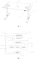
Fig. 1 is a structural schematic diagram of an electric lift platform according to a first embodiment of the present disclosure; -
Fig. 2 is a structural schematic diagram of a controller in the electric lift platform according to the first embodiment of the present disclosure; -
Fig. 3 is a structural schematic diagram of an electric lift platform according to a second embodiment of the present disclosure; and -
Fig. 4 is a structural schematic diagram of a controller and a manipulator in an electric lift platform according to a third embodiment of the present disclosure; - 1. Lifting column; 2. Desktop; 3. Transverse beam; 4. Controller; 41. Power supply module; 42. MCU; 43. Motor driver circuit; 44. Feedback circuit; 45. Data communication port; 5. Manipulator; 6. Multi-axis sensor module; 61. MPU 6050 module; 611. Three-axis accelerometer; 612. Three-axis gyroscope; 62. Central processing unit; 621. Filtering module; 63. Three-axis magnetometer.
- As shown in
Figs. 1 to 2 , the present disclosure discloses an electric lift platform retractable upon hitting an obstruction. In this embodiment, the electric lift platform is an electric liftin desk, such that the platform refers to the desktop of the electric lift desk. The electric lift desk comprises a lifting column 1, adesktop 2, acontroller 4, amanipulator 5, and a multi-axis sensor module 6 for acquiring platform obstruction-hitting data, wherein the multi-axis sensor module 6 acquires variations of motion statuses of thedesktop 2 along different axes, satisfying detection of motion statuses of thedesktop 2 caused by different obstacles at different positions; besides, the detection is not affected by assembly of the lift platform and is less demanding on the installation position. Further, the sensor is not required to directly contact with the stress-bearing surface, and even an impact with a smaller stress can be detected, thereby offering a higher detection sensitivity. Thecontroller 4 comprises apower supply module 41, a maincontrol unit MCU 42, and amotor driver circuit 43, wherein the output end of theMCU 42 is connected to themotor driver circuit 43, and the multi-axis sensor module 6 is connected to the input end of theMCU 42, such that theMCU 42, after having processed the obstruction-hitting data, transmits a control signal to themotor driver circuit 43, and the latter controls the lifting column 1 to execute a corresponding retract action; in this way, safety of the electric lift platform is significantly improved. In this example, the MCU adopts a Freescale HCS08 family microcontroller, which is reliable in motor driver applications; in this way, reliability of the electric lift platform is improved. - In this embodiment, the obstruction-hitting data include accelerations along the X-axis, Y-axis, and Z-axis and/or angular velocities along the three axes; the plane where the
desktop 2 is located is a plane formed between any two of the X-axis, Y-axis, and Z-axis; and the obstruction-hitting data as acquired include the accelerations along the three axes and/or the angular velocities along the three axes;. The three-axis data acquisition offers a higher detection sensitivity. Besides, with the three-axis data, detection can be still implemented even thedesktop 2 does not tilt. With the accelerations along the three axes as an example, wherein the plane formed between X-axis and Y-axis is the plane where thedesktop 2 is located, when thedesktop 2 is vertically stressed and thedesktop 2 only vibrates vertically in the Z-axis direction, the accelerations along the X-axis and Y-axis approach to zero, but the acceleration variation of Z-axis is significant. In this case, thecontroller 4 actuates the lifting column to execute a retract action. With this control manner, the multi-axis sensor module can directly implement sensing without sensing the tilt angle of the platform. Therefore, the actuation manner in this embodiment is not restricted by whether thedesktop 2 tilts, and even thedesktop 2 does not tilt, it can be still sensed that thedesktop 2 hits an obstacle. In this way, more platform accidental situations can be sensed with a higher sense speed, a higher sensitivity, and a higher accuracy; further, due to not relying on a tilt angle of thedesktop 2, the judgement can be performed before tilting of the desktop. - In this embodiment, the multi-axis sensor module 6 is preferably installed in the
controller 4, such that installation of the multi-axis sensor module is not restricted by the fitting degree with other components of the electric lift platform or restricted to a specific stress-bearing mechanism, thereby simplifying the assembly process between the lifting column and an electric push rod, increasing stability of the entire electric lift platform, and improving quality of assembly. Besides; the multi-axis sensor module does not affect installation and assembly of the transmission part of the lift platform per se, does not destroy the simplicity and aesthetics of the appearance of the lift platform, has no extra installation requirement for the user, and simplifies installation steps. - The multi-axis sensor module 6 includes a six-axis sensor module and a central processing unit. The six-axis sensor module has a plurality of models and specifications, e.g., an MPU6050 module, or an LCM20608D module, or an LSM6DSL module. In this example, the six-axis sensor is an MPU6050 module. The
MPU6050 module 61 includes a three-axis accelerometer 611 for acquiring three-axis acceleration data and a three-axis gyroscope 612 for acquiring three-axis angular velocities. By detecting variations of multi-dimensional accelerations and multi-axis angular velocity data at the instant of colliding between thedesktop 2 and an obstacle, the three-axis accelerometer 611 and the three-axis gyroscope 612 realize impact detection; in this way, the detection sensibility is improved and safety of the electric lift platform is enhanced. - It needs to be noted that the three-
axis gyroscope 612 in the MPU6050 module has a very high detection sensitivity, such that when thedesktop 2 hits an obstacle, even thedesktop 2 does not tilt, the three-axis gyroscope 612 can still detect the motion trend of thedesktop 2, causing variation of the three-axis angular velocity data. Likewise, the three-axis accelerometer 611 in the MPU6050 is also very sensitive in detection. Therefore, with such a multi-axis sensor module, the judgment does not rely on a tilt angle of thedesktop 2, which may be made before thedesktop 2 tilts. - In an alternative embodiment, obstruction-hitting data may be acquired independently by the three-
axis accelerometer 611 or the three-axis gyroscope 612 to judge whether the platform hits an obstacle. However, repeated experiments show that joint detection by the three-axis accelerometer 611 and the three-axis gyroscope 612 yields higher sensitivity and accuracy. - In this embodiment, the
central processing unit 62 adopts a highly cost-effective STM32F051K86-model microcomputer. Thecentral processing unit 62 is electrically connected to theMPU6050 module 61. Thecentral processing unit 62 or theMCU 42 further comprises afilter module 621 for filtering the three-axis acceleration data and the three-axis angular velocity data. Through data filtering, a normal lift may be distinguished from an impact, thereby avoiding misjudging a normal lift as an impact, which enhances efficiency of impact reaction. Thecentral processing unit 62 is connected to the input end of the MCU42 to transmit the filtered data to the latter. TheMCU 42, after having processed the obstruction-hitting data, transmits a control signal to amotor driver circuit 43 which then controls the lifting column 1 to execute a corresponding retract action; in this way, the electric lift platform can efficiently and quickly react to the impact to execute a retract action, improving safety of the electric lift platform. - The multi-axis sensor module 6 may further comprise a three-axis magnetometer 63, wherein the three-axis magnetometer 63 is electrically connected to the
MPU6050 module 61, such that the direction data acquired by the three-axis magnetometer 63, together with the three-axis acceleration data and the three-axis angular data in theMUP6050 module 61, are outputted to thecentral processing unit 62. In this embodiment, the three-axis magnetometer 63 adopts a high-precision HMC5883L-model three-axis magnetometer. The HMC5883L-model three-axis magnetometer has been revealed in the patent numberCN 201420544330.2 - In this embodiment, a preset value is set in the MCU. When the variation value of one or more of the accelerations along the X-axis, Y-axis, and Z-axis, and/or one or more of the angular velocities along the X-axis, Y-axis, and Z-axis, in the obstruction-hitting data acquired by the multi-axis sensor, exceeds the preset value by a predetermined margin within a certain time segment, the motor driver circuit controls the lifting column to execute a corresponding retract action. It needs to be noted that because this embodiment adopts a six-axis sensor, there are correspondingly six preset values, i.e., the acceleration of X-axis, the acceleration of Y-axis, and the acceleration of Z-axis, the angular velocity of X-axis, the angular velocity of Y-axis, and the angular velocity of Z-axis, all have their respective preset values. when the variation value of one or more of the six obstruction-hitting data exceeds the corresponding preset value by a preset margin, the motor driver circuit works.
- It needs to be noted that the preset values and preset margins may be customized by the user dependent on different actual use environments. Additionally, in other embodiments, the preset values may also be written into the multi-axis sensor.
- Additionally, it needs to be noted that to determine more accurately whether the desktop hits an obstruction, the comparative analysis may not be restricted to one comparative analysis, but may be performed between multiple time segments, wherein the variation values are compared with corresponding preset values during each time segment. For example, at the instant when the desktop hits an obstacle, its first time segment T1 is relatively short, wherein the variation values of the obstruction-hitting data in T1 are compared with corresponding preset values; after the impact time T1, a second time segment T2 is taken to compare the variation values of the obstruction-hitting data in T2 with the corresponding preset values; so on and so forth. With such multiple times of comparative analysis, the structure can be determined more accurately and misjudgment may be avoided.
- The
controller 4 further comprises afeedback circuit 44 for monitoring stability of the internal circuit of thecontroller 4. Thefeedback circuit 44 constantly monitors the voltage and current statuses inside theentire controller 4, and monitors information such as the motor rotating speed and operating temperature, etc., so as to adopt a corresponding protection measure to handle exceptions, e.g., Stop Error alarm, power outage, etc., which enhances safety of the controller and makes the electric lift platform more reliable. - Specifically, the
filtering module 621 preferably adopts the Kalman filtering algorithm to perform filtering, so as to better solve the problem of Z-axis data drifting and optimize the filtering process, thereby generating a more accurate filtering result and a higher reliability of the function of the electric lift platform to retract upon hitting an obstruction. - The multi-axis sensor module 6 may be fixed inside the
controller 4 via a pin header, which improves detection sensitivity and enhances safety of the electric lift platform. - The
controller 4 is provided on thedesktop 2, such that it does not affect fitting with other components of the electric lift platform; instead, it improves impact detection reliability of the lift platform and greatly enhances safety of the electric lift platform. - It may be understood that the electric lift platform may also be a height adjustable kitchen island and the platform refers to the platform of the kitchen island.
- It may be understood that the electric lift platform may also be a height adjustable tatami, and the platform refers to the board of the tatami.
- It may be understood that the electric lift platform may also be a height adjustable hospital bed, and the platform refers to the bed board of the hospital bed.
- It may be understood that the
filtering module 621 may optionally adopt other algorithms such as margin limiting average filtering algorithm to perform filtering, as long as it can distinguish a normal lift from an impact to avoid misjudging the normal lift as an impact. - It may be understood that the multi-axis sensor module 6 may also be flush-jointed in the
controller 4. - As shown in
Fig. 3 , the second embodiment differs from the first embodiment in that the electric lift platform further includes a transverse beam for supporting the platform. - The
controller 4 is securely threaded to thetransverse beam 3. Such a setting offers an advantage that the multi-axis sensor module 6 may acquire obstruction-hitting data for thedesktop 2 and thetransverse beam 3; besides, the installation position does not affect fitting with other components of the electric lift platform; instead, it improves impact detection reliability of the electric lift platform and significantly enhances safety of the electric lift platform. In this embodiment, thetransverse beam 3 preferably includes two transverse bars, wherein thecontroller 4 is fixed in the space formed between the two transverse bars. It needs to be noted that thetransverse beam 3 is not limited to the shape configuration in this embodiment, but may also be other shape configurations. - It may be understood that the
controller 4 may also be installed on thedesktop 2, as long as the electric lift platform can reliably detect an impact. - As shown in
Fig. 4 , this embodiment differs from the above embodiments in that the multi-axis sensor module is mounted in the manipulator. - A
data communication port 45 is provided on thecontroller 4, and the multi-axis sensor module 6 is provided in themanipulator 5, such that the multi-axis sensor module 6 is electrically connected to theMCU 42 in thecontroller 4 via thedata communication port 45. - Such a setting offers an advantage that installation of the multi-axis sensor module is not restricted by the fitting degree with other components of the electric lift platform or restricted to a specific stress-bearing mechanism thereby simplifying the assembly process between the lifting column and an electric push rod, increasing stability of the entire electric lift platform, and improving quality of assembly. Besides; the multi-axis sensor module does not affect installation and assembly of the transmission part of the lift platform per se, does not destroy the simplicity and aesthetics of the appearance of the lift platform, has no extra installation requirement for the user, and simplifies installation steps.
- Specifically, the multi-axis sensor module is fixed inside the manipulator via a pin header, which improves detection sensitivity and enhances safety of the electric lift platform.
- It may be understood that the multi-axis sensor module is flush-jointed in the manipulator, offering a simple and convenient installation process and a high detection sensitivity.
- This embodiment differs from the first embodiment in that the multi-axis sensor module here is mounted in the lifting column; because the lifting column is fixedly connected to the desktop, after an impact occurs to the desktop, the lifting column will have a corresponding motion trend. When the multi-axis sensor module is installed in the lifting column, a data communication port is provided on the controller; the multi-axis sensor module and the controller are connected via the data communication port. Of course, they may also be connected using a signal line.
- It needs to be noted that the installation position of the multi-axis sensor module is not limited to the embodiments above. In other embodiments, the multi-axis sensor module may be provided as a standalone part between the lifting column and the controller, or may be provided as a standalone part between the manipulator and the controller.
Claims (12)
- An electric lift platform retractable upon hitting an obstruction, comprising:a lifting column (1), a platform (2), a transverse beam (3), a controller (4), and a manipulator (5), wherein the controller (4) comprises a main control unit, MCU (42), and a motor driver circuit (44), an output end of the MCU (42) being connected to the motor driver circuit, wherein the electric lift platform further comprises a multi-axis sensor module (6) for acquiring platform obstruction-hitting data, the multi-axis sensor module (6) being connected to an input end of the MCU (42) such that the MCU (42), after having processed the obstruction-hitting data, transmits a control signal to the motor driver circuit (44), and the latter controls the lifting column (1) to execute a corresponding retract action, the multi-axis sensor module (6) including a central processing unit (62),characterized in thatthe multi-axis sensor module (6) further includes a six-axis sensor module (611, 612), the six-axis sensor module (611, 612) being electrically connected with the central processing unit (62), the central processing unit (62) being connected to the input end of the MCU (42), and wherein the six-axis sensor module (611, 612) includes a three-axis accelerometer (611) configured for acquiring three-axis acceleration data and a three-axis gyroscope (612) configured for acquiring three-axis angular velocity data.
- The electric lift platform according to claim 1, wherein the multi-axis sensor module (6) is provided in the controller
- The electric lift platform according to claim 2, wherein the multi-axis sensor module (6) is fixed inside the controller via a pin header; or, the multi-axis sensor module is flush-jointed to the interior of the controller.
- The electric lift platform retractable according to claim 1, wherein the multi-axis sensor module (6) is provided external to the controller, a data communication port being provided for the controller, the multi-axis sensor module being electrically connected with the MCU via the data communication port.
- The electric lift platform according to claim 4, wherein the multi-axis sensor module (6) is provided inside the manipulator, or provided inside the lifting column, or provided as a standalone part between the lifting column and the controller, or provided as a standalone part between the manipulator and the controller.
- The electric lift platform according to claim 1, wherein the electric lift platform further comprises a transverse beam for supporting the platform, the controller being provided on the transverse beam, or the controller being provided on the platform.
- The electric lift platform according to claim 1, wherein the obstruction-hitting data include accelerations along the X-axis, Y-axis, and Z-axis and/or angular velocities along the three axes, and the plane where the platform is located is a plane formed between any two of the X-axis, Y-axis, and Z-axis.
- The electric lift platform according to claim 7, wherein a preset value is set in the MCU or the multi-axis sensor module (6), the obstruction-hitting data includes the accelerations along the X-axis, Y-axis, and Z-axis and the angular velocities along the X-axis, Y-axis, and Z-axis, wherein when a variation value of one or more of the six values exceeds the preset value by a predetermined margin within a certain time segment, the motor driver circuit controls the lifting column to execute a corresponding retract action.
- The electric lift platform according to claim 1, wherein the six-axis sensor module (6) is an MPU6050 module, or an ICM20608D module, or an LSM6DSL module.
- The electric lift platform retractable according to claim 1, wherein the central processor or the MCU includes a filter module for filtering the three-axis acceleration data and the three-axis angular velocity data.
- The electric lift platform according to claim 1, wherein the multi-axis sensor module (6) further comprises a three-axis magnetometer, the three-axis magnetometer being electrically connected to the six-axis sensor module.
- The electric lift platform according to claim 1, wherein the controller further comprises a feedback circuit configured for monitoring stability of an internal circuit of the controller.
Applications Claiming Priority (2)
| Application Number | Priority Date | Filing Date | Title |
|---|---|---|---|
| CN201720672892.9U CN207115083U (en) | 2017-06-09 | 2017-06-09 | A kind of electric lifting platform that can be retracted that is hampered |
| PCT/CN2018/075013 WO2018223720A1 (en) | 2017-06-09 | 2018-02-02 | Electric lifting platform capable of retracting upon encountering resistance |
Publications (4)
| Publication Number | Publication Date |
|---|---|
| EP3637206A1 EP3637206A1 (en) | 2020-04-15 |
| EP3637206A4 EP3637206A4 (en) | 2021-03-10 |
| EP3637206B1 true EP3637206B1 (en) | 2024-10-16 |
| EP3637206C0 EP3637206C0 (en) | 2024-10-16 |
Family
ID=61594293
Family Applications (1)
| Application Number | Title | Priority Date | Filing Date |
|---|---|---|---|
| EP18813141.1A Active EP3637206B1 (en) | 2017-06-09 | 2018-02-02 | Electric lifting platform capable of retracting upon encountering resistance |
Country Status (5)
| Country | Link |
|---|---|
| US (1) | US11284709B2 (en) |
| EP (1) | EP3637206B1 (en) |
| JP (1) | JP7026703B2 (en) |
| CN (1) | CN207115083U (en) |
| WO (1) | WO2018223720A1 (en) |
Families Citing this family (24)
| Publication number | Priority date | Publication date | Assignee | Title |
|---|---|---|---|---|
| DE112018006985A5 (en) * | 2018-01-31 | 2020-10-08 | Oelschläger Metalltechnik GmbH | ELECTRICALLY HEIGHT-ADJUSTABLE TABLE AND PROCEDURE FOR CONTROLLING THE DESSEL |
| CN109700173A (en) * | 2018-05-31 | 2019-05-03 | 乐歌人体工学科技股份有限公司 | Same table control method |
| CN109031953B (en) * | 2018-07-26 | 2021-10-15 | 上海高适软件有限公司 | Self-learning-based electric lifting table resistance-encountering rollback method and system and lifting equipment |
| CN109452757A (en) * | 2018-12-04 | 2019-03-12 | 嘉兴礼海电气科技有限公司 | One kind being based on electric elevatable table anticollision control system and its collision-proof method |
| US11510487B2 (en) | 2018-12-06 | 2022-11-29 | Zhejiang Jiecang Linear Motion Technology Co., Ltd. | Desktop lifting platform with improved safety |
| CN110040650B (en) * | 2019-02-22 | 2021-02-02 | 乐歌人体工学科技股份有限公司 | Electric lifting platform control method for realizing rollback in case of resistance |
| MX2021013032A (en) * | 2019-04-25 | 2022-02-10 | Ergotron Inc | Height adjustable workstations with zero idle power. |
| CN111184345B (en) * | 2020-03-13 | 2024-06-25 | 常州市凯迪电器股份有限公司 | Control method and control unit for safe operation of electric table |
| USD947579S1 (en) * | 2020-06-15 | 2022-04-05 | zhejiang zhongwei smart furniture Co., LTD | Electric lift table |
| USD950986S1 (en) * | 2020-07-13 | 2022-05-10 | Yajun Hu | Height adjustable desk |
| DE102020211550A1 (en) * | 2020-09-15 | 2022-03-17 | Kesseböhmer Holding Kg | Drive system for moving a height-adjustable tabletop, table with such a drive system and method for detecting a collision of a height-adjustable tabletop |
| CN112731830A (en) * | 2020-12-15 | 2021-04-30 | 天津大学 | Laser Raman spectrometer light path automatic control system based on closed-loop control |
| CN114509723B (en) * | 2021-08-04 | 2025-02-18 | 浙江捷昌线性驱动科技股份有限公司 | Method for detecting the obstructed part of an electric bed capable of retreating when encountering an obstruction |
| USD972342S1 (en) * | 2021-09-22 | 2022-12-13 | Zhejiang Zhongwei Smart Furniture Co., Ltd. | Lifting table |
| USD966752S1 (en) * | 2021-09-24 | 2022-10-18 | Jiangsu Star Intelligent Home Furnishing Co., Ltd | Electric desk |
| USD966016S1 (en) * | 2021-09-24 | 2022-10-11 | Jiangsu Star Intelligent Home Furnishing Co., Ltd | Electric desk |
| USD966751S1 (en) * | 2021-11-04 | 2022-10-18 | Shenzhen Bestqi Innovation Technology Co., Ltd | Computer desk |
| CN114428471B (en) * | 2021-11-29 | 2024-12-17 | 浙江捷昌线性驱动科技股份有限公司 | Safety control system and method for electric furniture controller |
| USD965349S1 (en) * | 2021-12-13 | 2022-10-04 | Shenzhen Bestqi Innovation Technology Co., Ltd | Height adjustable desk |
| CN114352899A (en) * | 2021-12-14 | 2022-04-15 | 深圳市惠康电机制造有限公司 | Multimedia device |
| CN114631687B (en) * | 2022-03-07 | 2023-05-12 | 深圳市瑞必达科技有限公司 | Control method for knocking protection and tilting protection by lifting table without calculating Euler angle |
| USD979988S1 (en) * | 2022-04-19 | 2023-03-07 | Sailvan Times Co., Ltd. | Electric standing desk |
| USD1093025S1 (en) * | 2023-05-16 | 2025-09-16 | Odk Technology Pte. Ltd. | Desk |
| CN116953285A (en) * | 2023-06-28 | 2023-10-27 | 乐歌人体工学科技股份有限公司 | Human body detection method and system based on six-axis sensor |
Family Cites Families (37)
| Publication number | Priority date | Publication date | Assignee | Title |
|---|---|---|---|---|
| US6352037B1 (en) * | 2000-02-28 | 2002-03-05 | Suspa Incorporated | Position sensor holder and cover for motor drive unit |
| GB0506691D0 (en) * | 2005-04-01 | 2005-05-11 | Pegasus Ltd | Height-adjustable bed |
| US8522695B2 (en) * | 2006-05-01 | 2013-09-03 | Linak A/S | Electrically adjustable piece of furniture |
| DE102006038558A1 (en) * | 2006-08-17 | 2008-04-30 | Vibradorm Gmbh | Electrically adjustable furniture's e.g. office furniture, drive control arrangement, has motor that is controlled with acceleration measured from acceleration sensor, such that movement of furniture can be stopped |
| EP1891872B1 (en) * | 2006-08-24 | 2010-06-02 | Kesseböhmer Produktions GmbH + Co. KG | Device and process for detection of collisions for furniture |
| US20090044334A1 (en) * | 2007-08-13 | 2009-02-19 | Valence Broadband, Inc. | Automatically adjusting patient platform support height in response to patient related events |
| CN201605989U (en) * | 2010-03-09 | 2010-10-13 | 漳州优耐特电子制造有限公司 | Rolling door baffle rebounding device |
| DE102011007540A1 (en) * | 2011-04-15 | 2012-10-18 | Kesseböhmer Produktions GmbH & Co. KG | Calibratable telescope column, furniture with calibratable telescope column, and method for calibration of a telescope column |
| EP2790631B1 (en) * | 2011-12-16 | 2017-02-01 | Stryker Corporation | Patient support overload or obstruction detection |
| US9486070B2 (en) * | 2012-10-10 | 2016-11-08 | Stirworks Inc. | Height-adjustable support surface and system for encouraging human movement and promoting wellness |
| US10827829B1 (en) * | 2012-10-10 | 2020-11-10 | Steelcase Inc. | Height adjustable support surface and system for encouraging human movement and promoting wellness |
| WO2015058768A1 (en) * | 2013-05-10 | 2015-04-30 | Linak A/S | Height adjustable table |
| JP6579621B2 (en) | 2013-12-13 | 2019-09-25 | 雅文 山▲崎▼ | Treatment table |
| KR101453054B1 (en) * | 2014-06-17 | 2014-10-23 | 김재형 | Hybrid mini pc smart table system |
| CN204085526U (en) | 2014-09-22 | 2015-01-07 | 南京信息工程大学 | A kind of digital electronic compass |
| US10206834B2 (en) * | 2014-12-11 | 2019-02-19 | Stryker Corporation | Obstruction detection system and method |
| CN104695846B (en) * | 2015-02-12 | 2017-09-12 | 博慧电子科技(漳州)有限公司 | Resistance rebound device for rolling door based on gravity accelerometer |
| DE102015002044A1 (en) * | 2015-02-12 | 2016-08-18 | Eberhard Lenz | furniture system |
| KR102053015B1 (en) * | 2015-04-23 | 2020-01-08 | 티모션 테크놀로지 코., 엘티디. | Electrical Adjustable Table and Control Method for Electrical Adjustable Table |
| US20160353880A1 (en) * | 2015-06-03 | 2016-12-08 | Tome, Inc. | System And Method For Sensing Obstructions Of Sensors Used With An Adjustable Height Work Desk |
| US10406045B2 (en) * | 2015-06-22 | 2019-09-10 | Stryker Corporation | Patient support apparatuses with navigation and guidance systems |
| GB2541517B (en) * | 2015-07-01 | 2021-04-21 | Fellowes Inc | Variable height desktop workstation system |
| TWI552701B (en) * | 2015-08-04 | 2016-10-11 | Quan-Hang Shi | Synchronous motion control system and method for double electric bed |
| CN205477329U (en) * | 2015-08-04 | 2016-08-17 | 漳州市雷奥德机电设备有限公司 | Rolling door machine chance through current detection hinders bounce -back device |
| US20170251806A1 (en) * | 2016-03-07 | 2017-09-07 | Scott Newman | Height-adjustable table or desk |
| JP6668142B2 (en) * | 2016-03-30 | 2020-03-18 | 株式会社オカムラ | Furniture with lifting function |
| CN205691988U (en) * | 2016-06-12 | 2016-11-16 | 深圳市集美华太科技有限公司 | A kind of electric elevatable table is hampered bounce-back controller |
| CN106249645B (en) * | 2016-08-05 | 2019-08-20 | 浙江捷昌线性驱动科技股份有限公司 | Built-in same table control system based on LIN communication |
| CN106923492A (en) * | 2017-03-30 | 2017-07-07 | 上海谛明家具有限公司 | Intelligent health liftable office desk and chair system |
| US10791826B2 (en) * | 2017-03-31 | 2020-10-06 | Twin-Star International, Inc. | Adjustable height desk system |
| DK201700305A1 (en) * | 2017-05-15 | 2018-11-23 | Linak A/S | Height-adjustable table |
| WO2018210387A1 (en) * | 2017-05-15 | 2018-11-22 | Linak A/S | Height-adjustable table |
| US10568418B2 (en) * | 2017-09-18 | 2020-02-25 | Fellowes, Inc. | Variable height platform system |
| US20210000250A1 (en) * | 2018-02-08 | 2021-01-07 | Linak A/S | Height-adjustable table |
| US20190328129A1 (en) * | 2018-04-30 | 2019-10-31 | QualGear LLC | Automatically adjustable desk and tabletop desk with presence detection, usage tracking and methods thereof |
| CN110250739A (en) * | 2019-04-18 | 2019-09-20 | 美国乐歌有限公司 | Control system and method for electric lift table that realizes retreat in case of resistance |
| CN110338556B (en) * | 2019-07-10 | 2025-11-14 | 乐歌人体工学科技股份有限公司 | Electric height-adjustable desk and its control method |
-
2017
- 2017-06-09 CN CN201720672892.9U patent/CN207115083U/en active Active
-
2018
- 2018-02-02 WO PCT/CN2018/075013 patent/WO2018223720A1/en not_active Ceased
- 2018-02-02 JP JP2019568090A patent/JP7026703B2/en active Active
- 2018-02-02 EP EP18813141.1A patent/EP3637206B1/en active Active
- 2018-02-02 US US16/620,527 patent/US11284709B2/en active Active
Also Published As
| Publication number | Publication date |
|---|---|
| EP3637206A1 (en) | 2020-04-15 |
| CN207115083U (en) | 2018-03-16 |
| WO2018223720A1 (en) | 2018-12-13 |
| US20210145164A1 (en) | 2021-05-20 |
| US11284709B2 (en) | 2022-03-29 |
| JP2020528593A (en) | 2020-09-24 |
| EP3637206C0 (en) | 2024-10-16 |
| EP3637206A4 (en) | 2021-03-10 |
| JP7026703B2 (en) | 2022-02-28 |
Similar Documents
| Publication | Publication Date | Title |
|---|---|---|
| US11284709B2 (en) | Electric lifting platform retractable upon hitting obstruction | |
| EP3574800B1 (en) | Lifting desk control method | |
| JP2020528593A5 (en) | ||
| CN106272408A (en) | The method that the controller of robot is switched to manual guidance operational mode | |
| US10840837B2 (en) | Power seat system for sensing motor reverse rotation and method thereof | |
| US10538286B2 (en) | Electric balancing swing car | |
| EP3892153B1 (en) | Electric lift table-based anti-collision control system and anti-collision method therefor | |
| EP3878312B1 (en) | Unit for controlling safe operation of an electric table | |
| CN115256468B (en) | A state detection and standing planning method for a humanoid robot after falling down | |
| CN110215080B (en) | Electric bed control method for preventing misoperation and electric bed | |
| CN212088601U (en) | Control unit for safe operation of electric table | |
| CN114228367A (en) | Myopia prevention and control intelligent writing tool | |
| CN217465915U (en) | Liquid level detection device | |
| CN111331631A (en) | Anti-collision sensor for robot | |
| CN113040753A (en) | Sitting posture monitoring system | |
| KR20160127418A (en) | Attitude control apparatus with a sensor of the v-shape | |
| CN212267720U (en) | Foot-controlled electric balance car | |
| CN212340069U (en) | Multifunctional target | |
| CN208672608U (en) | A kind of drug dissolution instrument lifting column anti-collision protection device | |
| CN113511020A (en) | Posture correcting pen for correcting pen holding mode and sitting posture | |
| CN114117321A (en) | Hand clamping prevention system of electric table | |
| CN209182946U (en) | A kind of Multifunctional security device | |
| KR101314943B1 (en) | Apparatus and method for processing input data of touch screen using moving information | |
| TWI896501B (en) | Obstacle protection structure of lifting column | |
| US20160182043A1 (en) | Context-Aware Electronic Apparatus, System and Methods thereof |
Legal Events
| Date | Code | Title | Description |
|---|---|---|---|
| STAA | Information on the status of an ep patent application or granted ep patent |
Free format text: STATUS: THE INTERNATIONAL PUBLICATION HAS BEEN MADE |
|
| PUAI | Public reference made under article 153(3) epc to a published international application that has entered the european phase |
Free format text: ORIGINAL CODE: 0009012 |
|
| STAA | Information on the status of an ep patent application or granted ep patent |
Free format text: STATUS: REQUEST FOR EXAMINATION WAS MADE |
|
| 17P | Request for examination filed |
Effective date: 20200109 |
|
| AK | Designated contracting states |
Kind code of ref document: A1 Designated state(s): AL AT BE BG CH CY CZ DE DK EE ES FI FR GB GR HR HU IE IS IT LI LT LU LV MC MK MT NL NO PL PT RO RS SE SI SK SM TR |
|
| AX | Request for extension of the european patent |
Extension state: BA ME |
|
| RIN1 | Information on inventor provided before grant (corrected) |
Inventor name: TAN, YUCHEN Inventor name: CHEN, XUELI Inventor name: LU, XIAOJIAN |
|
| RIN1 | Information on inventor provided before grant (corrected) |
Inventor name: LU, XIAOJIAN Inventor name: TAN, YUCHEN Inventor name: CHEN, XUELI |
|
| DAV | Request for validation of the european patent (deleted) | ||
| DAX | Request for extension of the european patent (deleted) | ||
| A4 | Supplementary search report drawn up and despatched |
Effective date: 20210210 |
|
| RIC1 | Information provided on ipc code assigned before grant |
Ipc: A47B 9/00 20060101ALI20210204BHEP Ipc: G05B 9/02 20060101ALI20210204BHEP Ipc: G05B 19/042 20060101AFI20210204BHEP Ipc: A47C 19/04 20060101ALN20210204BHEP |
|
| STAA | Information on the status of an ep patent application or granted ep patent |
Free format text: STATUS: EXAMINATION IS IN PROGRESS |
|
| 17Q | First examination report despatched |
Effective date: 20220609 |
|
| RIC1 | Information provided on ipc code assigned before grant |
Ipc: A47C 19/04 20060101ALN20240611BHEP Ipc: A47B 9/00 20060101ALI20240611BHEP Ipc: G05B 9/02 20060101ALI20240611BHEP Ipc: G05B 19/042 20060101AFI20240611BHEP |
|
| GRAP | Despatch of communication of intention to grant a patent |
Free format text: ORIGINAL CODE: EPIDOSNIGR1 |
|
| STAA | Information on the status of an ep patent application or granted ep patent |
Free format text: STATUS: GRANT OF PATENT IS INTENDED |
|
| RIC1 | Information provided on ipc code assigned before grant |
Ipc: A47C 19/04 20060101ALN20240710BHEP Ipc: A47B 9/00 20060101ALI20240710BHEP Ipc: G05B 9/02 20060101ALI20240710BHEP Ipc: G05B 19/042 20060101AFI20240710BHEP |
|
| RIC1 | Information provided on ipc code assigned before grant |
Ipc: A47C 19/04 20060101ALN20240718BHEP Ipc: A47B 9/00 20060101ALI20240718BHEP Ipc: G05B 9/02 20060101ALI20240718BHEP Ipc: G05B 19/042 20060101AFI20240718BHEP |
|
| INTG | Intention to grant announced |
Effective date: 20240731 |
|
| RAP3 | Party data changed (applicant data changed or rights of an application transferred) |
Owner name: ZHEJIANG JIECANG LINEAR MOTION TECHNOLOGY CO., LTD |
|
| GRAS | Grant fee paid |
Free format text: ORIGINAL CODE: EPIDOSNIGR3 |
|
| GRAA | (expected) grant |
Free format text: ORIGINAL CODE: 0009210 |
|
| STAA | Information on the status of an ep patent application or granted ep patent |
Free format text: STATUS: THE PATENT HAS BEEN GRANTED |
|
| AK | Designated contracting states |
Kind code of ref document: B1 Designated state(s): AL AT BE BG CH CY CZ DE DK EE ES FI FR GB GR HR HU IE IS IT LI LT LU LV MC MK MT NL NO PL PT RO RS SE SI SK SM TR |
|
| REG | Reference to a national code |
Ref country code: GB Ref legal event code: FG4D |
|
| REG | Reference to a national code |
Ref country code: CH Ref legal event code: EP |
|
| REG | Reference to a national code |
Ref country code: IE Ref legal event code: FG4D |
|
| REG | Reference to a national code |
Ref country code: DE Ref legal event code: R096 Ref document number: 602018075567 Country of ref document: DE |
|
| U01 | Request for unitary effect filed |
Effective date: 20241106 |
|
| U07 | Unitary effect registered |
Designated state(s): AT BE BG DE DK EE FI FR IT LT LU LV MT NL PT RO SE SI Effective date: 20241114 |
|
| U20 | Renewal fee for the european patent with unitary effect paid |
Year of fee payment: 8 Effective date: 20250129 |
|
| PG25 | Lapsed in a contracting state [announced via postgrant information from national office to epo] |
Ref country code: HR Free format text: LAPSE BECAUSE OF FAILURE TO SUBMIT A TRANSLATION OF THE DESCRIPTION OR TO PAY THE FEE WITHIN THE PRESCRIBED TIME-LIMIT Effective date: 20241016 Ref country code: IS Free format text: LAPSE BECAUSE OF FAILURE TO SUBMIT A TRANSLATION OF THE DESCRIPTION OR TO PAY THE FEE WITHIN THE PRESCRIBED TIME-LIMIT Effective date: 20250216 |
|
| PG25 | Lapsed in a contracting state [announced via postgrant information from national office to epo] |
Ref country code: ES Free format text: LAPSE BECAUSE OF FAILURE TO SUBMIT A TRANSLATION OF THE DESCRIPTION OR TO PAY THE FEE WITHIN THE PRESCRIBED TIME-LIMIT Effective date: 20241016 |
|
| PG25 | Lapsed in a contracting state [announced via postgrant information from national office to epo] |
Ref country code: NO Free format text: LAPSE BECAUSE OF FAILURE TO SUBMIT A TRANSLATION OF THE DESCRIPTION OR TO PAY THE FEE WITHIN THE PRESCRIBED TIME-LIMIT Effective date: 20250116 |
|
| PG25 | Lapsed in a contracting state [announced via postgrant information from national office to epo] |
Ref country code: GR Free format text: LAPSE BECAUSE OF FAILURE TO SUBMIT A TRANSLATION OF THE DESCRIPTION OR TO PAY THE FEE WITHIN THE PRESCRIBED TIME-LIMIT Effective date: 20250117 |
|
| PG25 | Lapsed in a contracting state [announced via postgrant information from national office to epo] |
Ref country code: PL Free format text: LAPSE BECAUSE OF FAILURE TO SUBMIT A TRANSLATION OF THE DESCRIPTION OR TO PAY THE FEE WITHIN THE PRESCRIBED TIME-LIMIT Effective date: 20241016 |
|
| PG25 | Lapsed in a contracting state [announced via postgrant information from national office to epo] |
Ref country code: RS Free format text: LAPSE BECAUSE OF FAILURE TO SUBMIT A TRANSLATION OF THE DESCRIPTION OR TO PAY THE FEE WITHIN THE PRESCRIBED TIME-LIMIT Effective date: 20250116 |
|
| PG25 | Lapsed in a contracting state [announced via postgrant information from national office to epo] |
Ref country code: SM Free format text: LAPSE BECAUSE OF FAILURE TO SUBMIT A TRANSLATION OF THE DESCRIPTION OR TO PAY THE FEE WITHIN THE PRESCRIBED TIME-LIMIT Effective date: 20241016 |
|
| PG25 | Lapsed in a contracting state [announced via postgrant information from national office to epo] |
Ref country code: SK Free format text: LAPSE BECAUSE OF FAILURE TO SUBMIT A TRANSLATION OF THE DESCRIPTION OR TO PAY THE FEE WITHIN THE PRESCRIBED TIME-LIMIT Effective date: 20241016 |
|
| PG25 | Lapsed in a contracting state [announced via postgrant information from national office to epo] |
Ref country code: CZ Free format text: LAPSE BECAUSE OF FAILURE TO SUBMIT A TRANSLATION OF THE DESCRIPTION OR TO PAY THE FEE WITHIN THE PRESCRIBED TIME-LIMIT Effective date: 20241016 |
|
| PLBE | No opposition filed within time limit |
Free format text: ORIGINAL CODE: 0009261 |
|
| STAA | Information on the status of an ep patent application or granted ep patent |
Free format text: STATUS: NO OPPOSITION FILED WITHIN TIME LIMIT |
|
| PG25 | Lapsed in a contracting state [announced via postgrant information from national office to epo] |
Ref country code: MC Free format text: LAPSE BECAUSE OF FAILURE TO SUBMIT A TRANSLATION OF THE DESCRIPTION OR TO PAY THE FEE WITHIN THE PRESCRIBED TIME-LIMIT Effective date: 20241016 |
|
| 26N | No opposition filed |
Effective date: 20250717 |
|
| REG | Reference to a national code |
Ref country code: CH Ref legal event code: PL |
|
| PG25 | Lapsed in a contracting state [announced via postgrant information from national office to epo] |
Ref country code: CH Free format text: LAPSE BECAUSE OF NON-PAYMENT OF DUE FEES Effective date: 20250228 |
|
| GBPC | Gb: european patent ceased through non-payment of renewal fee |
Effective date: 20250202 |
|
| PG25 | Lapsed in a contracting state [announced via postgrant information from national office to epo] |
Ref country code: GB Free format text: LAPSE BECAUSE OF NON-PAYMENT OF DUE FEES Effective date: 20250202 |
|
| PG25 | Lapsed in a contracting state [announced via postgrant information from national office to epo] |
Ref country code: IE Free format text: LAPSE BECAUSE OF NON-PAYMENT OF DUE FEES Effective date: 20250202 |
|
| U20 | Renewal fee for the european patent with unitary effect paid |
Year of fee payment: 9 Effective date: 20260107 |
|
| PG25 | Lapsed in a contracting state [announced via postgrant information from national office to epo] |
Ref country code: CY Free format text: LAPSE BECAUSE OF FAILURE TO SUBMIT A TRANSLATION OF THE DESCRIPTION OR TO PAY THE FEE WITHIN THE PRESCRIBED TIME-LIMIT Effective date: 20241016 |
|
| PG25 | Lapsed in a contracting state [announced via postgrant information from national office to epo] |
Ref country code: TR Free format text: LAPSE BECAUSE OF FAILURE TO SUBMIT A TRANSLATION OF THE DESCRIPTION OR TO PAY THE FEE WITHIN THE PRESCRIBED TIME-LIMIT Effective date: 20241016 |