EP3637162A1 - Optical fiber coupler - Google Patents
Optical fiber coupler Download PDFInfo
- Publication number
- EP3637162A1 EP3637162A1 EP18813639.4A EP18813639A EP3637162A1 EP 3637162 A1 EP3637162 A1 EP 3637162A1 EP 18813639 A EP18813639 A EP 18813639A EP 3637162 A1 EP3637162 A1 EP 3637162A1
- Authority
- EP
- European Patent Office
- Prior art keywords
- optical fiber
- coupler
- adhesive
- coupler portion
- fiber coupler
- Prior art date
- Legal status (The legal status is an assumption and is not a legal conclusion. Google has not performed a legal analysis and makes no representation as to the accuracy of the status listed.)
- Granted
Links
Images




Classifications
-
- G—PHYSICS
- G02—OPTICS
- G02B—OPTICAL ELEMENTS, SYSTEMS OR APPARATUS
- G02B6/00—Light guides; Structural details of arrangements comprising light guides and other optical elements, e.g. couplings
- G02B6/24—Coupling light guides
- G02B6/26—Optical coupling means
- G02B6/28—Optical coupling means having data bus means, i.e. plural waveguides interconnected and providing an inherently bidirectional system by mixing and splitting signals
- G02B6/2804—Optical coupling means having data bus means, i.e. plural waveguides interconnected and providing an inherently bidirectional system by mixing and splitting signals forming multipart couplers without wavelength selective elements, e.g. "T" couplers, star couplers
- G02B6/2821—Optical coupling means having data bus means, i.e. plural waveguides interconnected and providing an inherently bidirectional system by mixing and splitting signals forming multipart couplers without wavelength selective elements, e.g. "T" couplers, star couplers using lateral coupling between contiguous fibres to split or combine optical signals
- G02B6/2843—Optical coupling means having data bus means, i.e. plural waveguides interconnected and providing an inherently bidirectional system by mixing and splitting signals forming multipart couplers without wavelength selective elements, e.g. "T" couplers, star couplers using lateral coupling between contiguous fibres to split or combine optical signals the couplers having polarisation maintaining or holding properties
-
- G—PHYSICS
- G02—OPTICS
- G02B—OPTICAL ELEMENTS, SYSTEMS OR APPARATUS
- G02B6/00—Light guides; Structural details of arrangements comprising light guides and other optical elements, e.g. couplings
- G02B6/02—Optical fibres with cladding with or without a coating
- G02B6/024—Optical fibres with cladding with or without a coating with polarisation maintaining properties
-
- G—PHYSICS
- G02—OPTICS
- G02B—OPTICAL ELEMENTS, SYSTEMS OR APPARATUS
- G02B6/00—Light guides; Structural details of arrangements comprising light guides and other optical elements, e.g. couplings
- G02B6/24—Coupling light guides
- G02B6/26—Optical coupling means
- G02B6/28—Optical coupling means having data bus means, i.e. plural waveguides interconnected and providing an inherently bidirectional system by mixing and splitting signals
- G02B6/2804—Optical coupling means having data bus means, i.e. plural waveguides interconnected and providing an inherently bidirectional system by mixing and splitting signals forming multipart couplers without wavelength selective elements, e.g. "T" couplers, star couplers
- G02B6/2821—Optical coupling means having data bus means, i.e. plural waveguides interconnected and providing an inherently bidirectional system by mixing and splitting signals forming multipart couplers without wavelength selective elements, e.g. "T" couplers, star couplers using lateral coupling between contiguous fibres to split or combine optical signals
- G02B6/2835—Optical coupling means having data bus means, i.e. plural waveguides interconnected and providing an inherently bidirectional system by mixing and splitting signals forming multipart couplers without wavelength selective elements, e.g. "T" couplers, star couplers using lateral coupling between contiguous fibres to split or combine optical signals formed or shaped by thermal treatment, e.g. couplers
-
- G—PHYSICS
- G02—OPTICS
- G02B—OPTICAL ELEMENTS, SYSTEMS OR APPARATUS
- G02B6/00—Light guides; Structural details of arrangements comprising light guides and other optical elements, e.g. couplings
- G02B6/24—Coupling light guides
- G02B6/36—Mechanical coupling means
-
- G—PHYSICS
- G02—OPTICS
- G02B—OPTICAL ELEMENTS, SYSTEMS OR APPARATUS
- G02B6/00—Light guides; Structural details of arrangements comprising light guides and other optical elements, e.g. couplings
- G02B6/24—Coupling light guides
- G02B6/36—Mechanical coupling means
- G02B6/3628—Mechanical coupling means for mounting fibres to supporting carriers
- G02B6/3632—Mechanical coupling means for mounting fibres to supporting carriers characterised by the cross-sectional shape of the mechanical coupling means
- G02B6/3636—Mechanical coupling means for mounting fibres to supporting carriers characterised by the cross-sectional shape of the mechanical coupling means the mechanical coupling means being grooves
-
- G—PHYSICS
- G02—OPTICS
- G02B—OPTICAL ELEMENTS, SYSTEMS OR APPARATUS
- G02B6/00—Light guides; Structural details of arrangements comprising light guides and other optical elements, e.g. couplings
- G02B6/24—Coupling light guides
- G02B6/255—Splicing of light guides, e.g. by fusion or bonding
- G02B6/2552—Splicing of light guides, e.g. by fusion or bonding reshaping or reforming of light guides for coupling using thermal heating, e.g. tapering, forming of a lens on light guide ends
-
- G—PHYSICS
- G02—OPTICS
- G02B—OPTICAL ELEMENTS, SYSTEMS OR APPARATUS
- G02B6/00—Light guides; Structural details of arrangements comprising light guides and other optical elements, e.g. couplings
- G02B6/24—Coupling light guides
- G02B6/26—Optical coupling means
- G02B6/28—Optical coupling means having data bus means, i.e. plural waveguides interconnected and providing an inherently bidirectional system by mixing and splitting signals
- G02B6/2804—Optical coupling means having data bus means, i.e. plural waveguides interconnected and providing an inherently bidirectional system by mixing and splitting signals forming multipart couplers without wavelength selective elements, e.g. "T" couplers, star couplers
- G02B6/2856—Optical coupling means having data bus means, i.e. plural waveguides interconnected and providing an inherently bidirectional system by mixing and splitting signals forming multipart couplers without wavelength selective elements, e.g. "T" couplers, star couplers formed or shaped by thermal heating means, e.g. splitting, branching and/or combining elements
Definitions
- the present invention relates to an optical fiber coupler for separating and combining light between a plurality of optical fibers.
- a middle portion of each of the plurality of optical fibers is heated to melt a cladding of the optical fiber so that the middle portion may be stretched and joined to form a coupler portion.
- the coupler portion is, for example, inserted into a groove of a substrate, and is fixed inside the groove with an adhesive (see, for example, PATENT LITERATURE 1).
- the optical fiber coupler does not consider factors other than the variation of optical insertion loss.
- the optical fiber coupler according to the present invention has been invented in view of such circumstances.
- An object of the present invention is to suppress the variation of polarization state of the light passing through the coupler portion.
- An optical fiber coupler includes: a substrate having a groove; a coupler portion which is inserted into the groove and to which a middle portion of each of optical fibers is joined; and an adhesive for bonding the coupler portion to the substrate.
- Shore D hardness of the adhesive is 10 to 35.
- a viscosity of the adhesive is 5000 to 15000 mPa ⁇ s.
- an absolute value of variation range of the azimuth angle with respect to temperature change of 5 to 75°C is 10 degrees or less.
- optical fiber coupler it is possible to suppress the variation of the polarization state of the light passing through the coupler portion by setting Shore D hardness of the adhesive to 10 to 35.
- Fig. 1 is a cross-sectional view schematically showing the optical fiber coupler 1.
- Fig. 2 is a plan view schematically showing a substrate 2 and a coupler portion 13.
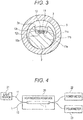
- Fig. 3 is a schematic cross-sectional view taken along line III-III shown in Fig. 1 .
- the optical fiber coupler 1 includes a columnar substrate 2. As a material of the substrate 2, quartz, Invar, Kovar, or the like can be used. In this example, quartz is used.
- the substrate 2 is formed with a groove 2a in its longitudinal direction.
- the coupler portion 13 is inserted into the groove 2a.
- the coupler portion 13 includes a first optical fiber 11 and a second optical fiber 12.
- the first optical fiber 11 includes a core 11a, a cladding 11b that covers a periphery of the core 11a, and a covering portion 11c that covers a periphery of the cladding 11b.
- the second optical fiber 12 includes a core 12a, a cladding 12b that covers the periphery of the core 12a, and a covering portion 12c that covers the periphery of the cladding 12b.
- the claddings 11b and 12b are washed with alcohol or the like.
- middle portions of the first optical fiber 11 and the second optical fiber 12 are heated to melt the claddings 11b and 12b of the first optical fiber 11 and the second optical fiber 12 so that the middle portions may be stretched and joined to form the coupler portion 13.
- the coupler portion 13 may include three or more optical fibers.
- a ratio (branching ratio) between an amount of light passing through the first optical fiber 11 and an amount of light passing through the second optical fiber 12 is a predetermined ratio. For example, when the branching ratio is set to 50:50, 50% of the amount of light introduced into the first optical fiber 11 moves to the second optical fiber 12 through the coupler portion 13.
- Adhesives 3 are respectively provided at two locations of the groove 2a.
- the adhesive 3 includes, for example, a visible light curable resin material or an ultraviolet curable resin material, and includes an epoxy resin material or an acrylate resin material.
- the adhesives 3 are arranged at both end portions of the groove 2a.
- Shore D hardness of the cured adhesive 3 is, for example, 10 to 35, and preferably 15 to 35. If the Shore D hardness is less than 10, when environmental temperature rises, the adhesive 3 is too soft and the coupler portion 13 is easily deformed. If the Shore D hardness exceeds 35, stress tends to concentrate on a part of the coupler portion 13 and the coupler portion 13 is easily distorted. When distortion occurs in the coupler portion 13, polarization state of the light passing through the coupler portion 13 is likely to vary.
- a viscosity of the adhesive 3 before curing is, for example, 5000 to 15000 mPa ⁇ s.
- the viscosity is less than 5000 mPa ⁇ s, the adhesive 3 spreads too much into the groove 2a due to capillary action, and an area of the adhesive 3 adhering to the coupler portion 13 is too large.
- the viscosity is more than 15000 mPa ⁇ s, the adhesive 3 is too hard and it is difficult to apply the adhesive 3 to the coupler portion 13 in the groove 2a.
- the adhesives 3 are respectively provided at both end portions of the groove 2a.
- the adhesive 3 fixes the covering portions 11c and 12c of the first optical fiber 11 and the second optical fiber 12 and glass portions of the first optical fiber 11 and the second optical fiber 12 from which the covering portions 11c and 12c are removed (portions near both ends of the coupler portion 13 of the claddings 11b, 12b and the cores 11a, 12a and where the first optical fiber 11 and the second optical fiber 12 are not thinned) to the groove 2a.
- the coupler portion 13 and the substrate 2 are housed in a protective cylinder 5 made of a metal member, and are fixed to the protective cylinder 5 with an adhesive.
- a material of the protective cylinder 5 SUS, Invar, Kovar, or the like can be used. SUS is used in the example.
- Both end portions of the protective cylinder 5 are sealed with a sealing portion 6.
- the sealing portion 6 contains, for example, a silicone resin material.
- the first optical fiber 11 and the second optical fiber 12 penetrate the sealing portion 6 and protrude outwardly.
- Fig. 4 is a block diagram schematically showing a configuration for measuring temperature dependence of the polarization state.
- the optical fiber coupler 1 is provided in a heating/cooling device 20.
- the heating/cooling device 20 includes a Peltier element.
- a light source 21 is attached to one end portion of the first optical fiber 11, and a power meter 22 is attached to the other end portion.
- the power meter 22 measures the amount of light that has passed through the coupler portion 13 in the first optical fiber 11.
- the power meter 22 can measure insertion loss of the light with respect to temperature change.
- a polarimeter 23 is attached to the other end portion.
- a free space polarimeter "PAX5710 series” manufactured by Thorlabs, Inc. can be used.
- PAN5710IR-T has been used.
- the polarimeter 23 can measure the variation of the polarization state of the light that has passed through the coupler portion 13 with respect to temperature change.
- Fig. 5 is a diagram schematically showing a locus of an electric field vector projected on an XY plane when elliptically polarized light travels in Z direction.
- X-axis and Y-axis are perpendicular to each other.
- Z-axis is perpendicular to the X-axis and the Y-axis and extends in a direction perpendicular to a paper surface.
- the light that has passed through the coupler portion 13 travels with elliptical polarization.
- the locus of the electric field vector projected on the XY plane is an ellipse 30 as shown in Fig. 5 .
- an angle formed by a major axis 31 of the ellipse 30 and the X-axis that is, an azimuth angle
- ⁇ an angle formed by a major axis 31 of the ellipse 30 and the X-axis, that is, an azimuth angle
- ⁇ an angle between a line segment 33 connecting an intersection of the ellipse 30 and the major axis 31 and an intersection of the ellipse 30 and a minor axis 32, and the major axis 31, that is, an ellipticity angle
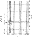
- Fig. 6 is a graph showing the azimuth angle ⁇ measured over time by the polarimeter 23.
- Fig. 7 is a graph showing the ellipticity angle ⁇ measured over time by the polarimeter 23.
- a trace 50 shows a measurement result for the optical fiber coupler 1 using the adhesive 3 having a Shore D hardness of 90.
- a trace 51 shows a measurement result for the optical fiber coupler 1 using the adhesive 3 having a Shore D hardness of 20.
- Traces 52 and 53 show measurement results for the optical fiber coupler 1 using the adhesive 3 having a Shore D hardness of 32.
- a temperature at start of measurement is 25°C.
- the temperature of the heating/cooling device 20 is changed to 5°C, when 300 seconds have elapsed, the temperature of the heating/cooling device 20 is changed to 75°C, and when 500 seconds have elapsed, the temperature of the heating/cooling device 20 is changed to 25°C.
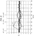
- Fig. 8 is a graph showing a variation value ⁇ of the azimuth angle ⁇ with reference to a value at the start of measurement.
- the variation value ⁇ is in a range of -1 to +1 degree.
- the variation value ⁇ is in the range of -2 to +3 degrees.
- Fig. 9 is a graph showing a variation value ⁇ of the ellipticity angle ⁇ with reference to the value at the start of measurement. As shown by the trace 51 of Fig. 9 , when the adhesive 3 having a Shore D hardness of 20 is used, the variation value ⁇ is within the range of -4 to 2 degrees. As shown by the traces 52 and 53 of Fig. 9 , the variation value ⁇ is within the range of -4 to +4 degrees.
- the azimuth angle ⁇ and the ellipticity angle ⁇ hardly vary. That is, it is possible to suppress the variation of the polarization state with respect to temperature change in the light passing through the coupler portion 13.
- the viscosity of the adhesive 3 is set to 5000 to 15000 mPa ⁇ s, it is possible to prevent the adhesive 3 from adhering to unnecessary portions of the coupler portion 13. Further, the adhesive 3 can be smoothly applied to the coupler portion 13 in the groove 2a. Therefore, manufacturing operation of the optical fiber coupler 1 can be performed smoothly.
- absolute values of the variation ranges of the azimuth angle ⁇ and the ellipticity angle ⁇ are desirably 10 degrees or less, and more desirably 5 degrees or less.
- the absolute value of the variation range of the azimuth angle ⁇ is 3 degrees or less and the absolute value of the variation range of the ellipticity angle ⁇ is 4 degrees or less.
- the optical fiber coupler 1 can be used in an optical interferometer that requires stability of polarization characteristics.
- the optical fiber coupler 1 is used, for example, in an apparatus using OCT (Optical Coherence Tomography).
- OCT Optical Coherence Tomography
- the apparatus is provided with a polarization controller.
- degree of polarization is adjusted by operating the polarization controller depending on the temperature of an environment where the apparatus is installed.
- the polarization controller is driven manually, user operation is required. However, a user may forget the operation.
- the polarization state of the optical fiber coupler 1 has changed, and thus there has been a problem in using the apparatus.
- the absolute values of the variation ranges of the azimuth angle ⁇ and the ellipticity angle ⁇ with respect to temperature change are 10 degrees or less. Therefore, once the polarization is adjusted, it is not necessary to perform readjustment due to the change in polarization by the temperature change, so that convenience for the user can be improved.
- the absolute values of the variation ranges of the azimuth angle ⁇ and the ellipticity angle ⁇ are 10 degrees or less. That is, the variation of the polarization state can be suppressed at the environmental temperature assumed to be normally used.
- optical fiber used in the present invention an optical fiber that transmits the light having a wavelength band of 440 to 2200 nm in a single mode is selected, and the optical fiber having a cladding diameter of 125 ⁇ m and a coating diameter of 250 ⁇ m is generally selected.
- Corning HI780 has been used as an example of the optical fiber.
Landscapes
- Physics & Mathematics (AREA)
- General Physics & Mathematics (AREA)
- Optics & Photonics (AREA)
- Mechanical Coupling Of Light Guides (AREA)
- Optical Couplings Of Light Guides (AREA)
Abstract
Description
- The present invention relates to an optical fiber coupler for separating and combining light between a plurality of optical fibers.
- In general, when an optical fiber coupler is manufactured, a middle portion of each of the plurality of optical fibers is heated to melt a cladding of the optical fiber so that the middle portion may be stretched and joined to form a coupler portion. The coupler portion is, for example, inserted into a groove of a substrate, and is fixed inside the groove with an adhesive (see, for example, PATENT LITERATURE 1).
- According to
PATENT LITERATURE 1, when the adhesive having a tensile shear adhesive strength of 5 MPa or more is used, it is possible to suppress variation of insertion loss of light passing through the optical fiber coupler. - PATENT LITERATURE 1:
JP-A-2005-181899 - However, the optical fiber coupler does not consider factors other than the variation of optical insertion loss.
- The optical fiber coupler according to the present invention has been invented in view of such circumstances. An object of the present invention is to suppress the variation of polarization state of the light passing through the coupler portion.
- An optical fiber coupler according to the present invention includes: a substrate having a groove; a coupler portion which is inserted into the groove and to which a middle portion of each of optical fibers is joined; and an adhesive for bonding the coupler portion to the substrate. Shore D hardness of the adhesive is 10 to 35.
- In the optical fiber coupler according to the present invention, a viscosity of the adhesive is 5000 to 15000 mPa·s.
- In the optical fiber coupler according to the present invention, when an azimuth angle of the light that has passed through the coupler portion is measured over time, an absolute value of variation range of the azimuth angle with respect to temperature change of 5 to 75°C is 10 degrees or less.
- In the optical fiber coupler according to the present invention, it is possible to suppress the variation of the polarization state of the light passing through the coupler portion by setting Shore D hardness of the adhesive to 10 to 35.
-
-
Fig. 1 is a cross-sectional view schematically showing an optical fiber coupler. -
Fig. 2 is a plan view schematically showing a substrate and a coupler portion. -
Fig. 3 is a schematic cross-sectional view taken along line III-III shown inFig. 1 . -
Fig. 4 is a block diagram schematically showing a configuration for measuring temperature dependence of polarization state. -
Fig. 5 is a diagram schematically showing a locus of an electric field vector projected on an XY plane when elliptically polarized light travels in Z direction. -
Fig. 6 is a graph showing an azimuth angle θ measured over time by a polarimeter. -
Fig. 7 is a graph showing an ellipticity angle η measured over time by the polarimeter. -
Fig. 8 is a graph showing a variation value Δθ of the azimuth angle θ with reference to a value at start of measurement. -
Fig. 9 is a graph showing a variation value Δη of the ellipticity angle η with reference to a value at the start of measurement. - Hereinafter, an
optical fiber coupler 1 according to an embodiment will be described with reference to the drawings.Fig. 1 is a cross-sectional view schematically showing theoptical fiber coupler 1.Fig. 2 is a plan view schematically showing asubstrate 2 and acoupler portion 13.Fig. 3 is a schematic cross-sectional view taken along line III-III shown inFig. 1 . - The
optical fiber coupler 1 includes acolumnar substrate 2. As a material of thesubstrate 2, quartz, Invar, Kovar, or the like can be used. In this example, quartz is used. Thesubstrate 2 is formed with agroove 2a in its longitudinal direction. Thecoupler portion 13 is inserted into thegroove 2a. Thecoupler portion 13 includes a firstoptical fiber 11 and a secondoptical fiber 12. The firstoptical fiber 11 includes acore 11a, a cladding 11b that covers a periphery of thecore 11a, and a coveringportion 11c that covers a periphery of thecladding 11b. The secondoptical fiber 12 includes acore 12a, a cladding 12b that covers the periphery of thecore 12a, and a coveringportion 12c that covers the periphery of thecladding 12b. After removing the coveringportions optical fiber 11 and the secondoptical fiber 12, thecladdings optical fiber 11 and the secondoptical fiber 12 are heated to melt thecladdings optical fiber 11 and the secondoptical fiber 12 so that the middle portions may be stretched and joined to form thecoupler portion 13. Note that thecoupler portion 13 may include three or more optical fibers. - In the
coupler portion 13, a ratio (branching ratio) between an amount of light passing through the firstoptical fiber 11 and an amount of light passing through the secondoptical fiber 12 is a predetermined ratio. For example, when the branching ratio is set to 50:50, 50% of the amount of light introduced into the firstoptical fiber 11 moves to the secondoptical fiber 12 through thecoupler portion 13. -
Adhesives 3 are respectively provided at two locations of thegroove 2a. Theadhesive 3 includes, for example, a visible light curable resin material or an ultraviolet curable resin material, and includes an epoxy resin material or an acrylate resin material. Theadhesives 3 are arranged at both end portions of thegroove 2a. - Shore D hardness of the cured
adhesive 3 is, for example, 10 to 35, and preferably 15 to 35. If the Shore D hardness is less than 10, when environmental temperature rises, theadhesive 3 is too soft and thecoupler portion 13 is easily deformed. If the Shore D hardness exceeds 35, stress tends to concentrate on a part of thecoupler portion 13 and thecoupler portion 13 is easily distorted. When distortion occurs in thecoupler portion 13, polarization state of the light passing through thecoupler portion 13 is likely to vary. - A viscosity of the
adhesive 3 before curing is, for example, 5000 to 15000 mPa·s. When the viscosity is less than 5000 mPa·s, theadhesive 3 spreads too much into thegroove 2a due to capillary action, and an area of the adhesive 3 adhering to thecoupler portion 13 is too large. On the other hand, when the viscosity is more than 15000 mPa·s, theadhesive 3 is too hard and it is difficult to apply theadhesive 3 to thecoupler portion 13 in thegroove 2a. - Portions near both ends of the
coupler portion 13, in other words, the portions where thecoupler section 13 branches into the firstoptical fiber 11 and the secondoptical fiber 12 are disposed at both end portions of thegroove 2a. As described above, theadhesives 3 are respectively provided at both end portions of thegroove 2a. Theadhesive 3 fixes thecovering portions optical fiber 11 and the secondoptical fiber 12 and glass portions of the firstoptical fiber 11 and the secondoptical fiber 12 from which the coveringportions coupler portion 13 of thecladdings cores optical fiber 11 and the secondoptical fiber 12 are not thinned) to thegroove 2a. - The
coupler portion 13 and thesubstrate 2 are housed in aprotective cylinder 5 made of a metal member, and are fixed to theprotective cylinder 5 with an adhesive. As a material of theprotective cylinder 5, SUS, Invar, Kovar, or the like can be used. SUS is used in the example. Both end portions of theprotective cylinder 5 are sealed with a sealingportion 6. The sealingportion 6 contains, for example, a silicone resin material. The firstoptical fiber 11 and the secondoptical fiber 12 penetrate the sealingportion 6 and protrude outwardly. - By setting the Shore D hardness of the cured adhesive 3 to 35 or less, it is possible to suppress variation of the polarization state of the light passing through the
coupler portion 13 with respect to temperature change.Fig. 4 is a block diagram schematically showing a configuration for measuring temperature dependence of the polarization state. - The
optical fiber coupler 1 is provided in a heating/cooling device 20. The heating/cooling device 20 includes a Peltier element. Alight source 21 is attached to one end portion of the firstoptical fiber 11, and apower meter 22 is attached to the other end portion. Thepower meter 22 measures the amount of light that has passed through thecoupler portion 13 in the firstoptical fiber 11. Thepower meter 22 can measure insertion loss of the light with respect to temperature change. - Nothing is attached to one end portion of the second
optical fiber 12, and apolarimeter 23 is attached to the other end portion. As thepolarimeter 23, a free space polarimeter "PAX5710 series" manufactured by Thorlabs, Inc. can be used. In the example, "PAN5710IR-T" has been used. Thepolarimeter 23 can measure the variation of the polarization state of the light that has passed through thecoupler portion 13 with respect to temperature change. -
Fig. 5 is a diagram schematically showing a locus of an electric field vector projected on an XY plane when elliptically polarized light travels in Z direction. InFig. 5 , X-axis and Y-axis are perpendicular to each other. Z-axis is perpendicular to the X-axis and the Y-axis and extends in a direction perpendicular to a paper surface. The light that has passed through thecoupler portion 13 travels with elliptical polarization. When the light travels in the Z-axis direction, the locus of the electric field vector projected on the XY plane is anellipse 30 as shown inFig. 5 . Note that an angle formed by amajor axis 31 of theellipse 30 and the X-axis, that is, an azimuth angle is defined as θ. An angle between aline segment 33 connecting an intersection of theellipse 30 and themajor axis 31 and an intersection of theellipse 30 and aminor axis 32, and themajor axis 31, that is, an ellipticity angle is defined as η. -
Fig. 6 is a graph showing the azimuth angle θ measured over time by thepolarimeter 23.Fig. 7 is a graph showing the ellipticity angle η measured over time by thepolarimeter 23. InFigs. 6 and7 , atrace 50 shows a measurement result for theoptical fiber coupler 1 using the adhesive 3 having a Shore D hardness of 90. Atrace 51 shows a measurement result for theoptical fiber coupler 1 using the adhesive 3 having a Shore D hardness of 20.Traces optical fiber coupler 1 using the adhesive 3 having a Shore D hardness of 32. - A temperature at start of measurement is 25°C. When 25 seconds have elapsed after the start of measurement, the temperature of the heating/
cooling device 20 is changed to 5°C, when 300 seconds have elapsed, the temperature of the heating/cooling device 20 is changed to 75°C, and when 500 seconds have elapsed, the temperature of the heating/cooling device 20 is changed to 25°C. - As shown by the
trace 50 ofFigs. 6 and7 , when the adhesive 3 having a Shore D hardness of 90 is used, the azimuth angle θ and the ellipticity angle η vary greatly after the temperature change. On the other hand, as shown bytraces 51 to 53, when the adhesive 3 having a Shore D hardness of 20 or 32 is used, the azimuth angle θ and the ellipticity angle η hardly vary even after the temperature change. - Variation ranges of the azimuth angle θ and the ellipticity angle η in the
traces 51 to 53 will be described.Fig. 8 is a graph showing a variation value Δθ of the azimuth angle θ with reference to a value at the start of measurement. As shown by thetrace 51 ofFig. 8 , when the adhesive 3 having a Shore D hardness of 20 is used, the variation value Δθ is in a range of -1 to +1 degree. As shown by thetraces Fig. 8 , the variation value Δθ is in the range of -2 to +3 degrees. -
Fig. 9 is a graph showing a variation value Δη of the ellipticity angle η with reference to the value at the start of measurement. As shown by thetrace 51 ofFig. 9 , when the adhesive 3 having a Shore D hardness of 20 is used, the variation value Δη is within the range of -4 to 2 degrees. As shown by thetraces Fig. 9 , the variation value Δη is within the range of -4 to +4 degrees. - As described above, when the adhesive 3 having a Shore D hardness of 35 or less is used, the azimuth angle θ and the ellipticity angle η hardly vary. That is, it is possible to suppress the variation of the polarization state with respect to temperature change in the light passing through the
coupler portion 13. - Moreover, by setting the viscosity of the adhesive 3 to 5000 to 15000 mPa·s, it is possible to prevent the adhesive 3 from adhering to unnecessary portions of the
coupler portion 13. Further, the adhesive 3 can be smoothly applied to thecoupler portion 13 in thegroove 2a. Therefore, manufacturing operation of theoptical fiber coupler 1 can be performed smoothly. - Further, as characteristics of the
optical fiber coupler 1, absolute values of the variation ranges of the azimuth angle θ and the ellipticity angle η are desirably 10 degrees or less, and more desirably 5 degrees or less. As described above, the absolute value of the variation range of the azimuth angle θ is 3 degrees or less and the absolute value of the variation range of the ellipticity angle η is 4 degrees or less. - The
optical fiber coupler 1 can be used in an optical interferometer that requires stability of polarization characteristics. Theoptical fiber coupler 1 is used, for example, in an apparatus using OCT (Optical Coherence Tomography). In general, the apparatus is provided with a polarization controller. When the apparatus is used, degree of polarization is adjusted by operating the polarization controller depending on the temperature of an environment where the apparatus is installed. When the polarization controller is driven manually, user operation is required. However, a user may forget the operation. Typically, when the user has not operated the polarization controller and has not adjusted the degree of polarization despite the fact that the temperature has changed significantly, the polarization state of theoptical fiber coupler 1 has changed, and thus there has been a problem in using the apparatus. - In the
optical fiber coupler 1 according to the embodiment, the absolute values of the variation ranges of the azimuth angle θ and the ellipticity angle η with respect to temperature change are 10 degrees or less. Therefore, once the polarization is adjusted, it is not necessary to perform readjustment due to the change in polarization by the temperature change, so that convenience for the user can be improved. - Even when the temperature is changed in a range of 5 to 75°C, the absolute values of the variation ranges of the azimuth angle θ and the ellipticity angle η are 10 degrees or less. That is, the variation of the polarization state can be suppressed at the environmental temperature assumed to be normally used.
- As the optical fiber used in the present invention, an optical fiber that transmits the light having a wavelength band of 440 to 2200 nm in a single mode is selected, and the optical fiber having a cladding diameter of 125 µm and a coating diameter of 250 µm is generally selected. In the embodiment, Corning HI780 has been used as an example of the optical fiber.
- It should be considered that the embodiment disclosed here is illustrative and is not restrictive in all respects. Technical features described in examples can be combined with each other. The scope of the present invention is intended to include all modifications within the scope of claims, and the scope equivalent to the scope of claims.
-
- 1
- Optical fiber coupler
- 2
- Substrate
- 2a
- Groove
- 3
- Adhesive
- 11
- First optical fiber
- 12
- Second optical fiber
- 13
- Coupler portion
Claims (3)
- An optical fiber coupler comprising:a substrate having a groove;a coupler portion which is inserted into the groove and to which a middle portion of each of optical fibers is joined; andan adhesive for bonding the coupler portion to the substrate, whereinShore D hardness of the adhesive is 10 to 35.
- The optical fiber coupler according to claim 1, wherein a viscosity of the adhesive is 5000 to 15000 mPa·s.
- The optical fiber coupler according to claim 1 or 2, wherein when an azimuth angle of light that has passed through the coupler portion is measured over time, an absolute value of variation range of the azimuth angle with respect to temperature change of 5 to 75°C is 10 degrees or less.
Applications Claiming Priority (2)
| Application Number | Priority Date | Filing Date | Title |
|---|---|---|---|
| JP2017111880A JP6646621B2 (en) | 2017-06-06 | 2017-06-06 | Optical fiber coupler |
| PCT/JP2018/020303 WO2018225554A1 (en) | 2017-06-06 | 2018-05-28 | Optical fiber coupler |
Publications (3)
| Publication Number | Publication Date |
|---|---|
| EP3637162A1 true EP3637162A1 (en) | 2020-04-15 |
| EP3637162A4 EP3637162A4 (en) | 2021-01-27 |
| EP3637162B1 EP3637162B1 (en) | 2024-10-30 |
Family
ID=64565829
Family Applications (1)
| Application Number | Title | Priority Date | Filing Date |
|---|---|---|---|
| EP18813639.4A Active EP3637162B1 (en) | 2017-06-06 | 2018-05-28 | Optical fiber coupler |
Country Status (5)
| Country | Link |
|---|---|
| US (1) | US11275216B2 (en) |
| EP (1) | EP3637162B1 (en) |
| JP (1) | JP6646621B2 (en) |
| CN (1) | CN110720066A (en) |
| WO (1) | WO2018225554A1 (en) |
Family Cites Families (22)
| Publication number | Priority date | Publication date | Assignee | Title |
|---|---|---|---|---|
| JPS57158806A (en) | 1981-03-27 | 1982-09-30 | Nippon Telegr & Teleph Corp <Ntt> | Twisting optical line |
| US4652079A (en) * | 1983-08-26 | 1987-03-24 | The Board Of Trustees Of The Leland Stanford Junior University | High speed pulse train generator |
| JPH0625810U (en) * | 1990-12-28 | 1994-04-08 | 株式会社島津製作所 | Optical fiber fusion coupler |
| JPH05150140A (en) * | 1991-11-28 | 1993-06-18 | Sumitomo Electric Ind Ltd | Structure and method for protecting optical fiber coupler |
| JPH06222238A (en) * | 1993-01-21 | 1994-08-12 | Sumitomo Electric Ind Ltd | Optical fiber coupler protection structure and protection method |
| JPH06222242A (en) * | 1993-01-27 | 1994-08-12 | Shin Etsu Chem Co Ltd | Optical fiber coupler and manufacturing method thereof |
| US5500917A (en) * | 1994-04-18 | 1996-03-19 | Gould Electronics Inc. | Optical assembly/housing for securing optical fiber components, devices and fibers to the same or to mounting fixtures |
| JPH08146245A (en) | 1994-11-21 | 1996-06-07 | Fujikura Ltd | Optical fiber coupler |
| JP3874892B2 (en) * | 1996-07-25 | 2007-01-31 | 株式会社フジクラ | WDM optical fiber coupler and manufacturing method thereof |
| JP3484165B2 (en) | 2000-03-03 | 2004-01-06 | 日本電信電話株式会社 | Polarization-maintaining optical fiber |
| US6788865B2 (en) | 2000-03-03 | 2004-09-07 | Nippon Telegraph And Telephone Corporation | Polarization maintaining optical fiber with improved polarization maintaining property |
| JP4187912B2 (en) * | 2000-08-10 | 2008-11-26 | 株式会社フジクラ | Optical multiplexer / demultiplexer |
| JP2003167155A (en) * | 2001-11-30 | 2003-06-13 | Sumitomo Electric Ind Ltd | Optical fiber coupler and method of manufacturing the same |
| JP3613244B2 (en) * | 2002-01-18 | 2005-01-26 | 住友電気工業株式会社 | Optical fiber array |
| JP2003337251A (en) * | 2002-05-17 | 2003-11-28 | Sumitomo Electric Ind Ltd | Polarization-maintaining optical fiber coupler and method of manufacturing the same |
| JP2005181899A (en) | 2003-12-22 | 2005-07-07 | Kyocera Corp | Optical fiber coupler and manufacturing method thereof |
| JP2005338410A (en) * | 2004-05-26 | 2005-12-08 | Kyocera Corp | Optical fiber coupler and manufacturing method thereof |
| EP2626730B1 (en) * | 2010-10-05 | 2021-08-18 | Fujikura Ltd. | Polarization-maintaining optical fiber |
| US10442966B2 (en) * | 2012-11-15 | 2019-10-15 | Purdue Research Foundation | Polylactic acid adhesive compositions and methods for their preparation and use |
| CN103234672B (en) | 2013-04-17 | 2015-04-08 | 天津大学 | Birefringent crystal temperature compensation based optic fiber pressure sensor and production method thereof |
| CN203799053U (en) | 2014-04-17 | 2014-08-27 | 福州高意通讯有限公司 | Wdm device |
| CN104536085B (en) * | 2015-01-07 | 2017-06-20 | 烽火通信科技股份有限公司 | A kind of thin footpath polarization maintaining optical fibre |
-
2017
- 2017-06-06 JP JP2017111880A patent/JP6646621B2/en active Active
-
2018
- 2018-05-28 WO PCT/JP2018/020303 patent/WO2018225554A1/en not_active Ceased
- 2018-05-28 CN CN201880037376.6A patent/CN110720066A/en active Pending
- 2018-05-28 US US16/619,186 patent/US11275216B2/en active Active
- 2018-05-28 EP EP18813639.4A patent/EP3637162B1/en active Active
Also Published As
| Publication number | Publication date |
|---|---|
| JP2018205569A (en) | 2018-12-27 |
| WO2018225554A1 (en) | 2018-12-13 |
| EP3637162A4 (en) | 2021-01-27 |
| EP3637162B1 (en) | 2024-10-30 |
| US20200150349A1 (en) | 2020-05-14 |
| JP6646621B2 (en) | 2020-02-14 |
| US11275216B2 (en) | 2022-03-15 |
| CN110720066A (en) | 2020-01-21 |
Similar Documents
| Publication | Publication Date | Title |
|---|---|---|
| US11747564B2 (en) | Manufacturing method and manufacturing apparatus of optical splitters | |
| US7918612B1 (en) | Method and apparatus for mechanically splicing optic fibers | |
| JP4968123B2 (en) | Optical connector | |
| JPH08286074A (en) | Apparatus and method for aligning an optical fiber array with an optical integrated circuit assembly | |
| JP2016194658A (en) | Optical device, optical processing device, and method of producing optical device | |
| US20160077288A1 (en) | Self-writable waveguide for fiber connectors and related methods | |
| US11275216B2 (en) | Optical fiber coupler | |
| US7306382B2 (en) | Mechanical splice optical fiber connector | |
| TWI611229B (en) | Method of manufacturing optical connector, and optical-fiber insertion device | |
| JP7308120B2 (en) | fiber optic coupler | |
| May-Arrioja et al. | Vernier multicore optical fiber sensors optimized for curvature sensing | |
| US20080317412A1 (en) | Optical waveguide device | |
| JP2021167984A (en) | Optical fiber coupler | |
| Hoppe et al. | Packaging process for efficient coupling using a grating coupler with backside mirror | |
| JP4012537B2 (en) | Optical module and manufacturing method thereof | |
| CN105353468A (en) | Preparation method of half self alignment direct coupling fiber array | |
| JP2005024782A (en) | Optical waveguide package | |
| JP2016142744A (en) | Temperature compensation element and optical sensor system | |
| US20050286834A1 (en) | Waveguide assembly and connector | |
| JP2009244612A (en) | Optical waveguide attaching component, optical waveguide connector, and method for manufacturing optical waveguide connector | |
| JP2016142530A (en) | Temperature compensation element, polarization maintaining fiber, and optical sensor system | |
| RU2790815C2 (en) | Method for assembling optical fiber with body parts | |
| JP2016206308A (en) | Optical connection component | |
| JPH08286070A (en) | Method for making an optical fiber array for use in an optical fiber array / optical integrated circuit connection assembly | |
| JP6473391B2 (en) | Polarization control element and manufacturing method thereof |
Legal Events
| Date | Code | Title | Description |
|---|---|---|---|
| STAA | Information on the status of an ep patent application or granted ep patent |
Free format text: STATUS: THE INTERNATIONAL PUBLICATION HAS BEEN MADE |
|
| PUAI | Public reference made under article 153(3) epc to a published international application that has entered the european phase |
Free format text: ORIGINAL CODE: 0009012 |
|
| STAA | Information on the status of an ep patent application or granted ep patent |
Free format text: STATUS: REQUEST FOR EXAMINATION WAS MADE |
|
| 17P | Request for examination filed |
Effective date: 20191203 |
|
| AK | Designated contracting states |
Kind code of ref document: A1 Designated state(s): AL AT BE BG CH CY CZ DE DK EE ES FI FR GB GR HR HU IE IS IT LI LT LU LV MC MK MT NL NO PL PT RO RS SE SI SK SM TR |
|
| AX | Request for extension of the european patent |
Extension state: BA ME |
|
| DAV | Request for validation of the european patent (deleted) | ||
| DAX | Request for extension of the european patent (deleted) | ||
| A4 | Supplementary search report drawn up and despatched |
Effective date: 20210114 |
|
| RIC1 | Information provided on ipc code assigned before grant |
Ipc: G02B 6/287 20060101AFI20201224BHEP Ipc: G02B 6/28 20060101ALI20201224BHEP Ipc: G02B 6/26 20060101ALI20201224BHEP |
|
| STAA | Information on the status of an ep patent application or granted ep patent |
Free format text: STATUS: EXAMINATION IS IN PROGRESS |
|
| 17Q | First examination report despatched |
Effective date: 20220622 |
|
| GRAP | Despatch of communication of intention to grant a patent |
Free format text: ORIGINAL CODE: EPIDOSNIGR1 |
|
| STAA | Information on the status of an ep patent application or granted ep patent |
Free format text: STATUS: GRANT OF PATENT IS INTENDED |
|
| INTG | Intention to grant announced |
Effective date: 20240531 |
|
| GRAS | Grant fee paid |
Free format text: ORIGINAL CODE: EPIDOSNIGR3 |
|
| GRAA | (expected) grant |
Free format text: ORIGINAL CODE: 0009210 |
|
| STAA | Information on the status of an ep patent application or granted ep patent |
Free format text: STATUS: THE PATENT HAS BEEN GRANTED |
|
| P01 | Opt-out of the competence of the unified patent court (upc) registered |
Free format text: CASE NUMBER: APP_49107/2024 Effective date: 20240828 |
|
| AK | Designated contracting states |
Kind code of ref document: B1 Designated state(s): AL AT BE BG CH CY CZ DE DK EE ES FI FR GB GR HR HU IE IS IT LI LT LU LV MC MK MT NL NO PL PT RO RS SE SI SK SM TR |
|
| REG | Reference to a national code |
Ref country code: GB Ref legal event code: FG4D |
|
| REG | Reference to a national code |
Ref country code: CH Ref legal event code: EP |
|
| REG | Reference to a national code |
Ref country code: DE Ref legal event code: R096 Ref document number: 602018076054 Country of ref document: DE |
|
| REG | Reference to a national code |
Ref country code: IE Ref legal event code: FG4D |
|
| REG | Reference to a national code |
Ref country code: LT Ref legal event code: MG9D |
|
| REG | Reference to a national code |
Ref country code: NL Ref legal event code: MP Effective date: 20241030 |
|
| PG25 | Lapsed in a contracting state [announced via postgrant information from national office to epo] |
Ref country code: PT Free format text: LAPSE BECAUSE OF FAILURE TO SUBMIT A TRANSLATION OF THE DESCRIPTION OR TO PAY THE FEE WITHIN THE PRESCRIBED TIME-LIMIT Effective date: 20250228 Ref country code: HR Free format text: LAPSE BECAUSE OF FAILURE TO SUBMIT A TRANSLATION OF THE DESCRIPTION OR TO PAY THE FEE WITHIN THE PRESCRIBED TIME-LIMIT Effective date: 20241030 Ref country code: IS Free format text: LAPSE BECAUSE OF FAILURE TO SUBMIT A TRANSLATION OF THE DESCRIPTION OR TO PAY THE FEE WITHIN THE PRESCRIBED TIME-LIMIT Effective date: 20250228 |
|
| PG25 | Lapsed in a contracting state [announced via postgrant information from national office to epo] |
Ref country code: FI Free format text: LAPSE BECAUSE OF FAILURE TO SUBMIT A TRANSLATION OF THE DESCRIPTION OR TO PAY THE FEE WITHIN THE PRESCRIBED TIME-LIMIT Effective date: 20241030 Ref country code: NL Free format text: LAPSE BECAUSE OF FAILURE TO SUBMIT A TRANSLATION OF THE DESCRIPTION OR TO PAY THE FEE WITHIN THE PRESCRIBED TIME-LIMIT Effective date: 20241030 |
|
| REG | Reference to a national code |
Ref country code: AT Ref legal event code: MK05 Ref document number: 1737430 Country of ref document: AT Kind code of ref document: T Effective date: 20241030 |
|
| PG25 | Lapsed in a contracting state [announced via postgrant information from national office to epo] |
Ref country code: BG Free format text: LAPSE BECAUSE OF FAILURE TO SUBMIT A TRANSLATION OF THE DESCRIPTION OR TO PAY THE FEE WITHIN THE PRESCRIBED TIME-LIMIT Effective date: 20241030 |
|
| PG25 | Lapsed in a contracting state [announced via postgrant information from national office to epo] |
Ref country code: ES Free format text: LAPSE BECAUSE OF FAILURE TO SUBMIT A TRANSLATION OF THE DESCRIPTION OR TO PAY THE FEE WITHIN THE PRESCRIBED TIME-LIMIT Effective date: 20241030 |
|
| PG25 | Lapsed in a contracting state [announced via postgrant information from national office to epo] |
Ref country code: NO Free format text: LAPSE BECAUSE OF FAILURE TO SUBMIT A TRANSLATION OF THE DESCRIPTION OR TO PAY THE FEE WITHIN THE PRESCRIBED TIME-LIMIT Effective date: 20250130 |
|
| PG25 | Lapsed in a contracting state [announced via postgrant information from national office to epo] |
Ref country code: LV Free format text: LAPSE BECAUSE OF FAILURE TO SUBMIT A TRANSLATION OF THE DESCRIPTION OR TO PAY THE FEE WITHIN THE PRESCRIBED TIME-LIMIT Effective date: 20241030 Ref country code: GR Free format text: LAPSE BECAUSE OF FAILURE TO SUBMIT A TRANSLATION OF THE DESCRIPTION OR TO PAY THE FEE WITHIN THE PRESCRIBED TIME-LIMIT Effective date: 20250131 Ref country code: AT Free format text: LAPSE BECAUSE OF FAILURE TO SUBMIT A TRANSLATION OF THE DESCRIPTION OR TO PAY THE FEE WITHIN THE PRESCRIBED TIME-LIMIT Effective date: 20241030 |
|
| PG25 | Lapsed in a contracting state [announced via postgrant information from national office to epo] |
Ref country code: PL Free format text: LAPSE BECAUSE OF FAILURE TO SUBMIT A TRANSLATION OF THE DESCRIPTION OR TO PAY THE FEE WITHIN THE PRESCRIBED TIME-LIMIT Effective date: 20241030 |
|
| PG25 | Lapsed in a contracting state [announced via postgrant information from national office to epo] |
Ref country code: RS Free format text: LAPSE BECAUSE OF FAILURE TO SUBMIT A TRANSLATION OF THE DESCRIPTION OR TO PAY THE FEE WITHIN THE PRESCRIBED TIME-LIMIT Effective date: 20250130 |
|
| PG25 | Lapsed in a contracting state [announced via postgrant information from national office to epo] |
Ref country code: SM Free format text: LAPSE BECAUSE OF FAILURE TO SUBMIT A TRANSLATION OF THE DESCRIPTION OR TO PAY THE FEE WITHIN THE PRESCRIBED TIME-LIMIT Effective date: 20241030 |
|
| PGFP | Annual fee paid to national office [announced via postgrant information from national office to epo] |
Ref country code: DE Payment date: 20250521 Year of fee payment: 8 |
|
| PG25 | Lapsed in a contracting state [announced via postgrant information from national office to epo] |
Ref country code: DK Free format text: LAPSE BECAUSE OF FAILURE TO SUBMIT A TRANSLATION OF THE DESCRIPTION OR TO PAY THE FEE WITHIN THE PRESCRIBED TIME-LIMIT Effective date: 20241030 |
|
| PGFP | Annual fee paid to national office [announced via postgrant information from national office to epo] |
Ref country code: IT Payment date: 20250527 Year of fee payment: 8 |
|
| PG25 | Lapsed in a contracting state [announced via postgrant information from national office to epo] |
Ref country code: EE Free format text: LAPSE BECAUSE OF FAILURE TO SUBMIT A TRANSLATION OF THE DESCRIPTION OR TO PAY THE FEE WITHIN THE PRESCRIBED TIME-LIMIT Effective date: 20241030 |
|
| PG25 | Lapsed in a contracting state [announced via postgrant information from national office to epo] |
Ref country code: RO Free format text: LAPSE BECAUSE OF FAILURE TO SUBMIT A TRANSLATION OF THE DESCRIPTION OR TO PAY THE FEE WITHIN THE PRESCRIBED TIME-LIMIT Effective date: 20241030 |
|
| PG25 | Lapsed in a contracting state [announced via postgrant information from national office to epo] |
Ref country code: SK Free format text: LAPSE BECAUSE OF FAILURE TO SUBMIT A TRANSLATION OF THE DESCRIPTION OR TO PAY THE FEE WITHIN THE PRESCRIBED TIME-LIMIT Effective date: 20241030 |
|
| PG25 | Lapsed in a contracting state [announced via postgrant information from national office to epo] |
Ref country code: CZ Free format text: LAPSE BECAUSE OF FAILURE TO SUBMIT A TRANSLATION OF THE DESCRIPTION OR TO PAY THE FEE WITHIN THE PRESCRIBED TIME-LIMIT Effective date: 20241030 |
|
| REG | Reference to a national code |
Ref country code: DE Ref legal event code: R097 Ref document number: 602018076054 Country of ref document: DE |
|
| PLBE | No opposition filed within time limit |
Free format text: ORIGINAL CODE: 0009261 |
|
| STAA | Information on the status of an ep patent application or granted ep patent |
Free format text: STATUS: NO OPPOSITION FILED WITHIN TIME LIMIT |
|
| PG25 | Lapsed in a contracting state [announced via postgrant information from national office to epo] |
Ref country code: SE Free format text: LAPSE BECAUSE OF FAILURE TO SUBMIT A TRANSLATION OF THE DESCRIPTION OR TO PAY THE FEE WITHIN THE PRESCRIBED TIME-LIMIT Effective date: 20241030 |
|
| 26N | No opposition filed |
Effective date: 20250731 |
|
| REG | Reference to a national code |
Ref country code: CH Ref legal event code: H13 Free format text: ST27 STATUS EVENT CODE: U-0-0-H10-H13 (AS PROVIDED BY THE NATIONAL OFFICE) Effective date: 20251223 |
|
| PG25 | Lapsed in a contracting state [announced via postgrant information from national office to epo] |
Ref country code: LU Free format text: LAPSE BECAUSE OF NON-PAYMENT OF DUE FEES Effective date: 20250528 |
|
| PG25 | Lapsed in a contracting state [announced via postgrant information from national office to epo] |
Ref country code: CH Free format text: LAPSE BECAUSE OF NON-PAYMENT OF DUE FEES Effective date: 20250531 |
|
| REG | Reference to a national code |
Ref country code: BE Ref legal event code: MM Effective date: 20250531 |
|
| PG25 | Lapsed in a contracting state [announced via postgrant information from national office to epo] |
Ref country code: MC Free format text: LAPSE BECAUSE OF FAILURE TO SUBMIT A TRANSLATION OF THE DESCRIPTION OR TO PAY THE FEE WITHIN THE PRESCRIBED TIME-LIMIT Effective date: 20241030 |
|
| PGFP | Annual fee paid to national office [announced via postgrant information from national office to epo] |
Ref country code: GB Payment date: 20260323 Year of fee payment: 9 |
|
| PG25 | Lapsed in a contracting state [announced via postgrant information from national office to epo] |
Ref country code: IE Free format text: LAPSE BECAUSE OF NON-PAYMENT OF DUE FEES Effective date: 20250528 |
|
| PG25 | Lapsed in a contracting state [announced via postgrant information from national office to epo] |
Ref country code: BE Free format text: LAPSE BECAUSE OF NON-PAYMENT OF DUE FEES Effective date: 20250531 |
|
| PG25 | Lapsed in a contracting state [announced via postgrant information from national office to epo] |
Ref country code: FR Free format text: LAPSE BECAUSE OF NON-PAYMENT OF DUE FEES Effective date: 20250531 |