EP3637041A1 - Light interference unit and light interference measurement device - Google Patents
Light interference unit and light interference measurement device Download PDFInfo
- Publication number
- EP3637041A1 EP3637041A1 EP18813050.4A EP18813050A EP3637041A1 EP 3637041 A1 EP3637041 A1 EP 3637041A1 EP 18813050 A EP18813050 A EP 18813050A EP 3637041 A1 EP3637041 A1 EP 3637041A1
- Authority
- EP
- European Patent Office
- Prior art keywords
- light
- optical element
- path length
- reference light
- light path
- Prior art date
- Legal status (The legal status is an assumption and is not a legal conclusion. Google has not performed a legal analysis and makes no representation as to the accuracy of the status listed.)
- Granted
Links
Images



Classifications
-
- G—PHYSICS
- G01—MEASURING; TESTING
- G01B—MEASURING LENGTH, THICKNESS OR SIMILAR LINEAR DIMENSIONS; MEASURING ANGLES; MEASURING AREAS; MEASURING IRREGULARITIES OF SURFACES OR CONTOURS
- G01B9/00—Measuring instruments characterised by the use of optical techniques
- G01B9/02—Interferometers
- G01B9/02001—Interferometers characterised by controlling or generating intrinsic radiation properties
- G01B9/02002—Interferometers characterised by controlling or generating intrinsic radiation properties using two or more frequencies
- G01B9/02004—Interferometers characterised by controlling or generating intrinsic radiation properties using two or more frequencies using frequency scans
-
- G—PHYSICS
- G01—MEASURING; TESTING
- G01B—MEASURING LENGTH, THICKNESS OR SIMILAR LINEAR DIMENSIONS; MEASURING ANGLES; MEASURING AREAS; MEASURING IRREGULARITIES OF SURFACES OR CONTOURS
- G01B9/00—Measuring instruments characterised by the use of optical techniques
- G01B9/02—Interferometers
-
- A—HUMAN NECESSITIES
- A61—MEDICAL OR VETERINARY SCIENCE; HYGIENE
- A61B—DIAGNOSIS; SURGERY; IDENTIFICATION
- A61B3/00—Apparatus for testing the eyes; Instruments for examining the eyes
- A61B3/10—Objective types, i.e. instruments for examining the eyes independent of the patients' perceptions or reactions
- A61B3/102—Objective types, i.e. instruments for examining the eyes independent of the patients' perceptions or reactions for optical coherence tomography [OCT]
-
- G—PHYSICS
- G01—MEASURING; TESTING
- G01B—MEASURING LENGTH, THICKNESS OR SIMILAR LINEAR DIMENSIONS; MEASURING ANGLES; MEASURING AREAS; MEASURING IRREGULARITIES OF SURFACES OR CONTOURS
- G01B11/00—Measuring arrangements characterised by the use of optical techniques
- G01B11/24—Measuring arrangements characterised by the use of optical techniques for measuring contours or curvatures
-
- G—PHYSICS
- G01—MEASURING; TESTING
- G01B—MEASURING LENGTH, THICKNESS OR SIMILAR LINEAR DIMENSIONS; MEASURING ANGLES; MEASURING AREAS; MEASURING IRREGULARITIES OF SURFACES OR CONTOURS
- G01B9/00—Measuring instruments characterised by the use of optical techniques
- G01B9/02—Interferometers
- G01B9/02015—Interferometers characterised by the beam path configuration
-
- G—PHYSICS
- G01—MEASURING; TESTING
- G01B—MEASURING LENGTH, THICKNESS OR SIMILAR LINEAR DIMENSIONS; MEASURING ANGLES; MEASURING AREAS; MEASURING IRREGULARITIES OF SURFACES OR CONTOURS
- G01B9/00—Measuring instruments characterised by the use of optical techniques
- G01B9/02—Interferometers
- G01B9/02055—Reduction or prevention of errors; Testing; Calibration
- G01B9/02056—Passive reduction of errors
- G01B9/02059—Reducing effect of parasitic reflections, e.g. cyclic errors
-
- G—PHYSICS
- G01—MEASURING; TESTING
- G01B—MEASURING LENGTH, THICKNESS OR SIMILAR LINEAR DIMENSIONS; MEASURING ANGLES; MEASURING AREAS; MEASURING IRREGULARITIES OF SURFACES OR CONTOURS
- G01B9/00—Measuring instruments characterised by the use of optical techniques
- G01B9/02—Interferometers
- G01B9/0209—Low-coherence interferometers
- G01B9/02091—Tomographic interferometers, e.g. based on optical coherence
-
- G—PHYSICS
- G01—MEASURING; TESTING
- G01N—INVESTIGATING OR ANALYSING MATERIALS BY DETERMINING THEIR CHEMICAL OR PHYSICAL PROPERTIES
- G01N21/00—Investigating or analysing materials by the use of optical means, i.e. using sub-millimetre waves, infrared, visible or ultraviolet light
- G01N21/17—Systems in which incident light is modified in accordance with the properties of the material investigated
-
- A—HUMAN NECESSITIES
- A61—MEDICAL OR VETERINARY SCIENCE; HYGIENE
- A61B—DIAGNOSIS; SURGERY; IDENTIFICATION
- A61B3/00—Apparatus for testing the eyes; Instruments for examining the eyes
- A61B3/10—Objective types, i.e. instruments for examining the eyes independent of the patients' perceptions or reactions
Definitions
- the present disclosure relates to a light interference unit and a light interference measurement device.
- a light interference unit including a branching optical element, a multiplexing optical element and a fiber device
- the branching optical element branches light output from a light source.
- the multiplexing optical element multiplexes the branched lights.
- the fiber device includes a separation portion. In the separation portion, the light introduced by an optical fiber is temporarily separated from a core of the optical fiber to an outside having a refractive index different from that of the core and then is incident on the core again.
- the fiber device has at least one of functions of, for example, attenuating the light, adjusting a light path, and the like.
- a tomographic image reading portion disclosed in Patent Literature 1 includes a fiber coupler, which is one example of the branching optical element, a fiber coupler, which is one example of the multiplexing optical element, and a delay line unit, which is one example of the fiber device.
- the delay line unit adjusts a light path length of a reference light.
- the reference light is one light branched by the fiber coupler.
- Another fiber coupler multiplexes the reference light, for which the light path length is adjusted, with a measurement light.
- the measurement light is another light branched by the fiber coupler.
- the reference light and the measurement light are multiplexed, so that interference light is generated.
- An interference signal of the interference light is measured by a detector for each wavelength.
- Patent Literature 1 Japanese Unexamined Patent Application Publication
- the fiber device when the light is separated from the core of the optical fiber to the outside and when the light is incident on the core again in the fiber device, the light is reflected in the separating portion.
- the inventors of the present application found that a noise is generated in a whole waveform of the interference signal due to an influence of the fiber device in a case in which a laser light for which an emission wavelength is temporally swept is used.
- the cause of the noise generated in the whole waveform has not been precisely realized, however it is assumed that the noise is generated due to a reflection light reflected by the separating portion of the fiber device.
- a typical object of the present disclosure is to provide a light interference unit and a light interference measurement device that reduce a noise generated in a whole waveform of an interference signal.
- a light interference unit provided by a typical embodiment of the present disclosure includes a branching optical element, a multiplexing optical element, and at least one fiber device.
- the branching optical element branches a laser light for which an emission wavelength is temporally swept, into a measurement light and a reference light.
- the multiplexing optical element multiplexes the reference light and the measurement light reflected by an object to be measured, and causes the reference light and the measurement light to interfere.
- the at least one fiber device is provided with a separating portion in which the laser light introduced by an optical fiber is temporarily separated from a core of the optical fiber to an outside having a refractive index different from that of the core and then is incident on the core again.
- the at least one fiber device includes a reference light device served as the fiber device arranged on a light path for the reference light between the branching optical element and the multiplexing optical element.
- a transmission light path length is defined by a light path length of the reference light, which transmits the reference light device, from the reference light device to the multiplexing optical element
- a reflection light path length is defined by a light path length of the reference light, which is reflected by the separation portion of the reference light device, from the reference light device to the multiplexing optical element
- the transmission light path length is equal to or more than the reflection light path length.
- a light interference measurement device includes a wavelength sweeping light source, a branching optical element, a multiplexing optical element, at least one fiber device, and a detector.
- the wavelength sweeping light source emits a laser light for which an emission wavelength is temporally swept.
- the branching optical element branches the laser light emitted from the wavelength sweeping light source, into a measurement light and a reference light.
- the multiplexing optical element multiplexes the reference light and the measurement light reflected by an object to be measured, and causes the reference light and the measurement light to interfere.
- the at least one fiber device is provided with a separation portion in which the laser light introduced by an optical fiber is temporarily separated from a core of the optical fiber to an outside having a refractive index different from that of the core and then is incident on the core again.
- the detector detects an interference signal of an interference light generated by the multiplexing optical element.
- the at least one fiber device includes a reference light device served as the fiber device arranged on a light path for the reference light between the branching optical element and the multiplexing optical element.
- a transmission light path length is defined by a light path length of the laser light, which transmits the reference light device, from the reference light device to the multiplexing optical element
- a reflection light path length is defined by a light path length of the laser light, which is reflected by the reference light device, from the reference light device to the multiplexing optical element
- the transmission light path length is equal to or more than the reflection light path length
- a noise generated in a whole waveform of the interference signal is appropriately decreased.
- a first aspect of the light interference unit exemplarily described in the present disclosure includes a branching optical element, a multiplexing optical element, and at least one fiber device.
- the branching optical element branches a laser light for which an emission wavelength is temporally swept, into a measurement light and a reference light.
- the multiplexing optical element multiplexes the reference light and the measurement light reflected by an object to be measured, and causes the reference light and the measurement light to interfere.
- the at least one fiber device is provided with a separation portion in which the laser light introduced by an optical fiber is temporarily separated from a core of the optical fiber to an outside having a refractive index different from that of the core and then is incident on the core again.
- the at least one fiber device includes a reference light device served as the fiber device arranged on a light path for the reference light between the branching optical element and the multiplexing optical element.
- a transmission light path length is defined by a light path length of the reference light, which transmits the reference light device, from the reference light device to the multiplexing optical element
- a reflection light path length is defined by a light path length of the reference light, which is reflected by the separation portion of the reference light device, from the reference light device to the multiplexing optical element
- the transmission light path length is equal to or more than the reflection light path length. That is, the reference light device is arranged such that the transmission light path length is equal to or more than the reflection light path length.
- a noise generated in a whole waveform of an interference signal due to the reference light device is appropriately decreased. Consequently, the object to be measured can be measured further precisely based on the detected interference signal. Further, the necessity for removing the noise through a data processing after the detection is decreased, and thereby the processing time can be shortened.
- the number of the reference light devices may be one or more. In a case in which a plurality of the reference light devices is provided, it is preferable that each of the reference light devices fulfills an arrangement relation in which the transmission light path length is equal to or more than the reflection light path length. However, at least the reference light device closest to the branching optical element on the light path for the reference light between the branching optical element and the multiplexing optical element may fulfill the arrangement relation.
- the reference light device closest to the branching optical element corresponds to the reference light device arranged at the most upstream side on the light path for the reference light.
- a second aspect of the light interference unit exemplarily described in the present disclosure includes a branching optical element, a multiplexing optical element, and at least one fiber device.
- the branching optical element branches a laser light for which an emission wavelength is temporally swept, into a measurement light and a reference light.
- the multiplexing optical element multiplexes the reference light and the measurement light reflected by an object to be measured, and causes the reference light and the measurement light to interfere.
- the at least one fiber device includes a separation portion. In the separation portion, the laser light introduced by an optical fiber is temporarily separated from a core of the optical fiber to an outside having a refractive index different from that of the core and then is incident on the core again.
- the at least one fiber device includes a measurement light device.
- the measurement light device is served as the fiber device arranged on a light path for the measurement light between the branching optical element and the object to be measured.
- a transmission light path length is defined by a light path length of the reference light from the branching optical element to the multiplexing optical element
- a reflection light path length is defined by a light path length of the measurement light from the branching optical element to the multiplexing optical element passing the branching optical element again after the measurement light is reflected by the measurement light device
- the transmission light path length is equal to or more than the reflection light path length. That is, the measurement light device is arranged such that the transmission light path length is equal to or more than the reflection light path length.
- a noise generated in a whole waveform of an interference signal due to the measurement light device is appropriately decreased. Consequently, the object to be measured can be measured further precisely based on the detected interference signal. Further, the necessity for removing the noise through a data processing after the detection is decreased, and thereby the processing time can be shortened.
- the number of the measurement light devices may be one or more. In a case in which a plurality of the measurement light devices is provided, it is preferable that each of the measurement light devices fulfills an arrangement relation in which the transmission light path length is equal to or more than the reflection light path length. However, at least the measurement light device closest to the branching optical element on the light path for the measurement light between the branching optical element and the object to be measured may fulfill the arrangement relation.
- the measurement light device closest to the branching optical element corresponds to the measurement light device arranged at the most upstream side on the light path for the measurement light.
- the fiber device may be formed by an attenuator (attenuator), an optical delay portion (optical delay line), a circulator, or an isolator.
- the attenuator adjusts output of the laser light.
- the optical delay portion adjusts a light path length of the laser light.
- the fiber device may be adopted as the fiber device.
- the laser light introduced by the optical fiber is temporarily separated from the core of the optical fiber to the outside having the refractive index different from that of the core and then is incident on the core again.
- the fiber device include a filter type coupler and a fiber connector.
- a first aspect of the light interference measurement device exemplarily described in the present disclosure includes a wavelength sweeping light source, a branching optical element, a multiplexing optical element, at least one fiber device, and a detector.
- the wavelength sweeping light source emits a laser light for which an emission wavelength is temporally swept.
- the branching optical element branches the laser light emitted from the wavelength sweeping light source, into a measurement light and a reference light.
- the multiplexing optical element multiplexes the reference light and the measurement light reflected by an object to be measured, and causes the reference light and the measurement light to interfere.
- the at least one fiber device includes a separation portion.
- the detector detects an interference signal of an interference light generated by the multiplexing optical element.
- the laser light introduced by an optical fiber is temporarily separated from a core of the optical fiber to an outside having a refractive index different from that of the core and then is incident on the core again.
- the at least one fiber device includes a reference light device.
- the reference light device is served as the fiber device arranged on a light path for the reference light between the branching optical element and the multiplexing optical element.
- the transmission light path length is defined by a light path length of the laser light, which transmits the reference light device, from the reference light device to the multiplexing optical element
- a reflection light path length is defined by a light path length of the laser light, which is reflected by the reference light device, from the reference light device to the multiplexing optical element
- the transmission light path length is equal to or more than the reflection light path length. That is, the reference light device is arranged such that the transmission light path length is equal to or more than the reflection light path length.
- a noise generated in a whole waveform of an interference signal due to the reference light device is appropriately decreased. Consequently, the object to be measured can be measured further precisely based on the detected interference signal. Further, the necessity for removing the noise through a data processing after the detection is decreased, and thereby the processing time can be shortened.
- a second aspect of the light interference measurement device exemplarily described in the present disclosure includes a wavelength sweeping light source, a branching optical element, a multiplexing optical element, at least one fiber device, and a detector.
- the wavelength sweeping light source emits a laser light for which an emission wavelength is temporally swept.
- the branching optical element branches the laser light emitted from the wavelength sweeping light source, into a measurement light and a reference light.
- the multiplexing optical element multiplexes the reference light and the measurement light reflected by an object to be measured, and causes the reference light and the measurement light to interfere.
- the at least one fiber device includes a separation portion.
- the laser light introduced by an optical fiber is temporarily separated from a core of the optical fiber to an outside having a refractive index different from that of the core and then is incident on the core again.
- the detector detects an interference signal of an interference light generated by the multiplexing optical element.
- the at least one fiber device includes a measurement light device. The measurement light device is served as the fiber device arranged on a light path for the measurement light between the branching optical element and the object to be measured.
- the transmission light path length is defined by a light path length of the reference light from the branching optical element to the multiplexing optical element
- a reflection light path length is defined by a light path length of the measurement light from the branching optical element to the multiplexing optical element passing the branching optical element again after the measurement light is reflected by the measurement light device
- the transmission light path length is equal to or more than the reflection light path length. That is, the measurement light device is arranged such that the transmission light path length is equal to or more than the reflection light path length.
- a noise generated in a whole waveform of an interference signal due to the measurement light device is appropriately decreased. Consequently, the object to be measured can be measured further precisely based on the detected interference signal. Further, the necessity for removing the noise through a data processing after the detection is decreased, and thereby the processing time can be shortened.
- the light interference measurement device 1 is a light coherence tomography device. As shown in Fig. 1 , the light interference measurement device 1 is provided with a wavelength sweeping light source 10, a light interference unit 20, a projection optical system 30, and a detector 40.
- the wavelength sweeping light source 10 emits a laser light for acquiring internal information of an object to be measured (eye E in the present embodiment), into an optical fiber 11.
- the wavelength sweeping light source 10 is formed as a wavelength scanning type light source that temporally changes an emission wavelength at a high speed.
- the wavelength sweeping light source 10 may include a laser medium, a resonator, and a wavelength selecting filter.
- the wavelength selecting filter may be formed by, for example, a combination of a diffraction grating and a polygon mirror, or a filter using a Fabry-Perot etalon.
- the light interference unit 20 includes a branching optical element 21, at least one fiber device 22, and a multiplexing optical element 23.
- the branching optical element 21 branches the laser light emitted from the wavelength sweeping light source 10 into a measurement light and a reference light and introduces them to a measurement light path 12 and a reference light path 13, respectively.
- the branching optical element 21 of the present embodiment is formed by a fiber coupler.
- other element other than the fiber coupler for example, a circulator, a beam splitter, or the like may be adopted as the branching optical element 21.
- the at least one fiber device 22 includes a fiber device 22 (hereinafter, also referred to as "reference light device 22A") arranged on the reference light path 13 between the branching optical element 21 and the multiplexing optical element 23.
- the light interference measurement device 1 and the light interference unit 20 may include, for example, one reference light device 22A as the at least one fiber device 22.
- the light interference measurement device 1 and the light interference unit 20 may include the fiber device 22 on a light path other than the reference light path 13. Further, the light interference measurement device 1 and the light interference unit 20 may include a plurality of the fiber devices 22 on the reference light path 13.
- the fiber device 22 has at least one of functions of, for example, attenuating the laser light, adjusting the light path, and the like.
- the fiber device 22 of the present embodiment is formed by an attenuator (attenuator) that adjusts output of the laser light.
- the fiber device 22 includes a separation portion 24.
- the separation portion 24 the laser light introduced by the optical fiber 11 is temporarily separated from a core of the optical fiber 11 to an outside having a refractive index different from that of the core and then is incident on the core again.
- the outside is in the air.
- the air has a refractive index different from that of the core.
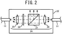
- the separation portion 24 includes a collimator lens 25, a wavelength plate 26, a beam splitter 27, and a condensing lens 28.
- the laser light separated from the optical fiber 11 is turned into a parallel light after passing the collimator lens 25.
- a phase difference (light path difference) is generated in a polarization component orthogonal to the laser light.
- the laser light is branched by the beam splitter 27 into a laser light that transmits the beam splitter 27 and a laser light reflected by the beam splitter 27.
- the laser light that transmits the beam splitter 27 is incident on the core of the optical fiber 11 again.
- a transmission rate of the laser light transmitting the beam splitter 27 is adjusted by revolving the wavelength plate 26.
- the multiplexing optical element 23 multiplexes the reference light and the measurement light reflected by the object to be measured, and causes them to interfere.
- the reference light multiplexed with the measurement light by the multiplexing optical element 23 is a laser light that transmits the optical fiber 11 and the reference light device 22A on the reference light path 13. That is, in the first embodiment, a reference optical system that generates the reference light is formed as a transmission optical system that does not return the light into the branching optical element 21 but transmits the light through the multiplexing optical element 23 so as to generate the reference light.
- the measurement light multiplexed with the reference light by the multiplexing optical element 23 is a laser light that transmits the optical fiber 11 and the projection optical system 30 on the measurement light path 12, and transmits the projection optical system 30 and the branching optical element 21 after being reflected by the object to be measured.
- the multiplexing optical element 23 of the present embodiment is formed by a fiber coupler. However, other element other than the fiber coupler may be adopted as the multiplexing optical element 23.
- the projection optical system 30 introduces the measurement light into the object to be measured, and introduces the reflection light of the measurement light reflected by the object to be measured into the optical fiber 11 of the measurement light path 12.
- the object to be measured is, for example, a fundus, an anterior ocular segment, or the like of the eye E.
- the projection optical system 30 of the present embodiment includes an optical scanner and an objective lens system.
- the measurement light is introduced to the optical scanner through the optical fiber 11.
- the optical scanner deflects a deflection direction of the measurement light.
- the measurement light deflected by the optical scanner is turned into a parallel beam by the objective lens system and is incident on the object to be measured.
- the optical scanner causes the measurement light to scan in a XY direction (crossing direction) in the object to be measured.
- Various components capable of deflecting a forward direction of the light may be adopted as the optical scanner.
- the various components capable of deflecting the forward direction of the light include a galvanometer mirror, a polygon mirror, a resonant scanner, an acoustic optical element, and the like.
- two galvanometer mirrors are adopted as the optical scanner in the present embodiment.
- the detector 40 detects the interference signal of the interference light generated by the multiplexing optical element 23.
- the light interference measurement device 1 measures the object to be measured based on the interference signal detected by the detector 40.
- the laser light introduced by the optical fiber 11 When the laser light introduced by the optical fiber 11 is temporally separated to the outside and is incident on the core again, the light is reflected in the separation portion 24 due to a difference of the refractive indexes between the core and the separation portion 24.
- the inventors of the present application found that a noise is generated in a whole waveform of the interference signal due to an influence of the reference light device 22A in a case in which the laser light for which an emission wavelength is temporally swept is used.
- the noise is assumed to be generated due to the reflection light reflected by the separation portion 24 of the reference light device 22A.
- a transmission light path length is defined by a light path length of the reference light, which transmits the reference light device 22A, from the reference light device 22A to the multiplexing optical element 23.
- a reflection light path length is defined by a light path length of the reference light, which is reflected by the separation portion 24 of the reference light device 22A, from the reference light device 22A to the multiplexing optical element 23 through the branching optical element 21.
- respective elements are arranged such that the transmission light path length is equal to or more than the reflection light path length. That is, the reference light device 22A is arranged such that the transmission light path length is equal to or more than the reflection light path length.
- the inventors of the present application found through an experiment that the noise generated in the whole waveform of the interference signal is appropriately decreased (details are described below). Consequently, according to the light interference measurement device 1 and the light interference unit 20 of the first embodiment, even in a case in which the reference light device 22A is arranged on the reference light path 13, the object to be measured can be measured further precisely based on the detected interference signal. Further, the necessity for removing the noise through a data processing after the detection is decreased, and thereby the processing time can be shortened.
- the reference light device 22A is arranged such that the transmission light path length is equal to three second or more of the reflection light path length. It is more preferable that the reference light device 22A is arranged such that the transmission light path length is equal to seven third or more of the reflection light path length. In this case, the noise generated in the whole waveform of the interference signal is further appropriately decreased.
- the number of the reference light devices 22A may be one or more. In a case in which a plurality of the reference light devices 22A is provided, it is preferable that each of the reference light devices 22A fulfills the arrangement relation described above (for example, the arrangement relation in which the transmission light path length is equal to or more than the reflection light path length). However, at least the reference light device 22A closest to the branching optical element 21 on the reference light path 13 between the branching optical element 21 and the multiplexing optical element 23 may fulfill the arrangement relation.
- the reference light device closest to the branching optical element 21 corresponds to the reference light device 22A arranged at the most upstream side on the reference light path 13.
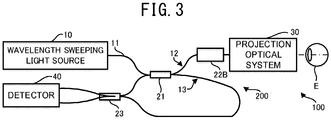
- the light interference measurement device 100 according to the second embodiment is a light coherent tomography device. As shown in Fig. 3 , the light interference measurement device 100 is provided with a wavelength sweeping light source 10, a light interference unit 200, a projection optical system 30, and a detector 40.
- the light interference unit 200 includes a branching optical element 21, at least one fiber device 22, and a multiplexing optical element 23.
- the at least one fiber device 22 includes a fiber device 22 (hereinafter, also referred to as "measurement light device 22B") arranged on a measurement light path 12 between the branching optical element 21 and an object to be measured.
- the same configuration as the fiber device 22 exemplarily shown in Fig. 2 can be adopted in the measurement light device 22B of the second embodiment, and therefore a detailed description of the measurement light device 22B is omitted.
- the light interference measurement device 100 and the light interference unit 200 may include, for example, one measurement light device 22B as the at least one fiber device 22.
- the light interference measurement device 100 and the light interference unit 200 may include the fiber device 22 on a light path other than the measurement light path 12. Further, the light interference measurement device 100 and the light interference unit 200 may include a plurality of the fiber devices 22 on the measurement light path 12.
- the multiplexing optical element 23 multiplexes the reference light and the measurement light reflected by the object to be measured, and causes them to interfere.
- the reference light multiplexed with the measurement light by the multiplexing optical element 23 is a laser light that transmits the optical fiber 11 on the reference light path 13. That is, in the second embodiment, similar to the first embodiment, the reference optical system that generates the reference light is formed as a transmission optical system.
- the measurement light multiplexed with the reference light by the multiplexing optical element 23 is a laser light that transmits the optical fiber 11, the measurement light device 22B and the projection optical system 30 on the measurement light path 12, and transmits the projection optical system 30, the measurement light device 22B and the branching optical element 21 after being reflected by the object to be measured.
- a transmission light path length is defined by a light path length of the reference light from the branching optical element 21 to the multiplexing optical element 23.
- a reflection light path length is defined by a light path length of the measurement light from the branching optical element 21 to the multiplexing optical element 23 passing the branching optical element 21 again after the measurement light is reflected by the measurement light device 22B.
- respective elements are arranged such that the transmission light path length is equal to or more than the reflection light path length. That is, the measurement light device 22B is arranged such that the transmission light path length is equal to or more than the reflection light path length.
- the noise generated in the whole waveform of the interference signal due to the measurement light device 22B is appropriately decreased. Consequently, the object to be measured can be measured further precisely based on the detected interference signal. Further, the necessity for removing the noise through a data processing after the detection is decreased, and thereby the processing time can be shortened.
- the measurement light device 22B is arranged such that the transmission light path length is equal to three second or more of the reflection light path length. It is more preferable that the measurement light device 22B is arranged such that the transmission light path length is equal to seven third or more of the reflection light path length. In this case, the noise generated in the whole waveform of the interference signal is further appropriately decreased.
- the number of the measurement light devices 22B may be one or more. In a case in which a plurality of the measurement light devices 22B is provided, it is preferable that each of the measurement light devices 22B fulfills the arrangement relation described above (for example, the arrangement relation in which the transmission light path length is equal to or more than the reflection light path length). However, at least the measurement light device 22B closest to the branching optical element 21 on the measurement light path 12 between the branching optical element 21 and the object to be measured may fulfill the arrangement relation.
- the measurement light device closest to the branching optical element 21 corresponds to the measurement light device 22B arranged at the most upstream side on the measurement light path 12.
- each of the light interference measurement device 1 and the light interference unit 100 is formed as a light coherence tomography device.
- each of the light interference measurement device 1 and the light interference unit 100 may be formed as a light interference measurement device other than the light coherence tomography device (for example, an ocular axial length measurement device that measures an ocular axial length).
- each configuration for example, a configuration of the projection optical system 30 or the like
- Various devices having a separation portion in which a laser light introduced by an optical fiber is temporally separated from a core of the optical fiber to an outside having a refractive index different from that of the core and then is incident on the core again may be adopted as the fiber device 22.
- the fiber device 22 is formed by an attenuator that adjusts the output of the laser light.
- the fiber device 22 may be formed by a device other than an attenuator.
- the fiber device 22 may be formed by an optical delay portion (optical delay line) that adjusts a light path length for the laser light. In the optical delay portion having the separation portion, a part of the laser light is reflected by the separation portion, similar to the attenuator.
- each of the reference light device 22A and the measurement light device 22B fulfills the arrangement relation in which the transmission light path length is equal to or more than the reflection light path length, an influence of a noise due to the reflection light caused by the separation portion is decreased and the light path is adjusted further precisely.
- the fiber device 22 may be formed by a circulator or an isolator. A combination of a circulator and a mirror may be used as an optical delay device. Further, the fiber device 22 may be formed by a filter type coupler having a collimator and a filter. The filter type coupler branches a laser light and multiplexes the laser lights using a characteristic of the filter. Further, the fiber device 22 may be formed by a fiber connector. Each of the circulator, the isolator, the fiber type coupler, and the fiber connector also has the separation portion.
- each of the reference light device 22A and the measurement light device 22B fulfills the arrangement relation in which the transmission light path length is equal to or more than the reflection light path length, an influence of a noise due to the reflection light caused by the separation portion is decreased and the light path is adjusted.
- the fiber device 22 may not be formed by an optical variable attenuator in which an attenuation amount of the laser light is variable as described in the embodiments described above but formed by an optical fixed attenuator in which the attenuation amount of the laser light is fixed.
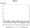
- Measurement results of a noise generated in the interference signal of an example, a first comparative example, and a second comparative example are described with reference to Fig. 4 through Fig. 6 .
- the first comparative example, and the second comparative example a light interference unit and a light interference measurement device are similar to the light interference unit 20 and the light interference measurement device 1 according to the first embodiment, however positions of the reference light devices 22A are different from each other.
- the first comparative example see Fig.
- a vertical axis of the graph denotes intensity (dB) of the noise.
- a horizontal axis of the graph denotes a point corresponding to a position in a Z direction of the object to be measured.
- the Z direction denotes an incident direction of the laser light on the object to be measured.
- the object to be measured is an eye E.
- a side having a smaller value is a retina side
- a side having a larger value is a fundus side.
- the noise is generated in the interference signal in range between 84 dB and 88 dB.
- the noise is generated in the interferences signal in a range between 84 dB and 90 dB.
- the noise is generated in the interferences signal in a range between 86 dB and 93 dB.
- the intensity of the noise generated in the interference signal is small, compared to the first comparative example and the second comparative example.
- the intensity of the noise generated in the interference signal is small, compared to the second comparative example.
- a large noise is generated in the interference signal, compared to the example and the first comparative example.
Landscapes
- Physics & Mathematics (AREA)
- General Physics & Mathematics (AREA)
- Health & Medical Sciences (AREA)
- Life Sciences & Earth Sciences (AREA)
- General Health & Medical Sciences (AREA)
- Nuclear Medicine, Radiotherapy & Molecular Imaging (AREA)
- Radiology & Medical Imaging (AREA)
- Medical Informatics (AREA)
- Public Health (AREA)
- Engineering & Computer Science (AREA)
- Biomedical Technology (AREA)
- Heart & Thoracic Surgery (AREA)
- Biophysics (AREA)
- Molecular Biology (AREA)
- Surgery (AREA)
- Animal Behavior & Ethology (AREA)
- Ophthalmology & Optometry (AREA)
- Veterinary Medicine (AREA)
- Chemical & Material Sciences (AREA)
- Analytical Chemistry (AREA)
- Biochemistry (AREA)
- Immunology (AREA)
- Pathology (AREA)
- Investigating Or Analysing Materials By Optical Means (AREA)
- Instruments For Measurement Of Length By Optical Means (AREA)
- Length Measuring Devices By Optical Means (AREA)
- Eye Examination Apparatus (AREA)
Abstract
Description
- The present disclosure relates to a light interference unit and a light interference measurement device.
- Conventionally, a light interference unit including a branching optical element, a multiplexing optical element and a fiber device has been known. The branching optical element branches light output from a light source. The multiplexing optical element multiplexes the branched lights. The fiber device includes a separation portion. In the separation portion, the light introduced by an optical fiber is temporarily separated from a core of the optical fiber to an outside having a refractive index different from that of the core and then is incident on the core again. The fiber device has at least one of functions of, for example, attenuating the light, adjusting a light path, and the like. For example, a tomographic image reading portion disclosed in
Patent Literature 1 includes a fiber coupler, which is one example of the branching optical element, a fiber coupler, which is one example of the multiplexing optical element, and a delay line unit, which is one example of the fiber device. The delay line unit adjusts a light path length of a reference light. The reference light is one light branched by the fiber coupler. Another fiber coupler multiplexes the reference light, for which the light path length is adjusted, with a measurement light. The measurement light is another light branched by the fiber coupler. The reference light and the measurement light are multiplexed, so that interference light is generated. An interference signal of the interference light is measured by a detector for each wavelength. - Patent Literature 1: Japanese Unexamined Patent Application Publication
- In the fiber device, when the light is separated from the core of the optical fiber to the outside and when the light is incident on the core again in the fiber device, the light is reflected in the separating portion. The inventors of the present application found that a noise is generated in a whole waveform of the interference signal due to an influence of the fiber device in a case in which a laser light for which an emission wavelength is temporally swept is used. The cause of the noise generated in the whole waveform has not been precisely realized, however it is assumed that the noise is generated due to a reflection light reflected by the separating portion of the fiber device.
- A typical object of the present disclosure is to provide a light interference unit and a light interference measurement device that reduce a noise generated in a whole waveform of an interference signal.
- A light interference unit provided by a typical embodiment of the present disclosure includes a branching optical element, a multiplexing optical element, and at least one fiber device. The branching optical element branches a laser light for which an emission wavelength is temporally swept, into a measurement light and a reference light. The multiplexing optical element multiplexes the reference light and the measurement light reflected by an object to be measured, and causes the reference light and the measurement light to interfere. The at least one fiber device is provided with a separating portion in which the laser light introduced by an optical fiber is temporarily separated from a core of the optical fiber to an outside having a refractive index different from that of the core and then is incident on the core again. The at least one fiber device includes a reference light device served as the fiber device arranged on a light path for the reference light between the branching optical element and the multiplexing optical element. As a transmission light path length is defined by a light path length of the reference light, which transmits the reference light device, from the reference light device to the multiplexing optical element, and a reflection light path length is defined by a light path length of the reference light, which is reflected by the separation portion of the reference light device, from the reference light device to the multiplexing optical element, the transmission light path length is equal to or more than the reflection light path length.
- A light interference measurement device provided by a typical embodiment of the present disclosure includes a wavelength sweeping light source, a branching optical element, a multiplexing optical element, at least one fiber device, and a detector. The wavelength sweeping light source emits a laser light for which an emission wavelength is temporally swept. The branching optical element branches the laser light emitted from the wavelength sweeping light source, into a measurement light and a reference light. The multiplexing optical element multiplexes the reference light and the measurement light reflected by an object to be measured, and causes the reference light and the measurement light to interfere. The at least one fiber device is provided with a separation portion in which the laser light introduced by an optical fiber is temporarily separated from a core of the optical fiber to an outside having a refractive index different from that of the core and then is incident on the core again. The detector detects an interference signal of an interference light generated by the multiplexing optical element. The at least one fiber device includes a reference light device served as the fiber device arranged on a light path for the reference light between the branching optical element and the multiplexing optical element. As a transmission light path length is defined by a light path length of the laser light, which transmits the reference light device, from the reference light device to the multiplexing optical element, and a reflection light path length is defined by a light path length of the laser light, which is reflected by the reference light device, from the reference light device to the multiplexing optical element, the transmission light path length is equal to or more than the reflection light path length.
- According to each of the light interference unit and the light interference measurement device in the present disclosure, a noise generated in a whole waveform of the interference signal is appropriately decreased.
- A first aspect of the light interference unit exemplarily described in the present disclosure includes a branching optical element, a multiplexing optical element, and at least one fiber device. The branching optical element branches a laser light for which an emission wavelength is temporally swept, into a measurement light and a reference light. The multiplexing optical element multiplexes the reference light and the measurement light reflected by an object to be measured, and causes the reference light and the measurement light to interfere. The at least one fiber device is provided with a separation portion in which the laser light introduced by an optical fiber is temporarily separated from a core of the optical fiber to an outside having a refractive index different from that of the core and then is incident on the core again. The at least one fiber device includes a reference light device served as the fiber device arranged on a light path for the reference light between the branching optical element and the multiplexing optical element. As a transmission light path length is defined by a light path length of the reference light, which transmits the reference light device, from the reference light device to the multiplexing optical element, and a reflection light path length is defined by a light path length of the reference light, which is reflected by the separation portion of the reference light device, from the reference light device to the multiplexing optical element, the transmission light path length is equal to or more than the reflection light path length. That is, the reference light device is arranged such that the transmission light path length is equal to or more than the reflection light path length. In this case, a noise generated in a whole waveform of an interference signal due to the reference light device is appropriately decreased. Consequently, the object to be measured can be measured further precisely based on the detected interference signal. Further, the necessity for removing the noise through a data processing after the detection is decreased, and thereby the processing time can be shortened.
- The number of the reference light devices may be one or more. In a case in which a plurality of the reference light devices is provided, it is preferable that each of the reference light devices fulfills an arrangement relation in which the transmission light path length is equal to or more than the reflection light path length. However, at least the reference light device closest to the branching optical element on the light path for the reference light between the branching optical element and the multiplexing optical element may fulfill the arrangement relation. The reference light device closest to the branching optical element corresponds to the reference light device arranged at the most upstream side on the light path for the reference light.
- A second aspect of the light interference unit exemplarily described in the present disclosure includes a branching optical element, a multiplexing optical element, and at least one fiber device. The branching optical element branches a laser light for which an emission wavelength is temporally swept, into a measurement light and a reference light. The multiplexing optical element multiplexes the reference light and the measurement light reflected by an object to be measured, and causes the reference light and the measurement light to interfere. The at least one fiber device includes a separation portion. In the separation portion, the laser light introduced by an optical fiber is temporarily separated from a core of the optical fiber to an outside having a refractive index different from that of the core and then is incident on the core again. The at least one fiber device includes a measurement light device. The measurement light device is served as the fiber device arranged on a light path for the measurement light between the branching optical element and the object to be measured. As a transmission light path length is defined by a light path length of the reference light from the branching optical element to the multiplexing optical element, and a reflection light path length is defined by a light path length of the measurement light from the branching optical element to the multiplexing optical element passing the branching optical element again after the measurement light is reflected by the measurement light device, the transmission light path length is equal to or more than the reflection light path length. That is, the measurement light device is arranged such that the transmission light path length is equal to or more than the reflection light path length. In this case, a noise generated in a whole waveform of an interference signal due to the measurement light device is appropriately decreased. Consequently, the object to be measured can be measured further precisely based on the detected interference signal. Further, the necessity for removing the noise through a data processing after the detection is decreased, and thereby the processing time can be shortened.
- The number of the measurement light devices may be one or more. In a case in which a plurality of the measurement light devices is provided, it is preferable that each of the measurement light devices fulfills an arrangement relation in which the transmission light path length is equal to or more than the reflection light path length. However, at least the measurement light device closest to the branching optical element on the light path for the measurement light between the branching optical element and the object to be measured may fulfill the arrangement relation. The measurement light device closest to the branching optical element corresponds to the measurement light device arranged at the most upstream side on the light path for the measurement light.
- The fiber device may be formed by an attenuator (attenuator), an optical delay portion (optical delay line), a circulator, or an isolator. The attenuator adjusts output of the laser light. The optical delay portion adjusts a light path length of the laser light. In the attenuator, the optical delay portion, the circulator, or the isolator, each of which having a separation portion, a part of the laser light is reflected by the separation portion. Against this, with a configuration that fulfills the arrangement relation in which the transmission light path length is equal to or more than the reflection light path length, an influence of a noise due to a reflection light caused by the separation portion is decreased and the light path is adjusted further precisely.
- Various devices having the separation portion may be adopted as the fiber device. In the separation portion, the laser light introduced by the optical fiber is temporarily separated from the core of the optical fiber to the outside having the refractive index different from that of the core and then is incident on the core again. Examples of the fiber device include a filter type coupler and a fiber connector.
- A first aspect of the light interference measurement device exemplarily described in the present disclosure includes a wavelength sweeping light source, a branching optical element, a multiplexing optical element, at least one fiber device, and a detector. The wavelength sweeping light source emits a laser light for which an emission wavelength is temporally swept. The branching optical element branches the laser light emitted from the wavelength sweeping light source, into a measurement light and a reference light. The multiplexing optical element multiplexes the reference light and the measurement light reflected by an object to be measured, and causes the reference light and the measurement light to interfere. The at least one fiber device includes a separation portion. The detector detects an interference signal of an interference light generated by the multiplexing optical element. In the separation portion, the laser light introduced by an optical fiber is temporarily separated from a core of the optical fiber to an outside having a refractive index different from that of the core and then is incident on the core again. The at least one fiber device includes a reference light device. The reference light device is served as the fiber device arranged on a light path for the reference light between the branching optical element and the multiplexing optical element. As a transmission light path length is defined by a light path length of the laser light, which transmits the reference light device, from the reference light device to the multiplexing optical element, and a reflection light path length is defined by a light path length of the laser light, which is reflected by the reference light device, from the reference light device to the multiplexing optical element, the transmission light path length is equal to or more than the reflection light path length. That is, the reference light device is arranged such that the transmission light path length is equal to or more than the reflection light path length. In this case, a noise generated in a whole waveform of an interference signal due to the reference light device is appropriately decreased. Consequently, the object to be measured can be measured further precisely based on the detected interference signal. Further, the necessity for removing the noise through a data processing after the detection is decreased, and thereby the processing time can be shortened.
- A second aspect of the light interference measurement device exemplarily described in the present disclosure includes a wavelength sweeping light source, a branching optical element, a multiplexing optical element, at least one fiber device, and a detector. The wavelength sweeping light source emits a laser light for which an emission wavelength is temporally swept. The branching optical element branches the laser light emitted from the wavelength sweeping light source, into a measurement light and a reference light. The multiplexing optical element multiplexes the reference light and the measurement light reflected by an object to be measured, and causes the reference light and the measurement light to interfere. The at least one fiber device includes a separation portion. In the separation portion, the laser light introduced by an optical fiber is temporarily separated from a core of the optical fiber to an outside having a refractive index different from that of the core and then is incident on the core again. The detector detects an interference signal of an interference light generated by the multiplexing optical element. The at least one fiber device includes a measurement light device. The measurement light device is served as the fiber device arranged on a light path for the measurement light between the branching optical element and the object to be measured. As a transmission light path length is defined by a light path length of the reference light from the branching optical element to the multiplexing optical element, and a reflection light path length is defined by a light path length of the measurement light from the branching optical element to the multiplexing optical element passing the branching optical element again after the measurement light is reflected by the measurement light device, the transmission light path length is equal to or more than the reflection light path length. That is, the measurement light device is arranged such that the transmission light path length is equal to or more than the reflection light path length. In this case, a noise generated in a whole waveform of an interference signal due to the measurement light device is appropriately decreased. Consequently, the object to be measured can be measured further precisely based on the detected interference signal. Further, the necessity for removing the noise through a data processing after the detection is decreased, and thereby the processing time can be shortened.
-
-
Fig. 1 is a schematic view illustrating a configuration of a lightinterference measurement device 1 according to a first embodiment. -
Fig. 2 is a schematic view illustrating a configuration of afiber device 22. -
Fig. 3 is a schematic view illustrating a configuration of a lightinterference measurement device 100 according to a second embodiment. -
Fig. 4 is a graph illustrating a measurement result of an example. -
Fig. 5 is a graph illustrating a measurement result of a first comparative example. -
Fig. 6 is a graph illustrating a measurement result of a second comparative example. - Hereinafter, exemplary embodiments of the present disclosure will be described with reference to the drawings. At first, a schematic configuration of a light
interference measurement device 1 according to a first embodiment is described with reference toFig. 1 andFig. 2 . The lightinterference measurement device 1 is a light coherence tomography device. As shown inFig. 1 , the lightinterference measurement device 1 is provided with a wavelength sweepinglight source 10, alight interference unit 20, a projectionoptical system 30, and adetector 40. - The wavelength sweeping
light source 10 emits a laser light for acquiring internal information of an object to be measured (eye E in the present embodiment), into anoptical fiber 11. The wavelength sweepinglight source 10 is formed as a wavelength scanning type light source that temporally changes an emission wavelength at a high speed. For example, the wavelength sweepinglight source 10 may include a laser medium, a resonator, and a wavelength selecting filter. The wavelength selecting filter may be formed by, for example, a combination of a diffraction grating and a polygon mirror, or a filter using a Fabry-Perot etalon. - The
light interference unit 20 includes a branchingoptical element 21, at least onefiber device 22, and a multiplexingoptical element 23. The branchingoptical element 21 branches the laser light emitted from the wavelength sweepinglight source 10 into a measurement light and a reference light and introduces them to ameasurement light path 12 and areference light path 13, respectively. As one example, the branchingoptical element 21 of the present embodiment is formed by a fiber coupler. However, other element other than the fiber coupler (for example, a circulator, a beam splitter, or the like) may be adopted as the branchingoptical element 21. - The at least one
fiber device 22 includes a fiber device 22 (hereinafter, also referred to as "reference light device 22A") arranged on thereference light path 13 between the branchingoptical element 21 and the multiplexingoptical element 23. The lightinterference measurement device 1 and thelight interference unit 20 may include, for example, one reference light device 22A as the at least onefiber device 22. The lightinterference measurement device 1 and thelight interference unit 20 may include thefiber device 22 on a light path other than thereference light path 13. Further, the lightinterference measurement device 1 and thelight interference unit 20 may include a plurality of thefiber devices 22 on thereference light path 13. - The
fiber device 22 has at least one of functions of, for example, attenuating the laser light, adjusting the light path, and the like. As one example, thefiber device 22 of the present embodiment is formed by an attenuator (attenuator) that adjusts output of the laser light. As shown inFig. 2 , thefiber device 22 includes aseparation portion 24. In theseparation portion 24, the laser light introduced by theoptical fiber 11 is temporarily separated from a core of theoptical fiber 11 to an outside having a refractive index different from that of the core and then is incident on the core again. In the example shown inFig. 2 , the outside is in the air. For example, the air has a refractive index different from that of the core. In the example shown inFig. 2 , theseparation portion 24 includes acollimator lens 25, a wavelength plate 26, abeam splitter 27, and a condensinglens 28. - In the
separation portion 24, the laser light separated from theoptical fiber 11 is turned into a parallel light after passing thecollimator lens 25. When the laser light passing thecollimator lens 25 passes the wavelength plate 26, a phase difference (light path difference) is generated in a polarization component orthogonal to the laser light. After that, the laser light is branched by thebeam splitter 27 into a laser light that transmits thebeam splitter 27 and a laser light reflected by thebeam splitter 27. The laser light that transmits thebeam splitter 27 is incident on the core of theoptical fiber 11 again. A transmission rate of the laser light transmitting thebeam splitter 27 is adjusted by revolving the wavelength plate 26. - The multiplexing
optical element 23 multiplexes the reference light and the measurement light reflected by the object to be measured, and causes them to interfere. In the first embodiment, the reference light multiplexed with the measurement light by the multiplexingoptical element 23 is a laser light that transmits theoptical fiber 11 and the reference light device 22A on thereference light path 13. That is, in the first embodiment, a reference optical system that generates the reference light is formed as a transmission optical system that does not return the light into the branchingoptical element 21 but transmits the light through the multiplexingoptical element 23 so as to generate the reference light. The measurement light multiplexed with the reference light by the multiplexingoptical element 23 is a laser light that transmits theoptical fiber 11 and the projectionoptical system 30 on themeasurement light path 12, and transmits the projectionoptical system 30 and the branchingoptical element 21 after being reflected by the object to be measured. As one example, the multiplexingoptical element 23 of the present embodiment is formed by a fiber coupler. However, other element other than the fiber coupler may be adopted as the multiplexingoptical element 23. - The projection
optical system 30 introduces the measurement light into the object to be measured, and introduces the reflection light of the measurement light reflected by the object to be measured into theoptical fiber 11 of themeasurement light path 12. The object to be measured is, for example, a fundus, an anterior ocular segment, or the like of the eye E. The projectionoptical system 30 of the present embodiment includes an optical scanner and an objective lens system. The measurement light is introduced to the optical scanner through theoptical fiber 11. The optical scanner deflects a deflection direction of the measurement light. The measurement light deflected by the optical scanner is turned into a parallel beam by the objective lens system and is incident on the object to be measured. The optical scanner causes the measurement light to scan in a XY direction (crossing direction) in the object to be measured. Various components capable of deflecting a forward direction of the light may be adopted as the optical scanner. Examples of the various components capable of deflecting the forward direction of the light include a galvanometer mirror, a polygon mirror, a resonant scanner, an acoustic optical element, and the like. As one example, two galvanometer mirrors are adopted as the optical scanner in the present embodiment. - The
detector 40 detects the interference signal of the interference light generated by the multiplexingoptical element 23. The lightinterference measurement device 1 measures the object to be measured based on the interference signal detected by thedetector 40. - When the laser light introduced by the
optical fiber 11 is temporally separated to the outside and is incident on the core again, the light is reflected in theseparation portion 24 due to a difference of the refractive indexes between the core and theseparation portion 24. The inventors of the present application found that a noise is generated in a whole waveform of the interference signal due to an influence of the reference light device 22A in a case in which the laser light for which an emission wavelength is temporally swept is used. The noise is assumed to be generated due to the reflection light reflected by theseparation portion 24 of the reference light device 22A. In the first embodiment, a transmission light path length is defined by a light path length of the reference light, which transmits the reference light device 22A, from the reference light device 22A to the multiplexingoptical element 23. A reflection light path length is defined by a light path length of the reference light, which is reflected by theseparation portion 24 of the reference light device 22A, from the reference light device 22A to the multiplexingoptical element 23 through the branchingoptical element 21. In the first embodiment, respective elements are arranged such that the transmission light path length is equal to or more than the reflection light path length. That is, the reference light device 22A is arranged such that the transmission light path length is equal to or more than the reflection light path length. In this case, the inventors of the present application found through an experiment that the noise generated in the whole waveform of the interference signal is appropriately decreased (details are described below). Consequently, according to the lightinterference measurement device 1 and thelight interference unit 20 of the first embodiment, even in a case in which the reference light device 22A is arranged on thereference light path 13, the object to be measured can be measured further precisely based on the detected interference signal. Further, the necessity for removing the noise through a data processing after the detection is decreased, and thereby the processing time can be shortened. - It is preferable that the reference light device 22A is arranged such that the transmission light path length is equal to three second or more of the reflection light path length. It is more preferable that the reference light device 22A is arranged such that the transmission light path length is equal to seven third or more of the reflection light path length. In this case, the noise generated in the whole waveform of the interference signal is further appropriately decreased.
- The number of the reference light devices 22A may be one or more. In a case in which a plurality of the reference light devices 22A is provided, it is preferable that each of the reference light devices 22A fulfills the arrangement relation described above (for example, the arrangement relation in which the transmission light path length is equal to or more than the reflection light path length). However, at least the reference light device 22A closest to the branching
optical element 21 on thereference light path 13 between the branchingoptical element 21 and the multiplexingoptical element 23 may fulfill the arrangement relation. The reference light device closest to the branchingoptical element 21 corresponds to the reference light device 22A arranged at the most upstream side on thereference light path 13. - Next, a schematic configuration of a light
interference measurement device 100 according to a second embodiment is described with reference toFig. 2 andFig. 3 . Hereinafter, the same sign is assigned to the same configuration, and the description thereof is omitted or simplified. Therefore, the configuration different from that of the first embodiment is described. The lightinterference measurement device 100 according to the second embodiment is a light coherent tomography device. As shown inFig. 3 , the lightinterference measurement device 100 is provided with a wavelength sweepinglight source 10, alight interference unit 200, a projectionoptical system 30, and adetector 40. - The
light interference unit 200 includes a branchingoptical element 21, at least onefiber device 22, and a multiplexingoptical element 23. The at least onefiber device 22 includes a fiber device 22 (hereinafter, also referred to as "measurement light device 22B") arranged on ameasurement light path 12 between the branchingoptical element 21 and an object to be measured. The same configuration as thefiber device 22 exemplarily shown inFig. 2 can be adopted in themeasurement light device 22B of the second embodiment, and therefore a detailed description of themeasurement light device 22B is omitted. The lightinterference measurement device 100 and thelight interference unit 200 may include, for example, onemeasurement light device 22B as the at least onefiber device 22. The lightinterference measurement device 100 and thelight interference unit 200 may include thefiber device 22 on a light path other than themeasurement light path 12. Further, the lightinterference measurement device 100 and thelight interference unit 200 may include a plurality of thefiber devices 22 on themeasurement light path 12. - The multiplexing
optical element 23 multiplexes the reference light and the measurement light reflected by the object to be measured, and causes them to interfere. In the second embodiment, the reference light multiplexed with the measurement light by the multiplexingoptical element 23 is a laser light that transmits theoptical fiber 11 on thereference light path 13. That is, in the second embodiment, similar to the first embodiment, the reference optical system that generates the reference light is formed as a transmission optical system. The measurement light multiplexed with the reference light by the multiplexingoptical element 23 is a laser light that transmits theoptical fiber 11, themeasurement light device 22B and the projectionoptical system 30 on themeasurement light path 12, and transmits the projectionoptical system 30, themeasurement light device 22B and the branchingoptical element 21 after being reflected by the object to be measured. - In the second embodiment, a transmission light path length is defined by a light path length of the reference light from the branching
optical element 21 to the multiplexingoptical element 23. A reflection light path length is defined by a light path length of the measurement light from the branchingoptical element 21 to the multiplexingoptical element 23 passing the branchingoptical element 21 again after the measurement light is reflected by themeasurement light device 22B. In the second embodiment, respective elements are arranged such that the transmission light path length is equal to or more than the reflection light path length. That is, themeasurement light device 22B is arranged such that the transmission light path length is equal to or more than the reflection light path length. Also in this case, the noise generated in the whole waveform of the interference signal due to themeasurement light device 22B is appropriately decreased. Consequently, the object to be measured can be measured further precisely based on the detected interference signal. Further, the necessity for removing the noise through a data processing after the detection is decreased, and thereby the processing time can be shortened. - In the second embodiment, it is preferable that the
measurement light device 22B is arranged such that the transmission light path length is equal to three second or more of the reflection light path length. It is more preferable that themeasurement light device 22B is arranged such that the transmission light path length is equal to seven third or more of the reflection light path length. In this case, the noise generated in the whole waveform of the interference signal is further appropriately decreased. - The number of the
measurement light devices 22B may be one or more. In a case in which a plurality of themeasurement light devices 22B is provided, it is preferable that each of themeasurement light devices 22B fulfills the arrangement relation described above (for example, the arrangement relation in which the transmission light path length is equal to or more than the reflection light path length). However, at least themeasurement light device 22B closest to the branchingoptical element 21 on themeasurement light path 12 between the branchingoptical element 21 and the object to be measured may fulfill the arrangement relation. The measurement light device closest to the branchingoptical element 21 corresponds to themeasurement light device 22B arranged at the most upstream side on themeasurement light path 12. - Various modifications can be applied to each of the embodiments described above. In the embodiment described above, each of the light
interference measurement device 1 and thelight interference unit 100 is formed as a light coherence tomography device. However, each of the lightinterference measurement device 1 and thelight interference unit 100 may be formed as a light interference measurement device other than the light coherence tomography device (for example, an ocular axial length measurement device that measures an ocular axial length). In this case, each configuration (for example, a configuration of the projectionoptical system 30 or the like) may be designed appropriately in accordance with a type of the device. - Various devices having a separation portion in which a laser light introduced by an optical fiber is temporally separated from a core of the optical fiber to an outside having a refractive index different from that of the core and then is incident on the core again may be adopted as the
fiber device 22. - In the examples of the embodiments described above, the
fiber device 22 is formed by an attenuator that adjusts the output of the laser light. However, thefiber device 22 may be formed by a device other than an attenuator. For example, thefiber device 22 may be formed by an optical delay portion (optical delay line) that adjusts a light path length for the laser light. In the optical delay portion having the separation portion, a part of the laser light is reflected by the separation portion, similar to the attenuator. Against this, with a configuration in which each of the reference light device 22A and themeasurement light device 22B fulfills the arrangement relation in which the transmission light path length is equal to or more than the reflection light path length, an influence of a noise due to the reflection light caused by the separation portion is decreased and the light path is adjusted further precisely. - The
fiber device 22 may be formed by a circulator or an isolator. A combination of a circulator and a mirror may be used as an optical delay device. Further, thefiber device 22 may be formed by a filter type coupler having a collimator and a filter. The filter type coupler branches a laser light and multiplexes the laser lights using a characteristic of the filter. Further, thefiber device 22 may be formed by a fiber connector. Each of the circulator, the isolator, the fiber type coupler, and the fiber connector also has the separation portion. With a configuration in which each of the reference light device 22A and themeasurement light device 22B fulfills the arrangement relation in which the transmission light path length is equal to or more than the reflection light path length, an influence of a noise due to the reflection light caused by the separation portion is decreased and the light path is adjusted. - The
fiber device 22 may not be formed by an optical variable attenuator in which an attenuation amount of the laser light is variable as described in the embodiments described above but formed by an optical fixed attenuator in which the attenuation amount of the laser light is fixed. - Measurement results of a noise generated in the interference signal of an example, a first comparative example, and a second comparative example are described with reference to
Fig. 4 through Fig. 6 . In the example, the first comparative example, and the second comparative example, a light interference unit and a light interference measurement device are similar to thelight interference unit 20 and the lightinterference measurement device 1 according to the first embodiment, however positions of the reference light devices 22A are different from each other. In the example (seeFig. 4 ), "transmission light path length : reflection light path length = 1.3 : 1" is fulfilled. That is, in the example, the reference light device 22A is arranged such that the transmission light path length is more than the reflection light path length. In the first comparative example (seeFig. 5 ), "transmission light path length : reflection light path length = 1 : 1" is fulfilled. That is, in the first comparative example, the reference light device 22A is arranged such that the transmission light path length is substantially equal to the reflection light path length. Accordingly, in each of the example and the first comparative example, the reference light device 22A fulfills the arrangement relation described in the first embodiment. While, in the second comparative example (seeFig. 6 ), "transmission light path length : reflection light path length = 0.6 : 1" is fulfilled. That is, in the second comparative example, the reference light device 22A is arranged such that the transmission light path length is less than the reflection light path length. Accordingly, in the second comparative example, the reference light device 22A does not fulfill the arrangement relation described in the first embodiment. - In each of
Fig. 4 through Fig. 6 , a vertical axis of the graph denotes intensity (dB) of the noise. A horizontal axis of the graph denotes a point corresponding to a position in a Z direction of the object to be measured. The Z direction denotes an incident direction of the laser light on the object to be measured. In the experiment, the object to be measured is an eye E. In the horizontal axis, a side having a smaller value is a retina side, and a side having a larger value is a fundus side. As shown inFig. 4 , in the example, the noise is generated in the interference signal in range between 84 dB and 88 dB. As shown inFig. 5 , in the first comparative example, the noise is generated in the interferences signal in a range between 84 dB and 90 dB. As shown inFig. 6 , in the second comparative example, the noise is generated in the interferences signal in a range between 86 dB and 93 dB. - In the example, the intensity of the noise generated in the interference signal is small, compared to the first comparative example and the second comparative example. In the first comparative example, the intensity of the noise generated in the interference signal is small, compared to the second comparative example. In the second comparative example, a large noise is generated in the interference signal, compared to the example and the first comparative example. Based on the measurement result of the present experiment, it is found that, in a case in which the reference light device 22A is arranged such that the transmission light path length is equal to or more than the reflection light path length, the noise generated in the whole waveform of the interference signal is appropriately decreased. Further, it is found that the noise is decreased in a case in which the transmission light path length is more than the reflection light path length more than a case in which the transmission light path length is substantially equal to the reflection light path length.
Claims (3)
- A light interference unit comprising:a branching optical element that branches a laser light for which an emission wavelength is temporally swept, into a measurement light and a reference light;a multiplexing optical element that multiplexes the reference light and the measurement light reflected by an object to be measured, and causes the reference light and the measurement light to interfere; andat least one fiber device provided with a separation portion in which the laser light introduced by an optical fiber is temporarily separated from a core of the optical fiber to an outside having a refractive index different from that of the core and then is incident on the core again,characterized in that:the at least one fiber device includes a reference light device served as the fiber device arranged on a light path for the reference light between the branching optical element and the multiplexing optical element; andas a transmission light path length is defined by a light path length of the reference light, which transmits the reference light device, from the reference light device to the multiplexing optical element, and a reflection light path length is defined by a light path length of the reference light, which is reflected by the separation portion of the reference light device, from the reference light device to the multiplexing optical element, the transmission light path length is equal to or more than the reflection light path length.
- The light interference unit according to claim 1, wherein the fiber device is formed by an attenuator that adjusts output of the laser light, an optical delay portion that adjusts a light path length of the laser light, a circulator, or an isolator.
- A light interference measurement device comprising:a wavelength sweeping light source that emits a laser light for which an emission wavelength is temporally swept;a branching optical element that branches the laser light emitted from the wavelength sweeping light source, into a measurement light and a reference light;a multiplexing optical element that multiplexes the reference light and the measurement light reflected by an object to be measured, and causes the reference light and the measurement light to interfere;at least one fiber device provided with a separation portion in which the laser light introduced by an optical fiber is temporarily separated from a core of the optical fiber to an outside having a refractive index different from that of the core and then is incident on the core again; anda detector that detects an interference signal of an interference light generated by the multiplexing optical element,characterized in that:the at least one fiber device includes a reference light device served as the fiber device arranged on a light path for the reference light between the branching optical element and the multiplexing optical element; andas a transmission light path length is defined by a light path length of the laser light, which transmits the reference light device, from the reference light device to the multiplexing optical element, and a reflection light path length is defined by a light path length of the laser light, which is reflected by the reference light device, from the reference light device to the multiplexing optical element, the transmission light path length is equal to or more than the reflection light path length.
Applications Claiming Priority (2)
| Application Number | Priority Date | Filing Date | Title |
|---|---|---|---|
| JP2017112500A JP6826496B2 (en) | 2017-06-07 | 2017-06-07 | Optical interference unit and optical interference measuring device |
| PCT/JP2018/020464 WO2018225574A1 (en) | 2017-06-07 | 2018-05-29 | Light interference unit and light interference measurement device |
Publications (3)
| Publication Number | Publication Date |
|---|---|
| EP3637041A1 true EP3637041A1 (en) | 2020-04-15 |
| EP3637041A4 EP3637041A4 (en) | 2021-03-10 |
| EP3637041B1 EP3637041B1 (en) | 2023-09-20 |
Family
ID=64567079
Family Applications (1)
| Application Number | Title | Priority Date | Filing Date |
|---|---|---|---|
| EP18813050.4A Active EP3637041B1 (en) | 2017-06-07 | 2018-05-29 | Light interference unit and light interference measurement device |
Country Status (5)
| Country | Link |
|---|---|
| US (1) | US11054240B2 (en) |
| EP (1) | EP3637041B1 (en) |
| JP (1) | JP6826496B2 (en) |
| CN (1) | CN110720022B (en) |
| WO (1) | WO2018225574A1 (en) |
Families Citing this family (5)
| Publication number | Priority date | Publication date | Assignee | Title |
|---|---|---|---|---|
| JP2019150381A (en) * | 2018-03-05 | 2019-09-12 | 株式会社トーメーコーポレーション | Interferometer |
| JP6647700B2 (en) * | 2019-08-23 | 2020-02-14 | 株式会社トーメーコーポレーション | Interferometer |
| JP7363614B2 (en) | 2020-03-13 | 2023-10-18 | オムロン株式会社 | Optical interference measurement device |
| JP7691657B2 (en) | 2021-09-15 | 2025-06-12 | オムロン株式会社 | Optical Interferometric Distance Sensor |
| CN121499496A (en) * | 2022-11-02 | 2026-02-10 | 库力索法高科股份有限公司 | All-fiber 3D tomography system |
Family Cites Families (22)
| Publication number | Priority date | Publication date | Assignee | Title |
|---|---|---|---|---|
| JP3400503B2 (en) * | 1993-10-26 | 2003-04-28 | 松下電工株式会社 | Interferometer |
| JP4464519B2 (en) * | 2000-03-21 | 2010-05-19 | オリンパス株式会社 | Optical imaging device |
| JP3739987B2 (en) * | 2000-02-18 | 2006-01-25 | 財団法人神奈川科学技術アカデミー | Tomography equipment |
| KR20040016406A (en) * | 2002-08-15 | 2004-02-21 | 호야 가부시키가이샤 | Optical module |
| US20080013955A1 (en) * | 2004-05-26 | 2008-01-17 | Hoya Corporation | Optical Module and Optical Wavelength Multiplexing and Demultiplexing Device |
| JP4583986B2 (en) * | 2005-03-22 | 2010-11-17 | 株式会社フジクラ | Chromatic dispersion measurement device |
| ES2669059T3 (en) * | 2005-07-28 | 2018-05-23 | Bioptigen, Inc. | Optical coherence tomography imaging system in the frequency domain |
| JP5192395B2 (en) * | 2006-01-19 | 2013-05-08 | オプトビュー,インコーポレーテッド | Fourier domain optical coherence tomography |
| WO2007133961A2 (en) * | 2006-05-10 | 2007-11-22 | The General Hospital Corporation | Processes, arrangements and systems for providing frequency domain imaging of a sample |
| JP2008128926A (en) * | 2006-11-24 | 2008-06-05 | Fujifilm Corp | Optical tomographic imaging system |
| JP5513101B2 (en) * | 2009-12-25 | 2014-06-04 | 株式会社トプコン | Optical image measuring device |
| DE102011011277B4 (en) * | 2011-02-11 | 2024-05-08 | Carl Zeiss Meditec Ag | Optimized device for swept source optical coherence domain reflectometry and tomography |
| CN104411233B (en) | 2012-02-03 | 2017-08-29 | 俄勒冈健康科学大学 | In vivo optical flow imaging |
| JP5772783B2 (en) * | 2012-10-17 | 2015-09-02 | 住友電気工業株式会社 | Optical tomographic image acquisition device |
| JP6227337B2 (en) * | 2013-01-24 | 2017-11-08 | 株式会社日立エルジーデータストレージ | Optical measuring device |
| JP2014226173A (en) | 2013-05-20 | 2014-12-08 | 株式会社トーメーコーポレーション | Optical tomographic image generating device, method for controlling the optical tomographic image generating device, program therefor, and storage medium |
| JP6465557B2 (en) * | 2014-04-08 | 2019-02-06 | 株式会社トーメーコーポレーション | Tomography equipment |
| JP6310792B2 (en) * | 2014-06-30 | 2018-04-11 | 株式会社トプコン | Skin property evaluation device |
| US10327631B2 (en) * | 2015-01-16 | 2019-06-25 | Oregon Health & Science University | Post-processing reduction of fixed pattern artifacts and trigger jitter in swept-source optical coherence tomography |
| CA2988987A1 (en) * | 2015-06-19 | 2016-12-22 | Visunex Medical Systems Co. Ltd. | A wide field of view optical coherence tomography imaging system |
| JP6758900B2 (en) * | 2016-04-28 | 2020-09-23 | キヤノン株式会社 | Ophthalmic imaging device |
| CN107495921B (en) * | 2017-09-29 | 2019-02-19 | 视微影像(河南)科技有限公司 | An optical coherence tomography imaging system |
-
2017
- 2017-06-07 JP JP2017112500A patent/JP6826496B2/en active Active
-
2018
- 2018-05-29 EP EP18813050.4A patent/EP3637041B1/en active Active
- 2018-05-29 WO PCT/JP2018/020464 patent/WO2018225574A1/en not_active Ceased
- 2018-05-29 CN CN201880037887.8A patent/CN110720022B/en active Active
-
2019
- 2019-12-09 US US16/706,995 patent/US11054240B2/en active Active
Also Published As
| Publication number | Publication date |
|---|---|
| US11054240B2 (en) | 2021-07-06 |
| EP3637041B1 (en) | 2023-09-20 |
| US20200116471A1 (en) | 2020-04-16 |
| JP2018205203A (en) | 2018-12-27 |
| CN110720022A (en) | 2020-01-21 |
| WO2018225574A1 (en) | 2018-12-13 |
| JP6826496B2 (en) | 2021-02-03 |
| CN110720022B (en) | 2022-03-29 |
| EP3637041A4 (en) | 2021-03-10 |
Similar Documents
| Publication | Publication Date | Title |
|---|---|---|
| US11054240B2 (en) | Light interference unit and light interference measurement device | |
| US20210316756A1 (en) | Device and method for scanning measurement of the distance to an object | |
| JP5086104B2 (en) | Laser radar system and system and method for providing chirped electromagnetic waves | |
| KR100871097B1 (en) | Optical Imaging System Based on Coherent Frequency Domain Reflectometry | |
| WO2010074321A1 (en) | Optical tomographic imaging apparatus | |
| US10520594B2 (en) | Method and fibre-optical system for illuminating and detecting an object by means of light | |
| US10349829B2 (en) | Ophthalmic imaging apparatus | |
| CN112154301B (en) | OCT system and OCT method | |
| CN107228635A (en) | Optical measuring device | |
| CN107567305B (en) | camera equipment | |
| CN107450179A (en) | Active correlation imaging optical system based on multi-channel semiconductor laser | |
| EP3150108B1 (en) | Removable oct device | |
| JP6632262B2 (en) | Ophthalmic apparatus and operating method thereof | |
| US9052179B2 (en) | Optical coherence tomography apparatus and method | |
| WO2016002693A1 (en) | Tomography device | |
| JP2019080868A (en) | Ophthalmic imaging apparatus | |
| JP2017102013A (en) | Scanning type microscope | |
| CN120342494B (en) | Signal transceiver and bidirectional beaconing-free laser communication device | |
| CN111060890A (en) | Lidar equipment | |
| JP7006874B2 (en) | OCT system and OCT method | |
| JP2023071068A (en) | Optical interferometer | |
| KR102067628B1 (en) | A distance determining apparatus and method thereof | |
| US9482511B2 (en) | System and method for interlacing differing coherence length sweeps to improve OCT image quality | |
| JP6723835B2 (en) | Optical coherence tomography device | |
| WO2019172166A1 (en) | Scanning device and distance measuring device |
Legal Events
| Date | Code | Title | Description |
|---|---|---|---|
| STAA | Information on the status of an ep patent application or granted ep patent |
Free format text: STATUS: THE INTERNATIONAL PUBLICATION HAS BEEN MADE |
|
| PUAI | Public reference made under article 153(3) epc to a published international application that has entered the european phase |
Free format text: ORIGINAL CODE: 0009012 |
|
| STAA | Information on the status of an ep patent application or granted ep patent |
Free format text: STATUS: REQUEST FOR EXAMINATION WAS MADE |
|
| 17P | Request for examination filed |
Effective date: 20191206 |
|
| AK | Designated contracting states |
Kind code of ref document: A1 Designated state(s): AL AT BE BG CH CY CZ DE DK EE ES FI FR GB GR HR HU IE IS IT LI LT LU LV MC MK MT NL NO PL PT RO RS SE SI SK SM TR |
|
| AX | Request for extension of the european patent |
Extension state: BA ME |
|
| DAV | Request for validation of the european patent (deleted) | ||
| DAX | Request for extension of the european patent (deleted) | ||
| A4 | Supplementary search report drawn up and despatched |
Effective date: 20210210 |
|
| RIC1 | Information provided on ipc code assigned before grant |
Ipc: G01N 21/17 20060101ALI20210204BHEP Ipc: G01B 11/24 20060101ALI20210204BHEP Ipc: G01B 9/02 20060101AFI20210204BHEP Ipc: A61B 3/10 20060101ALI20210204BHEP |
|
| GRAP | Despatch of communication of intention to grant a patent |
Free format text: ORIGINAL CODE: EPIDOSNIGR1 |
|
| STAA | Information on the status of an ep patent application or granted ep patent |
Free format text: STATUS: GRANT OF PATENT IS INTENDED |
|
| INTG | Intention to grant announced |
Effective date: 20230417 |
|
| P01 | Opt-out of the competence of the unified patent court (upc) registered |
Effective date: 20230712 |
|
| GRAS | Grant fee paid |
Free format text: ORIGINAL CODE: EPIDOSNIGR3 |
|
| GRAA | (expected) grant |
Free format text: ORIGINAL CODE: 0009210 |
|
| STAA | Information on the status of an ep patent application or granted ep patent |
Free format text: STATUS: THE PATENT HAS BEEN GRANTED |
|
| AK | Designated contracting states |
Kind code of ref document: B1 Designated state(s): AL AT BE BG CH CY CZ DE DK EE ES FI FR GB GR HR HU IE IS IT LI LT LU LV MC MK MT NL NO PL PT RO RS SE SI SK SM TR |
|
| REG | Reference to a national code |
Ref country code: GB Ref legal event code: FG4D |
|
| REG | Reference to a national code |
Ref country code: CH Ref legal event code: EP |
|
| REG | Reference to a national code |
Ref country code: DE Ref legal event code: R096 Ref document number: 602018057985 Country of ref document: DE |
|
| REG | Reference to a national code |
Ref country code: IE Ref legal event code: FG4D |
|
| REG | Reference to a national code |
Ref country code: LT Ref legal event code: MG9D |
|
| PG25 | Lapsed in a contracting state [announced via postgrant information from national office to epo] |
Ref country code: GR Free format text: LAPSE BECAUSE OF FAILURE TO SUBMIT A TRANSLATION OF THE DESCRIPTION OR TO PAY THE FEE WITHIN THE PRESCRIBED TIME-LIMIT Effective date: 20231221 |
|
| REG | Reference to a national code |
Ref country code: NL Ref legal event code: MP Effective date: 20230920 |
|
| PG25 | Lapsed in a contracting state [announced via postgrant information from national office to epo] |
Ref country code: SE Free format text: LAPSE BECAUSE OF FAILURE TO SUBMIT A TRANSLATION OF THE DESCRIPTION OR TO PAY THE FEE WITHIN THE PRESCRIBED TIME-LIMIT Effective date: 20230920 Ref country code: RS Free format text: LAPSE BECAUSE OF FAILURE TO SUBMIT A TRANSLATION OF THE DESCRIPTION OR TO PAY THE FEE WITHIN THE PRESCRIBED TIME-LIMIT Effective date: 20230920 Ref country code: NO Free format text: LAPSE BECAUSE OF FAILURE TO SUBMIT A TRANSLATION OF THE DESCRIPTION OR TO PAY THE FEE WITHIN THE PRESCRIBED TIME-LIMIT Effective date: 20231220 Ref country code: LV Free format text: LAPSE BECAUSE OF FAILURE TO SUBMIT A TRANSLATION OF THE DESCRIPTION OR TO PAY THE FEE WITHIN THE PRESCRIBED TIME-LIMIT Effective date: 20230920 Ref country code: LT Free format text: LAPSE BECAUSE OF FAILURE TO SUBMIT A TRANSLATION OF THE DESCRIPTION OR TO PAY THE FEE WITHIN THE PRESCRIBED TIME-LIMIT Effective date: 20230920 Ref country code: HR Free format text: LAPSE BECAUSE OF FAILURE TO SUBMIT A TRANSLATION OF THE DESCRIPTION OR TO PAY THE FEE WITHIN THE PRESCRIBED TIME-LIMIT Effective date: 20230920 Ref country code: GR Free format text: LAPSE BECAUSE OF FAILURE TO SUBMIT A TRANSLATION OF THE DESCRIPTION OR TO PAY THE FEE WITHIN THE PRESCRIBED TIME-LIMIT Effective date: 20231221 Ref country code: FI Free format text: LAPSE BECAUSE OF FAILURE TO SUBMIT A TRANSLATION OF THE DESCRIPTION OR TO PAY THE FEE WITHIN THE PRESCRIBED TIME-LIMIT Effective date: 20230920 |
|
| REG | Reference to a national code |
Ref country code: AT Ref legal event code: MK05 Ref document number: 1613696 Country of ref document: AT Kind code of ref document: T Effective date: 20230920 |
|
| PG25 | Lapsed in a contracting state [announced via postgrant information from national office to epo] |
Ref country code: NL Free format text: LAPSE BECAUSE OF FAILURE TO SUBMIT A TRANSLATION OF THE DESCRIPTION OR TO PAY THE FEE WITHIN THE PRESCRIBED TIME-LIMIT Effective date: 20230920 |
|
| PG25 | Lapsed in a contracting state [announced via postgrant information from national office to epo] |
Ref country code: IS Free format text: LAPSE BECAUSE OF FAILURE TO SUBMIT A TRANSLATION OF THE DESCRIPTION OR TO PAY THE FEE WITHIN THE PRESCRIBED TIME-LIMIT Effective date: 20240120 |
|
| PG25 | Lapsed in a contracting state [announced via postgrant information from national office to epo] |
Ref country code: AT Free format text: LAPSE BECAUSE OF FAILURE TO SUBMIT A TRANSLATION OF THE DESCRIPTION OR TO PAY THE FEE WITHIN THE PRESCRIBED TIME-LIMIT Effective date: 20230920 |
|
| PG25 | Lapsed in a contracting state [announced via postgrant information from national office to epo] |
Ref country code: ES Free format text: LAPSE BECAUSE OF FAILURE TO SUBMIT A TRANSLATION OF THE DESCRIPTION OR TO PAY THE FEE WITHIN THE PRESCRIBED TIME-LIMIT Effective date: 20230920 |
|
| PG25 | Lapsed in a contracting state [announced via postgrant information from national office to epo] |
Ref country code: SM Free format text: LAPSE BECAUSE OF FAILURE TO SUBMIT A TRANSLATION OF THE DESCRIPTION OR TO PAY THE FEE WITHIN THE PRESCRIBED TIME-LIMIT Effective date: 20230920 Ref country code: RO Free format text: LAPSE BECAUSE OF FAILURE TO SUBMIT A TRANSLATION OF THE DESCRIPTION OR TO PAY THE FEE WITHIN THE PRESCRIBED TIME-LIMIT Effective date: 20230920 Ref country code: IS Free format text: LAPSE BECAUSE OF FAILURE TO SUBMIT A TRANSLATION OF THE DESCRIPTION OR TO PAY THE FEE WITHIN THE PRESCRIBED TIME-LIMIT Effective date: 20240120 Ref country code: ES Free format text: LAPSE BECAUSE OF FAILURE TO SUBMIT A TRANSLATION OF THE DESCRIPTION OR TO PAY THE FEE WITHIN THE PRESCRIBED TIME-LIMIT Effective date: 20230920 Ref country code: EE Free format text: LAPSE BECAUSE OF FAILURE TO SUBMIT A TRANSLATION OF THE DESCRIPTION OR TO PAY THE FEE WITHIN THE PRESCRIBED TIME-LIMIT Effective date: 20230920 Ref country code: CZ Free format text: LAPSE BECAUSE OF FAILURE TO SUBMIT A TRANSLATION OF THE DESCRIPTION OR TO PAY THE FEE WITHIN THE PRESCRIBED TIME-LIMIT Effective date: 20230920 Ref country code: AT Free format text: LAPSE BECAUSE OF FAILURE TO SUBMIT A TRANSLATION OF THE DESCRIPTION OR TO PAY THE FEE WITHIN THE PRESCRIBED TIME-LIMIT Effective date: 20230920 Ref country code: SK Free format text: LAPSE BECAUSE OF FAILURE TO SUBMIT A TRANSLATION OF THE DESCRIPTION OR TO PAY THE FEE WITHIN THE PRESCRIBED TIME-LIMIT Effective date: 20230920 Ref country code: PT Free format text: LAPSE BECAUSE OF FAILURE TO SUBMIT A TRANSLATION OF THE DESCRIPTION OR TO PAY THE FEE WITHIN THE PRESCRIBED TIME-LIMIT Effective date: 20240122 |
|
| PG25 | Lapsed in a contracting state [announced via postgrant information from national office to epo] |
Ref country code: PL Free format text: LAPSE BECAUSE OF FAILURE TO SUBMIT A TRANSLATION OF THE DESCRIPTION OR TO PAY THE FEE WITHIN THE PRESCRIBED TIME-LIMIT Effective date: 20230920 Ref country code: IT Free format text: LAPSE BECAUSE OF FAILURE TO SUBMIT A TRANSLATION OF THE DESCRIPTION OR TO PAY THE FEE WITHIN THE PRESCRIBED TIME-LIMIT Effective date: 20230920 |
|
| REG | Reference to a national code |
Ref country code: DE Ref legal event code: R097 Ref document number: 602018057985 Country of ref document: DE |
|
| PG25 | Lapsed in a contracting state [announced via postgrant information from national office to epo] |
Ref country code: DK Free format text: LAPSE BECAUSE OF FAILURE TO SUBMIT A TRANSLATION OF THE DESCRIPTION OR TO PAY THE FEE WITHIN THE PRESCRIBED TIME-LIMIT Effective date: 20230920 |
|
| PLBE | No opposition filed within time limit |
Free format text: ORIGINAL CODE: 0009261 |
|
| STAA | Information on the status of an ep patent application or granted ep patent |
Free format text: STATUS: NO OPPOSITION FILED WITHIN TIME LIMIT |
|
| PG25 | Lapsed in a contracting state [announced via postgrant information from national office to epo] |
Ref country code: DK Free format text: LAPSE BECAUSE OF FAILURE TO SUBMIT A TRANSLATION OF THE DESCRIPTION OR TO PAY THE FEE WITHIN THE PRESCRIBED TIME-LIMIT Effective date: 20230920 |
|
| 26N | No opposition filed |
Effective date: 20240621 |
|
| PG25 | Lapsed in a contracting state [announced via postgrant information from national office to epo] |
Ref country code: SI Free format text: LAPSE BECAUSE OF FAILURE TO SUBMIT A TRANSLATION OF THE DESCRIPTION OR TO PAY THE FEE WITHIN THE PRESCRIBED TIME-LIMIT Effective date: 20230920 |
|
| PG25 | Lapsed in a contracting state [announced via postgrant information from national office to epo] |
Ref country code: SI Free format text: LAPSE BECAUSE OF FAILURE TO SUBMIT A TRANSLATION OF THE DESCRIPTION OR TO PAY THE FEE WITHIN THE PRESCRIBED TIME-LIMIT Effective date: 20230920 |
|
| PG25 | Lapsed in a contracting state [announced via postgrant information from national office to epo] |
Ref country code: BG Free format text: LAPSE BECAUSE OF FAILURE TO SUBMIT A TRANSLATION OF THE DESCRIPTION OR TO PAY THE FEE WITHIN THE PRESCRIBED TIME-LIMIT Effective date: 20230920 |
|
| PG25 | Lapsed in a contracting state [announced via postgrant information from national office to epo] |
Ref country code: BG Free format text: LAPSE BECAUSE OF FAILURE TO SUBMIT A TRANSLATION OF THE DESCRIPTION OR TO PAY THE FEE WITHIN THE PRESCRIBED TIME-LIMIT Effective date: 20230920 |
|
| REG | Reference to a national code |
Ref country code: CH Ref legal event code: PL |
|
| PG25 | Lapsed in a contracting state [announced via postgrant information from national office to epo] |
Ref country code: MC Free format text: LAPSE BECAUSE OF FAILURE TO SUBMIT A TRANSLATION OF THE DESCRIPTION OR TO PAY THE FEE WITHIN THE PRESCRIBED TIME-LIMIT Effective date: 20230920 |
|
| PG25 | Lapsed in a contracting state [announced via postgrant information from national office to epo] |
Ref country code: LU Free format text: LAPSE BECAUSE OF NON-PAYMENT OF DUE FEES Effective date: 20240529 |
|
| PG25 | Lapsed in a contracting state [announced via postgrant information from national office to epo] |
Ref country code: MC Free format text: LAPSE BECAUSE OF FAILURE TO SUBMIT A TRANSLATION OF THE DESCRIPTION OR TO PAY THE FEE WITHIN THE PRESCRIBED TIME-LIMIT Effective date: 20230920 Ref country code: LU Free format text: LAPSE BECAUSE OF NON-PAYMENT OF DUE FEES Effective date: 20240529 Ref country code: CH Free format text: LAPSE BECAUSE OF NON-PAYMENT OF DUE FEES Effective date: 20240531 |
|
| REG | Reference to a national code |
Ref country code: BE Ref legal event code: MM Effective date: 20240531 |
|
| PG25 | Lapsed in a contracting state [announced via postgrant information from national office to epo] |
Ref country code: IE Free format text: LAPSE BECAUSE OF NON-PAYMENT OF DUE FEES Effective date: 20240529 |
|
| PG25 | Lapsed in a contracting state [announced via postgrant information from national office to epo] |
Ref country code: BE Free format text: LAPSE BECAUSE OF NON-PAYMENT OF DUE FEES Effective date: 20240531 |
|
| PG25 | Lapsed in a contracting state [announced via postgrant information from national office to epo] |
Ref country code: FR Free format text: LAPSE BECAUSE OF NON-PAYMENT OF DUE FEES Effective date: 20240531 |
|
| PGFP | Annual fee paid to national office [announced via postgrant information from national office to epo] |
Ref country code: DE Payment date: 20250402 Year of fee payment: 8 |
|
| PGFP | Annual fee paid to national office [announced via postgrant information from national office to epo] |
Ref country code: GB Payment date: 20250401 Year of fee payment: 8 |
|
| PG25 | Lapsed in a contracting state [announced via postgrant information from national office to epo] |
Ref country code: CY Free format text: LAPSE BECAUSE OF FAILURE TO SUBMIT A TRANSLATION OF THE DESCRIPTION OR TO PAY THE FEE WITHIN THE PRESCRIBED TIME-LIMIT; INVALID AB INITIO Effective date: 20180529 |
|
| PG25 | Lapsed in a contracting state [announced via postgrant information from national office to epo] |
Ref country code: HU Free format text: LAPSE BECAUSE OF FAILURE TO SUBMIT A TRANSLATION OF THE DESCRIPTION OR TO PAY THE FEE WITHIN THE PRESCRIBED TIME-LIMIT; INVALID AB INITIO Effective date: 20180529 |