EP3636492A1 - Motor vehicle assembly comprising a lighting fabric - Google Patents
Motor vehicle assembly comprising a lighting fabric Download PDFInfo
- Publication number
- EP3636492A1 EP3636492A1 EP19201699.6A EP19201699A EP3636492A1 EP 3636492 A1 EP3636492 A1 EP 3636492A1 EP 19201699 A EP19201699 A EP 19201699A EP 3636492 A1 EP3636492 A1 EP 3636492A1
- Authority
- EP
- European Patent Office
- Prior art keywords
- illuminating
- fabric
- lighting
- assembly
- support
- Prior art date
- Legal status (The legal status is an assumption and is not a legal conclusion. Google has not performed a legal analysis and makes no representation as to the accuracy of the status listed.)
- Granted
Links
- 239000004744 fabric Substances 0.000 title claims abstract description 116
- 239000003086 colorant Substances 0.000 claims description 5
- 239000000835 fiber Substances 0.000 claims description 3
- 238000007789 sealing Methods 0.000 claims description 3
- 238000005034 decoration Methods 0.000 claims 2
- 238000000034 method Methods 0.000 description 24
- 210000001519 tissue Anatomy 0.000 description 22
- 238000012423 maintenance Methods 0.000 description 3
- 239000013307 optical fiber Substances 0.000 description 3
- 238000004026 adhesive bonding Methods 0.000 description 2
- 238000001816 cooling Methods 0.000 description 2
- 230000002093 peripheral effect Effects 0.000 description 2
- 239000012209 synthetic fiber Substances 0.000 description 2
- 229920002994 synthetic fiber Polymers 0.000 description 2
Images

Classifications
-
- F—MECHANICAL ENGINEERING; LIGHTING; HEATING; WEAPONS; BLASTING
- F21—LIGHTING
- F21S—NON-PORTABLE LIGHTING DEVICES; SYSTEMS THEREOF; VEHICLE LIGHTING DEVICES SPECIALLY ADAPTED FOR VEHICLE EXTERIORS
- F21S43/00—Signalling devices specially adapted for vehicle exteriors, e.g. brake lamps, direction indicator lights or reversing lights
- F21S43/10—Signalling devices specially adapted for vehicle exteriors, e.g. brake lamps, direction indicator lights or reversing lights characterised by the light source
- F21S43/13—Signalling devices specially adapted for vehicle exteriors, e.g. brake lamps, direction indicator lights or reversing lights characterised by the light source characterised by the type of light source
- F21S43/14—Light emitting diodes [LED]
-
- B—PERFORMING OPERATIONS; TRANSPORTING
- B60—VEHICLES IN GENERAL
- B60Q—ARRANGEMENT OF SIGNALLING OR LIGHTING DEVICES, THE MOUNTING OR SUPPORTING THEREOF OR CIRCUITS THEREFOR, FOR VEHICLES IN GENERAL
- B60Q1/00—Arrangement of optical signalling or lighting devices, the mounting or supporting thereof or circuits therefor
- B60Q1/26—Arrangement of optical signalling or lighting devices, the mounting or supporting thereof or circuits therefor the devices being primarily intended to indicate the vehicle, or parts thereof, or to give signals, to other traffic
- B60Q1/2615—Arrangement of optical signalling or lighting devices, the mounting or supporting thereof or circuits therefor the devices being primarily intended to indicate the vehicle, or parts thereof, or to give signals, to other traffic mounted on the vehicle body, e.g. with magnets
-
- B—PERFORMING OPERATIONS; TRANSPORTING
- B60—VEHICLES IN GENERAL
- B60Q—ARRANGEMENT OF SIGNALLING OR LIGHTING DEVICES, THE MOUNTING OR SUPPORTING THEREOF OR CIRCUITS THEREFOR, FOR VEHICLES IN GENERAL
- B60Q1/00—Arrangement of optical signalling or lighting devices, the mounting or supporting thereof or circuits therefor
- B60Q1/0029—Spatial arrangement
- B60Q1/0041—Spatial arrangement of several lamps in relation to each other
- B60Q1/0058—Stacked, i.e. one lamp located behind the other in the optical axis direction
-
- F—MECHANICAL ENGINEERING; LIGHTING; HEATING; WEAPONS; BLASTING
- F21—LIGHTING
- F21S—NON-PORTABLE LIGHTING DEVICES; SYSTEMS THEREOF; VEHICLE LIGHTING DEVICES SPECIALLY ADAPTED FOR VEHICLE EXTERIORS
- F21S43/00—Signalling devices specially adapted for vehicle exteriors, e.g. brake lamps, direction indicator lights or reversing lights
- F21S43/10—Signalling devices specially adapted for vehicle exteriors, e.g. brake lamps, direction indicator lights or reversing lights characterised by the light source
- F21S43/13—Signalling devices specially adapted for vehicle exteriors, e.g. brake lamps, direction indicator lights or reversing lights characterised by the light source characterised by the type of light source
- F21S43/14—Light emitting diodes [LED]
- F21S43/145—Surface emitters, e.g. organic light emitting diodes [OLED]
-
- F—MECHANICAL ENGINEERING; LIGHTING; HEATING; WEAPONS; BLASTING
- F21—LIGHTING
- F21S—NON-PORTABLE LIGHTING DEVICES; SYSTEMS THEREOF; VEHICLE LIGHTING DEVICES SPECIALLY ADAPTED FOR VEHICLE EXTERIORS
- F21S43/00—Signalling devices specially adapted for vehicle exteriors, e.g. brake lamps, direction indicator lights or reversing lights
- F21S43/10—Signalling devices specially adapted for vehicle exteriors, e.g. brake lamps, direction indicator lights or reversing lights characterised by the light source
- F21S43/19—Attachment of light sources or lamp holders
-
- F—MECHANICAL ENGINEERING; LIGHTING; HEATING; WEAPONS; BLASTING
- F21—LIGHTING
- F21S—NON-PORTABLE LIGHTING DEVICES; SYSTEMS THEREOF; VEHICLE LIGHTING DEVICES SPECIALLY ADAPTED FOR VEHICLE EXTERIORS
- F21S45/00—Arrangements within vehicle lighting devices specially adapted for vehicle exteriors, for purposes other than emission or distribution of light
- F21S45/10—Protection of lighting devices
-
- F—MECHANICAL ENGINEERING; LIGHTING; HEATING; WEAPONS; BLASTING
- F21—LIGHTING
- F21V—FUNCTIONAL FEATURES OR DETAILS OF LIGHTING DEVICES OR SYSTEMS THEREOF; STRUCTURAL COMBINATIONS OF LIGHTING DEVICES WITH OTHER ARTICLES, NOT OTHERWISE PROVIDED FOR
- F21V19/00—Fastening of light sources or lamp holders
- F21V19/001—Fastening of light sources or lamp holders the light sources being semiconductors devices, e.g. LEDs
-
- B—PERFORMING OPERATIONS; TRANSPORTING
- B60—VEHICLES IN GENERAL
- B60Q—ARRANGEMENT OF SIGNALLING OR LIGHTING DEVICES, THE MOUNTING OR SUPPORTING THEREOF OR CIRCUITS THEREFOR, FOR VEHICLES IN GENERAL
- B60Q2400/00—Special features or arrangements of exterior signal lamps for vehicles
- B60Q2400/10—Electro- or photo- luminescent surfaces, e.g. signalling by way of electroluminescent strips or panels
-
- F—MECHANICAL ENGINEERING; LIGHTING; HEATING; WEAPONS; BLASTING
- F21—LIGHTING
- F21W—INDEXING SCHEME ASSOCIATED WITH SUBCLASSES F21K, F21L, F21S and F21V, RELATING TO USES OR APPLICATIONS OF LIGHTING DEVICES OR SYSTEMS
- F21W2107/00—Use or application of lighting devices on or in particular types of vehicles
- F21W2107/10—Use or application of lighting devices on or in particular types of vehicles for land vehicles
Definitions
- the invention relates to the field of the automobile industry, and in particular motor vehicle parts comprising an lighting device, in particular the external parts.
- illuminating part which comprises an illuminating fabric.
- Such parts are described for example in the application FR3046389 .
- a drawback of the use of these illuminating fabrics lies in the fact that they necessarily comprise a non-illuminating technical zone, generally on their periphery, the function of which is to allow the illuminating parts of the fabric to be connected to a light source.
- the presence of this technical zone generally implies that a peripheral part of the external part does not have an illuminating zone, which is annoying because it is desirable to be able to illuminate the external part up to its edge. Or, if it is desired that the illuminating zone be flush with the edge of the part, the technical zone presents an annoying bulk and can disturb the connections with other parts.
- the object of the invention is in particular to provide a motor vehicle assembly provided with an illuminating fabric making it possible to illuminate the vehicle in a less restrictive manner for the aesthetics of the vehicle.
- the second illuminating part is placed on the first technical zone, it is possible to illuminate “dead zones”, which are not lit because they are technical. Therefore, the surface of the assembly can be fully illuminating, and more particularly the periphery of the first illuminating part.
- the term "illuminating fabric” generally means a set of natural and / or synthetic fibers comprising optical fibers inserted through meshes of the fabric or woven with natural or synthetic fibers.
- Other types of illuminating fabrics can also be used, for example light can be emitted by light-emitting diodes (LEDs) inserted in a fabric.
- LEDs light-emitting diodes
- the technical area for joining an illuminating part to a light source is located on the periphery of the illuminating part, on at least one of the edges of the illuminating fabric.
- the technical area can be non-illuminating or illuminating. In the latter case, however, its brightness is not satisfactory for ensuring the lighting function provided by the illuminating part.
- this shape of the support allows the external surface of the assembly to appear as substantially flat, and without roughness.
- the decorative element thus advantageously makes it possible to hide the technical areas of the two second illuminating fabrics.
- FIG. 1 a motor vehicle assembly, designated by the general reference 1, according to an embodiment of the invention.
- the set 1 represented on the figure 1 is a set of motor vehicle.
- the motor vehicle assembly 1 comprises a support 10 intended to receive a first lighting fabric 12 and a second lighting fabric 14.
- the first lighting fabric 12 comprises an lighting part 122, called “first lighting part” and a technical area 124 called “first technical area ”.
- the second lighting fabric 14 includes an lighting part 142, called “second lighting part” and a technical area 144 called “second technical area”.
- the technical zones 124 and 144 can be non-illuminating or even illuminating. In the case where the technical zones are illuminating, their brightness is, in any case, not satisfactory to ensure a satisfactory lighting function.
- the first and second lighting fabrics 12, 14 are arranged so that the second lighting part 142 covers the first technical area 124.
- the face of the assembly 1 on which the lighting fabrics 12, 14 are placed can appear as illuminated over substantially its entire surface when the first and second illuminating fabrics 12, 14 are supplied by a light source.
- the assembly 1 is an external assembly, configured to be visible from outside the vehicle, for example the assembly 1 is a part of an external part of the vehicle, or is attached to a part external of a vehicle.
- an illuminating fabric for the exterior of the vehicle, it will be noted that the illuminating fabric is very flexible compared to a conventional lighting device, so that it can easily conform to shapes. , notably curves, of the very varied external part. Furthermore, an illuminating fabric is compact and can be easy to personalize by varying the colors of the light and / or of the patterns arranged above the fabric. Thus, a particularly interesting application is to easily offer the user a personalized light signature of his vehicle.
- the support 10 intended to receive the illuminating fabrics 12, 14 comprises a substantially planar surface 102 for receiving the first illuminating part 122, and also comprises a cavity 104 for receiving the first technical area 124 delimited by a wall set back from to the reception surface 102 of the first illuminating part 122.
- the first technical area 124 can be housed inside the cavity 104, and is therefore set back from the reception surface 102.
- the lighting part 122 of the first lighting fabric 12 can be fixed to the flat part of the receiving support 102 by any suitable means, for example by gluing, or by mechanical means allowing the lighting fabric 12 to be hung on the support 10.
- the lighting part 142 of the second lighting fabric 14 (also called the second lighting part) is attached to the cavity 104 so as to cover this cavity.
- the technical area 124 of the first lighting fabric 12 is thus covered by the lighting part 142 of the second lighting fabric 14.
- the second lighting part 142 is also preferably arranged substantially in the same plane as the first lighting part 122.
- the face exterior of the assembly 1 appears to be substantially planar.
- the support 10 may include a receiving cavity 106 of the second technical zone 144.
- the cavity is delimited by a wall recessed with respect to the receiving surface 102 of the first lighting part 122.
- the second technical zone 144 can be housed inside the cavity 106, and therefore it is set back from the receiving surface 102. This also contributes to the fact that the external face of the assembly 1 appears to be substantially planar.
- the cavities 104 and 106 are configured so as to accommodate the respective technical zones 124 and 144 while respecting a sufficiently low curvature so as not to damage the illuminating fibers.
- the illuminating fabrics 12, 14 comprise optical fibers, which are not able to be bent by a radius that is too small without risk of damage.
- the first lighting part 122 comprises a plurality of panels of lighting fabrics 126 emitting light of different colors from each other, and the substantially planar receiving surface 102 of the first lighting part 122 comprises protruding grooves 110 facing the edges of each panel 126 so as to ensure the luminous sealing of the edges of the various panels 126 of the first lighting part 122.
- each of the receiving cavities 104 and 106 comprises in its recessed wall at least one through opening 108 intended to receive an element for connecting the lighting fabric 12, 14 to a light source.
- the connection of the luminous fabrics 12, 14 to a light source is quick and easy.
- several openings 108 are formed in the wall of the receiving cavity 104, 106. Most often, but this is not limiting, a light source is provided for each opening 108.
- the cavity 104 makes it possible to reserve a space for receiving the technical elements of the illuminating fabric, separated from the light source. As a result, it is possible to better protect the technical elements and the lighting fabric, which are fragile and difficult to repair, while placing the light source outside the cavity 104, which is particularly advantageous for increasing its duration. life.
- the light source is an LED module, it is preferable that it is not confined in a closed housing since this impacts the cooling performance of the LED, and therefore its lifespan.
- the light source is placed in an area accessible, which facilitates its maintenance. The light source can also be moved to limit the damage due to an impact, and facilitate the change of the damaged area.
- the second lighting fabric 14 is received on a support 16.
- the support 16 is generally a panel or a plate of small thickness, and whose other dimensions are substantially similar to those of the second lighting part 142.
- the support 16 is arranged on the receiving cavity 104 of the first technical area, and closes the cavity.
- the support panel 16 of the second lighting part 142 covers the first technical area 124.
- the panel 16 is opaque.
- the support panel 16 gives better mechanical strength to the second lighting fabric 14, and can also allow easier and faster mounting of the second lighting fabric 14 on the support 10.
- the second lighting fabric 14 is fixed to the support 16 by any means suitable, such as gluing or mechanical fixing.
- the assembly 1 can comprise two second illuminating fabrics 14, optionally each received by a support 16.
- the two illuminating fabrics 14 can be separated by a decorative element 20.
- the technical zones 144 of each of the two second fabrics 14 are positioned between the two fabrics 14, and the decorative element 20 thus covers the technical area 144 of each of the two second lighting fabrics 14, which makes it possible to hide the technical areas 144 of the two second lighting fabrics 14.
- each of the second technical zones 144 may be separate or confused. In the case where they are combined, the same cavity 106 can advantageously accommodate the technical zones 144 of the two second illuminating fabrics 14.
- the assembly 1 comprises a plurality of n partially superimposed illuminating fabrics, preferably not being greater than 3.
- Each of the n illuminating fabrics comprises an illuminating part and a technical area for joining the illuminating part to a light source.
- the illuminating part of the illuminating fabric n is disposed on the support 10 so as to cover the technical area of the illuminating fabric n-1.
- the assembly 1 further comprises an element 18 at least partially transparent or translucent, attached to the lighting fabric (s) on their face opposite to the support 10.
- This element 18 is intended to cover the lighting fabric 12, 14 for the protect. In some cases, only part of element 18 is transparent or translucent, so as to make a luminous pattern appear when the illuminating fabrics are supplied with light.
- the element 18 is located on the external face of the external assembly when the latter is installed on the vehicle.
- the assembly 1 can be attached to a bumper skin of a vehicle. It can also be installed on other parts of the vehicle on which a uniform lighting function is desired, or on which it is desired to create a light pattern.
Abstract
Ensemble de véhicule automobile (1) comprenant un tissu éclairant (12, 14) et un support de tissu éclairant (10), et comprenant :- un premier tissu éclairant (12) comprenant une première partie éclairante (122) et une première zone technique (124) de jonction de la première partie éclairante (122) à une source lumineuse,- un second tissu éclairant (14) comprenant une seconde partie éclairante (142) et une seconde zone technique (144) de jonction de la seconde partie éclairante (142) à une source lumineuse,- un support du premier tissu éclairant (10) et du second tissu éclairant, la seconde partie éclairante (142) étant disposée sur le support (10) de façon à recouvrir la première zone technique (124).Motor vehicle assembly (1) comprising an illuminating fabric (12, 14) and an illuminating fabric support (10), and comprising: - a first illuminating fabric (12) comprising a first illuminating part (122) and a first technical area (124) for joining the first lighting part (122) to a light source, - a second lighting fabric (14) comprising a second lighting part (142) and a second technical area (144) for joining the second lighting part ( 142) to a light source, a support for the first lighting fabric (10) and the second lighting fabric, the second lighting part (142) being arranged on the support (10) so as to cover the first technical area (124).
Description
L'invention concerne le domaine de l'industrie automobile, et notamment les pièces de véhicule automobile comportant un dispositif éclairant, en particulier les pièces externes.The invention relates to the field of the automobile industry, and in particular motor vehicle parts comprising an lighting device, in particular the external parts.
On connaît déjà des pièces externes de véhicule automobile pourvues d'une partie éclairante qui comprend un tissu éclairant. De telles pièces sont décrites par exemple dans la demande
L'invention a notamment pour but de fournir un ensemble de véhicule automobile muni d'un tissu éclairant permettant d'éclairer le véhicule de façon moins contraignante pour l'esthétique du véhicule.The object of the invention is in particular to provide a motor vehicle assembly provided with an illuminating fabric making it possible to illuminate the vehicle in a less restrictive manner for the aesthetics of the vehicle.
A cet effet l'invention a pour objet un ensemble de véhicule automobile comprenant un tissu éclairant et un support de tissu éclairant, et comprenant plus particulièrement :
- un premier tissu éclairant comprenant une première partie éclairante et une première zone technique de jonction de la première partie éclairante à une source lumineuse,
- un second tissu éclairant comprenant une seconde partie éclairante et une seconde zone technique de jonction de la seconde partie éclairante à une source lumineuse,
- un support du premier tissu éclairant et du second tissu éclairant, la seconde partie éclairante étant disposée sur le support de façon à recouvrir la première zone technique.
- a first lighting fabric comprising a first lighting part and a first technical zone for joining the first lighting part to a light source,
- a second illuminating fabric comprising a second illuminating part and a second technical zone for joining the second illuminating part to a light source,
- a support for the first lighting fabric and the second lighting fabric, the second lighting part being arranged on the support so as to cover the first technical area.
Ainsi, grâce au fait que la seconde partie éclairante est placée sur la première zone technique, on peut éclairer des « zones mortes », non éclairées car techniques. De ce fait, la surface de l'ensemble peut être entièrement éclairante, et plus particulièrement la périphérie de la première partie éclairante.Thus, thanks to the fact that the second illuminating part is placed on the first technical zone, it is possible to illuminate “dead zones”, which are not lit because they are technical. Therefore, the surface of the assembly can be fully illuminating, and more particularly the periphery of the first illuminating part.
Dans la présente description, on entend généralement par « tissu éclairant » un ensemble de fibres naturelles et/ou synthétiques comprenant des fibres optiques insérées à travers des mailles du tissu ou tissées avec les fibres naturelles ou synthétiques. D'autres types de tissus éclairants peuvent également être utilisés, par exemple la lumière peut être émise par des diodes électroluminescentes (LEDs) insérées dans un tissu.In the present description, the term "illuminating fabric" generally means a set of natural and / or synthetic fibers comprising optical fibers inserted through meshes of the fabric or woven with natural or synthetic fibers. Other types of illuminating fabrics can also be used, for example light can be emitted by light-emitting diodes (LEDs) inserted in a fabric.
Généralement, dans les tissus éclairants employés dans le cadre de l'invention, la zone technique de jonction d'une partie éclairante à une source lumineuse est située en périphérie de la partie éclairante, sur au moins un des bords du tissu éclairant. On comprend que la zone technique peut être non éclairante ou bien éclairante. Dans ce dernier cas, sa luminosité n'est en revanche pas satisfaisante pour assurer la fonction d'éclairage assurée par la partie éclairante.Generally, in the illuminating fabrics used in the context of the invention, the technical area for joining an illuminating part to a light source is located on the periphery of the illuminating part, on at least one of the edges of the illuminating fabric. We understand that the technical area can be non-illuminating or illuminating. In the latter case, however, its brightness is not satisfactory for ensuring the lighting function provided by the illuminating part.
Suivant d'autres caractéristiques optionnelles de l'ensemble de véhicule automobile, prises seules ou en combinaison :
- Le support est configuré pour être visible depuis l'extérieur du véhicule. Il est particulièrement intéressant de pouvoir éclairer l'extérieur du véhicule au moyen d'un tissu éclairant, et le fait de pouvoir éclairer les bords périphériques des pièces extérieures est avantageux car on sait que le design extérieur d'un véhicule, tout en alliant les contraintes d'assemblages des pièces, est une préoccupation des constructeurs automobiles. Parmi les avantages de l'utilisation d'un tissu éclairant pour l'extérieur du véhicule, on notera que le tissu éclairant est très souple par rapport à un dispositif d'éclairage classique, de sorte qu'en cas de choc il peut s'avérer être peu endommagé malgré sa relative fragilité, tout en pouvant se conformer facilement à des formes, notamment des galbes, de la pièce extérieure très variées. Par ailleurs, un tissu éclairant est peu encombrant et peut être facile à personnaliser en variant les couleurs de la lumière et/ou des motifs disposés au dessus du tissu. Ainsi, une application particulièrement intéressante est de proposer facilement à l'utilisateur une signature lumineuse personnalisée de son véhicule.
- Le support comprend une surface sensiblement plane de réception de la première partie éclairante, et une cavité de réception de la première zone technique, délimitée par une paroi en retrait par rapport à la surface de réception de la première partie éclairante, la seconde partie éclairante étant rapportée sur la cavité de réception de la première zone technique de façon à recouvrir la cavité de réception de la première zone technique.
- The support is configured to be visible from outside the vehicle. It is particularly advantageous to be able to illuminate the exterior of the vehicle by means of an illuminating fabric, and the fact of being able to illuminate the peripheral edges of the exterior parts is advantageous because it is known that the exterior design of a vehicle, while combining the constraints of assembling parts, is a concern of car manufacturers. Among the advantages of using an illuminating fabric for the exterior of the vehicle, it will be noted that the illuminating fabric is very flexible compared to a conventional lighting device, so that in the event of an impact it may prove to be little damaged despite its relative fragility, while being able to easily conform to shapes, in particular curves, of the very varied external part. Furthermore, an illuminating fabric is compact and can be easy to personalize by varying the colors of the light and / or of the patterns arranged above the fabric. Thus, a particularly interesting application is to easily offer the user a personalized light signature of his vehicle.
- The support comprises a substantially flat surface for receiving the first illuminating part, and a receiving cavity for the first technical zone, delimited by a wall set back from the receiving surface of the first illuminating part, the second illuminating part being attached to the receiving cavity of the first technical area so as to cover the receiving cavity of the first technical area.
Ainsi, on propose un renfoncement permettant de loger la première zone technique, cette forme du support permettant que la surface extérieure de l'ensemble apparaisse comme sensiblement plane, et sans aspérité.
- La première partie éclairante comprend au moins deux panneaux de tissus éclairants émettant chacun de la lumière de couleurs différentes, et le support du premier tissu éclairant comprend des nervures saillantes en regard des bords de chaque panneau pour assurer l'étanchéité lumineuse des bords des panneaux de la première partie éclairante.
- The first illuminating part comprises at least two panels of illuminating fabric each emitting light of different colors, and the support of the first illuminating fabric comprises protruding ribs facing the edges of each panel to ensure the light sealing of the edges of the panels of the first illuminating part.
On peut ainsi disposer des panneaux de tissus éclairants adjacents de couleur différente sans interférence de lumière sur les bords.
- Le support comprend une cavité de réception de la seconde zone technique, délimitée par une paroi en retrait par rapport à la surface de réception de la première partie éclairante.
- The support comprises a receiving cavity of the second technical zone, delimited by a wall recessed with respect to the receiving surface of the first lighting part.
Ainsi, de la même façon que pour la première zone technique, cette forme du support permet que la surface extérieure de l'ensemble apparaisse comme sensiblement plane, et sans aspérité.Thus, in the same way as for the first technical area, this shape of the support allows the external surface of the assembly to appear as substantially flat, and without roughness.
On notera que les cavités de réception de la première zone technique et de la seconde zone technique peuvent être des cavités distinctes ou bien confondues.
- La cavité de réception de la première zone technique ou de la seconde zone technique est configurée de manière à accueillir la zone technique correspondante en respectant une courbure du tissu éclairant correspondant suffisamment faible pour ne pas endommager les fibres éclairantes.
- The receiving cavity of the first technical zone or of the second technical zone is configured so as to receive the corresponding technical zone while respecting a curvature of the corresponding illuminating fabric sufficiently small so as not to damage the illuminating fibers.
Cette caractéristique est particulièrement utile dans le cas où le tissu éclairant comprend des fibres optiques.
- La paroi en retrait de la cavité de réception de la première zone technique ou de la seconde zone technique comprend au moins une ouverture traversante, destinée à recevoir un élément de raccordement du tissu éclairant à une source lumineuse. Un avantage réside dans le fait que la cavité permet de réserver un espace pour recevoir les éléments techniques du tissu éclairant, séparé de la source lumineuse. Il en résulte que l'on peut mieux protéger les éléments techniques et le tissu éclairants, qui sont fragiles et difficilement réparables, tout en disposant la source lumineuse à l'extérieur du logement, ce qui est particulièrement intéressant pour augmenter sa durée de vie. En effet, dans le cas où la source lumineuse est un module de LED, il est préférable qu'il ne soit pas confiné dans un logement fermé car cela impacte les performances de refroidissement de la LED, et donc sa durée de vie. En outre grâce à la configuration proposée, on dispose la source lumineuse dans une zone accessible, ce qui facilite sa maintenance. La source lumineuse peut également être déportée pour limiter les dégâts dus à un choc, et faciliter le changement de la zone endommagée.
- L'ensemble comprend un panneau de support de la seconde partie éclairante, recouvrant la première zone technique, le panneau de support étant de préférence opaque. Ainsi, on fait en sorte que la partie technique du premier tissu éclairant ne perturbe pas l'éclairage de la seconde partie éclairante.
- L'ensemble comprend deux seconds tissus éclairants séparés par un élément de décoration, cet élément de décoration recouvrant la seconde zone technique de chacun des deux seconds tissus éclairants.
- The wall set back from the receiving cavity of the first technical zone or of the second technical zone comprises at least one through opening, intended to receive an element for connecting the illuminating fabric to a light source. An advantage lies in the fact that the cavity makes it possible to reserve a space to receive the technical elements of the illuminating fabric, separated from the light source. As a result, it is possible to better protect the technical elements and the lighting fabric, which are fragile and difficult to repair, while placing the light source outside the housing, which is particularly advantageous for increasing its service life. Indeed, in the case where the light source is an LED module, it is preferable that it is not confined in a closed housing because this impacts the cooling performance of the LED, and therefore its lifespan. In addition, thanks to the proposed configuration, the light source is placed in an accessible area, which facilitates its maintenance. The light source can also be moved to limit the damage due to an impact, and facilitate the change of the damaged area.
- The assembly comprises a support panel for the second illuminating part, covering the first technical area, the support panel preferably being opaque. Thus, we make sure that the technical part of the first lighting fabric does not disturb the lighting of the second lighting part.
- The assembly includes two second illuminating fabrics separated by a decorative element, this decorative element covering the second technical area of each of the two second illuminating fabrics.
L'élément de décoration permet ainsi avantageusement de cacher les zones techniques des deux seconds tissus éclairants. De manière alternative, on peut prévoir un seul second tissu éclairant et un élément de décoration recouvrant la seconde zone technique.The decorative element thus advantageously makes it possible to hide the technical areas of the two second illuminating fabrics. Alternatively, it is possible to provide a single second illuminating fabric and a decorative element covering the second technical area.
On notera d'autre part que les cavités de réception de chacune des secondes zones techniques peuvent être distinctes ou confondues. Dans le cas où elles sont confondues, une même cavité peut avantageusement accueillir les zones techniques des deux seconds tissus.
- L'ensemble comprend une pluralité de n tissus éclairants partiellement superposés, comprenant chacun une partie éclairante et une zone technique de jonction de la partie éclairante à une source lumineuse, la partie éclairante du tissu éclairant n étant disposée sur le support de façon à recouvrir la zone technique du tissu éclairant n-1. Dans ce cas, le nombre n est de préférence supérieur ou égal à 3.
- L'ensemble comprend un élément au moins partiellement transparent ou translucide destiné à recouvrir les tissus éclairants pour les protéger et éventuellement faire apparaître un motif lumineux.
- L'ensemble est configuré pour être rapporté sur une peau de pare-chocs.
- The assembly comprises a plurality of n partially superimposed illuminating fabrics, each comprising an illuminating part and a technical area for joining the illuminating part to a light source, the illuminating part of the illuminating fabric n being disposed on the support so as to cover the technical area of the illuminating fabric n-1. In this case, the number n is preferably greater than or equal to 3.
- The assembly includes an element at least partially transparent or translucent intended to cover the illuminating fabrics to protect them and possibly reveal a light pattern.
- The assembly is configured to be attached to a bumper skin.
L'invention sera mieux comprise à la lecture de la description qui va suivre donnée uniquement à titre d'exemple et faite en se référant aux dessins annexés dans lesquels :
- la [
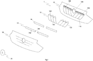
Fig. 1 ] est une vue en perspective éclatée schématique d'un ensemble externe de véhicule automobile selon un mode de réalisation de l'invention. - la [
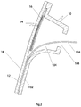
Fig. 2 ] est une section latérale partielle schématique de l'ensemble externe de lafigure 1 . - la [
Fig. 3 ] est une vue avant en perspective schématique de l'ensemble externe de lafigure 1 monté sur une pièce extérieure de véhicule.
- the [
Fig. 1 ] is a schematic exploded perspective view of an external assembly of a motor vehicle according to an embodiment of the invention. - the [
Fig. 2 ] is a schematic partial side section of the external assembly of thefigure 1 . - the [
Fig. 3 ] is a schematic perspective front view of the external assembly of thefigure 1 mounted on an exterior vehicle part.
On a représenté sur la
L'ensemble de véhicule automobile 1 comprend un support 10 destiné à recevoir un premier tissu éclairant 12 et un second tissu éclairant 14. Le premier tissu éclairant 12 comporte une partie éclairante 122, dite « première partie éclairante » et une zone technique 124 dite «première zone technique ». Le second tissu éclairant 14 comporte une partie éclairante 142, dite « seconde partie éclairante » et une zone technique 144 dite « seconde zone technique ».The
Les zones techniques 124 et 144 peuvent être non éclairantes ou bien éclairantes. Dans le cas où les zones techniques sont éclairantes, leur luminosité n'est, quoi qu'il en soit, pas satisfaisante pour assurer une fonction d'éclairage satisfaisante.The
Dans la suite de la description on notera que :
- « première partie éclairante 122 » est synonyme de « partie éclairante 122 du premier tissu éclairant 12 »
- «
première zone technique 124 » est synonyme de «zone technique 124 du premier tissu éclairant 12 ». Cette zone technique est une zone de jonction du tissu éclairant à une source lumineuse, - « seconde partie éclairante 142 » est synonyme de « partie éclairante 142 du second tissu éclairant 14 »
- «
seconde zone technique 144 » est synonyme de «zone technique 144 du second tissu éclairant 14 ».
- "
First lighting part 122" is synonymous with "lighting part 122 of thefirst lighting fabric 12" - "First
technical area 124" is synonymous with "technical area 124 of thefirst light fabric 12". This technical area is a junction area of the illuminating fabric with a light source, - "
Second lighting part 142" is synonymous with "lighting part 142 of thesecond lighting fabric 14" - "Second
technical zone 144" is synonymous with "technical zone 144 of thesecond lighting fabric 14".
Les premier et second tissus éclairants 12, 14 sont disposés de manière à ce que la seconde partie éclairante 142 recouvre la première zone technique 124. Ainsi la face de l'ensemble 1 sur laquelle sont placés les tissus éclairants 12, 14 peut apparaître comme éclairée sur sensiblement toute sa surface lorsque les premier et second tissus éclairants 12, 14 sont alimentés par une source lumineuse.The first and
Dans un mode de réalisation préféré, l'ensemble 1 est un ensemble externe, configuré pour être visible depuis l'extérieur du véhicule, par exemple l'ensemble 1 est une partie d'une pièce externe de véhicule, ou est rapporté sur une pièce externe d'un véhicule.In a preferred embodiment, the
Il est particulièrement intéressant de pouvoir éclairer une pièce extérieure du véhicule au moyen d'un tissu éclairant, et le fait de pouvoir éclairer la périphérie des pièces extérieures est avantageux car on sait que le design extérieur d'un véhicule est une préoccupation des constructeurs automobiles, tout en nécessitant de prendre en compte les contraintes d'assemblages des pièces. Parmi les avantages de l'utilisation d'un tissu éclairant pour l'extérieur du véhicule, on notera que le tissu éclairant est très souple par rapport à un dispositif d'éclairage classique, de sorte qu'il peut se conformer facilement à des formes, notamment des galbes, de la pièce extérieure très variées. Par ailleurs, un tissu éclairant est peu encombrant et peut être facile à personnaliser en variant les couleurs de la lumière et/ou des motifs disposés au-dessus du tissu. Ainsi, une application particulièrement intéressante est de proposer facilement à l'utilisateur une signature lumineuse personnalisée de son véhicule.It is particularly advantageous to be able to illuminate an exterior part of the vehicle by means of an illuminating fabric, and the fact of being able to illuminate the periphery of the exterior parts is advantageous since it is known that the exterior design of a vehicle is a concern of automobile manufacturers. , while requiring to take into account the constraints of assembling the parts. Among the advantages of using an illuminating fabric for the exterior of the vehicle, it will be noted that the illuminating fabric is very flexible compared to a conventional lighting device, so that it can easily conform to shapes. , notably curves, of the very varied external part. Furthermore, an illuminating fabric is compact and can be easy to personalize by varying the colors of the light and / or of the patterns arranged above the fabric. Thus, a particularly interesting application is to easily offer the user a personalized light signature of his vehicle.
Dans un mode de réalisation, représenté par les
La partie éclairante 122 de premier tissu éclairant 12 peut être fixée à la partie plane du support de réception 102 par tout moyen approprié, par exemple par collage, ou par un moyen mécanique permettant d'accrocher le tissu éclairant 12 sur le support 10.The
La partie éclairante 142 du second tissu éclairant 14 (aussi appelée seconde partie éclairante) est rapportée sur la cavité 104 de manière à recouvrir cette cavité. La zone technique 124 du premier tissu éclairant 12 est ainsi recouverte par la partie éclairante 142 du second tissu éclairant 14.The
La seconde partie éclairante 142 est en outre de préférence disposée sensiblement dans le même plan que la première partie éclairante 122. Ainsi, la face extérieure de l'ensemble 1 apparaît comme étant sensiblement plane.The
Le support 10 peut comprendre une cavité de réception 106 de la seconde zone technique 144. La cavité est délimitée par une paroi en retrait par rapport à la surface de réception 102 de la première partie éclairante 122. De cette manière, la seconde zone technique 144 peut être logée à l'intérieur de la cavité 106, et par conséquent elle se trouve en retrait de la surface de réception 102. Cela contribue également à ce que la face extérieure de l'ensemble 1 apparaisse comme étant sensiblement plane.The
De préférence, les cavités 104 et 106 sont configurées de manière à accueillir les zones techniques respectives 124 et 144 en respectant une courbure suffisamment faible pour ne pas endommager les fibres éclairantes. En particulier, dans un mode de réalisation, les tissus éclairants 12, 14 comprennent des fibres optiques, qui ne sont pas aptes à être courbées selon un rayon trop faible sans risque d'endommagement.Preferably, the
Dans un mode de réalisation, représenté par la
De préférence, chacune des cavités de réception 104 et 106 comprend dans sa paroi en retrait au moins une ouverture traversante 108 destinée à recevoir un élément de raccordement du tissu éclairant 12, 14 à une source lumineuse. Ainsi le raccordement des tissus lumineux 12, 14 à une source lumineuse est rapide et aisé. Avantageusement, plusieurs ouvertures 108 sont ménagées dans la paroi de la cavité de réception 104, 106. Le plus souvent, mais cela n'est pas limitatif, une source lumineuse est prévue pour chaque ouverture 108.Preferably, each of the receiving
Un autre avantage réside dans le fait que la cavité 104 permet de réserver un espace pour recevoir les éléments techniques du tissu éclairant, séparé de la source lumineuse. Il en résulte que l'on peut mieux protéger les éléments techniques et le tissu éclairants, qui sont fragiles et difficilement réparables, tout en disposant la source lumineuse à l'extérieur de la cavité 104, ce qui est particulièrement intéressant pour augmenter sa durée de vie. En effet, dans le cas où la source lumineuse est un module de LED, il est préférable qu'il ne soit pas confiné dans un logement fermé car cela impacte les performances de refroidissement de la LED, et donc sa durée de vie. En outre grâce à la configuration proposée, on dispose la source lumineuse dans une zone accessible, ce qui facilite sa maintenance. La source lumineuse peut également être déportée pour limiter les dégâts dus à un choc, et faciliter le changement de la zone endommagée.Another advantage lies in the fact that the
Dans un mode de réalisation préférentiel, le second tissu éclairant 14 est reçu sur un support 16. Le support 16 est généralement un panneau ou une plaque de faible épaisseur, et dont les autres dimensions sont sensiblement similaires à celles de la seconde partie éclairante 142. Le support 16 est agencé sur la cavité de réception 104 de la première zone technique, et ferme la cavité. Ainsi, le panneau de support 16 de la seconde partie éclairante 142 recouvre la première zone technique 124. De préférence, le panneau 16 est opaque. Le panneau de support 16 donne une meilleure tenue mécanique au second tissu éclairant 14, et peut également permettre un montage plus facile et plus rapide du second tissu éclairant 14 sur le support 10. Le second tissu éclairant 14 est fixé au support 16 par tout moyen approprié, tel qu'un collage ou une fixation mécanique.In a preferred embodiment, the
Dans un mode de réalisation, et ainsi que cela est représenté sur la
On notera d'autre part que les cavités de réception 106 de chacune des secondes zones techniques 144 peuvent être distinctes ou confondues. Dans le cas où elles sont confondues, une même cavité 106 peut avantageusement accueillir les zones techniques 144 des deux seconds tissus éclairants 14.It will also be noted that the receiving
Dans un mode de réalisation particulier, l'ensemble 1 comprend une pluralité de n tissus éclairants partiellement superposés, n'étant de préférence supérieur à 3. Chacun des n tissus éclairants comprend une partie éclairante et une zone technique de jonction de la partie éclairante à une source lumineuse. La partie éclairante du tissu éclairant n est disposée sur le support 10 de façon à recouvrir la zone technique du tissu éclairant n-1.In a particular embodiment, the
En général, l'ensemble 1 comprend en outre un élément 18 au moins partiellement transparent ou translucide, rapporté sur le ou les tissus éclairants sur leur face opposée au support 10. Cet élément 18 est destiné à recouvrir les tissus éclairants 12, 14 pour les protéger. Dans certains cas, seule une partie de l'élément 18 est transparente ou translucide, de manière à faire apparaître un motif lumineux lorsque les tissus éclairants sont alimentés en lumière.In general, the
Dans le cas où l'ensemble 1 est un ensemble externe l'élément 18 est situé sur la face extérieure de l'ensemble externe lorsque celui-ci est installé sur le véhicule.In the case where the
Ainsi que cela est représenté sur la
Le tableau suivant présente la liste des références utilisées sur les figures.
Claims (12)
Applications Claiming Priority (1)
| Application Number | Priority Date | Filing Date | Title |
|---|---|---|---|
| FR1859502A FR3087168A1 (en) | 2018-10-12 | 2018-10-12 | MOTOR VEHICLE ASSEMBLY INCLUDING LIGHTING FABRIC |
Publications (2)
| Publication Number | Publication Date |
|---|---|
| EP3636492A1 true EP3636492A1 (en) | 2020-04-15 |
| EP3636492B1 EP3636492B1 (en) | 2021-05-12 |
Family
ID=65244276
Family Applications (1)
| Application Number | Title | Priority Date | Filing Date |
|---|---|---|---|
| EP19201699.6A Active EP3636492B1 (en) | 2018-10-12 | 2019-10-07 | Motor vehicle assembly comprising a lighting fabric |
Country Status (3)
| Country | Link |
|---|---|
| EP (1) | EP3636492B1 (en) |
| CN (1) | CN111043567A (en) |
| FR (1) | FR3087168A1 (en) |
Citations (7)
| Publication number | Priority date | Publication date | Assignee | Title |
|---|---|---|---|---|
| EP0933588A2 (en) * | 1998-01-30 | 1999-08-04 | Hella KG Hueck & Co. | Vehicle light |
| DE19838224A1 (en) * | 1998-08-22 | 2000-02-24 | Daimler Chrysler Ag | Front lamp arrangement for cars has additional lamp devices with optic fibre element conducting light from entry side to exit side around periphery of headlamp unit |
| US20090161378A1 (en) * | 2007-12-20 | 2009-06-25 | Andreas Enz | Slim profile light assembly for an exterior vehicle mirror |
| EP2889529A2 (en) * | 2013-12-27 | 2015-07-01 | Automotive Lighting Reutlingen GmbH | Motor vehicle light with a linear or flat appearance |
| FR3046389A1 (en) | 2015-12-30 | 2017-07-07 | Plastic Omnium Cie | EXTERNAL PIECE OF A MOTOR VEHICLE COMPRISING A LIGHTING FABRIC |
| FR3047295A1 (en) * | 2016-01-29 | 2017-08-04 | Valeo Vision | SEGMENTED LUMINOUS DEVICE FOR A MOTOR VEHICLE USING MULTIPLE LIGHT GUIDES |
| EP3330127A1 (en) * | 2016-11-22 | 2018-06-06 | Valeo North America, Inc. | Fiber optic light panel device with plural outputs |
Family Cites Families (1)
| Publication number | Priority date | Publication date | Assignee | Title |
|---|---|---|---|---|
| US20100046246A1 (en) * | 2006-09-19 | 2010-02-25 | Eric Bihr | Illuminating textile web, conversion process, and luminous device comprising a plurality of illuminating regions |
-
2018
- 2018-10-12 FR FR1859502A patent/FR3087168A1/en active Pending
-
2019
- 2019-10-07 EP EP19201699.6A patent/EP3636492B1/en active Active
- 2019-10-10 CN CN201910956623.9A patent/CN111043567A/en active Pending
Patent Citations (7)
| Publication number | Priority date | Publication date | Assignee | Title |
|---|---|---|---|---|
| EP0933588A2 (en) * | 1998-01-30 | 1999-08-04 | Hella KG Hueck & Co. | Vehicle light |
| DE19838224A1 (en) * | 1998-08-22 | 2000-02-24 | Daimler Chrysler Ag | Front lamp arrangement for cars has additional lamp devices with optic fibre element conducting light from entry side to exit side around periphery of headlamp unit |
| US20090161378A1 (en) * | 2007-12-20 | 2009-06-25 | Andreas Enz | Slim profile light assembly for an exterior vehicle mirror |
| EP2889529A2 (en) * | 2013-12-27 | 2015-07-01 | Automotive Lighting Reutlingen GmbH | Motor vehicle light with a linear or flat appearance |
| FR3046389A1 (en) | 2015-12-30 | 2017-07-07 | Plastic Omnium Cie | EXTERNAL PIECE OF A MOTOR VEHICLE COMPRISING A LIGHTING FABRIC |
| FR3047295A1 (en) * | 2016-01-29 | 2017-08-04 | Valeo Vision | SEGMENTED LUMINOUS DEVICE FOR A MOTOR VEHICLE USING MULTIPLE LIGHT GUIDES |
| EP3330127A1 (en) * | 2016-11-22 | 2018-06-06 | Valeo North America, Inc. | Fiber optic light panel device with plural outputs |
Also Published As
| Publication number | Publication date |
|---|---|
| FR3087168A1 (en) | 2020-04-17 |
| CN111043567A (en) | 2020-04-21 |
| EP3636492B1 (en) | 2021-05-12 |
Similar Documents
| Publication | Publication Date | Title |
|---|---|---|
| EP3190333B1 (en) | Lighting or signalling optical unit for motor vehicle comprising an opaline mask | |
| EP3313680B1 (en) | Motor vehicle tailgate comprising a plastic box structure | |
| EP4065882B1 (en) | Light module of a motor vehicle equipped with an optical element | |
| EP3397520B1 (en) | Motor vehicle exterior part comprising an illuminating fabric | |
| FR2817820A1 (en) | AUTOMOTIVE VEHICLE BODY PART PROVIDED WITH AN OPTICAL DEVICE | |
| EP2504619A1 (en) | Lighting unit having light guide(s) inserted between a reflector and a screen | |
| EP3597986A1 (en) | Lighting device with floating module | |
| FR2557046A1 (en) | Rear lamp and reflector trim vehicle | |
| EP3826867B1 (en) | Door seal carrying a light source | |
| EP3270052A1 (en) | Lamp holder for a motor vehicle | |
| EP3636492B1 (en) | Motor vehicle assembly comprising a lighting fabric | |
| EP1378393B1 (en) | Signalling device and vehicle body part with such a device | |
| WO2018146397A1 (en) | Motor vehicle door trim incorporating an ambient lighting device | |
| FR3087169A1 (en) | MOTOR VEHICLE ASSEMBLY INCLUDING LIGHTING FABRIC | |
| FR3106651A1 (en) | Flat light guide for motor vehicle signaling light module | |
| EP3996121B1 (en) | Control and/or signalling auxiliary accessible on its mounting periphery and method of mounting on a tubular support | |
| FR3088869A1 (en) | Device for pre-positioning and holding an element on a box | |
| FR2966971A1 (en) | Electrical equipment i.e. light and/or warning light function integrated electrical switch, has intermediate element formed from single block material to guide light flux from light source toward exterior across external periphery edge | |
| FR3071904B1 (en) | LIGHTING DEVICE PROTECTED AGAINST LIGHT LEAKS | |
| FR3043415A1 (en) | LIGHT SIGNALING DEVICE | |
| FR3121972A1 (en) | PANEL WITH INTEGRATED INTERNAL LIGHTING | |
| EP1821034A1 (en) | Illuminated panel, in particular intended for the creation of sign boards or others | |
| FR3104233A1 (en) | LIGHT GUIDANCE KIT FOR A MOTOR VEHICLE | |
| FR3121501A1 (en) | LIGHT GUIDE ASSEMBLY FOR A MOTOR VEHICLE | |
| FR3097026A1 (en) | Signal light with two cantilevered light guides. |
Legal Events
| Date | Code | Title | Description |
|---|---|---|---|
| PUAI | Public reference made under article 153(3) epc to a published international application that has entered the european phase |
Free format text: ORIGINAL CODE: 0009012 |
|
| STAA | Information on the status of an ep patent application or granted ep patent |
Free format text: STATUS: THE APPLICATION HAS BEEN PUBLISHED |
|
| AK | Designated contracting states |
Kind code of ref document: A1 Designated state(s): AL AT BE BG CH CY CZ DE DK EE ES FI FR GB GR HR HU IE IS IT LI LT LU LV MC MK MT NL NO PL PT RO RS SE SI SK SM TR |
|
| AX | Request for extension of the european patent |
Extension state: BA ME |
|
| STAA | Information on the status of an ep patent application or granted ep patent |
Free format text: STATUS: REQUEST FOR EXAMINATION WAS MADE |
|
| 17P | Request for examination filed |
Effective date: 20201015 |
|
| RBV | Designated contracting states (corrected) |
Designated state(s): AL AT BE BG CH CY CZ DE DK EE ES FI FR GB GR HR HU IE IS IT LI LT LU LV MC MK MT NL NO PL PT RO RS SE SI SK SM TR |
|
| GRAP | Despatch of communication of intention to grant a patent |
Free format text: ORIGINAL CODE: EPIDOSNIGR1 |
|
| STAA | Information on the status of an ep patent application or granted ep patent |
Free format text: STATUS: GRANT OF PATENT IS INTENDED |
|
| INTG | Intention to grant announced |
Effective date: 20201210 |
|
| GRAS | Grant fee paid |
Free format text: ORIGINAL CODE: EPIDOSNIGR3 |
|
| GRAA | (expected) grant |
Free format text: ORIGINAL CODE: 0009210 |
|
| STAA | Information on the status of an ep patent application or granted ep patent |
Free format text: STATUS: THE PATENT HAS BEEN GRANTED |
|
| AK | Designated contracting states |
Kind code of ref document: B1 Designated state(s): AL AT BE BG CH CY CZ DE DK EE ES FI FR GB GR HR HU IE IS IT LI LT LU LV MC MK MT NL NO PL PT RO RS SE SI SK SM TR |
|
| REG | Reference to a national code |
Ref country code: GB Ref legal event code: FG4D Free format text: NOT ENGLISH |
|
| REG | Reference to a national code |
Ref country code: CH Ref legal event code: EP |
|
| REG | Reference to a national code |
Ref country code: DE Ref legal event code: R096 Ref document number: 602019004582 Country of ref document: DE |
|
| REG | Reference to a national code |
Ref country code: IE Ref legal event code: FG4D Free format text: LANGUAGE OF EP DOCUMENT: FRENCH |
|
| REG | Reference to a national code |
Ref country code: AT Ref legal event code: REF Ref document number: 1391986 Country of ref document: AT Kind code of ref document: T Effective date: 20210615 |
|
| REG | Reference to a national code |
Ref country code: LT Ref legal event code: MG9D |
|
| REG | Reference to a national code |
Ref country code: AT Ref legal event code: MK05 Ref document number: 1391986 Country of ref document: AT Kind code of ref document: T Effective date: 20210512 |
|
| REG | Reference to a national code |
Ref country code: NL Ref legal event code: MP Effective date: 20210512 |
|
| PG25 | Lapsed in a contracting state [announced via postgrant information from national office to epo] |
Ref country code: BG Free format text: LAPSE BECAUSE OF FAILURE TO SUBMIT A TRANSLATION OF THE DESCRIPTION OR TO PAY THE FEE WITHIN THE PRESCRIBED TIME-LIMIT Effective date: 20210812 Ref country code: AT Free format text: LAPSE BECAUSE OF FAILURE TO SUBMIT A TRANSLATION OF THE DESCRIPTION OR TO PAY THE FEE WITHIN THE PRESCRIBED TIME-LIMIT Effective date: 20210512 Ref country code: LT Free format text: LAPSE BECAUSE OF FAILURE TO SUBMIT A TRANSLATION OF THE DESCRIPTION OR TO PAY THE FEE WITHIN THE PRESCRIBED TIME-LIMIT Effective date: 20210512 Ref country code: HR Free format text: LAPSE BECAUSE OF FAILURE TO SUBMIT A TRANSLATION OF THE DESCRIPTION OR TO PAY THE FEE WITHIN THE PRESCRIBED TIME-LIMIT Effective date: 20210512 Ref country code: FI Free format text: LAPSE BECAUSE OF FAILURE TO SUBMIT A TRANSLATION OF THE DESCRIPTION OR TO PAY THE FEE WITHIN THE PRESCRIBED TIME-LIMIT Effective date: 20210512 |
|
| PG25 | Lapsed in a contracting state [announced via postgrant information from national office to epo] |
Ref country code: NO Free format text: LAPSE BECAUSE OF FAILURE TO SUBMIT A TRANSLATION OF THE DESCRIPTION OR TO PAY THE FEE WITHIN THE PRESCRIBED TIME-LIMIT Effective date: 20210812 Ref country code: LV Free format text: LAPSE BECAUSE OF FAILURE TO SUBMIT A TRANSLATION OF THE DESCRIPTION OR TO PAY THE FEE WITHIN THE PRESCRIBED TIME-LIMIT Effective date: 20210512 Ref country code: PL Free format text: LAPSE BECAUSE OF FAILURE TO SUBMIT A TRANSLATION OF THE DESCRIPTION OR TO PAY THE FEE WITHIN THE PRESCRIBED TIME-LIMIT Effective date: 20210512 Ref country code: RS Free format text: LAPSE BECAUSE OF FAILURE TO SUBMIT A TRANSLATION OF THE DESCRIPTION OR TO PAY THE FEE WITHIN THE PRESCRIBED TIME-LIMIT Effective date: 20210512 Ref country code: PT Free format text: LAPSE BECAUSE OF FAILURE TO SUBMIT A TRANSLATION OF THE DESCRIPTION OR TO PAY THE FEE WITHIN THE PRESCRIBED TIME-LIMIT Effective date: 20210913 Ref country code: SE Free format text: LAPSE BECAUSE OF FAILURE TO SUBMIT A TRANSLATION OF THE DESCRIPTION OR TO PAY THE FEE WITHIN THE PRESCRIBED TIME-LIMIT Effective date: 20210512 Ref country code: IS Free format text: LAPSE BECAUSE OF FAILURE TO SUBMIT A TRANSLATION OF THE DESCRIPTION OR TO PAY THE FEE WITHIN THE PRESCRIBED TIME-LIMIT Effective date: 20210912 Ref country code: GR Free format text: LAPSE BECAUSE OF FAILURE TO SUBMIT A TRANSLATION OF THE DESCRIPTION OR TO PAY THE FEE WITHIN THE PRESCRIBED TIME-LIMIT Effective date: 20210813 |
|
| PG25 | Lapsed in a contracting state [announced via postgrant information from national office to epo] |
Ref country code: NL Free format text: LAPSE BECAUSE OF FAILURE TO SUBMIT A TRANSLATION OF THE DESCRIPTION OR TO PAY THE FEE WITHIN THE PRESCRIBED TIME-LIMIT Effective date: 20210512 |
|
| PG25 | Lapsed in a contracting state [announced via postgrant information from national office to epo] |
Ref country code: SK Free format text: LAPSE BECAUSE OF FAILURE TO SUBMIT A TRANSLATION OF THE DESCRIPTION OR TO PAY THE FEE WITHIN THE PRESCRIBED TIME-LIMIT Effective date: 20210512 Ref country code: EE Free format text: LAPSE BECAUSE OF FAILURE TO SUBMIT A TRANSLATION OF THE DESCRIPTION OR TO PAY THE FEE WITHIN THE PRESCRIBED TIME-LIMIT Effective date: 20210512 Ref country code: ES Free format text: LAPSE BECAUSE OF FAILURE TO SUBMIT A TRANSLATION OF THE DESCRIPTION OR TO PAY THE FEE WITHIN THE PRESCRIBED TIME-LIMIT Effective date: 20210512 Ref country code: DK Free format text: LAPSE BECAUSE OF FAILURE TO SUBMIT A TRANSLATION OF THE DESCRIPTION OR TO PAY THE FEE WITHIN THE PRESCRIBED TIME-LIMIT Effective date: 20210512 Ref country code: CZ Free format text: LAPSE BECAUSE OF FAILURE TO SUBMIT A TRANSLATION OF THE DESCRIPTION OR TO PAY THE FEE WITHIN THE PRESCRIBED TIME-LIMIT Effective date: 20210512 Ref country code: RO Free format text: LAPSE BECAUSE OF FAILURE TO SUBMIT A TRANSLATION OF THE DESCRIPTION OR TO PAY THE FEE WITHIN THE PRESCRIBED TIME-LIMIT Effective date: 20210512 Ref country code: SM Free format text: LAPSE BECAUSE OF FAILURE TO SUBMIT A TRANSLATION OF THE DESCRIPTION OR TO PAY THE FEE WITHIN THE PRESCRIBED TIME-LIMIT Effective date: 20210512 |
|
| REG | Reference to a national code |
Ref country code: DE Ref legal event code: R097 Ref document number: 602019004582 Country of ref document: DE |
|
| PLBE | No opposition filed within time limit |
Free format text: ORIGINAL CODE: 0009261 |
|
| STAA | Information on the status of an ep patent application or granted ep patent |
Free format text: STATUS: NO OPPOSITION FILED WITHIN TIME LIMIT |
|
| 26N | No opposition filed |
Effective date: 20220215 |
|
| PG25 | Lapsed in a contracting state [announced via postgrant information from national office to epo] |
Ref country code: IS Free format text: LAPSE BECAUSE OF FAILURE TO SUBMIT A TRANSLATION OF THE DESCRIPTION OR TO PAY THE FEE WITHIN THE PRESCRIBED TIME-LIMIT Effective date: 20210912 Ref country code: AL Free format text: LAPSE BECAUSE OF FAILURE TO SUBMIT A TRANSLATION OF THE DESCRIPTION OR TO PAY THE FEE WITHIN THE PRESCRIBED TIME-LIMIT Effective date: 20210512 |
|
| REG | Reference to a national code |
Ref country code: BE Ref legal event code: MM Effective date: 20211031 |
|
| PG25 | Lapsed in a contracting state [announced via postgrant information from national office to epo] |
Ref country code: MC Free format text: LAPSE BECAUSE OF FAILURE TO SUBMIT A TRANSLATION OF THE DESCRIPTION OR TO PAY THE FEE WITHIN THE PRESCRIBED TIME-LIMIT Effective date: 20210512 |
|
| PG25 | Lapsed in a contracting state [announced via postgrant information from national office to epo] |
Ref country code: LU Free format text: LAPSE BECAUSE OF NON-PAYMENT OF DUE FEES Effective date: 20211007 Ref country code: IT Free format text: LAPSE BECAUSE OF FAILURE TO SUBMIT A TRANSLATION OF THE DESCRIPTION OR TO PAY THE FEE WITHIN THE PRESCRIBED TIME-LIMIT Effective date: 20210512 Ref country code: BE Free format text: LAPSE BECAUSE OF NON-PAYMENT OF DUE FEES Effective date: 20211031 |
|
| PG25 | Lapsed in a contracting state [announced via postgrant information from national office to epo] |
Ref country code: IE Free format text: LAPSE BECAUSE OF NON-PAYMENT OF DUE FEES Effective date: 20211007 |
|
| REG | Reference to a national code |
Ref country code: CH Ref legal event code: PL |
|
| P01 | Opt-out of the competence of the unified patent court (upc) registered |
Effective date: 20230517 |
|
| PG25 | Lapsed in a contracting state [announced via postgrant information from national office to epo] |
Ref country code: CY Free format text: LAPSE BECAUSE OF FAILURE TO SUBMIT A TRANSLATION OF THE DESCRIPTION OR TO PAY THE FEE WITHIN THE PRESCRIBED TIME-LIMIT Effective date: 20210512 |
|
| PG25 | Lapsed in a contracting state [announced via postgrant information from national office to epo] |
Ref country code: LI Free format text: LAPSE BECAUSE OF NON-PAYMENT OF DUE FEES Effective date: 20221031 Ref country code: HU Free format text: LAPSE BECAUSE OF FAILURE TO SUBMIT A TRANSLATION OF THE DESCRIPTION OR TO PAY THE FEE WITHIN THE PRESCRIBED TIME-LIMIT; INVALID AB INITIO Effective date: 20191007 Ref country code: CH Free format text: LAPSE BECAUSE OF NON-PAYMENT OF DUE FEES Effective date: 20221031 |
|
| PGFP | Annual fee paid to national office [announced via postgrant information from national office to epo] |
Ref country code: FR Payment date: 20231030 Year of fee payment: 5 Ref country code: DE Payment date: 20231020 Year of fee payment: 5 |