EP3636485A1 - Vehicle seat - Google Patents
Vehicle seat Download PDFInfo
- Publication number
- EP3636485A1 EP3636485A1 EP19202657.3A EP19202657A EP3636485A1 EP 3636485 A1 EP3636485 A1 EP 3636485A1 EP 19202657 A EP19202657 A EP 19202657A EP 3636485 A1 EP3636485 A1 EP 3636485A1
- Authority
- EP
- European Patent Office
- Prior art keywords
- seat cushion
- lock
- seat
- lock mechanism
- neutral
- Prior art date
- Legal status (The legal status is an assumption and is not a legal conclusion. Google has not performed a legal analysis and makes no representation as to the accuracy of the status listed.)
- Granted
Links
- 230000007246 mechanism Effects 0.000 claims abstract description 122
- 230000007935 neutral effect Effects 0.000 claims abstract description 47
- 238000010586 diagram Methods 0.000 description 13
- 239000000725 suspension Substances 0.000 description 5
- 210000000078 claw Anatomy 0.000 description 4
- 238000012806 monitoring device Methods 0.000 description 3
- 210000002414 leg Anatomy 0.000 description 2
- 238000000034 method Methods 0.000 description 2
- 210000001217 buttock Anatomy 0.000 description 1
- 238000001514 detection method Methods 0.000 description 1
- 239000012530 fluid Substances 0.000 description 1
- 239000000463 material Substances 0.000 description 1
- 238000012544 monitoring process Methods 0.000 description 1
- 210000000689 upper leg Anatomy 0.000 description 1
Images


Classifications
-
- B—PERFORMING OPERATIONS; TRANSPORTING
- B60—VEHICLES IN GENERAL
- B60N—SEATS SPECIALLY ADAPTED FOR VEHICLES; VEHICLE PASSENGER ACCOMMODATION NOT OTHERWISE PROVIDED FOR
- B60N2/00—Seats specially adapted for vehicles; Arrangement or mounting of seats in vehicles
- B60N2/02—Seats specially adapted for vehicles; Arrangement or mounting of seats in vehicles the seat or part thereof being movable, e.g. adjustable
- B60N2/22—Seats specially adapted for vehicles; Arrangement or mounting of seats in vehicles the seat or part thereof being movable, e.g. adjustable the back-rest being adjustable
-
- B—PERFORMING OPERATIONS; TRANSPORTING
- B60—VEHICLES IN GENERAL
- B60N—SEATS SPECIALLY ADAPTED FOR VEHICLES; VEHICLE PASSENGER ACCOMMODATION NOT OTHERWISE PROVIDED FOR
- B60N2/00—Seats specially adapted for vehicles; Arrangement or mounting of seats in vehicles
- B60N2/02—Seats specially adapted for vehicles; Arrangement or mounting of seats in vehicles the seat or part thereof being movable, e.g. adjustable
- B60N2/0224—Non-manual adjustments, e.g. with electrical operation
- B60N2/0244—Non-manual adjustments, e.g. with electrical operation with logic circuits
- B60N2/0276—Non-manual adjustments, e.g. with electrical operation with logic circuits reaction to emergency situations, e.g. crash
-
- B—PERFORMING OPERATIONS; TRANSPORTING
- B60—VEHICLES IN GENERAL
- B60N—SEATS SPECIALLY ADAPTED FOR VEHICLES; VEHICLE PASSENGER ACCOMMODATION NOT OTHERWISE PROVIDED FOR
- B60N2/00—Seats specially adapted for vehicles; Arrangement or mounting of seats in vehicles
- B60N2/90—Details or parts not otherwise provided for
- B60N2/919—Positioning and locking mechanisms
-
- B—PERFORMING OPERATIONS; TRANSPORTING
- B60—VEHICLES IN GENERAL
- B60N—SEATS SPECIALLY ADAPTED FOR VEHICLES; VEHICLE PASSENGER ACCOMMODATION NOT OTHERWISE PROVIDED FOR
- B60N2/00—Seats specially adapted for vehicles; Arrangement or mounting of seats in vehicles
- B60N2/02—Seats specially adapted for vehicles; Arrangement or mounting of seats in vehicles the seat or part thereof being movable, e.g. adjustable
- B60N2/0224—Non-manual adjustments, e.g. with electrical operation
- B60N2/0244—Non-manual adjustments, e.g. with electrical operation with logic circuits
- B60N2/026—Non-manual adjustments, e.g. with electrical operation with logic circuits varying hardness or support of upholstery, e.g. for tuning seat comfort when driving curved roads
-
- B—PERFORMING OPERATIONS; TRANSPORTING
- B60—VEHICLES IN GENERAL
- B60N—SEATS SPECIALLY ADAPTED FOR VEHICLES; VEHICLE PASSENGER ACCOMMODATION NOT OTHERWISE PROVIDED FOR
- B60N2/00—Seats specially adapted for vehicles; Arrangement or mounting of seats in vehicles
- B60N2/02—Seats specially adapted for vehicles; Arrangement or mounting of seats in vehicles the seat or part thereof being movable, e.g. adjustable
- B60N2/0224—Non-manual adjustments, e.g. with electrical operation
- B60N2/0244—Non-manual adjustments, e.g. with electrical operation with logic circuits
- B60N2/0278—Non-manual adjustments, e.g. with electrical operation with logic circuits using sensors external to the seat for measurements in relation to the seat adjustment, e.g. for identifying the presence of obstacles or the appropriateness of the occupants position
-
- B—PERFORMING OPERATIONS; TRANSPORTING
- B60—VEHICLES IN GENERAL
- B60N—SEATS SPECIALLY ADAPTED FOR VEHICLES; VEHICLE PASSENGER ACCOMMODATION NOT OTHERWISE PROVIDED FOR
- B60N2/00—Seats specially adapted for vehicles; Arrangement or mounting of seats in vehicles
- B60N2/02—Seats specially adapted for vehicles; Arrangement or mounting of seats in vehicles the seat or part thereof being movable, e.g. adjustable
- B60N2/04—Seats specially adapted for vehicles; Arrangement or mounting of seats in vehicles the seat or part thereof being movable, e.g. adjustable the whole seat being movable
- B60N2/06—Seats specially adapted for vehicles; Arrangement or mounting of seats in vehicles the seat or part thereof being movable, e.g. adjustable the whole seat being movable slidable
-
- B—PERFORMING OPERATIONS; TRANSPORTING
- B60—VEHICLES IN GENERAL
- B60N—SEATS SPECIALLY ADAPTED FOR VEHICLES; VEHICLE PASSENGER ACCOMMODATION NOT OTHERWISE PROVIDED FOR
- B60N2/00—Seats specially adapted for vehicles; Arrangement or mounting of seats in vehicles
- B60N2/02—Seats specially adapted for vehicles; Arrangement or mounting of seats in vehicles the seat or part thereof being movable, e.g. adjustable
- B60N2/04—Seats specially adapted for vehicles; Arrangement or mounting of seats in vehicles the seat or part thereof being movable, e.g. adjustable the whole seat being movable
- B60N2/10—Seats specially adapted for vehicles; Arrangement or mounting of seats in vehicles the seat or part thereof being movable, e.g. adjustable the whole seat being movable tiltable
-
- B—PERFORMING OPERATIONS; TRANSPORTING
- B60—VEHICLES IN GENERAL
- B60N—SEATS SPECIALLY ADAPTED FOR VEHICLES; VEHICLE PASSENGER ACCOMMODATION NOT OTHERWISE PROVIDED FOR
- B60N2/00—Seats specially adapted for vehicles; Arrangement or mounting of seats in vehicles
- B60N2/02—Seats specially adapted for vehicles; Arrangement or mounting of seats in vehicles the seat or part thereof being movable, e.g. adjustable
- B60N2/22—Seats specially adapted for vehicles; Arrangement or mounting of seats in vehicles the seat or part thereof being movable, e.g. adjustable the back-rest being adjustable
- B60N2/2227—Seats specially adapted for vehicles; Arrangement or mounting of seats in vehicles the seat or part thereof being movable, e.g. adjustable the back-rest being adjustable and provided with braking systems
-
- B—PERFORMING OPERATIONS; TRANSPORTING
- B60—VEHICLES IN GENERAL
- B60N—SEATS SPECIALLY ADAPTED FOR VEHICLES; VEHICLE PASSENGER ACCOMMODATION NOT OTHERWISE PROVIDED FOR
- B60N2/00—Seats specially adapted for vehicles; Arrangement or mounting of seats in vehicles
- B60N2/24—Seats specially adapted for vehicles; Arrangement or mounting of seats in vehicles for particular purposes or particular vehicles
- B60N2/38—Seats specially adapted for vehicles; Arrangement or mounting of seats in vehicles for particular purposes or particular vehicles specially constructed for use on tractors or like off-road vehicles
- B60N2/39—Seats tiltable to compensate for roll inclination of vehicles
-
- B—PERFORMING OPERATIONS; TRANSPORTING
- B60—VEHICLES IN GENERAL
- B60N—SEATS SPECIALLY ADAPTED FOR VEHICLES; VEHICLE PASSENGER ACCOMMODATION NOT OTHERWISE PROVIDED FOR
- B60N2/00—Seats specially adapted for vehicles; Arrangement or mounting of seats in vehicles
- B60N2/24—Seats specially adapted for vehicles; Arrangement or mounting of seats in vehicles for particular purposes or particular vehicles
- B60N2/42—Seats specially adapted for vehicles; Arrangement or mounting of seats in vehicles for particular purposes or particular vehicles the seat constructed to protect the occupant from the effect of abnormal g-forces, e.g. crash or safety seats
- B60N2/43—Safety locks
-
- B—PERFORMING OPERATIONS; TRANSPORTING
- B60—VEHICLES IN GENERAL
- B60N—SEATS SPECIALLY ADAPTED FOR VEHICLES; VEHICLE PASSENGER ACCOMMODATION NOT OTHERWISE PROVIDED FOR
- B60N2/00—Seats specially adapted for vehicles; Arrangement or mounting of seats in vehicles
- B60N2/68—Seat frames
-
- B—PERFORMING OPERATIONS; TRANSPORTING
- B60—VEHICLES IN GENERAL
- B60N—SEATS SPECIALLY ADAPTED FOR VEHICLES; VEHICLE PASSENGER ACCOMMODATION NOT OTHERWISE PROVIDED FOR
- B60N2/00—Seats specially adapted for vehicles; Arrangement or mounting of seats in vehicles
- B60N2/70—Upholstery springs ; Upholstery
- B60N2/7011—Upholstery springs ; Upholstery of substantially two-dimensional shape, e.g. hammock-like, plastic shells, fabrics
-
- B—PERFORMING OPERATIONS; TRANSPORTING
- B60—VEHICLES IN GENERAL
- B60N—SEATS SPECIALLY ADAPTED FOR VEHICLES; VEHICLE PASSENGER ACCOMMODATION NOT OTHERWISE PROVIDED FOR
- B60N2/00—Seats specially adapted for vehicles; Arrangement or mounting of seats in vehicles
- B60N2/02—Seats specially adapted for vehicles; Arrangement or mounting of seats in vehicles the seat or part thereof being movable, e.g. adjustable
- B60N2/0224—Non-manual adjustments, e.g. with electrical operation
- B60N2/0244—Non-manual adjustments, e.g. with electrical operation with logic circuits
-
- B—PERFORMING OPERATIONS; TRANSPORTING
- B60—VEHICLES IN GENERAL
- B60N—SEATS SPECIALLY ADAPTED FOR VEHICLES; VEHICLE PASSENGER ACCOMMODATION NOT OTHERWISE PROVIDED FOR
- B60N2/00—Seats specially adapted for vehicles; Arrangement or mounting of seats in vehicles
- B60N2/02—Seats specially adapted for vehicles; Arrangement or mounting of seats in vehicles the seat or part thereof being movable, e.g. adjustable
- B60N2002/0204—Seats specially adapted for vehicles; Arrangement or mounting of seats in vehicles the seat or part thereof being movable, e.g. adjustable characterised by the seat or seat part turning about or moving along a non-standard, particular axis, i.e. an axis different from the axis characterising the conventional movement
- B60N2002/0208—Seats specially adapted for vehicles; Arrangement or mounting of seats in vehicles the seat or part thereof being movable, e.g. adjustable characterised by the seat or seat part turning about or moving along a non-standard, particular axis, i.e. an axis different from the axis characterising the conventional movement the seat or seat part turning about or moving along an inclined axis
-
- B—PERFORMING OPERATIONS; TRANSPORTING
- B60—VEHICLES IN GENERAL
- B60N—SEATS SPECIALLY ADAPTED FOR VEHICLES; VEHICLE PASSENGER ACCOMMODATION NOT OTHERWISE PROVIDED FOR
- B60N2/00—Seats specially adapted for vehicles; Arrangement or mounting of seats in vehicles
- B60N2/90—Details or parts not otherwise provided for
- B60N2/919—Positioning and locking mechanisms
- B60N2002/952—Positioning and locking mechanisms characterised by details of the locking system
-
- B—PERFORMING OPERATIONS; TRANSPORTING
- B60—VEHICLES IN GENERAL
- B60R—VEHICLES, VEHICLE FITTINGS, OR VEHICLE PARTS, NOT OTHERWISE PROVIDED FOR
- B60R21/00—Arrangements or fittings on vehicles for protecting or preventing injuries to occupants or pedestrians in case of accidents or other traffic risks
- B60R21/01—Electrical circuits for triggering passive safety arrangements, e.g. airbags, safety belt tighteners, in case of vehicle accidents or impending vehicle accidents
- B60R21/013—Electrical circuits for triggering passive safety arrangements, e.g. airbags, safety belt tighteners, in case of vehicle accidents or impending vehicle accidents including means for detecting collisions, impending collisions or roll-over
- B60R21/0134—Electrical circuits for triggering passive safety arrangements, e.g. airbags, safety belt tighteners, in case of vehicle accidents or impending vehicle accidents including means for detecting collisions, impending collisions or roll-over responsive to imminent contact with an obstacle, e.g. using radar systems
Definitions
- the present disclosure relates to a vehicle seat, in particular to a seat cushion.
- a vehicle seat in which a seat cushions and a seat back are movable with respect to a vehicle seat frame.
- JP 2015-209131A discloses a vehicle sheet device (1) in which a seat cushion (seating portion 7) and a seat back (8) are movable with respect to a seat frame (3).
- the seat cushion (7) is rotatable about a rotation axis (A) that extends through the lumber region of a seated occupant and is tilted such that the front end is lowered.
- the seat back (8) is rotatable about a rotation axis (B) that extends along a longitudinal axis of the vehicle through the chest of the occupant.
- the seat cushion (7) includes a gear (18a) with multiple teeth, and the seat frame (3) includes a fixed tooth (19) that can mesh with the teeth of the gear (18a).
- the seat cushion (7) is locked at a position where the fixed tooth (19) meshes with the gear (18a).
- the present disclosure provides a vehicle sheet cushion that is first locked at a current position, and then at a neutral position.
- a vehicle seat includes a main frame, and a seat cushion that is rotatably supported by the main frame.
- the vehicle seat also includes a first lock mechanism that locks the seat cushion in accordance with a steering operation and releases the seat cushion when a steering wheel is in vicinity of a neutral position.
- the vehicle seat further includes a second lock mechanism that enters into a lock ready state to be ready to lock the seat cushion in accordance with a steering operation and locks the seat cushion at the neutral position when the seat cushion is at the neutral position.
- the sheet cushion can be first locked at a current position and then at the neutral position.
- the first lock mechanism may lock the seat cushion when a steering angle is larger than or equal to a predetermined value.
- the second lock mechanism may enter into the lock ready state to be ready to lock the seat cushion when a steering angular velocity is larger than or equal to a predetermined value. In this way, the seat cushion can be locked when the steering angle is large. Even with a small steering angle such as when driving at a high speed, the seat cushion can still be locked as long as the operation speed is high.
- the first lock mechanism may be configured not to lock the seat cushion while the seat cushion is locked by the second lock mechanism. In this way, unnecessary locking operations by the first lock mechanism can be avoided.
- the first and second lock mechanisms may be allowed to operate when an obstacle in front of the vehicle is detected. In this way, while the seat cushion is not locked during ordinary driving, the seat cushion can be locked when avoiding an obstacle.
- the first lock mechanism may include a plate fixed to either one of the main frame and the seat cushion, and a plate clamping mechanism fixed to the other of the main frame and the seat cushion.
- the plate clamping mechanism may lock the seat cushion by clamping the plate.
- the second lock mechanism may include a single retaining element disposed on either one of the main frame and the seat cushion, a receiving element disposed on the other of the main frame and the seat cushion, and a drive element that drives at least one of the retaining element and the receiving element to relatively advance or withdraw the retaining element with respect to the receiving element.
- the receiving element may include a single recessed receiving area in which the retaining element is received such that the seat cushion is locked at a neutral position when the retaining element is engaged at the bottom of the receiving area.
- the receiving element may further include two side surfaces that oppose each other in a rotation direction of the seat cushion. The two side surfaces have receiving tilted surfaces that are tilted towards each other to be closer from the opening top to the bottom of the receiving area to thereby guide the retaining element towards the bottom.
- a vehicle seat 10 according to an embodiment of the present disclosure is described below by reference to the drawings.
- the terms describing relative positions and orientations such as front, forward, rear, rearward, left, leftward, right, rightward, up, upward, down, and downward respectively refer to positions and orientations from the perspective of an occupant who is sitting in the vehicle seat 10 (hereinafter referred to as a "seated occupant").
- the arrows FR, UP, and LH indicate the front, up, and left, respectively.
- FIGs. 1 and 2 are perspective views schematically showing a simplified structure of the vehicle seat 10.
- FIG. 1 is a diagram showing the vehicle seat 10 viewed down from a left front position, with some parts disassembled.
- FIG. 2 is a diagram of the vehicle seat 10 viewed up from a left rear position.
- the vehicle seat 10 is a seat used for an automobile such as a passenger car.
- the vehicle seat 10 includes a main frame 12 that is directly mounted on a vehicle body, and a seat cushion 14 and a seat back 16 that are movably supported by the main frame 12.
- the seat cushion 14 is illustrated to allow the internal structure to be viewed through.
- the seat cushion 14 supports the buttocks and the thighs of a seated occupant from below, while the seat back 16 supports the upper body of the seated occupant from the rear.
- the main frame 12 includes a seat cushion frame 18 that supports the seat cushion 14, and a seat back frame 20 that supports the seat back 16.
- the seat cushion frame 18 includes seat legs 22 respectively at bottom four corners.
- the seat legs 22 are slidably coupled to a pair of floor rails 26 that are fixed on a vehicle floor 24 and extend along a longitudinal axis of the vehicle. In this way, the vehicle seat 10 is mounted on the floor 24 so that the vehicle seat 10 is slidable along the longitudinal axis of the vehicle.
- the seat back frame 20 has an inverted U-shape when viewed from the front.
- the bottom ends of the seat back frame 20 are connected to the rear ends of the seat cushion frame 18.
- the seat back frame 20 is coupled to the seat cushion frame 18 so that the seat back frame 20 is pivotable about a lateral axis of the vehicle.
- the tilting angle of the seat back 16 can be adjusted by pivoting the seat back frame 20 with respect to the seat cushion frame 18.
- the seat back 16 includes a seat back subframe 28 suspended from the seat back frame 20, and a seat back pad 30 attached to the seat back subframe 28.
- the seat back subframe 28 includes a pair of vertical members 32 that extend substantially along a vertical axis of the vehicle, respectively on the right and left sides of the vehicle seat 10, and two horizontal members 34U, 34L that extend substantially along the lateral axis to connect the right and left vertical members 32.
- the upper horizontal member is referred to as an upper horizontal member 34U
- the lower horizontal member is referred to as a lower horizontal member 34L.
- the upper horizontal member 34U is connected between the two vertical members 32 at a position slightly above the vertical center of the vertical members 32, whereas the lower horizontal member 34L is connected at lower ends of the two vertical members 32.
- Two spring housing brackets 36 that protrude rearward are fixed at the right and left ends of the upper horizontal member 34U.
- a rear end of a return spring 38 that is a leaf spring is fixed to a rear end of each of the spring housing brackets 36, while a front end of each of the return spring 38 is fixed to the seat back frame 20.
- the leaf return springs 38 are disposed so that the thickness direction is along the lateral axis. A deflection of the return springs 38 allows a rightward or leftward movement of the seat back subframe 28 with respect to the seat back frame 20.
- An elastic force of the return springs 38 returns the seat back subframe 28 to a neutral position that is at the lateral center of the vehicle seat 10.
- the seat back subframe 28 is suspended from the seat back frame 20 via multiple wires 40A, 40B, 40C.
- An intermediate disc 42 is supported by being suspended from the seat back frame 20 with two pairs of suspension wires 40A, 40B, the respective pairs on the right and left, while the seat back subframe 28 is suspended from the intermediate disc 42 with two suspension wires 40C, one each on the right and left.
- the intermediate disc 42 is attached to a rear surface of the seat back pad 30.
- the seat back 16 swings like a pendulum with the intermediate disc 42 serving as the pivot point.
- Each of the suspension wires 40A is a seamlessly looped wire passing at two points on the seat back frame 20 and through the intermediate disc 42.
- each of the suspension wires 40B are connected at two points on the seat back frame 20 and a middle portion passes through the intermediate disc 42.
- One end of each of the suspension wires 40C is connected to the upper horizontal member 34U of the seat back subframe 28, whereas the other end is connected to the lower horizontal member 34L, with a middle portion passing through the intermediate disc 42.
- bridging wires 44 are laterally stretched between the right and left vertical members 32 of the seat back subframe 28.
- the bridging wires 44 support the seat back pad 30 from behind and receive a load from a seated occupant.
- the bridging wires 44 are omitted in FIG. 2 .
- the seat cushion frame 18 includes a pair of longitudinally extending side plates 46, respectively on the right and left of the seat cushion 14, and two bars 48, 50 that connect the side plates 46 on the right and left.
- the front bar 48 connects the side plates 46 at front end portions of the side plates 46.
- the rear bar 50 connects the side plates 46 at rear end portions of the side plates 46.
- the seat cushion 14 includes a cushion pan 52 movably supported by the seat cushion frame 18, and a cushion pad 54 attached on the cushion pan 52.
- the cushion pan 52 is supported by the seat cushion frame 18 via a front supporting mechanism 56 and a rear supporting mechanism 64.
- the front supporting mechanism 56 includes a bracket 58 fixed to the front bar 48, a bearing 60 fixed to the bracket 58, and an axle 62 fixed to the cushion pan 52.
- the axle 62 is rotatably supported by the bearing 60 so that the cushion pan 52 is rotatable about an axis A of the axle 62.
- the axis A is tilted so that the axis A extends through the lumber region of a seated occupant and the front end is lowered.
- the rear supporting mechanism 64 includes a guide rail 66 fixed to the cushion pan 52, and two rollers 67 fixed to the seat cushion frame 18.
- the drawings only show main parts of the rear supporting mechanism 64, while minor parts are omitted, such as an element to support the rollers 67.
- the guide rail 66 has a guide surface that has an arch-shape curved about the axis A.
- the two rollers 67 are in contact with the guide surface of the guide rail 66.
- the axis A is also referred to as a rotation axis A.
- the vehicle seat 10 further includes two lock mechanisms 68, 90 to lock the seat cushion 14.
- the lock mechanism 68 is a mechanism to lock the seat cushion 14 at the neutral position in which the seat cushion 14 is not laterally tilted (in other words, the seat cushion 14 is horizontally oriented).
- the lock mechanism 68 is hereinafter referred to as a lock-to-neutral-position mechanism 68.
- the lock mechanism 90 can immediately lock the seat cushion 14 at any position.
- the lock mechanism 90 is hereinafter referred to as an immediate lock mechanism 90.
- FIG. 2 only shows main elements of the lock-to-neutral-position mechanism 68 and the immediate lock mechanism 90.
- the lock-to-neutral-position mechanism 68 includes a retaining block 70 fixed on the cushion pan 52, a retaining pin 72 that is disposed on the seat cushion frame 18 and engageable to the retaining block 70, and a rotary solenoid actuator 74 (hereinafter referred to as a rotary actuator 74) that drives the retaining pin 72.
- the retaining block 70 includes a single receiving area 76 (refer to FIG. 4 ) that has a V-groove shape.
- the retaining pin 72 is advanced to or withdrawn from the receiving area 76 by the rotary actuator 74.
- the seat cushion 14 is locked at a position that is set according to the position of the receiving area 76.
- the seat cushion 14 is locked at a neutral position; that is, in a horizontal orientation.
- the retaining block 70 serves as a receiving element that includes the receiving area 76 in which the retaining pin 72 serving as a retaining element is received.
- the retaining block 70 may be disposed on the seat cushion frame 18, whereas the retaining pin 72 and the rotary actuator 74 may be disposed on the cushion pan.
- the retaining pin 72 may be fixed and the retaining block 70 may be advanced to or withdrawn from the retaining pin 72.
- the structure of the lock-to-neutral-position mechanism 68 is described in detail further below.
- the immediate lock mechanism 90 includes a brake plate 92 that is fixed on the cushion pan 52, and a plate clamping mechanism 94 that is disposed on the seat cushion frame 18 and secures the cushion pan 52 by clamping the brake plate 92.
- the brake plate 92 may be disposed on the seat cushion frame 18, and the plate clamping mechanism 94 may be disposed on the cushion pan 52.
- the structure of the immediate lock mechanism 90 is described in detail further below.
- FIG. 3 is a perspective view showing the structure of the lock-to-neutral-position mechanism 68 in further detail.
- FIG. 3 omits the immediate lock mechanism 90 that is disposed behind the lock-to-neutral-position mechanism 68.
- FIG. 4 shows the retaining block 70 and retaining pin 72 viewed slightly upward from the front.
- a fixed-side supporting plate 80 is fixed to the rear bar 50 of the seat cushion frame 18 via two fixing brackets 78.
- the fixed-side supporting plate 80 supports the retaining pin 72 and the rotary actuator 74 via three fixing plates 82.
- Each of the fixing plates 82 is fixed by a bolt from the back side of the fixed-side supporting plate 80.
- the retaining pin 72 includes a square-column shaped arm 84, and a ring 86 disposed on the distal end of the arm 84.
- the ring 86 is rotatably attached to the arm 84 so that the ring 86 is rotatable about an axis in parallel to the centerline of the arm 84.
- the ring 86 may be structured with a ball bearing.
- the inner race of the ball bearing may be coupled to the end surface of the arm 84 with a bolt or other means. In such a case, an outer race of the ball bearing is rotatable with respect to the arm 84.
- the retaining block 70 is fixed to a rotatable-side supporting plate 88 that is fixed on the cushion pan 52.
- the retaining block 70 includes the V-groove shaped receiving area 76 that is opened downwardly.
- two side surfaces 76a that form the V shape are opposed each other in the rotation direction B of the seat cushion 14 such that the side surfaces 76a are tilted towards each other to be closer from a top to the bottom of the V shape opening. These tilted surfaces are referred to as receiving tilted surfaces 76b.
- the entire side surfaces 76a are the receiving tilted surfaces 76b.
- the retaining pin 72 is driven by the rotary actuator 74 such that the distal end of the retaining pin 72 is advanced to or withdrawn from the receiving area 76 of the retaining block 70.
- the position in dash-dot lines show a withdrawn position
- the position in solid lines show an advanced position.
- the retaining pin 72 comes into contact with the side surfaces 76a on both sides at the bottom of the receiving area 76 to secure the retaining block 70 at this position in the rotating direction. In this way, the seat cushion 14 is locked.
- the seat cushion 14 is disposed at the neutral position in the horizontal orientation along the lateral axis when the seat cushion 14 is locked by the lock-to-neutral-position mechanism 68.
- FIG. 5 shows an engaging process of the retaining pin 72.
- the retaining block 70 is deviated from a neutral position N.
- the opening of the retaining block 70 is designed to have dimensions so that the receiving area 76 can receive the retaining pin 72 regardless of the position of the seat cushion 14. In this way, when the retaining pin 72 is advanced towards the retaining block 70 with the seat cushion 14 deviated from the neutral position, such as at the furthest position in the rotational range, the retaining pin 72 abuts against one of the receiving tilted surfaces 76b. The retaining pin 72 that abuts against the receiving tilted surface 76b applies a force F1 to the retaining block 70.
- the position of the retaining block 70 at this occasion is the neutral position N.
- the seat cushion 14 becomes rotatable by withdrawing the retaining pin 72 from the bottom of the receiving area 76.
- the ring 86 is rotated while the retaining pin 72 is guided along the receiving tilted surface 76b. In this way, a friction that would be caused by a movement of the retaining pin 72 is reduced. Further, a flexible material such as rubber may be attached on the receiving tilted surfaces 76b or around the outer circumference of the ring 86. In this way, an impact noise is reduced when the retaining pin 72 impacts on the retaining block 70.
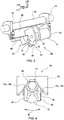
- FIG. 6 is a perspective view of the immediate lock mechanism 90, showing the immediate lock mechanism 90 in FIG. 3 viewed from the opposite side.
- FIG. 6 omits the lock-to-neutral-position mechanism 68 that is disposed behind the immediate lock mechanism 90.
- the brake plate 92 is secured to the rotatable-side supporting plate 88 so that the brake plate 92 rotates with the cushion pan 52.
- the plate clamping mechanism 94 is fixed to the seat cushion frame 18.
- the plate clamping mechanism 94 may be fixed to a bracket (not shown) that is fixed to the rear bar 50.
- FIG. 7 is a cross sectional view of the plate clamping mechanism 94.
- the plate clamping mechanism 94 includes a body 96 that has a U-shaped cross section, and a pair of brake pads 98 that are disposed inside the U-shaped recess to sandwich the brake plate 92.
- a piston 100 is unitedly provided with one of the brake pads 98.
- the piston 100 is driven by a hydraulic cylinder 102 to advance or withdraw the brake pad 98 with respect to the brake plate 92.
- the brake pads 98 clamp the brake plate 92 to stop the movement of the brake plate 92 such that the seat cushion 14 is locked. Because the plate clamping mechanism 94 can clamp the brake plate 92 regardless of the position of the brake plate 92, the seat cushion 14 can be immediately locked when desired at the current position.
- the brake pad 98 may be mechanically driven using a linkage or other means.
- FIG. 8 is a block diagram showing a configuration for controlling the locking of the seat cushion 14.
- a controller 110 receives information from a steering sensor 112 and controls the lock-to-neutral-position mechanism 68 and the immediate lock mechanism 90 based on the received information.
- the steering sensor 112 senses operation of the steering wheel by an operator of the steering wheel, or a driver (seated occupant), and outputs, to the controller 110, a steering angle that is a rotation angle of the steering wheel from the neutral position (position when the vehicle runs straight) and a steering angular velocity that is an operation speed. Alternatively, the steering angle alone may be output and the steering angular velocity may be calculated by the controller 110.
- the controller 110 controls the lock-to-neutral-position mechanism 68 and the immediate lock mechanism 90 based on the obtained information. For the lock-to-neutral-position mechanism 68, advancing and withdrawing of the retaining pin 72 are controlled by drive controlling the rotary actuator 74. For the immediate lock mechanism 90, extending and retracting of the brake pad 98 are controlled by controlling a fluid pressure.
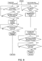
- FIG. 9 shows a control flow to lock the seat cushion 14.
- the controller 110 determines whether the steering angle is large (S100). When the driver largely turns the steering wheel such that the steering angle is larger than a predetermined value, the seat cushion 14 is locked to reduce a body movement of the driver in order to minimize the influence of the body movement to the steering operation.
- the steering angle is determined to be large in step S100, it is determined next whether the seat cushion 14 is locked by the lock-to-neutral-position mechanism 68 (S102).
- the process returns to step S100 to monitor the steering angle, because further locking by the immediate lock mechanism 90 will be redundant.
- the seat cushion 14 When the seat cushion 14 is not locked by the lock-to-neutral-position mechanism 68, the seat cushion 14 is locked at the current position by the immediate lock mechanism 90 (S104). The monitoring of the steering angle continues and when the steering wheel is determined to be at the neutral position (S106), the seat cushion 14 is released (S108). The steering angle may be determined to be at the neutral position when the steering angle is within a certain range from the neutral position.
- the controller 110 determines whether the steering velocity is high (S110).
- the lock-to-neutral-position mechanism 68 enters into a lock ready state to be ready to lock the seat cushion 14 (S112).
- the retaining pin 72 is advanced towards the retaining block 70 until the retaining pin 72 abuts against at least one of the receiving tilted surfaces 76b.
- the retaining pin 72 further advances to the bottom portion of the receiving area 76 of the retaining block 70 to lock the seat cushion 14 at the neutral position (S114).
- the seat cushion 14 is immediately locked at the neutral position. Whether the seat cushion 14 is locked at the neutral position can be determined based on the amount of advance of the retaining pin 72, which can be calculated using the rotation angle of the rotary actuator 74. Alternatively, a sensor to sense the position of the seat cushion 14 may be disposed so that the seat cushion 14 is determined to be locked at the neutral position when the retaining pin 72 has been advanced and the sensor senses that the seat cushion 14 is at the neutral position. The information of whether the seat cushion 14 is locked at the neutral position is also used in the above described step S102.
- a locking staring time may be set to the locking starting time of the lock-to-neutral-position mechanism 68.
- the locking starting time may be set to the locking starting time of the immediate lock mechanism 90.
- Locking of the seat cushion 14 during driving is specifically described.
- reduction in a body movement of the seated occupant may be desired.
- Such a reduction in the body movement is desired to be performed immediately or when the seat cushion 14 is positioned at the neutral position.
- the seat cushion 14 is immediately locked by the immediate lock mechanism 90 when the reduction of the body movement is desired, and then locked at the neutral position by the lock-to-neutral-position mechanism 68.
- the controller 110 instructs the immediate lock mechanism 90 to perform the locking. Because the immediate lock mechanism 90 can immediately lock the seat cushion 14 even when the seat cushion 14 is deviated from the neutral position, immediate locking is possible.
- the lock-to-neutral-position mechanism 68 performs the locking when the steering velocity is high.
- the immediate lock mechanism 90 temporarily locks the seat cushion 14, and then the lock-to-neutral-position mechanism 68 locks the seat cushion 14 at the neutral position. The locking by the immediate lock mechanism 90 is released when the steering wheel is returned to the neutral position, and the locking is switched over to the lock-to-neutral-position mechanism 68 that is in the lock ready state.
- the seat cushion 14 When the steering wheel is returned to the neutral position, the seat cushion 14 is likely to be returned to the neutral position. Accordingly, if the locking by the immediate lock mechanism 90 is released at this occasion, the seat cushion 14 can be expected to return to the neutral position soon after the release of the locking. When the seat cushion 14 is also at the neutral position, the seat cushion 14 is locked by the lock-to-neutral-position mechanism 68 that has been set in the lock ready state.
- the lock-to-neutral-position mechanism 68 When the steering angle is small but the steering velocity is high, the lock-to-neutral-position mechanism 68 performs the locking. For example, while the vehicle is driving at a high speed, the steering angle may be relatively small but the steering velocity may be high. While the vehicle is driving at a high speed, the seat cushion 14 can be expected to return to the neutral position relatively soon because the movement of the seat cushion 14 is small and the seat cushion 14 is near the neutral position. Accordingly, the lock-to-neutral-position mechanism 68 may be capable of locking the seat cushion 14 soon.
- the seat cushion 14 When the vehicle attempts to avoid emergency, such as when avoiding an obstacle in front of the vehicle, the seat cushion 14 is immediately locked at the current position and then locked at the neutral position. In such an attempt to avoid emergency while driving on a street (not highway), the steering angle is likely to be large and the steering velocity is likely to be high. Accordingly, locking is first performed by the immediate lock mechanism 90 and then by the lock-to-neutral-position mechanism 68. Upon elapse of a period of time sufficient to expect that the emergency has been avoided, the locking is released after waiting for the steering wheel to return to the neutral position. When the driving speed is high, such as during driving on a highway, the steering angle may not be large during an attempt to avoid emergency. Even in such a case, because the steering velocity is high, the lock-to-neutral-position mechanism 68 locks the seat cushion 14.
- FIG. 10 is a block diagram showing a configuration capable of performing a lock control of the seat cushion 14 in response to an obstacle in front of the vehicle.
- a front monitoring device 114 is added to the configuration shown in FIG. 7 .
- the controller 110 performs the control shown in FIG. 9 . While not locked during ordinary driving, the seat cushion 14 is locked when an obstacle in front of the vehicle is detected.
- the immediate lock mechanism 90 may be configured to lock the seat cushion 14 when the steering angle is large and/or the steering velocity is high. Further, the lock-to-neutral-position mechanism 68 may be configured to enter into the lock ready state when the steering angle is large and/or the steering velocity is high.
- the immediate lock mechanism is not limited to the combination of the brake plate 92 and the plate clamping mechanism 94.
- the immediate lock mechanism may have a different structure, such as a row of teeth and a claw meshing with the teeth.
- the row of teeth that may be arranged along the rotation direction of the seat cushion 14 may be fixed to the seat cushion 14 and the claw may be disposed on the seat cushion frame 18.
- the seat cushion 14 may be locked by advancing the claw to the row of teeth to mesh the claw with the teeth.
Landscapes
- Engineering & Computer Science (AREA)
- Aviation & Aerospace Engineering (AREA)
- Transportation (AREA)
- Mechanical Engineering (AREA)
- Seats For Vehicles (AREA)
Abstract
Description
- This application claims priority to Japanese Patent Application No.
2018-192402 filed on October 11, 2018 - The present disclosure relates to a vehicle seat, in particular to a seat cushion.
- A vehicle seat is known in which a seat cushions and a seat back are movable with respect to a vehicle seat frame. For example,
JP 2015-209131A - In
JP 2015-209131A - It should be noted that the above reference names and numerals in parentheses are those used in
JP 2015-209131A - During driving of a vehicle, it may be desired to promptly lock a seat cushion at a current position. In contrast, it may be desired to lock the seat cushion at a neutral position.
- The present disclosure provides a vehicle sheet cushion that is first locked at a current position, and then at a neutral position.
- A vehicle seat according to an embodiment of the present application includes a main frame, and a seat cushion that is rotatably supported by the main frame. The vehicle seat also includes a first lock mechanism that locks the seat cushion in accordance with a steering operation and releases the seat cushion when a steering wheel is in vicinity of a neutral position. The vehicle seat further includes a second lock mechanism that enters into a lock ready state to be ready to lock the seat cushion in accordance with a steering operation and locks the seat cushion at the neutral position when the seat cushion is at the neutral position.
- In this way, the sheet cushion can be first locked at a current position and then at the neutral position.
- The first lock mechanism may lock the seat cushion when a steering angle is larger than or equal to a predetermined value. The second lock mechanism may enter into the lock ready state to be ready to lock the seat cushion when a steering angular velocity is larger than or equal to a predetermined value. In this way, the seat cushion can be locked when the steering angle is large. Even with a small steering angle such as when driving at a high speed, the seat cushion can still be locked as long as the operation speed is high.
- The first lock mechanism may be configured not to lock the seat cushion while the seat cushion is locked by the second lock mechanism. In this way, unnecessary locking operations by the first lock mechanism can be avoided.
- The first and second lock mechanisms may be allowed to operate when an obstacle in front of the vehicle is detected. In this way, while the seat cushion is not locked during ordinary driving, the seat cushion can be locked when avoiding an obstacle.
- The first lock mechanism may include a plate fixed to either one of the main frame and the seat cushion, and a plate clamping mechanism fixed to the other of the main frame and the seat cushion. The plate clamping mechanism may lock the seat cushion by clamping the plate.
- The second lock mechanism may include a single retaining element disposed on either one of the main frame and the seat cushion, a receiving element disposed on the other of the main frame and the seat cushion, and a drive element that drives at least one of the retaining element and the receiving element to relatively advance or withdraw the retaining element with respect to the receiving element. The receiving element may include a single recessed receiving area in which the retaining element is received such that the seat cushion is locked at a neutral position when the retaining element is engaged at the bottom of the receiving area. The receiving element may further include two side surfaces that oppose each other in a rotation direction of the seat cushion. The two side surfaces have receiving tilted surfaces that are tilted towards each other to be closer from the opening top to the bottom of the receiving area to thereby guide the retaining element towards the bottom.
- Embodiment(s) of the present disclosure will be described by reference to the following figures, wherein:
-
FIG. 1 is an exploded perspective diagram of a vehicle seat according to an embodiment of the present disclosure; -
FIG. 2 is a perspective diagram of the vehicle seat according to the embodiment of the present disclosure, viewed from a rear and lower position; -
FIG. 3 is a perspective diagram showing details of a lock-to-neutral-position mechanism; -
FIG. 4 is a diagram of the lock-to-neutral-position mechanism viewed from the front; -
FIG. 5 is a diagram to describe operation of the lock-to-neutral-position mechanism; -
FIG. 6 is a perspective diagram showing details of an immediate lock mechanism; -
FIG. 7 is a cross-sectional diagram showing a plate clamping mechanism of the immediate lock mechanism; -
FIG. 8 is a block diagram showing a configuration for a seat cushion lock control; -
FIG. 9 is a flowchart showing a control flow of the lock-to-neutral-position mechanism and the immediate lock mechanism; and -
FIG. 10 is a block diagram showing another configuration for the seat cushion lock control. - A
vehicle seat 10 according to an embodiment of the present disclosure is described below by reference to the drawings. In the description below, unless otherwise specified, the terms describing relative positions and orientations such as front, forward, rear, rearward, left, leftward, right, rightward, up, upward, down, and downward respectively refer to positions and orientations from the perspective of an occupant who is sitting in the vehicle seat 10 (hereinafter referred to as a "seated occupant"). In each drawing, the arrows FR, UP, and LH indicate the front, up, and left, respectively. -
FIGs. 1 and2 are perspective views schematically showing a simplified structure of thevehicle seat 10.FIG. 1 is a diagram showing thevehicle seat 10 viewed down from a left front position, with some parts disassembled.FIG. 2 is a diagram of thevehicle seat 10 viewed up from a left rear position. Thevehicle seat 10 is a seat used for an automobile such as a passenger car. Thevehicle seat 10 includes amain frame 12 that is directly mounted on a vehicle body, and aseat cushion 14 and aseat back 16 that are movably supported by themain frame 12. InFIG. 1 , theseat cushion 14 is illustrated to allow the internal structure to be viewed through. Theseat cushion 14 supports the buttocks and the thighs of a seated occupant from below, while the seat back 16 supports the upper body of the seated occupant from the rear. - The
main frame 12 includes aseat cushion frame 18 that supports theseat cushion 14, and aseat back frame 20 that supports the seat back 16. Theseat cushion frame 18 includesseat legs 22 respectively at bottom four corners. Theseat legs 22 are slidably coupled to a pair offloor rails 26 that are fixed on avehicle floor 24 and extend along a longitudinal axis of the vehicle. In this way, thevehicle seat 10 is mounted on thefloor 24 so that thevehicle seat 10 is slidable along the longitudinal axis of the vehicle. Theseat back frame 20 has an inverted U-shape when viewed from the front. The bottom ends of theseat back frame 20 are connected to the rear ends of theseat cushion frame 18. Theseat back frame 20 is coupled to theseat cushion frame 18 so that theseat back frame 20 is pivotable about a lateral axis of the vehicle. The tilting angle of the seat back 16 can be adjusted by pivoting the seat backframe 20 with respect to theseat cushion frame 18. - The seat back 16 includes a seat back
subframe 28 suspended from the seat backframe 20, and a seat backpad 30 attached to the seat backsubframe 28. The seat backsubframe 28 includes a pair ofvertical members 32 that extend substantially along a vertical axis of the vehicle, respectively on the right and left sides of thevehicle seat 10, and twohorizontal members vertical members 32. Of the two horizontal members, the upper horizontal member is referred to as an upperhorizontal member 34U, whereas the lower horizontal member is referred to as a lowerhorizontal member 34L. The upperhorizontal member 34U is connected between the twovertical members 32 at a position slightly above the vertical center of thevertical members 32, whereas the lowerhorizontal member 34L is connected at lower ends of the twovertical members 32. Twospring housing brackets 36 that protrude rearward are fixed at the right and left ends of the upperhorizontal member 34U. A rear end of areturn spring 38 that is a leaf spring is fixed to a rear end of each of thespring housing brackets 36, while a front end of each of thereturn spring 38 is fixed to the seat backframe 20. The leaf return springs 38 are disposed so that the thickness direction is along the lateral axis. A deflection of the return springs 38 allows a rightward or leftward movement of the seat backsubframe 28 with respect to the seat backframe 20. An elastic force of the return springs 38 returns the seat backsubframe 28 to a neutral position that is at the lateral center of thevehicle seat 10. - The seat back
subframe 28 is suspended from the seat backframe 20 viamultiple wires intermediate disc 42 is supported by being suspended from the seat backframe 20 with two pairs ofsuspension wires subframe 28 is suspended from theintermediate disc 42 with twosuspension wires 40C, one each on the right and left. Theintermediate disc 42 is attached to a rear surface of the seat backpad 30. The seat back 16 swings like a pendulum with theintermediate disc 42 serving as the pivot point. Each of thesuspension wires 40A is a seamlessly looped wire passing at two points on the seat backframe 20 and through theintermediate disc 42. Both ends of each of thesuspension wires 40B are connected at two points on the seat backframe 20 and a middle portion passes through theintermediate disc 42. One end of each of thesuspension wires 40C is connected to the upperhorizontal member 34U of the seat backsubframe 28, whereas the other end is connected to the lowerhorizontal member 34L, with a middle portion passing through theintermediate disc 42. -
Multiple bridging wires 44 are laterally stretched between the right and leftvertical members 32 of the seat backsubframe 28. The bridgingwires 44 support the seat backpad 30 from behind and receive a load from a seated occupant. The bridgingwires 44 are omitted inFIG. 2 . - The
seat cushion frame 18 includes a pair of longitudinally extendingside plates 46, respectively on the right and left of theseat cushion 14, and twobars side plates 46 on the right and left. Of the twobars front bar 48 connects theside plates 46 at front end portions of theside plates 46. Therear bar 50 connects theside plates 46 at rear end portions of theside plates 46. - The
seat cushion 14 includes acushion pan 52 movably supported by theseat cushion frame 18, and acushion pad 54 attached on thecushion pan 52. Thecushion pan 52 is supported by theseat cushion frame 18 via a front supportingmechanism 56 and a rear supportingmechanism 64. The front supportingmechanism 56 includes abracket 58 fixed to thefront bar 48, abearing 60 fixed to thebracket 58, and anaxle 62 fixed to thecushion pan 52. Theaxle 62 is rotatably supported by the bearing 60 so that thecushion pan 52 is rotatable about an axis A of theaxle 62. The axis A is tilted so that the axis A extends through the lumber region of a seated occupant and the front end is lowered. The rear supportingmechanism 64 includes aguide rail 66 fixed to thecushion pan 52, and tworollers 67 fixed to theseat cushion frame 18. The drawings only show main parts of the rear supportingmechanism 64, while minor parts are omitted, such as an element to support therollers 67. Theguide rail 66 has a guide surface that has an arch-shape curved about the axis A. The tworollers 67 are in contact with the guide surface of theguide rail 66. By being supported by the front supportingmechanism 56 and the rear supportingmechanism 64, thecushion pan 52 rotates about the axis A. The axis A is also referred to as a rotation axis A. - The
vehicle seat 10 further includes twolock mechanisms seat cushion 14. Thelock mechanism 68 is a mechanism to lock theseat cushion 14 at the neutral position in which theseat cushion 14 is not laterally tilted (in other words, theseat cushion 14 is horizontally oriented). Thelock mechanism 68 is hereinafter referred to as a lock-to-neutral-position mechanism 68. Thelock mechanism 90 can immediately lock theseat cushion 14 at any position. Thelock mechanism 90 is hereinafter referred to as animmediate lock mechanism 90.FIG. 2 only shows main elements of the lock-to-neutral-position mechanism 68 and theimmediate lock mechanism 90. - The lock-to-neutral-
position mechanism 68 includes a retainingblock 70 fixed on thecushion pan 52, a retainingpin 72 that is disposed on theseat cushion frame 18 and engageable to the retainingblock 70, and a rotary solenoid actuator 74 (hereinafter referred to as a rotary actuator 74) that drives the retainingpin 72. The retainingblock 70 includes a single receiving area 76 (refer toFIG. 4 ) that has a V-groove shape. The retainingpin 72 is advanced to or withdrawn from the receivingarea 76 by therotary actuator 74. When the retainingpin 72 advances to be engaged at a bottom portion of the receivingarea 76, theseat cushion 14 is locked at a position that is set according to the position of the receivingarea 76. In thevehicle seat 10 according to the present embodiment, theseat cushion 14 is locked at a neutral position; that is, in a horizontal orientation. The retainingblock 70 serves as a receiving element that includes the receivingarea 76 in which the retainingpin 72 serving as a retaining element is received. Alternatively, the retainingblock 70 may be disposed on theseat cushion frame 18, whereas the retainingpin 72 and therotary actuator 74 may be disposed on the cushion pan. In another configuration, the retainingpin 72 may be fixed and the retainingblock 70 may be advanced to or withdrawn from the retainingpin 72. The structure of the lock-to-neutral-position mechanism 68 is described in detail further below. - The
immediate lock mechanism 90 includes abrake plate 92 that is fixed on thecushion pan 52, and aplate clamping mechanism 94 that is disposed on theseat cushion frame 18 and secures thecushion pan 52 by clamping thebrake plate 92. Alternatively, thebrake plate 92 may be disposed on theseat cushion frame 18, and theplate clamping mechanism 94 may be disposed on thecushion pan 52. The structure of theimmediate lock mechanism 90 is described in detail further below. -
FIG. 3 is a perspective view showing the structure of the lock-to-neutral-position mechanism 68 in further detail.FIG. 3 omits theimmediate lock mechanism 90 that is disposed behind the lock-to-neutral-position mechanism 68.FIG. 4 shows the retainingblock 70 and retainingpin 72 viewed slightly upward from the front. A fixed-side supporting plate 80 is fixed to therear bar 50 of theseat cushion frame 18 via two fixingbrackets 78. The fixed-side supporting plate 80 supports the retainingpin 72 and therotary actuator 74 via three fixingplates 82. Each of the fixingplates 82 is fixed by a bolt from the back side of the fixed-side supporting plate 80. One of the fixingplates 82 is disposed between therotary actuator 74 and the retainingpin 72, another fixingplate 82 is disposed on the opposite end of therotary actuator 74, and the remaining fixingplate 82 is disposed on the opposite side of the retainingpin 72. In this way, both the right and left sides of therotary actuator 74 and the retainingpin 72 are respectively supported by the fixingplates 82. The retainingpin 72 includes a square-column shapedarm 84, and aring 86 disposed on the distal end of thearm 84. Thering 86 is rotatably attached to thearm 84 so that thering 86 is rotatable about an axis in parallel to the centerline of thearm 84. Thering 86 may be structured with a ball bearing. The inner race of the ball bearing may be coupled to the end surface of thearm 84 with a bolt or other means. In such a case, an outer race of the ball bearing is rotatable with respect to thearm 84. - The retaining
block 70 is fixed to a rotatable-side supporting plate 88 that is fixed on thecushion pan 52. The retainingblock 70 includes the V-groove shaped receivingarea 76 that is opened downwardly. In the receivingarea 76, twoside surfaces 76a that form the V shape are opposed each other in the rotation direction B of theseat cushion 14 such that the side surfaces 76a are tilted towards each other to be closer from a top to the bottom of the V shape opening. These tilted surfaces are referred to as receiving tiltedsurfaces 76b. In the present embodiment, the entire side surfaces 76a are the receiving tiltedsurfaces 76b. - The retaining
pin 72 is driven by therotary actuator 74 such that the distal end of the retainingpin 72 is advanced to or withdrawn from the receivingarea 76 of the retainingblock 70. InFIG. 4 , the position in dash-dot lines show a withdrawn position, whereas the position in solid lines show an advanced position. In the advanced position, the retainingpin 72 comes into contact with the side surfaces 76a on both sides at the bottom of the receivingarea 76 to secure the retainingblock 70 at this position in the rotating direction. In this way, theseat cushion 14 is locked. In thevehicle seat 10 according to the present embodiment, theseat cushion 14 is disposed at the neutral position in the horizontal orientation along the lateral axis when theseat cushion 14 is locked by the lock-to-neutral-position mechanism 68. -
FIG. 5 shows an engaging process of the retainingpin 72. The retainingblock 70 is deviated from a neutral position N. The opening of the retainingblock 70 is designed to have dimensions so that the receivingarea 76 can receive the retainingpin 72 regardless of the position of theseat cushion 14. In this way, when the retainingpin 72 is advanced towards the retainingblock 70 with theseat cushion 14 deviated from the neutral position, such as at the furthest position in the rotational range, the retainingpin 72 abuts against one of the receiving tiltedsurfaces 76b. The retainingpin 72 that abuts against the receiving tiltedsurface 76b applies a force F1 to the retainingblock 70. This force F1 and a movement of theseat cushion 14 caused by a movement of the vehicle or a seated occupant move the retainingblock 70 to the neutral position as the retainingpin 72 advances. The retainingpin 72 stops when the retainingpin 72 abuts against both of the right and left receiving tiltedsurfaces 76b. The position of the retainingblock 70 at this occasion is the neutral position N. Theseat cushion 14 becomes rotatable by withdrawing the retainingpin 72 from the bottom of the receivingarea 76. - The
ring 86 is rotated while the retainingpin 72 is guided along the receiving tiltedsurface 76b. In this way, a friction that would be caused by a movement of the retainingpin 72 is reduced. Further, a flexible material such as rubber may be attached on the receiving tiltedsurfaces 76b or around the outer circumference of thering 86. In this way, an impact noise is reduced when the retainingpin 72 impacts on the retainingblock 70. -
FIG. 6 is a perspective view of theimmediate lock mechanism 90, showing theimmediate lock mechanism 90 inFIG. 3 viewed from the opposite side.FIG. 6 omits the lock-to-neutral-position mechanism 68 that is disposed behind theimmediate lock mechanism 90. Thebrake plate 92 is secured to the rotatable-side supporting plate 88 so that thebrake plate 92 rotates with thecushion pan 52. Theplate clamping mechanism 94 is fixed to theseat cushion frame 18. For example, theplate clamping mechanism 94 may be fixed to a bracket (not shown) that is fixed to therear bar 50. -
FIG. 7 is a cross sectional view of theplate clamping mechanism 94. Theplate clamping mechanism 94 includes abody 96 that has a U-shaped cross section, and a pair ofbrake pads 98 that are disposed inside the U-shaped recess to sandwich thebrake plate 92. Apiston 100 is unitedly provided with one of thebrake pads 98. Thepiston 100 is driven by ahydraulic cylinder 102 to advance or withdraw thebrake pad 98 with respect to thebrake plate 92. Thebrake pads 98 clamp thebrake plate 92 to stop the movement of thebrake plate 92 such that theseat cushion 14 is locked. Because theplate clamping mechanism 94 can clamp thebrake plate 92 regardless of the position of thebrake plate 92, theseat cushion 14 can be immediately locked when desired at the current position. Other than the hydraulic driving, thebrake pad 98 may be mechanically driven using a linkage or other means. -
FIG. 8 is a block diagram showing a configuration for controlling the locking of theseat cushion 14. Acontroller 110 receives information from asteering sensor 112 and controls the lock-to-neutral-position mechanism 68 and theimmediate lock mechanism 90 based on the received information. - The
steering sensor 112 senses operation of the steering wheel by an operator of the steering wheel, or a driver (seated occupant), and outputs, to thecontroller 110, a steering angle that is a rotation angle of the steering wheel from the neutral position (position when the vehicle runs straight) and a steering angular velocity that is an operation speed. Alternatively, the steering angle alone may be output and the steering angular velocity may be calculated by thecontroller 110. Thecontroller 110 controls the lock-to-neutral-position mechanism 68 and theimmediate lock mechanism 90 based on the obtained information. For the lock-to-neutral-position mechanism 68, advancing and withdrawing of the retainingpin 72 are controlled by drive controlling therotary actuator 74. For theimmediate lock mechanism 90, extending and retracting of thebrake pad 98 are controlled by controlling a fluid pressure. -
FIG. 9 shows a control flow to lock theseat cushion 14. In controlling theimmediate lock mechanism 90, thecontroller 110 determines whether the steering angle is large (S100). When the driver largely turns the steering wheel such that the steering angle is larger than a predetermined value, theseat cushion 14 is locked to reduce a body movement of the driver in order to minimize the influence of the body movement to the steering operation. When the steering angle is determined to be large in step S100, it is determined next whether theseat cushion 14 is locked by the lock-to-neutral-position mechanism 68 (S102). When theseat cushion 14 is locked by the lock-to-neutral-position mechanism 68, the process returns to step S100 to monitor the steering angle, because further locking by theimmediate lock mechanism 90 will be redundant. When theseat cushion 14 is not locked by the lock-to-neutral-position mechanism 68, theseat cushion 14 is locked at the current position by the immediate lock mechanism 90 (S104). The monitoring of the steering angle continues and when the steering wheel is determined to be at the neutral position (S106), theseat cushion 14 is released (S108). The steering angle may be determined to be at the neutral position when the steering angle is within a certain range from the neutral position. - In controlling the lock-to-neutral-
position mechanism 68, thecontroller 110 determines whether the steering velocity is high (S110). When the driver rapidly turns the steering wheel such that the steering angular velocity is higher than a predetermined angular velocity, the lock-to-neutral-position mechanism 68 enters into a lock ready state to be ready to lock the seat cushion 14 (S112). Specifically, the retainingpin 72 is advanced towards the retainingblock 70 until the retainingpin 72 abuts against at least one of the receiving tiltedsurfaces 76b. Under such conditions, when theseat cushion 14 is moved to be at the neutral position, the retainingpin 72 further advances to the bottom portion of the receivingarea 76 of the retainingblock 70 to lock theseat cushion 14 at the neutral position (S114). Naturally, when theseat cushion 14 is at the neutral position when the retainingpin 72 is first driven, theseat cushion 14 is immediately locked at the neutral position. Whether theseat cushion 14 is locked at the neutral position can be determined based on the amount of advance of the retainingpin 72, which can be calculated using the rotation angle of therotary actuator 74. Alternatively, a sensor to sense the position of theseat cushion 14 may be disposed so that theseat cushion 14 is determined to be locked at the neutral position when the retainingpin 72 has been advanced and the sensor senses that theseat cushion 14 is at the neutral position. The information of whether theseat cushion 14 is locked at the neutral position is also used in the above described step S102. - Next, it is determined whether a predetermined time period has been elapsed after the
seat cushion 14 is locked (S116). A locking staring time may be set to the locking starting time of the lock-to-neutral-position mechanism 68. Alternatively, when the locking is performed by the lock-to-neutral-position mechanism 68 after the locking by theimmediate lock mechanism 90, the locking starting time may be set to the locking starting time of theimmediate lock mechanism 90. When the predetermined time has elapsed after the locking and the steering angle is at the neutral position (S118), the locking is released (S120). - Locking of the
seat cushion 14 during driving is specifically described. When the steering wheel is turned largely or rapidly, reduction in a body movement of the seated occupant may be desired. Such a reduction in the body movement is desired to be performed immediately or when theseat cushion 14 is positioned at the neutral position. In thevehicle seat 10, theseat cushion 14 is immediately locked by theimmediate lock mechanism 90 when the reduction of the body movement is desired, and then locked at the neutral position by the lock-to-neutral-position mechanism 68. - When the steering angle is large, the
controller 110 instructs theimmediate lock mechanism 90 to perform the locking. Because theimmediate lock mechanism 90 can immediately lock theseat cushion 14 even when theseat cushion 14 is deviated from the neutral position, immediate locking is possible. The lock-to-neutral-position mechanism 68 performs the locking when the steering velocity is high. When the steering angle is large and the steering velocity is high, theimmediate lock mechanism 90 temporarily locks theseat cushion 14, and then the lock-to-neutral-position mechanism 68 locks theseat cushion 14 at the neutral position. The locking by theimmediate lock mechanism 90 is released when the steering wheel is returned to the neutral position, and the locking is switched over to the lock-to-neutral-position mechanism 68 that is in the lock ready state. When the steering wheel is returned to the neutral position, theseat cushion 14 is likely to be returned to the neutral position. Accordingly, if the locking by theimmediate lock mechanism 90 is released at this occasion, theseat cushion 14 can be expected to return to the neutral position soon after the release of the locking. When theseat cushion 14 is also at the neutral position, theseat cushion 14 is locked by the lock-to-neutral-position mechanism 68 that has been set in the lock ready state. - When the steering angle is small but the steering velocity is high, the lock-to-neutral-
position mechanism 68 performs the locking. For example, while the vehicle is driving at a high speed, the steering angle may be relatively small but the steering velocity may be high. While the vehicle is driving at a high speed, theseat cushion 14 can be expected to return to the neutral position relatively soon because the movement of theseat cushion 14 is small and theseat cushion 14 is near the neutral position. Accordingly, the lock-to-neutral-position mechanism 68 may be capable of locking theseat cushion 14 soon. - When the steering angle is large but the steering velocity is low, after the locking is performed by the
immediate lock mechanism 90 and released, no locking is performed by the lock-to-neutral-position mechanism 68, such that theseat cushion 14 is left unlocked. For example, when the vehicle turns at an intersection, the steering angle is large, but the steering velocity is not high. Under such conditions, theseat cushion 14 is temporarily locked but released soon after passing the intersection. - When the vehicle attempts to avoid emergency, such as when avoiding an obstacle in front of the vehicle, the
seat cushion 14 is immediately locked at the current position and then locked at the neutral position. In such an attempt to avoid emergency while driving on a street (not highway), the steering angle is likely to be large and the steering velocity is likely to be high. Accordingly, locking is first performed by theimmediate lock mechanism 90 and then by the lock-to-neutral-position mechanism 68. Upon elapse of a period of time sufficient to expect that the emergency has been avoided, the locking is released after waiting for the steering wheel to return to the neutral position. When the driving speed is high, such as during driving on a highway, the steering angle may not be large during an attempt to avoid emergency. Even in such a case, because the steering velocity is high, the lock-to-neutral-position mechanism 68 locks theseat cushion 14. - The locking of the
seat cushion 14 described above may be performed when an obstacle in front of the vehicle is detected.FIG. 10 is a block diagram showing a configuration capable of performing a lock control of theseat cushion 14 in response to an obstacle in front of the vehicle. In the configuration shown inFIG. 10 , afront monitoring device 114 is added to the configuration shown inFIG. 7 . When thefront monitoring device 114 detects an obstacle in front of the vehicle, the information is sent to thecontroller 110. In response to the detection of the front obstacle, thecontroller 110 performs the control shown inFIG. 9 . While not locked during ordinary driving, theseat cushion 14 is locked when an obstacle in front of the vehicle is detected. - The
immediate lock mechanism 90 may be configured to lock theseat cushion 14 when the steering angle is large and/or the steering velocity is high. Further, the lock-to-neutral-position mechanism 68 may be configured to enter into the lock ready state when the steering angle is large and/or the steering velocity is high. - The immediate lock mechanism is not limited to the combination of the
brake plate 92 and theplate clamping mechanism 94. The immediate lock mechanism may have a different structure, such as a row of teeth and a claw meshing with the teeth. The row of teeth that may be arranged along the rotation direction of theseat cushion 14 may be fixed to theseat cushion 14 and the claw may be disposed on theseat cushion frame 18. Theseat cushion 14 may be locked by advancing the claw to the row of teeth to mesh the claw with the teeth. - 10 vehicle seat, 12 main frame, 14 seat cushion, 16 seat back, 18 seat cushion frame, 20 seat back frame, 46 side plate, 48 front bar, 50 rear bar, 52 cushion pan, 54 cushion pad, 56 front supporting mechanism, 58 bracket, 60 bearing, 62 axle, 64 rear supporting mechanism, 66 guide rail, 67 roller, 68 lock-to-neutral-position mechanism (second lock mechanism), 70 retaining block (receiving element), 72 retaining pin (retaining element), 74 rotary actuator, 76 receiving area, 76a side surface, 76b receiving tilted surface, 78 fixing bracket, 80 fixed-side supporting plate, 82 fixing plate, 84 arm, 86 ring, 88 rotatable-side supporting plate, 90 immediate lock mechanism (first lock mechanism), 92 brake plate, 94 plate clamping mechanism, 96 body, 98 brake pad, 100 piston, 102 hydraulic cylinder, 110 controller, 112 steering sensor, and 114 front monitoring device.
Claims (6)
- A vehicle seat (10) comprising:a main frame (12);a seat cushion (14) rotatably supported by the main frame (12);a first lock mechanism (90) configured to lock the seat cushion (14) in accordance with a steering operation and to release the seat cushion (14) when a steering wheel is in vicinity of a neutral position; anda second lock mechanism (68) configured to enter into a lock ready state to be ready to lock the seat cushion (14) in accordance with a steering operation and to lock the seat cushion (14) at the neutral position when the seat cushion (14) is at the neutral position.
- The vehicle seat (10) according to claim 1, whereinthe first lock mechanism (90) is configured to lock the seat cushion (14) when a steering angle is larger than or equal to a predetermined value, andthe second lock mechanism (68) is configured to enter in the lock ready state to be ready to lock the seat cushion (14) when a steering angular velocity is larger than or equal to a predetermined value.
- The vehicle seat (10) according to claim 1 or 2, wherein
the first lock mechanism (90) is configured to not lock the seat cushion (14) while the second lock mechanism (68) locks the seat cushion (14). - The vehicle seat (10) according to any one of claims 1 to 3, wherein
the first lock mechanism (90) and the second lock mechanism (68) are configured to be allowed to be operated when an obstacle in front of a vehicle is detected. - The vehicle seat (10) according to any one of claims 1 to 4, wherein
the first lock mechanism (90) comprisesa plate (92) fixed to either one of the main frame (12) and the seat cushion (14), anda plate clamping mechanism (94) fixed to the other of the main frame (12) and the seat cushion (14), the plate clamping mechanism (94) being configured to lock the seat cushion (14) by clamping the plate (92). - The vehicle seat (10) according to any one of claims 1 to 5, wherein
the second lock mechanism (68) comprisesa single retaining element (72) disposed on either one of the main frame (12) and the seat cushion (14),a receiving element (70) disposed on the other of the main frame (12) and the seat cushion (14), the receiving element (70) comprisinga single recessed receiving area (76) in which the retaining element (72) is received such that the seat cushion (14) is locked at a neutral position when the retaining element (72) is engaged at a bottom of the receiving area (76), andtwo side surfaces (76a) opposing each other in a rotation direction of the seat cushion (14), the two side surfaces (76a) having receiving tilted surfaces (76b) that are tilted towards each other to be closer from a top to the bottom of the receiving area (76) to guide the receiving element (70) towards the bottom, anda drive element (74) configured to drive at least one of the retaining element (72) and the receiving element (70) to relatively advance or withdraw the retaining element (72) with respect to the receiving element (70).
Applications Claiming Priority (1)
| Application Number | Priority Date | Filing Date | Title |
|---|---|---|---|
| JP2018192402A JP7047699B2 (en) | 2018-10-11 | 2018-10-11 | Vehicle seat |
Publications (2)
| Publication Number | Publication Date |
|---|---|
| EP3636485A1 true EP3636485A1 (en) | 2020-04-15 |
| EP3636485B1 EP3636485B1 (en) | 2022-03-23 |
Family
ID=68280801
Family Applications (1)
| Application Number | Title | Priority Date | Filing Date |
|---|---|---|---|
| EP19202657.3A Active EP3636485B1 (en) | 2018-10-11 | 2019-10-11 | Vehicle seat |
Country Status (4)
| Country | Link |
|---|---|
| US (1) | US11458874B2 (en) |
| EP (1) | EP3636485B1 (en) |
| JP (1) | JP7047699B2 (en) |
| CN (1) | CN111038343B (en) |
Families Citing this family (4)
| Publication number | Priority date | Publication date | Assignee | Title |
|---|---|---|---|---|
| KR102518806B1 (en) * | 2018-11-26 | 2023-04-05 | 현대자동차주식회사 | Multi-joint seat back for vehicle |
| JP7140084B2 (en) * | 2019-09-25 | 2022-09-21 | トヨタ自動車株式会社 | In-vehicle seat device |
| CN111251958A (en) * | 2020-03-19 | 2020-06-09 | 徐庆 | Cushion structure capable of adjusting soft and hard sitting feeling |
| US11603828B2 (en) * | 2021-03-23 | 2023-03-14 | Toyota Motor Engineering & Manufacturing North America, Inc. | Overstress protection for shape memory alloy seat actuator |
Citations (3)
| Publication number | Priority date | Publication date | Assignee | Title |
|---|---|---|---|---|
| JPH0325035A (en) * | 1989-06-20 | 1991-02-01 | Mazda Motor Corp | Seat device for vehicle |
| JP2015209131A (en) | 2014-04-25 | 2015-11-24 | トヨタ自動車株式会社 | Vehicle seat control device and vehicle seat device |
| EP3275725A1 (en) * | 2016-07-25 | 2018-01-31 | Toyota Jidosha Kabushiki Kaisha | Vehicle seat |
Family Cites Families (26)
| Publication number | Priority date | Publication date | Assignee | Title |
|---|---|---|---|---|
| JPS61285147A (en) * | 1985-06-11 | 1986-12-15 | Kunimatsu Kogyo Kk | Automatic adjusting device for side support in vehicle seat assembly |
| DE10022434A1 (en) * | 2000-05-09 | 2001-11-22 | Daimler Chrysler Ag | Dynamic adaptation of vehicle seat to support body when cornering, determines adjustment from stored and current road and vehicle data, allowing for inherent delay |
| RU2203813C2 (en) * | 2001-06-13 | 2003-05-10 | Государственный научно-исследовательский тракторный институт НАТИ | Vehicle seat side tilting adjuster |
| CN2585781Y (en) * | 2002-12-19 | 2003-11-12 | 严庆 | Automotive driver's cushion regulation mechanism |
| JP5018149B2 (en) * | 2006-04-26 | 2012-09-05 | 日産自動車株式会社 | Driver feeling adjustment device |
| JP2008137551A (en) * | 2006-12-04 | 2008-06-19 | Aisin Seiki Co Ltd | Vehicular seat device |
| JP5363156B2 (en) * | 2009-03-24 | 2013-12-11 | 株式会社オーテックジャパン | Vehicle seat |
| JP2012111277A (en) * | 2010-11-22 | 2012-06-14 | Denso Corp | Vehicular seat control device |
| EP2743122B1 (en) * | 2011-08-10 | 2019-02-20 | Toyota Jidosha Kabushiki Kaisha | Vehicle seat apparatus |
| EP3412503B1 (en) * | 2011-08-31 | 2023-01-25 | TS Tech Co., Ltd. | Seat apparatus |
| US9376040B2 (en) * | 2011-12-20 | 2016-06-28 | Toyota Jidosha Kabushiki Kaisha | Vehicular seat |
| JP5598557B2 (en) | 2013-01-10 | 2014-10-01 | トヨタ自動車株式会社 | Vehicle seat device |
| JP5987989B2 (en) * | 2013-07-24 | 2016-09-07 | トヨタ自動車株式会社 | Sheet |
| JP2015131605A (en) * | 2014-01-15 | 2015-07-23 | トヨタ紡織株式会社 | Vehicle seat |
| JP6098576B2 (en) * | 2014-06-20 | 2017-03-22 | トヨタ自動車株式会社 | Vehicle seat |
| JP6372398B2 (en) * | 2015-03-10 | 2018-08-15 | マツダ株式会社 | vehicle |
| US10988052B2 (en) * | 2015-05-12 | 2021-04-27 | Nissan Motor Co., Ltd. | Seat for vehicle |
| JP6512196B2 (en) * | 2016-09-15 | 2019-05-15 | トヨタ自動車株式会社 | Vehicle seat |
| CN106494266B (en) * | 2016-12-06 | 2018-08-24 | 重庆电子工程职业学院 | Rotatable automotive seat when turning |
| JP2018176902A (en) * | 2017-04-07 | 2018-11-15 | 本田技研工業株式会社 | Vehicle control system, vehicle control method and vehicle control program |
| DE102017208601A1 (en) * | 2017-05-22 | 2018-11-22 | Bayerische Motoren Werke Aktiengesellschaft | Adjustable seat |
| US11400834B2 (en) * | 2018-02-02 | 2022-08-02 | State Farm Mutual Automobile Insurance Company | Adjusting interior configuration of a vehicle based on external environment data |
| DE102018108488B4 (en) * | 2018-04-10 | 2022-01-27 | Dr. Ing. H.C. F. Porsche Aktiengesellschaft | Motor vehicle with a pedal console and a seat |
| WO2019234014A1 (en) * | 2018-06-06 | 2019-12-12 | Adient Engineering and IP GmbH | Seat tilting system |
| US11807183B2 (en) * | 2018-10-23 | 2023-11-07 | Ts Tech Co., Ltd. | Occupant protection apparatus |
| WO2021026765A1 (en) * | 2019-08-13 | 2021-02-18 | SZ DJI Technology Co., Ltd. | Predictive control system for a vehicle |
-
2018
- 2018-10-11 JP JP2018192402A patent/JP7047699B2/en active Active
-
2019
- 2019-10-09 US US16/596,887 patent/US11458874B2/en active Active
- 2019-10-09 CN CN201910954025.8A patent/CN111038343B/en active Active
- 2019-10-11 EP EP19202657.3A patent/EP3636485B1/en active Active
Patent Citations (3)
| Publication number | Priority date | Publication date | Assignee | Title |
|---|---|---|---|---|
| JPH0325035A (en) * | 1989-06-20 | 1991-02-01 | Mazda Motor Corp | Seat device for vehicle |
| JP2015209131A (en) | 2014-04-25 | 2015-11-24 | トヨタ自動車株式会社 | Vehicle seat control device and vehicle seat device |
| EP3275725A1 (en) * | 2016-07-25 | 2018-01-31 | Toyota Jidosha Kabushiki Kaisha | Vehicle seat |
Also Published As
| Publication number | Publication date |
|---|---|
| JP7047699B2 (en) | 2022-04-05 |
| JP2020059419A (en) | 2020-04-16 |
| EP3636485B1 (en) | 2022-03-23 |
| CN111038343B (en) | 2022-01-11 |
| US20200114795A1 (en) | 2020-04-16 |
| US11458874B2 (en) | 2022-10-04 |
| CN111038343A (en) | 2020-04-21 |
Similar Documents
| Publication | Publication Date | Title |
|---|---|---|
| EP3636485B1 (en) | Vehicle seat | |
| US7195313B2 (en) | Crash-active headrest | |
| US5340185A (en) | Vehicle safety seat having a raisable front edge | |
| JP5104161B2 (en) | Vehicle seat | |
| US7607735B2 (en) | Vehicle seats | |
| US20040075312A1 (en) | Vehicle seat assembly having a cradle seat back | |
| US7648200B2 (en) | Headrest device | |
| EP2952381B1 (en) | Vehicle seat control device and vehicle seat device | |
| CN101332779B (en) | Vehicle seat special for double door vehicle and capable of moving forwards | |
| EP3774441B1 (en) | Manual pitch easy-entry seat with power return | |
| EP3344490B1 (en) | Vehicle seat assembly | |
| EP1259397B1 (en) | Vehicle seat assembly having a cradle seat back | |
| US10640016B2 (en) | Seat adjuster for vehicle seat | |
| JP4692036B2 (en) | Car movable floor equipment | |
| JP4678674B2 (en) | Vehicle driver's seat | |
| JP4613293B2 (en) | Vehicle driver's seat | |
| JP2584934B2 (en) | Safety devices for vehicle seats | |
| JP4496414B2 (en) | Vehicle seat | |
| JP2820941B2 (en) | Front seat rotating device for automobiles | |
| US11912181B2 (en) | Suspension seat | |
| CN1286682C (en) | Articulated lever construction for a seat frame | |
| JP4496917B2 (en) | A vehicle seat device and an occupant operation assisting method for a vehicle seat. | |
| JP2020124959A (en) | Cushion frame | |
| JP2013001347A (en) | Lift-up seat for vehicle | |
| JPH0720896U (en) | Vehicle headrest device |
Legal Events
| Date | Code | Title | Description |
|---|---|---|---|
| PUAI | Public reference made under article 153(3) epc to a published international application that has entered the european phase |
Free format text: ORIGINAL CODE: 0009012 |
|
| STAA | Information on the status of an ep patent application or granted ep patent |
Free format text: STATUS: REQUEST FOR EXAMINATION WAS MADE |
|
| 17P | Request for examination filed |
Effective date: 20191011 |
|
| AK | Designated contracting states |
Kind code of ref document: A1 Designated state(s): AL AT BE BG CH CY CZ DE DK EE ES FI FR GB GR HR HU IE IS IT LI LT LU LV MC MK MT NL NO PL PT RO RS SE SI SK SM TR |
|
| AX | Request for extension of the european patent |
Extension state: BA ME |
|
| GRAP | Despatch of communication of intention to grant a patent |
Free format text: ORIGINAL CODE: EPIDOSNIGR1 |
|
| STAA | Information on the status of an ep patent application or granted ep patent |
Free format text: STATUS: GRANT OF PATENT IS INTENDED |
|
| INTG | Intention to grant announced |
Effective date: 20211119 |
|
| RAP3 | Party data changed (applicant data changed or rights of an application transferred) |
Owner name: TOYOTA JIDOSHA KABUSHIKI KAISHA |
|
| RIN1 | Information on inventor provided before grant (corrected) |
Inventor name: HADA, MASATOSHI Inventor name: TAKINAMI, AKIRA Inventor name: KATOH, KOHSHI Inventor name: ODA, OSAMU Inventor name: SUGIMOTO, TAKASHI Inventor name: NAGAI, TETSUYA |
|
| GRAS | Grant fee paid |
Free format text: ORIGINAL CODE: EPIDOSNIGR3 |
|
| GRAA | (expected) grant |
Free format text: ORIGINAL CODE: 0009210 |
|
| STAA | Information on the status of an ep patent application or granted ep patent |
Free format text: STATUS: THE PATENT HAS BEEN GRANTED |
|
| AK | Designated contracting states |
Kind code of ref document: B1 Designated state(s): AL AT BE BG CH CY CZ DE DK EE ES FI FR GB GR HR HU IE IS IT LI LT LU LV MC MK MT NL NO PL PT RO RS SE SI SK SM TR |
|
| REG | Reference to a national code |
Ref country code: GB Ref legal event code: FG4D |
|
| REG | Reference to a national code |
Ref country code: CH Ref legal event code: EP |
|
| REG | Reference to a national code |
Ref country code: IE Ref legal event code: FG4D |
|
| REG | Reference to a national code |
Ref country code: DE Ref legal event code: R096 Ref document number: 602019012773 Country of ref document: DE |
|
| REG | Reference to a national code |
Ref country code: AT Ref legal event code: REF Ref document number: 1477220 Country of ref document: AT Kind code of ref document: T Effective date: 20220415 |
|
| REG | Reference to a national code |
Ref country code: LT Ref legal event code: MG9D |
|
| REG | Reference to a national code |
Ref country code: NL Ref legal event code: MP Effective date: 20220323 |
|
| PG25 | Lapsed in a contracting state [announced via postgrant information from national office to epo] |
Ref country code: SE Free format text: LAPSE BECAUSE OF FAILURE TO SUBMIT A TRANSLATION OF THE DESCRIPTION OR TO PAY THE FEE WITHIN THE PRESCRIBED TIME-LIMIT Effective date: 20220323 Ref country code: RS Free format text: LAPSE BECAUSE OF FAILURE TO SUBMIT A TRANSLATION OF THE DESCRIPTION OR TO PAY THE FEE WITHIN THE PRESCRIBED TIME-LIMIT Effective date: 20220323 Ref country code: NO Free format text: LAPSE BECAUSE OF FAILURE TO SUBMIT A TRANSLATION OF THE DESCRIPTION OR TO PAY THE FEE WITHIN THE PRESCRIBED TIME-LIMIT Effective date: 20220623 Ref country code: LT Free format text: LAPSE BECAUSE OF FAILURE TO SUBMIT A TRANSLATION OF THE DESCRIPTION OR TO PAY THE FEE WITHIN THE PRESCRIBED TIME-LIMIT Effective date: 20220323 Ref country code: HR Free format text: LAPSE BECAUSE OF FAILURE TO SUBMIT A TRANSLATION OF THE DESCRIPTION OR TO PAY THE FEE WITHIN THE PRESCRIBED TIME-LIMIT Effective date: 20220323 Ref country code: BG Free format text: LAPSE BECAUSE OF FAILURE TO SUBMIT A TRANSLATION OF THE DESCRIPTION OR TO PAY THE FEE WITHIN THE PRESCRIBED TIME-LIMIT Effective date: 20220623 |
|
| REG | Reference to a national code |
Ref country code: AT Ref legal event code: MK05 Ref document number: 1477220 Country of ref document: AT Kind code of ref document: T Effective date: 20220323 |
|
| PG25 | Lapsed in a contracting state [announced via postgrant information from national office to epo] |
Ref country code: LV Free format text: LAPSE BECAUSE OF FAILURE TO SUBMIT A TRANSLATION OF THE DESCRIPTION OR TO PAY THE FEE WITHIN THE PRESCRIBED TIME-LIMIT Effective date: 20220323 Ref country code: GR Free format text: LAPSE BECAUSE OF FAILURE TO SUBMIT A TRANSLATION OF THE DESCRIPTION OR TO PAY THE FEE WITHIN THE PRESCRIBED TIME-LIMIT Effective date: 20220624 Ref country code: FI Free format text: LAPSE BECAUSE OF FAILURE TO SUBMIT A TRANSLATION OF THE DESCRIPTION OR TO PAY THE FEE WITHIN THE PRESCRIBED TIME-LIMIT Effective date: 20220323 |
|
| PG25 | Lapsed in a contracting state [announced via postgrant information from national office to epo] |
Ref country code: NL Free format text: LAPSE BECAUSE OF FAILURE TO SUBMIT A TRANSLATION OF THE DESCRIPTION OR TO PAY THE FEE WITHIN THE PRESCRIBED TIME-LIMIT Effective date: 20220323 |
|
| PG25 | Lapsed in a contracting state [announced via postgrant information from national office to epo] |
Ref country code: SM Free format text: LAPSE BECAUSE OF FAILURE TO SUBMIT A TRANSLATION OF THE DESCRIPTION OR TO PAY THE FEE WITHIN THE PRESCRIBED TIME-LIMIT Effective date: 20220323 Ref country code: SK Free format text: LAPSE BECAUSE OF FAILURE TO SUBMIT A TRANSLATION OF THE DESCRIPTION OR TO PAY THE FEE WITHIN THE PRESCRIBED TIME-LIMIT Effective date: 20220323 Ref country code: RO Free format text: LAPSE BECAUSE OF FAILURE TO SUBMIT A TRANSLATION OF THE DESCRIPTION OR TO PAY THE FEE WITHIN THE PRESCRIBED TIME-LIMIT Effective date: 20220323 Ref country code: PT Free format text: LAPSE BECAUSE OF FAILURE TO SUBMIT A TRANSLATION OF THE DESCRIPTION OR TO PAY THE FEE WITHIN THE PRESCRIBED TIME-LIMIT Effective date: 20220725 Ref country code: ES Free format text: LAPSE BECAUSE OF FAILURE TO SUBMIT A TRANSLATION OF THE DESCRIPTION OR TO PAY THE FEE WITHIN THE PRESCRIBED TIME-LIMIT Effective date: 20220323 Ref country code: EE Free format text: LAPSE BECAUSE OF FAILURE TO SUBMIT A TRANSLATION OF THE DESCRIPTION OR TO PAY THE FEE WITHIN THE PRESCRIBED TIME-LIMIT Effective date: 20220323 Ref country code: CZ Free format text: LAPSE BECAUSE OF FAILURE TO SUBMIT A TRANSLATION OF THE DESCRIPTION OR TO PAY THE FEE WITHIN THE PRESCRIBED TIME-LIMIT Effective date: 20220323 Ref country code: AT Free format text: LAPSE BECAUSE OF FAILURE TO SUBMIT A TRANSLATION OF THE DESCRIPTION OR TO PAY THE FEE WITHIN THE PRESCRIBED TIME-LIMIT Effective date: 20220323 |
|
| PG25 | Lapsed in a contracting state [announced via postgrant information from national office to epo] |
Ref country code: PL Free format text: LAPSE BECAUSE OF FAILURE TO SUBMIT A TRANSLATION OF THE DESCRIPTION OR TO PAY THE FEE WITHIN THE PRESCRIBED TIME-LIMIT Effective date: 20220323 Ref country code: IS Free format text: LAPSE BECAUSE OF FAILURE TO SUBMIT A TRANSLATION OF THE DESCRIPTION OR TO PAY THE FEE WITHIN THE PRESCRIBED TIME-LIMIT Effective date: 20220723 Ref country code: AL Free format text: LAPSE BECAUSE OF FAILURE TO SUBMIT A TRANSLATION OF THE DESCRIPTION OR TO PAY THE FEE WITHIN THE PRESCRIBED TIME-LIMIT Effective date: 20220323 |
|
| REG | Reference to a national code |
Ref country code: DE Ref legal event code: R097 Ref document number: 602019012773 Country of ref document: DE |
|
| PLBE | No opposition filed within time limit |
Free format text: ORIGINAL CODE: 0009261 |
|
| STAA | Information on the status of an ep patent application or granted ep patent |
Free format text: STATUS: NO OPPOSITION FILED WITHIN TIME LIMIT |
|
| PG25 | Lapsed in a contracting state [announced via postgrant information from national office to epo] |
Ref country code: DK Free format text: LAPSE BECAUSE OF FAILURE TO SUBMIT A TRANSLATION OF THE DESCRIPTION OR TO PAY THE FEE WITHIN THE PRESCRIBED TIME-LIMIT Effective date: 20220323 |
|
| 26N | No opposition filed |
Effective date: 20230102 |
|
| PG25 | Lapsed in a contracting state [announced via postgrant information from national office to epo] |
Ref country code: SI Free format text: LAPSE BECAUSE OF FAILURE TO SUBMIT A TRANSLATION OF THE DESCRIPTION OR TO PAY THE FEE WITHIN THE PRESCRIBED TIME-LIMIT Effective date: 20220323 Ref country code: MC Free format text: LAPSE BECAUSE OF FAILURE TO SUBMIT A TRANSLATION OF THE DESCRIPTION OR TO PAY THE FEE WITHIN THE PRESCRIBED TIME-LIMIT Effective date: 20220323 |
|
| REG | Reference to a national code |
Ref country code: CH Ref legal event code: PL |
|
| P01 | Opt-out of the competence of the unified patent court (upc) registered |
Effective date: 20230427 |
|
| REG | Reference to a national code |
Ref country code: BE Ref legal event code: MM Effective date: 20221031 |
|
| REG | Reference to a national code |
Ref country code: DE Ref legal event code: R084 Ref document number: 602019012773 Country of ref document: DE |
|
| PG25 | Lapsed in a contracting state [announced via postgrant information from national office to epo] |
Ref country code: LU Free format text: LAPSE BECAUSE OF NON-PAYMENT OF DUE FEES Effective date: 20221011 |
|
| PG25 | Lapsed in a contracting state [announced via postgrant information from national office to epo] |
Ref country code: LI Free format text: LAPSE BECAUSE OF NON-PAYMENT OF DUE FEES Effective date: 20221031 Ref country code: IT Free format text: LAPSE BECAUSE OF FAILURE TO SUBMIT A TRANSLATION OF THE DESCRIPTION OR TO PAY THE FEE WITHIN THE PRESCRIBED TIME-LIMIT Effective date: 20220323 Ref country code: CH Free format text: LAPSE BECAUSE OF NON-PAYMENT OF DUE FEES Effective date: 20221031 |
|
| REG | Reference to a national code |
Ref country code: GB Ref legal event code: 746 Effective date: 20230731 |
|
| PG25 | Lapsed in a contracting state [announced via postgrant information from national office to epo] |
Ref country code: BE Free format text: LAPSE BECAUSE OF NON-PAYMENT OF DUE FEES Effective date: 20221031 |
|
| PG25 | Lapsed in a contracting state [announced via postgrant information from national office to epo] |
Ref country code: IE Free format text: LAPSE BECAUSE OF NON-PAYMENT OF DUE FEES Effective date: 20221011 |
|
| PGFP | Annual fee paid to national office [announced via postgrant information from national office to epo] |
Ref country code: GB Payment date: 20230831 Year of fee payment: 5 |
|
| PGFP | Annual fee paid to national office [announced via postgrant information from national office to epo] |
Ref country code: FR Payment date: 20230911 Year of fee payment: 5 |
|
| PGFP | Annual fee paid to national office [announced via postgrant information from national office to epo] |
Ref country code: DE Payment date: 20230830 Year of fee payment: 5 |
|
| PG25 | Lapsed in a contracting state [announced via postgrant information from national office to epo] |
Ref country code: HU Free format text: LAPSE BECAUSE OF FAILURE TO SUBMIT A TRANSLATION OF THE DESCRIPTION OR TO PAY THE FEE WITHIN THE PRESCRIBED TIME-LIMIT; INVALID AB INITIO Effective date: 20191011 |
|
| PG25 | Lapsed in a contracting state [announced via postgrant information from national office to epo] |
Ref country code: CY Free format text: LAPSE BECAUSE OF FAILURE TO SUBMIT A TRANSLATION OF THE DESCRIPTION OR TO PAY THE FEE WITHIN THE PRESCRIBED TIME-LIMIT Effective date: 20220323 |
|
| PG25 | Lapsed in a contracting state [announced via postgrant information from national office to epo] |
Ref country code: MK Free format text: LAPSE BECAUSE OF FAILURE TO SUBMIT A TRANSLATION OF THE DESCRIPTION OR TO PAY THE FEE WITHIN THE PRESCRIBED TIME-LIMIT Effective date: 20220323 |