EP3636470B1 - Klimaanlage für ein fahrzeug mit einer gelenkklappe - Google Patents
Klimaanlage für ein fahrzeug mit einer gelenkklappe Download PDFInfo
- Publication number
- EP3636470B1 EP3636470B1 EP19201379.5A EP19201379A EP3636470B1 EP 3636470 B1 EP3636470 B1 EP 3636470B1 EP 19201379 A EP19201379 A EP 19201379A EP 3636470 B1 EP3636470 B1 EP 3636470B1
- Authority
- EP
- European Patent Office
- Prior art keywords
- wing
- branch
- air
- mixing zone
- abutment
- Prior art date
- Legal status (The legal status is an assumption and is not a legal conclusion. Google has not performed a legal analysis and makes no representation as to the accuracy of the status listed.)
- Active
Links
Images

Classifications
-
- B—PERFORMING OPERATIONS; TRANSPORTING
- B60—VEHICLES IN GENERAL
- B60H—ARRANGEMENTS OF HEATING, COOLING, VENTILATING OR OTHER AIR-TREATING DEVICES SPECIALLY ADAPTED FOR PASSENGER OR GOODS SPACES OF VEHICLES
- B60H1/00—Heating, cooling or ventilating devices
- B60H1/00642—Control systems or circuits; Control members or indication devices for heating, cooling or ventilating devices
- B60H1/00814—Control systems or circuits characterised by their output, for controlling particular components of the heating, cooling or ventilating installation
- B60H1/00821—Control systems or circuits characterised by their output, for controlling particular components of the heating, cooling or ventilating installation the components being ventilating, air admitting or air distributing devices
- B60H1/00871—Air directing means, e.g. blades in an air outlet
-
- B—PERFORMING OPERATIONS; TRANSPORTING
- B60—VEHICLES IN GENERAL
- B60H—ARRANGEMENTS OF HEATING, COOLING, VENTILATING OR OTHER AIR-TREATING DEVICES SPECIALLY ADAPTED FOR PASSENGER OR GOODS SPACES OF VEHICLES
- B60H1/00—Heating, cooling or ventilating devices
- B60H1/00007—Combined heating, ventilating, or cooling devices
- B60H1/00021—Air flow details of HVAC devices
- B60H1/00064—Air flow details of HVAC devices for sending air streams of different temperatures into the passenger compartment
-
- B—PERFORMING OPERATIONS; TRANSPORTING
- B60—VEHICLES IN GENERAL
- B60H—ARRANGEMENTS OF HEATING, COOLING, VENTILATING OR OTHER AIR-TREATING DEVICES SPECIALLY ADAPTED FOR PASSENGER OR GOODS SPACES OF VEHICLES
- B60H1/00—Heating, cooling or ventilating devices
- B60H1/00485—Valves for air-conditioning devices, e.g. thermostatic valves
-
- B—PERFORMING OPERATIONS; TRANSPORTING
- B60—VEHICLES IN GENERAL
- B60H—ARRANGEMENTS OF HEATING, COOLING, VENTILATING OR OTHER AIR-TREATING DEVICES SPECIALLY ADAPTED FOR PASSENGER OR GOODS SPACES OF VEHICLES
- B60H1/00—Heating, cooling or ventilating devices
- B60H1/00507—Details, e.g. mounting arrangements, desaeration devices
- B60H1/00557—Details of ducts or cables
- B60H1/00564—Details of ducts or cables of air ducts
-
- B—PERFORMING OPERATIONS; TRANSPORTING
- B60—VEHICLES IN GENERAL
- B60H—ARRANGEMENTS OF HEATING, COOLING, VENTILATING OR OTHER AIR-TREATING DEVICES SPECIALLY ADAPTED FOR PASSENGER OR GOODS SPACES OF VEHICLES
- B60H1/00—Heating, cooling or ventilating devices
- B60H1/00642—Control systems or circuits; Control members or indication devices for heating, cooling or ventilating devices
- B60H1/00664—Construction or arrangement of damper doors
- B60H1/00671—Damper doors moved by rotation; Grilles
- B60H1/00678—Damper doors moved by rotation; Grilles the axis of rotation being in the door plane, e.g. butterfly doors
-
- B—PERFORMING OPERATIONS; TRANSPORTING
- B60—VEHICLES IN GENERAL
- B60H—ARRANGEMENTS OF HEATING, COOLING, VENTILATING OR OTHER AIR-TREATING DEVICES SPECIALLY ADAPTED FOR PASSENGER OR GOODS SPACES OF VEHICLES
- B60H1/00—Heating, cooling or ventilating devices
- B60H1/00007—Combined heating, ventilating, or cooling devices
- B60H1/00021—Air flow details of HVAC devices
- B60H2001/0015—Temperature regulation
- B60H2001/00164—Temperature regulation with more than one by-pass
-
- B—PERFORMING OPERATIONS; TRANSPORTING
- B60—VEHICLES IN GENERAL
- B60H—ARRANGEMENTS OF HEATING, COOLING, VENTILATING OR OTHER AIR-TREATING DEVICES SPECIALLY ADAPTED FOR PASSENGER OR GOODS SPACES OF VEHICLES
- B60H1/00—Heating, cooling or ventilating devices
- B60H1/00007—Combined heating, ventilating, or cooling devices
- B60H1/00021—Air flow details of HVAC devices
- B60H2001/00185—Distribution of conditionned air
- B60H2001/002—Distribution of conditionned air to front and rear part of passenger compartment
Definitions
- the present invention refers to an air conditioning device for a vehicle, comprising an inlet duct for supplying fresh air, an air transmission branch and an air heating branch, both supplied by the inlet duct and communicating with each other through a mixing zone, and mixing means arranged at the mixing zone for distributing an air flow between the air transmission branch and the air heating branch, wherein said mixing means are movable between an extreme hot position in which the mixing means prevent communication between the air transmission branch and the mixing zone and force the air flow to pass through the air heating branch, an extreme cold position in which the mixing means prevent communication between the air heating branch and the mixing zone and force the air flow to pass through the air transmission branch, and an extreme closed position in which the mixing means prevent communication between the mixing zone and both the air transmission branch and the air heating branch.
- the inlet duct is supplied by a flow of air driven by a fan, which in turn is supplied by a flow of outside air taken from outside the cabin of the vehicle and/or by a flow of recirculating air taken from inside the cabin.
- the mixing zone of the device is connected to distribution means that allow the air flow thus treated to be distributed among different outlets opening into the cabin.
- One object of the present invention is to make available an air conditioning device comprising a reduced number of moving parts to be controlled. A reduction in the number of moving parts could lead to a simplification of the device, with subsequent effects in terms of reduced manufacturing costs and improved performance.
- said mixing means comprise a butterfly flap pivotably mounted about a rotation axis arranged at the mixing zone, said butterfly flap comprising a first wing associated with one of said air transmission and air heating branches, hereinafter first branch, and a second wing associated with the other of said air transmission and air heating branches, hereinafter second branch, as well as a wing extension elastically hinged to said first wing according to a hinge axis parallel to the rotation axis of the butterfly flap, wherein within the first branch there are arranged abutment means, adapted to be engaged by the wing extension and to cause, during rotation of the butterfly flap, the wing extension to rotate relative to the first wing, wherein in said extreme closed position the wing extension prevents communication between the first branch and the mixing zone and the second wing prevents communication between the second branch and the mixing zone.
- the extreme positions of heat, cold and closure may be achieved simply through the three components of the butterfly flap.
- the butterfly flap alone may completely close the air outlet duct (by closing the first and second branches), without requiring other devices.
- the wing extension of the butterfly flap does not require any dedicated mechanism for the movement thereof. It is therefore clear that this is a simplification compared to known systems wherein the mixing group provided for more than one flap with the respective actuators and/or drive mechanisms.
- the device shown in the figures comprises a casing 10 generally made of plastic material and delimiting an inlet duct 12 adapted to be supplied by a flow of fresh air (arrow Fi) pushed by a fan (not shown).
- the latter is in turn fed by a flow of outside air taken from outside of the cabin of the vehicle, or by a flow of recirculating air taken from inside of the cabin.
- this is an air conditioning device configured to supply air to the rear seats of the cabin of a motor vehicle. It is understood, however, that the invention is not limited to this specific application.
- An evaporator (not shown) connected to a conventional air conditioning circuit may be housed transversely in the inlet duct 12 in order to produce an air flow at the outlet that may be conditioned if the evaporator is active.
- the inlet duct 12 branches off on one side into an air transmission branch 26 and on the other into an air heating branch 28.
- the air heating branch 28 is separated from the air transmission branch 26 by an inner partition 32 of the casing 10.
- the transmission branch 26 is delimited internally by the inner partition 32, and externally by an outer wall 33 of the casing 10.
- the branches 26 and 28 converge in a mixing zone 34 arranged downstream.
- the arrangement of the various ducts in the casing 10 may differ from that which is described above.
- the mixing zone 34 communicates with one or more distribution ducts that supply the respective nozzles (not shown) located in various parts of the cabin of the motor vehicle. These ducts may be associated with flaps or other types of distribution members (not shown) for the distribution of the treated air obtained in the mixing zone between the various distribution ducts.
- One of these distribution ducts is visible in the figures and indicated at 35.
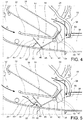
- a mixing flap 40 (visible in Figures 2-8 ) is mounted in the casing 10 and is arranged in the mixing zone 34 at the confluence of the air transmission branch 26 and the air heating branch 28.
- the mixing flap 40 is a butterfly type flap mounted pivotably around an axis 42 arranged near or at the inner partition 32.
- the butterfly flap 40 comprises a first wing 41 associated with the air transmission branch 26 and a second wing 44 associated with a heating branch (28), as well as a wing extension 43 elastically hinged to the first wing 41 according to a hinge axis 45 parallel to the rotation axis 42 of the butterfly flap 40.
- the butterfly flap 40 comprising the first and second wing, is made as a single piece of plastic material.
- the wing extension 43 may be made as a piece of plastic material connected to the first wing 41 by means of a hinge 46 made of elastomeric material.
- the butterfly flap with its wing extension may be made by means of a bi-injection molding process.
- the first wing 41 and the second wing 44 form with each other an angle of less than 180° relative to the rotation axis 42 of the butterfly flap 40.
- a protrusion 47 provided for coupling to an actuating mechanism (not shown) to control the movement of the butterfly flap.
- the way in which the butterfly flap 40 is coupled to an actuating mechanism or actuator is not essential to the present invention.
- first abutment formation 51 Inside the air transmission branch 26 and near the inner partition 32 is arranged a first abutment formation 51, visible in Figures 4-8 .
- This abutment formation 51 may be obtained in the form of a peg placed on a wall of the air transmission branch 26 that interconnects the inner partition 32 and the outer wall 33. The function of this first abutment formation will be clarified hereinafter.
- This abutment formation 52 may also be obtained in the form of a peg arranged on the wall of the air transmission branch 26 that interconnects the inner partition 32 and the outer wall 33. The function of this second abutment formation will be clarified hereinafter.
- the wing extension could be connected to the second wing of the butterfly flap and the abutment formations could be arranged within the air heating branch.
- the butterfly flap 40 is adapted to oscillate between three extreme positions:
- the butterfly flap 40 is in an angular position in which the first wing 41 engages the outer wall 33 of the air transmission branch 26, closing the air transmission branch 26, and the second wing 44 is in abutment against the inner partition 32, obtaining the maximum possible opening for the outflow of the air heating branch 28.
- the air flow that arrives in the mixing zone 34 thus passes exclusively through the air heating branch 28, as indicated by the arrow F 2 in Figure 4 .
- the wing extension 43 is in abutment against the second abutment formation 52 and is held against it by virtue of the elastic force exerted by the elastomeric hinge 46 that connects it to the first wing 41.
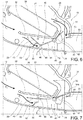
- the butterfly flap 40 has been rotated (clockwise in the figures) to two successive angular positions starting from the extreme hot position of Figure 4 .
- the first wing 41 progressively moves away from the outer wall 33 of the air transmission branch 26, while the second wing 44 progressively approaches the formation 55 obtained near the wall 56 of the air heating branch 28.
- an air flow is also obtained through the air transmission branch 26, indicated at F 3 in Figures 5 and 6 , which mixes in the mixing zone 34 with the air flow F 2 of the air heating branch 28 with different proportions between Figure 5 and Figure 6 .
- the wing extension 43 in abutment against the second abutment formation 52 is pulled by the butterfly flap 40 and rotates progressively with respect to the first wing 41, around the hinge axis 45, towards a resting position in which the wing extension 43 is approximately aligned with the first wing 41 (represented in Figures 3 and 7 ).
- the butterfly flap 40 has been further rotated (clockwise in the figures) into the angular position corresponding to the extreme cold position.
- the first wing 41 has moved further away from the outer wall 33 of the air transmission branch 26.
- the wing extension 43 pulled by the butterfly flap 40, has moved away from the second abutment formation 52 and has been brought into abutment against the first abutment formation 51.
- the butterfly flap 40 starts rotating again with respect to the first wing 41, but with a torque of the elastic force of the hinge 46 oriented in the opposite direction with respect to that which occurred in passing from the position of Figure 4 to the position of Figure 7 .
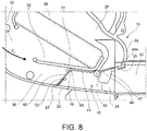
- the butterfly flap 40 has been further rotated (clockwise in the figures) into the angular position corresponding to the extreme closing position.
- the first wing 41 has moved further away from the outer wall 33 of the air transmission branch 26.
- the wing extension 43 pulled by the butterfly flap 40 and in abutment against the first abutment formation 51, has been rotated further until the free end thereof has been brought against the outer wall 33 of the air transmission branch 26 or, more precisely, against a support 57 obtained on this outer wall 33, while the elastomeric hinge 46 has been brought against the inner partition 32.
- the wing extension 43 interrupts the air flow passage of the air transmission branch 26.
- the second wing 44 has continued to maintain its abutment against the formation 55 obtained near the wall 56 of the air heating branch 28, due to the deformability of the flexible lip 44a thereof.
- the change from the position of Figure 7 to the position of Figure 8 may be achieved by rotating the butterfly flap 40 by a few degrees. However, by adequately sizing the position of the first abutment formation 51 and the hinge axis 45, it is possible to obtain a significantly greater rotation of the wing extension 43 with respect to the first wing 41.
Landscapes
- Physics & Mathematics (AREA)
- Thermal Sciences (AREA)
- Engineering & Computer Science (AREA)
- Mechanical Engineering (AREA)
- Air-Conditioning For Vehicles (AREA)
- Lock And Its Accessories (AREA)
- Power-Operated Mechanisms For Wings (AREA)
Claims (6)
- Klimatisierungsvorrichtung für ein Fahrzeug, aufweisend einen Einlasskanal (12) zur Frischluftzufuhr, einen Luftübermittlungsast (26) und einen Lufterwärmungsast (28), die beide von dem Einlasskanal (12) gespeist werden und durch eine Mischzone (34) miteinander in Verbindung stehen, sowie eine Mischeinrichtung, die zum Verteilen eines Luftstroms zwischen dem Luftübermittlungsast (26) und dem Lufterwärmungsast (28) in der Mischzone angeordnet ist, wobei die Mischeinrichtung verstellbar ist zwischen einer Extremheiz-Position, in der die Mischeinrichtung eine Verbindung zwischen dem Luftübermittlungsast (26) und der Mischzone (34) verhindert und den Luftstrom zum Durchströmen des Lufterwärmungsasts (28) zwingt, einer Extremkühl-Position, in der die Mischeinrichtung eine Verbindung zwischen dem Lufterwärmungsast (28) und der Mischzone (34) verhindert und den Luftstrom zum Durchströmen des Luftübermittlungsasts (26) zwingt, und einer Extremverschluss-Position, in der die Mischeinrichtung eine Verbindung zwischen der Mischzone (34) und sowohl dem Luftübermittlungsast (26) als auch dem Lufterwärmungsast (28) verhindert;
wobei
die Mischeinrichtung eine Schmetterlingsklappe (40) aufweist, die schwenkbar um eine in der Mischzone (34) angeordnete Schwenkachse (42) gelagert ist,
wobei die Schmetterlingsklappe einen ersten Flügel (41), der einem von Luftübermittlungsast und Lufterwärmungsast, im folgenden erster Ast (26), zugeordnet ist, und einen zweiten Flügel (44), der dem anderen von Luftübermittlungsast und Lufterwärmungsast, im folgenden zweiter Ast (26), zugeordnet ist, sowie einen Flügelfortsatz (43) aufweist, der an dem ersten Flügel schwenkbar um eine zur Schwenkachse (42) der Schmetterlingsklappe (40) parallele Scharnierachse (45) angelenkt ist, wobei in der Extremverschluss-Position der Flügelfortsatz (43) eine Verbindung zwischen dem ersten Ast (26) und der Mischzone (34) verhindert und der zweite Flügel (44) eine Verbindung zwischen dem zweiten Ast (28) und der Mischzone (34) verhindert,
dadurch gekennzeichnet, dass
der Flügelfortsatz (43) elastisch an den ersten Flügel (41) angelenkt ist; und dass innerhalb des ersten Asts (26) Anschlagsmittel (51, 52) angeordnet sind, die dazu ausgelegt sind, mit dem Flügelfortsatz (43) in Eingriff zu kommen und während dem Verschwenken der Schmetterlingsklappe (40) zu bewirken, dass der Flügelfortsatz (43) relativ zu dem ersten Flügel (41) verschwenkt. - Vorrichtung gemäß Anspruch 1, wobei der erste Ast (26) ein Paar sich gegenüberliegender Wände, im Folgenden erste und zweite Wand (32, 33), aufweist, wobei die Anschlagsmittel eine in der Nähe der ersten Wand (32) angeordnete erste Anschlagsanordnung (51) aufweisen und wobei der Flügelfortsatz (43) in der Extremverschluss-Position mit der ersten Anschlagsanordnung (51) und der zweiten Wand (33) in Eingriff steht.
- Vorrichtung gemäß Anspruch 2, wobei in der Extremverschluss-Position der Flügelfortsatz (43) auch mit der ersten Wand (32) in Eingriff steht.
- Vorrichtung gemäß Anspruch 2 oder 3, wobei die Anschlagsmittel eine in der Nähe der zweiten Wand (33) angeordnete zweite Anschlagsanordnung (52) aufweisen, wobei in einer Position, in der der erste Flügel (41) den ersten Ast (26) verschließt, der Flügelfortsatz (43) an der zweiten Anschlagsanordnung (52) anliegt.
- Vorrichtung gemäß einem der vorangehenden Ansprüche, wobei der Flügelfortsatz (43) durch ein Scharnier (46) aus elastomerem Material mit dem ersten Flügel (41) verbunden ist.
- Vorrichtung gemäß einem der vorangehenden Ansprüche, wobei der erste Flügel (41) und der zweite Flügel (44) miteinander einen Winkel von weniger als 180° bezüglich der Schwenkachse (42) der Schmetterlingsklappe (40) bilden.
Applications Claiming Priority (1)
| Application Number | Priority Date | Filing Date | Title |
|---|---|---|---|
| IT102018000009225A IT201800009225A1 (it) | 2018-10-08 | 2018-10-08 | Dispositivo di climatizzazione per un veicolo comprendente una portella articolata. |
Publications (2)
| Publication Number | Publication Date |
|---|---|
| EP3636470A1 EP3636470A1 (de) | 2020-04-15 |
| EP3636470B1 true EP3636470B1 (de) | 2021-05-19 |
Family
ID=64902232
Family Applications (1)
| Application Number | Title | Priority Date | Filing Date |
|---|---|---|---|
| EP19201379.5A Active EP3636470B1 (de) | 2018-10-08 | 2019-10-04 | Klimaanlage für ein fahrzeug mit einer gelenkklappe |
Country Status (4)
| Country | Link |
|---|---|
| US (1) | US11241938B2 (de) |
| EP (1) | EP3636470B1 (de) |
| ES (1) | ES2885690T3 (de) |
| IT (1) | IT201800009225A1 (de) |
Families Citing this family (1)
| Publication number | Priority date | Publication date | Assignee | Title |
|---|---|---|---|---|
| WO2023198863A1 (en) * | 2022-04-14 | 2023-10-19 | Valeo Systemes Thermiques | Vehicular air conditioner |
Family Cites Families (6)
| Publication number | Priority date | Publication date | Assignee | Title |
|---|---|---|---|---|
| FR2783755B1 (fr) * | 1998-09-30 | 2000-12-15 | Valeo Climatisation | Dispositif de chauffage-ventilation et/ou climatisation avec un volet d'isolement |
| FR2787393B1 (fr) * | 1998-12-22 | 2001-03-30 | Valeo Climatisation | Dispositif de chauffage et/ou climatisation de vehicule automobile a mixage d'air ameliore |
| JP4253960B2 (ja) * | 1999-11-18 | 2009-04-15 | 株式会社デンソー | 車両用空調装置 |
| US7954540B2 (en) * | 2008-12-18 | 2011-06-07 | Delphi Technologies, Inc. | HVAC assembly including temperature mixing valve |
| DE102010052259A1 (de) * | 2010-11-23 | 2012-05-24 | Valeo Klimasysteme Gmbh | Fahrzeugbelüftungssystem |
| US9919576B2 (en) * | 2013-08-22 | 2018-03-20 | Hanon Systems | Air conditioner for vehicle and controlling method thereof |
-
2018
- 2018-10-08 IT IT102018000009225A patent/IT201800009225A1/it unknown
-
2019
- 2019-10-04 ES ES19201379T patent/ES2885690T3/es active Active
- 2019-10-04 EP EP19201379.5A patent/EP3636470B1/de active Active
- 2019-10-07 US US16/595,225 patent/US11241938B2/en active Active
Non-Patent Citations (1)
| Title |
|---|
| None * |
Also Published As
| Publication number | Publication date |
|---|---|
| EP3636470A1 (de) | 2020-04-15 |
| US11241938B2 (en) | 2022-02-08 |
| ES2885690T3 (es) | 2021-12-15 |
| IT201800009225A1 (it) | 2020-04-08 |
| US20200108696A1 (en) | 2020-04-09 |
Similar Documents
| Publication | Publication Date | Title |
|---|---|---|
| US6419006B1 (en) | Motor vehicle heating and/or air conditioning device with improved air mixing | |
| US4802405A (en) | Automotive air-conditioner | |
| KR20080026056A (ko) | 특히 자동차 공기 조화 시스템용 공기 덕트 하우징 내의분배 플랩과 대응하는 분배 플랩을 조절하기 위한 방법 | |
| US10081225B2 (en) | Vehicle air conditioner slotted mode cam | |
| US9616729B2 (en) | Vehicular air conditioner | |
| EP0058416B1 (de) | Klimatisierungssystem | |
| US4267880A (en) | Air distribution device | |
| US9931908B2 (en) | HVAC air inlet with blend mode and fresh-restricted mode | |
| CN101557952B (zh) | 带有空气混合和分配阀的汽车取暖和/或空调设备 | |
| AU752056B2 (en) | Air mix damper device and vehicle air conditioner | |
| US6439296B1 (en) | Heating or air-conditioning system for a vehicle occupant compartment | |
| KR102189136B1 (ko) | 차량용 공기조화장치 | |
| EP3636470B1 (de) | Klimaanlage für ein fahrzeug mit einer gelenkklappe | |
| KR101758722B1 (ko) | 차량용 공조장치 | |
| US20180010678A1 (en) | Cam-operated device for controlling at least one component | |
| US5070770A (en) | Simultaneous temperature and mode selector for heating and cooling | |
| US20090209189A1 (en) | Air-Conditioning System for Vehicles | |
| US5025711A (en) | Simultaneous temperature and mode selector for heating and cooling | |
| KR20130050456A (ko) | 차량용 공조장치 | |
| US6319111B1 (en) | Heating and/or air conditioning device for a vehicle passenger compartment with improved air mixing | |
| CN101730630A (zh) | 空气分配和/或空气混合装置 | |
| KR102470404B1 (ko) | 차량용 공조장치 | |
| EP4470808B1 (de) | Heiz- und/oder klimaanlage für ein kraftfahrzeug | |
| CN113165478A (zh) | 用于机动车的送风设备 | |
| US20080256965A1 (en) | Heating And/Or Air Conditioning Unit For Vehicles |
Legal Events
| Date | Code | Title | Description |
|---|---|---|---|
| PUAI | Public reference made under article 153(3) epc to a published international application that has entered the european phase |
Free format text: ORIGINAL CODE: 0009012 |
|
| STAA | Information on the status of an ep patent application or granted ep patent |
Free format text: STATUS: THE APPLICATION HAS BEEN PUBLISHED |
|
| AK | Designated contracting states |
Kind code of ref document: A1 Designated state(s): AL AT BE BG CH CY CZ DE DK EE ES FI FR GB GR HR HU IE IS IT LI LT LU LV MC MK MT NL NO PL PT RO RS SE SI SK SM TR |
|
| AX | Request for extension of the european patent |
Extension state: BA ME |
|
| STAA | Information on the status of an ep patent application or granted ep patent |
Free format text: STATUS: REQUEST FOR EXAMINATION WAS MADE |
|
| 17P | Request for examination filed |
Effective date: 20201005 |
|
| RBV | Designated contracting states (corrected) |
Designated state(s): AL AT BE BG CH CY CZ DE DK EE ES FI FR GB GR HR HU IE IS IT LI LT LU LV MC MK MT NL NO PL PT RO RS SE SI SK SM TR |
|
| GRAP | Despatch of communication of intention to grant a patent |
Free format text: ORIGINAL CODE: EPIDOSNIGR1 |
|
| STAA | Information on the status of an ep patent application or granted ep patent |
Free format text: STATUS: GRANT OF PATENT IS INTENDED |
|
| RIC1 | Information provided on ipc code assigned before grant |
Ipc: B60H 1/00 20060101AFI20201119BHEP |
|
| INTG | Intention to grant announced |
Effective date: 20201223 |
|
| GRAS | Grant fee paid |
Free format text: ORIGINAL CODE: EPIDOSNIGR3 |
|
| GRAA | (expected) grant |
Free format text: ORIGINAL CODE: 0009210 |
|
| STAA | Information on the status of an ep patent application or granted ep patent |
Free format text: STATUS: THE PATENT HAS BEEN GRANTED |
|
| AK | Designated contracting states |
Kind code of ref document: B1 Designated state(s): AL AT BE BG CH CY CZ DE DK EE ES FI FR GB GR HR HU IE IS IT LI LT LU LV MC MK MT NL NO PL PT RO RS SE SI SK SM TR |
|
| REG | Reference to a national code |
Ref country code: GB Ref legal event code: FG4D |
|
| REG | Reference to a national code |
Ref country code: CH Ref legal event code: EP |
|
| REG | Reference to a national code |
Ref country code: DE Ref legal event code: R096 Ref document number: 602019004711 Country of ref document: DE |
|
| REG | Reference to a national code |
Ref country code: AT Ref legal event code: REF Ref document number: 1393646 Country of ref document: AT Kind code of ref document: T Effective date: 20210615 |
|
| REG | Reference to a national code |
Ref country code: IE Ref legal event code: FG4D |
|
| REG | Reference to a national code |
Ref country code: LT Ref legal event code: MG9D |
|
| REG | Reference to a national code |
Ref country code: AT Ref legal event code: MK05 Ref document number: 1393646 Country of ref document: AT Kind code of ref document: T Effective date: 20210519 |
|
| REG | Reference to a national code |
Ref country code: NL Ref legal event code: MP Effective date: 20210519 |
|
| PG25 | Lapsed in a contracting state [announced via postgrant information from national office to epo] |
Ref country code: FI Free format text: LAPSE BECAUSE OF FAILURE TO SUBMIT A TRANSLATION OF THE DESCRIPTION OR TO PAY THE FEE WITHIN THE PRESCRIBED TIME-LIMIT Effective date: 20210519 Ref country code: HR Free format text: LAPSE BECAUSE OF FAILURE TO SUBMIT A TRANSLATION OF THE DESCRIPTION OR TO PAY THE FEE WITHIN THE PRESCRIBED TIME-LIMIT Effective date: 20210519 Ref country code: LT Free format text: LAPSE BECAUSE OF FAILURE TO SUBMIT A TRANSLATION OF THE DESCRIPTION OR TO PAY THE FEE WITHIN THE PRESCRIBED TIME-LIMIT Effective date: 20210519 Ref country code: BG Free format text: LAPSE BECAUSE OF FAILURE TO SUBMIT A TRANSLATION OF THE DESCRIPTION OR TO PAY THE FEE WITHIN THE PRESCRIBED TIME-LIMIT Effective date: 20210819 Ref country code: AT Free format text: LAPSE BECAUSE OF FAILURE TO SUBMIT A TRANSLATION OF THE DESCRIPTION OR TO PAY THE FEE WITHIN THE PRESCRIBED TIME-LIMIT Effective date: 20210519 |
|
| PG25 | Lapsed in a contracting state [announced via postgrant information from national office to epo] |
Ref country code: GR Free format text: LAPSE BECAUSE OF FAILURE TO SUBMIT A TRANSLATION OF THE DESCRIPTION OR TO PAY THE FEE WITHIN THE PRESCRIBED TIME-LIMIT Effective date: 20210820 Ref country code: IS Free format text: LAPSE BECAUSE OF FAILURE TO SUBMIT A TRANSLATION OF THE DESCRIPTION OR TO PAY THE FEE WITHIN THE PRESCRIBED TIME-LIMIT Effective date: 20210919 Ref country code: PL Free format text: LAPSE BECAUSE OF FAILURE TO SUBMIT A TRANSLATION OF THE DESCRIPTION OR TO PAY THE FEE WITHIN THE PRESCRIBED TIME-LIMIT Effective date: 20210519 Ref country code: NO Free format text: LAPSE BECAUSE OF FAILURE TO SUBMIT A TRANSLATION OF THE DESCRIPTION OR TO PAY THE FEE WITHIN THE PRESCRIBED TIME-LIMIT Effective date: 20210819 Ref country code: LV Free format text: LAPSE BECAUSE OF FAILURE TO SUBMIT A TRANSLATION OF THE DESCRIPTION OR TO PAY THE FEE WITHIN THE PRESCRIBED TIME-LIMIT Effective date: 20210519 Ref country code: RS Free format text: LAPSE BECAUSE OF FAILURE TO SUBMIT A TRANSLATION OF THE DESCRIPTION OR TO PAY THE FEE WITHIN THE PRESCRIBED TIME-LIMIT Effective date: 20210519 Ref country code: PT Free format text: LAPSE BECAUSE OF FAILURE TO SUBMIT A TRANSLATION OF THE DESCRIPTION OR TO PAY THE FEE WITHIN THE PRESCRIBED TIME-LIMIT Effective date: 20210920 Ref country code: SE Free format text: LAPSE BECAUSE OF FAILURE TO SUBMIT A TRANSLATION OF THE DESCRIPTION OR TO PAY THE FEE WITHIN THE PRESCRIBED TIME-LIMIT Effective date: 20210519 |
|
| REG | Reference to a national code |
Ref country code: ES Ref legal event code: FG2A Ref document number: 2885690 Country of ref document: ES Kind code of ref document: T3 Effective date: 20211215 |
|
| PG25 | Lapsed in a contracting state [announced via postgrant information from national office to epo] |
Ref country code: NL Free format text: LAPSE BECAUSE OF FAILURE TO SUBMIT A TRANSLATION OF THE DESCRIPTION OR TO PAY THE FEE WITHIN THE PRESCRIBED TIME-LIMIT Effective date: 20210519 |
|
| PG25 | Lapsed in a contracting state [announced via postgrant information from national office to epo] |
Ref country code: SK Free format text: LAPSE BECAUSE OF FAILURE TO SUBMIT A TRANSLATION OF THE DESCRIPTION OR TO PAY THE FEE WITHIN THE PRESCRIBED TIME-LIMIT Effective date: 20210519 Ref country code: EE Free format text: LAPSE BECAUSE OF FAILURE TO SUBMIT A TRANSLATION OF THE DESCRIPTION OR TO PAY THE FEE WITHIN THE PRESCRIBED TIME-LIMIT Effective date: 20210519 Ref country code: CZ Free format text: LAPSE BECAUSE OF FAILURE TO SUBMIT A TRANSLATION OF THE DESCRIPTION OR TO PAY THE FEE WITHIN THE PRESCRIBED TIME-LIMIT Effective date: 20210519 Ref country code: DK Free format text: LAPSE BECAUSE OF FAILURE TO SUBMIT A TRANSLATION OF THE DESCRIPTION OR TO PAY THE FEE WITHIN THE PRESCRIBED TIME-LIMIT Effective date: 20210519 Ref country code: RO Free format text: LAPSE BECAUSE OF FAILURE TO SUBMIT A TRANSLATION OF THE DESCRIPTION OR TO PAY THE FEE WITHIN THE PRESCRIBED TIME-LIMIT Effective date: 20210519 Ref country code: SM Free format text: LAPSE BECAUSE OF FAILURE TO SUBMIT A TRANSLATION OF THE DESCRIPTION OR TO PAY THE FEE WITHIN THE PRESCRIBED TIME-LIMIT Effective date: 20210519 |
|
| REG | Reference to a national code |
Ref country code: DE Ref legal event code: R097 Ref document number: 602019004711 Country of ref document: DE |
|
| PLBE | No opposition filed within time limit |
Free format text: ORIGINAL CODE: 0009261 |
|
| STAA | Information on the status of an ep patent application or granted ep patent |
Free format text: STATUS: NO OPPOSITION FILED WITHIN TIME LIMIT |
|
| 26N | No opposition filed |
Effective date: 20220222 |
|
| PG25 | Lapsed in a contracting state [announced via postgrant information from national office to epo] |
Ref country code: IS Free format text: LAPSE BECAUSE OF FAILURE TO SUBMIT A TRANSLATION OF THE DESCRIPTION OR TO PAY THE FEE WITHIN THE PRESCRIBED TIME-LIMIT Effective date: 20210919 Ref country code: AL Free format text: LAPSE BECAUSE OF FAILURE TO SUBMIT A TRANSLATION OF THE DESCRIPTION OR TO PAY THE FEE WITHIN THE PRESCRIBED TIME-LIMIT Effective date: 20210519 |
|
| REG | Reference to a national code |
Ref country code: BE Ref legal event code: MM Effective date: 20211031 |
|
| PG25 | Lapsed in a contracting state [announced via postgrant information from national office to epo] |
Ref country code: MC Free format text: LAPSE BECAUSE OF FAILURE TO SUBMIT A TRANSLATION OF THE DESCRIPTION OR TO PAY THE FEE WITHIN THE PRESCRIBED TIME-LIMIT Effective date: 20210519 |
|
| PG25 | Lapsed in a contracting state [announced via postgrant information from national office to epo] |
Ref country code: LU Free format text: LAPSE BECAUSE OF NON-PAYMENT OF DUE FEES Effective date: 20211004 Ref country code: IT Free format text: LAPSE BECAUSE OF FAILURE TO SUBMIT A TRANSLATION OF THE DESCRIPTION OR TO PAY THE FEE WITHIN THE PRESCRIBED TIME-LIMIT Effective date: 20210519 Ref country code: BE Free format text: LAPSE BECAUSE OF NON-PAYMENT OF DUE FEES Effective date: 20211031 |
|
| PG25 | Lapsed in a contracting state [announced via postgrant information from national office to epo] |
Ref country code: IE Free format text: LAPSE BECAUSE OF NON-PAYMENT OF DUE FEES Effective date: 20211004 |
|
| REG | Reference to a national code |
Ref country code: CH Ref legal event code: PL |
|
| PG25 | Lapsed in a contracting state [announced via postgrant information from national office to epo] |
Ref country code: CY Free format text: LAPSE BECAUSE OF FAILURE TO SUBMIT A TRANSLATION OF THE DESCRIPTION OR TO PAY THE FEE WITHIN THE PRESCRIBED TIME-LIMIT Effective date: 20210519 |
|
| PG25 | Lapsed in a contracting state [announced via postgrant information from national office to epo] |
Ref country code: LI Free format text: LAPSE BECAUSE OF NON-PAYMENT OF DUE FEES Effective date: 20221031 Ref country code: HU Free format text: LAPSE BECAUSE OF FAILURE TO SUBMIT A TRANSLATION OF THE DESCRIPTION OR TO PAY THE FEE WITHIN THE PRESCRIBED TIME-LIMIT; INVALID AB INITIO Effective date: 20191004 Ref country code: CH Free format text: LAPSE BECAUSE OF NON-PAYMENT OF DUE FEES Effective date: 20221031 |
|
| PG25 | Lapsed in a contracting state [announced via postgrant information from national office to epo] |
Ref country code: MK Free format text: LAPSE BECAUSE OF FAILURE TO SUBMIT A TRANSLATION OF THE DESCRIPTION OR TO PAY THE FEE WITHIN THE PRESCRIBED TIME-LIMIT Effective date: 20210519 |
|
| GBPC | Gb: european patent ceased through non-payment of renewal fee |
Effective date: 20231004 |
|
| PG25 | Lapsed in a contracting state [announced via postgrant information from national office to epo] |
Ref country code: GB Free format text: LAPSE BECAUSE OF NON-PAYMENT OF DUE FEES Effective date: 20231004 |
|
| PG25 | Lapsed in a contracting state [announced via postgrant information from national office to epo] |
Ref country code: GB Free format text: LAPSE BECAUSE OF NON-PAYMENT OF DUE FEES Effective date: 20231004 |
|
| PG25 | Lapsed in a contracting state [announced via postgrant information from national office to epo] |
Ref country code: MT Free format text: LAPSE BECAUSE OF FAILURE TO SUBMIT A TRANSLATION OF THE DESCRIPTION OR TO PAY THE FEE WITHIN THE PRESCRIBED TIME-LIMIT Effective date: 20210519 |
|
| PGFP | Annual fee paid to national office [announced via postgrant information from national office to epo] |
Ref country code: FR Payment date: 20250930 Year of fee payment: 7 |
|
| PG25 | Lapsed in a contracting state [announced via postgrant information from national office to epo] |
Ref country code: TR Free format text: LAPSE BECAUSE OF FAILURE TO SUBMIT A TRANSLATION OF THE DESCRIPTION OR TO PAY THE FEE WITHIN THE PRESCRIBED TIME-LIMIT Effective date: 20210519 |
|
| PGFP | Annual fee paid to national office [announced via postgrant information from national office to epo] |
Ref country code: DE Payment date: 20251027 Year of fee payment: 7 |
|
| PGFP | Annual fee paid to national office [announced via postgrant information from national office to epo] |
Ref country code: ES Payment date: 20251103 Year of fee payment: 7 |