EP3636334A1 - Spray pipe and desulfurization device provided with same - Google Patents
Spray pipe and desulfurization device provided with same Download PDFInfo
- Publication number
- EP3636334A1 EP3636334A1 EP17912893.9A EP17912893A EP3636334A1 EP 3636334 A1 EP3636334 A1 EP 3636334A1 EP 17912893 A EP17912893 A EP 17912893A EP 3636334 A1 EP3636334 A1 EP 3636334A1
- Authority
- EP
- European Patent Office
- Prior art keywords
- pipe
- spray pipe
- disposed
- end portion
- support
- Prior art date
- Legal status (The legal status is an assumption and is not a legal conclusion. Google has not performed a legal analysis and makes no representation as to the accuracy of the status listed.)
- Withdrawn
Links
Images





Classifications
-
- B—PERFORMING OPERATIONS; TRANSPORTING
- B01—PHYSICAL OR CHEMICAL PROCESSES OR APPARATUS IN GENERAL
- B01D—SEPARATION
- B01D53/00—Separation of gases or vapours; Recovering vapours of volatile solvents from gases; Chemical or biological purification of waste gases, e.g. engine exhaust gases, smoke, fumes, flue gases, aerosols
- B01D53/34—Chemical or biological purification of waste gases
- B01D53/46—Removing components of defined structure
- B01D53/48—Sulfur compounds
- B01D53/50—Sulfur oxides
- B01D53/501—Sulfur oxides by treating the gases with a solution or a suspension of an alkali or earth-alkali or ammonium compound
- B01D53/504—Sulfur oxides by treating the gases with a solution or a suspension of an alkali or earth-alkali or ammonium compound characterised by a specific device
-
- F—MECHANICAL ENGINEERING; LIGHTING; HEATING; WEAPONS; BLASTING
- F23—COMBUSTION APPARATUS; COMBUSTION PROCESSES
- F23J—REMOVAL OR TREATMENT OF COMBUSTION PRODUCTS OR COMBUSTION RESIDUES; FLUES
- F23J15/00—Arrangements of devices for treating smoke or fumes
- F23J15/02—Arrangements of devices for treating smoke or fumes of purifiers, e.g. for removing noxious material
- F23J15/04—Arrangements of devices for treating smoke or fumes of purifiers, e.g. for removing noxious material using washing fluids
-
- B—PERFORMING OPERATIONS; TRANSPORTING
- B01—PHYSICAL OR CHEMICAL PROCESSES OR APPARATUS IN GENERAL
- B01D—SEPARATION
- B01D53/00—Separation of gases or vapours; Recovering vapours of volatile solvents from gases; Chemical or biological purification of waste gases, e.g. engine exhaust gases, smoke, fumes, flue gases, aerosols
- B01D53/14—Separation of gases or vapours; Recovering vapours of volatile solvents from gases; Chemical or biological purification of waste gases, e.g. engine exhaust gases, smoke, fumes, flue gases, aerosols by absorption
- B01D53/1456—Removing acid components
-
- B—PERFORMING OPERATIONS; TRANSPORTING
- B01—PHYSICAL OR CHEMICAL PROCESSES OR APPARATUS IN GENERAL
- B01D—SEPARATION
- B01D53/00—Separation of gases or vapours; Recovering vapours of volatile solvents from gases; Chemical or biological purification of waste gases, e.g. engine exhaust gases, smoke, fumes, flue gases, aerosols
- B01D53/14—Separation of gases or vapours; Recovering vapours of volatile solvents from gases; Chemical or biological purification of waste gases, e.g. engine exhaust gases, smoke, fumes, flue gases, aerosols by absorption
- B01D53/18—Absorbing units; Liquid distributors therefor
- B01D53/185—Liquid distributors
-
- B—PERFORMING OPERATIONS; TRANSPORTING
- B01—PHYSICAL OR CHEMICAL PROCESSES OR APPARATUS IN GENERAL
- B01D—SEPARATION
- B01D53/00—Separation of gases or vapours; Recovering vapours of volatile solvents from gases; Chemical or biological purification of waste gases, e.g. engine exhaust gases, smoke, fumes, flue gases, aerosols
- B01D53/34—Chemical or biological purification of waste gases
- B01D53/46—Removing components of defined structure
- B01D53/48—Sulfur compounds
- B01D53/50—Sulfur oxides
- B01D53/501—Sulfur oxides by treating the gases with a solution or a suspension of an alkali or earth-alkali or ammonium compound
- B01D53/502—Sulfur oxides by treating the gases with a solution or a suspension of an alkali or earth-alkali or ammonium compound characterised by a specific solution or suspension
-
- B—PERFORMING OPERATIONS; TRANSPORTING
- B01—PHYSICAL OR CHEMICAL PROCESSES OR APPARATUS IN GENERAL
- B01D—SEPARATION
- B01D53/00—Separation of gases or vapours; Recovering vapours of volatile solvents from gases; Chemical or biological purification of waste gases, e.g. engine exhaust gases, smoke, fumes, flue gases, aerosols
- B01D53/34—Chemical or biological purification of waste gases
- B01D53/74—General processes for purification of waste gases; Apparatus or devices specially adapted therefor
- B01D53/77—Liquid phase processes
- B01D53/78—Liquid phase processes with gas-liquid contact
-
- B—PERFORMING OPERATIONS; TRANSPORTING
- B01—PHYSICAL OR CHEMICAL PROCESSES OR APPARATUS IN GENERAL
- B01D—SEPARATION
- B01D53/00—Separation of gases or vapours; Recovering vapours of volatile solvents from gases; Chemical or biological purification of waste gases, e.g. engine exhaust gases, smoke, fumes, flue gases, aerosols
- B01D53/34—Chemical or biological purification of waste gases
- B01D53/74—General processes for purification of waste gases; Apparatus or devices specially adapted therefor
- B01D53/77—Liquid phase processes
- B01D53/79—Injecting reactants
-
- B—PERFORMING OPERATIONS; TRANSPORTING
- B05—SPRAYING OR ATOMISING IN GENERAL; APPLYING FLUENT MATERIALS TO SURFACES, IN GENERAL
- B05B—SPRAYING APPARATUS; ATOMISING APPARATUS; NOZZLES
- B05B1/00—Nozzles, spray heads or other outlets, with or without auxiliary devices such as valves, heating means
- B05B1/14—Nozzles, spray heads or other outlets, with or without auxiliary devices such as valves, heating means with multiple outlet openings; with strainers in or outside the outlet opening
- B05B1/20—Perforated pipes or troughs, e.g. spray booms; Outlet elements therefor
-
- B—PERFORMING OPERATIONS; TRANSPORTING
- B05—SPRAYING OR ATOMISING IN GENERAL; APPLYING FLUENT MATERIALS TO SURFACES, IN GENERAL
- B05B—SPRAYING APPARATUS; ATOMISING APPARATUS; NOZZLES
- B05B15/00—Details of spraying plant or spraying apparatus not otherwise provided for; Accessories
- B05B15/60—Arrangements for mounting, supporting or holding spraying apparatus
-
- B—PERFORMING OPERATIONS; TRANSPORTING
- B01—PHYSICAL OR CHEMICAL PROCESSES OR APPARATUS IN GENERAL
- B01D—SEPARATION
- B01D2251/00—Reactants
- B01D2251/40—Alkaline earth metal or magnesium compounds
- B01D2251/404—Alkaline earth metal or magnesium compounds of calcium
-
- B—PERFORMING OPERATIONS; TRANSPORTING
- B05—SPRAYING OR ATOMISING IN GENERAL; APPLYING FLUENT MATERIALS TO SURFACES, IN GENERAL
- B05B—SPRAYING APPARATUS; ATOMISING APPARATUS; NOZZLES
- B05B9/00—Spraying apparatus for discharge of liquids or other fluent material, without essentially mixing with gas or vapour
- B05B9/03—Spraying apparatus for discharge of liquids or other fluent material, without essentially mixing with gas or vapour characterised by means for supplying liquid or other fluent material
- B05B9/04—Spraying apparatus for discharge of liquids or other fluent material, without essentially mixing with gas or vapour characterised by means for supplying liquid or other fluent material with pressurised or compressible container; with pump
- B05B9/0403—Spraying apparatus for discharge of liquids or other fluent material, without essentially mixing with gas or vapour characterised by means for supplying liquid or other fluent material with pressurised or compressible container; with pump with pumps for liquids or other fluent material
- B05B9/0423—Spraying apparatus for discharge of liquids or other fluent material, without essentially mixing with gas or vapour characterised by means for supplying liquid or other fluent material with pressurised or compressible container; with pump with pumps for liquids or other fluent material for supplying liquid or other fluent material to several spraying apparatus
-
- F—MECHANICAL ENGINEERING; LIGHTING; HEATING; WEAPONS; BLASTING
- F23—COMBUSTION APPARATUS; COMBUSTION PROCESSES
- F23J—REMOVAL OR TREATMENT OF COMBUSTION PRODUCTS OR COMBUSTION RESIDUES; FLUES
- F23J2215/00—Preventing emissions
- F23J2215/20—Sulfur; Compounds thereof
-
- F—MECHANICAL ENGINEERING; LIGHTING; HEATING; WEAPONS; BLASTING
- F23—COMBUSTION APPARATUS; COMBUSTION PROCESSES
- F23J—REMOVAL OR TREATMENT OF COMBUSTION PRODUCTS OR COMBUSTION RESIDUES; FLUES
- F23J2217/00—Intercepting solids
- F23J2217/50—Intercepting solids by cleaning fluids (washers or scrubbers)
Definitions
- the present invention relates to a spray pipe and a desulfurization apparatus provided with the spray pipe.
- An exhaust gas system such as a boiler, installed in a power plant or the like, is provided with a desulfurization apparatus which removes sulfur oxides from exhaust gas.
- a desulfurization apparatus which removes sulfur oxides from exhaust gas.
- PTL 1 and PTL 2 disclose a liquid column type desulfurization apparatus where an absorbing liquid is injected upward from a plurality of nozzles, mounted on a branch pipe (header) installed horizontally, so as to remove sulfur oxides in a combustion exhaust gas via a chemical reaction between the combustion exhaust gas and the absorbing liquid.
- a downward reaction force is applied to the branch pipe as the branch pipe injects an absorbing liquid upward. Further, a downward impact force is also applied to the branch pipe when the absorbing liquid, which the branch pipe injects upward, falls and comes into contact with the branch pipe.
- nozzles 6 which inject an absorbing liquid are mounted on a branch pipe 5, and the branch pipe 5 is supported by a plurality of support rods 9.
- the support rods 9 are arranged below the branch pipe so as to be orthogonal to the branch pipe 5, and the support rods 9 are separated at a distance from each other.
- the branch pipe 5 and each support rod 9 have a circular outer shape, and come into contact with each other at a position where the branch pipe 5 and each support rod 9 intersect with each other. Accordingly, there is a possibility of the branch pipe being damaged (including generation of cracks and local deformation) by local force acting at respective positions coming into contact with the support rods.
- a branch pipe (header) 14, 15 is supported in a state of being restrained by U-shaped support straps 34 each having an upper end connected to a beam 32. Accordingly, there is a possibility of the branch pipe 14, 15 being damaged by local force acting at a position coming into contact with the support strap 34. Such a problem caused by local force acting on the branch pipe becomes particularly obvious when the shape of an inner peripheral surface of the support strap 34 and the shape of an outer peripheral surface of the branch pipe 14, 15 do not agree with each other. Further, such a problem may occur not only immediately after the branch pipe 14, 15 is restrained by the support strap 34 but also after a long-term use due to fatigue breakage caused by vibrations during operation of the desulfurization apparatus.
- the present invention has been made under such circumstances, and an object of the present invention is to provide a spray pipe and a desulfurization apparatus provided with the spray pipe which can reduce the problem where a reaction force and an impact force are applied to the spray pipe as the spray pipe injects an absorbing liquid upward thus damaging the spray pipe.
- the present invention adopts the following solutions.
- a spray pipe is disposed along a horizontal direction in an absorption tower formed extending along a vertical direction to form a passage for exhaust gas
- the spray pipe includes: a pipe portion having a cylindrical shape, and configured to extend along an axis in the horizontal direction, a distal end portion of the pipe portion being closed; a plurality of nozzle portions configured to guide an absorbing liquid, flowing through the pipe portion in the horizontal direction, upward in a vertical direction, the plurality of nozzle portions being arranged at a plurality of positions on an upper end portion of the pipe portion in the vertical direction; and a leg portion disposed on a lower end portion of the pipe portion in the vertical direction, and having a first surface along the horizontal direction, wherein the leg portion is disposed in a state where the first surface is made to oppositely face a second surface of a support portion installed on the absorption tower, the second surface extending along the horizontal direction.
- the leg portion having the first surface along the horizontal direction is disposed on the lower end portion of the pipe portion in the vertical direction.
- the leg portion is disposed in a state where the first surface is made to oppositely face the second surface of the support portion installed on the absorption tower. Further, a reaction force and an impact force are applied to the spray pipe as the spray pipe injects an absorbing liquid upward, and the reaction force and the impact force are transmitted from the first surface to the second surface. Accordingly, it is possible to prevent a reaction force and an impact force from being locally applied to the spray pipe thus reducing the problem of damaging the spray pipe.
- the leg portion may be arranged at a plurality of positions including the distal end portion of the pipe portion.
- the load of the spray pipe can be transmitted from the leg portion to the support portion of the desulfurization apparatus also at portions ranging from the intermediate portion to the distal end portion. Accordingly, compared to the case where a load of the spray pipe is not supported by the intermediate portion, it is possible to reduce the problem of the spray pipe being deflected by its own weight.
- the pipe portion may be made of fiber-reinforced plastic.
- a length of the pipe portion along the axis from a proximal end portion to the distal end portion may be set to 3 m or more and 15 m or less, and an outer diameter of the pipe portion may be set to 200 mm or more and 400 mm or less.
- a desulfurization apparatus includes: an absorption tower formed extending along a vertical direction to form a passage for exhaust gas; a spray pipe disposed in the absorption tower along a horizontal direction; a support portion installed on the absorption tower so as to support the spray pipe; and a fastening portion configured to fasten the spray pipe and the support portion to each other, wherein the spray pipe includes: a pipe portion having a cylindrical shape, and configured to extend along an axis in the horizontal direction, a distal end portion of the pipe portion being closed; a plurality of nozzle portions configured to guide an absorbing liquid, flowing through the pipe portion in the horizontal direction, upward in the vertical direction, the plurality of nozzle portions being arranged at a plurality of positions on an upper end portion of the pipe portion in the vertical direction; and a leg portion disposed on a lower end portion of the pipe portion in the vertical direction, and having a first surface along the horizontal direction, wherein the support portion has a second surface along the horizontal direction, and the spray pipe is fast
- the leg portion having the first surface along the horizontal direction is disposed on the lower end portion of the pipe portion of the spray pipe in the vertical direction. Further, the leg portion is disposed in a state where the first surface is made to oppositely face the second surface of the support portion installed on the absorption tower. Further, a reaction force and an impact force are applied to the spray pipe as the spray pipe injects the absorbing liquid upward, and the reaction force and the impact force are transmitted from the first surface to the second surface. Accordingly, it is possible to prevent a reaction force and an impact force from being locally applied to the spray pipe thus reducing the problem of damaging the spray pipe. Further, the spray pipe and the support portion are fastened to each other by the fastening portion and hence, even when a reaction force and an impact force are applied to the spray pipe, a state is maintained where the spray pipe is supported by the support portion.
- the desulfurization apparatus further includes a plate-like member disposed between the first surface and the second surface, the fastening portion includes a fastening bolt and a fastening nut fastened to the fastening bolt, the plate-like member has a cut-away portion which allows insertion of the fastening bolt in a state where the plate-like member is disposed between the first surface and the second surface, and the plate-like member is disposed in a state where the cut-away portion is opened toward the distal end portion of the pipe portion.
- the spray pipe To make the injection direction of an absorbing liquid injected from the spray pipe agrees with the vertical direction, it is necessary to accurately dispose the spray pipe along the horizontal plane.
- the spray pipe In disposing the spray pipe, by disposing the plate-like member having an appropriate thickness between the leg portion and the support portion, the spray pipe can be accurately disposed along the horizontal plane.
- the spray pipe thermally elongates along the axis due to heating by exhaust gas.
- a force toward the closed distal end portion of the pipe portion is applied from the leg portion to the plate-like member disposed in contact with the leg portion.
- the plate-like member is disposed in a state where the cut-away portion opens toward the distal end portion of the pipe portion. That is, the cut-away portion of the plate-like member does not open toward the proximal end portion side of the pipe portion. Accordingly, even when a force toward the distal end portion is applied to the plate-like member from the leg portion, the plate-like member comes into contact with the fastening bolt and hence, there is no possibility of the plate-like member moving toward the distal end portion. Accordingly, it is possible to prevent the problem that the plate-like member moves toward the distal end portion thus escaping from the support portion.
- an insertion hole into which the fastening bolt is inserted may be formed in the first surface of the leg portion, and a length of the insertion hole in a direction along the axis may be set longer than a length of the insertion hole in a direction orthogonal to the axis.
- the spray pipe thermally elongates along the axis due to heating by exhaust gas.
- the leg portion mounted on the spray pipe moves toward the closed distal end portion of the pipe portion.
- a length of the insertion hole in the direction along the axis is set longer. Therefore, it is possible to reduce the problem that the insertion hole comes into contact with the fastening bolt when the leg portion moves due to thermal elongation.
- the pipe portion may be disposed so as to avoid contact with an inner peripheral surface of the absorption tower in a state where the pipe portion is heated by exhaust gas.
- a distal end portion of the pipe portion is preferably disposed with a gap of 10 mm or more and 100 mm or less formed between the distal end portion and the inner wall surface of the absorption tower in a state where the pipe portion is not heated by exhaust gas.
- a spray pipe and a desulfurization apparatus provided with the spray pipe which can reduce the problem where a reaction force and an impact force are applied to the spray pipe as the spray pipe injects an absorbing liquid upward thus damaging the spray pipe.
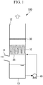
- the desulfurization apparatus 100 of this embodiment includes: an absorption tower 10; spray pipes 20; a demister 30; and a circulation pump 40.
- the absorption tower 10 is a cylindrical casing formed extending in the vertical direction to form a passage for exhaust gas. Exhaust gas containing sulfur oxides is introduced into the absorption tower 10 from an exhaust gas introduction portion 11 formed on a side surface of the absorption tower 10, and the absorption tower 10 guides the exhaust gas upward in the vertical direction. Further, the absorption tower 10 discharges the exhaust gas from an exhaust gas discharge portion 12 formed on the upper side of the absorption tower 10 in the vertical direction.
- the spray pipes 20 are cylindrical members arranged in the inside of the absorption tower 10 along the horizontal direction. As shown in Fig. 1 , the spray pipes 20 inject an absorbing liquid upward in the vertical direction thus causing exhaust gas introduced from the exhaust gas introduction portion 11 and the absorbing liquid to be brought into gas-liquid contact with each other.
- the absorbing liquid is a liquid containing lime so that sulfur oxides contained in the exhaust gas is removed by the lime-gypsum method.
- the absorbing liquid injected from the spray pipes 20 accumulates at a bottom portion 13 of the absorption tower 10. The absorbing liquid accumulated at the bottom portion 13 is supplied to the spray pipes 20 by the circulation pump 40.
- the demister 30 is a folded-plate-shaped demister, for example.
- the demister 30 removes a mist of absorbing liquid generated in the inside of the absorption tower 10 via physical impact.
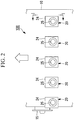
- Fig. 2 is a side view of the spray pipes 20 and a portion around the spray pipes 20 of the desulfurization apparatus 100 shown in Fig. 1 .
- the plurality of spray pipes 20 are inserted into the inside of the absorption tower 10 from the outside of the absorption tower 10.
- five spray pipes 20 are arranged at a predetermined position in the vertical direction, and are arranged at equal intervals in the horizontal direction.
- the number of spray pipes 20 which the desulfurization apparatus 100 includes may be set to a desired number other than five depending on a size or the like of the absorption tower 10.
- the spray pipes 20 may be arranged such that a plurality of spray pipes 20 are arranged on each of a plurality of stages at different positions in the vertical direction.
- a mounting flange 24 and a supply port 25 are formed on each spray pipe 20.
- the mounting flange 24 is a member for mounting the spray pipe 20 on an opening portion 14 formed on the absorption tower 10.
- the mounting flange 24 is mounted on the opening portion 14 of the absorption tower 10 by a plurality of fasteners (not shown in the drawing) (see Fig. 4 ).
- the access hatch 15 can be also used when a maintenance component or the like is brought to the inside from the outside of the absorption tower 10 or when a used component or the like is carried out to the outside from the inside of the absorption tower 10.
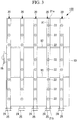
- Fig. 3 is a plan view of the five spray pipes 20 shown in Fig. 2 as viewed from above.
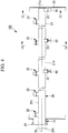
- Fig. 4 is a view of the spray pipe 20 and a portion around the spray pipe 20 of the desulfurization apparatus 100 taken along arrow I-I shown in Fig. 2 .
- each spray pipe 20 includes a pipe portion 21, a plurality of nozzle portions 22, and a plurality of leg portions 23.
- the pipe portion 21 is a circular cylindrical member which extends in a linear shape along an axis X1 in the horizontal direction from a proximal end portion 21b to a distal end portion 21a, and has the closed distal end portion 21a.
- the supply port 25 is formed on the proximal end portion 21b of the pipe portion 21, and an absorbing liquid is supplied to the supply port 25 from the circulation pump 40.
- the distal end portion 21a of the pipe portion 21 is closed so that the absorbing liquid supplied to the inside of the pipe portion 21 from the supply port 25 is guided to the plurality of nozzle portions 22.
- a length of the pipe portion 21 along the axis X1 from the proximal end portion 21b to the distal end portion 21a is set to 3 m or more and 15 m or less. Further, an outer diameter of the pipe portion 21 is set to 200 mm or more and 400 mm or less.
- the plurality of nozzle portions 22 are members arranged at equal intervals along the axis X1 at a plurality of positions on an upper end portion 21c of the pipe portion 21 in the vertical direction.
- Fig. 5 is a partially enlarged view of the nozzle portion 22 shown in Fig. 2 .
- the nozzle portion 22 includes a spray nozzle 22a, a nozzle holder 22b, and a gasket 22c.
- the spray nozzle 22a is a member which guides an absorbing liquid, flowing through the pipe portion 21 in the horizontal direction along the axis X1, upward in the vertical direction along an axis X2.
- the spray nozzle 22a injects the absorbing liquid, supplied from the circulation pump 40, upward in the vertical direction thus causing exhaust gas and the absorbing liquid to be brought into gas-liquid contact with each other in the inside of the absorption tower 10.
- the spray nozzle 22a is made of SiC (silicon carbide), for example.
- the nozzle holder 22b is a member which is mounted on the upper end portion 21c of the pipe portion 21, and is formed into a circular cylindrical shape along the axis X2 in the vertical direction. As shown in Fig. 5 , the lower end side of the spray nozzle 22a is inserted into the inside of the nozzle holder 22b, and a flange is formed at an upper end of the nozzle holder 22b. Further, a flange is formed on the spray nozzle 22a, and the flange has the same shape as the flange of the nozzle holder 22b. As shown in Fig.
- the flange of the spray nozzle 22a and the flange of the nozzle holder 22b are fastened to each other by a plurality of fasteners (not shown in the drawing) with the annular gasket 22c (made of butyl rubber, for example) interposed therebetween.
- the plurality of leg portions 23 are members arranged on a lower end portion 21d of the pipe portion 21.
- the leg portions 23 are arranged at a plurality of positions including the distal end portion 21a of the pipe portion 21.
- the plurality of leg portions 23 transmits a load of the pipe portion 21 to a pipe support (support portion) 91, a support beam (support portion) 92, and a support beam (support portion) 93.
- the pipe support 91, the support beam 92, and the support beam 93 are installed on the absorption tower 10.
- the pipe support 91, the support beam 92, and the support beam 93 are members which are installed on the absorption tower 10 so as to support the spray pipes 20.
- a reaction force applied to the pipe portion 21 when the pipe portion 21 injects an absorbing liquid and an impact force generated when an absorbing liquid falls and comes into contact with the pipe portion 21 are transmitted to the absorption tower 10 by way of the plurality of leg portions 23.
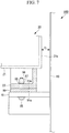
- Fig. 6 is a view of the spray pipe 20 and a portion around the spray pipe 20 of the desulfurization apparatus 100 taken along arrow II-II shown in Fig. 4 .
- Fig. 7 is a view of the spray pipe 20 and the portion around the spray pipe 20 of the desulfurization apparatus 100 taken along arrow III-III shown in Fig. 6 .
- the leg portion 23 shown in Fig. 6 and Fig. 7 are mounted on the lower end portion 21d of the distal end portion 21a of the pipe portion 21. As shown in Fig. 6 , an upper end of the leg portion 23 is mounted on the pipe portion 21. Further, a lower end of the leg portion 23 has an installation surface (first surface) 23a.
- the installation surface 23a is a flat installation surface extending along the horizontal plane. However, the installation surface 23a may adopt another mode. For example, the installation surface 23a may have a polygonal shape or an arcuate shape in cross section orthogonal to the axis X1.
- the pipe support 91 made of a metal material or the like is installed on an inner wall surface of the absorption tower 10.
- An upper end of the pipe support 91 has a support surface (second surface) 91a.
- the support surface 91a is a flat installation surface extending along the horizontal plane.
- the support surface 91a may adopt another mode.
- the support surface 91a may have a polygonal shape or an arcuate shape in cross section orthogonal to the axis X1.
- An upper surface of the support surface 91a may be covered by a lining made of a resin so as to protect the support surface 91a from corrosion or the like.
- a shim plate (plate-like member) 99 is disposed between the installation surface 23a on the lower end of the leg portion 23 and the support surface 91a on the upper end of the pipe support 91.
- the leg portion 23 is disposed in a state where the installation surface 23a is made to oppositely face the support surface 91a.
- the shim plate 99 is a member which adjusts a position of the installation surface 23a in the vertical direction with respect to the support surface 91a so as to install the pipe portion 21 along the horizontal direction.
- the shim plate 99 is disposed between the installation surface 23a and the support surface 91a.
- the shim plate 99 may not be disposed.
- the pipe portion 21 is disposed in a state where the installation surface 23a and the support surface 91a come into direct contact with each other.
- the shim plate 99 having an appropriate thickness in the vertical direction may be used.
- a plurality of shim plates 99 may be disposed in an overlapping manner.
- the leg portion 23, the pipe support 91, and the shim plate 99 are fastened to each other by fastening bolts (fastening portions) 95 and fastening nuts (fastening portions) 96, 97.
- a shaft portion of each fastening bolt 95 is inserted into the leg portion 23, the pipe support 91, and the shim plate 99 from a lower side of the pipe support 91.
- the fastening nuts 96, 97 are fastened to the shaft portion of the fastening bolt 95.
- a washer 98 is disposed between the fastening nut (fastening portion) 97 and the leg portion 23.
- Two fastening nuts 96, 97 are fastened to the shaft portion of each fastening bolt 95 so as to allow the formation of a gap below the fastening nut 97.
- the configuration where a gap is not formed below the fastening nut 97 is advantageous in the point that the leg portion 23, the pipe support 91, and the shim plate 99 are firmly connected with each other.
- the leg portion 23, the pipe support 91, and the shim plate 99 are firmly connected with each other, there is a possibility of a fastened portion being deformed or damaged when the pipe portion 21 is deformed due to thermal expansion.
- a gap is formed below the fastening nut 97.
- the fastening nut 96 is fastened.
- the fastening nut 97 is fastened and, thereafter, the fastening nut 96 is fastened and, further, the fastening nut 97 is loosened.
- a fastened state can be brought about where the fastening nut 96 and the fastening nut 97 do not move in the vertical direction. In this case, even when the pipe portion 21 is deformed due to thermal expansion, it is possible to reduce the problem that the fastened portion is deformed or damaged.
- leg portion 23 disposed at an intermediate portion of the pipe portion 21 between the distal end portion 21a and the proximal end portion 21b is described.
- Fig. 8 is a view of the spray pipe 20 and the portion around the spray pipe 20 of the desulfurization apparatus 100 taken along arrow IV-IV shown in Fig. 4 .
- Fig. 9 is a view of the spray pipe 20 and the portion around the spray pipe 20 of the desulfurization apparatus 100 taken along arrow V-V shown in Fig. 8 .
- the leg portion 23 shown in Fig. 8 and Fig. 9 is mounted on the intermediate portion of the pipe portion 21 between the distal end portion 21a and the proximal end portion 21b. As shown in Fig. 8 , an upper end of the leg portion 23 is mounted on the pipe portion 21. Further, a lower end of the leg portion 23 has an installation surface (first surface) 23a.
- the installation surface 23a is a flat installation surface extending along the horizontal plane. However, the installation surface 23a may adopt another mode. For example, the installation surface 23a may have a polygonal shape or an arcuate shape in cross section orthogonal to the axis X1.
- the support beam 92 and the support beam 93 which are made of a metal material or the like and extend in the horizontal direction, are installed on the absorption tower 10.
- An upper end of the support beam 92 has a support surface (second surface) 92a.
- an upper end of the support beam 93 has a support surface (second surface) 93a.
- the support surface 92a, 93a is a flat installation surface extending along the horizontal plane.
- the support surface 92a, 93a may adopt another mode.
- the support surface 92a, 93a may have a polygonal shape or an arcuate shape in cross section orthogonal to the axis X1.
- An upper surface of the support surface 92a, 93a may be covered by a lining made of a resin so as to protect the support surface 92a, 93a from corrosion or the like.
- a shim plate 99 is disposed between the installation surface 23a on the lower end of the leg portion 23 and the support surface 92a, 93a on the upper end of the support beam 92, 93.
- the leg portion 23 is disposed in a state where the installation surface 23a is made to oppositely face the support surface 92a, 93a.
- the shim plate 99 is a member which adjusts a position of the installation surface 23a in the vertical direction with respect to the support surface 92a, 93a so as to install the pipe portion 21 along the horizontal direction.
- the shim plate 99 is disposed between the installation surface 23a and the support surface 92a, 93a.
- the shim plate 99 may not be disposed.
- the pipe portion 21 is disposed in a state where the installation surface 23a and the support surface 92a, 93a come into direct contact with each other.
- the shim plate 99 having an appropriate thickness in the vertical direction may be used.
- a plurality of shim plates 99 may be disposed in an overlapping manner.
- the leg portion 23, the support beam 92, 93 and the shim plate 99 are fastened to each other by fastening bolts 95 and fastening nuts 96, 97.
- a shaft portion of each fastening bolt 95 is inserted into the leg portion 23, the support beam 92, 93 and the shim plate 99 from a lower side of the support beam 92, 93.
- the fastening nuts 96, 97 are fastened to the shaft portion of the fastening bolt 95.
- a washer 98 is disposed between the fastening nut 97 and the leg portion 23.
- Two fastening nuts 96, 97 are fastened to the shaft portion of each fastening bolt 95 so as to allow the formation of a gap below the fastening nut 97.
- the spray pipe 20 in this embodiment is made of fiber-reinforced plastic, and is formed by integrally molding the pipe portion 21, the nozzle holders 22b of the nozzle portions 22, and the leg portions 23.
- each spray nozzle 22a mounted on each nozzle holder 22b is made of SiC (silicon carbide), for example.
- the spray pipe 20 in this embodiment is manufactured such that the pipe portion 21, the nozzle holders 22b of the nozzle portions 22, and the leg portions 23 are formed into an integral body by molding using fiber-reinforced plastic and, thereafter, the spray nozzles 22a are mounted on the nozzle holders 22b.
- the spray pipe 20 is made of fiber-reinforced plastic thus having high resistance against wear.
- the spray pipe 20 also has high resistance against corrosion.
- a metal material for example, UNS S31254 or Hastelloy C-2766 may be used as a material for forming the spray pipe 20 in place of fiber-reinforced plastic.
- Fig. 10 is a cross-sectional view of the leg portion 23 taken along arrow VI-VI shown in Fig. 9 .
- the insertion holes 23b are formed in the installation surface 23a of the leg portion 23, and the fastening bolts 95 are inserted into the insertion holes 23b.
- a length L2 of the insertion hole 23b in the direction along the axis X1 is set longer than a length L1 of the insertion hole 23b in the direction orthogonal to the axis X1.
- the insertion hole 23b is formed as an elongated hole so as to reduce the problem that the insertion hole 23b comes into contact with the fastening bolt 95 when the spray pipe 20 thermally elongates thus causing the leg portion 23 to move toward the distal end portion 21a of the pipe portion 21.
- the insertion holes 23b formed in the installation surface 23a of the leg portion 23 are formed as elongated holes, and the insertion holes (not shown in the drawing) formed in the pipe support 91, and the support beam 92, 93 are formed as circular holes having a circular shape.
- the insertion holes 23b formed in the installation surface 23a of the leg portion 23 may be formed as circular holes having a circular shape
- the insertion holes formed in the pipe support 91, and the support beam 92, 93 may be formed as elongated holes where the length L2 in the direction along the axis X1 is set longer than the length L1 in the direction orthogonal to the axis X1.
- both of the insertion holes 23b formed in the installation surface 23a of the leg portion 23 and the insertion holes formed in the pipe support 91, and the support beam 92, 93 may be formed as elongated holes.
- cut-away portions 99a formed in the shim plate 99 are described.
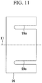
- Fig. 11 is a view of the plate-like member taken along arrow VI-VI shown in Fig. 9 .
- the cut-away portions 99a which open toward one end of the shim plate 99 are formed in the shim plate 99.
- the cut-away portion 99a is a portion which allows the insertion of the fastening bolt 95 in a state where the shim plate 99 is disposed between the installation surface 23a of the leg portion 23 and the support surface 92a, 93a of the support beam 92, 93.
- cut-away portion 99a is a portion which allows the insertion of the fastening bolt 95 in a state where the shim plate 99 is disposed between the installation surface 23a of the leg portion 23 and the support surface 91a of the pipe support 91 (see Fig. 7 ).
- the shim plate 99 Since the shim plate 99 has the cut-away portions 99a, the shim plate 99 can be inserted between the installation surface 23a of the leg portion 23 and the support surface 91a of the pipe support 91 without detaching the fastening bolts 95. In the same manner, since the shim plate 99 has the cut-away portions 99a, the shim plate 99 can be inserted between the installation surface 23a of the leg portion 23 and the support surface 92a, 93a of the support beam 92, 93 without detaching the fastening bolts 95. As described above, with the installation of the shim plates 99 at desired portions in installing the leg portions 23, which the spray pipe 20 includes, to the pipe support 91 and the support beam 92, 93, the spray pipe 20 can be adjusted to be disposed in the horizontal direction.
- the shim plate 99 is disposed in a state where openings formed in the shim plate 99 are directed toward the distal end portion 21a of the pipe portion 21 along the axis X1. That is, the cut-away portions 99a formed in the shim plate 99 do not open toward the proximal end portion 21b side of the pipe portion 21. With such a configuration, even when a force toward the distal end portion 21a is applied to the shim plate 99 from the leg portion 23, the shim plate 99 comes into contact with the fastening bolts 95 and hence, there is no possibility of the shim plate 99 moving toward the distal end portion 21a. Accordingly, it is possible to prevent the problem that the shim plate 99 moves toward the distal end portion 21a thus escaping from the pipe support 91 or the support beam 92, 93.
- the gap CL is formed between the distal end portion 21a of the pipe portion 21 and the inner wall surface of the absorption tower 10.
- the gap CL has a distance necessary for preventing the distal end portion 21a of the pipe portion 21 from coming into contact with the inner wall surface of the absorption tower 10.
- the spray pipe 20 thermally expands due to high temperature exhaust gas.
- the pipe portion 21 in this embodiment is disposed such that the gap CL can be ensured even when the spray pipe 20 is heated by exhaust gas. That is, in installing the spray pipe 20 (in a state equal to a state of being in an atmospheric temperature), the pipe portion 21 is installed such that the gap CL can be ensured even when the pipe portion 21 thermally elongates.
- the gap CL between the distal end portion 21a of the pipe portion 21 and the inner wall surface of the absorption tower 10 is set to 10 mm or more and 100 mm or less.
- Fig. 12 is a partially enlarged view of the mounting flange 24 and a portion around the mounting flange 24 of the spray pipe 20, shown in Fig. 4 , of the desulfurization apparatus 100.
- the opening portion 14 of the absorption tower 10 is formed into a cylindrical shape extending along the axis X1.
- a flange 14a is formed at an end portion of the opening portion 14.
- a lining portion 14b made of a resin is formed on an inner peripheral surface of the flange 14a so as to protect the flange 14a from corrosion or the like caused by exhaust gas.
- the mounting flange 24 of the spray pipe 20 is mounted on the flange 14a of the opening portion 14 by a plurality of fasteners (not shown in the drawing) with a gasket 14c (made of butyl rubber, for example) interposed therebetween.
- a gasket 14c made of butyl rubber, for example
- a sealant may be applied by coating between the mounting flange 24 and the gasket 14c.
- the sealant may be applied by coating instead of adjusting a thickness of the lining portion 14b.
- the sealant may be applied by coating in addition to the adjustment of a thickness of the lining portion 14b.
- the leg portions 23 each having the installation surface 23a along the horizontal direction are disposed at a plurality of positions on the lower end portion 21d of the pipe portion 21 in the vertical direction.
- the leg portions 23 are disposed in a state where the installation surfaces 23a are made to oppositely face the support surfaces 91a, 92a, 93a of the pipe support 91, the support beam 92, and the support beam 93 which are installed on the absorption tower 10. Further, a reaction force and an impact force are applied to the spray pipe 20 as the spray pipe 20 injects an absorbing liquid upward, and the reaction force and the impact force are transmitted from the installation surfaces 23a to the support surfaces 91a, 92a, 93a. Accordingly, it is possible to prevent a reaction force and an impact force from being locally applied to the spray pipe 20 thus reducing the problem of damaging the spray pipe 20.
- the leg portion 23 is arranged at a plurality of positions including the distal end portion 21a of the pipe portion 21.
- the load of the spray pipe 20 can be transmitted from the leg portion 23 to the support beams 92, 93 also at the intermediate portion disposed between the proximal end portion 21b and the distal end portion 21a. Accordingly, compared to the case where a load of the spray pipe 20 is not supported by the intermediate portion, it is possible to reduce the problem of the spray pipe 20 being deflected by its own weight.
- the desulfurization apparatus 100 of this embodiment includes the shim plate 99 disposed between the installation surface 23a and the support surface 91a, 92a, 93a.
- the shim plate 99 is disposed in a state where the cut-away portions 99a, each allowing the insertion of the fastening bolt 95, are opened toward the distal end portion 21a of the pipe portion 21.
- the spray pipe 20 can be accurately disposed along the horizontal plane.
- the spray pipe 20 thermally elongates along the axis X1 due to heating by exhaust gas.
- a force toward the distal end portion 21a of the pipe portion 21 is applied from the leg portion 23 to the shim plate 99 disposed in contact with the leg portion 23.
- the shim plate 99 is disposed in a state where the cut-away portions 99a do not open toward the proximal end portion 21b side of the pipe portion 21. Accordingly, even when a force toward the distal end portion 21a is applied to the shim plate 99 from the leg portion 23, the shim plate 99 comes into contact with the fastening bolts 95 and hence, there is no possibility of the shim plate 99 moving toward the distal end portion 21a. Accordingly, it is possible to prevent the problem that the shim plate 99 moves toward the distal end portion 21a thus escaping from the pipe support 91 or the support beam 92, 93.
- the insertion holes 23b into which the fastening bolts 95 are respectively inserted are formed in the installation surface 23a of the leg portion 23.
- the length L2 of the insertion hole 23b in the direction along the axis X1 is set longer than the length L1 of the insertion hole 23b in the direction orthogonal to the axis X1.
- the spray pipe 20 thermally elongates along the axis X1 due to heating by exhaust gas.
- the leg portion 23 mounted on the spray pipe 20 moves toward the distal end portion 21a of the pipe portion 21.
- the length L2 of the insertion hole 23b in the direction along the axis X1 is set longer. Therefore, it is possible to reduce the problem that the insertion hole 23b comes into contact with the fastening bolt 95 when the leg portion 23 moves due to thermal elongation.
- each pipe portion 21 is disposed so as to avoid contact with the inner peripheral surface of the absorption tower 10 in a state where the pipe portion 21 is heated by exhaust gas.
- the desulfurization apparatus 100 is an apparatus which uses the lime-gypsum method where an absorbing liquid containing lime is brought into gas-liquid contact with exhaust gas thus removing sulfur oxides contained in the exhaust gas.
- the desulfurization apparatus 100 may adopt another mode.
- the desulfurization apparatus 100 may be a desulfurization apparatus which uses a seawater desulfurization method where seawater containing an alkaline component is used as an absorbing liquid.
- the mounting flange 24 of the spray pipe 20 is mounted on the flange 14a of the opening portion 14 of the absorption tower 10.
- another mode may be adopted.
- the mounting flange 24 may be directly mounted on a side wall of the absorption tower 10 using fasteners.
Landscapes
- Engineering & Computer Science (AREA)
- Chemical & Material Sciences (AREA)
- Oil, Petroleum & Natural Gas (AREA)
- Analytical Chemistry (AREA)
- General Chemical & Material Sciences (AREA)
- Chemical Kinetics & Catalysis (AREA)
- Environmental & Geological Engineering (AREA)
- Health & Medical Sciences (AREA)
- Biomedical Technology (AREA)
- General Engineering & Computer Science (AREA)
- Mechanical Engineering (AREA)
- Treating Waste Gases (AREA)
- Gas Separation By Absorption (AREA)
- Nozzles (AREA)
Abstract
Description
- The present invention relates to a spray pipe and a desulfurization apparatus provided with the spray pipe.
- An exhaust gas system such as a boiler, installed in a power plant or the like, is provided with a desulfurization apparatus which removes sulfur oxides from exhaust gas. With the provision of the desulfurization apparatus, the amount of sulfur oxides contained in exhaust gas to be discharged to the atmosphere can be reduced.
- PTL 1 and PTL 2 disclose a liquid column type desulfurization apparatus where an absorbing liquid is injected upward from a plurality of nozzles, mounted on a branch pipe (header) installed horizontally, so as to remove sulfur oxides in a combustion exhaust gas via a chemical reaction between the combustion exhaust gas and the absorbing liquid.
-
- [PTL 1] Japanese Unexamined Patent Application, Publication No.
Hei9-225256 - [PTL 2]
U.S. Patent No. 6613133 - In the liquid column type desulfurization apparatus, a downward reaction force is applied to the branch pipe as the branch pipe injects an absorbing liquid upward. Further, a downward impact force is also applied to the branch pipe when the absorbing liquid, which the branch pipe injects upward, falls and comes into contact with the branch pipe.
- In PTL 1 (see
Fig. 1 andFig. 2 ), nozzles 6 which inject an absorbing liquid are mounted on a branch pipe 5, and the branch pipe 5 is supported by a plurality of support rods 9. The support rods 9 are arranged below the branch pipe so as to be orthogonal to the branch pipe 5, and the support rods 9 are separated at a distance from each other. Further, in PTL 1, the branch pipe 5 and each support rod 9 have a circular outer shape, and come into contact with each other at a position where the branch pipe 5 and each support rod 9 intersect with each other. Accordingly, there is a possibility of the branch pipe being damaged (including generation of cracks and local deformation) by local force acting at respective positions coming into contact with the support rods. - In PTL 2 (see
Fig. 1 andFig. 3 ), a branch pipe (header) 14, 15 is supported in a state of being restrained by U-shaped support straps 34 each having an upper end connected to a beam 32. Accordingly, there is a possibility of thebranch pipe branch pipe branch pipe - The present invention has been made under such circumstances, and an object of the present invention is to provide a spray pipe and a desulfurization apparatus provided with the spray pipe which can reduce the problem where a reaction force and an impact force are applied to the spray pipe as the spray pipe injects an absorbing liquid upward thus damaging the spray pipe.
- To solve the above-mentioned problem, the present invention adopts the following solutions.
- A spray pipe according to one aspect of the present invention is disposed along a horizontal direction in an absorption tower formed extending along a vertical direction to form a passage for exhaust gas, and the spray pipe includes: a pipe portion having a cylindrical shape, and configured to extend along an axis in the horizontal direction, a distal end portion of the pipe portion being closed; a plurality of nozzle portions configured to guide an absorbing liquid, flowing through the pipe portion in the horizontal direction, upward in a vertical direction, the plurality of nozzle portions being arranged at a plurality of positions on an upper end portion of the pipe portion in the vertical direction; and a leg portion disposed on a lower end portion of the pipe portion in the vertical direction, and having a first surface along the horizontal direction, wherein the leg portion is disposed in a state where the first surface is made to oppositely face a second surface of a support portion installed on the absorption tower, the second surface extending along the horizontal direction.
- With the spray pipe according to one aspect of the present invention, the leg portion having the first surface along the horizontal direction is disposed on the lower end portion of the pipe portion in the vertical direction. The leg portion is disposed in a state where the first surface is made to oppositely face the second surface of the support portion installed on the absorption tower. Further, a reaction force and an impact force are applied to the spray pipe as the spray pipe injects an absorbing liquid upward, and the reaction force and the impact force are transmitted from the first surface to the second surface. Accordingly, it is possible to prevent a reaction force and an impact force from being locally applied to the spray pipe thus reducing the problem of damaging the spray pipe.
- In the spray pipe according to one aspect of the present invention, the leg portion may be arranged at a plurality of positions including the distal end portion of the pipe portion.
- With such a configuration, while a load of the spray pipe is transmitted from the leg portion to the support portion of the desulfurization apparatus at the closed distal end portion of the pipe portion, the load of the spray pipe can be transmitted from the leg portion to the support portion of the desulfurization apparatus also at portions ranging from the intermediate portion to the distal end portion. Accordingly, compared to the case where a load of the spray pipe is not supported by the intermediate portion, it is possible to reduce the problem of the spray pipe being deflected by its own weight.
- In the spray pipe according to one aspect of the present invention, the pipe portion may be made of fiber-reinforced plastic.
- With such a configuration, it is possible to reduce the problem such as damage of the pipe portion caused by corrosion when the pipe portion is made of metal material, and wear of the pipe portion caused by impact or the like of an absorbing liquid on the pipe portion.
- In the spray pipe according to one aspect of the present invention, a length of the pipe portion along the axis from a proximal end portion to the distal end portion may be set to 3 m or more and 15 m or less, and an outer diameter of the pipe portion may be set to 200 mm or more and 400 mm or less.
- With such a configuration, it is possible to reduce the problem that the spray pipe which includes the pipe portion having a length of 3 m or more and 15 m or less and an outer diameter of 200 mm or more and 400 mm or less is damaged.
- A desulfurization apparatus according to one aspect of the present invention includes: an absorption tower formed extending along a vertical direction to form a passage for exhaust gas; a spray pipe disposed in the absorption tower along a horizontal direction; a support portion installed on the absorption tower so as to support the spray pipe; and a fastening portion configured to fasten the spray pipe and the support portion to each other, wherein the spray pipe includes: a pipe portion having a cylindrical shape, and configured to extend along an axis in the horizontal direction, a distal end portion of the pipe portion being closed; a plurality of nozzle portions configured to guide an absorbing liquid, flowing through the pipe portion in the horizontal direction, upward in the vertical direction, the plurality of nozzle portions being arranged at a plurality of positions on an upper end portion of the pipe portion in the vertical direction; and a leg portion disposed on a lower end portion of the pipe portion in the vertical direction, and having a first surface along the horizontal direction, wherein the support portion has a second surface along the horizontal direction, and the spray pipe is fastened to the support portion by the fastening portion in a state where the first surface is made to oppositely face the second surface.
- With the desulfurization apparatus according to one aspect of the present invention, the leg portion having the first surface along the horizontal direction is disposed on the lower end portion of the pipe portion of the spray pipe in the vertical direction. Further, the leg portion is disposed in a state where the first surface is made to oppositely face the second surface of the support portion installed on the absorption tower. Further, a reaction force and an impact force are applied to the spray pipe as the spray pipe injects the absorbing liquid upward, and the reaction force and the impact force are transmitted from the first surface to the second surface. Accordingly, it is possible to prevent a reaction force and an impact force from being locally applied to the spray pipe thus reducing the problem of damaging the spray pipe. Further, the spray pipe and the support portion are fastened to each other by the fastening portion and hence, even when a reaction force and an impact force are applied to the spray pipe, a state is maintained where the spray pipe is supported by the support portion.
- In the desulfurization apparatus according to one aspect of the present invention, it may be configured such that the desulfurization apparatus further includes a plate-like member disposed between the first surface and the second surface, the fastening portion includes a fastening bolt and a fastening nut fastened to the fastening bolt, the plate-like member has a cut-away portion which allows insertion of the fastening bolt in a state where the plate-like member is disposed between the first surface and the second surface, and the plate-like member is disposed in a state where the cut-away portion is opened toward the distal end portion of the pipe portion.
- To make the injection direction of an absorbing liquid injected from the spray pipe agrees with the vertical direction, it is necessary to accurately dispose the spray pipe along the horizontal plane. In disposing the spray pipe, by disposing the plate-like member having an appropriate thickness between the leg portion and the support portion, the spray pipe can be accurately disposed along the horizontal plane.
- The spray pipe thermally elongates along the axis due to heating by exhaust gas. When the spray pipe thermally elongates, a force toward the closed distal end portion of the pipe portion is applied from the leg portion to the plate-like member disposed in contact with the leg portion. The plate-like member is disposed in a state where the cut-away portion opens toward the distal end portion of the pipe portion. That is, the cut-away portion of the plate-like member does not open toward the proximal end portion side of the pipe portion. Accordingly, even when a force toward the distal end portion is applied to the plate-like member from the leg portion, the plate-like member comes into contact with the fastening bolt and hence, there is no possibility of the plate-like member moving toward the distal end portion. Accordingly, it is possible to prevent the problem that the plate-like member moves toward the distal end portion thus escaping from the support portion.
- In the desulfurization apparatus according to one aspect of the present invention, an insertion hole into which the fastening bolt is inserted may be formed in the first surface of the leg portion, and a length of the insertion hole in a direction along the axis may be set longer than a length of the insertion hole in a direction orthogonal to the axis.
- The spray pipe thermally elongates along the axis due to heating by exhaust gas. When the spray pipe thermally elongates, the leg portion mounted on the spray pipe moves toward the closed distal end portion of the pipe portion. According to the configuration of the present invention, a length of the insertion hole in the direction along the axis is set longer. Therefore, it is possible to reduce the problem that the insertion hole comes into contact with the fastening bolt when the leg portion moves due to thermal elongation.
- In the desulfurization apparatus according to one aspect of the present invention, the pipe portion may be disposed so as to avoid contact with an inner peripheral surface of the absorption tower in a state where the pipe portion is heated by exhaust gas. A distal end portion of the pipe portion is preferably disposed with a gap of 10 mm or more and 100 mm or less formed between the distal end portion and the inner wall surface of the absorption tower in a state where the pipe portion is not heated by exhaust gas.
- With such a configuration, it is possible to reduce the problem that the pipe portion is heated by exhaust gas thus thermally elongating and, as a result, the distal end portion of the pipe portion comes into contact with the inner peripheral surface of the absorption tower.
- According to the present invention, it is possible to provide a spray pipe and a desulfurization apparatus provided with the spray pipe which can reduce the problem where a reaction force and an impact force are applied to the spray pipe as the spray pipe injects an absorbing liquid upward thus damaging the spray pipe.
-
- [
Fig. 1 ]
Fig. 1 is a longitudinal cross-sectional view showing the schematic configuration of a desulfurization apparatus of one embodiment of the present invention. - [
Fig. 2 ]
Fig. 2 is a side view of spray pipes and a portion around the spray pipes of the desulfurization apparatus shown inFig. 1 . - [
Fig. 3 ]
Fig. 3 is a plan view of the spray pipe on an upper stage shown inFig. 2 as viewed from above. - [
Fig. 4 ]
Fig. 4 is a view of the spray pipe and a portion around the spray pipe of the desulfurization apparatus taken along arrow I-I shown inFig. 2 . - [
Fig. 5 ]
Fig. 5 is a partially enlarged view of a nozzle portion shown inFig. 2 . - [
Fig. 6 ]
Fig. 6 is a view of the spray pipe and a portion around the spray pipe of the desulfurization apparatus taken along arrow II-II shown inFig. 4 . - [
Fig. 7 ]
Fig. 7 is a view of the spray pipe and the portion around the spray pipe of the desulfurization apparatus taken along arrow III-III shown inFig. 6 . - [
Fig. 8 ]
Fig. 8 is a view of the spray pipe and the portion around the spray pipe of the desulfurization apparatus taken along arrow IV-IV shown inFig. 4 . - [
Fig. 9 ]
Fig. 9 is a view of the spray pipe and the portion around the spray pipe of the desulfurization apparatus taken along arrow V-V shown inFig. 8 . - [
Fig. 10 ]
Fig. 10 is a cross-sectional view of a leg portion taken along arrow VI-VI shown inFig. 9 . - [
Fig. 11 ]
Fig. 11 is a view of a plate-like member taken along arrow VI-VI shown inFig. 9 . - [
Fig. 12 ]
Fig. 12 is a partially enlarged view of a mounting flange and a portion around the mounting flange of the spray pipe, shown inFig. 4 , of the desulfurization apparatus. - Hereinafter, a
desulfurization apparatus 100 according to one embodiment of the present invention is described with reference to drawings. - As shown in
Fig. 1 , thedesulfurization apparatus 100 of this embodiment includes: anabsorption tower 10;spray pipes 20; ademister 30; and acirculation pump 40. - The
absorption tower 10 is a cylindrical casing formed extending in the vertical direction to form a passage for exhaust gas. Exhaust gas containing sulfur oxides is introduced into theabsorption tower 10 from an exhaustgas introduction portion 11 formed on a side surface of theabsorption tower 10, and theabsorption tower 10 guides the exhaust gas upward in the vertical direction. Further, theabsorption tower 10 discharges the exhaust gas from an exhaustgas discharge portion 12 formed on the upper side of theabsorption tower 10 in the vertical direction. - The
spray pipes 20 are cylindrical members arranged in the inside of theabsorption tower 10 along the horizontal direction. As shown inFig. 1 , thespray pipes 20 inject an absorbing liquid upward in the vertical direction thus causing exhaust gas introduced from the exhaustgas introduction portion 11 and the absorbing liquid to be brought into gas-liquid contact with each other. In this embodiment, the absorbing liquid is a liquid containing lime so that sulfur oxides contained in the exhaust gas is removed by the lime-gypsum method. The absorbing liquid injected from thespray pipes 20 accumulates at abottom portion 13 of theabsorption tower 10. The absorbing liquid accumulated at thebottom portion 13 is supplied to thespray pipes 20 by thecirculation pump 40. - The
demister 30 is a folded-plate-shaped demister, for example. Thedemister 30 removes a mist of absorbing liquid generated in the inside of theabsorption tower 10 via physical impact. - Next, the structure of the
spray pipes 20, which thedesulfurization apparatus 100 of this embodiment includes, and a portion around thespray pipes 20 is described in detail. -
Fig. 2 is a side view of thespray pipes 20 and a portion around thespray pipes 20 of thedesulfurization apparatus 100 shown inFig. 1 . - As shown in
Fig. 2 , in thedesulfurization apparatus 100, the plurality ofspray pipes 20 are inserted into the inside of theabsorption tower 10 from the outside of theabsorption tower 10. In thedesulfurization apparatus 100, fivespray pipes 20 are arranged at a predetermined position in the vertical direction, and are arranged at equal intervals in the horizontal direction. The number ofspray pipes 20 which thedesulfurization apparatus 100 includes may be set to a desired number other than five depending on a size or the like of theabsorption tower 10. Thespray pipes 20 may be arranged such that a plurality ofspray pipes 20 are arranged on each of a plurality of stages at different positions in the vertical direction. - As shown in
Fig. 2 , a mountingflange 24 and asupply port 25 are formed on eachspray pipe 20. The mountingflange 24 is a member for mounting thespray pipe 20 on anopening portion 14 formed on theabsorption tower 10. The mountingflange 24 is mounted on the openingportion 14 of theabsorption tower 10 by a plurality of fasteners (not shown in the drawing) (seeFig. 4 ). - An
access hatch 15, which allows an operator to pass through the side surface of theabsorption tower 10, is mounted on the side surface of theabsorption tower 10. Theaccess hatch 15 can be also used when a maintenance component or the like is brought to the inside from the outside of theabsorption tower 10 or when a used component or the like is carried out to the outside from the inside of theabsorption tower 10. -
Fig. 3 is a plan view of the fivespray pipes 20 shown inFig. 2 as viewed from above.Fig. 4 is a view of thespray pipe 20 and a portion around thespray pipe 20 of thedesulfurization apparatus 100 taken along arrow I-I shown inFig. 2 . - As shown in
Fig. 3 andFig. 4 , eachspray pipe 20 includes apipe portion 21, a plurality ofnozzle portions 22, and a plurality ofleg portions 23. - The
pipe portion 21 is a circular cylindrical member which extends in a linear shape along an axis X1 in the horizontal direction from aproximal end portion 21b to adistal end portion 21a, and has the closeddistal end portion 21a. Thesupply port 25 is formed on theproximal end portion 21b of thepipe portion 21, and an absorbing liquid is supplied to thesupply port 25 from thecirculation pump 40. Thedistal end portion 21a of thepipe portion 21 is closed so that the absorbing liquid supplied to the inside of thepipe portion 21 from thesupply port 25 is guided to the plurality ofnozzle portions 22. A length of thepipe portion 21 along the axis X1 from theproximal end portion 21b to thedistal end portion 21a is set to 3 m or more and 15 m or less. Further, an outer diameter of thepipe portion 21 is set to 200 mm or more and 400 mm or less. - The plurality of
nozzle portions 22 are members arranged at equal intervals along the axis X1 at a plurality of positions on anupper end portion 21c of thepipe portion 21 in the vertical direction. In this embodiment,Fig. 5 is a partially enlarged view of thenozzle portion 22 shown inFig. 2 . As shown inFig. 5 , thenozzle portion 22 includes aspray nozzle 22a, anozzle holder 22b, and agasket 22c. - The
spray nozzle 22a is a member which guides an absorbing liquid, flowing through thepipe portion 21 in the horizontal direction along the axis X1, upward in the vertical direction along an axis X2. Thespray nozzle 22a injects the absorbing liquid, supplied from thecirculation pump 40, upward in the vertical direction thus causing exhaust gas and the absorbing liquid to be brought into gas-liquid contact with each other in the inside of theabsorption tower 10. Thespray nozzle 22a is made of SiC (silicon carbide), for example. - The
nozzle holder 22b is a member which is mounted on theupper end portion 21c of thepipe portion 21, and is formed into a circular cylindrical shape along the axis X2 in the vertical direction. As shown inFig. 5 , the lower end side of thespray nozzle 22a is inserted into the inside of thenozzle holder 22b, and a flange is formed at an upper end of thenozzle holder 22b. Further, a flange is formed on thespray nozzle 22a, and the flange has the same shape as the flange of thenozzle holder 22b. As shown inFig. 5 , the flange of thespray nozzle 22a and the flange of thenozzle holder 22b are fastened to each other by a plurality of fasteners (not shown in the drawing) with theannular gasket 22c (made of butyl rubber, for example) interposed therebetween. - As shown in
Fig. 4 , the plurality ofleg portions 23 are members arranged on alower end portion 21d of thepipe portion 21. Theleg portions 23 are arranged at a plurality of positions including thedistal end portion 21a of thepipe portion 21. The plurality ofleg portions 23 transmits a load of thepipe portion 21 to a pipe support (support portion) 91, a support beam (support portion) 92, and a support beam (support portion) 93. Thepipe support 91, thesupport beam 92, and thesupport beam 93 are installed on theabsorption tower 10. Thepipe support 91, thesupport beam 92, and thesupport beam 93 are members which are installed on theabsorption tower 10 so as to support thespray pipes 20. A reaction force applied to thepipe portion 21 when thepipe portion 21 injects an absorbing liquid and an impact force generated when an absorbing liquid falls and comes into contact with thepipe portion 21 are transmitted to theabsorption tower 10 by way of the plurality ofleg portions 23. - The
leg portion 23 arranged at thedistal end portion 21a of thepipe portion 21 is described. -
Fig. 6 is a view of thespray pipe 20 and a portion around thespray pipe 20 of thedesulfurization apparatus 100 taken along arrow II-II shown inFig. 4 .Fig. 7 is a view of thespray pipe 20 and the portion around thespray pipe 20 of thedesulfurization apparatus 100 taken along arrow III-III shown inFig. 6 . Theleg portion 23 shown inFig. 6 andFig. 7 are mounted on thelower end portion 21d of thedistal end portion 21a of thepipe portion 21. As shown inFig. 6 , an upper end of theleg portion 23 is mounted on thepipe portion 21. Further, a lower end of theleg portion 23 has an installation surface (first surface) 23a. Theinstallation surface 23a is a flat installation surface extending along the horizontal plane. However, theinstallation surface 23a may adopt another mode. For example, theinstallation surface 23a may have a polygonal shape or an arcuate shape in cross section orthogonal to the axis X1. - As shown in
Fig. 7 , thepipe support 91 made of a metal material or the like is installed on an inner wall surface of theabsorption tower 10. An upper end of thepipe support 91 has a support surface (second surface) 91a. Thesupport surface 91a is a flat installation surface extending along the horizontal plane. However, thesupport surface 91a may adopt another mode. For example, thesupport surface 91a may have a polygonal shape or an arcuate shape in cross section orthogonal to the axis X1. An upper surface of thesupport surface 91a may be covered by a lining made of a resin so as to protect thesupport surface 91a from corrosion or the like. - As shown in
Fig. 6 andFig. 7 , a shim plate (plate-like member) 99 is disposed between theinstallation surface 23a on the lower end of theleg portion 23 and thesupport surface 91a on the upper end of thepipe support 91. - As shown in
Fig. 6 andFig. 7 , theleg portion 23 is disposed in a state where theinstallation surface 23a is made to oppositely face thesupport surface 91a. - The
shim plate 99 is a member which adjusts a position of theinstallation surface 23a in the vertical direction with respect to thesupport surface 91a so as to install thepipe portion 21 along the horizontal direction. InFig. 6 andFig. 7 , theshim plate 99 is disposed between theinstallation surface 23a and thesupport surface 91a. However, when theshim plate 99 is unnecessary for installing thepipe portion 21 along the horizontal direction, theshim plate 99 may not be disposed. In such a case, thepipe portion 21 is disposed in a state where theinstallation surface 23a and thesupport surface 91a come into direct contact with each other. Further, to install thepipe portion 21 along the horizontal direction, theshim plate 99 having an appropriate thickness in the vertical direction may be used. Alternatively, a plurality ofshim plates 99 may be disposed in an overlapping manner. - As shown in
Fig. 6 andFig. 7 , theleg portion 23, thepipe support 91, and theshim plate 99 are fastened to each other by fastening bolts (fastening portions) 95 and fastening nuts (fastening portions) 96, 97. A shaft portion of eachfastening bolt 95 is inserted into theleg portion 23, thepipe support 91, and theshim plate 99 from a lower side of thepipe support 91. Thefastening nuts fastening bolt 95. Awasher 98 is disposed between the fastening nut (fastening portion) 97 and theleg portion 23. - Two
fastening nuts fastening bolt 95 so as to allow the formation of a gap below thefastening nut 97. The configuration where a gap is not formed below thefastening nut 97 is advantageous in the point that theleg portion 23, thepipe support 91, and theshim plate 99 are firmly connected with each other. On the other hand, in the configuration where theleg portion 23, thepipe support 91, and theshim plate 99 are firmly connected with each other, there is a possibility of a fastened portion being deformed or damaged when thepipe portion 21 is deformed due to thermal expansion. In this embodiment, a gap is formed below thefastening nut 97. In such a state, thefastening nut 96 is fastened. Alternatively, thefastening nut 97 is fastened and, thereafter, thefastening nut 96 is fastened and, further, thefastening nut 97 is loosened. With such operations, a fastened state can be brought about where thefastening nut 96 and thefastening nut 97 do not move in the vertical direction. In this case, even when thepipe portion 21 is deformed due to thermal expansion, it is possible to reduce the problem that the fastened portion is deformed or damaged. - Next, the
leg portion 23 disposed at an intermediate portion of thepipe portion 21 between thedistal end portion 21a and theproximal end portion 21b is described. -
Fig. 8 is a view of thespray pipe 20 and the portion around thespray pipe 20 of thedesulfurization apparatus 100 taken along arrow IV-IV shown inFig. 4 .Fig. 9 is a view of thespray pipe 20 and the portion around thespray pipe 20 of thedesulfurization apparatus 100 taken along arrow V-V shown inFig. 8 . Theleg portion 23 shown inFig. 8 andFig. 9 is mounted on the intermediate portion of thepipe portion 21 between thedistal end portion 21a and theproximal end portion 21b. As shown inFig. 8 , an upper end of theleg portion 23 is mounted on thepipe portion 21. Further, a lower end of theleg portion 23 has an installation surface (first surface) 23a. Theinstallation surface 23a is a flat installation surface extending along the horizontal plane. However, theinstallation surface 23a may adopt another mode. For example, theinstallation surface 23a may have a polygonal shape or an arcuate shape in cross section orthogonal to the axis X1. - As shown in
Fig. 3 andFig. 8 , thesupport beam 92 and thesupport beam 93, which are made of a metal material or the like and extend in the horizontal direction, are installed on theabsorption tower 10. An upper end of thesupport beam 92 has a support surface (second surface) 92a. In the same manner, an upper end of thesupport beam 93 has a support surface (second surface) 93a. - The
support surface support surface support surface support surface support surface - As shown in
Fig. 8 andFig. 9 , ashim plate 99 is disposed between theinstallation surface 23a on the lower end of theleg portion 23 and thesupport surface support beam - As shown in
Fig. 8 andFig. 9 , theleg portion 23 is disposed in a state where theinstallation surface 23a is made to oppositely face thesupport surface - The
shim plate 99 is a member which adjusts a position of theinstallation surface 23a in the vertical direction with respect to thesupport surface pipe portion 21 along the horizontal direction. InFig. 8 andFig. 9 , theshim plate 99 is disposed between theinstallation surface 23a and thesupport surface shim plate 99 is unnecessary for installing thepipe portion 21 along the horizontal direction, theshim plate 99 may not be disposed. In such a case, thepipe portion 21 is disposed in a state where theinstallation surface 23a and thesupport surface pipe portion 21 along the horizontal direction, theshim plate 99 having an appropriate thickness in the vertical direction may be used. Alternatively, a plurality ofshim plates 99 may be disposed in an overlapping manner. - As shown in
Fig. 8 andFig. 9 , theleg portion 23, thesupport beam shim plate 99 are fastened to each other by fasteningbolts 95 andfastening nuts fastening bolt 95 is inserted into theleg portion 23, thesupport beam shim plate 99 from a lower side of thesupport beam fastening nuts fastening bolt 95. Awasher 98 is disposed between thefastening nut 97 and theleg portion 23. - Two
fastening nuts fastening bolt 95 so as to allow the formation of a gap below thefastening nut 97. - A method for manufacturing the
spray pipe 20 is described. Thespray pipe 20 in this embodiment is made of fiber-reinforced plastic, and is formed by integrally molding thepipe portion 21, thenozzle holders 22b of thenozzle portions 22, and theleg portions 23. On the other hand, eachspray nozzle 22a mounted on eachnozzle holder 22b is made of SiC (silicon carbide), for example. - The
spray pipe 20 in this embodiment is manufactured such that thepipe portion 21, thenozzle holders 22b of thenozzle portions 22, and theleg portions 23 are formed into an integral body by molding using fiber-reinforced plastic and, thereafter, thespray nozzles 22a are mounted on thenozzle holders 22b. There is a high possibility of wear to thespray pipe 20 due to impact or the like of an absorbing liquid which thespray pipe 20 injects upward. In this embodiment, thespray pipe 20 is made of fiber-reinforced plastic thus having high resistance against wear. Thespray pipe 20 also has high resistance against corrosion. - A metal material (for example, UNS S31254 or Hastelloy C-276) may be used as a material for forming the
spray pipe 20 in place of fiber-reinforced plastic. - Next,
insertion holes 23b formed in theleg portion 23 are described. -
Fig. 10 is a cross-sectional view of theleg portion 23 taken along arrow VI-VI shown inFig. 9 . As shown inFig. 10 , the insertion holes 23b are formed in theinstallation surface 23a of theleg portion 23, and thefastening bolts 95 are inserted into the insertion holes 23b. A length L2 of theinsertion hole 23b in the direction along the axis X1 is set longer than a length L1 of theinsertion hole 23b in the direction orthogonal to the axis X1. Theinsertion hole 23b is formed as an elongated hole so as to reduce the problem that theinsertion hole 23b comes into contact with thefastening bolt 95 when thespray pipe 20 thermally elongates thus causing theleg portion 23 to move toward thedistal end portion 21a of thepipe portion 21. - In this embodiment, the
insertion holes 23b formed in theinstallation surface 23a of theleg portion 23 are formed as elongated holes, and the insertion holes (not shown in the drawing) formed in thepipe support 91, and thesupport beam insertion holes 23b formed in theinstallation surface 23a of theleg portion 23 may be formed as circular holes having a circular shape, and the insertion holes formed in thepipe support 91, and thesupport beam insertion holes 23b formed in theinstallation surface 23a of theleg portion 23 and the insertion holes formed in thepipe support 91, and thesupport beam - Next, cut-away
portions 99a formed in theshim plate 99 are described. -
Fig. 11 is a view of the plate-like member taken along arrow VI-VI shown inFig. 9 . As shown inFig. 11 , the cut-awayportions 99a which open toward one end of theshim plate 99 are formed in theshim plate 99. The cut-awayportion 99a is a portion which allows the insertion of thefastening bolt 95 in a state where theshim plate 99 is disposed between theinstallation surface 23a of theleg portion 23 and thesupport surface support beam portion 99a is a portion which allows the insertion of thefastening bolt 95 in a state where theshim plate 99 is disposed between theinstallation surface 23a of theleg portion 23 and thesupport surface 91a of the pipe support 91 (seeFig. 7 ). - Since the
shim plate 99 has the cut-awayportions 99a, theshim plate 99 can be inserted between theinstallation surface 23a of theleg portion 23 and thesupport surface 91a of thepipe support 91 without detaching thefastening bolts 95. In the same manner, since theshim plate 99 has the cut-awayportions 99a, theshim plate 99 can be inserted between theinstallation surface 23a of theleg portion 23 and thesupport surface support beam fastening bolts 95. As described above, with the installation of theshim plates 99 at desired portions in installing theleg portions 23, which thespray pipe 20 includes, to thepipe support 91 and thesupport beam spray pipe 20 can be adjusted to be disposed in the horizontal direction. - The
shim plate 99 is disposed in a state where openings formed in theshim plate 99 are directed toward thedistal end portion 21a of thepipe portion 21 along the axis X1. That is, the cut-awayportions 99a formed in theshim plate 99 do not open toward theproximal end portion 21b side of thepipe portion 21. With such a configuration, even when a force toward thedistal end portion 21a is applied to theshim plate 99 from theleg portion 23, theshim plate 99 comes into contact with thefastening bolts 95 and hence, there is no possibility of theshim plate 99 moving toward thedistal end portion 21a. Accordingly, it is possible to prevent the problem that theshim plate 99 moves toward thedistal end portion 21a thus escaping from thepipe support 91 or thesupport beam - Next, a gap CL formed between the
distal end portion 21a of thepipe portion 21 of thespray pipe 20 and the inner wall surface of theabsorption tower 10 is described. - As shown in
Fig. 7 , the gap CL is formed between thedistal end portion 21a of thepipe portion 21 and the inner wall surface of theabsorption tower 10. The gap CL has a distance necessary for preventing thedistal end portion 21a of thepipe portion 21 from coming into contact with the inner wall surface of theabsorption tower 10. Thespray pipe 20 thermally expands due to high temperature exhaust gas. Accordingly, thepipe portion 21 in this embodiment is disposed such that the gap CL can be ensured even when thespray pipe 20 is heated by exhaust gas. That is, in installing the spray pipe 20 (in a state equal to a state of being in an atmospheric temperature), thepipe portion 21 is installed such that the gap CL can be ensured even when thepipe portion 21 thermally elongates. In this embodiment, in a state where thespray pipe 20 is not heated by exhaust gas, the gap CL between thedistal end portion 21a of thepipe portion 21 and the inner wall surface of theabsorption tower 10 is set to 10 mm or more and 100 mm or less. - Next, the structure for mounting the mounting
flange 24 of thespray pipe 20 on the openingportion 14 of theabsorption tower 10 is described. -
Fig. 12 is a partially enlarged view of the mountingflange 24 and a portion around the mountingflange 24 of thespray pipe 20, shown inFig. 4 , of thedesulfurization apparatus 100. As shown inFig. 12 , the openingportion 14 of theabsorption tower 10 is formed into a cylindrical shape extending along the axis X1. Aflange 14a is formed at an end portion of the openingportion 14. A liningportion 14b made of a resin is formed on an inner peripheral surface of theflange 14a so as to protect theflange 14a from corrosion or the like caused by exhaust gas. - The mounting
flange 24 of thespray pipe 20 is mounted on theflange 14a of the openingportion 14 by a plurality of fasteners (not shown in the drawing) with a gasket 14c (made of butyl rubber, for example) interposed therebetween. In this embodiment, when an end surface of the openingportion 14 is inclined from the vertical direction, thespray pipe 20 mounted on the openingportion 14 is inclined from the horizontal direction. Accordingly, to make the end surface of the openingportion 14 agree with the vertical direction, a thickness of a portion of thelining portion 14b which is sandwiched between the end surface of the openingportion 14 and the mountingflange 24 is appropriately adjusted. To make the end surface of the openingportion 14 agree with the vertical direction, a sealant may be applied by coating between the mountingflange 24 and the gasket 14c. The sealant may be applied by coating instead of adjusting a thickness of thelining portion 14b. Alternatively, the sealant may be applied by coating in addition to the adjustment of a thickness of thelining portion 14b. - The manner of operation and advantageous effects which the above-described
desulfurization apparatus 100 of this embodiment can acquire are described. - In the
spray pipe 20 provided to thedesulfurization apparatus 100 of this embodiment, theleg portions 23 each having theinstallation surface 23a along the horizontal direction are disposed at a plurality of positions on thelower end portion 21d of thepipe portion 21 in the vertical direction. Theleg portions 23 are disposed in a state where the installation surfaces 23a are made to oppositely face the support surfaces 91a, 92a, 93a of thepipe support 91, thesupport beam 92, and thesupport beam 93 which are installed on theabsorption tower 10. Further, a reaction force and an impact force are applied to thespray pipe 20 as thespray pipe 20 injects an absorbing liquid upward, and the reaction force and the impact force are transmitted from the installation surfaces 23a to the support surfaces 91a, 92a, 93a. Accordingly, it is possible to prevent a reaction force and an impact force from being locally applied to thespray pipe 20 thus reducing the problem of damaging thespray pipe 20. - In the
spray pipe 20 in this embodiment, theleg portion 23 is arranged at a plurality of positions including thedistal end portion 21a of thepipe portion 21. With such a configuration, while a load of thespray pipe 20 is transmitted from theleg portion 23 to thepipe support 91 of thedesulfurization apparatus 100 at thedistal end portion 21a, the load of thespray pipe 20 can be transmitted from theleg portion 23 to the support beams 92, 93 also at the intermediate portion disposed between theproximal end portion 21b and thedistal end portion 21a. Accordingly, compared to the case where a load of thespray pipe 20 is not supported by the intermediate portion, it is possible to reduce the problem of thespray pipe 20 being deflected by its own weight. - The
desulfurization apparatus 100 of this embodiment includes theshim plate 99 disposed between theinstallation surface 23a and thesupport surface shim plate 99 is disposed in a state where the cut-awayportions 99a, each allowing the insertion of thefastening bolt 95, are opened toward thedistal end portion 21a of thepipe portion 21. - To make the injection direction of an absorbing liquid injected from the
spray pipe 20 agree with the vertical direction, it is necessary to accurately dispose thespray pipe 20 along the horizontal plane. In disposing thespray pipe 20, by disposing theshim plate 99 having an appropriate thickness between theleg portion 23 and thepipe support 91 or thesupport beam spray pipe 20 can be accurately disposed along the horizontal plane. - The
spray pipe 20 thermally elongates along the axis X1 due to heating by exhaust gas. When thespray pipe 20 thermally elongates, a force toward thedistal end portion 21a of thepipe portion 21 is applied from theleg portion 23 to theshim plate 99 disposed in contact with theleg portion 23. Theshim plate 99 is disposed in a state where the cut-awayportions 99a do not open toward theproximal end portion 21b side of thepipe portion 21. Accordingly, even when a force toward thedistal end portion 21a is applied to theshim plate 99 from theleg portion 23, theshim plate 99 comes into contact with thefastening bolts 95 and hence, there is no possibility of theshim plate 99 moving toward thedistal end portion 21a. Accordingly, it is possible to prevent the problem that theshim plate 99 moves toward thedistal end portion 21a thus escaping from thepipe support 91 or thesupport beam - In the
desulfurization apparatus 100 of this embodiment, the insertion holes 23b into which thefastening bolts 95 are respectively inserted are formed in theinstallation surface 23a of theleg portion 23. The length L2 of theinsertion hole 23b in the direction along the axis X1 is set longer than the length L1 of theinsertion hole 23b in the direction orthogonal to the axis X1. - The
spray pipe 20 thermally elongates along the axis X1 due to heating by exhaust gas. When thespray pipe 20 thermally elongates, theleg portion 23 mounted on thespray pipe 20 moves toward thedistal end portion 21a of thepipe portion 21. According to this embodiment, the length L2 of theinsertion hole 23b in the direction along the axis X1 is set longer. Therefore, it is possible to reduce the problem that theinsertion hole 23b comes into contact with thefastening bolt 95 when theleg portion 23 moves due to thermal elongation. - In the
desulfurization apparatus 100 of this embodiment, eachpipe portion 21 is disposed so as to avoid contact with the inner peripheral surface of theabsorption tower 10 in a state where thepipe portion 21 is heated by exhaust gas. - With such a configuration, it is possible to reduce the problem that the
pipe portion 21 is heated by exhaust gas thus thermally elongating and, as a result, thedistal end portion 21a of thepipe portion 21 comes into contact with the inner peripheral surface of theabsorption tower 10. - In the description made heretofore, the
desulfurization apparatus 100 is an apparatus which uses the lime-gypsum method where an absorbing liquid containing lime is brought into gas-liquid contact with exhaust gas thus removing sulfur oxides contained in the exhaust gas. However, thedesulfurization apparatus 100 may adopt another mode. For example, thedesulfurization apparatus 100 may be a desulfurization apparatus which uses a seawater desulfurization method where seawater containing an alkaline component is used as an absorbing liquid. - In the description made heretofore, the mounting
flange 24 of thespray pipe 20 is mounted on theflange 14a of the openingportion 14 of theabsorption tower 10. However, another mode may be adopted. For example, when theflange 14a is not formed on the openingportion 14 of theabsorption tower 10, the mountingflange 24 may be directly mounted on a side wall of theabsorption tower 10 using fasteners. -
- 10
- absorption tower
- 11
- exhaust gas introduction portion
- 12
- exhaust gas discharge portion
- 13
- bottom portion
- 14
- opening portion
- 14a
- flange
- 14b
- lining portion
- 14c
- gasket
- 15
- access hatch
- 20
- spray pipe
- 21
- pipe portion
- 21a
- distal end portion
- 21b
- proximal end portion
- 21c
- upper end portion
- 21d
- lower end portion
- 22
- nozzle portion
- 22a
- spray nozzle
- 22b
- nozzle holder
- 22c
- gasket
- 23
- leg portion
- 23a
- installation surface (first surface)
- 23b
- insertion hole
- 24
- mounting flange
- 25
- supply port
- 30
- demister
- 40
- circulation pump
- 91
- pipe support (support portion)
- 91a
- support surface (second surface)
- 92, 93
- support beam (support portion)
- 92a, 93a
- support surface (second surface)
- 95
- fastening bolt (fastening portion)
- 96
- fastening nut (fastening portion)
- 97
- fastening nut (fastening portion)
- 98
- washer
- 99
- shim plate (plate-like member)
- 99a
- cut-away portion
- 100
- desulfurization apparatus
- CL
- gap
- X1, X2
- axis
Claims (9)
- A spray pipe which is disposed along a horizontal direction in an absorption tower formed extending along a vertical direction to form a passage for exhaust gas, the spray pipe comprising:a pipe portion having a cylindrical shape, and configured to extend along an axis in the horizontal direction, a distal end portion of the pipe portion being closed;a plurality of nozzle portions configured to guide an absorbing liquid, flowing through the pipe portion in the horizontal direction, upward in a vertical direction, the plurality of nozzle portions being arranged at a plurality of positions on an upper end portion of the pipe portion in the vertical direction; anda leg portion disposed on a lower end portion of the pipe portion in the vertical direction, and having a first surface along the horizontal direction, whereinthe leg portion is disposed in a state where the first surface is made to oppositely face a second surface of a support portion installed on the absorption tower, the second surface extending along the horizontal direction.
- The spray pipe according to claim 1, wherein
the leg portion is arranged at a plurality of positions including the distal end portion of the pipe portion. - The spray pipe according to claim 1 or 2, wherein
the pipe portion is made of fiber-reinforced plastic. - The spray pipe according to any one of claim 1 to claim 3, wherein
a length of the pipe portion along the axis from a proximal end portion to the distal end portion is set to 3 m or more and 15 m or less, and an outer diameter of the pipe portion is set to 200 mm or more and 400 mm or less. - A desulfurization apparatus comprising:an absorption tower formed extending along a vertical direction to form a passage for exhaust gas;a spray pipe disposed in the absorption tower along a horizontal direction;a support portion installed on the absorption tower so as to support the spray pipe; anda fastening portion configured to fasten the spray pipe and the support portion to each other, whereinthe spray pipe includes:a pipe portion having a cylindrical shape, and configured to extend along an axis in the horizontal direction, a distal end portion of the pipe portion being closed;a plurality of nozzle portions configured to guide an absorbing liquid, flowing through the pipe portion in the horizontal direction, upward in the vertical direction, the plurality of nozzle portions being arranged at a plurality of positions on an upper end portion of the pipe portion in the vertical direction; anda leg portion disposed on a lower end portion of the pipe portion in the vertical direction, and having a first surface along the horizontal direction, whereinthe support portion has a second surface along the horizontal direction, andthe spray pipe is fastened to the support portion by the fastening portion in a state where the first surface is made to oppositely face the second surface.
- The desulfurization apparatus according to claim 5 further comprising a plate-like member disposed between the first surface and the second surface, wherein
the fastening portion includes a fastening bolt and a fastening nut fastened to the fastening bolt,
the plate-like member has a cut-away portion which allows insertion of the fastening bolt in a state where the plate-like member is disposed between the first surface and the second surface, and
the plate-like member is disposed in a state where the cut-away portion is opened toward the distal end portion of the pipe portion. - The desulfurization apparatus according to claim 6, wherein
an insertion hole into which the fastening bolt is inserted is formed in the first surface of the leg portion, and
a length of the insertion hole in a direction along the axis is set longer than a length of the insertion hole in a direction orthogonal to the axis. - The desulfurization apparatus according to any one of claim 5 to claim 7, wherein
the pipe portion is disposed so as to avoid contact with an inner peripheral surface of the absorption tower in a state where the pipe portion is heated by exhaust gas. - The desulfurization apparatus according to claim 8, wherein
a distal end portion of the pipe portion is disposed with a gap of 10 mm or more and 100 mm or less formed between the distal end portion and the inner wall surface of the absorption tower in a state where the pipe portion is not heated by exhaust gas.
Applications Claiming Priority (2)
| Application Number | Priority Date | Filing Date | Title |
|---|---|---|---|
| JP2017114704A JP6215503B1 (en) | 2017-06-09 | 2017-06-09 | Spray pipe and desulfurization apparatus provided with the same |
| PCT/JP2017/023108 WO2018225273A1 (en) | 2017-06-09 | 2017-06-22 | Spray pipe and desulfurization device provided with same |
Publications (2)
| Publication Number | Publication Date |
|---|---|
| EP3636334A1 true EP3636334A1 (en) | 2020-04-15 |
| EP3636334A4 EP3636334A4 (en) | 2021-03-03 |
Family
ID=60107410
Family Applications (1)
| Application Number | Title | Priority Date | Filing Date |
|---|---|---|---|
| EP17912893.9A Withdrawn EP3636334A4 (en) | 2017-06-09 | 2017-06-22 | Spray pipe and desulfurization device provided with same |
Country Status (7)
| Country | Link |
|---|---|
| US (1) | US20200094186A1 (en) |
| EP (1) | EP3636334A4 (en) |
| JP (1) | JP6215503B1 (en) |
| KR (1) | KR101922362B1 (en) |
| CN (1) | CN109414644A (en) |
| MY (1) | MY196258A (en) |
| WO (1) | WO2018225273A1 (en) |
Families Citing this family (7)
| Publication number | Priority date | Publication date | Assignee | Title |
|---|---|---|---|---|
| JP6651483B2 (en) | 2017-07-14 | 2020-02-19 | 三菱日立パワーシステムズ株式会社 | Installation method of spray pipe |
| WO2021079527A1 (en) * | 2019-10-25 | 2021-04-29 | 三菱パワー株式会社 | Flue gas desulfurization apparatus |
| CN111706581A (en) * | 2020-06-10 | 2020-09-25 | 浙江天地环保科技股份有限公司 | A new type of locking device for desulfurization tower equalization and efficiency device |
| CN111701416A (en) * | 2020-06-11 | 2020-09-25 | 浙江菲达环保科技股份有限公司 | A desulfurization spray pipe fixing device |
| WO2022044296A1 (en) * | 2020-08-28 | 2022-03-03 | 三菱重工業株式会社 | Spray tube support structure of flue gas desulfurisation device |
| CN112354291A (en) * | 2020-11-17 | 2021-02-12 | 庄伙金 | Industrial waste gas high-temperature purification equipment |
| CN114797386A (en) * | 2022-05-26 | 2022-07-29 | 清远市邦丽特金属制品有限公司 | A exhaust treatment device for printing processing of aluminum plate area |
Family Cites Families (19)
| Publication number | Priority date | Publication date | Assignee | Title |
|---|---|---|---|---|
| JPS6298083A (en) * | 1985-10-25 | 1987-05-07 | 株式会社日立製作所 | pipe supports |
| JPS62274183A (en) * | 1986-05-21 | 1987-11-28 | 株式会社日立製作所 | pipe supports |
| JP2948851B2 (en) * | 1990-02-21 | 1999-09-13 | バブコツク日立株式会社 | Support structure for injection nozzle in duct |
| JPH0630283Y2 (en) * | 1990-03-17 | 1994-08-17 | 株式会社丸山製作所 | Nozzle device |
| US5271873A (en) * | 1992-05-21 | 1993-12-21 | The Babcock & Wilcox Company | Support of interspaced, opposed feed headers for FGD systems |
| DE4224691C2 (en) * | 1992-07-25 | 1995-02-23 | Gewerk Keramchemie | Pickup device for spray pipes |
| JPH09225256A (en) | 1996-02-21 | 1997-09-02 | Mitsubishi Heavy Ind Ltd | Flue gas desulfurization equipment |
| JPH11104449A (en) * | 1997-10-03 | 1999-04-20 | Babcock Hitachi Kk | Spray type absorption tower and wet flue gas desulfurization apparatus equipped with the absorption tower |
| JP3373412B2 (en) * | 1997-11-04 | 2003-02-04 | 栗本化成工業株式会社 | Saddle plate made of fiber reinforced resin |
| JPH11141746A (en) * | 1997-11-13 | 1999-05-28 | Ishikawajima Harima Heavy Ind Co Ltd | Pipe support device |
| JPH11190466A (en) * | 1997-12-25 | 1999-07-13 | Ishikawajima Harima Heavy Ind Co Ltd | Low temperature pipe support device |
| JP2001082634A (en) * | 1999-09-09 | 2001-03-30 | Nichias Corp | Insulation support device for low temperature fluid transport piping |
| JP4657481B2 (en) * | 2001-03-29 | 2011-03-23 | 株式会社ケーブイケー | Piping support |
| US6613133B2 (en) | 2001-10-01 | 2003-09-02 | The Babcock & Wilcox Company | Single spray level for flue gas desulfurization system with internal main feed headers |
| JP4734537B2 (en) * | 2005-05-24 | 2011-07-27 | 川崎重工業株式会社 | Absorption tower of flue gas desulfurization equipment |
| US7730908B2 (en) * | 2006-03-24 | 2010-06-08 | Babcock & Wilcox Power Generation Group, Inc. | Self supporting reinforced header |
| JP5520525B2 (en) * | 2009-06-19 | 2014-06-11 | 千代田化工建設株式会社 | Desulfurization apparatus and exhaust gas cooling method |
| CN204768240U (en) * | 2015-03-20 | 2015-11-18 | 湖南凌峰环保科技有限公司 | Novel desulfurization spray tube |
| CN105169915A (en) * | 2015-09-18 | 2015-12-23 | 江苏华星电力环保设备有限公司 | Novel desulphurization absorption tower |
-
2017
- 2017-06-09 JP JP2017114704A patent/JP6215503B1/en active Active
- 2017-06-22 KR KR1020177021322A patent/KR101922362B1/en not_active Expired - Fee Related
- 2017-06-22 CN CN201780003120.9A patent/CN109414644A/en active Pending
- 2017-06-22 US US16/495,704 patent/US20200094186A1/en not_active Abandoned
- 2017-06-22 WO PCT/JP2017/023108 patent/WO2018225273A1/en not_active Ceased
- 2017-06-22 MY MYPI2019005792A patent/MY196258A/en unknown
- 2017-06-22 EP EP17912893.9A patent/EP3636334A4/en not_active Withdrawn
Also Published As
| Publication number | Publication date |
|---|---|
| JP6215503B1 (en) | 2017-10-18 |
| MY196258A (en) | 2023-03-24 |
| CN109414644A (en) | 2019-03-01 |
| EP3636334A4 (en) | 2021-03-03 |
| JP2019000758A (en) | 2019-01-10 |
| KR101922362B1 (en) | 2018-11-26 |
| WO2018225273A1 (en) | 2018-12-13 |
| US20200094186A1 (en) | 2020-03-26 |
Similar Documents
| Publication | Publication Date | Title |
|---|---|---|
| US20200094186A1 (en) | Spray pipe and desulfurization apparatus provided with the same | |
| US11364467B2 (en) | Desulfurization device | |
| ES2288003T3 (en) | AUXILIARY WEDGE FOR PUMP PUMP. | |
| US10953363B2 (en) | Method for installing spray pipe | |
| US5997822A (en) | Ammonia injection device for use in exhaust gas denitration systems | |
| EP2063968A2 (en) | Polymer melt distributor header design | |
| JP7043276B2 (en) | Scrub pipe and desulfurization equipment | |
| KR101676746B1 (en) | Cooling jacket for blast furnace | |
| US10232334B2 (en) | Gasket free grid modules for catalyst support and a modular system hereof | |
| US20260097409A1 (en) | Corrosion resistant nozzle and lid for an adiabatic gas cooler | |
| EP3047898B1 (en) | Arrangement of a combustor and a device for selective non catalytic reduction and injection nozzle | |
| JPH08319509A (en) | Lance for refining and with auxiliary nozzle | |
| FI125967B (en) | Ceramic lining protrusion and method for its implementation | |
| JPH04203792A (en) | steam damper |
Legal Events
| Date | Code | Title | Description |
|---|---|---|---|
| STAA | Information on the status of an ep patent application or granted ep patent |
Free format text: STATUS: THE INTERNATIONAL PUBLICATION HAS BEEN MADE |
|
| PUAI | Public reference made under article 153(3) epc to a published international application that has entered the european phase |
Free format text: ORIGINAL CODE: 0009012 |
|
| STAA | Information on the status of an ep patent application or granted ep patent |
Free format text: STATUS: REQUEST FOR EXAMINATION WAS MADE |
|
| 17P | Request for examination filed |
Effective date: 20190913 |
|
| AK | Designated contracting states |
Kind code of ref document: A1 Designated state(s): AL AT BE BG CH CY CZ DE DK EE ES FI FR GB GR HR HU IE IS IT LI LT LU LV MC MK MT NL NO PL PT RO RS SE SI SK SM TR |
|
| AX | Request for extension of the european patent |
Extension state: BA ME |
|
| DAV | Request for validation of the european patent (deleted) | ||
| DAX | Request for extension of the european patent (deleted) | ||
| RAP1 | Party data changed (applicant data changed or rights of an application transferred) |
Owner name: MITSUBISHI POWER, LTD. |
|
| A4 | Supplementary search report drawn up and despatched |
Effective date: 20210128 |
|
| RIC1 | Information provided on ipc code assigned before grant |
Ipc: F23J 15/04 20060101ALI20210122BHEP Ipc: B01D 53/79 20060101ALI20210122BHEP Ipc: B01D 53/18 20060101AFI20210122BHEP Ipc: B01D 53/50 20060101ALI20210122BHEP Ipc: F16L 3/14 20060101ALI20210122BHEP Ipc: B05B 1/20 20060101ALI20210122BHEP |
|
| RAP1 | Party data changed (applicant data changed or rights of an application transferred) |
Owner name: MITSUBISHI HEAVY INDUSTRIES, LTD. |
|
| STAA | Information on the status of an ep patent application or granted ep patent |
Free format text: STATUS: THE APPLICATION HAS BEEN WITHDRAWN |
|
| 18W | Application withdrawn |
Effective date: 20230222 |