EP3636299B1 - Nadel für intravenöse infusion mit manuellem nadelrückzug - Google Patents
Nadel für intravenöse infusion mit manuellem nadelrückzug Download PDFInfo
- Publication number
- EP3636299B1 EP3636299B1 EP18812646.0A EP18812646A EP3636299B1 EP 3636299 B1 EP3636299 B1 EP 3636299B1 EP 18812646 A EP18812646 A EP 18812646A EP 3636299 B1 EP3636299 B1 EP 3636299B1
- Authority
- EP
- European Patent Office
- Prior art keywords
- built
- protective casing
- slidable sheath
- positioning member
- locking member
- Prior art date
- Legal status (The legal status is an assumption and is not a legal conclusion. Google has not performed a legal analysis and makes no representation as to the accuracy of the status listed.)
- Active
Links
Images




Classifications
-
- A—HUMAN NECESSITIES
- A61—MEDICAL OR VETERINARY SCIENCE; HYGIENE
- A61M—DEVICES FOR INTRODUCING MEDIA INTO, OR ONTO, THE BODY; DEVICES FOR TRANSDUCING BODY MEDIA OR FOR TAKING MEDIA FROM THE BODY; DEVICES FOR PRODUCING OR ENDING SLEEP OR STUPOR
- A61M25/00—Catheters; Hollow probes
- A61M25/01—Introducing, guiding, advancing, emplacing or holding catheters
- A61M25/06—Body-piercing guide needles or the like
- A61M25/0612—Devices for protecting the needle; Devices to help insertion of the needle, e.g. wings or holders
- A61M25/0631—Devices for protecting the needle; Devices to help insertion of the needle, e.g. wings or holders having means for fully covering the needle after its withdrawal, e.g. needle being withdrawn inside the handle or a cover being advanced over the needle
-
- A—HUMAN NECESSITIES
- A61—MEDICAL OR VETERINARY SCIENCE; HYGIENE
- A61M—DEVICES FOR INTRODUCING MEDIA INTO, OR ONTO, THE BODY; DEVICES FOR TRANSDUCING BODY MEDIA OR FOR TAKING MEDIA FROM THE BODY; DEVICES FOR PRODUCING OR ENDING SLEEP OR STUPOR
- A61M5/00—Devices for bringing media into the body in a subcutaneous, intra-vascular or intramuscular way; Accessories therefor, e.g. filling or cleaning devices, arm-rests
- A61M5/14—Infusion devices, e.g. infusing by gravity; Blood infusion; Accessories therefor
- A61M5/158—Needles for infusions; Accessories therefor, e.g. for inserting infusion needles, or for holding them on the body
-
- A—HUMAN NECESSITIES
- A61—MEDICAL OR VETERINARY SCIENCE; HYGIENE
- A61M—DEVICES FOR INTRODUCING MEDIA INTO, OR ONTO, THE BODY; DEVICES FOR TRANSDUCING BODY MEDIA OR FOR TAKING MEDIA FROM THE BODY; DEVICES FOR PRODUCING OR ENDING SLEEP OR STUPOR
- A61M5/00—Devices for bringing media into the body in a subcutaneous, intra-vascular or intramuscular way; Accessories therefor, e.g. filling or cleaning devices, arm-rests
- A61M5/14—Infusion devices, e.g. infusing by gravity; Blood infusion; Accessories therefor
- A61M5/162—Needle sets, i.e. connections by puncture between reservoir and tube ; Connections between reservoir and tube
- A61M5/1626—Needle protectors therefor
-
- A—HUMAN NECESSITIES
- A61—MEDICAL OR VETERINARY SCIENCE; HYGIENE
- A61M—DEVICES FOR INTRODUCING MEDIA INTO, OR ONTO, THE BODY; DEVICES FOR TRANSDUCING BODY MEDIA OR FOR TAKING MEDIA FROM THE BODY; DEVICES FOR PRODUCING OR ENDING SLEEP OR STUPOR
- A61M5/00—Devices for bringing media into the body in a subcutaneous, intra-vascular or intramuscular way; Accessories therefor, e.g. filling or cleaning devices, arm-rests
- A61M5/14—Infusion devices, e.g. infusing by gravity; Blood infusion; Accessories therefor
- A61M5/158—Needles for infusions; Accessories therefor, e.g. for inserting infusion needles, or for holding them on the body
- A61M2005/1583—Needle extractors
-
- A—HUMAN NECESSITIES
- A61—MEDICAL OR VETERINARY SCIENCE; HYGIENE
- A61M—DEVICES FOR INTRODUCING MEDIA INTO, OR ONTO, THE BODY; DEVICES FOR TRANSDUCING BODY MEDIA OR FOR TAKING MEDIA FROM THE BODY; DEVICES FOR PRODUCING OR ENDING SLEEP OR STUPOR
- A61M5/00—Devices for bringing media into the body in a subcutaneous, intra-vascular or intramuscular way; Accessories therefor, e.g. filling or cleaning devices, arm-rests
- A61M5/14—Infusion devices, e.g. infusing by gravity; Blood infusion; Accessories therefor
- A61M5/158—Needles for infusions; Accessories therefor, e.g. for inserting infusion needles, or for holding them on the body
- A61M2005/1585—Needle inserters
-
- A—HUMAN NECESSITIES
- A61—MEDICAL OR VETERINARY SCIENCE; HYGIENE
- A61M—DEVICES FOR INTRODUCING MEDIA INTO, OR ONTO, THE BODY; DEVICES FOR TRANSDUCING BODY MEDIA OR FOR TAKING MEDIA FROM THE BODY; DEVICES FOR PRODUCING OR ENDING SLEEP OR STUPOR
- A61M5/00—Devices for bringing media into the body in a subcutaneous, intra-vascular or intramuscular way; Accessories therefor, e.g. filling or cleaning devices, arm-rests
- A61M5/14—Infusion devices, e.g. infusing by gravity; Blood infusion; Accessories therefor
- A61M5/158—Needles for infusions; Accessories therefor, e.g. for inserting infusion needles, or for holding them on the body
- A61M2005/1586—Holding accessories for holding infusion needles on the body
-
- A—HUMAN NECESSITIES
- A61—MEDICAL OR VETERINARY SCIENCE; HYGIENE
- A61M—DEVICES FOR INTRODUCING MEDIA INTO, OR ONTO, THE BODY; DEVICES FOR TRANSDUCING BODY MEDIA OR FOR TAKING MEDIA FROM THE BODY; DEVICES FOR PRODUCING OR ENDING SLEEP OR STUPOR
- A61M5/00—Devices for bringing media into the body in a subcutaneous, intra-vascular or intramuscular way; Accessories therefor, e.g. filling or cleaning devices, arm-rests
- A61M5/14—Infusion devices, e.g. infusing by gravity; Blood infusion; Accessories therefor
- A61M5/158—Needles for infusions; Accessories therefor, e.g. for inserting infusion needles, or for holding them on the body
- A61M2005/1587—Needles for infusions; Accessories therefor, e.g. for inserting infusion needles, or for holding them on the body suitable for being connected to an infusion line after insertion into a patient
-
- A—HUMAN NECESSITIES
- A61—MEDICAL OR VETERINARY SCIENCE; HYGIENE
- A61M—DEVICES FOR INTRODUCING MEDIA INTO, OR ONTO, THE BODY; DEVICES FOR TRANSDUCING BODY MEDIA OR FOR TAKING MEDIA FROM THE BODY; DEVICES FOR PRODUCING OR ENDING SLEEP OR STUPOR
- A61M2205/00—General characteristics of the apparatus
- A61M2205/27—General characteristics of the apparatus preventing use
- A61M2205/273—General characteristics of the apparatus preventing use preventing reuse, e.g. of disposables
-
- A—HUMAN NECESSITIES
- A61—MEDICAL OR VETERINARY SCIENCE; HYGIENE
- A61M—DEVICES FOR INTRODUCING MEDIA INTO, OR ONTO, THE BODY; DEVICES FOR TRANSDUCING BODY MEDIA OR FOR TAKING MEDIA FROM THE BODY; DEVICES FOR PRODUCING OR ENDING SLEEP OR STUPOR
- A61M25/00—Catheters; Hollow probes
- A61M25/01—Introducing, guiding, advancing, emplacing or holding catheters
- A61M25/06—Body-piercing guide needles or the like
- A61M25/0612—Devices for protecting the needle; Devices to help insertion of the needle, e.g. wings or holders
- A61M25/0637—Butterfly or winged devices, e.g. for facilitating handling or for attachment to the skin
Definitions
- This application relates to medical appliances, and more specifically to a manually-retractable intravenous infusion needle assembly.
- the hose-type recap infusion needle manufactured by Becton Dickinson and Company (BD, US) has been considered to be an effectively-used safe product, in which the outer hose attached to the rear end of the infusion needle can be extended to cover the needle head to ensure the safe use after the injection.
- BD Becton Dickinson and Company
- this product has simple structure and is suitable for the actual application, it involves inconvenient operation and potential safety risks for patients and users during use.
- Other safety infusion needles, for example, needles of large size, in the prior art are greatly limited in their applications since they fail to meet the technical requirements of the infusion needle and to enable the convenient operation.
- the operator In the use of a conventional infusion needle, the operator often pulls up and holds the handle to pull out the needle tube, which will cause the needle tube to rotate inside the blood vessel, raising a potential risk of the needle tip in damaging the blood vessel. This is one of the reasons why the patients often suffering from infusion are prone to phlebitis. In addition, after use, the uncovered needle tube may easily lead to the occurrence of stab and secondary injuries, resulting in cross-contamination.
- the hose-type safety infusion needle produced by Becton Dickinson Co., (US) also involves secondary injury, and potential damages to the patient's blood vessel when the needle is pulled out.
- CN 104 288 866 A discloses an example of a retractable, intravenous infusion needle assembly.
- the objects of this application are to: (1) enable the safety infusion; (2) achieve the miniaturization; and (3) simplify the production process.
- the safe infusion is mainly reflected in (1) minimizing the potential damage to the patient's vessel during the infusion; (2) minimizing the risks of stab injuries and cross-infections during the operation; and (3) reducing the occurrence of secondary injury and environmental pollution during the treatment of medical waste.
- the miniaturization is achieved mainly by modifying the structure to meet the technical requirements of the infusion and make the patients feel comfortable. Moreover, the user is not required to change the operation habit, ensuring more convenient and comfortable operation.
- the simplified process facilitates the industrial production, which can significantly lower the cost on the premise of ensuring the quality and safety of the product.
- this application provides a manually-retractable intravenous infusion needle assembly as defined in independent claim 1.
- the dependent claims define further advantageous embodiments.
- the first positioning member comprises a sliding block;
- the first locking member comprises a slotted hole and a first elastic arm; wherein the slotted hole is axially provided along the built-in slidable sheath; the first elastic arm is provided at a rear section of the slotted hole; the sliding block is limited to slide within the slotted hole; when the sliding block is moved along the slotted hole to a rear end of the slotted hole, the first elastic arm is driven by the sliding block to generate elastic deformation to allow the sliding block to pass through; and when the sliding block arrives at the rear end of the slotted hole, the first elastic arm recovers to a normal state such that the sliding block is locked and fails to slide reversely.
- the first positioning member further comprises two side sliding blocks; wherein the two side sliding blocks are respectively provided at two sides of the sliding block; the first locking member further comprises two first chutes; wherein the two first chutes are axially provided at two sides of the slotted hole along the built-in slidable sheath, respectively; the two side sliding blocks are respectively limited to slide within the two first chutes such that the tubular portion fails to radially slip off from the built-in slidable sheath.
- the third locking structure comprises a third locking member and a third positioning member, wherein the third locking member is provided on the tailstock portion and the third positioning member is provided on an outer wall of the protective casing; when the third locking member is locked on the third positioning member, the tailstock portion is locked on the protective casing, a front end of the built-in slidable sheath is limited by an inner wall of the protective casing, and a rear end of the built-in slidable sheath is limited by the tailstock portion; when the third locking member is unlocked from the third positioning member, the needle holder is capable of being pulled backward.
- the tailstock portion comprises a tailstock body and an assembling member; wherein the tailstock body is connected to the tubular portion; a side surface of the tailstock body is connected to the assembling member; the assembling member is parallel to a central axis of the tubular portion and clings to the outer wall of the protective casing; the assembling member is capable of being pulled to move from a side surface; the third locking member is provided on the assembling member; the third locking member comprises a recess and the third positioning member comprises a projection; and when the assembling member is pulled to move from the side surface, the recess is unlocked from the projection.
- the intravenous infusion needle assembly further comprises a wing; wherein the wing is sleeved on the assembling member; and when the wing is pulled from a side, the assembling member is pulled synchronously.
- the third locking structure comprises a third positioning member and a third locking member; wherein the third positioning member is provided on the tubular portion and the third locking member is provided on a front end of an inner wall of the protective casing; when the third positioning member is locked by the third locking member, the tubular portion is locked inside the protective casing, a front end of the built-in slidable sheath is limited by an inner wall of the protective casing, and a rear end of the built-in slidable sheath is limited by the tailstock portion; when the third positioning member is unlocked from the third locking member, the tubular portion is capable of being pulled out from the built-in slidable sheath.
- the third positioning member comprises two side sliding blocks, wherein the two side sliding blocks are symmetrically provided at a front end of an outer wall of the tubular portion;
- the intravenous infusion needle assembly comprises a wing, wherein the wing is sleeved on the tailstock portion; the wing is a single wing or a double wing; two wings of the double wing are symmetrically provided and are overlapped after folded; and when the wing is held to be pulled backward, the needle holder is synchronously pulled.
- the third locking structure comprises a third positioning member and a third locking member, wherein the third positioning member is provided on the tailstock portion and the third locking member is provided at a rear end of the protective casing; when the third positioning member is locked by the third locking member, the tailstock portion is locked at the rear end of the protective casing, a front end of the built-in slidable sheath is limited by an inner wall of the protective casing and a rear end of the built-in slidable sheath is limited by the tailstock portion; and when the third positioning member is unlocked from the third locking member, the tailstock portion is capable of being pulled backward to move.
- the tailstock portion comprises a tailstock body and two pressing members; wherein the tailstock body is connected to the tubular portion; the two pressing members are respectively connected to two sides of the tailstock body; the two pressing members are both parallel to a central axis of the tubular portion; the two pressing members are capable of being oppositely pressed;
- the intravenous infusion needle assembly comprises a wing; wherein the wing is sleeved on the protective casing; the wing is a single wing or a double wing; two wings of the double wing are symmetrically provided and are overlapped after folded.
- the protective casing consists of an upper casing and a lower casing, wherein the upper casing is buckled with the lower casing; the built-in slidable sheath is mounted inside the upper casing; and two axial sections of the built-in slidable sheath fit an inner wall of the lower casing.
- a maximum vertical distance between the needle tube and an outer wall of the lower casing is equal to or less than 1.5 mm to avoid a large bevel angel to be formed between the needle tube and a base of the needle tube, preventing the blood vessel from being stabbed by the needle.
- This application employs a specially-designed needle holder, a protective casing matching with the needle holder and a built-in slidable sheath provided between the needle holder and the protective casing to form the main structure of a safety infusion needle.
- the venipuncture is exactly the same as that using a conventional puncture needle.
- the protective casing is pressed by one hand, and the assembling member of the need holder or the tailstock portion is held by the other hand to allow the assembling member of the need holder or the tailstock portion to be unlocked and disengaged. Then the needle tube is pulled out from the patient according to a conventional method.
- the needle tube is completely pulled back into the protective casing such that the needle holder is locked and fails to move back and forth, ensuring the safe operation.
- 1-needle holder 11-tubular portion; 12-tailstock portion; 121-tailstock body; 122-assembling member; 1221-limiting portion; 1222-rod portion; 123-recess; 124-pressing member; 125-hook; 13-sliding block; 14-side sliding block; 2-needle tube; 3-built-in slidable sheath; 31-slotted hole; 311-rear-end through hole; 312-fishhook-like through hole; 32-first elastic arm; 33-first chute; 34-bump; 4-protective casing; 41-upper casing; 42-lower casing; 421-second elastic arm; 422-projection; 423-bevel bump; 424-slot; 5-wing; 51-shaft sleeve; 52-wing-like blade; and 6-sleeve.
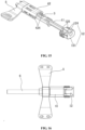
- the invention provides a manually-retractable intravenous infusion needle assembly, including: a needle holder 1, a needle tube 2, a built-in slidable sheath 3 and a protective casing 4, where the needle holder 1 includes a tubular portion 11 and a tailstock portion 12; the tubular portion 11 has a hollow and cylindrical, and is configured for the arrangement of the needle tube 2; the tailstock portion 12 is larger than the tubular portion in diameter, and is configured to connect a delivery tube; a front end of the needle tube extends forward and a rear end of the needle tube is mounted inside the tubular portion 11; the tubular portion 11 is detachably mounted in the built-in slidable sheath 3 and can slide back and forth; the tailstock portion 12 is always located outside a rear end of the built-in slidable sheath 3; the protective casing 4 is a long, through and hollow casing; the built-in slidable sheath 3 is mounted in the protective casing 4
- a first locking structure is provided between the tubular portion 11 and the built-in slidable sheath 3 to lock the tubular portion 11; a second locking structure is provided between the built-in slidable sheath 3 and the protective casing 4 to lock the built-in slidable sheath 3; and a third locking structure is provided between the needle holder 1 and the protective casing 4 to lock the needle holder 1.
- the needle holder 1 When the third locking structure is unlocked, the needle holder 1 is pulled backward to allow the tubular portion 11 to move to a locking position of the built-in slidable sheath 3 such that the tubular portion 11 is locked; when the needle holder 1 is continuously pulled backward, the built-in slidable sheath 3 is driven to move to a locking position of the protective casing 4 to be locked, and in this case, the needle tube 2 is completely covered by the protective casing 4 and a tip of the needle does not exceed the protective casing 4.
- the first locking structure includes a first positioning member and a first locking member.
- the first positioning member is provided at a front end of an outer wall of the tubular portion 11 and includes a sliding block 13.
- the built-in slidable sheath 3 having a C-shaped cross-section is through and elongated and an inner wall of the built-in slidable sheath 3 is provided with the first locking member.
- the first locking member includes a slotted hole 31 and a first elastic arm 32, where the slotted hole 31 is axially provided along the built-in slidable sheath 3 and is located on a central line of the built-in slidable sheath 3 along a width direction; and the first elastic arm 32 is provided at a rear section of the slotted hole 31.
- a rear-end through hole 311 with a gradually narrowing width is provided at a rear end of the slotted hole 31, and the rear-end through hole 311 is bent and extends toward a front end of the slotted hole 31 to form a fishhook-like through hole 312, providing the first elastic arm 32 in the rear-end through hole 311.
- the sliding block 13 is limited to slide within the slotted hole 31, and when the sliding block 13 is moved along the slotted hole 31 to the rear end of the slotted hole 31, the first elastic arm 32 is driven by the sliding block 13 to generate elastic deformation to allow the sliding block 13 to pass through; and when the sliding block 13 arrives at the rear end of the slotted hole 31, the first elastic arm 32 recovers to a normal state such that the sliding block 13 is locked in an axial direction of the built-in slidable sheath 3 and fails to slide reversely.
- a rear end of the built-in slidable sheath 3 will be driven to slide out of the protective casing 4 in the case of continuously pulling the tailstock portion 12 backward.
- the first positioning member further includes two side sliding blocks 14, which are symmetrically provided on two sides of the sliding block 13.
- the first locking member further includes two first chutes 33, which are axially provided along the built-in slidable sheath 3 and are symmetrically provided on two sides of the slotted hole 31.
- the two side sliding blocks 14 are respectively limited to slide within the two first chutes 33.
- the movement of the tubular portion 11 along a radial direction will be limited such that the tubular portion 11 fails to slip out of the built-in slidable sheath 3 in the radial direction, enabling more stable assembly between the tubular portion 11 and the built-in slidable sheath 3.
- the second locking structure includes a second positioning member and a second locking member.
- the second positioning member is provided on the built-in slidable sheath 3, and includes two bumps 34, where the two bumps 34 are respectively provided on two axial sections of the built-in slidable sheath 3.
- the protective casing 4 consists of an upper casing 41 and a lower casing 42, where the upper casing 41 is buckled with the lower casing 42.
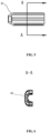
- the cross sections of the upper casing 41 and the lower casing 42 are approximately U-shaped.
- the second locking member is provided on an inner wall of the lower casing 42, and includes two second chutes (absent in the figures) and two second elastic arms 421.
- the two second chutes are symmetrically provided along the axial direction of the lower casing 42.
- the two second elastic arms 421 are respectively provided at rear sections of the two second chutes.
- the built-in slidable sheath 3 is mounted inside the upper casing 41, and two axial sections of the built-in slidable sheath 3 fit the inner wall of the lower casing 42.
- the two bumps 34 are respectively limited to slide within the two second chutes.
- the two second elastic arms 421 are respectively driven by the two bumps 34 to generate elastic deformation to allow the two bumps 34 to pass through; and when the two bumps respectively arrive at the rear ends of the two second chutes, the two second elastic arms 421 recover to a normal state such that the two bumps are locked and fails to slide reversely.
- the needle holder 1 is locked with the protective casing 4 in a side locking manner.
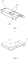
- the third locking structure includes a third positioning member and a third locking member. As shown in Fig. 7 , the third positioning member is provided on an outer wall of the lower casing 42, and is a triangular projection 422. As shown in Figs. 2 , 9 and 10 , the third locking member is provided on the tailstock portion 12.
- the tailstock portion 12 includes a tailstock body 121 and an assembling member 122, where the tailstock body 121 is connected to the tubular portion; a side of the tailstock body 121 is connected to the assembling member 122; the assembling member 122 is parallel to a center axis of the tubular portion 11 and clings to an outer wall of the protective casing 4; and the assembling member 122 is capable of being pulled to move from a side.
- the third locking member is provided on the assembling member 122, and is a triangular recess 123.
- the assembling member 122 includes a limiting portion 1221 and a rod portion 1222, where two ends of the limiting portion 1221 are respectively connected to the tailstock body 121 and the rod portion 1222.
- the rod portion 1222 is a free end, and the recess 123 is provided on the limiting portion 1221.
- the projection 422 is stuck by the recess 123, the tailstock portion 12 is locked to the protective casing 4; the front end of the built-in slidable sheath 3 is limited by the inner wall of the protective casing 4; and the rear end of the built-in slidable sheath 3 is limited by the tailstock portion 12.
- the assembling member 122 is pulled from the side, the projection 422 is unlocked from the recess 123, and the tailstock proportion 12 of the needle holder 1 is unlocked from the protective casing 4 and can be pulled backward.
- the intravenous infusion needle assembly further includes a wing 5, which is sleeved on the assembling member 122.
- the wing 5 When the wing 5 is pulled from a side, the assembling member 122 is pulled synchronously to move.
- the wing 5 includes a shaft sleeve 51 and a wing blade 52 connected to each other, where the shaft sleeve 51 is rotatably sleeved on the rod portion 1222 of the assembling member 122.
- the wing 5 is made of an elastic plastic.
- a surface of the wing blade 52 may be provided with an anti-slip structure such as granular protrusions and patterns to prevent slipping, which avoids the rotation of the needle tube 2 in the blood vessel, reducing the occurrence of damage to the blood vessel and phlebitis in patients who frequently undergo infusion.
- an anti-slip structure such as granular protrusions and patterns to prevent slipping, which avoids the rotation of the needle tube 2 in the blood vessel, reducing the occurrence of damage to the blood vessel and phlebitis in patients who frequently undergo infusion.
- the tubular portion 11, the built-in slidable sheath 3 and the protective casing 4 are compatible with each other in length such that the tubular portion 11 is accommodated in the built-in slidable sheath 3 and the built-in slidable sheath 3 is accommodated in the protective casing 4.
- a maximum vertical distance between the needle tube 2 and the outer wall of the lower protective casing 42 is 1.2 mm.
- the built-in slidable sheath is designed as elongated and through and to have a C-shaped cross section to minimize the vertical distance between the central axis of the needle tube 2 and a bottom of the needle holder 1, which avoids the formation of a large oblique angle between the needle tube 2 and a base of the needle tube 2, preventing the blood vessel from being stabbed by the needle.
- the protective casing 4 can be disassembled into the upper casing 41 and the lower casing 42, which is favorable for the mould-opening production.
- the built-in slidable sheath 3 is mounted inside the upper casing 41 and the two axial sections of the built-in slidable sheath 3 fit the inner wall of the lower casing 42, enabling the maximum distance between the axis of the needle tube 2 and the outer wall of the protective casing 42 to be no more than 1.5 mm.
- the manually-retractable intravenous infusion needle assembly provided herein is assembled as follows.
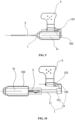
- the intravenous infusion needle assembly provided herein is substantially the same with the conventional infusion needle assembly in the operation, and the difference merely exists in that when the needle is pulled out, it is required to press the protective casing 4 by one hand, and the wing 5 on the assembling member 122 is held by the other hand and pulled outward gently such that the third locking member on the assembling member 122 is unlocked from the third positioning member on the lower casing 42; when the wing blade 52 is continuously pulled backward, the needle holder 1 is pulled out of the built-in slidable sheath 3 to a locking position to be locked, and the built-in slidable sheath 3 is driven to be pulled out of the protective casing 4 to a locking position to be locked.
- the needle holder 1 and the built-in slidable sheath 3 both fail to move back and forth, and the needle tube 2 is completely retracted to the protective casing 4 such that the needle tube 2 is pulled out of the patient.
- the third locking structure adopts a manner in which the needle holder 1 is locked with the front end of the protective casing 4.
- the third locking structure includes a third positioning member and a third locking member.
- the third positioning member is provided at the front end of the outer wall of the tubular portion 11, and includes two side sliding blocks 14 which are symmetrically arranged. It should be noted that the two side sliding blocks 14 of the third positioning member are actually the two side sliding blocks 14 of the first positioning member.
- Fig. 2 the third positioning member is provided at the front end of the outer wall of the tubular portion 11, and includes two side sliding blocks 14 which are symmetrically arranged. It should be noted that the two side sliding blocks 14 of the third positioning member are actually the two side sliding blocks 14 of the first positioning member.
- the third locking member is provided at the front end of the inner wall of the lower casing 42, and includes two elastically-deformable bevel bumps 423 which are symmetrically arranged.
- the tubular portion 11 is locked in the protective casing 4 and the built-in slidable sheath 3 is simultaneously locked by the tailstock portion 12.
- the two side sliding blocks 14 respectively push the two bevel bumps 423 to generate elastic deformation such that the two side sliding blocks 14 are allowed to slide through the two bevel bumps 423 and the needle holder 1 can be pulled backward to be out of the protective casing 4.
- the intravenous infusion needle assembly further includes a wing 5, which is sleeved on the tailstock portion 12.
- the wing 5 can be a single wing or a double wing, and only the double wing is illustrate herein. Two wings of the double wing are symmetrically provided and can be overlapped after folded, which can avoid the rotation of the needle tube 2 in the blood vessel, reducing the occurrence of blood vessel injury and phlebitis in patients who frequently undergo infusion.
- the tailstock portion 12 is pulled synchronously.
- the maximum vertical distance between the needle tube 2 and the outer peripheral surface of the lower casing 42 is 1.3 mm.
- the intravenous infusion needle assembly provided herein is assembled as follows.
- the intravenous infusion needle assembly provided herein is exactly the same with the conventional infusion needle assembly in the operation.
- the needle is pulled out, it is required to press the protective casing 4 by one hand, and the wing 5 is held by the other hand and pulled backward such that the two side sliding blocks 14 on the front end of the outer wall of the tubular portion 11 respectively press the bevels of the two bevel bumps 423 to generate elastic deformation, which causes that the two side sliding blocks 14 are respectively disengaged from the two bevel bumps 423.
- the needle holder 1 When the wing 5 is continuously pulled backward, the needle holder 1 is pulled out of the built-in slidable sheath 3 to a locking position to be locked, and the built-in slidable sheath 3 is driven to be pulled out of the protective casing 4 to a locking position to be locked. At this time, the needle holder 1 and the built-in slidable sheath 3 both fail to move back and forth, and the needle tube 2 is completely retracted to the protective casing 4 such that the needle tube 2 is pulled out of the patient.
- the third locking structure in this embodiment adopts a manner in which the needle holder 1 is locked with the rear end of the protective casing 4.
- the third locking structure includes a third positioning member and a third locking member.
- the third positioning member is provided on the tailstock portion 12, where the tailstock portion 12 includes a tailstock body 121 and two pressing members 124.
- the tailstock body 121 is connected to the tubular portion 11, and the two pressing members 124 are respectively connected to two sides of the tailstock body 121.
- the two pressing members 124 both are parallel to the central axis of the tubular portion 11, and can be pressed toward each other.
- the third positioning member includes two hooks 125, which are respectively provided at the front ends of the two pressing members 124.
- the rear end of the lower casing 42 is provided with the third locking member, which includes two slots 424, where the two slots 424 are respectively provided at two sides of the rear end of the protective casing 4.
- the tailstock portion 12 is locked to the rear end of the protective casing 4; the front end of the built-in slidable sheath 3 is limited by the inner wall of the protective casing 4; and the rear end of the built-in slidable sheath 3 is limited by the tailstock portion 12.
- the two hooks 125 are respectively unlocked from the two slots such that the tailstock portion 12 is unlocked from the rear end of the protective casing 4 and can be pulled backward.
- the intravenous infusion needle assembly provided herein further includes a wing 5.
- the wing 5 is a sing wing and is sleeved on the protective casing 4.
- the intravenous infusion needle assembly provided herein is assembled as follows.
- the infusion needle assembly provided herein is completely the same with the conventional infusion needle assembly in the operation, and an operator can hold the wing 5 to stick the needle.
- the needle is pulled out, it is required to press the protective casing 4 by one hand, and press the two pressing members 124 of the tailstock portion 12 at both sides with the other hand such that the third positioning member on the tailstock portion 12 is unlocked from the third locking member at the rear end of the lower casing 42. Then the tailstock portion 12 is pulled backward to allow the needle holder 1 to be pulled out of the built-in slidable sheath 3 to a locking position to be locked.
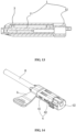
- the built-in slidable sheath 3 is driven to be pulled out of the protective casing 4 to a locking position to be locked. As shown in Fig. 15 , at this time, the needle holder 1 and the built-in slidable sheath 3 both fail to move back and forth, and the needle tube 2 is completely retracted to the protective casing 4 such that the needle tube 2 is pulled out of the patient.
- the wing 5 employed herein is a double wing.
- Two wings of the double wing are symmetrically arranged and can be overlapped after folded in half, which can avoid the rotation of the needle tube 2 in the blood vessel, reducing the occurrence of damage to the blood vessel and phlebitis in patients who frequently undergo infusion.
- the assembling process and the operation method are consistent with those described in Example 3.
- the convexity-concavity of the positioning member and the locking member can be interchanged, that is, the positioning member can be a concave portion, and the locking member can be a convex portion, as long as the concave and convex portions can be locked with each other.
Landscapes
- Health & Medical Sciences (AREA)
- Life Sciences & Earth Sciences (AREA)
- Hematology (AREA)
- Anesthesiology (AREA)
- Biomedical Technology (AREA)
- Heart & Thoracic Surgery (AREA)
- Engineering & Computer Science (AREA)
- Animal Behavior & Ethology (AREA)
- General Health & Medical Sciences (AREA)
- Public Health (AREA)
- Veterinary Medicine (AREA)
- Vascular Medicine (AREA)
- Biophysics (AREA)
- Pulmonology (AREA)
- Infusion, Injection, And Reservoir Apparatuses (AREA)
Claims (12)
- Manuell einziehbare intravenöse Infusionsnadelanordnung, umfassend:einen Nadelhalter (1);ein Nadelrohr (2);eine eingebaute verschiebbare Hülse (3); undein Schutzgehäuse (4);wobei:der Nadelhalter (1) einen rohrförmigen Abschnitt (11) und einen Reitstockabschnitt (12) umfasst; der rohrförmige Abschnitt (11) und der Reitstockabschnitt (12) vorne und hinten angeordnet und miteinander verbunden sind; der rohrförmige Abschnitt (11) für die Anordnung des Nadelrohrs (2) konfiguriert ist; der Reitstockabschnitt (12) für den Anschluss eines Zuführungsrohrs konfiguriert ist;die eingebaute verschiebbare Hülse (3) ist durchgehend und länglich ist und einen C-förmigen Querschnitt aufweist;das Schutzgehäuse (4) ein längliches, durchgehendes und hohles Gehäuse ist;ein hinteres Ende des Nadelrohrs (2) im Inneren des rohrförmigen Abschnitts (11) installiert ist; der rohrförmige Abschnitt (11) in der eingebauten verschiebbaren Hülse (3) installiert ist und hin und her gleiten kann; der Reitstockabschnitt (12) außerhalb eines hinteren Endes der eingebauten verschiebbaren Hülse (3) vorgesehen ist; die eingebaute verschiebbare Hülse (3) in dem Schutzgehäuse (4) installiert ist und hin und her gleiten kann; der Nadelhalter (1) an dem Schutzgehäuse (4) verriegelt werden kann;eine erste Verriegelungsstruktur zwischen dem Nadelhalter (1) und der eingebauten verschiebbaren Hülse (3) vorgesehen ist, um den Nadelhalter (1) zu verriegeln; eine zweite Verriegelungsstruktur zwischen der eingebauten verschiebbaren Hülse (3) und dem Schutzgehäuse (4) vorgesehen ist, um die eingebaute verschiebbare Hülse (3) zu verriegeln; und eine dritte Verriegelungsstruktur zwischen dem Nadelhalter (1) und dem Schutzgehäuse (4) vorgesehen ist, um den Nadelhalter (1) zu verriegeln;die erste Verriegelungsstruktur ein erstes Positionierungselement und ein erstes Verriegelungselement umfasst; wobei das erste Positionierungselement an einer Außenwand des rohrförmigen Abschnitts (11) vorgesehen ist und das erste Verriegelungselement an einer Innenwand der eingebauten verschiebbaren Hülse (3) vorgesehen ist;die zweite Verriegelungsstruktur ein zweites Positionierungselement und ein zweites Verriegelungselement umfasst; wobei das zweite Positionierungselement an der eingebauten verschiebbaren Hülse (3) vorgesehen ist und das zweite Verriegelungselement an einer Innenwand des Schutzgehäuses (4) vorgesehen ist;das zweite Positionierungselement zwei Höcker (34) umfasst, wobei die beiden Höcker (34) jeweils an zwei axialen Abschnitten der eingebauten verschiebbaren Hülse (3) vorgesehen sind;das zweite Verriegelungselement zwei zweite Rutschen und zwei zweite elastische Arme (421) umfasst; wobei die beiden zweiten Rutschen axial und symmetrisch entlang dem Schutzgehäuse (4) vorgesehen sind; die beiden zweiten elastischen Arme (421) jeweils an hinteren Abschnitten der beiden zweiten Rutschen vorgesehen sind;die beiden Höcker (34) jeweils darauf beschränkt sind, innerhalb der beiden zweiten Rutschen zu gleiten; wobei, wenn die beiden Höcker (34) jeweils entlang den beiden zweiten Rutschen zu den hinteren Enden der beiden zweiten Rutschen bewegt werden, die beiden zweiten elastischen Arme (421) jeweils von den beiden Höckern (34) dazu angetrieben werden, eine elastische Verformung zu erzeugen, um den beiden Höckern (34) den Durchgang zu ermöglichen; und wobei, wenn die beiden Höcker (34) jeweils an den hinteren Enden der beiden zweiten Rutschen ankommen, die beiden zweiten elastischen Arme (421) in einen normalen Zustand zurückkehren, so dass die beiden Höcker (34) verriegelt sind und nicht rückwärts gleiten können; undwobei, wenn die dritte Verriegelungsstruktur entriegelt ist, der Nadelhalter (1) nach hinten gezogen wird, um zu ermöglichen, dass sich der rohrförmige Abschnitt (11) in eine Verriegelungsposition der eingebauten verschiebbaren Hülse (3) bewegt, so dass das erste Positionierungselement durch das erste Verriegelungselement verriegelt wird, um zu ermöglichen, dass der rohrförmige Abschnitt (11) verriegelt ist und nicht von der eingebauten verschiebbaren Hülse (3) abrutscht; und wobei, wenn der Nadelhalter (1) kontinuierlich nach hinten gezogen wird, die eingebaute verschiebbare Hülse (3) dazu angetrieben wird, sich in eine Verriegelungsposition des Schutzgehäuses (4) zu bewegen, so dass das zweite Positionierungselement durch das zweite Verriegelungselement verriegelt wird, um zu ermöglichen, dass die eingebaute verschiebbare Hülse (3) nicht von dem Schutzgehäuse (4) abrutscht, und wobei in diesem Fall das Nadelrohr (2) vollständig von dem Schutzgehäuse (4) bedeckt ist und eine Spitze des Nadelrohrs nicht über das Schutzgehäuse (4) hinausragt.
- Intravenöse Infusionsnadelanordnung nach Anspruch 1, dadurch gekennzeichnet, dass das erste Positionierungselement einen Gleitblock (13) umfasst; wobei das erste Verriegelungselement ein schlitzförmiges Loch (31) und einen ersten elastischen Arm (32) umfasst; und wobei das schlitzförmige Loch (31) axial entlang der eingebauten verschiebbaren Hülse (3) vorgesehen ist; und wobei der erste elastische Arm (32) an einem hinteren Abschnitt des schlitzförmigen Lochs (31) vorgesehen ist; und wobei der Gleitblock (13) darauf beschränkt ist, innerhalb des schlitzförmigen Lochs (31) zu gleiten; und wobei, wenn der Gleitblock (13) entlang dem schlitzförmigen Lochs (31) zu einem hinteren Ende des schlitzförmigen Lochs (31) bewegt wird, der erste elastische Arm (32) durch den Gleitblock (13) dazu angetrieben wird, eine elastische Verformung zu erzeugen, damit der Gleitblock (13) durchlaufen kann; und wobei, wenn der Gleitblock (13) am hinteren Ende des schlitzförmigen Lochs (31) ankommt, der erste elastische Arm (32) in einen normalen Zustand zurückkehrt, so dass der Gleitblock (13) verriegelt ist und nicht rückwärts gleiten kann.
- Intravenöse Infusionsnadelanordnung nach Anspruch 2, dadurch gekennzeichnet, dass das erste Positionierungselement weiterhin zwei seitliche Gleitblöcke (14) umfasst, wobei die beiden seitlichen Gleitblöcke (14) jeweils an zwei Seiten des Gleitblocks (13) vorgesehen sind;
das erste Verriegelungselement weiterhin zwei erste Rutschen (33) umfasst; wobei die beiden ersten Rutschen (33) jeweils axial an zwei Seiten des schlitzförmigen Lochs (31) entlang der eingebauten verschiebbaren Hülse (3) vorgesehen sind; und wobei die beiden seitlichen Gleitblöcke (14) jeweils so begrenzt sind, dass sie innerhalb der beiden ersten Rutschen (33) gleiten, so dass der rohrförmige Abschnitt (11) nicht radial von der eingebauten verschiebbaren Hülse (3) abrutscht. - Intravenöse Infusionsnadelanordnung nach Anspruch 1, dadurch gekennzeichnet, dass die dritte Verriegelungsstruktur ein drittes Verriegelungselement und ein drittes Positionierungselement umfasst, wobei das dritte Verriegelungselement an dem Reitstockabschnitt (12) vorgesehen ist und das dritte Positionierungselement an einer Außenwand des Schutzgehäuses (4) vorgesehen ist; und wobei, wenn das dritte Verriegelungselement an dem dritten Positionierungselement verriegelt ist, der Reitstockabschnitt (12) an dem Schutzgehäuse (4) verriegelt ist, ein vorderes Ende der eingebauten verschiebbaren Hülse (3) durch eine Innenwand des Schutzgehäuses (4) begrenzt ist und ein hinteres Ende der eingebauten verschiebbaren Hülse (3) durch den Reitstockabschnitt (12) begrenzt ist; und wobei, wenn das dritte Verriegelungselement von dem dritten Positionierungselement entriegelt ist, der Nadelhalter (1) nach hinten gezogen werden kann.
- Intravenöse Infusionsnadelanordnung nach Anspruch 4, dadurch gekennzeichnet, dass der Reitstockabschnitt (12) einen Reitstockkörper (121) und ein Montageelement (122) umfasst, wobei der Reitstockkörper (121) mit dem rohrförmigen Abschnitt (11) verbunden ist; und wobei eine Seitenfläche des Reitstockkörpers (121) mit dem Montageelement (122) verbunden ist; und wobei das Montageelement (122) parallel zu einer Mittelachse des rohrförmigen Abschnitts (11) ausgerichtet ist und an der Außenwand des Schutzgehäuses (4) anhaftet; und wobei das Montageelement (122) gezogen werden kann, um sich von einer Seitenfläche zu bewegen;
und wobei das dritte Verriegelungselement an dem Montageelement (122) vorgesehen ist; und wobei das dritte Verriegelungselement eine Aussparung (123) umfasst und das dritte Positionierungselement einen Vorsprung (422) umfasst; und wobei, wenn das Montageelement (122) gezogen wird, um sich von der Seitenfläche zu bewegen, die Aussparung (123) von dem Vorsprung (422) entriegelt wird. - Intravenöse Infusionsnadelanordnung nach Anspruch 1, dadurch gekennzeichnet, dass die dritte Verriegelungsstruktur ein drittes Positionierungselement und ein drittes Verriegelungselement umfasst, wobei das dritte Positionierungselement an dem rohrförmigen Abschnitt (11) vorgesehen ist und das dritte Verriegelungselement an einem vorderen Ende einer Innenwand des Schutzgehäuses (4) vorgesehen ist;und wobei, wenn das dritte Positionierungselement durch das dritte Verriegelungselement verriegelt ist, der rohrförmige Abschnitt (11) innerhalb des Schutzgehäuses (4) verriegelt ist, und wobei ein vorderes Ende der eingebauten verschiebbaren Hülse (3) durch eine Innenwand des Schutzgehäuses (4) begrenzt ist und ein hinteres Ende der eingebauten verschiebbaren Hülse (3) durch den Reitstockabschnitt (12) begrenzt ist; und wobei, wenn das dritte Positionierungselement von dem dritten Verriegelungselement entriegelt ist, der rohrförmige Abschnitt (11) aus der eingebauten verschiebbaren Hülse (3) herausgezogen werden kann;und wobei das dritte Positionierungselement zwei seitliche Gleitblöcke (14) umfasst, und wobei die beiden seitlichen Gleitblöcke (14) symmetrisch an einem vorderen Ende einer Außenwand des rohrförmigen Abschnitts (11) vorgesehen sind;und wobei das dritte Verriegelungselement zwei elastisch verformbare schräge Höcker (423) umfasst; und wobei die schrägen Höcker (423) symmetrisch an einem vorderen Ende einer Innenwand des Schutzgehäuses (4) vorgesehen sind;und wobei, wenn die beiden seitlichen Gleitblöcke (14) jeweils durch die beiden schrägen Höcker (423) verriegelt werden, der rohrförmige Abschnitt (11) innerhalb des Schutzgehäuses (4) verriegelt wird und die eingebaute verschiebbare Hülse (3) gleichzeitig durch den Reitstockabschnitt (12) begrenzt wird; und wobei, wenn der rohrförmige Abschnitt (11) nach hinten gezogen wird, die beiden seitlichen Gleitblöcke (14) jeweils die beiden schrägen Höcker (423) dazu antreiben, eine elastische Verformung zu erzeugen, so dass die beiden seitlichen Gleitblöcke (14) jeweils durch die beiden schrägen Höcker (423) gleiten und der Nadelhalter (1) nach hinten aus dem Schutzgehäuse (4) gezogen wird.
- Intravenöse Infusionsnadelanordnung nach Anspruch 6, umfassend weiterhin einen Flügel (5), wobei der Flügel (5) an den Reitstockabschnitt (12) aufgesetzt ist; und wobei der Flügel (5) ein Einzelflügel oder ein Doppelflügel ist; und wobei zwei Flügel des Doppelflügels symmetrisch vorgesehen sind und sich nach dem Falten überlappen; und wobei, wenn der Flügel (5) gehalten wird, um nach hinten gezogen zu werden, der Nadelhalter (1) synchron gezogen wird.
- Intravenöse Infusionsnadelanordnung nach Anspruch 1, dadurch gekennzeichnet, dass die dritte Verriegelungsstruktur ein drittes Positionierungselement und ein drittes Verriegelungselement umfasst, wobei das dritte Positionierungselement an dem Reitstockabschnitt (12) vorgesehen ist und das dritte Verriegelungselement an einem hinteren Ende des Schutzgehäuses (4) vorgesehen ist;
und wobei, wenn das dritte Positionierungselement durch das dritte Verriegelungselement verriegelt ist, der Reitstockabschnitt (12) am hinteren Ende des Schutzgehäuses (4) verriegelt ist, und wobei ein vorderes Ende der eingebauten verschiebbaren Hülse (3) durch eine Innenwand des Schutzgehäuses (4) begrenzt ist und ein hinteres Ende der eingebauten verschiebbaren Hülse (3) durch den Reitstockabschnitt (12) begrenzt ist; und wobei, wenn das dritte Positionierungselement von dem dritten Verriegelungselement entriegelt ist, der Reitstockabschnitt (12) nach hinten gezogen werden kann, um sich zu bewegen. - Intravenöse Infusionsnadelanordnung nach Anspruch 8, dadurch gekennzeichnet, dass der Reitstockabschnitt (12) einen Reitstockkörper (121) und zwei Druckelemente (124) umfasst; wobei der Reitstockkörper (121) mit dem rohrförmigen Abschnitt (11) verbunden ist; und wobei die beiden Druckelemente (124) jeweils mit zwei Seiten des Reitstockkörpers (121) verbunden sind; und wobei die beiden Druckelemente (124) jeweils parallel zu einer Mittelachse des rohrförmigen Abschnitts (11) ausgerichtet sind; und wobei die beiden Druckelemente (124) in der Lage sind, entgegengesetzt gedrückt zu werden;das dritte Positionierungselement zwei Haken (125) umfasst, und wobei die beiden Haken (125) jeweils an den vorderen Enden der beiden Druckelemente (124) vorgesehen sind;das dritte Verriegelungselement zwei Schlitze (424) umfasst, wobei die beiden Schlitze (424) jeweils an zwei Seiten des hinteren Endes des Schutzgehäuses (4) vorgesehen sind; unddie beiden Haken (125) jeweils von den beiden Schlitzen (424) entriegelt sind, wenn die beiden Druckelemente (124) so gehalten werden, dass sie gegeneinander gedrückt werden.
- Intravenöse Infusionsnadelanordnung nach Anspruch 9, umfassend weiterhin einen Flügel (5); wobei der Flügel (5) an dem Schutzgehäuse (4) aufgesetzt ist; und wobei der Flügel ein Einzelflügel oder ein Doppelflügel ist; und wobei zwei Flügel des Doppelflügels symmetrisch vorgesehen sind und sich nach dem Falten überlappen.
- Intravenöse Infusionsnadelanordnung nach einem der Ansprüche 1 bis 10, dadurch gekennzeichnet, dass das Schutzgehäuse (4) aus einem oberen Gehäuse (41) und einem unteren Gehäuse (42) besteht, wobei das obere Gehäuse (41) mit dem unteren Gehäuse (42) geschnallt ist; und wobei die eingebaute verschiebbare Hülse (3) innerhalb des oberen Gehäuses (41) installiert ist; und wobei zwei axiale Abschnitte der eingebauten verschiebbaren Hülse (3) in eine Innenwand des unteren Gehäuses (42) passen.
- Intravenöse Infusionsnadelanordnung nach Anspruch 11, dadurch gekennzeichnet, dass ein maximaler vertikaler Abstand zwischen dem Nadelrohr (2) und einer Außenwand des unteren Gehäuses (42) gleich oder kleiner als 1,5 mm ist.
Applications Claiming Priority (3)
| Application Number | Priority Date | Filing Date | Title |
|---|---|---|---|
| CN201710288265 | 2017-04-27 | ||
| CN201710432400.3A CN107281586A (zh) | 2017-04-27 | 2017-06-09 | 一种针头手动回缩式静脉输液针 |
| PCT/CN2018/090524 WO2018224045A1 (zh) | 2017-04-27 | 2018-06-08 | 一种针头手动回缩式静脉输液针 |
Publications (4)
| Publication Number | Publication Date |
|---|---|
| EP3636299A1 EP3636299A1 (de) | 2020-04-15 |
| EP3636299A4 EP3636299A4 (de) | 2020-10-21 |
| EP3636299B1 true EP3636299B1 (de) | 2023-06-07 |
| EP3636299C0 EP3636299C0 (de) | 2023-06-07 |
Family
ID=60097848
Family Applications (1)
| Application Number | Title | Priority Date | Filing Date |
|---|---|---|---|
| EP18812646.0A Active EP3636299B1 (de) | 2017-04-27 | 2018-06-08 | Nadel für intravenöse infusion mit manuellem nadelrückzug |
Country Status (12)
| Country | Link |
|---|---|
| US (1) | US11338085B2 (de) |
| EP (1) | EP3636299B1 (de) |
| JP (1) | JP6993007B2 (de) |
| KR (1) | KR102433741B1 (de) |
| CN (3) | CN107281586A (de) |
| AU (1) | AU2018279677B2 (de) |
| CA (1) | CA3066506C (de) |
| ES (1) | ES2953809T3 (de) |
| PH (1) | PH12019502779A1 (de) |
| RU (1) | RU2744547C1 (de) |
| SG (1) | SG11201911847XA (de) |
| WO (1) | WO2018224045A1 (de) |
Families Citing this family (5)
| Publication number | Priority date | Publication date | Assignee | Title |
|---|---|---|---|---|
| CN107281586A (zh) | 2017-04-27 | 2017-10-24 | 王祖扬 | 一种针头手动回缩式静脉输液针 |
| CN107198531A (zh) * | 2017-04-27 | 2017-09-26 | 王祖扬 | 一种针头自动回缩式采血针 |
| CN107638183B (zh) * | 2017-10-30 | 2023-12-26 | 广东龙心医疗器械有限公司 | 具有可缩回针的流体输送装置 |
| CN109248354B (zh) * | 2018-09-25 | 2023-12-15 | 重庆医药集团威逊医疗科技有限公司 | 一种防针刺伤安全留置针 |
| CN110227199A (zh) * | 2019-05-21 | 2019-09-13 | 李豫 | 一种新型无金属漏斗留置针 |
Citations (1)
| Publication number | Priority date | Publication date | Assignee | Title |
|---|---|---|---|---|
| CN104288866A (zh) * | 2014-10-24 | 2015-01-21 | 上海金塔医用器材有限公司 | 一次性使用防针刺静脉输液穿刺针 |
Family Cites Families (15)
| Publication number | Priority date | Publication date | Assignee | Title |
|---|---|---|---|---|
| NL9002552A (nl) * | 1990-09-05 | 1992-04-01 | Advanced Protective Injection | Infusie- of transfusienaaldsamenstel. |
| CA2065895A1 (en) * | 1992-04-13 | 1993-10-14 | Jean M. Bonaldo | Retractable intravenous needle assembly |
| US5772636A (en) * | 1996-12-02 | 1998-06-30 | Becton Dickinson And Company | Catheter assembly with interlocking telescoping needle shield |
| ES2209439T3 (es) * | 1998-07-31 | 2004-06-16 | Mdc Investment Holding, Inc. | Dispositivo medico con aguja retractil. |
| US6210371B1 (en) * | 1999-03-30 | 2001-04-03 | Retractable Technologies, Inc. | Winged I.V. set |
| JP2001259029A (ja) * | 2000-03-21 | 2001-09-25 | Medikit Kk | 安全留置針 |
| US7060053B2 (en) * | 2002-02-28 | 2006-06-13 | Medikit Co., Ltd. | Safety indwelling syringe |
| EP1374934A1 (de) * | 2002-06-25 | 2004-01-02 | Sergio Restelli | Kanüle mit Flügeln mit verbesserter Sicherheit |
| US20040236287A1 (en) * | 2003-05-23 | 2004-11-25 | Becton Dickinson & Company | Forward shielding medical needle device |
| TWI308874B (en) * | 2004-02-26 | 2009-04-21 | Nipro Corp | Safe indwelling needle |
| CN101954133B (zh) * | 2009-07-14 | 2012-12-05 | 美昕医疗器械(昆山)有限公司 | 安全型静脉输液针 |
| CN205055046U (zh) * | 2015-08-27 | 2016-03-02 | 王祖扬 | 一种安全式输液针 |
| JP6336008B2 (ja) * | 2015-11-23 | 2018-06-06 | ジェムティア メディカル (シャンハイ) インコーポレイテッド | 針刺し装置 |
| CN206198391U (zh) * | 2016-08-16 | 2017-05-31 | 上海金塔医用器材有限公司 | 防针刺结构及防针刺静脉输液穿刺针 |
| CN107281586A (zh) * | 2017-04-27 | 2017-10-24 | 王祖扬 | 一种针头手动回缩式静脉输液针 |
-
2017
- 2017-06-09 CN CN201710432400.3A patent/CN107281586A/zh active Pending
-
2018
- 2018-06-08 WO PCT/CN2018/090524 patent/WO2018224045A1/zh not_active Ceased
- 2018-06-08 KR KR1020207000422A patent/KR102433741B1/ko active Active
- 2018-06-08 JP JP2019568060A patent/JP6993007B2/ja active Active
- 2018-06-08 CN CN201820889086.1U patent/CN209500430U/zh not_active Withdrawn - After Issue
- 2018-06-08 CN CN201810590298.4A patent/CN108939204B/zh active Active
- 2018-06-08 ES ES18812646T patent/ES2953809T3/es active Active
- 2018-06-08 EP EP18812646.0A patent/EP3636299B1/de active Active
- 2018-06-08 CA CA3066506A patent/CA3066506C/en active Active
- 2018-06-08 AU AU2018279677A patent/AU2018279677B2/en active Active
- 2018-06-08 RU RU2019144051A patent/RU2744547C1/ru active
- 2018-06-08 SG SG11201911847XA patent/SG11201911847XA/en unknown
-
2019
- 2019-12-09 US US16/708,160 patent/US11338085B2/en active Active
- 2019-12-10 PH PH12019502779A patent/PH12019502779A1/en unknown
Patent Citations (1)
| Publication number | Priority date | Publication date | Assignee | Title |
|---|---|---|---|---|
| CN104288866A (zh) * | 2014-10-24 | 2015-01-21 | 上海金塔医用器材有限公司 | 一次性使用防针刺静脉输液穿刺针 |
Also Published As
| Publication number | Publication date |
|---|---|
| US20200114070A1 (en) | 2020-04-16 |
| CA3066506A1 (en) | 2018-12-13 |
| AU2018279677A1 (en) | 2020-01-16 |
| SG11201911847XA (en) | 2020-01-30 |
| EP3636299C0 (de) | 2023-06-07 |
| RU2744547C1 (ru) | 2021-03-11 |
| EP3636299A4 (de) | 2020-10-21 |
| KR102433741B1 (ko) | 2022-08-18 |
| BR112019026051A2 (pt) | 2020-06-23 |
| CN209500430U (zh) | 2019-10-18 |
| PH12019502779A1 (en) | 2020-10-26 |
| JP6993007B2 (ja) | 2022-01-13 |
| AU2018279677B2 (en) | 2021-09-02 |
| CN108939204B (zh) | 2023-11-03 |
| US11338085B2 (en) | 2022-05-24 |
| CA3066506C (en) | 2023-11-07 |
| ES2953809T3 (es) | 2023-11-16 |
| JP2020522362A (ja) | 2020-07-30 |
| WO2018224045A1 (zh) | 2018-12-13 |
| EP3636299A1 (de) | 2020-04-15 |
| CN107281586A (zh) | 2017-10-24 |
| CN108939204A (zh) | 2018-12-07 |
| KR20200016947A (ko) | 2020-02-17 |
| BR112019026051A8 (pt) | 2022-10-04 |
Similar Documents
| Publication | Publication Date | Title |
|---|---|---|
| US11338085B2 (en) | Manually-retractable intravenous infusion needle assembly | |
| EP3636155B1 (de) | Blutabnahmenadel mit automatischem nadeleinzug | |
| EP2455127B1 (de) | Sicherer einweg-injektor mit austauschbarer und automatisch einziehbarer nadel | |
| CN107789040B (zh) | 一种具有限位结构的安全型医用套管针 | |
| CN104470440A (zh) | 具有伸缩保护套的针筒式真空采血器 | |
| CN206239824U (zh) | 一种一次性使用自动弹出式医用针 | |
| CN205055045U (zh) | 静脉留置针 | |
| CN211096659U (zh) | 一种安全弹射静脉针 | |
| CN204233533U (zh) | 一种安全型一次性头皮针 | |
| CN106390233A (zh) | 一种一次性使用自动弹出式医用针 | |
| CN221557120U (zh) | 透析留置针 | |
| BR112019026051B1 (pt) | Conjunto de agulha de infusão intravenosa manualmente retrátil | |
| CN213554493U (zh) | 一种胰岛素针头 | |
| CN211432944U (zh) | 一种防针刺采血针 | |
| CN208389096U (zh) | 一种针头手动回缩式静脉输液针 | |
| CN110624162A (zh) | 一种安全型针头装置 | |
| CN104353152A (zh) | 一种安全型一次性头皮针 | |
| US20020095109A1 (en) | Safety drop infusion/transfusion set capable of preventing recovered hypodermic needle from being pushed out | |
| CN107281587A (zh) | 一种针头安全回缩静脉输液针 |
Legal Events
| Date | Code | Title | Description |
|---|---|---|---|
| STAA | Information on the status of an ep patent application or granted ep patent |
Free format text: STATUS: THE INTERNATIONAL PUBLICATION HAS BEEN MADE |
|
| PUAI | Public reference made under article 153(3) epc to a published international application that has entered the european phase |
Free format text: ORIGINAL CODE: 0009012 |
|
| STAA | Information on the status of an ep patent application or granted ep patent |
Free format text: STATUS: REQUEST FOR EXAMINATION WAS MADE |
|
| 17P | Request for examination filed |
Effective date: 20191220 |
|
| AK | Designated contracting states |
Kind code of ref document: A1 Designated state(s): AL AT BE BG CH CY CZ DE DK EE ES FI FR GB GR HR HU IE IS IT LI LT LU LV MC MK MT NL NO PL PT RO RS SE SI SK SM TR |
|
| AX | Request for extension of the european patent |
Extension state: BA ME |
|
| DAV | Request for validation of the european patent (deleted) | ||
| DAX | Request for extension of the european patent (deleted) | ||
| A4 | Supplementary search report drawn up and despatched |
Effective date: 20200923 |
|
| RIC1 | Information provided on ipc code assigned before grant |
Ipc: A61M 25/06 20060101ALI20200917BHEP Ipc: A61M 5/158 20060101AFI20200917BHEP |
|
| GRAP | Despatch of communication of intention to grant a patent |
Free format text: ORIGINAL CODE: EPIDOSNIGR1 |
|
| STAA | Information on the status of an ep patent application or granted ep patent |
Free format text: STATUS: GRANT OF PATENT IS INTENDED |
|
| INTG | Intention to grant announced |
Effective date: 20220922 |
|
| GRAS | Grant fee paid |
Free format text: ORIGINAL CODE: EPIDOSNIGR3 |
|
| GRAA | (expected) grant |
Free format text: ORIGINAL CODE: 0009210 |
|
| STAA | Information on the status of an ep patent application or granted ep patent |
Free format text: STATUS: THE PATENT HAS BEEN GRANTED |
|
| AK | Designated contracting states |
Kind code of ref document: B1 Designated state(s): AL AT BE BG CH CY CZ DE DK EE ES FI FR GB GR HR HU IE IS IT LI LT LU LV MC MK MT NL NO PL PT RO RS SE SI SK SM TR |
|
| REG | Reference to a national code |
Ref country code: GB Ref legal event code: FG4D |
|
| REG | Reference to a national code |
Ref country code: CH Ref legal event code: EP Ref country code: AT Ref legal event code: REF Ref document number: 1573033 Country of ref document: AT Kind code of ref document: T Effective date: 20230615 Ref country code: DE Ref legal event code: R096 Ref document number: 602018051369 Country of ref document: DE |
|
| U01 | Request for unitary effect filed |
Effective date: 20230630 |
|
| U07 | Unitary effect registered |
Designated state(s): AT BE BG DE DK EE FI FR IT LT LU LV MT NL PT SE SI Effective date: 20230708 |
|
| U20 | Renewal fee for the european patent with unitary effect paid |
Year of fee payment: 6 Effective date: 20230720 |
|
| REG | Reference to a national code |
Ref country code: LT Ref legal event code: MG9D |
|
| PG25 | Lapsed in a contracting state [announced via postgrant information from national office to epo] |
Ref country code: NO Free format text: LAPSE BECAUSE OF FAILURE TO SUBMIT A TRANSLATION OF THE DESCRIPTION OR TO PAY THE FEE WITHIN THE PRESCRIBED TIME-LIMIT Effective date: 20230907 |
|
| REG | Reference to a national code |
Ref country code: ES Ref legal event code: FG2A Ref document number: 2953809 Country of ref document: ES Kind code of ref document: T3 Effective date: 20231116 |
|
| PG25 | Lapsed in a contracting state [announced via postgrant information from national office to epo] |
Ref country code: RS Free format text: LAPSE BECAUSE OF FAILURE TO SUBMIT A TRANSLATION OF THE DESCRIPTION OR TO PAY THE FEE WITHIN THE PRESCRIBED TIME-LIMIT Effective date: 20230607 Ref country code: HR Free format text: LAPSE BECAUSE OF FAILURE TO SUBMIT A TRANSLATION OF THE DESCRIPTION OR TO PAY THE FEE WITHIN THE PRESCRIBED TIME-LIMIT Effective date: 20230607 Ref country code: GR Free format text: LAPSE BECAUSE OF FAILURE TO SUBMIT A TRANSLATION OF THE DESCRIPTION OR TO PAY THE FEE WITHIN THE PRESCRIBED TIME-LIMIT Effective date: 20230908 |
|
| PG25 | Lapsed in a contracting state [announced via postgrant information from national office to epo] |
Ref country code: SK Free format text: LAPSE BECAUSE OF FAILURE TO SUBMIT A TRANSLATION OF THE DESCRIPTION OR TO PAY THE FEE WITHIN THE PRESCRIBED TIME-LIMIT Effective date: 20230607 |
|
| PG25 | Lapsed in a contracting state [announced via postgrant information from national office to epo] |
Ref country code: IS Free format text: LAPSE BECAUSE OF FAILURE TO SUBMIT A TRANSLATION OF THE DESCRIPTION OR TO PAY THE FEE WITHIN THE PRESCRIBED TIME-LIMIT Effective date: 20231007 |
|
| PG25 | Lapsed in a contracting state [announced via postgrant information from national office to epo] |
Ref country code: SM Free format text: LAPSE BECAUSE OF FAILURE TO SUBMIT A TRANSLATION OF THE DESCRIPTION OR TO PAY THE FEE WITHIN THE PRESCRIBED TIME-LIMIT Effective date: 20230607 Ref country code: SK Free format text: LAPSE BECAUSE OF FAILURE TO SUBMIT A TRANSLATION OF THE DESCRIPTION OR TO PAY THE FEE WITHIN THE PRESCRIBED TIME-LIMIT Effective date: 20230607 Ref country code: RO Free format text: LAPSE BECAUSE OF FAILURE TO SUBMIT A TRANSLATION OF THE DESCRIPTION OR TO PAY THE FEE WITHIN THE PRESCRIBED TIME-LIMIT Effective date: 20230607 Ref country code: IS Free format text: LAPSE BECAUSE OF FAILURE TO SUBMIT A TRANSLATION OF THE DESCRIPTION OR TO PAY THE FEE WITHIN THE PRESCRIBED TIME-LIMIT Effective date: 20231007 Ref country code: CZ Free format text: LAPSE BECAUSE OF FAILURE TO SUBMIT A TRANSLATION OF THE DESCRIPTION OR TO PAY THE FEE WITHIN THE PRESCRIBED TIME-LIMIT Effective date: 20230607 |
|
| PG25 | Lapsed in a contracting state [announced via postgrant information from national office to epo] |
Ref country code: PL Free format text: LAPSE BECAUSE OF FAILURE TO SUBMIT A TRANSLATION OF THE DESCRIPTION OR TO PAY THE FEE WITHIN THE PRESCRIBED TIME-LIMIT Effective date: 20230607 |
|
| REG | Reference to a national code |
Ref country code: DE Ref legal event code: R097 Ref document number: 602018051369 Country of ref document: DE |
|
| PG25 | Lapsed in a contracting state [announced via postgrant information from national office to epo] |
Ref country code: MC Free format text: LAPSE BECAUSE OF FAILURE TO SUBMIT A TRANSLATION OF THE DESCRIPTION OR TO PAY THE FEE WITHIN THE PRESCRIBED TIME-LIMIT Effective date: 20230607 |
|
| REG | Reference to a national code |
Ref country code: IE Ref legal event code: MM4A |
|
| PG25 | Lapsed in a contracting state [announced via postgrant information from national office to epo] |
Ref country code: MC Free format text: LAPSE BECAUSE OF FAILURE TO SUBMIT A TRANSLATION OF THE DESCRIPTION OR TO PAY THE FEE WITHIN THE PRESCRIBED TIME-LIMIT Effective date: 20230607 |
|
| PLBE | No opposition filed within time limit |
Free format text: ORIGINAL CODE: 0009261 |
|
| STAA | Information on the status of an ep patent application or granted ep patent |
Free format text: STATUS: NO OPPOSITION FILED WITHIN TIME LIMIT |
|
| PG25 | Lapsed in a contracting state [announced via postgrant information from national office to epo] |
Ref country code: IE Free format text: LAPSE BECAUSE OF NON-PAYMENT OF DUE FEES Effective date: 20230608 |
|
| PG25 | Lapsed in a contracting state [announced via postgrant information from national office to epo] |
Ref country code: IE Free format text: LAPSE BECAUSE OF NON-PAYMENT OF DUE FEES Effective date: 20230608 |
|
| 26N | No opposition filed |
Effective date: 20240308 |
|
| U20 | Renewal fee for the european patent with unitary effect paid |
Year of fee payment: 7 Effective date: 20240511 |
|
| U20 | Renewal fee for the european patent with unitary effect paid |
Year of fee payment: 8 Effective date: 20250603 |
|
| PGFP | Annual fee paid to national office [announced via postgrant information from national office to epo] |
Ref country code: GB Payment date: 20250603 Year of fee payment: 8 |
|
| PG25 | Lapsed in a contracting state [announced via postgrant information from national office to epo] |
Ref country code: CY Free format text: LAPSE BECAUSE OF FAILURE TO SUBMIT A TRANSLATION OF THE DESCRIPTION OR TO PAY THE FEE WITHIN THE PRESCRIBED TIME-LIMIT; INVALID AB INITIO Effective date: 20180608 |
|
| PGFP | Annual fee paid to national office [announced via postgrant information from national office to epo] |
Ref country code: TR Payment date: 20250527 Year of fee payment: 8 |
|
| PG25 | Lapsed in a contracting state [announced via postgrant information from national office to epo] |
Ref country code: HU Free format text: LAPSE BECAUSE OF FAILURE TO SUBMIT A TRANSLATION OF THE DESCRIPTION OR TO PAY THE FEE WITHIN THE PRESCRIBED TIME-LIMIT; INVALID AB INITIO Effective date: 20180608 |
|
| PGFP | Annual fee paid to national office [announced via postgrant information from national office to epo] |
Ref country code: ES Payment date: 20250714 Year of fee payment: 8 |
|
| PGFP | Annual fee paid to national office [announced via postgrant information from national office to epo] |
Ref country code: CH Payment date: 20250826 Year of fee payment: 8 |