EP3636193A1 - Catheter kit - Google Patents
Catheter kit Download PDFInfo
- Publication number
- EP3636193A1 EP3636193A1 EP18802155.4A EP18802155A EP3636193A1 EP 3636193 A1 EP3636193 A1 EP 3636193A1 EP 18802155 A EP18802155 A EP 18802155A EP 3636193 A1 EP3636193 A1 EP 3636193A1
- Authority
- EP
- European Patent Office
- Prior art keywords
- catheter
- hoop
- end portion
- tip end
- base end
- Prior art date
- Legal status (The legal status is an assumption and is not a legal conclusion. Google has not performed a legal analysis and makes no representation as to the accuracy of the status listed.)
- Granted
Links
Images




Classifications
-
- A—HUMAN NECESSITIES
- A61—MEDICAL OR VETERINARY SCIENCE; HYGIENE
- A61B—DIAGNOSIS; SURGERY; IDENTIFICATION
- A61B18/00—Surgical instruments, devices or methods for transferring non-mechanical forms of energy to or from the body
- A61B18/18—Surgical instruments, devices or methods for transferring non-mechanical forms of energy to or from the body by applying electromagnetic radiation, e.g. microwaves
- A61B18/20—Surgical instruments, devices or methods for transferring non-mechanical forms of energy to or from the body by applying electromagnetic radiation, e.g. microwaves using laser
- A61B18/22—Surgical instruments, devices or methods for transferring non-mechanical forms of energy to or from the body by applying electromagnetic radiation, e.g. microwaves using laser the beam being directed along or through a flexible conduit, e.g. an optical fibre; Couplings or hand-pieces therefor
- A61B18/24—Surgical instruments, devices or methods for transferring non-mechanical forms of energy to or from the body by applying electromagnetic radiation, e.g. microwaves using laser the beam being directed along or through a flexible conduit, e.g. an optical fibre; Couplings or hand-pieces therefor with a catheter
-
- A—HUMAN NECESSITIES
- A61—MEDICAL OR VETERINARY SCIENCE; HYGIENE
- A61B—DIAGNOSIS; SURGERY; IDENTIFICATION
- A61B17/00—Surgical instruments, devices or methods
- A61B2017/00681—Aspects not otherwise provided for
- A61B2017/00725—Calibration or performance testing
-
- A—HUMAN NECESSITIES
- A61—MEDICAL OR VETERINARY SCIENCE; HYGIENE
- A61B—DIAGNOSIS; SURGERY; IDENTIFICATION
- A61B18/00—Surgical instruments, devices or methods for transferring non-mechanical forms of energy to or from the body
- A61B18/18—Surgical instruments, devices or methods for transferring non-mechanical forms of energy to or from the body by applying electromagnetic radiation, e.g. microwaves
- A61B18/20—Surgical instruments, devices or methods for transferring non-mechanical forms of energy to or from the body by applying electromagnetic radiation, e.g. microwaves using laser
- A61B2018/2035—Beam shaping or redirecting; Optical components therefor
- A61B2018/20351—Scanning mechanisms
- A61B2018/20357—Scanning mechanisms by movable optical fibre end
-
- A—HUMAN NECESSITIES
- A61—MEDICAL OR VETERINARY SCIENCE; HYGIENE
- A61B—DIAGNOSIS; SURGERY; IDENTIFICATION
- A61B18/00—Surgical instruments, devices or methods for transferring non-mechanical forms of energy to or from the body
- A61B18/18—Surgical instruments, devices or methods for transferring non-mechanical forms of energy to or from the body by applying electromagnetic radiation, e.g. microwaves
- A61B18/20—Surgical instruments, devices or methods for transferring non-mechanical forms of energy to or from the body by applying electromagnetic radiation, e.g. microwaves using laser
- A61B18/22—Surgical instruments, devices or methods for transferring non-mechanical forms of energy to or from the body by applying electromagnetic radiation, e.g. microwaves using laser the beam being directed along or through a flexible conduit, e.g. an optical fibre; Couplings or hand-pieces therefor
- A61B2018/2255—Optical elements at the distal end of probe tips
- A61B2018/2288—Optical elements at the distal end of probe tips the optical fibre cable having a curved distal end
-
- A—HUMAN NECESSITIES
- A61—MEDICAL OR VETERINARY SCIENCE; HYGIENE
- A61B—DIAGNOSIS; SURGERY; IDENTIFICATION
- A61B90/00—Instruments, implements or accessories specially adapted for surgery or diagnosis and not covered by any of the groups A61B1/00 - A61B50/00, e.g. for luxation treatment or for protecting wound edges
- A61B90/03—Automatic limiting or abutting means, e.g. for safety
- A61B2090/038—Automatic limiting or abutting means, e.g. for safety during shipment
-
- G—PHYSICS
- G02—OPTICS
- G02B—OPTICAL ELEMENTS, SYSTEMS OR APPARATUS
- G02B6/00—Light guides; Structural details of arrangements comprising light guides and other optical elements, e.g. couplings
- G02B6/24—Coupling light guides
- G02B6/36—Mechanical coupling means
- G02B6/3616—Holders, macro size fixtures for mechanically holding or positioning fibres, e.g. on an optical bench
- G02B6/3624—Fibre head, e.g. fibre probe termination
-
- G—PHYSICS
- G02—OPTICS
- G02B—OPTICAL ELEMENTS, SYSTEMS OR APPARATUS
- G02B6/00—Light guides; Structural details of arrangements comprising light guides and other optical elements, e.g. couplings
- G02B6/24—Coupling light guides
- G02B6/42—Coupling light guides with opto-electronic elements
- G02B6/4292—Coupling light guides with opto-electronic elements the light guide being disconnectable from the opto-electronic element, e.g. mutually self aligning arrangements
Definitions
- the present invention relates to a catheter kit which accommodates a catheter with a built-in optical fiber.
- Patent Document 1 discloses this in thrombolytic therapy.
- the catheter is first inserted into a patient's body. Thereafter, an affected area is irradiated with laser light through the catheter.
- the catheter is inserted into a body at the time of use. Therefore, when the catheter is inserted into the body, it is required to be sufficiently sterilized. Therefore, during storage and transportation, the catheter is accommodated in a tubular container called a hoop to maintain cleanliness. Thus, in order to maintain the cleanliness of the catheter, it is desirable to store the catheter in the hoop until immediately before use.
- Patent Document 1 In a method disclosed in Patent Document 1, it is desirable to irradiate an affected area with laser light having a predetermined intensity. Therefore, as disclosed in Patent Documents 2 and 3, a light intensity confirmation operation is performed immediately before start of a treatment.
- an object of the present invention is to provide a catheter kit allowing a light intensity confirmation operation to be performed easily while maintaining cleanliness of a catheter.
- a catheter kit includes a catheter having an optical fiber, and a catheter accommodating tool which accommodates the catheter, wherein the catheter accommodating tool includes a tubular hoop, and a closing part provided at an end portion of the hoop, and the closing part has a transmission window which transmits light emitted from the catheter.
- the end portion of the hoop which accommodates the catheter is closed by the closing part.
- a tip end of the catheter can be protected.
- the transmission window is provided at the closing part. Therefore, the light provided from the optical fiber can be obtained in a state in which the catheter is accommodated in the hoop without taking out the catheter from the hoop.
- cleanliness of the catheter can be maintained, and a light intensity confirmation operation can be easily performed.
- the end portion of the hoop may have an opening, a catheter tip end portion from which light transmitted through the optical fiber is emitted may be provided at the end portion of the hoop, and the transmission window may close the opening and may transmit the light. According to such a configuration, it is possible to measure the light intensity in the state in which the catheter is accommodated in the hoop. Therefore, the cleanliness of the catheter can be maintained, and the light intensity confirmation operation can be easily performed.
- the closing part may be a cap member which is detachably mounted on the hoop.
- the configuration of the hoop end portion can be selected according to the form of measurement of the light intensity. That is, it is possible to select a mode in which the measurement is performed while the end from which light is emitted is protected, and a mode in which the measurement is performed while light is directly incident on a measurement device.
- the closing part may be a cover part which is a part of the hoop and is integrated with the hoop. According to such a configuration, the cover part is not separated from the hoop. Therefore, the tip end portion of the catheter can be protected reliably.
- the hoop may have a through hole which extends in a direction intersecting a longitudinal direction of the hoop and extends from an outer circumferential surface to an inner circumferential surface. According to such a configuration, a sterilization gas can be appropriately provided to the catheter accommodated in the hoop.
- the catheter accommodating tool may further include a position adjustment part provided at the hoop, the hoop may include a hoop tip end portion which is the end portion, and a hoop base end portion which is opposite to the tip end portion, and the position adjustment part may change a position of the catheter tip end portion from which the light transmitted through the optical fiber with respect to the hoop tip end portion is emitted.
- the position adjustment part may change the position of the catheter tip end portion at the time of storage and measurement. That is, at the time of storage, it is possible to dispose the catheter tip end portion inside from the hoop tip end portion. As a result, the catheter tip end portion can be protected.
- at the time of measurement it is possible to align the catheter tip end portion with the hoop tip end portion. As a result, it is possible to curb occurrence of variation in a distance from the catheter tip end portion to a light receiving part.
- a catheter kit capable of maintaining cleanliness of a catheter and allowing a light intensity confirmation operation to be performed easily is provided.
- a light measurement device 1 measures an intensity of laser light L.
- the laser light L is provided from a light source 101 to a catheter kit 30. Then, the laser light L is emitted from the catheter kit 30.
- the light measurement device 1 includes a power meter 2 and an adapter 3 (a second adapter).
- the side of the respective elements from which light is emitted is referred to as a "tip end.”
- the side opposite to the "tip end” is referred to as a "base end.”
- an end portion which emits the laser light L is a "tip end portion.”
- An end portion which receives the laser light L is a "base end portion.”
- the power meter 2 includes a case body 4, a light receiving part 6, a mounting part 7, and a processing device 8.
- the case body 4 holds a relative positional relationship between the light receiving part 6 and the mounting part 7.
- the case body 4 is formed of an opaque material.
- the case body 4 and the adapter 3 constitute a closed space.
- the light receiving part 6 is disposed inside the closed space. According to such a configuration, it is possible to prevent stray light from being incident on the light receiving part 6.
- the light receiving part 6 receives the laser light L output from the catheter kit 30.
- the light receiving part 6 includes, for example, a light absorber.
- the light receiving part 6 converts absorbed light into heat. Thereafter, the light receiving part 6 outputs a change of heat as a change in an electrical signal.
- the light absorber may include 3A-P manufactured by Ophir, and the like.
- the electrical signal output from the light receiving part 6 is transmitted to the processing device 8 via a signal cable.
- the processing device 8 obtains the intensity of the light received by the light receiving part 6 on the basis of the electrical signal. Then, the processing device 8 displays an intensity value thereof.
- the mounting part 7 is provided at a position facing the light receiving part 6.
- the mounting part 7 may be part of the case body 4.
- the mounting part 7 defines a position of the catheter kit 30 with respect to the light receiving part 6.
- the position of the catheter kit 30 with respect to the light receiving part 6 includes a distance from a tip end portion of the catheter kit 30 to the light receiving part 6 in a traveling direction of the laser light L emitted from the catheter kit 30.
- the position includes a position of the tip end portion of the catheter kit 30 with respect to the light receiving part 6 in a plane orthogonal to the traveling direction of the laser light L.
- the mounting part 7 has a standing tubular part 7a which protrudes from the case body 4.
- the standing tubular part 7a has an adapter arrangement part 7H which is a through hole.
- the catheter kit 30 is disposed in the adapter arrangement part 7H via the adapter 3.
- a tip end of the adapter arrangement part 7H is a tip end opening 7Ha provided in an inner wall of the case body 4.
- a base end of the adapter arrangement part 7H is a base end opening 7Hb provided in an end portion of the mounting part 7.
- the adapter 3 allows the catheter kit 30 to be mounted in the power meter 2.
- the adapter 3 may be formed of, for example, polyacetal.
- the adapter 3 has an adapter main body 9 and an adapter flange 11.
- the adapter main body 9 and the adapter flange 11 are integrally formed.
- the adapter main body 9 is disposed in the adapter arrangement part 7H.
- the adapter main body 9 has an adapter tip end surface 3a.
- a male thread may be provided on an outer circumferential surface of the adapter main body 9.
- the adapter flange 11 is provided on the base end side.
- the adapter flange 11 has an adapter base end surface 3b.
- An outer diameter of the adapter flange 11 is larger than an inner diameter of the adapter arrangement part 7H.
- the adapter flange 11 may be in contact with a mounting end surface 7b of the mounting part 7.
- the adapter 3 has a hoop arrangement part 3H which holds a tip end of the catheter kit 30.
- the hoop arrangement part 3H is a hole which extends from the adapter base end surface 3b toward the adapter tip end surface 3a.
- the base end side of the hoop arrangement part 3H is a base end opening 3Hb provided in the adapter base end surface 3b.
- the base end opening 3Hb may be chamfered (tapered).
- An adapter tip end wall 3d is provided on the tip end side of the hoop arrangement part 3H.
- a tip end surface of a protection cap 43 which will be described later is in contact with the adapter tip end wall 3d.
- the adapter tip end wall 3d defines an insertion depth of the catheter kit 30 with respect to the adapter 3.
- a light passing part 3e which is a through hole is provided in the adapter tip end wall 3d.
- the light passing part 3e guides the laser light L emitted from the catheter kit 30 to the light receiving part 6. Therefore, a contact part 3c (a second contact part) is constituted by the adapter tip end wall 3d and the light passing part 3e.
- the catheter kit 30 includes a catheter 31 and a catheter accommodating tool 32.
- the catheter 31 has a built-in optical fiber 33.
- the catheter 31 may also include other components 34 required for treatment and examination, in addition to the optical fiber 33.
- the optical fiber 33 has an optical fiber tip end portion 33a and an optical fiber base end portion 33b.
- the optical fiber tip end portion 33a is inserted into a human body. Furthermore, the optical fiber tip end portion 33a emits the laser light L.
- the light source 101 (refer to FIG. 1 ) is connected to the optical fiber base end portion 33b. Additionally, the laser light L is provided to the optical fiber base end portion 33b.
- the catheter accommodating tool 32 accommodates the catheter 31.
- the catheter accommodating tool 32 includes a hoop 36, a holding plug 37 (a catheter holding part), the protection cap 43 (a closing part, a cap member), and a bellows 46 (refer to FIG. 1 ).
- the hoop 36 has a tubular pipe shape.
- the hoop 36 described in the embodiment is used at a medical site.
- the hoop 36 refers to a resin tube into which the catheter 31 is inserted.
- the hoop 36 does not have to be flexible.
- the hoop 36 may be flexible or non-flexible.
- the hoop 36 includes a hoop tip end portion 36a in which a catheter tip end portion 31a is disposed, and a hoop base end portion 36b in which the catheter base end portion 31b side is disposed.
- a tip end opening 36c is provided in the hoop tip end portion 36a. That is, the hoop tip end portion 36a is not closed. In other words, the hoop tip end portion 36a is open.
- the hoop base end portion 36b also has a base end opening 36d. That is, the hoop base end portion 36b is also not closed. In other words, the hoop base end portion 36b is open.
- a gas introduction hole 36e is provided in the hoop 36.
- the gas introduction hole 36e is provided in a side wall of the hoop 36. Additionally, the gas introduction hole 36e passes therethrough from an outer circumferential surface to an inner circumferential surface.
- a relationship between an inner diameter (f) and an outer diameter (d) of the hoop 36 and an inner diameter (e) of the light passing part 3e of the adapter 3 is f ⁇ e ⁇ d. According to this dimensional relationship, it is possible to prevent the catheter tip end portion 31a from coming into contact with an unsterilized portion.
- the holding plug 37 is disposed to be press-fitted into the base end opening 36d on the side of the hoop base end portion 36b.
- the holding plug 37 includes a catheter arrangement part 38, a press-fit part 39 which is press-fitted into the hoop 36, and a flange part 41.
- the catheter arrangement part 38 is a through hole which holds the catheter 31.
- the holding plug 37 holds the position of the catheter 31 with respect to the hoop 36 when inserted into the hoop 36. That is, the holding plug 37 is fixed to the hoop 36. Additionally, the holding plug 37 holds the catheter 31.
- the holding plug 37 inserted into the hoop 36 holds the position of the catheter 31 with respect to the hoop 36.
- the catheter arrangement part 38 is disposed on the side of the catheter base end portion 31b.
- An inner diameter of the catheter arrangement part 38 is slightly smaller than an outer diameter of the catheter 31.
- an inner circumferential surface of the catheter arrangement part 38 is press-fitted onto an outer circumferential surface of the catheter 31.
- the press-fit part 39 is press-fitted into the hoop 36 from the base end opening 36d of the hoop base end portion 36b.
- An outer diameter of the press-fit part 39 is slightly larger than an inner diameter of the hoop 36.
- an outer circumferential surface of the press-fit part 39 is press-fitted into an inner circumferential surface of the hoop 36.
- the flange part 41 is provided on the base end side of the press-fit part 39.
- An outer diameter of the flange part 41 is larger than an inner diameter of the hoop 36.
- the protection cap 43 is mounted on the hoop 36.
- the protection cap 43 has a tubular shape of which one end is closed and the other end is open.
- the protection cap 43 may be formed of, for example, acrylic.
- the protection cap 43 closes the tip end opening 36c of the hoop tip end portion 36a. According to such a configuration, the catheter tip end portion 31a is protected. Further, the protection cap 43 transmits the laser light L emitted from the catheter tip end portion 31a.
- the protection cap 43 has a cap tip end portion 43a and a cap base end portion 43b.
- the cap tip end portion 43a has a transmission window 43c.
- the transmission window 43c closes the tip end opening 36c. Furthermore, the transmission window 43c transmits the laser light L.
- the cap base end portion 43b has a base end opening 43Hb of the hoop arrangement part 43H into which the hoop 36 can be inserted.
- the bellows 46 is disposed between the hoop 36 and the holding plug 37.
- the bellows 46 which is a so-called bellows tube can extend and contract in an axial direction thereof.
- the bellows 46 has an elasticity to maintain a predetermined length when no external force is applied. For example, when the bellows 46 is pressed in the axial direction, a length of the bellows 46 is reduced. On the other hand, when the pressing is stopped, the length of the bellows 46 returns to the length before the pressing.
- the bellows 46 has a bellows tip end portion 46a and a bellows base end portion 46b.
- the bellows tip end portion 46a is in contact with the hoop base end portion 36b.
- the bellows base end portion 46b is in contact with the flange part 41 of the holding plug 37.
- a constant gap is maintained between a base end surface of the hoop base end portion 36b and an end surface of the flange part 41 of the holding plug 37 (refer to a gap D1 in FIG. 3(a) ).
- a restoring force of the bellows 46 is generated.
- the restoring force is smaller than a frictional force between the press-fit part 39 and the inner circumferential surface of the hoop 36. Accordingly, a state in which the holding plug 37 is pushed to the hoop 36 side is maintained (refer to a gap D2 in FIG. 3(b) ).
- the bellows 46 may not generate the restoring force. In this case, the bellows 46 can maintain a stretched state (that is, a state of FIG. 3(a) ) and a contracted state (a state of FIG. 3(b) ) without requiring additional components.
- the bellows 46 and the holding plug 37 constitute a position adjustment mechanism 47 (a position adjusting part).
- the catheter 31 is held at the first position.
- the catheter tip end portion 31a is disposed closer to the base end from the hoop tip end portion 36a (refer to FIG. 3(a) ).
- a gap from a tip end surface of the hoop tip end portion 36a to a tip end surface of the catheter tip end portion 31a is D3.
- the catheter 31 is held at the second position. In this second position, the positions of the hoop tip end portion 36a and the catheter tip end portion 31a coincide with each other (refer to FIG. 3(b) ).
- Step S2 is carried out (refer to FIG. 5(a) ).
- the protection cap 43 is mounted on the hoop 36.
- the protection cap 43 is completely covered on the hoop 36.
- the tip end surface of the hoop tip end portion 36a is brought into contact with an inner surface of the cap tip end portion 43a.
- a gap may be provided between the tip end surface of the hoop tip end portion 36a and the inner surface of the cap tip end portion 43a.
- Step S4 is performed (refer to FIG. 5(b) ).
- the catheter 31 is accommodated in the hoop 36.
- the catheter tip end portion 31a does not coincide with the hoop tip end portion 36a. That is, the bellows 46 is disposed between the hoop 36 and the holding plug 37. That is, the catheter 31 is accommodated in the hoop 36 so that the catheter 31 is at the first position.
- the holding plug 37 is mounted on the bellows base end portion 46b.
- the bellows tip end portion 46a is mounted on the base end surface of the hoop base end portion 36b.
- the bellows 46 has a predetermined length in the axial direction.
- the predetermined length corresponds to, for example, a distance from the tip end surface of the hoop tip end portion 36a to the tip end surface of the catheter tip end portion 31a in an accommodated state.
- Step S4 may be performed after Step S2, as described above.
- Step S2 may be performed after Step S4.
- Step S6 is performed (refer to FIG. 5(c) ).
- the catheter kit 30 is sterilized. Specifically, first, the catheter kit 30 is put into a sterilization bag 102. Next, the sterilization bag 102 is sealed. Next, the catheter kit 30 and the sterilization bag 102 are placed inside a chamber (not shown). Next, the inside of the chamber is degassed. Next, a sterilization gas G is supplied into the chamber. The sterilization bag 102 formed so that one side surface is formed of vinyl and the other side surface is formed of a non-woven fabric. Therefore, the sterilization gas G is filled into the bag even when the sterilization bag 102 is sealed.
- An example of the sterilization gas G includes ethylene oxide gas (EoG). Then, the catheter kit 30 is sterilized by the sterilization gas G.
- EoG ethylene oxide gas
- the catheter 31 is accommodated in the hoop 36.
- the hoop tip end portion 36a is closed by a protection cap 43.
- the hoop base end portion 36b is closed by the holding plug 37 and the bellows 46.
- the hoop 36 has a gas introduction hole 36e.
- the sterilization gas G is introduced into the hoop 36 from the gas introduction hole 36e. Therefore, according to the gas introduction hole 36e, the catheter 31 accommodated in the hoop 36 can be reliably sterilized. After the sterilization gas G is filled in, the sterilization gas G is degassed from the chamber.
- the catheter kit 30 which has been sterilized by Steps S2, S4 and S6 as described above is prepared.
- Step S8 is performed (refer to FIG. 6(a) ). Specifically, the catheter kit 30 is taken out of the sterilization bag 102. Then, the light source 101 is connected to the optical fiber base end portion 33b of the optical fiber 33.
- Step S10 is performed (refer to FIG. 6(b) ).
- the holding plug 37 is pushed into the hoop 36. That is, the position of the catheter tip end portion 31a coincides with the position of the hoop tip end portion 36a.
- Step S12 is performed (refer to FIG. 7(a) ).
- the catheter kit 30 is mounted in the power meter 2. More specifically, the adapter 3 is screwed into the mounting part 7 of the power meter 2. Then, the tip end side (the protection cap 43 side) of the catheter kit 30 is inserted into the adapter 3.
- Step S14 is performed (refer to FIG. 7(a) ).
- the light source 101 is operated.
- the laser light L is generated.
- the laser light L is emitted from the catheter tip end portion 31a through the optical fiber 33.
- the emitted laser light L is incident on the light receiving part 6.
- the light receiving part 6 outputs an electrical signal according to the incident laser light L.
- the content of the signal is displayed on the processing device 8. It is confirmed that the predetermined intensity of the laser light L is obtained on the basis of the displayed content of the signal.
- Step S16 is performed (refer to FIG. 7(b) ). Specifically, the catheter kit 30 is pulled out of the adapter 3. Next, the holding plug 37 is pulled out of the hoop 36. As a result, the catheter 31 is taken out of the hoop 36. Then, in Step S18 (not shown), a predetermined treatment or examination is performed using the catheter 31.
- the mounting part 7 defines the position of the hoop 36 with respect to the light receiving part 6.
- the mounting part 7 defines the position of the hoop 36 with respect to the light receiving part 6.
- the position of the catheter 31 with respect to the hoop 36 is held by the holding plug 37. According to such a configuration, when the intensity of the laser light L is measured, it is possible to curb occurrence of variation of a distance from the catheter tip end portion 31a to the light receiving part 6.
- the catheter kit 30 further includes the position adjustment mechanism 47 which is provided at the hoop base end portion 36b and changes the position of the catheter tip end portion 31a with respect to the hoop tip end portion 36a in an extending direction of the hoop 36.
- the position adjustment mechanism 47 which is provided at the hoop base end portion 36b and changes the position of the catheter tip end portion 31a with respect to the hoop tip end portion 36a in an extending direction of the hoop 36.
- the holding plug 37 of the catheter kit 30 holds the position of the catheter 31 relative to the position of the hoop 36 so that the catheter tip end portion 31a is aligned with the hoop tip end portion 36a in the extending direction of the hoop 36. According to such a configuration, the position of the hoop tip end portion 36a is defined. As a result, the position of the catheter tip end portion 31a is defined. Therefore, the occurrence of the variation in the distance from the catheter tip end portion 31a to the light receiving part 6 can be further curbed.
- the catheter kit 30 further includes the protection cap 43 which is mounted on the hoop tip end portion 36a and closes the tip end opening 36c of the hoop tip end portion 36a. According to such a configuration, the catheter tip end portion 31a can be protected.
- the catheter kit 30 further includes the protection cap 43 which is mounted on the hoop 36, and the adapter 3 which disposes the hoop 36 on which the protection cap 43 is mounted to the mounting part 7.
- the hoop 36 has the hoop tip end portion 36a in which the catheter tip end portion 31a is disposed and which includes the tip end opening 36c.
- the protection cap 43 is mounted on the hoop tip end portion 36a.
- the protection cap 43 has the cap tip end portion 43a including the transmission window 43c which closes the tip end opening 36c and transmits the laser light L emitted from the optical fiber 33.
- the adapter 3 has the contact part 3c with which the cap tip end portion 43a is in contact.
- the protection cap 43 having the transmission window 43c is disposed between the catheter tip end portion 31a and the light receiving part 6.
- the transmission window 43c closes the tip end opening 36c of the hoop tip end portion 36a. Therefore, the catheter tip end portion 31a can be protected.
- the position of the hoop 36 with respect to the light receiving part 6 is defined in Step S12 in which the hoop 36 is disposed in the mounting part 7.
- Step S14 in which the intensity of the laser light L is obtained, it is possible to measure the intensity of the laser light L in a state in which the catheter 31 is accommodated in the hoop 36. Therefore, the cleanliness of the catheter 31 can be maintained.
- the catheter 31 does not have to be taken out of the hoop 36.
- the process required to measure the laser light L can be simplified. Accordingly, according to the light measurement method, the cleanliness of the catheter 31 can be maintained, and the light intensity confirmation operation can be easily performed.
- a light measurement device and a catheter kit according to a second embodiment will be described.
- the catheter kit 30A of the second embodiment is different from the catheter kit 30 of the first embodiment in that the position adjustment mechanism 47 is not provided.
- the light measurement device 1 of the second embodiment has the same configuration as that of the light measurement device 1 of the first embodiment.
- a light measurement method using the catheter kit 30A which does not have the position adjustment mechanism 47 will be described with reference to the flowchart of FIG. 9 .
- Step S2A is performed ( FIG. 10(a) ).
- the protection cap 43 is mounted on the hoop 36.
- the protection cap 43 is not completely covered on the hoop 36.
- the tip end surface of the hoop tip end portion 36a is not in contact with the inner surface of the cap tip end wall 43d. That is, a predetermined gap D3 is provided between the inner surface of the cap tip end wall 43d and the tip end surface of the hoop tip end portion 36a.
- Step S4A is performed (refer to FIG. 10(b) ).
- the catheter 31 is accommodated in the hoop 36.
- the protection cap 43 is mounted on the hoop 36 so that the predetermined distance D3 is provided between the protection cap 43 and the hoop 36.
- the catheter tip end portion 31a is disposed to coincide with the hoop tip end portion 36a.
- the predetermined gap D3 is also formed between the catheter tip end portion 31a and the cap tip end wall 43d. Therefore, the catheter tip end portion 31a can be protected because the catheter tip end portion 31a is not in contact with the inner surface of the cap tip end wall 43d.
- Step S4A may be performed after Step S2A, as described above.
- Step S2A may be performed after Step S4A.
- Step S6 is performed (refer to FIG. 10(c) ).
- the specific process is the same as Step S6 according to the first embodiment.
- Step S8 is performed (refer to FIG. 11(a) ).
- the specific process is the same as Step S8 according to the first embodiment.
- Step S9 is performed (refer to FIG. 11(b) ).
- the protection cap 43 is pushed into the hoop 36 side.
- the inner surface of the cap tip end wall 43d is in contact with the tip end surface of the hoop tip end portion 36a. Due to Step S9, the position of the catheter tip end portion 31a coincides with the position of the hoop tip end portion 36a.
- Step S12 the adapter 3 is screwed into the mounting part 7 in Step S12 (refer to FIG. 12(a) ). Then, a tip end portion of the catheter kit 30A is inserted into the adapter 3. Subsequently, in Step S14 (refer to FIG. 12(a) ), the light source 101 is operated. As a result, the laser light L is generated. The intensity of the laser light L is confirmed. Subsequently, in Step S16 (refer to FIG. 12(b) ), the catheter kit 30A is pulled out of the adapter 3. Thereafter, the catheter 31 is pulled out of the hoop 36. Then, in Step S18 (not shown), a predetermined treatment or examination is performed using the catheter 31.
- the light measurement method according to the second embodiment can maintain the cleanliness of the catheter 31 as in the light measurement method according to the first embodiment and can easily confirm the light intensity.
- the present invention has been described above in detail on the basis of the embodiments. However, the present invention is not limited to the above-described embodiments. The present invention can be variously modified without departing from the scope of the invention.
- the catheter kit is not limited to the configurations shown in the above-described embodiments. The catheter kit can take a variety of configurations.
- the catheter kits 30 and 30A according to the first embodiment and the second embodiment have the configuration (the protection cap 43) which closes the tip end opening 36c of the hoop tip end portion 36a.
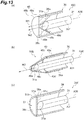
- the configuration which closes the tip end opening 36c may be a configuration shown in the following first, second and third modified examples.
- a catheter kit 30C has a protection cap 48.
- the protection cap 48 may be detachable from the hoop 36. Also, the protection cap 48 may be fixed to the hoop 36 by an adhesive or the like so that it cannot be removed from the hoop 36.
- the protection cap 48 is formed of a material transparent to the laser light L.
- the protection cap 48 has a cap main body 48a and a flange part 48b.
- the cap main body 48a has a cylindrical shape.
- the cap main body 48a is fitted into the hoop tip end portion 36a.
- the flange part 48b is provided on the tip end side of the cap main body 48a.
- the flange part 48b has a disk shape.
- the flange part 48b has a diameter substantially the same as a diameter of the outer circumferential surface of the hoop 36. That is, the diameter of the flange part 48b is larger than an inner diameter of the tip end opening 36c. According to such a configuration, a base end surface of the flange part 48b is in contact with the tip end surface of the hoop tip end portion 36a. As a result, an insertion depth of the protection cap 48 can be defined.
- the protection cap 48 has a catheter arrangement part 48c which defines a position of the catheter tip end portion 31a.
- the catheter arrangement part 48c aligns a central axis A31 of the catheter 31 with a central axis A36 of the hoop 36.
- the catheter arrangement part 48c defines the position of the catheter tip end portion 31a in a radial direction of the hoop 36.
- the catheter arrangement part 48c also defines a direction of the catheter 31 (that is, an emitting direction of the laser light L) in a predetermined direction. According to such a catheter arrangement part 48c, the position and posture of the catheter tip end portion 31a with respect to the light receiving part 6 can be defined with high accuracy. Therefore, it is possible to obtain an accurate light intensity value. In addition, it is possible to curb the occurrence of variations in light intensity for each measurement.
- the catheter arrangement part 48c is a tapered hole and extends from a base end surface of the cap main body 48a toward the flange part 48b. A diameter of the catheter arrangement part 48c gradually decreases toward the flange part 48b.
- the catheter arrangement part 48c has a base end opening 48d provided in a base end surface thereof, and a bottom portion 48e provided on the flange part 48b side. An inner diameter of the base end opening 48d is larger than an outer diameter of the catheter 31. Furthermore, the inner diameter of the base end opening 48d is slightly smaller than the inner diameter of the hoop 36. A diameter of the bottom portion 48e is smaller than the outer diameter of the catheter 31. Therefore, the tip end surface of the catheter tip end portion 31a is not in contact with the bottom portion 48e.
- the catheter tip end portion 31a when the catheter 31 is inserted into the hoop 36 from the base end side toward the tip end side, the catheter tip end portion 31a can be suitably guided to the catheter arrangement part 48c.
- the protection cap 48 when the protection cap 48 is used, the tip end surface of the catheter tip end portion 31a does not protrude from the tip end surface of the hoop tip end portion 36a. Therefore, the position of the catheter tip end portion 31a in the emitting direction of the laser light L is defined.
- a shape of the catheter arrangement part 48c may be configured so that an optical axis of the laser light L intersects a tapered surface of the catheter arrangement part 48c (refer to an arrow W1).
- the shape of the catheter arrangement part 48c may be configured so that the optical axis of the laser light L does not intersect the tapered surface. That is, the shape of the catheter arrangement part 48c may be configured so that the optical axis of the laser light L intersects the bottom portion 48e (refer to an arrow W2).
- a catheter kit 30D according to a second modified example can also regulate the position of the catheter tip end portion 31a, like the catheter kit 30C of the first modified example.
- the catheter kit 30D has a protection cap 49.
- the protection cap 49 may be detachable from the hoop 36.
- the protection cap 49 may be fixed to the hoop 36 by an adhesive or the like so that it cannot be removed from the hoop 36.
- the protection cap 49 has a main body tubular part 49a and a tapered tubular part 49b.
- the main body tubular part 49a is a tubular member which covers the hoop tip end portion 36a.
- An inner diameter of the main body tubular part 49a is substantially the same as or slightly smaller than the outer diameter of the hoop 36.
- the tapered tubular part 49b is provided on the tip end side of the main body tubular part 49a.
- the tapered tubular part 49b has a truncated cone shape.
- An outer diameter of the tapered tubular part 49b gradually decreases from a portion thereof which is continuous with the main body tubular part 49a to the tip end side.
- the tapered tubular part 49b has a tapered hole.
- An inner diameter of the tapered hole gradually decreases towards the tip end.
- the tapered hole is a catheter arrangement part 49c.
- the catheter arrangement part 49c is a tapered hole.
- the tapered hole extends from a boundary between the main body tubular part 49a and the tapered tubular part 49b toward the tip end.
- the diameter of the catheter arrangement part 49c gradually decreases toward the tip end.
- the catheter arrangement part 49c has a base end opening 49d and a tip end bottom portion 49e.
- An inner diameter of the base end opening 49d is substantially the same as the outer diameter of the hoop 36.
- a diameter of the tip end bottom portion 49e is smaller than the outer diameter of the catheter 31. Therefore, the tip end surface of the catheter tip end portion 31a is not in contact with the tip end bottom portion 49e.
- the catheter tip end portion 31a when the catheter 31 is inserted into the hoop 36 from the base end side to the tip end side, the catheter tip end portion 31a can be suitably guided to the catheter arrangement part 49c. Also, when the protection cap 49 is used, the tip end surface of the catheter tip end portion 31a protrudes from the tip end surface of the hoop tip end portion 36a. According to such a configuration, the catheter tip end portion 31a can be brought close to the light receiving part 6 in a state in which the catheter tip end portion 31a is protected.
- the laser light L passes through the tapered tubular part 49b and is incident on the light receiving part 6.
- the optical axis of the laser light L intersects the tip end bottom portion 49e without intersecting the tapered surface (refer to an arrow W3).
- the shape of the catheter arrangement part 49c may be so that the optical axis of the laser light L intersects the tapered surface.
- a catheter kit 30E has a protection cover part 51.
- the protection cover part 51 has a disk shape.
- the protection cover part 51 has an outer circumferential surface 51a, a tip end surface 51b, and a base end surface 51c.
- An outer diameter of the protection cover part 51 is approximately equal to the inner diameter of the hoop 36.
- the protection cover part 51 is fitted into the tip end opening 36c of the hoop tip end portion 36a.
- the tip end surface 51b of the protection cover part 51 is exposed to the outside.
- the base end surface 51c of the protection cover part 51 faces the inside of the hoop 36. That is, the catheter tip end portion 31a faces the base end surface 51c.
- the laser light L emitted from the catheter tip end portion 31a passes through the protection cover part 51 and is then incident on the light receiving part 6. Therefore, the protection cover part 51 is formed of a material transparent to the laser light L.
- the protection cover part 51 is fixed to the hoop 36 by an adhesive or the like so that it cannot be removable therefrom. That is, the protection cover part 51 is integrated with the hoop 36. Specifically, the outer circumferential surface 51a of the protection cover part 51 is fixed to the inner circumferential surface of the hoop 36 by adhesion or the like. According to such a configuration, the protection cover part 51 is not separated from the hoop 36. Therefore, the catheter tip end portion 31a can be reliably protected.
- the catheter kit 30 has included the position adjustment mechanism 47 which switches the position of the catheter 31 with respect to the hoop 36.
- the specific configuration of the position adjustment mechanism may be as shown in the following fourth and fifth modified examples.
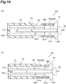
- a catheter kit 30J has a position adjustment mechanism 59 which has a different structure from that in the third embodiment.
- the position adjustment mechanism 59 is a tube 59a formed of silicone rubber or the like.
- the tube 59a is disposed between the hoop 36 and the holding plug 61.
- the tube 59a maintains and changes a gap between the hoop base end portion 36b and a holding plug tip end surface 61a.
- the hoop base end portion 36b is inserted into a tube tip end portion 59b.
- a press-fit part 61b of the holding plug 61 is inserted into a tube base end portion 59c.
- the position adjustment mechanism 59 is a double structure configured with the tube 59a and the hoop 36.
- the tube base end portion 59c is fixed to the holding plug 61.
- the tube tip end portion 59b is slidable with respect to the hoop base end portion 36b.
- Such a configuration can be realized by setting an inner diameter of the tube tip end portion 59b and an outer diameter of the hoop base end portion 36b to predetermined dimensional values.
- the tube 59a maintains a gap between the hoop base end portion 36b and the holding plug tip end surface 61a at a predetermined distance.
- the catheter tip end portion 31a is disposed on the base end side by a gap with respect to the hoop tip end portion 36a (the first position). That is, the catheter tip end portion 31a is protected by the hoop 36.
- the holding plug 61 is pushed to the tip end side. Then, slippage occurs between the tube tip end portion 59b and the hoop base end portion 36b. As a result, the tube 59a and the holding plug 61 move integrally to the tip end side. That is, the gap between the hoop base end portion 36b and the holding plug tip end surface 61a is reduced. Then, finally, the holding plug tip end surface 61a comes into contact with the hoop base end portion 36b. At this time, the catheter tip end portion 31a coincides with the position of the hoop tip end portion 36a. That is, the catheter tip end portion 31a is disposed at a position (the second position) suitable for measurement of the light intensity.
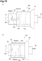
- a catheter kit 30K according to a fifth modified example may have a position adjustment mechanism 62 having yet another configuration.
- the position adjustment mechanism 62 is configured with a guide pin 62a and a guide groove 62b.
- the guide pin 62a and the guide groove 62b reliably switch between a state in which the catheter tip end portion 31a is protected and a state in which the measurement of the laser light L is performed using the catheter kit 30K.
- the position adjustment mechanism 62 can reliably maintain each of the states.
- the catheter kit 30K has a tube 63.
- the tube 63 is disposed between the hoop 64 and the holding plug 65. That is, like the position adjustment mechanism 62 according to the fourth modified example, the position adjustment mechanism 62 according to the fifth modified example has a so-called double structure.
- the guide groove 62b is provided in the outer circumferential surface of the hoop base end portion 64a.
- the guide groove 62b may penetrate the side wall of the hoop 64.
- the guide groove 62b may have a bottom portion.
- the guide groove 62b includes a first restricting part 62c and a second restricting part 62d which extend in a circumferential direction, and a connecting groove part 62e which extends in an axial direction.
- One end of the first restricting part 62c and one end of the second restricting part 62d are connected by the connecting groove part 62e.
- the connecting groove part 62e extends in the axial direction of the hoop 64.
- the first restricting part 62c is provided on the hoop base end surface side.
- the second restricting part 62d is provided on the tip end side from the first restricting part 62c. A distance from the first restricting part 62c to the second restricting part 62d corresponds to a movement distance of the catheter 31.
- the guide pin 62a is provided on an inner circumferential surface of the tube 63.
- the guide pin 62a is a cylindrical protrusion.
- the guide pin 62a extends from the inner circumferential surface of the tube 63 in the radial direction thereof.
- a diameter of the guide pin 62a is substantially the same as or slightly smaller than that of the guide groove 62b.
- the guide pin 62a is fitted into the first restricting part 62c.
- the catheter tip end portion 31a is in a protected state in which it is disposed on the inner side of the hoop 64 (at the first position).
- the first restricting part 62c extends in the circumferential direction.
- the guide pin 62a does not move in the axial direction. Therefore, since the catheter tip end portion 31a is disposed at the inside of the hoop 64, the protected state can be reliably maintained.
- the tube 63 is rotated in a direction in which the first restricting part 62c extends. Then, the guide pin 62a moves to the base end of the connecting groove part 62e. Then, the guide pin 62a is moved along the connecting groove part 62e. That is, the tube 63 and the holding plug 65 are moved to the tip end side. Due to this movement, the catheter tip end portion 31a coincides with the hoop tip end portion 36a. Then, after the guide pin 62a is moved to the tip end of the connecting groove part 62e, the tube 63 is rotated in the circumferential direction.
- the guide pin 62a is fitted into the second restricting part 62d.
- the catheter tip end portion 31a is in a measurement state in which it coincides with the hoop tip end portion 36a (the second position).
- the second restricting part 62d extends in the circumferential direction, like the first restricting part 62c.
- the guide pin 62a does not move in the axial direction. Therefore, a state in which the catheter tip end portion 31a is disposed at the hoop tip end portion 36a can be reliably maintained.
- the catheter kit 30 has the mechanism for holding the position of the catheter 31 with respect to the hoop 36.
- the specific configuration of the mechanism may be as shown in the following sixth, seventh and eighth modified examples.
- a catheter kit 30L may have a clip 66 as the mechanism for holding the position of the catheter 31.
- the clip 66 is mounted on the hoop base end portion 36b.
- the clip 66 generates a force as if it crushes the hoop 36 in the radial direction.
- the inner circumferential surface of the hoop 36 is in tight contact with the outer circumferential surface of the catheter 31.
- the clip 66 is mounted to sandwich the hoop 36 in the radial direction. Therefore, side walls of the hoop 36 crushed by the clip 66 sandwich the catheter 31.
- the position of the catheter 31 with respect to the hoop 36 is maintained. Also, when the hoop 36 is moved, the clip 66 is removed. According to the holding mechanism by the clip 66, it is possible to easily switch between a state in which the catheter 31 is held and a state in which the catheter can be moved.
- a catheter kit 30P according to a seventh modified example may have a tube 67 as the holding mechanism.
- the configuration is similar to the configuration of the fourth modified example. That is, it has a double structure. The difference from the configuration of the fourth modified example is that it is difficult for the tube tip end portion 67a to slide with respect to the hoop base end portion 36b.
- the inner diameter of the tube 63 is smaller than the outer diameter of the hoop 36. As a result, when the hoop 36 is inserted into the tube 63, a press-fit state is obtained.
- a catheter kit 30Q may have a clamp 68 as the holding mechanism.
- the clamp 68 is a U-shaped component capable of detachably mounting the catheter base end portion 31b.
- the clamp 68 includes a fixing part 69 which is fixed to the outer circumferential surface of the hoop 36.
- the catheter base end portion 31b is inserted from an opening of the clamp 68 in the radial direction. As a result, the catheter base end portion 31b is fixed to the clamp 68.
- the clamp 68 is then fixed to the hoop 36 by the fixing part 69.
- the catheter 31 is held with respect to the hoop 36.
- the catheter kit 30 has the protection cap 48 which is mounted on the hoop tip end portion 36a at the time of storage.
- the configuration for protecting the catheter tip end portion 31a disposed to coincide with the hoop tip end portion 36a may be configured as shown in the following modified example 9.
- a catheter kit 30S according to a ninth modified example has a protection cap 72.
- the protection cap 72 has a configuration similar to that of the protection cap 72 of the second modified example.
- the difference from the protection cap 49 of the second modified example is that the protection cap 72 according to the twelfth modified example can be moved with respect to the hoop 36.
- the protection cap 72 is shallowly covered on the hoop tip end portion 36a. According to such a configuration, a space is provided between the cap tip end portion 72a of the protection cap 72 and the catheter tip end portion 31a. Therefore, the catheter tip end portion 31a can be appropriately protected.
- the protection cap 72 when the measurement of the laser light L using the catheter kit 30S is performed, the protection cap 72 is pushed to the hoop 36 side. A distance between a cap tip end portion 72a and the catheter tip end portion 31a is reduced by the pushing. Then, when the protection cap 72 and the hoop 36 are regarded as one hoop member, the protection cap 72 changes a relative position between the catheter tip end portion 31a and the hoop member. Accordingly, the protection cap 72 may be defined as a broad position adjustment mechanism. Furthermore, the catheter tip end portion 31a is guided along a tapered inner circumferential surface of the protection cap 72.
- the central axis A31 of the catheter 31 follows the central axis A36 of the hoop 36. Therefore, the variations in the position and posture of the catheter tip end portion 31a from which the laser light L is emitted are curbed. As a result, accurate measurement of light intensity can be performed.
- the catheter kit may be freely combined with the first, second, third and ninth modified examples of the tip end shape, the fourth and fifth modified examples of the position adjustment mechanism, and the sixth, seventh and eighth modified examples of the holding mechanism according to conditions required for the catheter kit.
Landscapes
- Health & Medical Sciences (AREA)
- Surgery (AREA)
- Physics & Mathematics (AREA)
- Life Sciences & Earth Sciences (AREA)
- Engineering & Computer Science (AREA)
- Medical Informatics (AREA)
- Nuclear Medicine, Radiotherapy & Molecular Imaging (AREA)
- Electromagnetism (AREA)
- Optics & Photonics (AREA)
- Biomedical Technology (AREA)
- Heart & Thoracic Surgery (AREA)
- Otolaryngology (AREA)
- Molecular Biology (AREA)
- Animal Behavior & Ethology (AREA)
- General Health & Medical Sciences (AREA)
- Public Health (AREA)
- Veterinary Medicine (AREA)
- Media Introduction/Drainage Providing Device (AREA)
- Laser Surgery Devices (AREA)
Abstract
Description
- The present invention relates to a catheter kit which accommodates a catheter with a built-in optical fiber.
- A catheter with a built-in optical fiber is used for patient diagnosis and treatment. For example,
Patent Document 1 discloses this in thrombolytic therapy. When a catheter is used for thrombolytic therapy, the catheter is first inserted into a patient's body. Thereafter, an affected area is irradiated with laser light through the catheter. -
- [Patent Literature 1] Japanese Patent No.
4409499 - [Patent Literature 2] Japanese Examined Utility Model Publication No.
H6-42182 - [Patent Literature 3] Japanese Unexamined Patent Publication No.
H8-262278 - The catheter is inserted into a body at the time of use. Therefore, when the catheter is inserted into the body, it is required to be sufficiently sterilized. Therefore, during storage and transportation, the catheter is accommodated in a tubular container called a hoop to maintain cleanliness. Thus, in order to maintain the cleanliness of the catheter, it is desirable to store the catheter in the hoop until immediately before use.
- In a method disclosed in
Patent Document 1, it is desirable to irradiate an affected area with laser light having a predetermined intensity. Therefore, as disclosed inPatent Documents - Therefore, an object of the present invention is to provide a catheter kit allowing a light intensity confirmation operation to be performed easily while maintaining cleanliness of a catheter.
- A catheter kit according to one aspect of the present invention includes a catheter having an optical fiber, and a catheter accommodating tool which accommodates the catheter, wherein the catheter accommodating tool includes a tubular hoop, and a closing part provided at an end portion of the hoop, and the closing part has a transmission window which transmits light emitted from the catheter.
- In the catheter kit, the end portion of the hoop which accommodates the catheter is closed by the closing part. Thus, a tip end of the catheter can be protected. Furthermore, the transmission window is provided at the closing part. Therefore, the light provided from the optical fiber can be obtained in a state in which the catheter is accommodated in the hoop without taking out the catheter from the hoop. Thus, cleanliness of the catheter can be maintained, and a light intensity confirmation operation can be easily performed.
- The end portion of the hoop may have an opening, a catheter tip end portion from which light transmitted through the optical fiber is emitted may be provided at the end portion of the hoop, and the transmission window may close the opening and may transmit the light. According to such a configuration, it is possible to measure the light intensity in the state in which the catheter is accommodated in the hoop. Therefore, the cleanliness of the catheter can be maintained, and the light intensity confirmation operation can be easily performed.
- The closing part may be a cap member which is detachably mounted on the hoop. According to such a configuration, the configuration of the hoop end portion can be selected according to the form of measurement of the light intensity. That is, it is possible to select a mode in which the measurement is performed while the end from which light is emitted is protected, and a mode in which the measurement is performed while light is directly incident on a measurement device.
- The closing part may be a cover part which is a part of the hoop and is integrated with the hoop. According to such a configuration, the cover part is not separated from the hoop. Therefore, the tip end portion of the catheter can be protected reliably.
- The hoop may have a through hole which extends in a direction intersecting a longitudinal direction of the hoop and extends from an outer circumferential surface to an inner circumferential surface. According to such a configuration, a sterilization gas can be appropriately provided to the catheter accommodated in the hoop.
- The catheter accommodating tool may further include a position adjustment part provided at the hoop, the hoop may include a hoop tip end portion which is the end portion, and a hoop base end portion which is opposite to the tip end portion, and the position adjustment part may change a position of the catheter tip end portion from which the light transmitted through the optical fiber with respect to the hoop tip end portion is emitted. According to such a configuration, it is possible to change the position of the catheter tip end portion at the time of storage and measurement. That is, at the time of storage, it is possible to dispose the catheter tip end portion inside from the hoop tip end portion. As a result, the catheter tip end portion can be protected. Furthermore, at the time of measurement, it is possible to align the catheter tip end portion with the hoop tip end portion. As a result, it is possible to curb occurrence of variation in a distance from the catheter tip end portion to a light receiving part.
- According to the present invention, a catheter kit capable of maintaining cleanliness of a catheter and allowing a light intensity confirmation operation to be performed easily is provided.
-
-
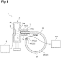
FIG. 1 is a view showing a configuration of a light measurement device according to a first embodiment. -
FIG. 2 is an enlarged cross-sectional view showing a configuration of an adapter and a catheter kit shown inFIG. 1 . -
FIG. 3 is a cross-sectional view for explaining an operation of a position adjustment mechanism. -
FIG. 4 is a flowchart showing a main process of a light measurement method according to the first embodiment. -
FIG. 5 is a view for explaining the main process shown inFIG. 4 . -
FIG. 6 is a view for explaining a main process following the process shown inFIG. 5 . -
FIG. 7 is a view for explaining a main process following the process shown inFIG. 6 . -
FIG. 8 is a view showing a configuration of a light measurement device according to a second embodiment. -
FIG. 9 is a flowchart showing a main process of a light measurement method according to the second embodiment. -
FIG. 10 is a view for explaining the main process shown inFIG. 9 . -
FIG. 11 is a view for explaining a main process following the process shown inFIG. 10 . -
FIG. 12 is a view for explaining a main process following the process shown inFIG. 11 . -
FIG. 13 is a perspective view showing a cross section of a catheter kit according to first, second and third modified examples. -
FIG. 14 is a side view showing a cross section of a catheter kit according to a fourth modified example. -
FIG. 15 is a plan view showing a catheter kit according to a fifth modified example. -
FIG. 16 is a side view showing a cross section of a catheter kit according to sixth, seventh and eighth modified examples. -
FIG. 17 is a perspective view showing a cross section of a catheter kit according to a ninth modified example. - Hereinafter, embodiments of the present invention will be described in detail with reference to the attached drawings. In the description of the drawings, the same elements will be designated by the same reference symbols, and duplicate descriptions will be omitted..
- As shown in
FIG. 1 , alight measurement device 1 measures an intensity of laser light L. The laser light L is provided from alight source 101 to acatheter kit 30. Then, the laser light L is emitted from thecatheter kit 30. Thelight measurement device 1 includes apower meter 2 and an adapter 3 (a second adapter). In the following description, the side of the respective elements from which light is emitted is referred to as a "tip end." The side opposite to the "tip end" is referred to as a "base end." For example, in thecatheter kit 30, an end portion which emits the laser light L is a "tip end portion." An end portion which receives the laser light L is a "base end portion." - The
power meter 2 includes acase body 4, alight receiving part 6, a mountingpart 7, and aprocessing device 8. - The
case body 4 holds a relative positional relationship between the light receivingpart 6 and the mountingpart 7. Thecase body 4 is formed of an opaque material. Thecase body 4 and theadapter 3 constitute a closed space. Thelight receiving part 6 is disposed inside the closed space. According to such a configuration, it is possible to prevent stray light from being incident on thelight receiving part 6. - The
light receiving part 6 receives the laser light L output from thecatheter kit 30. Thelight receiving part 6 includes, for example, a light absorber. Thelight receiving part 6 converts absorbed light into heat. Thereafter, thelight receiving part 6 outputs a change of heat as a change in an electrical signal. For example, the light absorber may include 3A-P manufactured by Ophir, and the like. The electrical signal output from thelight receiving part 6 is transmitted to theprocessing device 8 via a signal cable. Theprocessing device 8 obtains the intensity of the light received by thelight receiving part 6 on the basis of the electrical signal. Then, theprocessing device 8 displays an intensity value thereof. - The mounting
part 7 is provided at a position facing thelight receiving part 6. The mountingpart 7 may be part of thecase body 4. The mountingpart 7 defines a position of thecatheter kit 30 with respect to thelight receiving part 6. The position of thecatheter kit 30 with respect to thelight receiving part 6 includes a distance from a tip end portion of thecatheter kit 30 to thelight receiving part 6 in a traveling direction of the laser light L emitted from thecatheter kit 30. Furthermore, the position includes a position of the tip end portion of thecatheter kit 30 with respect to thelight receiving part 6 in a plane orthogonal to the traveling direction of the laser light L.The mounting part 7 has a standingtubular part 7a which protrudes from thecase body 4. Furthermore, the standingtubular part 7a has anadapter arrangement part 7H which is a through hole. Thecatheter kit 30 is disposed in theadapter arrangement part 7H via theadapter 3. A tip end of theadapter arrangement part 7H is a tip end opening 7Ha provided in an inner wall of thecase body 4. A base end of theadapter arrangement part 7H is a base end opening 7Hb provided in an end portion of the mountingpart 7. - As shown in
FIG. 2 , theadapter 3 allows thecatheter kit 30 to be mounted in thepower meter 2. Theadapter 3 may be formed of, for example, polyacetal. Theadapter 3 has an adaptermain body 9 and anadapter flange 11. The adaptermain body 9 and theadapter flange 11 are integrally formed. The adaptermain body 9 is disposed in theadapter arrangement part 7H. The adaptermain body 9 has an adaptertip end surface 3a. A male thread may be provided on an outer circumferential surface of the adaptermain body 9. Theadapter flange 11 is provided on the base end side. Theadapter flange 11 has an adapterbase end surface 3b. An outer diameter of theadapter flange 11 is larger than an inner diameter of theadapter arrangement part 7H. Theadapter flange 11 may be in contact with a mountingend surface 7b of the mountingpart 7. - The
adapter 3 has ahoop arrangement part 3H which holds a tip end of thecatheter kit 30. Thehoop arrangement part 3H is a hole which extends from the adapterbase end surface 3b toward the adaptertip end surface 3a. Also, the base end side of thehoop arrangement part 3H is a base end opening 3Hb provided in the adapterbase end surface 3b. The base end opening 3Hb may be chamfered (tapered). An adaptertip end wall 3d is provided on the tip end side of thehoop arrangement part 3H. When thecatheter kit 30 is disposed in thehoop arrangement part 3H, the tip end of thecatheter kit 30 is in contact with the adaptertip end wall 3d. More specifically, a tip end surface of aprotection cap 43 which will be described later is in contact with the adaptertip end wall 3d. Thus, the adaptertip end wall 3d defines an insertion depth of thecatheter kit 30 with respect to theadapter 3. Alight passing part 3e which is a through hole is provided in the adaptertip end wall 3d. Thelight passing part 3e guides the laser light L emitted from thecatheter kit 30 to thelight receiving part 6. Therefore, acontact part 3c (a second contact part) is constituted by the adaptertip end wall 3d and thelight passing part 3e. - Next, the
catheter kit 30 will be described in detail. Thecatheter kit 30 includes acatheter 31 and a catheteraccommodating tool 32. Thecatheter 31 has a built-inoptical fiber 33. Thecatheter 31 may also includeother components 34 required for treatment and examination, in addition to theoptical fiber 33. Theoptical fiber 33 has an optical fibertip end portion 33a and an optical fiberbase end portion 33b. The optical fibertip end portion 33a is inserted into a human body. Furthermore, the optical fibertip end portion 33a emits the laser light L. The light source 101 (refer toFIG. 1 ) is connected to the optical fiberbase end portion 33b. Additionally, the laser light L is provided to the optical fiberbase end portion 33b. - The catheter
accommodating tool 32 accommodates thecatheter 31. The catheteraccommodating tool 32 includes ahoop 36, a holding plug 37 (a catheter holding part), the protection cap 43 (a closing part, a cap member), and a bellows 46 (refer toFIG. 1 ). - The
hoop 36 has a tubular pipe shape. Thehoop 36 described in the embodiment is used at a medical site. Thehoop 36 refers to a resin tube into which thecatheter 31 is inserted. Thehoop 36 does not have to be flexible. Thehoop 36 may be flexible or non-flexible. Thehoop 36 includes a hooptip end portion 36a in which a cathetertip end portion 31a is disposed, and a hoopbase end portion 36b in which the catheterbase end portion 31b side is disposed. Atip end opening 36c is provided in the hooptip end portion 36a. That is, the hooptip end portion 36a is not closed. In other words, the hooptip end portion 36a is open. The hoopbase end portion 36b also has a base end opening 36d. That is, the hoopbase end portion 36b is also not closed. In other words, the hoopbase end portion 36b is open. Agas introduction hole 36e is provided in thehoop 36. Thegas introduction hole 36e is provided in a side wall of thehoop 36. Additionally, thegas introduction hole 36e passes therethrough from an outer circumferential surface to an inner circumferential surface. - Here, a relationship between an inner diameter (f) and an outer diameter (d) of the
hoop 36 and an inner diameter (e) of thelight passing part 3e of theadapter 3 is f<e<d. According to this dimensional relationship, it is possible to prevent the cathetertip end portion 31a from coming into contact with an unsterilized portion. - The holding
plug 37 is disposed to be press-fitted into the base end opening 36d on the side of the hoopbase end portion 36b. The holdingplug 37 includes acatheter arrangement part 38, a press-fit part 39 which is press-fitted into thehoop 36, and aflange part 41. Thecatheter arrangement part 38 is a through hole which holds thecatheter 31. The holdingplug 37 holds the position of thecatheter 31 with respect to thehoop 36 when inserted into thehoop 36. That is, the holdingplug 37 is fixed to thehoop 36. Additionally, the holdingplug 37 holds thecatheter 31. Thus, the holdingplug 37 inserted into thehoop 36 holds the position of thecatheter 31 with respect to thehoop 36. - The
catheter arrangement part 38 is disposed on the side of the catheterbase end portion 31b. An inner diameter of thecatheter arrangement part 38 is slightly smaller than an outer diameter of thecatheter 31. According to such a configuration, an inner circumferential surface of thecatheter arrangement part 38 is press-fitted onto an outer circumferential surface of thecatheter 31. As a result, the position of thecatheter 31 with respect to the holdingplug 37 is held. The press-fit part 39 is press-fitted into thehoop 36 from the base end opening 36d of the hoopbase end portion 36b. An outer diameter of the press-fit part 39 is slightly larger than an inner diameter of thehoop 36. According to such a configuration, an outer circumferential surface of the press-fit part 39 is press-fitted into an inner circumferential surface of thehoop 36. As a result, a position of the holdingplug 37 with respect to thehoop 36 is held. Theflange part 41 is provided on the base end side of the press-fit part 39. An outer diameter of theflange part 41 is larger than an inner diameter of thehoop 36. - The
protection cap 43 is mounted on thehoop 36. Theprotection cap 43 has a tubular shape of which one end is closed and the other end is open. Theprotection cap 43 may be formed of, for example, acrylic. Theprotection cap 43 closes the tip end opening 36c of the hooptip end portion 36a. According to such a configuration, the cathetertip end portion 31a is protected. Further, theprotection cap 43 transmits the laser light L emitted from the cathetertip end portion 31a. Theprotection cap 43 has a captip end portion 43a and a capbase end portion 43b. The captip end portion 43a has atransmission window 43c. Thetransmission window 43c closes thetip end opening 36c. Furthermore, thetransmission window 43c transmits the laser light L. The capbase end portion 43b has a base end opening 43Hb of thehoop arrangement part 43H into which thehoop 36 can be inserted. - The bellows 46 is disposed between the
hoop 36 and the holdingplug 37. The bellows 46 which is a so-called bellows tube can extend and contract in an axial direction thereof. The bellows 46 has an elasticity to maintain a predetermined length when no external force is applied. For example, when the bellows 46 is pressed in the axial direction, a length of thebellows 46 is reduced. On the other hand, when the pressing is stopped, the length of thebellows 46 returns to the length before the pressing. - The bellows 46 has a bellows
tip end portion 46a and a bellowsbase end portion 46b. The bellows tipend portion 46a is in contact with the hoopbase end portion 36b. The bellows baseend portion 46b is in contact with theflange part 41 of the holdingplug 37. According to such a configuration, a constant gap is maintained between a base end surface of the hoopbase end portion 36b and an end surface of theflange part 41 of the holding plug 37 (refer to a gap D1 inFIG. 3(a) ). On the other hand, it is assumed that the holdingplug 37 is pushed to thehoop 36 side and the press-fit part 39 of the holdingplug 37 is pressed into thehoop 36. Also in this case, a restoring force of thebellows 46 is generated. However, the restoring force is smaller than a frictional force between the press-fit part 39 and the inner circumferential surface of thehoop 36. Accordingly, a state in which the holdingplug 37 is pushed to thehoop 36 side is maintained (refer to a gap D2 inFIG. 3(b) ). The bellows 46 may not generate the restoring force. In this case, thebellows 46 can maintain a stretched state (that is, a state ofFIG. 3(a) ) and a contracted state (a state ofFIG. 3(b) ) without requiring additional components. - That is, with the
bellows 46 and the holdingplug 37, the position of thecatheter 31 with respect to thehoop 36 can be switched to a first position or a second position. Therefore, thebellows 46 and the holdingplug 37 constitute a position adjustment mechanism 47 (a position adjusting part). First, when the holdingplug 37 is in a state in which it is not pushed into thehoop 36, thecatheter 31 is held at the first position. In the first position, the cathetertip end portion 31a is disposed closer to the base end from the hooptip end portion 36a (refer toFIG. 3(a) ). Here, a gap from a tip end surface of the hooptip end portion 36a to a tip end surface of the cathetertip end portion 31a is D3. The gap D3 is obtained by subtracting the gap D2 from the gap D1 (D3 = D1-D2). On the other hand, when the holdingplug 37 is in a state in which it is pushed into thehoop 36, thecatheter 31 is held at the second position. In this second position, the positions of the hooptip end portion 36a and the cathetertip end portion 31a coincide with each other (refer toFIG. 3(b) ). - Next, a light intensity measurement method using the
light measurement device 1 will be described with reference to a flowchart shown inFIG. 4 . First, a process of preparing thecatheter kit 30 will be described. - Step S2 is carried out (refer to
FIG. 5(a) ). First, theprotection cap 43 is mounted on thehoop 36. In Step S2, theprotection cap 43 is completely covered on thehoop 36. In other words, the tip end surface of the hooptip end portion 36a is brought into contact with an inner surface of the captip end portion 43a. Also, in Step S2, a gap may be provided between the tip end surface of the hooptip end portion 36a and the inner surface of the captip end portion 43a. - Next, Step S4 is performed (refer to
FIG. 5(b) ). In Step S4, thecatheter 31 is accommodated in thehoop 36. Further, in Step S4, the cathetertip end portion 31a does not coincide with the hooptip end portion 36a. That is, thebellows 46 is disposed between thehoop 36 and the holdingplug 37. That is, thecatheter 31 is accommodated in thehoop 36 so that thecatheter 31 is at the first position. Specifically, the holdingplug 37 is mounted on the bellowsbase end portion 46b. Further, the bellows tipend portion 46a is mounted on the base end surface of the hoopbase end portion 36b. Here, thebellows 46 has a predetermined length in the axial direction. The predetermined length corresponds to, for example, a distance from the tip end surface of the hooptip end portion 36a to the tip end surface of the cathetertip end portion 31a in an accommodated state. In a procedure of performing Steps S2 and S4, Step S4 may be performed after Step S2, as described above. In addition, Step S2 may be performed after Step S4. - Next, Step S6 is performed (refer to
FIG. 5(c) ). In Step S6, thecatheter kit 30 is sterilized. Specifically, first, thecatheter kit 30 is put into asterilization bag 102. Next, thesterilization bag 102 is sealed. Next, thecatheter kit 30 and thesterilization bag 102 are placed inside a chamber (not shown). Next, the inside of the chamber is degassed. Next, a sterilization gas G is supplied into the chamber. Thesterilization bag 102 formed so that one side surface is formed of vinyl and the other side surface is formed of a non-woven fabric. Therefore, the sterilization gas G is filled into the bag even when thesterilization bag 102 is sealed. An example of the sterilization gas G includes ethylene oxide gas (EoG). Then, thecatheter kit 30 is sterilized by the sterilization gas G. - However, the
catheter 31 is accommodated in thehoop 36. The hooptip end portion 36a is closed by aprotection cap 43. The hoopbase end portion 36b is closed by the holdingplug 37 and thebellows 46. Here, thehoop 36 has agas introduction hole 36e. The sterilization gas G is introduced into thehoop 36 from thegas introduction hole 36e. Therefore, according to thegas introduction hole 36e, thecatheter 31 accommodated in thehoop 36 can be reliably sterilized. After the sterilization gas G is filled in, the sterilization gas G is degassed from the chamber. - The
catheter kit 30 which has been sterilized by Steps S2, S4 and S6 as described above is prepared. - Subsequently, a process of measuring the
catheter kit 30 will be described. - First, Step S8 is performed (refer to
FIG. 6(a) ). Specifically, thecatheter kit 30 is taken out of thesterilization bag 102. Then, thelight source 101 is connected to the optical fiberbase end portion 33b of theoptical fiber 33. - Next, Step S10 is performed (refer to
FIG. 6(b) ). In Step S10, the holdingplug 37 is pushed into thehoop 36. That is, the position of the cathetertip end portion 31a coincides with the position of the hooptip end portion 36a. - Next, Step S12 is performed (refer to
FIG. 7(a) ). First, thecatheter kit 30 is mounted in thepower meter 2. More specifically, theadapter 3 is screwed into the mountingpart 7 of thepower meter 2. Then, the tip end side (theprotection cap 43 side) of thecatheter kit 30 is inserted into theadapter 3. - Next, Step S14 is performed (refer to
FIG. 7(a) ). Specifically, thelight source 101 is operated. As a result, the laser light L is generated. The laser light L is emitted from the cathetertip end portion 31a through theoptical fiber 33. The emitted laser light L is incident on thelight receiving part 6. Thelight receiving part 6 outputs an electrical signal according to the incident laser light L. The content of the signal is displayed on theprocessing device 8. It is confirmed that the predetermined intensity of the laser light L is obtained on the basis of the displayed content of the signal. - Next, Step S16 is performed (refer to
FIG. 7(b) ). Specifically, thecatheter kit 30 is pulled out of theadapter 3. Next, the holdingplug 37 is pulled out of thehoop 36. As a result, thecatheter 31 is taken out of thehoop 36. Then, in Step S18 (not shown), a predetermined treatment or examination is performed using thecatheter 31. - In the
light measurement device 1 according to the first embodiment, the mountingpart 7 defines the position of thehoop 36 with respect to thelight receiving part 6. As a result, it is not necessary to take out thecatheter 31 from thehoop 36 to measure the intensity of the laser light L. Then, it is possible to measure the intensity of the laser light L in a state in which thecatheter 31 is accommodated in thehoop 36. As a result, the cleanliness of thecatheter 31 can be maintained. Furthermore, thecatheter 31 does not have to be taken out of thehoop 36. As a result, the process required to measure the laser light L can be simplified. Therefore, according to thelight measurement device 1, the cleanliness of thecatheter 31 can be maintained, and the light intensity confirmation operation can be easily performed. - In the
catheter kit 30 according to the first embodiment, the position of thecatheter 31 with respect to thehoop 36 is held by the holdingplug 37. According to such a configuration, when the intensity of the laser light L is measured, it is possible to curb occurrence of variation of a distance from the cathetertip end portion 31a to thelight receiving part 6. - Furthermore, the
catheter kit 30 further includes theposition adjustment mechanism 47 which is provided at the hoopbase end portion 36b and changes the position of the cathetertip end portion 31a with respect to the hooptip end portion 36a in an extending direction of thehoop 36. According to such a configuration, it is possible to switch between the position of the cathetertip end portion 31a at the time of storage and the position of the cathetertip end portion 31a at the time of measurement. That is, at the time of storage, the cathetertip end portion 31a can be disposed on the inner side of the hooptip end portion 36a. As a result, the cathetertip end portion 31a can be protected. Furthermore, at the time of measurement, it is possible to align the cathetertip end portion 31a with the position of the hooptip end portion 36a. As a result, it is possible to curb the occurrence of the variation in the distance from the cathetertip end portion 31a to thelight receiving part 6. - The holding
plug 37 of thecatheter kit 30 holds the position of thecatheter 31 relative to the position of thehoop 36 so that the cathetertip end portion 31a is aligned with the hooptip end portion 36a in the extending direction of thehoop 36. According to such a configuration, the position of the hooptip end portion 36a is defined. As a result, the position of the cathetertip end portion 31a is defined. Therefore, the occurrence of the variation in the distance from the cathetertip end portion 31a to thelight receiving part 6 can be further curbed. - The
catheter kit 30 further includes theprotection cap 43 which is mounted on the hooptip end portion 36a and closes the tip end opening 36c of the hooptip end portion 36a. According to such a configuration, the cathetertip end portion 31a can be protected. - More specifically, the
catheter kit 30 further includes theprotection cap 43 which is mounted on thehoop 36, and theadapter 3 which disposes thehoop 36 on which theprotection cap 43 is mounted to the mountingpart 7. Thehoop 36 has the hooptip end portion 36a in which the cathetertip end portion 31a is disposed and which includes thetip end opening 36c. Theprotection cap 43 is mounted on the hooptip end portion 36a. Theprotection cap 43 has the captip end portion 43a including thetransmission window 43c which closes thetip end opening 36c and transmits the laser light L emitted from theoptical fiber 33. Theadapter 3 has thecontact part 3c with which the captip end portion 43a is in contact. According to such a configuration, theprotection cap 43 having thetransmission window 43c is disposed between the cathetertip end portion 31a and thelight receiving part 6. Thetransmission window 43c closes the tip end opening 36c of the hooptip end portion 36a. Therefore, the cathetertip end portion 31a can be protected. - In the light measurement method according to the first embodiment, the position of the
hoop 36 with respect to thelight receiving part 6 is defined in Step S12 in which thehoop 36 is disposed in the mountingpart 7. As a result, it is not necessary to take out thecatheter 31 from thehoop 36 to measure the intensity of the laser light L. Then, in Step S14 in which the intensity of the laser light L is obtained, it is possible to measure the intensity of the laser light L in a state in which thecatheter 31 is accommodated in thehoop 36. Therefore, the cleanliness of thecatheter 31 can be maintained. Furthermore, thecatheter 31 does not have to be taken out of thehoop 36. As a result, the process required to measure the laser light L can be simplified. Accordingly, according to the light measurement method, the cleanliness of thecatheter 31 can be maintained, and the light intensity confirmation operation can be easily performed. - A light measurement device and a catheter kit according to a second embodiment will be described. As shown in
FIG. 8 , thecatheter kit 30A of the second embodiment is different from thecatheter kit 30 of the first embodiment in that theposition adjustment mechanism 47 is not provided. On the other hand, thelight measurement device 1 of the second embodiment has the same configuration as that of thelight measurement device 1 of the first embodiment. Hereinafter, a light measurement method using thecatheter kit 30A which does not have theposition adjustment mechanism 47 will be described with reference to the flowchart ofFIG. 9 . - Step S2A is performed (
FIG. 10(a) ). First, theprotection cap 43 is mounted on thehoop 36. In Step S2A, theprotection cap 43 is not completely covered on thehoop 36. Specifically, the tip end surface of the hooptip end portion 36a is not in contact with the inner surface of the captip end wall 43d. That is, a predetermined gap D3 is provided between the inner surface of the captip end wall 43d and the tip end surface of the hooptip end portion 36a. - Step S4A is performed (refer to
FIG. 10(b) ). In Step S4A, thecatheter 31 is accommodated in thehoop 36. Here, in Step S2A, theprotection cap 43 is mounted on thehoop 36 so that the predetermined distance D3 is provided between theprotection cap 43 and thehoop 36. Additionally, in Step S4A, the cathetertip end portion 31a is disposed to coincide with the hooptip end portion 36a. Then, the predetermined gap D3 is also formed between the cathetertip end portion 31a and the captip end wall 43d. Therefore, the cathetertip end portion 31a can be protected because the cathetertip end portion 31a is not in contact with the inner surface of the captip end wall 43d. Also, in a procedure of performing Steps S2A and S4A, Step S4A may be performed after Step S2A, as described above. In addition, Step S2A may be performed after Step S4A. - Step S6 is performed (refer to
FIG. 10(c) ). The specific process is the same as Step S6 according to the first embodiment. Subsequently, Step S8 is performed (refer toFIG. 11(a) ). The specific process is the same as Step S8 according to the first embodiment. - Step S9 is performed (refer to
FIG. 11(b) ). In Step S9, theprotection cap 43 is pushed into thehoop 36 side. As a result, the inner surface of the captip end wall 43d is in contact with the tip end surface of the hooptip end portion 36a. Due to Step S9, the position of the cathetertip end portion 31a coincides with the position of the hooptip end portion 36a. - The specific processes thereafter are substantially the same as Steps S12, S14, S16 and S18 according to the first embodiment. That is, the
adapter 3 is screwed into the mountingpart 7 in Step S12 (refer toFIG. 12(a) ). Then, a tip end portion of thecatheter kit 30A is inserted into theadapter 3. Subsequently, in Step S14 (refer toFIG. 12(a) ), thelight source 101 is operated. As a result, the laser light L is generated. The intensity of the laser light L is confirmed. Subsequently, in Step S16 (refer toFIG. 12(b) ), thecatheter kit 30A is pulled out of theadapter 3. Thereafter, thecatheter 31 is pulled out of thehoop 36. Then, in Step S18 (not shown), a predetermined treatment or examination is performed using thecatheter 31. - The light measurement method according to the second embodiment can maintain the cleanliness of the
catheter 31 as in the light measurement method according to the first embodiment and can easily confirm the light intensity. - The present invention has been described above in detail on the basis of the embodiments. However, the present invention is not limited to the above-described embodiments. The present invention can be variously modified without departing from the scope of the invention. For example, the catheter kit is not limited to the configurations shown in the above-described embodiments. The catheter kit can take a variety of configurations.
- The
catheter kits tip end portion 36a. The configuration which closes thetip end opening 36c may be a configuration shown in the following first, second and third modified examples. - As shown in
FIG. 13(a) , acatheter kit 30C according to the first modified example has aprotection cap 48. Theprotection cap 48 may be detachable from thehoop 36. Also, theprotection cap 48 may be fixed to thehoop 36 by an adhesive or the like so that it cannot be removed from thehoop 36. Theprotection cap 48 is formed of a material transparent to the laser light L. Theprotection cap 48 has a capmain body 48a and aflange part 48b. The capmain body 48a has a cylindrical shape. The capmain body 48a is fitted into the hooptip end portion 36a. Theflange part 48b is provided on the tip end side of the capmain body 48a. Theflange part 48b has a disk shape. Theflange part 48b has a diameter substantially the same as a diameter of the outer circumferential surface of thehoop 36. That is, the diameter of theflange part 48b is larger than an inner diameter of thetip end opening 36c. According to such a configuration, a base end surface of theflange part 48b is in contact with the tip end surface of the hooptip end portion 36a. As a result, an insertion depth of theprotection cap 48 can be defined. - The
protection cap 48 has acatheter arrangement part 48c which defines a position of the cathetertip end portion 31a. Thecatheter arrangement part 48c aligns a central axis A31 of thecatheter 31 with a central axis A36 of thehoop 36. In other words, thecatheter arrangement part 48c defines the position of the cathetertip end portion 31a in a radial direction of thehoop 36. Furthermore, thecatheter arrangement part 48c also defines a direction of the catheter 31 (that is, an emitting direction of the laser light L) in a predetermined direction. According to such acatheter arrangement part 48c, the position and posture of the cathetertip end portion 31a with respect to thelight receiving part 6 can be defined with high accuracy. Therefore, it is possible to obtain an accurate light intensity value. In addition, it is possible to curb the occurrence of variations in light intensity for each measurement. - The
catheter arrangement part 48c is a tapered hole and extends from a base end surface of the capmain body 48a toward theflange part 48b. A diameter of thecatheter arrangement part 48c gradually decreases toward theflange part 48b. Thecatheter arrangement part 48c has a base end opening 48d provided in a base end surface thereof, and abottom portion 48e provided on theflange part 48b side. An inner diameter of the base end opening 48d is larger than an outer diameter of thecatheter 31. Furthermore, the inner diameter of the base end opening 48d is slightly smaller than the inner diameter of thehoop 36. A diameter of thebottom portion 48e is smaller than the outer diameter of thecatheter 31. Therefore, the tip end surface of the cathetertip end portion 31a is not in contact with thebottom portion 48e. According to such acatheter arrangement part 48c, when thecatheter 31 is inserted into thehoop 36 from the base end side toward the tip end side, the cathetertip end portion 31a can be suitably guided to thecatheter arrangement part 48c. When theprotection cap 48 is used, the tip end surface of the cathetertip end portion 31a does not protrude from the tip end surface of the hooptip end portion 36a. Therefore, the position of the cathetertip end portion 31a in the emitting direction of the laser light L is defined. - According to the
protection cap 48, the laser light L passes through the capmain body 48a and theflange part 48b and is incident on thelight receiving part 6. Specifically, a shape of thecatheter arrangement part 48c may be configured so that an optical axis of the laser light L intersects a tapered surface of thecatheter arrangement part 48c (refer to an arrow W1). The shape of thecatheter arrangement part 48c may be configured so that the optical axis of the laser light L does not intersect the tapered surface. That is, the shape of thecatheter arrangement part 48c may be configured so that the optical axis of the laser light L intersects thebottom portion 48e (refer to an arrow W2). - As shown in
FIG. 13(b) , acatheter kit 30D according to a second modified example can also regulate the position of the cathetertip end portion 31a, like thecatheter kit 30C of the first modified example. - The
catheter kit 30D has aprotection cap 49. Theprotection cap 49 may be detachable from thehoop 36. Theprotection cap 49 may be fixed to thehoop 36 by an adhesive or the like so that it cannot be removed from thehoop 36. Theprotection cap 49 has a main bodytubular part 49a and a taperedtubular part 49b. The main bodytubular part 49a is a tubular member which covers the hooptip end portion 36a. An inner diameter of the main bodytubular part 49a is substantially the same as or slightly smaller than the outer diameter of thehoop 36. The taperedtubular part 49b is provided on the tip end side of the main bodytubular part 49a. The taperedtubular part 49b has a truncated cone shape. An outer diameter of the taperedtubular part 49b gradually decreases from a portion thereof which is continuous with the main bodytubular part 49a to the tip end side. The taperedtubular part 49b has a tapered hole. An inner diameter of the tapered hole gradually decreases towards the tip end. The tapered hole is acatheter arrangement part 49c. - The
catheter arrangement part 49c is a tapered hole. The tapered hole extends from a boundary between the main bodytubular part 49a and the taperedtubular part 49b toward the tip end. The diameter of thecatheter arrangement part 49c gradually decreases toward the tip end. Thecatheter arrangement part 49c has a base end opening 49d and a tipend bottom portion 49e. An inner diameter of the base end opening 49d is substantially the same as the outer diameter of thehoop 36. A diameter of the tip endbottom portion 49e is smaller than the outer diameter of thecatheter 31. Therefore, the tip end surface of the cathetertip end portion 31a is not in contact with the tip endbottom portion 49e. According to such acatheter arrangement part 49c, when thecatheter 31 is inserted into thehoop 36 from the base end side to the tip end side, the cathetertip end portion 31a can be suitably guided to thecatheter arrangement part 49c. Also, when theprotection cap 49 is used, the tip end surface of the cathetertip end portion 31a protrudes from the tip end surface of the hooptip end portion 36a. According to such a configuration, the cathetertip end portion 31a can be brought close to thelight receiving part 6 in a state in which the cathetertip end portion 31a is protected. - According to the
protection cap 49, the laser light L passes through the taperedtubular part 49b and is incident on thelight receiving part 6. Specifically, in a shape of thecatheter arrangement part 49c, the optical axis of the laser light L intersects the tip endbottom portion 49e without intersecting the tapered surface (refer to an arrow W3). Also, the shape of thecatheter arrangement part 49c may be so that the optical axis of the laser light L intersects the tapered surface. - As shown in
FIG. 13(c) , acatheter kit 30E according to a third modified example has aprotection cover part 51. Theprotection cover part 51 has a disk shape. Theprotection cover part 51 has an outercircumferential surface 51a, atip end surface 51b, and abase end surface 51c. An outer diameter of theprotection cover part 51 is approximately equal to the inner diameter of thehoop 36. Theprotection cover part 51 is fitted into the tip end opening 36c of the hooptip end portion 36a. Thetip end surface 51b of theprotection cover part 51 is exposed to the outside. Thebase end surface 51c of theprotection cover part 51 faces the inside of thehoop 36. That is, the cathetertip end portion 31a faces thebase end surface 51c. The laser light L emitted from the cathetertip end portion 31a passes through theprotection cover part 51 and is then incident on thelight receiving part 6. Therefore, theprotection cover part 51 is formed of a material transparent to the laser light L. - The
protection cover part 51 is fixed to thehoop 36 by an adhesive or the like so that it cannot be removable therefrom. That is, theprotection cover part 51 is integrated with thehoop 36. Specifically, the outercircumferential surface 51a of theprotection cover part 51 is fixed to the inner circumferential surface of thehoop 36 by adhesion or the like. According to such a configuration, theprotection cover part 51 is not separated from thehoop 36. Therefore, the cathetertip end portion 31a can be reliably protected. - The
catheter kit 30 according to the first embodiment has included theposition adjustment mechanism 47 which switches the position of thecatheter 31 with respect to thehoop 36. The specific configuration of the position adjustment mechanism may be as shown in the following fourth and fifth modified examples. - As shown in
FIG. 14 , acatheter kit 30J according to a fourth modified example has aposition adjustment mechanism 59 which has a different structure from that in the third embodiment. Theposition adjustment mechanism 59 is atube 59a formed of silicone rubber or the like. Thetube 59a is disposed between thehoop 36 and the holdingplug 61. Thetube 59a maintains and changes a gap between the hoopbase end portion 36b and a holding plugtip end surface 61a. - The hoop
base end portion 36b is inserted into a tubetip end portion 59b. A press-fit part 61b of the holdingplug 61 is inserted into a tubebase end portion 59c. In other words, theposition adjustment mechanism 59 is a double structure configured with thetube 59a and thehoop 36. Here, the tubebase end portion 59c is fixed to the holdingplug 61. On the other hand, the tubetip end portion 59b is slidable with respect to the hoopbase end portion 36b. Such a configuration can be realized by setting an inner diameter of the tubetip end portion 59b and an outer diameter of the hoopbase end portion 36b to predetermined dimensional values. - As shown in
FIG. 14(a) , when thecatheter kit 30J is stored or the like, thetube 59a maintains a gap between the hoopbase end portion 36b and the holding plugtip end surface 61a at a predetermined distance. At this time, the cathetertip end portion 31a is disposed on the base end side by a gap with respect to the hooptip end portion 36a (the first position). That is, the cathetertip end portion 31a is protected by thehoop 36. - As shown in
FIG. 14(b) , when the measurement of the laser light L is performed using thecatheter kit 30J, the holdingplug 61 is pushed to the tip end side. Then, slippage occurs between the tubetip end portion 59b and the hoopbase end portion 36b. As a result, thetube 59a and the holdingplug 61 move integrally to the tip end side. That is, the gap between the hoopbase end portion 36b and the holding plugtip end surface 61a is reduced. Then, finally, the holding plugtip end surface 61a comes into contact with the hoopbase end portion 36b. At this time, the cathetertip end portion 31a coincides with the position of the hooptip end portion 36a. That is, the cathetertip end portion 31a is disposed at a position (the second position) suitable for measurement of the light intensity. - As shown in
FIG. 15 , acatheter kit 30K according to a fifth modified example may have aposition adjustment mechanism 62 having yet another configuration. Theposition adjustment mechanism 62 is configured with aguide pin 62a and aguide groove 62b. Theguide pin 62a and theguide groove 62b reliably switch between a state in which the cathetertip end portion 31a is protected and a state in which the measurement of the laser light L is performed using thecatheter kit 30K. Furthermore, theposition adjustment mechanism 62 can reliably maintain each of the states. Thecatheter kit 30K has atube 63. Thetube 63 is disposed between thehoop 64 and the holdingplug 65. That is, like theposition adjustment mechanism 62 according to the fourth modified example, theposition adjustment mechanism 62 according to the fifth modified example has a so-called double structure. - For example, the
guide groove 62b is provided in the outer circumferential surface of the hoopbase end portion 64a. Theguide groove 62b may penetrate the side wall of thehoop 64. Also, theguide groove 62b may have a bottom portion. Theguide groove 62b includes a first restrictingpart 62c and a second restrictingpart 62d which extend in a circumferential direction, and a connectinggroove part 62e which extends in an axial direction. One end of the first restrictingpart 62c and one end of the second restrictingpart 62d are connected by the connectinggroove part 62e. The connectinggroove part 62e extends in the axial direction of thehoop 64. The first restrictingpart 62c is provided on the hoop base end surface side. The second restrictingpart 62d is provided on the tip end side from the first restrictingpart 62c. A distance from the first restrictingpart 62c to the second restrictingpart 62d corresponds to a movement distance of thecatheter 31. Theguide pin 62a is provided on an inner circumferential surface of thetube 63. Theguide pin 62a is a cylindrical protrusion. Theguide pin 62a extends from the inner circumferential surface of thetube 63 in the radial direction thereof. A diameter of theguide pin 62a is substantially the same as or slightly smaller than that of theguide groove 62b. - As shown in
FIG. 15(a) , when thecatheter kit 30K is stored or the like, theguide pin 62a is fitted into the first restrictingpart 62c. When theguide pin 62a is fitted into the first restrictingpart 62c, the cathetertip end portion 31a is in a protected state in which it is disposed on the inner side of the hoop 64 (at the first position). The first restrictingpart 62c extends in the circumferential direction. As a result, theguide pin 62a does not move in the axial direction. Therefore, since the cathetertip end portion 31a is disposed at the inside of thehoop 64, the protected state can be reliably maintained. - Next, a switching operation will be described. As shown in
FIG. 15(b) , first, thetube 63 is rotated in a direction in which the first restrictingpart 62c extends. Then, theguide pin 62a moves to the base end of the connectinggroove part 62e. Then, theguide pin 62a is moved along the connectinggroove part 62e. That is, thetube 63 and the holdingplug 65 are moved to the tip end side. Due to this movement, the cathetertip end portion 31a coincides with the hooptip end portion 36a. Then, after theguide pin 62a is moved to the tip end of the connectinggroove part 62e, thetube 63 is rotated in the circumferential direction. Then, theguide pin 62a is fitted into the second restrictingpart 62d. When theguide pin 62a is fitted into the second restrictingpart 62d, the cathetertip end portion 31a is in a measurement state in which it coincides with the hooptip end portion 36a (the second position). The second restrictingpart 62d extends in the circumferential direction, like the first restrictingpart 62c. As a result, theguide pin 62a does not move in the axial direction. Therefore, a state in which the cathetertip end portion 31a is disposed at the hooptip end portion 36a can be reliably maintained. - The
catheter kit 30 according to the first embodiment has the mechanism for holding the position of thecatheter 31 with respect to thehoop 36. The specific configuration of the mechanism may be as shown in the following sixth, seventh and eighth modified examples. - As shown in
FIG. 16(a) , acatheter kit 30L according to a sixth modified example may have aclip 66 as the mechanism for holding the position of thecatheter 31. Theclip 66 is mounted on the hoopbase end portion 36b. Theclip 66 generates a force as if it crushes thehoop 36 in the radial direction. When thehoop 36 is crushed in the radial direction, the inner circumferential surface of thehoop 36 is in tight contact with the outer circumferential surface of thecatheter 31. Theclip 66 is mounted to sandwich thehoop 36 in the radial direction. Therefore, side walls of thehoop 36 crushed by theclip 66 sandwich thecatheter 31. According to such a configuration, the position of thecatheter 31 with respect to thehoop 36 is maintained. Also, when thehoop 36 is moved, theclip 66 is removed. According to the holding mechanism by theclip 66, it is possible to easily switch between a state in which thecatheter 31 is held and a state in which the catheter can be moved. - As shown in
FIG. 16(b) , acatheter kit 30P according to a seventh modified example may have atube 67 as the holding mechanism. The configuration is similar to the configuration of the fourth modified example. That is, it has a double structure. The difference from the configuration of the fourth modified example is that it is difficult for the tubetip end portion 67a to slide with respect to the hoopbase end portion 36b. In the seventh modified example, the inner diameter of thetube 63 is smaller than the outer diameter of thehoop 36. As a result, when thehoop 36 is inserted into thetube 63, a press-fit state is obtained. - As shown in
FIG. 16(c) , acatheter kit 30Q according to an eighth modified example may have aclamp 68 as the holding mechanism. Theclamp 68 is a U-shaped component capable of detachably mounting the catheterbase end portion 31b. Theclamp 68 includes a fixingpart 69 which is fixed to the outer circumferential surface of thehoop 36. The catheterbase end portion 31b is inserted from an opening of theclamp 68 in the radial direction. As a result, the catheterbase end portion 31b is fixed to theclamp 68. Theclamp 68 is then fixed to thehoop 36 by the fixingpart 69. Thus, thecatheter 31 is held with respect to thehoop 36. - The
catheter kit 30 according to the first embodiment has theprotection cap 48 which is mounted on the hooptip end portion 36a at the time of storage. The configuration for protecting the cathetertip end portion 31a disposed to coincide with the hooptip end portion 36a may be configured as shown in the following modified example 9. - As shown in
FIGS. 17(a) and 17(b) , acatheter kit 30S according to a ninth modified example has aprotection cap 72. Theprotection cap 72 has a configuration similar to that of theprotection cap 72 of the second modified example. The difference from theprotection cap 49 of the second modified example is that theprotection cap 72 according to the twelfth modified example can be moved with respect to thehoop 36. - As shown in
FIG. 17(a) , when thecatheter kit 30S is stored, theprotection cap 72 is shallowly covered on the hooptip end portion 36a. According to such a configuration, a space is provided between the captip end portion 72a of theprotection cap 72 and the cathetertip end portion 31a. Therefore, the cathetertip end portion 31a can be appropriately protected. - On the other hand, as shown in
FIG. 17(b) , when the measurement of the laser light L using thecatheter kit 30S is performed, theprotection cap 72 is pushed to thehoop 36 side. A distance between a captip end portion 72a and the cathetertip end portion 31a is reduced by the pushing. Then, when theprotection cap 72 and thehoop 36 are regarded as one hoop member, theprotection cap 72 changes a relative position between the cathetertip end portion 31a and the hoop member. Accordingly, theprotection cap 72 may be defined as a broad position adjustment mechanism. Furthermore, the cathetertip end portion 31a is guided along a tapered inner circumferential surface of theprotection cap 72. As a result of this guidance, the central axis A31 of thecatheter 31 follows the central axis A36 of thehoop 36. Therefore, the variations in the position and posture of the cathetertip end portion 31a from which the laser light L is emitted are curbed. As a result, accurate measurement of light intensity can be performed. - Also, the catheter kit may be freely combined with the first, second, third and ninth modified examples of the tip end shape, the fourth and fifth modified examples of the position adjustment mechanism, and the sixth, seventh and eighth modified examples of the holding mechanism according to conditions required for the catheter kit.
-
- 1 Light measurement device
- 2 Power meter
- 3 Adapter
- 3b Adapter base end surface
- 3H Hoop arrangement part
- 3Hb Base end opening
- 4 Case body
- 6 Light receiving part
- 7 Mounting part
- 7a Standing tubular part
- 7b Mounting end surface
- 7H Adapter arrangement part
- 7Ha Tip end opening
- 7Hb Base end opening
- 8 Processing device
- 9 Adapter main body
- 11 Adapter flange
- 30, 30A, 30, 30C, 30D, 30E, 30J, 30K, 30L, 30P, 30Q, 30S Catheter kit
- 31 Catheter
- 31a Catheter tip end portion
- 31b Catheter base end portion
- 32 Catheter accommodating tool
- 33 Optical fiber
- 33a Optical fiber tip end portion
- 33b Optical fiber base end portion
- 34 Component
- 36 Hoop
- 36a Hoop tip end portion
- 36b Hoop base end portion
- 36c Tip end opening
- 36d Base end opening
- 36e Gas introduction hole
- 37 Holding plug
- 38 Catheter arrangement part
- 39 Press-fit part
- 41 Flange part
- 43 Protection cap
- 43a Cap tip end portion
- 43b Cap base end portion
- 43d Cap tip end wall
- 43c Transmission window
- 43H Hoop arrangement part
- 43Hb Base end opening
- 46 Bellows
- 46a Bellows tip end portion
- 46b Bellows base end portion
- 47 Position adjustment mechanism
- 48 Protection cap
- 48a Cap main body
- 48b Flange part
- 48c Catheter arrangement part
- 48d Base end opening
- 48e Bottom portion
- 49 Protection cap
- 49a Main body tubular part
- 49b Tapered tubular part
- 49c Catheter arrangement part
- 49d Base end opening
- 49e Tip end bottom portion
- 51 Protection cover part
- 51a Outer circumferential surface
- 51b Tip end surface
- 51c Base end surface
- 59 Position adjustment mechanism
- 59a Tube
- 59b Tube tip end portion
- 59c Tube base end portion
- 61 Holding plug
- 61a Holding plug tip end surface
- 61b Press-fit part
- 62 Position adjustment mechanism
- 62a Guide pin
- 62b Guide groove
- 62c First restricting part
- 62d Second restricting part
- 62e Connecting groove part
- 63 Tube
- 64 Hoop
- 64a Hoop base end portion
- 65 Holding plug
- 66 Clip
- 67 Tube
- 67a Tube tip end portion
- 68 Clamp
- 69 Fixing part
- 72 Protection cap
- 72a Cap tip end portion
- 102 Sterilization bag
- 101 Light source
- L Laser light
- G Sterilization gas
Claims (6)
- A catheter kit comprising:a catheter having an optical fiber; anda catheter accommodating tool which accommodates the catheter,wherein the catheter accommodating tool includes a tubular hoop, and a closing part provided at an end portion of the hoop, andthe closing part has a transmission window which transmits light emitted from the catheter.
- The catheter kit according to claim 1, wherein:the end portion of the hoop has an opening,a catheter tip end portion from which light transmitted through the optical fiber is emitted is provided at the end portion of the hoop, andthe transmission window closes the opening and transmits the light.
- The catheter kit according to claim 1 or 2, wherein the closing part is a cap member which is detachably mounted on the hoop.
- The catheter kit according to claim 1 or 2, wherein the closing part is a cover part which is a part of the hoop and is integrated with the hoop.
- The catheter kit according to any one of claims 1 to 4, wherein the hoop has a through hole which extends in a direction intersecting a longitudinal direction of the hoop and extends from an outer circumferential surface to an inner circumferential surface.
- The catheter kit according to any one of claims 1 to 5, wherein:the catheter accommodating tool further includes a position adjustment part provided at the hoop,the hoop includes a hoop tip end portion which is the end portion, and a hoop base end portion which is opposite to the tip end portion, andthe position adjustment part changes a position of the catheter tip end portion from which the light transmitted through the optical fiber with respect to the hoop tip end portion is emitted.
Applications Claiming Priority (2)
| Application Number | Priority Date | Filing Date | Title |
|---|---|---|---|
| JP2017096525 | 2017-05-15 | ||
| PCT/JP2018/018698 WO2018212159A1 (en) | 2017-05-15 | 2018-05-15 | Catheter kit |
Publications (3)
| Publication Number | Publication Date |
|---|---|
| EP3636193A1 true EP3636193A1 (en) | 2020-04-15 |
| EP3636193A4 EP3636193A4 (en) | 2021-02-24 |
| EP3636193B1 EP3636193B1 (en) | 2026-02-18 |
Family
ID=64273702
Family Applications (1)
| Application Number | Title | Priority Date | Filing Date |
|---|---|---|---|
| EP18802155.4A Active EP3636193B1 (en) | 2017-05-15 | 2018-05-15 | Catheter kit |
Country Status (6)
| Country | Link |
|---|---|
| US (1) | US11389242B2 (en) |
| EP (1) | EP3636193B1 (en) |
| JP (1) | JP7267194B2 (en) |
| CN (1) | CN110621251B (en) |
| TW (1) | TWI782018B (en) |
| WO (1) | WO2018212159A1 (en) |
Families Citing this family (1)
| Publication number | Priority date | Publication date | Assignee | Title |
|---|---|---|---|---|
| JP7267195B2 (en) | 2017-05-15 | 2023-05-01 | 浜松ホトニクス株式会社 | catheter kit |
Family Cites Families (27)
| Publication number | Priority date | Publication date | Assignee | Title |
|---|---|---|---|---|
| US3858577A (en) | 1974-04-05 | 1975-01-07 | Univ Southern California | Fiber optic laser light delivery system |
| US4326520A (en) * | 1979-03-05 | 1982-04-27 | Alley Ralph D | Brake-actuated catheter feeder |
| AU5522190A (en) | 1989-04-04 | 1990-11-05 | Intra-Sonix, Inc. | Apparatus for positioning and stabilizing a catheter |
| JPH0642182Y2 (en) | 1989-06-23 | 1994-11-02 | 株式会社アドバンテスト | Optical power meter |
| US5314408A (en) * | 1992-11-13 | 1994-05-24 | Cardiovascular Imaging Systems, Inc. | Expandable member for a catheter system |
| JP2581453Y2 (en) | 1992-11-20 | 1998-09-21 | セイコーエプソン株式会社 | Printer |
| JPH08262278A (en) | 1995-03-24 | 1996-10-11 | Ando Electric Co Ltd | Optical connector adapter |
| US5798518A (en) | 1995-07-28 | 1998-08-25 | Laserscope | Medical laser calibration system and method |
| US6373573B1 (en) * | 2000-03-13 | 2002-04-16 | Lj Laboratories L.L.C. | Apparatus for measuring optical characteristics of a substrate and pigments applied thereto |
| DE69725596T2 (en) * | 1996-07-28 | 2004-08-05 | Biosense Inc. | ELECTROMAGNETIC HEART BIOSTIMULATION |
| US7005623B2 (en) | 2003-05-15 | 2006-02-28 | Ceramoptec Industries, Inc. | Autocalibrating medical diode laser system |
| JP2006271691A (en) * | 2005-03-29 | 2006-10-12 | Terumo Corp | Laser-induced liquid jet generation device |
| JP4409499B2 (en) | 2005-10-25 | 2010-02-03 | 国立大学法人浜松医科大学 | Thrombolysis device |
| JP2007333982A (en) * | 2006-06-14 | 2007-12-27 | Fujifilm Corp | Optical fiber mounting device and optical fiber with cap |
| AU2008245600B2 (en) * | 2007-04-27 | 2013-07-04 | Covidien Lp | Systems and methods for treating hollow anatomical structures |
| US8100893B2 (en) | 2007-11-28 | 2012-01-24 | The Spectranetics Corporation | Laser catheter calibrator |
| EP2157462A1 (en) * | 2008-08-22 | 2010-02-24 | Pulsion Medical Systems AG | Fiber-optic probe |
| JP2012101809A (en) | 2010-11-08 | 2012-05-31 | Sony Corp | Packing container, method of packing optical probe, laser system, and checking method |
| US8814832B1 (en) * | 2013-02-15 | 2014-08-26 | Ibrahim Rashid Al-Rashdan | Expandable sheath and system for intravascular insertion of a medical implement using the same |
| US20160184022A1 (en) * | 2013-03-13 | 2016-06-30 | The Spectranetics Corporation | Laser-induced pressure wave emitting catheter sheath |
| WO2014188509A1 (en) * | 2013-05-21 | 2014-11-27 | テルモ株式会社 | Catheter |
| US20150057648A1 (en) * | 2013-08-20 | 2015-02-26 | Angiodynamics, Inc. | Laser Device and Method of Use |
| US9810854B2 (en) | 2014-01-20 | 2017-11-07 | Kyocera Corporation | Optical fiber holding component, receptacle-equipped pigtail, patch cord, and optical module |
| US10751123B2 (en) * | 2015-10-30 | 2020-08-25 | Washington University | Thermoablation probe |
| CN106037926B (en) * | 2016-05-16 | 2020-07-24 | 安隽医疗科技(南京)有限公司 | Needle bar telescopic adjusting system of adjustable water injection ablation electrode needle |
| CA3029228A1 (en) * | 2016-06-27 | 2018-01-04 | Systems Oncology, Llc | Combination chemotherapies |
| JP6833371B2 (en) | 2016-07-12 | 2021-02-24 | 浜松ホトニクス株式会社 | Optical output monitoring device, optical output monitoring method, protective cap and adapter |
-
2018
- 2018-05-15 TW TW107116472A patent/TWI782018B/en active
- 2018-05-15 JP JP2019518791A patent/JP7267194B2/en active Active
- 2018-05-15 CN CN201880032066.5A patent/CN110621251B/en active Active
- 2018-05-15 US US16/613,191 patent/US11389242B2/en active Active
- 2018-05-15 EP EP18802155.4A patent/EP3636193B1/en active Active
- 2018-05-15 WO PCT/JP2018/018698 patent/WO2018212159A1/en not_active Ceased
Also Published As
| Publication number | Publication date |
|---|---|
| EP3636193A4 (en) | 2021-02-24 |
| TWI782018B (en) | 2022-11-01 |
| JP7267194B2 (en) | 2023-05-01 |
| CN110621251B (en) | 2023-05-02 |
| US20210052326A1 (en) | 2021-02-25 |
| JPWO2018212159A1 (en) | 2020-03-19 |
| US11389242B2 (en) | 2022-07-19 |
| CN110621251A (en) | 2019-12-27 |
| WO2018212159A1 (en) | 2018-11-22 |
| TW201900118A (en) | 2019-01-01 |
| EP3636193B1 (en) | 2026-02-18 |
Similar Documents
| Publication | Publication Date | Title |
|---|---|---|
| JP5915543B2 (en) | Diagnostic packaging | |
| EP3687367B1 (en) | Optical connection device and method | |
| EP3626198B1 (en) | Catheter kit | |
| EP3636193B1 (en) | Catheter kit | |
| EP2043498A2 (en) | Protective probe tip, particularly for use on a fiber-optic probe used in an endoscopic application | |
| JP5747828B2 (en) | Locking structure such as probe, connector and package | |
| US11559189B2 (en) | Sterile sheath for confocal endomicroscopy scanner probe | |
| US11389243B2 (en) | Optical measurement device, catheter kit, and optical measurement method | |
| CN104136909B (en) | It is used for determining the measurement chamber used by optical pickocff of the concentration of the material in mammalian tissues liquid | |
| US12392726B2 (en) | Sensor positioning device and sensor | |
| US11497384B2 (en) | Optical fibre with a functionalised exploration end | |
| WO2025054955A1 (en) | Monitoring apparatus and electron beam irradiation sterilization apparatus | |
| GB607292A (en) | Improvements in or relating to instruments for obtaining access to and viewing cavities, particularly cavities of the human body | |
| JP5598344B2 (en) | Measuring environment components for probe compensation and probe packaging | |
| KR20190030094A (en) | body fluid diagnostic kit having function of inserting Endoscope |
Legal Events
| Date | Code | Title | Description |
|---|---|---|---|
| STAA | Information on the status of an ep patent application or granted ep patent |
Free format text: STATUS: THE INTERNATIONAL PUBLICATION HAS BEEN MADE |
|
| PUAI | Public reference made under article 153(3) epc to a published international application that has entered the european phase |
Free format text: ORIGINAL CODE: 0009012 |
|
| STAA | Information on the status of an ep patent application or granted ep patent |
Free format text: STATUS: REQUEST FOR EXAMINATION WAS MADE |
|
| 17P | Request for examination filed |
Effective date: 20191210 |
|
| AK | Designated contracting states |
Kind code of ref document: A1 Designated state(s): AL AT BE BG CH CY CZ DE DK EE ES FI FR GB GR HR HU IE IS IT LI LT LU LV MC MK MT NL NO PL PT RO RS SE SI SK SM TR |
|
| AX | Request for extension of the european patent |
Extension state: BA ME |
|
| DAV | Request for validation of the european patent (deleted) | ||
| DAX | Request for extension of the european patent (deleted) | ||
| A4 | Supplementary search report drawn up and despatched |
Effective date: 20210127 |
|
| RIC1 | Information provided on ipc code assigned before grant |
Ipc: G02B 6/42 20060101ALI20210121BHEP Ipc: A61B 18/24 20060101AFI20210121BHEP |
|
| STAA | Information on the status of an ep patent application or granted ep patent |
Free format text: STATUS: EXAMINATION IS IN PROGRESS |
|
| 17Q | First examination report despatched |
Effective date: 20230420 |
|
| GRAP | Despatch of communication of intention to grant a patent |
Free format text: ORIGINAL CODE: EPIDOSNIGR1 |
|
| STAA | Information on the status of an ep patent application or granted ep patent |
Free format text: STATUS: GRANT OF PATENT IS INTENDED |
|
| INTG | Intention to grant announced |
Effective date: 20250910 |
|
| RIN1 | Information on inventor provided before grant (corrected) |
Inventor name: TAKATA, YOHEI Inventor name: SHIMIZU, YOSHIYUKI Inventor name: KOSUGI, TSUYOSHI Inventor name: OKADA, HIROYUKI |
|
| GRAS | Grant fee paid |
Free format text: ORIGINAL CODE: EPIDOSNIGR3 |
|
| GRAA | (expected) grant |
Free format text: ORIGINAL CODE: 0009210 |
|
| STAA | Information on the status of an ep patent application or granted ep patent |
Free format text: STATUS: THE PATENT HAS BEEN GRANTED |
|
| AK | Designated contracting states |
Kind code of ref document: B1 Designated state(s): AL AT BE BG CH CY CZ DE DK EE ES FI FR GB GR HR HU IE IS IT LI LT LU LV MC MK MT NL NO PL PT RO RS SE SI SK SM TR |
|
| REG | Reference to a national code |
Ref country code: CH Ref legal event code: F10 Free format text: ST27 STATUS EVENT CODE: U-0-0-F10-F00 (AS PROVIDED BY THE NATIONAL OFFICE) Effective date: 20260218 Ref country code: GB Ref legal event code: FG4D |
|
| REG | Reference to a national code |
Ref country code: IE Ref legal event code: FG4D |
|
| REG | Reference to a national code |
Ref country code: DE Ref legal event code: R096 Ref document number: 602018089236 Country of ref document: DE |
|
| P01 | Opt-out of the competence of the unified patent court (upc) registered |
Free format text: CASE NUMBER: UPC_APP_0010839_3636193/2026 Effective date: 20260324 |
|
| REG | Reference to a national code |
Ref country code: NL Ref legal event code: MP Effective date: 20260218 |
|
| PG25 | Lapsed in a contracting state [announced via postgrant information from national office to epo] |
Ref country code: RS Free format text: LAPSE BECAUSE OF FAILURE TO SUBMIT A TRANSLATION OF THE DESCRIPTION OR TO PAY THE FEE WITHIN THE PRESCRIBED TIME-LIMIT Effective date: 20260518 |
|
| PG25 | Lapsed in a contracting state [announced via postgrant information from national office to epo] |
Ref country code: ES Free format text: LAPSE BECAUSE OF FAILURE TO SUBMIT A TRANSLATION OF THE DESCRIPTION OR TO PAY THE FEE WITHIN THE PRESCRIBED TIME-LIMIT Effective date: 20260218 |
|
| PG25 | Lapsed in a contracting state [announced via postgrant information from national office to epo] |
Ref country code: PL Free format text: LAPSE BECAUSE OF FAILURE TO SUBMIT A TRANSLATION OF THE DESCRIPTION OR TO PAY THE FEE WITHIN THE PRESCRIBED TIME-LIMIT Effective date: 20260218 |
|
| PGFP | Annual fee paid to national office [announced via postgrant information from national office to epo] |
Ref country code: GB Payment date: 20260410 Year of fee payment: 9 |
|
| PG25 | Lapsed in a contracting state [announced via postgrant information from national office to epo] |
Ref country code: GR Free format text: LAPSE BECAUSE OF FAILURE TO SUBMIT A TRANSLATION OF THE DESCRIPTION OR TO PAY THE FEE WITHIN THE PRESCRIBED TIME-LIMIT Effective date: 20260519 |
|
| REG | Reference to a national code |
Ref country code: LT Ref legal event code: MG9D |
|
| PG25 | Lapsed in a contracting state [announced via postgrant information from national office to epo] |
Ref country code: LT Free format text: LAPSE BECAUSE OF FAILURE TO SUBMIT A TRANSLATION OF THE DESCRIPTION OR TO PAY THE FEE WITHIN THE PRESCRIBED TIME-LIMIT Effective date: 20260218 |
|
| PGFP | Annual fee paid to national office [announced via postgrant information from national office to epo] |
Ref country code: DE Payment date: 20260410 Year of fee payment: 9 |
|
| PG25 | Lapsed in a contracting state [announced via postgrant information from national office to epo] |
Ref country code: NO Free format text: LAPSE BECAUSE OF FAILURE TO SUBMIT A TRANSLATION OF THE DESCRIPTION OR TO PAY THE FEE WITHIN THE PRESCRIBED TIME-LIMIT Effective date: 20260518 |
|
| PG25 | Lapsed in a contracting state [announced via postgrant information from national office to epo] |
Ref country code: FI Free format text: LAPSE BECAUSE OF FAILURE TO SUBMIT A TRANSLATION OF THE DESCRIPTION OR TO PAY THE FEE WITHIN THE PRESCRIBED TIME-LIMIT Effective date: 20260218 Ref country code: AT Free format text: LAPSE BECAUSE OF FAILURE TO SUBMIT A TRANSLATION OF THE DESCRIPTION OR TO PAY THE FEE WITHIN THE PRESCRIBED TIME-LIMIT Effective date: 20260218 |
|
| PGFP | Annual fee paid to national office [announced via postgrant information from national office to epo] |
Ref country code: SE Payment date: 20260410 Year of fee payment: 9 |
|
| REG | Reference to a national code |
Ref country code: AT Ref legal event code: MK05 Ref document number: 1887205 Country of ref document: AT Kind code of ref document: T Effective date: 20260218 |
|
| PG25 | Lapsed in a contracting state [announced via postgrant information from national office to epo] |
Ref country code: HR Free format text: LAPSE BECAUSE OF FAILURE TO SUBMIT A TRANSLATION OF THE DESCRIPTION OR TO PAY THE FEE WITHIN THE PRESCRIBED TIME-LIMIT Effective date: 20260218 |
|
| PG25 | Lapsed in a contracting state [announced via postgrant information from national office to epo] |
Ref country code: PT Free format text: LAPSE BECAUSE OF FAILURE TO SUBMIT A TRANSLATION OF THE DESCRIPTION OR TO PAY THE FEE WITHIN THE PRESCRIBED TIME-LIMIT Effective date: 20260618 Ref country code: IS Free format text: LAPSE BECAUSE OF FAILURE TO SUBMIT A TRANSLATION OF THE DESCRIPTION OR TO PAY THE FEE WITHIN THE PRESCRIBED TIME-LIMIT Effective date: 20260618 |
|
| PG25 | Lapsed in a contracting state [announced via postgrant information from national office to epo] |
Ref country code: NL Free format text: LAPSE BECAUSE OF FAILURE TO SUBMIT A TRANSLATION OF THE DESCRIPTION OR TO PAY THE FEE WITHIN THE PRESCRIBED TIME-LIMIT Effective date: 20260218 |
|
| PGFP | Annual fee paid to national office [announced via postgrant information from national office to epo] |
Ref country code: FR Payment date: 20260421 Year of fee payment: 9 |
|
| PG25 | Lapsed in a contracting state [announced via postgrant information from national office to epo] |
Ref country code: LV Free format text: LAPSE BECAUSE OF FAILURE TO SUBMIT A TRANSLATION OF THE DESCRIPTION OR TO PAY THE FEE WITHIN THE PRESCRIBED TIME-LIMIT Effective date: 20260218 |
|
| PG25 | Lapsed in a contracting state [announced via postgrant information from national office to epo] |
Ref country code: BG Free format text: LAPSE BECAUSE OF FAILURE TO SUBMIT A TRANSLATION OF THE DESCRIPTION OR TO PAY THE FEE WITHIN THE PRESCRIBED TIME-LIMIT Effective date: 20260218 |