EP3636063B1 - Verfahren und vorrichtung zur verschleisserkennung eines bauteils für landwirtschaftliche geräte - Google Patents
Verfahren und vorrichtung zur verschleisserkennung eines bauteils für landwirtschaftliche geräte Download PDFInfo
- Publication number
- EP3636063B1 EP3636063B1 EP19187980.8A EP19187980A EP3636063B1 EP 3636063 B1 EP3636063 B1 EP 3636063B1 EP 19187980 A EP19187980 A EP 19187980A EP 3636063 B1 EP3636063 B1 EP 3636063B1
- Authority
- EP
- European Patent Office
- Prior art keywords
- component
- wear
- image
- evaluation
- state
- Prior art date
- Legal status (The legal status is an assumption and is not a legal conclusion. Google has not performed a legal analysis and makes no representation as to the accuracy of the status listed.)
- Active
Links
Images


Classifications
-
- G—PHYSICS
- G01—MEASURING; TESTING
- G01B—MEASURING LENGTH, THICKNESS OR SIMILAR LINEAR DIMENSIONS; MEASURING ANGLES; MEASURING AREAS; MEASURING IRREGULARITIES OF SURFACES OR CONTOURS
- G01B11/00—Measuring arrangements characterised by the use of optical techniques
- G01B11/24—Measuring arrangements characterised by the use of optical techniques for measuring contours or curvatures
-
- A—HUMAN NECESSITIES
- A01—AGRICULTURE; FORESTRY; ANIMAL HUSBANDRY; HUNTING; TRAPPING; FISHING
- A01B—SOIL WORKING IN AGRICULTURE OR FORESTRY; PARTS, DETAILS, OR ACCESSORIES OF AGRICULTURAL MACHINES OR IMPLEMENTS, IN GENERAL
- A01B33/00—Tilling implements with rotary driven tools, e.g. in combination with fertiliser distributors or seeders, with grubbing chains, with sloping axles, with driven discs
- A01B33/08—Tools; Details, e.g. adaptations of transmissions or gearings
- A01B33/12—Arrangement of the tools; Screening of the tools
-
- A—HUMAN NECESSITIES
- A01—AGRICULTURE; FORESTRY; ANIMAL HUSBANDRY; HUNTING; TRAPPING; FISHING
- A01B—SOIL WORKING IN AGRICULTURE OR FORESTRY; PARTS, DETAILS, OR ACCESSORIES OF AGRICULTURAL MACHINES OR IMPLEMENTS, IN GENERAL
- A01B33/00—Tilling implements with rotary driven tools, e.g. in combination with fertiliser distributors or seeders, with grubbing chains, with sloping axles, with driven discs
- A01B33/08—Tools; Details, e.g. adaptations of transmissions or gearings
- A01B33/12—Arrangement of the tools; Screening of the tools
- A01B33/125—Arrangement of the tools; Screening of the tools screening of tools rotating about a vertical shaft
-
- A—HUMAN NECESSITIES
- A01—AGRICULTURE; FORESTRY; ANIMAL HUSBANDRY; HUNTING; TRAPPING; FISHING
- A01B—SOIL WORKING IN AGRICULTURE OR FORESTRY; PARTS, DETAILS, OR ACCESSORIES OF AGRICULTURAL MACHINES OR IMPLEMENTS, IN GENERAL
- A01B76/00—Parts, details or accessories of agricultural machines or implements, not provided for in groups A01B51/00 - A01B75/00
-
- G—PHYSICS
- G01—MEASURING; TESTING
- G01N—INVESTIGATING OR ANALYSING MATERIALS BY DETERMINING THEIR CHEMICAL OR PHYSICAL PROPERTIES
- G01N21/00—Investigating or analysing materials by the use of optical means, i.e. using sub-millimetre waves, infrared, visible or ultraviolet light
- G01N21/84—Systems specially adapted for particular applications
- G01N21/88—Investigating the presence of flaws or contamination
- G01N21/95—Investigating the presence of flaws or contamination characterised by the material or shape of the object to be examined
- G01N21/9515—Objects of complex shape, e.g. examined with use of a surface follower device
-
- G—PHYSICS
- G06—COMPUTING OR CALCULATING; COUNTING
- G06T—IMAGE DATA PROCESSING OR GENERATION, IN GENERAL
- G06T7/00—Image analysis
- G06T7/0002—Inspection of images, e.g. flaw detection
- G06T7/0004—Industrial image inspection
- G06T7/001—Industrial image inspection using an image reference approach
-
- G—PHYSICS
- G06—COMPUTING OR CALCULATING; COUNTING
- G06T—IMAGE DATA PROCESSING OR GENERATION, IN GENERAL
- G06T7/00—Image analysis
- G06T7/10—Segmentation; Edge detection
- G06T7/12—Edge-based segmentation
-
- G—PHYSICS
- G01—MEASURING; TESTING
- G01N—INVESTIGATING OR ANALYSING MATERIALS BY DETERMINING THEIR CHEMICAL OR PHYSICAL PROPERTIES
- G01N21/00—Investigating or analysing materials by the use of optical means, i.e. using sub-millimetre waves, infrared, visible or ultraviolet light
- G01N21/84—Systems specially adapted for particular applications
- G01N21/88—Investigating the presence of flaws or contamination
- G01N21/8851—Scan or image signal processing specially adapted therefor, e.g. for scan signal adjustment, for detecting different kinds of defects, for compensating for structures, markings, edges
- G01N2021/8887—Scan or image signal processing specially adapted therefor, e.g. for scan signal adjustment, for detecting different kinds of defects, for compensating for structures, markings, edges based on image processing techniques
-
- G—PHYSICS
- G01—MEASURING; TESTING
- G01N—INVESTIGATING OR ANALYSING MATERIALS BY DETERMINING THEIR CHEMICAL OR PHYSICAL PROPERTIES
- G01N2201/00—Features of devices classified in G01N21/00
- G01N2201/02—Mechanical
- G01N2201/022—Casings
- G01N2201/0221—Portable; cableless; compact; hand-held
-
- G—PHYSICS
- G06—COMPUTING OR CALCULATING; COUNTING
- G06T—IMAGE DATA PROCESSING OR GENERATION, IN GENERAL
- G06T2207/00—Indexing scheme for image analysis or image enhancement
- G06T2207/30—Subject of image; Context of image processing
- G06T2207/30108—Industrial image inspection
- G06T2207/30164—Workpiece; Machine component
Definitions
- the present invention relates to a method and a device for detecting the wear of a component, in particular a wearing part of an agricultural machine, based on a visual assessment of the component.
- wear can generally occur on many different components, but the wear is often concentrated on a few components that are particularly stressed during grassland tillage or tillage. These are often the components that are in contact with the soil to be processed or the crop to be processed. If, for example, harvesting machines such as mowers, haymaking machines, loader wagons or balers are considered, wear often occurs on the cutting devices of the mower, the raking tines of the raking rotors or the cutting blades of the intake conveyor. When looking at soil tillage machines such as cultivators, plows or harrows, wear often occurs on the ground-engaging tines, the plow shares or the share discs.
- the font shows U.S. 2016/0321606 A1 a spare parts warehouse management system that keeps and updates the required spare parts based on information from the machine fleet. From the history of wear on comparable parts, a prediction is made as to when the wear limit or failure is to be expected for a structurally similar component.
- a comparatively used wear history of structurally similar assemblies quickly loses its relevance if only minor component deviations lead to different load patterns or the operating conditions of the respective component deviate from those taken into account in the history.
- a device for detecting the state of wear of a component of a tracked bulldozer is known, with a mobile terminal device having a camera recording an actual image of the component, which is compared by an evaluation unit with an image evaluation device to a reference representation of the component that is kept ready in a reference image memory is used to determine the degree of damage and/or wear of the component based on the visual comparison.
- the font U.S. 2018/0032068 A1 describes a heuristic approach to damage accumulation models, wherein a mobile inspection tool comprises a graphical user interface, wherein the user is asked questions and the user's answers are to be entered via the user interface.
- the writing shows WO 2012/127207 A1 a device for determining corrosion damage on offshore pipelines, with actual images of the component being recorded using a video camera, which are transmitted to an evaluation unit with an image evaluation device, by which the transmitted images are compared with reference images from a reference image memory in order to determine the level of corrosion determine.
- the documents show other systems for detecting wear on machine components U.S. 2014/267691 A1 , U.S. 2016/225130 A1 , EP 33 26 749 A1 , U.S. 2010/316280 A1 , U.S. 2008/013837 A1 , EP 0 727 656 A1 , U.S. 2018/159468 A1 and U.S. 2017/057039 A1 .
- the present invention is therefore based on the object of creating an improved device and an improved method for determining the wear of a component, which avoid the disadvantages of the prior art and develop the latter in an advantageous manner.
- a precise, reliable determination of the wear is to be achieved, which can also be handled easily by inexperienced machine users.
- an actual image of the component is captured by a mobile terminal device with an optical detection device, in particular a camera, and transmitted by a data communication device to an evaluation unit, which compares the actual image of the component with at least one reference image of the component that is contained in a reference image memory is kept ready, and based on the image comparison determines the state of wear of the component.
- Such a computer-based comparison of the recorded actual image with a stored reference image is usually much more accurate than a visual assessment by the individual machine user and also ensures that the existing reference image of the component is actually used. At the same time, the experience of the user no longer plays a role.
- the mobile end device can in particular be a mobile phone, for example in the form of a smartphone, which has a camera for capturing the actual image of the component, but a tablet computer or a data-capable camera can also be used to capture the actual image of the component to record the respective component and transmit it to the evaluation device.
- a camera for example in the form of a smartphone
- the mobile terminal device can also have an imaging sensor system, for example with laser sensors, CMOS sensors or ultrasonic sensors.
- Said evaluation unit can be a separate, in particular also stationary, computer or server on which image evaluation means, for example in the form of software, are available in order to carry out the image comparison between the actual image and the at least one stored reference image and to determine the state of wear based on the comparison determine.
- image evaluation means for example in the form of software
- the transmission of the image data of the captured actual image to such a server or stationary computer takes into account the usually limited computing capacity of mobile devices and allows more complex image analysis algorithms to be carried out and/or artificial intelligence to be used without requiring longer processing times.
- an evaluation module for example in the form of a software app, in the mobile terminal device in order to at least partially evaluate the recorded actual image and/or to compare it with the reference image mentioned.
- an evaluation module implemented in the mobile terminal can pre-evaluate the actual image of the component, for example with regard to which component it is.
- a component identification module can evaluate the named image data of the captured actual image and identify the component for example based on its shape and/or its color and/or its size and/or its orientation in space and/or assign it to a group of possible components.
- the identification of the component from which the actual image was recorded can also use other information.
- said identification component can use component data entered on the mobile terminal for identification, such component information being able to include, for example, a device identification number or designation and/or a component code or component identifier or both.
- the mobile device can be used to enter this Component information, for example, a touch screen and / or a keyboard, but also include other input means, such as a speech recognition module.
- the identification module can also have code detection means, by means of which a code attached to the component, for example in the form of a bar code or an HR code, can be read in order to identify the component based on the read code.
- the mobile terminal can guide the terminal user when entering the component information by means of a screen display or voice control or other user guidance means.
- the wear detection module when called up, the mobile terminal can provide a query on the screen or via an acoustic output that asks for the component whose wear is to be identified, for example in the form "which component?" Input "cutting knife on the loading wagon" can be answered.
- the component whose wear is to be determined can also be identified on the named separate computer or server, or the named identification module can also be implemented on the separate computer or server, with the identification module also being based on the image data, which can accomplish the identification or alternatively or additionally process component information entered on the terminal device, which is then transmitted to the computer or server.
- recording guidance can advantageously be provided on the mobile terminal device, which indicates to the terminal device user from which perspective and/or at which recording angle and/or at what distance the actual image of the respective component is to be made and/or the optical detection device of the mobile terminal device is to be positioned and aligned relative to the component.
- Such a recording guide can work depending on the component to be recorded in order to take into account component-specific characteristics which are relevant for the wear detection.
- a recording guide module can communicate with the aforementioned identification module in order to then provide component-specific instructions for capturing the actual image based on the identification of the component.
- the wear of a cutting blade it can be useful to capture a horizontal side view as an actual image and/or a frontal top view of the blade as an actual image, especially given that the cutting blade of a loading wagon or a baling press is usually in a specific orientation mounted on the cutting bar.
- the wear of a share disc which is usually tilted at an acute angle to the horizontal and at an acute angle to the vertical, it can be useful to provide instructions that state in terms of content that the disc should be produced in a viewing direction coaxial to the axis of rotation of the disc during the recording.
- Such a recording management module can be implemented, at least in part, in the mobile terminal, with such a recording management module also being able to take into account data that is transmitted from a separate computer or server to the mobile terminal.
- the recording guide module can basically provide the instruction for capturing the actual image in different ways, for example by displaying the reference image of the component on a display or a display device of the mobile terminal device.
- the instructions for the recording guide can also be output acoustically and/or in text form by the mobile terminal device.
- Said recording management module can also provide reminders, for example at cyclical intervals and/or depending on the operating hours of the respective device, with a prompt for example as a reminder for capturing an image of a specific component of the machine can be provided on the mobile terminal or other display device.
- the recording guide module can provide an instruction as to which component is to be captured using the image technology. If, for example, a loader wagon is detected, for example by scanning a QR code or by entering it on the touchscreen of the mobile terminal device, the recording guide can issue the instruction to capture the cutting blades using image technology.
- the named image evaluation device can fundamentally be designed in different ways for detecting the damage pattern.
- the image evaluation device can include contour evaluation means that use an image comparison to detect component thickening and/or thinning in areas in which a component shell or section is worn and/or missing, and/or other contour changes such as corrugations that occur compared to the target state of the component contour.
- an image comparison with a reference image does not necessarily have to be carried out, but damage can also be inferred from a specific contour profile per se, for example special irregularities such as bulges or indentations or corrugations, which signals a discard condition.
- This is based on the idea that an undamaged component - depending on the component - often has an even contour and in this respect irregularities such as ripples can be seen as an indication of damage to the component, especially if the component was previously identified as a component that has a harmonic Contour course, in particular has a harmonious outer contour.
- the image evaluation device can include color pattern and/or gray scale evaluation means that make changes based on an image comparison of the color pattern and/or gray scale pattern that the component shows in the captured image.
- a color pattern can mean the sequence of predetermined colors and/or an arrangement pattern of predetermined colors or corresponding shades of gray, for example to the effect that along the rope there are alternately red, white and green (or light grey, dark gray and black) stripes or a checkerboard pattern if the component is undamaged. If this desired color sequence changes, for example due to the disappearance of the white stripes into a red-green stripe pattern, the named color pattern evaluation means can determine damage based on such a deviation.
- a corresponding grayscale pattern can also be viewed in the sense of a color pattern, for example to the effect that a light gray/dark gray checkerboard pattern is provided or black, anthracite-colored and light gray stripes are arranged alternately along the cable and are recorded and evaluated by the image evaluation device. For example, if the anthracite-colored stripes disappear so that the grayscale pattern becomes a black-and-white pattern, the named color pattern evaluation device can recognize this and interpret it as component damage. Black, white and intermediate shades such as gray can also be viewed as colors.
- the named image evaluation device can also include a color area evaluation means that can determine the area proportion of a respective color in a recorded image of the component that the color occupies in the total area of the component. If, for example, a harvested crop guide plate originally has red, white and green stripes, as in the example described above, with the stripe widths being the same, so that each color takes up one third of the total area, the colored area percentage evaluation means mentioned can detect wear of the white parts and an associated Determination of damage to the component if the surface area of the specified white sections decreases from the target value of 33% to, for example, less than 25% or less than 15%.
- the named color area proportion evaluation means can also determine the appearance of a new color and its area proportion. If, for example, the differently colored steel core of a plastic-coated component comes to light due to wear of the plastic coating, silvery-metallic spots can appear in the aforementioned red-white-green color pattern, so that the colored surface area evaluation means can determine damage if the surface area of the silvery spots is a predetermined measure exceeds.
- the image evaluation device can comprise surface structure pattern evaluation means, which can determine changes in the surface structure pattern, which shows the component in the recorded image, on the basis of an image comparison.
- a surface structure pattern can mean the sequence of predetermined structures and/or an arrangement pattern of predetermined structural elements, for example to the effect that coarse-fiber, linear fiber strands and fine-fiber, twisted fiber strands are alternately present along a belt in a bale-forming chamber when the belt is undamaged. If this target surface structure sequence changes, for example due to the disappearance of the fine-fibrous strands, the named surface structure pattern evaluation means can determine belt damage on the basis of such a deviation.
- the aforementioned image evaluation device can also include expansion and/or deformation evaluation means that can determine expansion or deformation of the component based on a comparison of the current actual image with a stored reference image.
- said strain evaluation means can identify and determine the spacing of predetermined color pattern and/or pixel pattern points from one another and compare it with a target value, which can be determined from the image of the component in the original state or target state, in order to avoid strain or deformation in the longitudinal direction and/or transverse direction of the component to be able to determine.
- the evaluation device can be designed to determine a wear curve based on wear measurements that are offset in time, using the course of which the life expectancy of the wearing part can be predicted .
- the prediction based on the determined wear curve can be made, for example, by extrapolating the previously determined curve profile.
- the aforesaid recording guide can request recording of an image of the respective component at predetermined time intervals and/or after predetermined operating hours have elapsed, which image is then evaluated in the manner described in order to determine the current state of wear.
- the stated wear curve is determined on the basis of the determinations of the state of wear that are carried out at different times or in succession.
- the evaluation device advantageously also takes other criteria into account in order to determine the state of wear.
- Operating data in particular area output, operating hours, number of runs, number of bales, is transmitted from a data processing device of the machine on which the component is used to the mobile terminal device, with the evaluation unit comprising evaluation means for evaluating the operating data transmitted from the mobile terminal device to the evaluation unit , wherein said evaluation means comprises an estimation device for estimating the state of wear of the component based on the transmitted operating data.
- the evaluation unit is designed to determine a final wear condition based on the wear condition estimated on the basis of the transmitted operating data and the wear condition determined by the image evaluation device based on the image comparison.
- a visual display can be in the form of a wear message "Wear state 82%", with a graphic display, for example a bar graph or a more or less filled lifetime glass, being able to be used as an alternative or in addition to a text display or display.
- the specific state of wear can also be output acoustically.
- a wear display on the mobile terminal can also be a combined display of the recorded actual image and the stored, at least one reference image, in which case the recorded actual image can be displayed next to and/or above a stored reference image that shows the new, unworn condition of the component and/or the component shows when the wear limit is reached.
- Said actual image and said reference image can be displayed directly next to each other and/or directly one above the other.
- the two images, i.e. the captured actual image and the reference image mentioned can be superimposed, so that the terminal user overlays the component contour according to the actual image with the component contour of the reference image - i.e. in particular with the component contour in new condition and/or the component contour in the Wear limit condition - shows. With such a superimposed display, the terminal user can immediately see the degree of wear achieved.
- the wear determination module can also take into account and/or evaluate other component and/or machine operating data. For example, relevant operating data such as area output, operating hours, number of bales or number of loads can be taken into account for the wear determination, with the wear determination module can also weight the data mentioned differently and take them into account with different weighting.
- the state of wear determined by means of the image evaluation and the probable state of wear determined with the help of the additional machine operating data can be used in combination to determine the actual state of wear, with the wear state determined from the image evaluation also being weighted here and being combined with the weighted machine operating parameters.
- a degree of wear of 80% is determined from the image evaluation and a degree of wear of 100% from the other machine operating data
- an actual state of wear of 90% can be determined if the image evaluation and all other operating data are weighted equally. If the machine operating data taken into account are weighted less than the image comparison, a degree of wear of 85%, for example, can be determined from the named, individual degrees of wear of 80% and 100%.
- the mobile terminal can have an operating data recorder in order to record or read in operating data stored on the agricultural device and/or the respective component.
- an RFID reader can be provided on the mobile end device.
- a Bluetooth device can also be used on the mobile terminal device in order to acquire the specified data from the component to be tested or from the agricultural machine if the corresponding data is stored there in a Bluetooth-enabled electronic module.
- the state of wear of wearing parts of an agricultural implement in the form of a loading wagon can be determined, whereby the component 1, the wear of which is to be determined, can be, for example, the blades of the loading wagon, with which the harvested crop picked up from the ground is cut up before it is the loading space of the loader wagon is conveyed.
- the agricultural machine 2 can be designed as an attachment, for example in the form of a loading wagon, which is pulled or pushed by a tractor and can be controlled, with the agricultural machine 2 or also the associated tractor 3 having a data processing device 4, for example in the form of a job computer , may have to collect operational data of the machine 2.
- the data processing device 4 can use a suitable sensor system to record and store operating data, such as the area output, the number of loads or the amount of crop picked up, with this stored machine operating data being transmitted to a mobile terminal device 10 of the end user via a communication module of the data processing device 4 can.
- a beacon ie a radio transmitter, or also another transmission device can be provided on the agricultural machine 2 in order to transmit the machine operating data to the mobile terminal device 10 .
- a transponder or, in particular, a Bluetooth device can also be provided, which can communicate with the mobile terminal device 10 .
- the mobile terminal 10 can in particular be designed as a mobile phone, preferably in the form of a smartphone, but also as a tablet computer.
- the mobile terminal device 10 has in particular a data communication device 11 and an optical detection device 12, preferably in the form of a camera 13, in order to be able to transmit data, including image data, on the one hand, with the data communication device 11 being able to comprise a mobile radio device 12, for example.
- the data communication device 11 advantageously also includes the aforementioned Bluetooth device or a device for being able to receive the radio signals of the beacon of the machine 2, for which purpose a near-field communication device may be sufficient.
- the mobile terminal device 10 can communicate in particular with a separate computer unit, for example in the form of a server, and/or a data cloud, as will be explained below.
- a separate computer unit for example in the form of a server, and/or a data cloud, as will be explained below.
- the end user In order to determine the state of wear of a component 1, for example the cutting blade, of the agricultural machine 2, the end user first takes at least one photo of the component 1 with the camera 13 of the mobile terminal device 10, which is an actual representation or an actual image of the Component 1 represents. How 2 shows, for example, the cutter bar carrying the cutters can be pivoted out in order to have access to the cutters, which in itself is used for replacing or sharpening the cutters, but at the same time allows the cutters to be viewed in order to take a picture.
- the mobile terminal device 10 can advantageously include a recording guide device 5 which is part of an app that can be implemented on the terminal device 10 or of a corresponding software Can be block that can issue instructions on perspective and / or distance for recording the actual image.
- Such recording instructions can be linked to the identification of the component 1 to be processed in order to be able to issue component-specific, individual recording instructions.
- the component 1 is identified before the actual image is recorded, which can be done, for example, via a manual input via the data input device of the mobile terminal device 1, for example via its touchscreen and/or its keyboard.
- the recording guide 5 mentioned can first display an input request, for example "which component", whereupon the end user can enter the input "cutting knife", optionally also via a voice input command.
- the identification module 6 for identifying the component 1 can also include a code reader, by means of which a code attached to the component, for example in the form of a bar code or a VR code, can be read.
- the recording guide device 5 can provide appropriate instructions for recording the actual image, which can be done graphically on the display of the terminal 10 or acoustically via its loudspeaker.
- the recording instructions mentioned can be stored on the mobile terminal 10 itself.
- the mobile terminal 10 can also communicate with the separate computer 16 mentioned for this purpose in order to call up the recording instructions from a database there, which can be stored there for the corresponding component.
- the image data mentioned, which are recorded by the mobile terminal device 10, can in particular be transmitted to a central data cloud with which the terminal device 10 can communicate.
- the mobile end device can also retrieve and/or receive data from said data cloud and/or in the form of evaluated image data or wear data derived therefrom for display on the mobile end device.
- all data including the reference images and/or machine identification data and/or recording instructions, wear curves or individual wear status data can be stored in said cloud.
- the mobile terminal 10 transmits the image data of the actual image to an evaluation unit 15, which evaluates the actual image.
- Said evaluation unit 15 can be provided on the mobile terminal 10 itself, for example in the form of a software module implemented there. Alternatively or additionally, the evaluation unit 15 can also be provided on the separate computer unit 16, for example in the form of a software module implemented there, in order to evaluate the actual image of the component 1 with regard to its wear.
- the named evaluation unit 15 can include an image evaluation device 14 which compares the actual image with one or more reference images of the component 1 which reflect characteristic states of the component 1 .
- the actual image can be compared with at least one reference image that shows the new, unworn condition of the component 1 and/or at least compared with a reference image that shows a specific state of wear, for example 50% wear or 75% wear of the component 1.
- reference images of the component 1 - in the form of the already mentioned cutting knife - these reference images can be stored in a reference image memory 17, which may be part of the computer unit 16 or on which the Computer unit 16 can have access. If necessary, however, such reference images can also be stored in the mobile terminal 10 itself.
- the named image evaluation device 14 compares the actual image of the component 1 using various criteria with the stored reference images in order to determine which of the reference images the actual image comes closest to, or between which reference images and thus between which degrees of wear the actual image lies .
- the image evaluation device 14 can take various evaluation criteria into account and, for example, comprise contour evaluation means 14a, which can determine contour changes in the component 1 in order to be able to determine the state of wear on the basis of such contour changes.
- contour evaluation means 14a can determine outline reductions and/or component thinning in order to determine the degree of wear on the basis of the outline reduction that has occurred and/or the component thinning that has occurred.
- the contour evaluation means 14a can also determine irregularities and/or ripples and/or indentations such as scratches or elevations such as bubbles on the component surface in order to determine the wear based on such surface and/or outline contour ripples. For example, with the cutting knives shown, impacting stones regularly lead to indentations on the cutting edge, so that the cutting edge no longer has the original, often harsh, harmonious contour, but instead has characteristic indentations that can be identified as wear.
- Image evaluation device 14 can also include color pattern and/or grayscale pattern evaluation means 14b, which can use the image comparison to determine changes in the color pattern and/or grayscale pattern that shows component 1 in the recorded image and determine the degree of wear from this.
- the image evaluation device 14 can also comprise area proportion evaluation means 14c, which can determine the area proportion of a respective color and/or a respective gray level and/or a respective pixel pattern in a captured image of the component 1, which area proportion the named color and/or gray level and / or pixel agglomeration in the total area of the component 1 occupies.
- area proportion evaluation means 14c can determine the area proportion of a respective color and/or a respective gray level and/or a respective pixel pattern in a captured image of the component 1, which area proportion the named color and/or gray level and / or pixel agglomeration in the total area of the component 1 occupies.
- the area percentage evaluation can determine the area percentage of the named zebra pattern and thus the serrated edge of the total area of the knife. from which, in turn, the degree of wear can be deduced. As the cutting edge wears down, the serrated portion and thus the zebra pattern in its portion of the total surface of the knife becomes smaller.
- Said color area proportion and/or gray scale area proportion evaluation means 14c can also determine the occurrence of a new color and its area proportion. If, for example, the metallic-silver core of a component with a dark surface coating becomes more and more visible because the dark surface coating wears away more and more, the surface percentage of the metallic-silver core in relation to the dark surface coating can be a measure of wear and tear .
- the image evaluation device 14 can also include deformation evaluation means 14d in order to determine a deformation of the component 1 based on the comparison of the actual image with the reference images. For example, shows an actual image of the cutting knife, which was taken frontally from the front of the cutting edge, none narrow, flat cutting insert, but a more or less strongly arched sheet metal, a deformation of the knife can be determined from the comparison with the reference images, which show an undeformed, flat cutting insert, and from this the degree of wear can be determined.
- evaluation unit 15 can advantageously also use other component information to determine the state of wear, in particular the aforementioned operating data of the component, such as the area output, the number of runs, the operating hours or the number of runs, which the data processing device 4 of the Machine 2 recorded and stored and transmitted from the communication device, for example in the form of said beacons to the mobile terminal 10.
- component information such as the area output, the number of runs, the operating hours or the number of runs, which the data processing device 4 of the Machine 2 recorded and stored and transmitted from the communication device, for example in the form of said beacons to the mobile terminal 10.
- this operating data can be taken into account in addition to the degree of wear that was determined from the image evaluation and, if necessary, weighted in order to determine the final degree of wear.
Landscapes
- Engineering & Computer Science (AREA)
- Life Sciences & Earth Sciences (AREA)
- Physics & Mathematics (AREA)
- General Physics & Mathematics (AREA)
- Mechanical Engineering (AREA)
- Soil Sciences (AREA)
- Environmental Sciences (AREA)
- Computer Vision & Pattern Recognition (AREA)
- Theoretical Computer Science (AREA)
- Quality & Reliability (AREA)
- Health & Medical Sciences (AREA)
- Chemical & Material Sciences (AREA)
- Analytical Chemistry (AREA)
- Biochemistry (AREA)
- General Health & Medical Sciences (AREA)
- Immunology (AREA)
- Pathology (AREA)
- Investigating Materials By The Use Of Optical Means Adapted For Particular Applications (AREA)
Description
- Die vorliegende Erfindung betrifft ein Verfahren und eine Vorrichtung zum Erkennen des Verschleißes eines Bauteils, insbesondere eines Verschleißteils einer landwirtschaftlichen Maschine, anhand einer visuellen Beurteilung des Bauteils.
- An landwirtschaftlichen Maschinen, mit denen landwirtschaftliche Aufgaben, wie Grünlandbearbeitung oder Bodenbearbeitung, ausgeführt werden, kann Verschleiß zwar grundsätzlich an vielerlei verschiedenen Bauteilen auftreten, wobei sich der Verschleiß allerdings oft auf einige wenige Bauteile konzentriert, die bei der Grünland- oder Bodenbearbeitung besonders beansprucht werden. Oft sind dies die Bauteile, die im Eingriff mit dem zu bearbeitenden Boden oder dem zu bearbeitenden Erntegut stehen. Betrachtet man beispielsweise Erntemaschinen wie Mähmaschinen, Heuwerbungsmaschinen, Ladewagen oder Ballenpressen, tritt der Verschleiß häufig an den Schneideinrichtungen des Mähers, den Rechzinken der Rechkreisel oder den Schneidmessern des Aufnahmeförderers auf. Betrachtet man Bodenbearbeitungsmaschinen wie Grubber, Pflüge oder Eggen, tritt Verschleiß häufig an den Bodeneingriffszinken, den Pflugscharen oder den Scharscheiben auf.
- Auch wenn der Verschleiß gehäuft und immer wiederkehrend an einigen wenigen Bauteilen auftritt, ist es doch schwierig, den Abnutzungsgrad und Verschleiß korrekt einzuschätzen, um zumindest einigermaßen verlässlich und präzise vorherzusagen, wann ein entsprechendes Bauteil ausgetauscht werden muss. Bislang erfolgt die Beurteilung des Verschleißzustandes üblicherweise in Form einer visuellen Beurteilung des Bauteils durch den Maschinenführer oder einen Servicemitarbeiter, wobei eine solche visuelle Nutzerbeurteilung von der Erfahrung des Nutzers und den zu Rate gezogenen Hilfsmitteln abhängt. Üblicherweise sind in der Betriebsanleitung für die Verschleißteile der Maschine Verschleißgrenzen visuell dargestellt, mit denen der aktuelle Zustand des Verschleißteiles abgeglichen werden kann. Allerdings ist es in der Praxis häufig so, dass solche Betriebsanleitungen mit Darstellungen der Verschleißgrenzen oft gar nicht zu Rate gezogen werden. Unabhängig hiervon kommt es insbesondere bei fehlender Erfahrung der die Beurteilung durchführenden Person zu ungenauen Abschätzungen. Wird der Verschleiß höher eingeschätzt als er ist, kommt es zu einem vorzeitigen Austauschen des Bauteils, so dass dessen tatsächliche Lebensdauer nicht ausgenutzt wird, während bei einem zu niedrigen Einschätzen des Verschleißes ein zu später Austausch des Bauteils zu weiteren Maschinenschäden führen kann.
- Es wurden daher auch bereits automatisierte bzw. computergestützte Systeme vorgeschlagen, die das Eintreten der Austauschreife bzw. das Erreichen der Verschleißgrenze anhand verschiedener Kriterien vorhersagen. Beispielsweise zeigt die Schrift
US 2016/0321606 A1 ein Ersatzteil-Lagerverwaltungssystem, das benötigte Ersatzteile anhand von Informationen aus dem Maschinenfuhrpark bereithält und aktualisiert. Hierbei wird aus der Historie des Verschleißeintritts an vergleichbaren Teilen eine Vorhersage getroffen, wann für ein bauähnliches Bauteil die Verschleißgrenze bzw. ein Versagen zu erwarten ist. Eine solche vergleichsweise herangezogene Verschleißhistorie bauähnlicher Baugruppen verliert jedoch schnell ihre Relevanz, wenn auch nur kleinere Bauteilabweichungen zu anderen Belastungsmustern führen oder die Einsatzbedingungen des jeweiligen Bauteils von denen, die in der Historie berücksichtigt sind, abweichen. - Ferner ist aus der
US 2014/105481 A1 eine Vorrichtung zum Erkennen des Verschleißzustands eines Bauteils einer Ketten-Planierraupe bekannt, wobei mit einem mobilen Endgerät mit einer Kamera ein Istbild des Bauteils aufgenommen wird, welches von einer Auswerteeinheit mit einer Bildauswerteeinrichtung mit einer Referenzdarstellung des Bauteils, die in einem Referenzbildspeicher bereitgehalten wird, verglichen wird, um anhand des optischen Vergleichs den Schädigungs- und/oder Verschleißgrad des Bauteils zu bestimmen. - Den Verschleiß eines Kettenfahrzeugs will auch die
US 2012/0306916 A1 bestimmen, wobei dort mittels einer Kamera ein Foto eines Teils des Kettenradantriebs gemacht werden soll, in dem dann die Abnutzung bzw. der Verschleiß über das Einprojizieren einer unverschlissenen Kante in das aufgenommene Bild sichtbar gemacht wird. - Die Schrift
US 2018/0032068 A1 beschreibt einen heuristischen Ansatz bei Schadensakkumulationsmodellen, wobei ein mobiles Inspektionswerkzeug eine graphische Nutzerschnittstelle umfasst, wobei dem Nutzer Fragen gestellt werden und über die Nutzerschnittstelle Antworten des Nutzers eingegeben werden sollen. - Weiterhin zeigt die Schrift
WO 2012/127207 A1 eine Vorrichtung zum Bestimmen von Korrosionsschäden an Offshore-Pipelines, wobei mittels einer Videokamera Ist-Bilder des Bauteils erfasst werden, die an eine Auswerteeinheit mit einer Bildauswerteeinrichtung übertragen werden, von der die übertragenen Bilder mit Referenzbildern aus einem Referenzbildspeicher verglichen werden, um das Korrosionsniveau zu bestimmen. - Weitere Systeme zur Verschleißerkennung von Bauteilen von Maschinen zeigen die Schriften
US 2014/267691 A1 ,US 2016/225130 A1 ,EP 33 26 749 A1 ,US 2010/316280 A1 ,US 2008/013837 A1 ,EP 0 727 656 A1 ,US 2018/159468 A1 undUS 2017/057039 A1 . - Der vorliegenden Erfindung liegt daher die Aufgabe zugrunde, eine verbesserte Vorrichtung und ein verbessertes Verfahren zum Bestimmen des Verschleißes eines Bauteils zu schaffen, die Nachteile des Standes der Technik vermeiden und letzteren in vorteilhafter Weise weiterbilden. Insbesondere soll eine präzise, verlässliche Bestimmung des Verschleißes erreicht werden, die auch für unerfahrenere Maschinennutzer in einfacher Weise handzuhaben ist.
- Erfindungsgemäß wird die genannte Aufgabe durch eine Vorrichtung nach Anspruch 1 sowie ein Verfahren nach Anspruch 16 gelöst. Bevorzugte Ausgestaltungen der Erfindung sind Gegenstand der abhängigen Ansprüche.
- Es wird also vorgeschlagen, den Verschleißzustand des Bauteils mit Hilfe einer visuellen Beurteilung des Bauteils zu bestimmen, die computergestützt ausgeführt wird und ein aufgenommenes Ist-Bild des Bauteils mit einem gespeicherten Referenzbild rechnergestützt vergleicht, um anhand des Bildvergleichs den Verschleißzustand zu bestimmen. Erfindungsgemäß wird von einem mobilen Endgerät mit einer optischen Erfassungseinrichtung, insbesondere einer Kamera, ein Ist-Bild des Bauteils erfasst und von einer Datenkommunikationseinrichtung an eine Auswerteeinheit übertragen, die das Ist-Bild des Bauteils mit zumindest einem Referenzbild des Bauteils, das in einem Referenzbild-Speicher bereitgehalten wird, vergleicht und anhand des Bildvergleichs den Verschleißzustand des Bauteils bestimmt. Ein solcher rechnerbasierter Abgleich des erfassten Ist-Bilds mit einem gespeicherten Referenzbild ist in der Regel deutlich genauer als eine visuelle Beurteilung durch den individuellen Maschinennutzer und stellt zudem sicher, dass das vorhandene Referenzbild des Bauteils auch tatsächlich verwendet wird. Gleichzeitig spielt die Erfahrung des Nutzers keine Rolle mehr.
- Das mobile Endgerät kann insbesondere ein Mobiltelefon, beispielsweise in Form eines Smartphones, sein, welches eine Kamera zum Erfassen des Ist-Bilds des Bauteils aufweist, wobei aber auch ein Tablet-Computer oder eine datenübertragungsfähige Kamera verwendet werden kann, um das Ist-Bild des jeweiligen Bauteils zu erfassen und an die Auswerteeinrichtung zu übertragen. Anstelle oder zusätzlich zu einer Kamera kann das mobile Endgerät auch eine bildgebende Sensorik, beispielsweise mit Lasersensoren, CMOS-Sensoren oder Ultraschallsensoren aufweisen.
- Die genannte Auswerteeinheit kann ein separater, insbesondere auch stationärer Rechner oder Server sein, auf dem Bildauswertemittel, beispielsweise in Form von Software, bereitgehalten werden, um den Bildvergleich zwischen dem Ist-Bild und dem zumindest einen gespeicherten Referenzbild auszuführen und anhand des Vergleichs den Verschleißzustand zu bestimmen. Die Übertragung der Bilddaten des erfassten Ist-Bilds an einen solchen Server oder stationären Rechner nimmt auf die üblicherweise begrenzte Rechenkapazität von mobilen Endgeräten Rücksicht und erlaubt es, auch komplexere Bildauswerte-Algorithmen auszuführen und/oder künstliche Intelligenz anzuwenden, ohne hierfür längere Bearbeitungszeiten zu benötigen.
- Grundsätzlich wäre es aber auch möglich, im mobilen Endgerät einen Auswertebaustein, beispielsweise in Form einer Software-App, zu implementieren, um das erfasste Ist-Bild zumindest teilweise auszuwerten und/oder mit dem genannten Referenzbild zu vergleichen. Beispielsweise kann ein solcher im mobilen Endgerät implementierter Auswertebaustein das Ist-Bild des Bauteils vorauswerten, beispielsweise dahingehend, um welches Bauteil es sich handelt. Ein solcher Bauteil-Identifikationsbaustein kann die genannten Bilddaten des erfassten Ist-Bilds auswerten und das Bauteil beispielsweise anhand seiner Form und/oder seiner Farbe und/oder seiner Größe und/oder seiner Ausrichtung im Raum identifizieren und/oder einer Gruppe von möglichen Bauteilen zuordnen.
- Die Identifikation des Bauteils, von dem das Ist-Bild erfasst wurde, kann jedoch auch andere Informationen verwerten. Beispielsweise kann der genannten Identifikationsbauteil am mobilen Endgerät eingegebene Bauteildaten zur Identifikation verwenden, wobei solche Bauteilinformationen beispielsweise eine Geräteidentifikationsnummer oder -kennzeichnung und/oder eine Bauteilkennziffer oder Bauteilkennung oder beides umfassen kann. Das mobile Endgerät kann zur Eingabe dieser Bauteilinformationen beispielsweise ein Touchscreen und/oder eine Tastatur, aber auch andere Eingabemittel, wie beispielsweise einen Spracherkennungsbaustein umfassen. Alternativ oder zusätzlich kann der Identifikationsbaustein auch Code-Erfassungsmittel aufweisen, mittels derer ein am Bauteil angebrachter Code, beispielsweise in Form eines Strichcodes der eines HR-Codes eingelesen werden kann, um anhand des eingelesenen Codes das Bauteil zu identifizieren.
- Vorteilhafterweise kann das mobile Endgerät den Endgerätenutzer bei Eingabe der Bauteilinformationen mittels einer Bildschirmanzeige oder einer Sprachsteuerung oder anderer Benutzerführungsmittel führen. Beispielsweise kann das mobile Endgerät bei Aufrufen des Verschleißerfassungsmoduls eine Abfrage auf dem Bildschirm oder über eine akustische Ausgabe bereitstellen, die nach dem Bauteil frägt, dessen Verschleiß zu identifizieren ist, beispielsweise in der Form "welches Bauteil?", was dann durch den Endgerätenutzer durch die Eingabe "Schneidmesser am Ladewagen" beantwortet werden kann.
- Alternativ oder zusätzlich kann die Identifikation des Bauteils, dessen Verschleiß bestimmt werden soll, aber auch an dem genannten separaten Rechner oder Server erfolgen bzw. kann der genannte Identifikationsbaustein auch an dem separaten Rechner oder Server implementiert sein, wobei der Identifikationsbaustein auch hier anhand der Bilddaten, die die Identifikation bewerkstelligen oder gegebenenfalls alternativ oder zusätzlich am Endgerät eingegebene Bauteilinformationen verarbeiten kann, welche dann an den Rechner oder Server übertragen werden.
- Um die Bildauswertung zu vereinfachen und eine komplexe Kompensation unterschiedlicher Aufnahmewinkel zwischen Ist-Bild und Referenzbild zu vermeiden, kann vorteilhafterweise eine Aufnahmeführung am mobilen Endgerät bereitgestellt werden, die dem Endgerätenutzer angibt, aus welcher Perspektive und/oder in welchem Aufnahmewinkel und/oder in welchem Abstand das Ist-Bild des jeweiligen Bauteils zu machen ist und/oder die optische Erfassungseinrichtung des mobilen Endgeräts relativ zum Bauteil zu positionieren und auszurichten ist.
- Eine solche Aufnahmeführung kann in Abhängigkeit des zu erfassenden Bauteils arbeiten, um bauteilspezifische Charakteristika zu berücksichtigen, welche für die Verschleißerfassung relevant sind. Beispielsweise kann ein solcher Aufnahmeführungs-Baustein mit dem zuvor genannten Identifikationsbaustein kommunizieren, um anhand der Identifikation des Bauteils dann bauteilspezifische Anweisungen für die Erfassung des Ist-Bilds bereitzustellen.
- Beispielsweise kann es für die Verschleißbestimmung eines Schneidmessers sinnvoll sein, eine horizontale Seitenansicht als Ist-Bild und/oder eine frontale Draufsicht auf die Schneide als Ist-Bild zu erfassen, insbesondere vor dem Hintergrund, dass Schneidmesser eines Ladewagens oder eine Ballenpresse üblicherweise in bestimmter Ausrichtung am Schneidbalken montiert sind. Soll andererseits der Verschleiß einer Scharscheibe erfasst werden, die üblicherweise spitzwinklig zur Horizontalen und spitzwinklig zur Vertikalen verkippt ist, kann es sinnvoll sein, eine Anleitung bereitzustellen, die inhaltlich besagt, die Scheibe in einer Blickrichtung koaxial zur Drehachse der Scheibe bei der Aufnahme herzustellen.
- Ein solcher Aufnahmeführungs-Baustein kann, zumindest teilweise, im mobilen Endgerät implementiert sein, wobei ein solcher Aufnahmeführungs-Baustein auch Daten berücksichtigen kann, die von einem separaten Rechner oder Server an das mobile Endgerät übertragen werden.
- Der Aufnahmeführungs-Baustein kann die Anweisung für die Erfassung des Ist-Bilds grundsätzlich in verschiedener Weise bereitstellen, beispielsweise durch Anzeigen des Referenzbilds des Bauteils auf einem Display bzw. einer Anzeigevorrichtung des mobilen Endgeräts. Alternativ oder zusätzlich können die Anweisungen der Aufnahmeführung auch akustisch und/oder in Textform vom mobilen Endgerät ausgegeben werden.
- Der genannte Aufnahmeführungsbaustein kann auch Erinnerungen bereitstellen, beispielsweise in zyklischen Abständen und/oder in Abhängigkeit der Betriebsstunden des jeweiligen Geräts, wobei als Erinnerung beispielsweise eine Aufforderung zum Aufnehmen eines Bilds eines bestimmten Bauteils der Maschine an dem mobilen Endgerät oder einer anderen Anzeigevorrichtung bereitgestellt werden kann. Alternativ oder zusätzlich kann der Aufnahmeführungsbaustein in Abhängigkeit eines identifizierten Maschinentyps eine Anweisung bereitstellen, welches Bauteil bildtechnisch zu erfassen ist. Wird beispielsweise ein Ladewagen erfasst, beispielsweise durch Einscannen eines QR-Codes oder durch Eingeben am Touchscreen des mobilen Endgeräts, kann die Aufnahmeführung die Anweisung ausgeben, die Schneidmesser bildtechnisch zu erfassen.
- Die genannte Bildauswerteeinrichtung kann zur Erfassung der Schädigungsmuster grundsätzlich verschieden ausgebildet sein. Um beispielsweise einen Materialabtrag oder Verbiegungen des Bauteils durch den Boden- oder Ernteguteingriff und damit einhergehende Verdickungen und Verdünnungen in der Bauteilkontur zu erfassen, kann die Bildauswerteeinrichtung Konturauswertemittel umfassen, die anhand eines Bildvergleichs Bauteilverdickungen und/oder Verdünnungen in Bereichen, in denen ein Bauteilmantel oder -abschnitt verschlissen ist und/oder fehlt, und/oder andere Konturveränderungen wie Wellungen, die gegenüber dem Sollzustand der Bauteilkontur auftreten, bestimmen können.
- Hierbei muss nicht zwangsweise ein Bildvergleich zu einem Referenzbild erfolgen, sondern es kann auch aus einem bestimmten Konturverlauf per se, beispielsweise besonderen Unregelmäßigkeiten wie Ausbeulungen oder Einbuchtungen oder Wellungen auf eine Schädigung geschlossen werden, die eine Ablegereife signalisiert. Dies beruht auf dem Gedanken, dass ein ungeschädigtes Bauteil - je nach Bauteil - oft einen gleichmäßigen Konturverlauf besitzt und insofern Unregelmäßigkeiten wie Wellungen als Indiz für eine Schädigung des Bauteils angesehen werden können, insbesondere wenn zuvor das Bauteil als ein Bauteil identifiziert wurde, welches einen harmonischen Konturverlauf, insbesondere eine harmonische Außenkontur besitzt.
- Alternativ oder zusätzlich kann die Bildauswerteeinrichtung Farbmuster- und/oder Graustufen-Auswertemittel umfassen, die anhand eines Bildvergleichs Veränderungen des Farbmusters und/oder Graustufenmusters, das das Bauteil im aufgenommenen Bild zeigt, bestimmen kann. Insbesondere kann ein solches Farbmuster die Abfolge vorbestimmter Farben und/oder ein Anordnungsmuster vorbestimmter Farben bzw. entsprechender Graustufen meinen, beispielsweise dahingehend, dass entlang des Seiles wechselweise rote, weiße und grüne (oder hellgraue, dunkelgraue und schwarze) Streifen oder ein Schachbrettmuster vorliegen, wenn das Bauteil unverletzt ist. Verändert sich diese Soll-Farbfolge beispielsweise durch Verschwinden der weißen Streifen in ein rot-grünes Streifenmuster, können die genannten Farbmuster-Auswertemittel anhand einer solchen Abweichung eine Schädigung bestimmen. Dabei kann auch ein entsprechendes Graustufenmuster im Sinne eines Farbmusters angesehen werden, beispielsweise dahingehend, dass ein hellgrau-/dunkelgraues Schachbrettmuster vorgesehen ist oder entlang des Seiles abwechselnd schwarze, anthrazitfarbene und hellgraue Streifen angeordnet sind und von der Bildauswerteeinrichtung erfasst und ausgewertet werden. Verschwinden beispielsweise die anthrazitfarbenen Streifen, so dass das Graustufenmuster zu einem Schwarzweißmuster wird, kann dies die genannte Farbmuster-Auswerteeinrichtung erkennen und als Bauteilschädigung interpretieren. Schwarz, weiß und Zwischenstufen wie grau können also auch als Farben angesehen werden.
- Alternativ oder zusätzlich kann die genannte Bildauswerteeinrichtung auch Farbflächenanteil-Auswertemittel umfassen, die in einem erfassten Bild des Bauteils den Flächenanteil einer jeweiligen Farbe bestimmen können, den die Farbe in der Gesamtfläche des Bauteils einnimmt. Ist beispielsweise ein Erntegutleitblech wie bei dem zuvor beschriebenen Beispiel ursprünglich rot-weiß-grün gestreift, wobei die Streifenbreiten gleich groß sind, so dass jede Farbe ein Drittel der Gesamtfläche einnimmt, können die genannten Farbflächenanteil-Auswertemittel ein Verschleißen der weißen Partien und eine damit einhergehende Schädigung des Bauteils bestimmen, wenn der Flächenanteil der genannten weißen Abschnitte vom Sollwert 33 % auf beispielsweise weniger als 25 % oder weniger als 15 % abnimmt.
- Die genannten Farbflächenanteil-Auswertemittel können ggf. auch das Auftreten einer neuen Farbe und deren Flächenanteil bestimmen. Tritt beispielsweise der andersfarbige Stahlkern eines kunststoffbeschichteten Bauteils durch Verschleißen der Kunststoffbeschichtung zutage, können beispielsweise silbrig-metallische Flecken in dem vorgenannten rot-weiß-grünen Farbmuster auftreten, so dass die Farbflächenanteil-Auswertemittel eine Schädigung bestimmen können, wenn der Flächenanteil der silbrigen Flecken ein vorbestimmtes Maß überschreitet.
- Alternativ oder zusätzlich kann die Bildauswerteeinrichtung Oberflächenstrukturmuster-Auswertemittel umfassen, die anhand eines Bildvergleichs Veränderungen des Oberflächenstrukturmusters, das das Bauteil im aufgenommenen Bild zeigt, bestimmen kann. Insbesondere kann ein solches Oberflächenstrukturmuster die Abfolge vorbestimmter Strukturierungen und/oder ein Anordnungsmuster vorbestimmter Strukturelemente meinen, beispielsweise dahingehend, dass entlang eines Riemens in einer Ballenformkammer wechselweise grobfaserige, linear verlaufende Faserstränge und feinfaserige verdrehte Faserstränge vorliegen, wenn der Riemen unverletzt ist. Verändert sich diese Soll-Oberflächenstrukturfolge beispielsweise durch Verschwinden der feinfaserigen Stränge, können die genannten Oberflächenstrukturmuster-Auswertemittel anhand einer solchen Abweichung eine Riemenschädigung bestimmen.
- Die vorgenannte Bildauswerteeinrichtung kann in vorteilhafter Weiterbildung der Erfindung auch Dehnungs- und/oder Verformungsauswertemittel umfassen, die eine Dehnung oder Verformung des Bauteils anhand eines Vergleichs des aktuellen Ist-Bilds mit einem gespeicherten Referenzbild bestimmen können. Insbesondere können die genannten Dehnungsauswertemittel die Beabstandung vorbestimmter Farbmuster- und/oder Pixelmusterstellen voneinander identifizieren und bestimmen und mit einem Sollwert, der aus dem Bild des Bauteils im Ursprungszustand oder Sollzustand bestimmt werden kann, vergleichen, um eine Dehnung oder Verformung in Längsrichtung und/oder Querrichtung des Bauteils bestimmen zu können.
- Um eine präzisere Erfassung des Schädigungs- bzw. Verschleißverlaufs zu erzielen und/oder eine bessere Vorhersage der verbleibenden Lebenszeit zu ermöglichen, kann die Auswerteeinrichtung dazu ausgebildet sein, anhand zeitlich versetzter Verschleißmessungen eine Verschleißkurve zu bestimmen, anhand deren Verlaufs die Lebenserwartung des Verschleißteils vorausgesagt werden kann. Die Voraussage anhand der bestimmten Verschleißkurve kann beispielsweise durch Extrapolation des bislang bestimmten Kurvenverlaufs vorgenommen werden. Vorteilhafterweise kann die zuvor genannte Aufnahmeführung in vorbestimmten zeitlichen Intervallen und/oder nach Verstreichen vorbestimmter Betriebsstunden zum Aufnehmen eines Bilds des jeweiligen Bauteils auffordern, welches Bild dann in der beschriebenen Weise ausgewertet wird, um den aktuellen Verschleißzustand zu bestimmen. Anhand der zeitlich beabstandeten bzw. nacheinander erfolgenden Bestimmungen des Verschleißzustands wird die genannte Verschleißkurve bestimmt.
- Vorteilhafterweise berücksichtigt die Auswerteeinrichtung zusätzlich zur Bildauswertung auch noch andere Kriterien, um den Verschleißzustand zu bestimmen. Dabei werden von einer Datenverarbeitungsvorrichtung der Maschine, an dem das Bauteil verwendet wird, Betriebsdaten, insbesondere erbrachte Flächenleistung, Betriebsstunden, Fuhrenanzahl, Ballenanzahl, an das mobile Endgerät übertragen, wobei die Auswerteeinheit Auswertemittel zum Auswerten der von dem mobilen Endgerät an die Auswerteeinheit übertragenen Betriebsdaten umfasst, wobei die genannten Auswertemittel eine Schätzeinrichtung zum Abschätzen des Verschleißzustands des Bauteils anhand der übermittelten Betriebsdaten umfasst.
- Dabei ist die Auswerteeinheit dazu ausgebildet, anhand des auf Basis der übermittelten Betriebsdaten geschätzten Verschleißzustands und des von der Bildauswerteeinrichtung anhand des Bildvergleichs ermittelten Verschleißzustands einen endgültigen Verschleißzustand zu bestimmen.
- Das Ergebnis der rechnerbasierten Verschleißbestimmung kann in vorteilhafter Weise an dem mobilen Endgerät angezeigt werden, wobei die Anzeige grundsätzlich in verschiedener Weise erfolgen kann. Beispielsweise kann eine optische Anzeige in Form einer Verschleißmeldung "Verschleißzustand 82 %" erfolgen, wobei alternativ oder zusätzlich zu einer Textdarstellung bzw. -anzeige auch eine grafische Darstellung, beispielsweise eines Balkendiagramms oder eines mehr oder weniger gefüllten Lebenszeit-Glases erfolgen kann.
- Alternativ oder zusätzlich kann auch eine akustische Ausgabe des bestimmten Verschleißzustandes erfolgen.
- Vorteilhafterweise kann eine Verschleißanzeige am mobilen Endgerät auch eine kombinierte Darstellung des erfassten Ist-Bildes und des gespeicherten, zumindest einen Referenzbildes erfolgen, wobei insbesondere das erfasste Ist-Bild neben und/oder über einem gespeicherten Referenzbild angezeigt werden kann, das den unverschlissenen Neuzustand des Bauteils und/oder das Bauteil bei Erreichen der Verschleißgrenze zeigt. Das genannte Ist-Bild und das genannte Referenzbild können hierbei unmittelbar nebeneinander und/oder unmittelbar übereinander angezeigt werden. Vorteilhafterweise können die beiden Bilder, d.h. das erfasste Ist-Bild und das genannte Referenzbild, überlagert werden, so dass der Endgerätenutzer die Bauteilkontur gemäß Ist-Bild überlagert mit der Bauteilkontur des Referenzbildes - also insbesondere mit der Bauteilkontur im Neuzustand und/oder der Bauteilkontur im Verschleißgrenzen-Zustand - zeigt. Durch eine solche überlagerte Darstellung kann der Endgerätenutzer unmittelbar den Grad des erreichten Verschlei-ßes sehen.
- Zusätzlich zur erläuterten Bildauswertung bzw. dem erläuterten Bildvergleich zwischen erfasstem Ist-Bild und gespeichertem Referenzbild kann der Verschleißbestimmungs-Baustein auch noch weitere Bauteil- und/oder Maschinenbetriebsdaten berücksichtigen und/oder auswerten. Beispielsweise können relevante Betriebsdaten wie Flächenleistung, Betriebsstunden, Ballenzahl oder Fuhrenzahl für die Verschleißbestimmung Berücksichtigung finden, wobei der Verschleißbestimmungs-Baustein die genannten Daten auch unterschiedlich gewichten und mit unterschiedlicher Gewichtung berücksichtigen kann.
- Vorteilhafterweise kann der mittels der Bildauswertung bestimmte Verschleißzustand und der mit Hilfe der weiteren Maschinenbetriebsdaten ermittelte, vermutliche Verschleißzustand kombinatorisch verwendet werden, um den tatsächlichen Verschleißzustand zu ermitteln, wobei auch hier der aus der Bildauswertung bestimmte Verschleißzustand gewichtet und mit dem gewichteten Maschinenbetriebsparametern kombiniert werden kann.
- Beispielsweise kann bei Bestimmung eines Verschleißgrads von 80 % aus der Bildauswertung und einem Verschleißgrad von 100% aus den weiteren Maschinenbetriebsdaten ein tatsächlicher Verschleißzustand von 90 % bestimmt werden, wenn Bildauswertung und alle weiteren Betriebsdaten zusammen gleich gewichtet werden. Werden die berücksichtigten Maschinenbetriebsdaten geringer gewichtet als der Bildvergleich, kann aus den genannten, individuellen Verschleißgraden von 80 % und 100 % beispielsweise ein Verschleißgrad von 85 % bestimmt werden.
- Vorteilhafterweise kann das mobile Endgerät einen Betriebsdatenerfasser aufweisen, um am landwirtschaftlichen Gerät und/oder dem jeweiligen Bauteil gespeicherte Betriebsdaten zu erfassen bzw. einzulesen. Ist beispielsweise am landwirtschaftlichen Gerät oder auch am Bauteil selbst ein Transponder oder eine andere Datenspeichereinrichtung vorgesehen, welche die vorgenannten Betriebsdaten, wie beispielsweise Flächenleistung, Ballenzahl, Fuhrenzahl oder Betriebsstunden speichert, vorgesehen, kann am mobilen Endgerät ein RFID-Leser vorgesehen sein. Vorteilhafterweise kann auch eine Bluetooth-Einrichtung am mobilen Endgerät genutzt werden, um die genannten Daten vom zu prüfenden Bauteil bzw. der landwirtschaftlichen Maschine zu erfassen, wenn dort die entsprechenden Daten in einem Bluetooth-fähigen Elektronikbaustein gespeichert sind.
- Die Erfindung wird nachfolgend anhand eines bevorzugten Ausführungsbeispiels und zugehöriger Zeichnungen näher erläutert. In den Zeichnungen zeigen:
- Fig. 1:
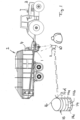
- eine schematische Gesamtansicht einer Vorrichtung zum Erfassen des Verschleißzustandes der Verschleißteile an einem landwirtschaftlichen Gerät in Form eines Ladewagens,
- Fig. 2:
- eine perspektivische Darstellung des Schneidmesserbalkens des Ladewagens aus
Fig. 1 bei der photographischen Verschleißerfassung der Messer, und - Fig. 3:
- das mit Hilfe der Kamera des mobilen Endgeräts erfasste Ist-Bild eines Schneidmessers des Ladewagens aus
Fig. 1 und mehrere Referenzschadensbilder des Schneidmessers, die verschiedene Verschleißzustände zeigen. - Wie die
Figuren 1 bis 3 zeigen, kann beispielsweise der Verschleißzustand von Verschleißteilen eines landwirtschaftlichen Geräts in Form eines Ladewagens bestimmt werden, wobei das Bauteil 1, dessen Verschleiß bestimmt werden soll, beispielsweise die Messer des Ladewagens sein können, mit denen das vom Boden aufgenommene Erntegut zerschnitten wird, bevor es in den Laderaum des Ladewagens gefördert wird. - Wie
Fig. 1 zeigt, kann die landwirtschaftliche Maschine 2 beispielsweise in Form des Ladewagens als Anbaugerät ausgebildet sein, das von einem Schlepper gezogen oder geschoben wird und gesteuert werden kann, wobei die landwirtschaftliche Maschine 2 oder auch der zugehörige Schlepper 3 eine Datenverarbeitungsvorrichtung 4, beispielsweise in Form eines Jobrechners, aufweisen kann, um Betriebsdaten der Maschine 2 zu sammeln. Beispielsweise kann die Datenverarbeitungsvorrichtung 4 über eine geeignete Sensorik Betriebsdaten, wie beispielsweise die Flächenleistung, die Anzahl der Fuhren oder die Menge des aufgenommenen Ernteguts erfasst und gespeichert werden, wobei diese gespeicherten Maschinenbetriebsdaten über einen Kommunikationsbaustein der Datenverarbeitungsvorrichtung 4 auf ein mobiles Endgerät 10 des Endnutzers übertragen werden kann. - Beispielsweise kann an der landwirtschaftlichen Maschine 2 ein so genannter Beacon, also ein Funksender, oder auch eine andere Sendeeinrichtung vorgesehen sein, um die Maschinenbetriebsdaten auf das mobile Endgerät 10 zu übertragen. Beispielsweise kann auch ein Transponder oder insbesondere auch eine Bluetooth-Einrichtung vorgesehen werden, die mit dem mobilen Endgerät 10 kommunizieren kann.
- Das mobile Endgerät 10 kann insbesondere als Mobiltelefon, vorzugsweise in Form eines Smartphones, aber auch als Tablet-Computer ausgebildet sein.
- Das mobile Endgerät 10 weist insbesondere eine Datenkommunikationseinrichtung 11 sowie eine optische Erfassungseinrichtung 12, vorzugsweise in Form einer Kamera 13 auf, um einerseits Daten, einschließlich Bilddaten, übertragen zu können, wobei die Datenkommunikationseinrichtung 11 beispielsweise eine Mobilfunkeinrichtung 12 umfassen kann. Die Datenkommunikationseinrichtung 11 umfasst vorteilhafterweise auch die vorgenannte Bluetooth-Einrichtung oder eine Einrichtung, um die Funksignale des Beacons der Maschine 2 empfangen zu können, wobei hierfür eine Nahfeld-Kommunikationseinrichtung ausreichend sein kann.
- Wie
Fig. 1 verdeutlicht, kann das mobile Endgerät 10 insbesondere mit einer separaten Rechnereinheit, beispielsweise in Form eines Servers, und/oder einer Datencloud kommunizieren, wie noch erläutert wird. - Um den Verschleißzustand eines Bauteils 1, beispielsweise der Schneidmesser, der landwirtschaftlichen Maschine 2 zu bestimmen, nimmt der Endnutzer mit der Kamera 13 des mobilen Endgeräts 10 zunächst zumindest ein Foto des Bauteils 1 auf, das eine Ist-Darstellung bzw. ein Ist-Bild des Bauteils 1 darstellt. Wie
Fig. 2 zeigt, kann beispielsweise der die Messer tragende Messerbalken herausschwenkbar sein, um Zugang zu den Messern zu haben, was an sich dem Austausch oder dem Schleifen der Messer dient, gleichzeitig aber den Blick auf die Messer freigibt, um ein Bild aufzunehmen. - Um das Ist-Bild des Bauteils 1 aus der richtigen Perspektive und/oder aus der richtigen Entfernung aufzunehmen, kann das mobile Endgerät 10 vorteilhafterweise eine Aufnahmeführungs-Einrichtung 5 umfassen, die Teil einer auf dem Endgerät 10 implementierbaren App, bzw. eines entsprechenden Software-Bausteins sein kann, der Anweisungen zur Perspektive und/oder zum Abstand für die Aufnahme des Ist-Bilds ausgeben kann. Solche Aufnahmeanweisungen können mit der Identifikation des zu bearbeitenden Bauteils 1 verknüpft sein, um bauteilspezifische, individuelle Aufnahmeanweisungen ausgeben zu können.
- Hierfür kann es sinnvoll sein wenn vor der Aufnahme des Ist-Bilds das Bauteil 1 identifiziert wird, was beispielsweise über eine manuelle Eingabe über die Dateneingabevorrichtung des mobilen Endgeräts 1 erfolgen kann, beispielsweise über dessen Touchscreen und/oder dessen Tastatur. Hierfür kann die genannten Aufnahmeführung 5 zunächst eine Eingabeaufforderung anzeigen, beispielsweise "welches Bauteil", woraufhin der Endnutzer die Eingabe "Schneidmesser" eingeben kann, gegebenenfalls auch über einen Spracheingabebefehl. Alternativ oder zusätzlich kann der Identifikationsbaustein 6 zum Identifizieren des Bauteils 1 auch einen Codeleser umfassen, mittels dessen ein am Bauteil angebrachter Code, beispielsweise in Form eines Strichcodes oder eines VR-Codes, eingelesen werden kann.
- Ist das Bauteil 1 identifiziert - im vorliegenden Fall also das Schneidmesser - kann die Aufnahmeführungs-Einrichtung 5 entsprechende Anweisungen für die Aufnahme des Ist-Bilds bereitstellen, was beispielsweise grafisch auf dem Display des Endgeräts 10 oder akustisch über dessen Lautsprecher erfolgen kann.
- Die genannten Aufnahmeführungs-Anweisungen können dabei auf dem mobilen Endgerät 10 selbst gespeichert sei. Alternativ oder zusätzlich kann das mobile Endgerät 10 hierfür auch mit dem genannten separaten Rechner 16 kommunizieren, um dort aus einer Datenbank die Aufnahmeführungs-Anweisungen abzurufen, die für das entsprechende Bauteil dort hinterlegt sein können.
- Die genannten Bilddaten, die vom mobilen Endgerät 10 aufgenommen werden, können insbesondere an eine zentrale Datencloud übertragen werden, mit der das Endgerät 10 kommunizieren kann. Alternativ oder zusätzlich kann das mobile Endgerät aus der besagten Datencloud auch Daten abrufen und/oder erhalten und/oder in Form von ausgewerteten Bilddaten bzw. daraus abgeleiteten Verschleißdaten zur Anzeige auf dem mobilen Endgerät. Insbesondere können sämtliche Daten, auch die Referenzbilder und/oder Maschinenidentifikationsdaten und/oder Aufnahmeführungs-Anweisungen, Verschleißkurven oder einzelne Verschleißzustandsdaten in der besagten Cloud abgelegt werden.
- Hat der Endnutzer unter Berücksichtigung der Aufnahmeführung das Ist-Bild mit der Kamera 13 am mobilen Endgerät 10 gemacht, übermittelt das mobile Endgerät 10 die Bilddaten des Ist-Bilds an eine Auswerteeinheit 15, die das Ist-Bild auswertet. Die genannte Auswerteeinheit 15 kann am mobilen Endgerät 10 selbst vorgesehen sein, beispielsweise in Form eines dort implementierten Software-Bausteins. Alternativ oder zusätzlich kann die Auswerteeinheit 15 aber auch an der separaten Rechnereinheit 16 vorgesehen sein, beispielsweise in Form eines dort implementierten Software-Bausteins, um das Ist-Bild des Bauteils 1 hinsichtlich seines Verschleißes auszuwerten.
- Insbesondere kann die genannte Auswerteeinheit 15 eine Bildauswerteeinrichtung 14 umfassen, die das Ist-Bild mit einem oder mehreren Referenzbildern des Bauteils 1 vergleicht, die charakteristische Zustände des Bauteils 1 wiedergeben. Insbesondere kann das Ist-Bild mit zumindest einem Referenzbild verglichen werden, das den unverschlissenen Neuzustand des Bauteils 1 zeigt und/oder zumindest mit einem Referenzbild verglichen werden, das einen bestimmten Verschleißzustand, beispielsweise 50 % Verschleiß oder 75 % Verschleiß des Bauteils 1 zeigt.
-
Fig. 3 zeigt solche Referenzbilder des Bauteils 1 - in Form des schon genannten Schneidmessers - wobei diese Referenzbilder in einem Referenzbildspeicher 17 gespeichert sein können, der Teil der Rechnereinheit 16 sein oder auf den die Rechnereinheit 16 Zugriff haben kann. Gegebenenfalls können solche Referenzbilder aber auch in dem mobilen Endgerät 10 selbst gespeichert werden. - Wie
Fig. 3 zeigt, kann es sinnvoll sein, als Referenzbilder mehrere Verschleißstufen zu haben, die im Verschleißgrad stufenweise zwischen dem Neuzustand und dem Verschleißzustand, in dem die zulässige Verschleißgrenze erreicht ist, liegen können. - Die genannte Bildauswerteeinrichtung 14 vergleicht das Ist-Bild des Bauteils 1 anhand verschiedener Kriterien mit den gespeicherten Referenzbildern, um zu bestimmen, welchem der Referenzbilder das Ist-Bild am nächsten kommt, bzw. zwischen welchen Referenzbildern und damit zwischen welchen Verschleißgraden das Ist-Bild liegt.
- Die Bildauswerteeinrichtung 14 kann verschiedene Auswertekriterien berücksichtigen und beispielsweise Konturauswertemittel 14a umfassen, die Konturveränderungen des Bauteils 1 bestimmen können, um anhand solcher Konturveränderungen den Verschleißzustand bestimmen zu können. Insbesondere können solche Konturauswertemittel 14a Umrissverkleinerungen und/oder Bauteilverdünnungen bestimmen, um anhand der eingetretenen Umrissverkleinerung und/oder der eingetretenen Bauteilverdünnung den Verschleißgrad zu bestimmen.
- Alternativ oder zusätzlich können die Konturauswertemittel 14a auch Unregelmä-ßigkeiten und/oder Wellungen und/oder Vertiefungen, wie Schrammen oder Erhöhungen, wie Blasen an der Bauteiloberfläche bestimmen, um anhand solcher Oberflächen- und/oder Umrisskonturwellungen den Verschleiß zu bestimmen. Beispielsweise bei den gezeigten Schneidmessern führen aufschlagende Steine regelmäßig zu Eindellungen an der Schneide, so dass die Schneide nicht mehr die ursprüngliche, oft strakende, harmonische Kontur besitzt, sondern darin charakteristische Eindellungen besitzt, welche als Verschleiß identifiziert werden können.
- Ferner kann die Bildauswerteeinrichtung 14 Farbmuster- und/oder Graustufenmuster-Auswertemittel 14b umfassen, die anhand des Bildvergleichs Veränderungen des Farbmusters und/oder des Graustufenmusters, welches das Bauteil 1 im aufgenommenen Bild zeigt, bestimmen und daraus den Verschleißgrad ermitteln können.
- Ferner kann die Bildauswerteeinrichtung 14 auch Flächenanteils-Auswertemittel 14c umfassen, die in einem umfassten Bild des Bauteils 1 den Flächenanteil einer jeweiligen Farbe und/oder einer jeweiligen Graustufe und/oder eines jeweiligen Pixelmusters bestimmen können, welchen Flächenanteil die genannte Farbe und/oder Graustufe und/oder Pixelagglomeration in der Gesamtfläche des Bauteils 1 einnimmt. Hat beispielsweise das Messer als Schneide einen Wellenschliff, der als zebraähnliches Hell-Dunkelmuster an einer Kante des Messers bzw. des Bildes hiervon erscheint, kann die Flächenanteils-Auswertung bestimmen, welchen Flächenanteil das genannte Zebramuster und damit der Wellenschliff an der Gesamtfläche des Messers besitzt, woraus wiederum auf den Verschleißgrad geschlossen werden kann. Nutzt sich die Schneide zunehmend ab, wird der Wellenschliffanteil und damit das Zebramuster in seinem Anteil an der Gesamtfläche des Messers kleiner.
- Die genannten Farbflächenanteil- und/oder Graustufenflächenanteil-Auswertemittel 14c können auch das Auftreten einer neuen Farbe und deren Flächenanteil bestimmen. Tritt beispielsweise an einem Bauteil mit dunkler Oberflächenbeschichtung der metallisch-silbrige Kern mit einem immer größeren Flächenanteil zu Tage, weil die dunkle Oberflächenbeschichtung zunehmend verschleißt, kann der Flächenanteil des metallisch-silbrigen Kerns im Verhältnis zur dunklen Oberflächenbeschichtung ein Maß für die Abnutzung und den Verschleiß bilden.
- Die Bildauswerteeinrichtung 14 kann auch Verformungs-Auswertemittel 14d umfassen, um anhand des Vergleichs des Ist-Bilds mit den Referenzbildern eine Verformung des Bauteils 1 zu bestimmen. Zeigt beispielsweise ein Ist-Bild des Schneidmessers, welches frontal von vorne auf die Schneide aufgenommen wurde, keine schmale, ebene Schneidplatte, sondern ein mehr oder minder stark bogenförmig gekrümmtes Blech, kann aus dem Vergleich mit den Referenzbildern, die eine unverformte, ebene Schneidplatte zeigen, eine Verformung des Messers bestimmt und daraus der Verschleißgrad ermittelt werden.
- Vorteilhafterweise kann die Auswerteeinheit 15 zusätzlich zu der genannten Bildauswertung auch noch weitere Bauteilinformationen für die Bestimmung des Verschleißzustandes heranziehen und zwar insbesondere die zuvor genannten Betriebsdaten des Bauteils, wie beispielsweise die Flächenleistung, die Fuhrenzahl, die Betriebsstunden oder die Fuhrenzahl, die von der Datenverarbeitungsvorrichtung 4 der Maschine 2 erfasst und gespeichert und von der Kommunikationseinrichtung, beispielsweise in Form des genannten Beacons auf das mobile Endgerät 10 übertragen worden sind.
- In der eingangs schon erläuterten Weise können diese Betriebsdaten zusätzlich zu dem Verschleißgrad, der aus der Bildauswertung bestimmt wurde, berücksichtigt und gegebenenfalls gewichtet werden, um den endgültigen Verschleißgrad zu bestimmen.
Claims (16)
- Vorrichtung zum Erkennen des Verschleißzustands eines Verschleißteils einer landwirtschaftlichen Maschine,wobei die Vorrichtung ein mobiles Endgerät (10) und eine Datenverarbeitungsvorrichtung (4) der landwirtschaftlichen Maschine umfasst,wobei das mobile Endgerät (10) eine optische Erfassungseinrichtung (12), insbesondere eine Kamera (13), zum Erfassen des Ist-Bilds des Bauteils (1),eine Datenkommunikationseinrichtung (11), undeine Auswerteeinheit (15) mit einer Bildauswerteeinheit (14) sowie einem Referenzbildspeicher (17), in dem zumindest eine Referenzdarstellung des Bauteils (1) gespeichert ist, umfasst,
wobei die Bildeauswerteeinrichtung (14) dazu ausgebildet ist, das Ist-Bild des Bauteils (1) mit dem zumindest einen Referenzbild des Bauteils (1) zu vergleichen und durch den optischen Vergleich den Schädigungs- und/oder Verschleißgrad des Bauteils (1) zu bestimmen,wobei von der Datenverarbeitungsvorrichtung (4) der landwirtschaftlichen Maschine (2), an dem das Bauteil (1) verwendet wird, Betriebsdaten an das mobile Endgerät übertragbar sind, wobeidie Auswerteeinheit (15) Auswertemittel zum Auswerten der von dem mobilen Endgerät (10) an die Auswerteeinheit (15) übertragen Betriebsdaten umfasst, unddie genannten Auswertemittel eine Schätzeinrichtung zum Abschätzen des Verschleißzustands des Bauteils (1) anhand der übermittelten Betriebsdaten umfassen, undwobei die Auswerteeinheit (15) dazu ausgebildet ist, anhand des auf Basis der übermittelten Betriebsdaten geschätzten Verschleißzustands und des von der Bildauswerteeinrichtung (14) anhand des Bildvergleichs ermittelten Verschleißzustands einen endgültigen Verschleißzustand zu bestimmen. - Vorrichtung nach dem vorhergehenden Anspruch, wobei der Referenzbildspeicher (17) einen Referenzschädigungsspeicher aufweist, in dem Referenzdarstellungen des Bauteils (1) mit verschiedenen Schädigungsgraden des Bauteils (1) enthalten sind, anhand derer durch einen optischen Vergleich des Ist-Bilds des Bauteils mit den gespeicherten Referenzdarstellungen der Schädigungs- und/oder Verschleißgrad des Bauteils bestimmbar ist.
- Vorrichtung nach einem der vorhergehenden Ansprüche, wobei eine automatische oder halbautomatische Bildauswerteeinrichtung (14) zum optischen Vergleichen des Ist-Bilds des Bauteils (1) mit den gespeicherten Referenzdarstellungen und zum Einkategorisieren von im Ist-Bild zu sehenden Schädigungen vorgesehen ist.
- Vorrichtung nach einem der vorhergehenden Ansprüche, wobei eine Auswerteeinrichtung (14) zum Aufsummieren von einzelnen Schädigungen zu einem Gesamtschädigungsgrad und Abgeben eines Austauschreifesignals bei Erreichen eines vorbestimmten Gesamtschädigungsgrades vorgesehen ist.
- Vorrichtung nach einem der vorhergehenden Ansprüche, wobei die optische Erfassungseinrichtung (12) dazu ausgebildet ist, farbige Ist-Bilder des Bauteils (1) zu erfassen, wobei die Bildauswerteeinrichtung (14) dazu vorgesehen ist, Schädigungen des Bauteils anhand unterschiedlicher Farben, in denen Abschnitte und/oder Materialschichten des Bauteils (1) eingefärbt sind, zu erfassen und einzukategorisieren.
- Vorrichtung nach einem der vorhergehenden Ansprüche, wobei die Bildauswerteeinrichtung (14) dazu ausgebildet ist, anhand verschiedener Werkstoffe, aus denen das Bauteil besteht, Schädigungen zu erfassen und einzukategorisieren.
- Vorrichtung nach einem der vorhergehenden Ansprüche, wobei die Bildauswerteeinrichtung (14) Konturauswertemittel (14a) zum Bestimmen von Konturveränderungen des Bauteils (1), und Bestimmen des Verschleißzustands anhand solcher Konturveränderungen aufweist, wobei die Konturauswertemittel (14a) dazu ausgebildet sind,Umrißverkleinerungen und/oder Bauteilverdünnungen zu bestimmen, und den Verschleißzustand anhand solcher Umrißverkleinerungen und/oder Bauteilverdünnungen zu bestimmen, und/oderOberflächen- und/oder Umrißkonturwellungen des Bauteils (1) zu bestimmen, und den Verschleißzustand anhand der Oberflächen- und/oder Umrißkonturwellungen zu bestimmen.
- Vorrichtung nach einem der vorhergehenden Ansprüche, wobei die Bildauswerteeinrichtung (14)Farb- und/oder Graustufenmuster-Auswertemittel (14b) zum Bestimmen von Veränderungen des Farb- und/oder Graustufenmusters des Bauteils (1) und Bestimmen der Ablegereife anhand eines festgestellten, veränderten Farb- und/oder Graustufenmusters, und/oderFarb- und/oder Graustufenflächenanteil-Auswertemittel (14c) zum Bestimmen des Flächenanteils einer Farbe und/oder Graustufe im Bild des Bauteils (1) und Bestimmen der Ablegereife anhand des festgestellten Farb- und/oder Graustufenflächenanteils aufweist.
- Vorrichtung nach einem der vorhergehenden Ansprüche, wobei die Bildauswerteeinrichtung (14) Verformungs-Auswertemittel (14d) zum optischen Bestimmen der Beabstandung und Relativposition bestimmter Farbmuster- und/oder Pixelgruppenstellen im Bild des Bauteils (1) und Bestimmen einer Bauteilverformung anhand der festgestellten Beabstandung und Relativposition sowie schließlich Bestimmen des Verschleißzustands anhand der festgestellten Bauteilverformung aufweist.
- Vorrichtung nach einem der vorhergehenden Ansprüche, wobei eine Aufnahmeführungs-Einrichtung (5) zum Ausgeben von Anweisungen zur Perspektive, aus der das Ist-Bild des Bauteils (1) aufzunehmen ist, an dem mobilen Endgerät (10) vorgesehen ist.
- Vorrichtung nach dem vorhergehenden Anspruch, wobei die Aufnahmeführungs-Einrichtung (5) dazu ausgebildet ist, bauteilspezifische Aufnahmeanweisungen, die von Bauteil zu Bauteil variieren, auszugeben und in Abhängigkeit einer Bauteil-Identifikation arbeitet.
- Vorrichtung nach einem der vorhergehenden Ansprüche, wobei eine Identifikations-Einrichtung (6) zum Identifizieren des Bauteils (1) an dem mobilen Endgerät (10) vorgesehen ist, wobei die Identifikations-Einrichtung (6) einen CodeLeser zum Einlesen eines Bauteilcodes, insbesondere eines Strichcodes und/oder eines HR-Codes und/oder eines Zahlencodes, aufweist, anhand dessen das Bauteil identifizierbar ist.
- Vorrichtung nach einem der vorhergehenden Ansprüche, wobei die Auswerteeinheit (15) einen Verschleißkurven-Bestimmungsbaustein zum Bestimmen einer Verschleißkurve aus mehreren, zeitlich nacheinander von der Bildauswerteeinrichtung (14) bestimmten Schädigungs- und/oder Verschleißgraden des Bauteils (1) und Berechnen der verbleibenden Restlebensdauer aus der Verschleißkurve aufweist.
- Vorrichtung nach einem der vorhergehenden Ansprüche, wobei eine Cloud zum Speichern der zumindest einen Referenzdarstellung und/oder des zumindest einen erfassten Ist-Bilds des Bauteils und/oder weiterer Daten für die Verschleißbestimmung vorgesehen ist.
- Vorrichtung nach einem der vorhergehenden Ansprüche, wobei die Betriebsdaten erbrachte Flächenleistung, Betriebsstunden, Fuhrenanzahl und/oder Ballenanzahl sind.
- Verfahren zum Bestimmen des Verschleißzustands eines Verschleißteils einer landwirtschaftlichen Maschine (1), wobei mit der optischen Erfassungseinrichtung (12) eines mobilen Endgeräts (10) ein Ist-Bild des Bauteils (1) erfasst wird, wobei in einem Referenzbildspeicher (17) zumindest ein Referenzbild des Bauteils (1) bereitgehalten wird, wobei von einer Auswerteeinheit (15) mit einer Bildauswerteeinrichtung (14) das erfasste Ist-Bild des Bauteils (1) mit dem gespeicherten Referenzbild verglichen und aus dem Bildvergleich der Schädigungs- und/oder Verschleißzustand des Bauteils (1) automatisch ermittelt wird, wobei von einer Datenverarbeitungsvorrichtung (4) der landwirtschaftlichen Maschine (2), an der das Bauteil (1) verwendet wird, Betriebsdaten an das mobile Endgerät (10) übertragen werden, wobei die genannte Auswerteeinheit (15) mit Auswertemitteln, die von dem mobilen Endgerät (10) an die Auswerteeinheit (15) übertragenen Betriebsdaten auswertet und mittels einer Schätzeinrichtung der Auswertemittel den Verschleißzustand des Bauteils anhand der übermittelten Betriebsdaten abschätzt, und wobei von der genannten Auswerteeinheit (15) anhand des auf Basis der übermittelten Betriebsdaten geschätzten Verschleißzustands und des von der Bildauswerteeinrichtung (14) anhand des Bildvergleichs ermittelten Verschleißzustands ein endgültiger Verschleißzustand bestimmt wird.
Applications Claiming Priority (1)
| Application Number | Priority Date | Filing Date | Title |
|---|---|---|---|
| DE102018121997.0A DE102018121997A1 (de) | 2018-09-10 | 2018-09-10 | Verfahren und Vorrichtung zur Verschleißerkennung eines Bauteils für landwirtschaftliche Geräte |
Publications (2)
| Publication Number | Publication Date |
|---|---|
| EP3636063A1 EP3636063A1 (de) | 2020-04-15 |
| EP3636063B1 true EP3636063B1 (de) | 2023-08-30 |
Family
ID=67438652
Family Applications (1)
| Application Number | Title | Priority Date | Filing Date |
|---|---|---|---|
| EP19187980.8A Active EP3636063B1 (de) | 2018-09-10 | 2019-07-24 | Verfahren und vorrichtung zur verschleisserkennung eines bauteils für landwirtschaftliche geräte |
Country Status (2)
| Country | Link |
|---|---|
| EP (1) | EP3636063B1 (de) |
| DE (1) | DE102018121997A1 (de) |
Families Citing this family (10)
| Publication number | Priority date | Publication date | Assignee | Title |
|---|---|---|---|---|
| DE102020128759B4 (de) | 2020-11-02 | 2024-09-05 | Technische Universität Dresden, Körperschaft des öffentlichen Rechts | Softwareverfahren zur opto-sensorischen Erkennung, Vermessung und Bewertung von Werkzeugzuständen |
| CN112508107B (zh) * | 2020-12-10 | 2024-07-26 | 中国人民解放军32181部队 | 一种装备状态感知方法和系统 |
| CN113269746A (zh) * | 2021-05-23 | 2021-08-17 | 东台升华工具有限公司 | 一种利用图像识别的钻头磨损检测方法 |
| CN114463566B (zh) * | 2022-02-28 | 2026-02-24 | 北京梧桐车联科技有限责任公司 | 车辆安全等级的确定方法、装置、设备及可读存储介质 |
| DE102022110117A1 (de) * | 2022-04-27 | 2023-11-02 | Claas Selbstfahrende Erntemaschinen Gmbh | Verfahren zum Bestimmen eines Verschleißzustands einer autonomen landwirtschaftlichen Arbeitsmaschine |
| CN114882028B (zh) * | 2022-07-08 | 2022-10-21 | 深圳市瑞祥鑫五金制品有限公司 | 一种基于多摄像头的焊接端子检测方法、装置及系统 |
| US20240196771A1 (en) * | 2022-12-19 | 2024-06-20 | Cnh Industrial Canada, Ltd. | System and method for monitoring plugging of basket assemblies of an agricultural implement |
| DE102023106996A1 (de) * | 2023-03-21 | 2024-09-26 | Lemken Gmbh & Co. Kg | Verfahren zur Zustandserkennung von Bodenbearbeitungswerkzeugen an einem Bodenbearbeitungsgerät |
| CN116804597B (zh) * | 2023-08-22 | 2023-12-15 | 梁山华鲁专用汽车制造有限公司 | 挂车连接状态检测装置及检测方法 |
| CN117150685B (zh) * | 2023-10-26 | 2024-02-06 | 国合通用(青岛)测试评价有限公司 | 一种紧固螺栓的疲劳寿命评估系统及方法 |
Family Cites Families (13)
| Publication number | Priority date | Publication date | Assignee | Title |
|---|---|---|---|---|
| JP3133226B2 (ja) * | 1995-02-15 | 2001-02-05 | 株式会社日立製作所 | プラント構造材料の腐食推定方法、および腐食診断システム |
| GB2414616A (en) * | 2004-05-28 | 2005-11-30 | Sony Uk Ltd | Comparing test image with a set of reference images |
| US8526705B2 (en) * | 2009-06-10 | 2013-09-03 | Apple Inc. | Driven scanning alignment for complex shapes |
| CN102639958A (zh) * | 2010-02-10 | 2012-08-15 | 株式会社小松制作所 | 磨损量测定装置、磨损量测定方法、磨损量测定程序及记录介质 |
| GB2489253B (en) * | 2011-03-22 | 2014-08-13 | Ev Offshore Ltd | Corrosion assessment apparatus and method |
| US9613413B2 (en) * | 2012-10-17 | 2017-04-04 | Caterpillar Inc. | Methods and systems for determining part wear based on digital image of part |
| US10169858B2 (en) * | 2013-03-12 | 2019-01-01 | FedEx Supply Chain Logistics & Electronics, Inc. | System and method for automated cosmetic inspection of electronic devices |
| US9786042B2 (en) * | 2015-01-29 | 2017-10-10 | Honeywell International Inc. | Algorithm for measuring wear pin length using an input image |
| US9971991B2 (en) | 2015-04-28 | 2018-05-15 | Accenture Global Services Limited | Automated, new spare parts forecasting and demand planning system |
| JP6423769B2 (ja) * | 2015-08-31 | 2018-11-14 | ファナック株式会社 | 加工精度維持機能を有する加工システム |
| US10732620B2 (en) * | 2016-08-01 | 2020-08-04 | General Electric Company | System and method for inspecting machinery |
| EP3326749B2 (de) * | 2016-11-26 | 2025-11-12 | Agie Charmilles SA | Verfahren zur bearbeitung und prüfung von werkstücken |
| US20180159468A1 (en) * | 2016-12-01 | 2018-06-07 | Bt Imaging Pty Ltd | Determining the condition of photovoltaic modules |
-
2018
- 2018-09-10 DE DE102018121997.0A patent/DE102018121997A1/de active Pending
-
2019
- 2019-07-24 EP EP19187980.8A patent/EP3636063B1/de active Active
Also Published As
| Publication number | Publication date |
|---|---|
| DE102018121997A1 (de) | 2020-03-12 |
| EP3636063A1 (de) | 2020-04-15 |
Similar Documents
| Publication | Publication Date | Title |
|---|---|---|
| EP3636063A1 (de) | Verfahren und vorrichtung zur verschleisserkennung eines bauteils für landwirtschaftliche geräte | |
| EP3299996B1 (de) | Landwirtschaftliche arbeitsmaschinen mit bildverarbeitungssystem | |
| EP2918159A1 (de) | Anordnung und Verfahren zur Erkennung und Dokumentation von Strohqualität | |
| EP3626041A1 (de) | Landwirtschaftliches arbeitssysstem | |
| DE102017119968A1 (de) | System zur Identifikation eines Anhängers und zur Unterstützung eines Ankupplungsprozesses an eine Zugmaschine | |
| DE102016118227A1 (de) | Bildanlysesystem für landwirtschaftliche Arbeitsmaschinen | |
| EP3456167A1 (de) | Landwirtschaftliche arbeitsmaschine | |
| DE102008057461A1 (de) | Anzeigeeinheit | |
| DE112012001901T5 (de) | Arbeitsmaschine und Wartungs- und Inspektions-Informations-Erzeugungsvorrichtung | |
| EP3482975A1 (de) | Raupenfahrzeug | |
| EP3409088B1 (de) | Vorrichtung zum aufzeichnen von fahrwegdaten eines landwirtschaftlichen arbeitsgeräts | |
| DE102011015849A1 (de) | Vorrichtung und Verfahren zur automatischen Überwachung einer Vorrichtung zur Verarbeitung von Fleischprodukten | |
| DE102020129795A1 (de) | Feldhäcksler mit Konditionierwalzen und Verschleißsensor | |
| EP2329705A1 (de) | Häckselmesser für einen Feldhäcksler und Anordnung zur Erfassung von dessen Schärfe | |
| EP3861849B1 (de) | Landwirtschaftliche arbeitsmaschine mit einer messanordnung, messanordnung für die landwirtschaftliche arbeitsmaschine und verfahren zum messen einer kontur eines sich bewegenden bauteils der landwirtschaftlichen arbeitsmaschine | |
| EP4091435A1 (de) | Verfahren zur bestimmung des schleifbedarfs von häckselmessern einer häckselvorrichtung | |
| DE102017127648B3 (de) | Landwirtschaftsmaschine sowie Verfahren zum Betreiben einer solchen Maschine | |
| EP2395405B1 (de) | System und Verfahren zur Überwachung von Werkzeugen | |
| EP4331344B1 (de) | Verfahren zum bestimmen eines verschleisszustands einer selbstfahrenden landwirtschaftlichen erntemaschine | |
| DE102022100172A1 (de) | Informationsverarbeitungsvorrichtung, Arbeitsverwaltungssystem und Arbeitsverwaltungsverfahren | |
| DE102020207078A1 (de) | Steuerungsverfahren zur zumindest teilautonomen Verdichtung von Silage | |
| EP3258431A1 (de) | Verfahren zur zustandsakquisition einer landwirtschaftlichen arbeitseinheit | |
| EP2857919B1 (de) | System zum Steuern des Betriebs eines landwirtschaftlichen Nutzfahrzeugs | |
| DE10225098A1 (de) | Verfahren zur Erstellung eines Schnitthöhen-Protokolls im laufenden Arbeitsprozess von Erntemaschinen | |
| DE102022129369A1 (de) | Höhenführung für ein Schnittsystem, Schnittsystem und Verfahren zur Höhenführung eines solchen Schnittsystems |
Legal Events
| Date | Code | Title | Description |
|---|---|---|---|
| PUAI | Public reference made under article 153(3) epc to a published international application that has entered the european phase |
Free format text: ORIGINAL CODE: 0009012 |
|
| STAA | Information on the status of an ep patent application or granted ep patent |
Free format text: STATUS: THE APPLICATION HAS BEEN PUBLISHED |
|
| AK | Designated contracting states |
Kind code of ref document: A1 Designated state(s): AL AT BE BG CH CY CZ DE DK EE ES FI FR GB GR HR HU IE IS IT LI LT LU LV MC MK MT NL NO PL PT RO RS SE SI SK SM TR |
|
| AX | Request for extension of the european patent |
Extension state: BA ME |
|
| STAA | Information on the status of an ep patent application or granted ep patent |
Free format text: STATUS: REQUEST FOR EXAMINATION WAS MADE |
|
| 17P | Request for examination filed |
Effective date: 20201009 |
|
| RBV | Designated contracting states (corrected) |
Designated state(s): AL AT BE BG CH CY CZ DE DK EE ES FI FR GB GR HR HU IE IS IT LI LT LU LV MC MK MT NL NO PL PT RO RS SE SI SK SM TR |
|
| STAA | Information on the status of an ep patent application or granted ep patent |
Free format text: STATUS: EXAMINATION IS IN PROGRESS |
|
| 17Q | First examination report despatched |
Effective date: 20220114 |
|
| GRAP | Despatch of communication of intention to grant a patent |
Free format text: ORIGINAL CODE: EPIDOSNIGR1 |
|
| STAA | Information on the status of an ep patent application or granted ep patent |
Free format text: STATUS: GRANT OF PATENT IS INTENDED |
|
| RIC1 | Information provided on ipc code assigned before grant |
Ipc: G06T 7/12 20170101ALI20230306BHEP Ipc: G06T 7/00 20060101ALI20230306BHEP Ipc: G01N 21/88 20060101ALI20230306BHEP Ipc: G01N 21/95 20060101ALI20230306BHEP Ipc: G01B 11/24 20060101ALI20230306BHEP Ipc: A01B 33/12 20060101ALI20230306BHEP Ipc: A01B 76/00 20060101AFI20230306BHEP |
|
| INTG | Intention to grant announced |
Effective date: 20230322 |
|
| GRAS | Grant fee paid |
Free format text: ORIGINAL CODE: EPIDOSNIGR3 |
|
| P01 | Opt-out of the competence of the unified patent court (upc) registered |
Effective date: 20230613 |
|
| GRAA | (expected) grant |
Free format text: ORIGINAL CODE: 0009210 |
|
| STAA | Information on the status of an ep patent application or granted ep patent |
Free format text: STATUS: THE PATENT HAS BEEN GRANTED |
|
| AK | Designated contracting states |
Kind code of ref document: B1 Designated state(s): AL AT BE BG CH CY CZ DE DK EE ES FI FR GB GR HR HU IE IS IT LI LT LU LV MC MK MT NL NO PL PT RO RS SE SI SK SM TR |
|
| REG | Reference to a national code |
Ref country code: GB Ref legal event code: FG4D Free format text: NOT ENGLISH |
|
| REG | Reference to a national code |
Ref country code: CH Ref legal event code: EP |
|
| REG | Reference to a national code |
Ref country code: DE Ref legal event code: R096 Ref document number: 502019009120 Country of ref document: DE |
|
| REG | Reference to a national code |
Ref country code: IE Ref legal event code: FG4D Free format text: LANGUAGE OF EP DOCUMENT: GERMAN |
|
| REG | Reference to a national code |
Ref country code: NL Ref legal event code: FP |
|
| REG | Reference to a national code |
Ref country code: LT Ref legal event code: MG9D |
|
| PG25 | Lapsed in a contracting state [announced via postgrant information from national office to epo] |
Ref country code: GR Free format text: LAPSE BECAUSE OF FAILURE TO SUBMIT A TRANSLATION OF THE DESCRIPTION OR TO PAY THE FEE WITHIN THE PRESCRIBED TIME-LIMIT Effective date: 20231201 |
|
| PG25 | Lapsed in a contracting state [announced via postgrant information from national office to epo] |
Ref country code: IS Free format text: LAPSE BECAUSE OF FAILURE TO SUBMIT A TRANSLATION OF THE DESCRIPTION OR TO PAY THE FEE WITHIN THE PRESCRIBED TIME-LIMIT Effective date: 20231230 |
|
| PG25 | Lapsed in a contracting state [announced via postgrant information from national office to epo] |
Ref country code: SE Free format text: LAPSE BECAUSE OF FAILURE TO SUBMIT A TRANSLATION OF THE DESCRIPTION OR TO PAY THE FEE WITHIN THE PRESCRIBED TIME-LIMIT Effective date: 20230830 Ref country code: RS Free format text: LAPSE BECAUSE OF FAILURE TO SUBMIT A TRANSLATION OF THE DESCRIPTION OR TO PAY THE FEE WITHIN THE PRESCRIBED TIME-LIMIT Effective date: 20230830 Ref country code: NO Free format text: LAPSE BECAUSE OF FAILURE TO SUBMIT A TRANSLATION OF THE DESCRIPTION OR TO PAY THE FEE WITHIN THE PRESCRIBED TIME-LIMIT Effective date: 20231130 Ref country code: LV Free format text: LAPSE BECAUSE OF FAILURE TO SUBMIT A TRANSLATION OF THE DESCRIPTION OR TO PAY THE FEE WITHIN THE PRESCRIBED TIME-LIMIT Effective date: 20230830 Ref country code: LT Free format text: LAPSE BECAUSE OF FAILURE TO SUBMIT A TRANSLATION OF THE DESCRIPTION OR TO PAY THE FEE WITHIN THE PRESCRIBED TIME-LIMIT Effective date: 20230830 Ref country code: IS Free format text: LAPSE BECAUSE OF FAILURE TO SUBMIT A TRANSLATION OF THE DESCRIPTION OR TO PAY THE FEE WITHIN THE PRESCRIBED TIME-LIMIT Effective date: 20231230 Ref country code: HR Free format text: LAPSE BECAUSE OF FAILURE TO SUBMIT A TRANSLATION OF THE DESCRIPTION OR TO PAY THE FEE WITHIN THE PRESCRIBED TIME-LIMIT Effective date: 20230830 Ref country code: GR Free format text: LAPSE BECAUSE OF FAILURE TO SUBMIT A TRANSLATION OF THE DESCRIPTION OR TO PAY THE FEE WITHIN THE PRESCRIBED TIME-LIMIT Effective date: 20231201 Ref country code: FI Free format text: LAPSE BECAUSE OF FAILURE TO SUBMIT A TRANSLATION OF THE DESCRIPTION OR TO PAY THE FEE WITHIN THE PRESCRIBED TIME-LIMIT Effective date: 20230830 |
|
| PG25 | Lapsed in a contracting state [announced via postgrant information from national office to epo] |
Ref country code: PL Free format text: LAPSE BECAUSE OF FAILURE TO SUBMIT A TRANSLATION OF THE DESCRIPTION OR TO PAY THE FEE WITHIN THE PRESCRIBED TIME-LIMIT Effective date: 20230830 |
|
| PG25 | Lapsed in a contracting state [announced via postgrant information from national office to epo] |
Ref country code: ES Free format text: LAPSE BECAUSE OF FAILURE TO SUBMIT A TRANSLATION OF THE DESCRIPTION OR TO PAY THE FEE WITHIN THE PRESCRIBED TIME-LIMIT Effective date: 20230830 |
|
| PG25 | Lapsed in a contracting state [announced via postgrant information from national office to epo] |
Ref country code: SM Free format text: LAPSE BECAUSE OF FAILURE TO SUBMIT A TRANSLATION OF THE DESCRIPTION OR TO PAY THE FEE WITHIN THE PRESCRIBED TIME-LIMIT Effective date: 20230830 Ref country code: RO Free format text: LAPSE BECAUSE OF FAILURE TO SUBMIT A TRANSLATION OF THE DESCRIPTION OR TO PAY THE FEE WITHIN THE PRESCRIBED TIME-LIMIT Effective date: 20230830 Ref country code: ES Free format text: LAPSE BECAUSE OF FAILURE TO SUBMIT A TRANSLATION OF THE DESCRIPTION OR TO PAY THE FEE WITHIN THE PRESCRIBED TIME-LIMIT Effective date: 20230830 Ref country code: EE Free format text: LAPSE BECAUSE OF FAILURE TO SUBMIT A TRANSLATION OF THE DESCRIPTION OR TO PAY THE FEE WITHIN THE PRESCRIBED TIME-LIMIT Effective date: 20230830 Ref country code: DK Free format text: LAPSE BECAUSE OF FAILURE TO SUBMIT A TRANSLATION OF THE DESCRIPTION OR TO PAY THE FEE WITHIN THE PRESCRIBED TIME-LIMIT Effective date: 20230830 Ref country code: CZ Free format text: LAPSE BECAUSE OF FAILURE TO SUBMIT A TRANSLATION OF THE DESCRIPTION OR TO PAY THE FEE WITHIN THE PRESCRIBED TIME-LIMIT Effective date: 20230830 Ref country code: SK Free format text: LAPSE BECAUSE OF FAILURE TO SUBMIT A TRANSLATION OF THE DESCRIPTION OR TO PAY THE FEE WITHIN THE PRESCRIBED TIME-LIMIT Effective date: 20230830 Ref country code: PT Free format text: LAPSE BECAUSE OF FAILURE TO SUBMIT A TRANSLATION OF THE DESCRIPTION OR TO PAY THE FEE WITHIN THE PRESCRIBED TIME-LIMIT Effective date: 20240102 |
|
| REG | Reference to a national code |
Ref country code: DE Ref legal event code: R097 Ref document number: 502019009120 Country of ref document: DE |
|
| PLBE | No opposition filed within time limit |
Free format text: ORIGINAL CODE: 0009261 |
|
| STAA | Information on the status of an ep patent application or granted ep patent |
Free format text: STATUS: NO OPPOSITION FILED WITHIN TIME LIMIT |
|
| PG25 | Lapsed in a contracting state [announced via postgrant information from national office to epo] |
Ref country code: SI Free format text: LAPSE BECAUSE OF FAILURE TO SUBMIT A TRANSLATION OF THE DESCRIPTION OR TO PAY THE FEE WITHIN THE PRESCRIBED TIME-LIMIT Effective date: 20230830 |
|
| 26N | No opposition filed |
Effective date: 20240603 |
|
| PGFP | Annual fee paid to national office [announced via postgrant information from national office to epo] |
Ref country code: IT Payment date: 20240627 Year of fee payment: 6 |
|
| PGFP | Annual fee paid to national office [announced via postgrant information from national office to epo] |
Ref country code: IE Payment date: 20240725 Year of fee payment: 6 |
|
| PGFP | Annual fee paid to national office [announced via postgrant information from national office to epo] |
Ref country code: AT Payment date: 20240716 Year of fee payment: 6 |
|
| PG25 | Lapsed in a contracting state [announced via postgrant information from national office to epo] |
Ref country code: BG Free format text: LAPSE BECAUSE OF FAILURE TO SUBMIT A TRANSLATION OF THE DESCRIPTION OR TO PAY THE FEE WITHIN THE PRESCRIBED TIME-LIMIT Effective date: 20230830 |
|
| PG25 | Lapsed in a contracting state [announced via postgrant information from national office to epo] |
Ref country code: BG Free format text: LAPSE BECAUSE OF FAILURE TO SUBMIT A TRANSLATION OF THE DESCRIPTION OR TO PAY THE FEE WITHIN THE PRESCRIBED TIME-LIMIT Effective date: 20230830 |
|
| PG25 | Lapsed in a contracting state [announced via postgrant information from national office to epo] |
Ref country code: MC Free format text: LAPSE BECAUSE OF FAILURE TO SUBMIT A TRANSLATION OF THE DESCRIPTION OR TO PAY THE FEE WITHIN THE PRESCRIBED TIME-LIMIT Effective date: 20230830 |
|
| REG | Reference to a national code |
Ref country code: CH Ref legal event code: PL |
|
| PG25 | Lapsed in a contracting state [announced via postgrant information from national office to epo] |
Ref country code: LU Free format text: LAPSE BECAUSE OF NON-PAYMENT OF DUE FEES Effective date: 20240724 |
|
| GBPC | Gb: european patent ceased through non-payment of renewal fee |
Effective date: 20240724 |
|
| PG25 | Lapsed in a contracting state [announced via postgrant information from national office to epo] |
Ref country code: LU Free format text: LAPSE BECAUSE OF NON-PAYMENT OF DUE FEES Effective date: 20240724 |
|
| PG25 | Lapsed in a contracting state [announced via postgrant information from national office to epo] |
Ref country code: BE Free format text: LAPSE BECAUSE OF NON-PAYMENT OF DUE FEES Effective date: 20240731 Ref country code: CH Free format text: LAPSE BECAUSE OF NON-PAYMENT OF DUE FEES Effective date: 20240731 |
|
| PG25 | Lapsed in a contracting state [announced via postgrant information from national office to epo] |
Ref country code: GB Free format text: LAPSE BECAUSE OF NON-PAYMENT OF DUE FEES Effective date: 20240724 |
|
| REG | Reference to a national code |
Ref country code: BE Ref legal event code: MM Effective date: 20240731 |
|
| PGFP | Annual fee paid to national office [announced via postgrant information from national office to epo] |
Ref country code: NL Payment date: 20250723 Year of fee payment: 7 |
|
| PGFP | Annual fee paid to national office [announced via postgrant information from national office to epo] |
Ref country code: DE Payment date: 20250724 Year of fee payment: 7 |
|
| PGFP | Annual fee paid to national office [announced via postgrant information from national office to epo] |
Ref country code: FR Payment date: 20250728 Year of fee payment: 7 |
|
| PG25 | Lapsed in a contracting state [announced via postgrant information from national office to epo] |
Ref country code: CY Free format text: LAPSE BECAUSE OF FAILURE TO SUBMIT A TRANSLATION OF THE DESCRIPTION OR TO PAY THE FEE WITHIN THE PRESCRIBED TIME-LIMIT; INVALID AB INITIO Effective date: 20190724 |
|
| PG25 | Lapsed in a contracting state [announced via postgrant information from national office to epo] |
Ref country code: HU Free format text: LAPSE BECAUSE OF FAILURE TO SUBMIT A TRANSLATION OF THE DESCRIPTION OR TO PAY THE FEE WITHIN THE PRESCRIBED TIME-LIMIT; INVALID AB INITIO Effective date: 20190724 |
|
| REG | Reference to a national code |
Ref country code: AT Ref legal event code: MM01 Ref document number: 1604121 Country of ref document: AT Kind code of ref document: T Effective date: 20250724 |
|
| PG25 | Lapsed in a contracting state [announced via postgrant information from national office to epo] |
Ref country code: AT Free format text: LAPSE BECAUSE OF NON-PAYMENT OF DUE FEES Effective date: 20250724 |