EP3634873B1 - Floating pool sanitizer with locking device - Google Patents
Floating pool sanitizer with locking device Download PDFInfo
- Publication number
- EP3634873B1 EP3634873B1 EP18797779.8A EP18797779A EP3634873B1 EP 3634873 B1 EP3634873 B1 EP 3634873B1 EP 18797779 A EP18797779 A EP 18797779A EP 3634873 B1 EP3634873 B1 EP 3634873B1
- Authority
- EP
- European Patent Office
- Prior art keywords
- end cap
- container
- chemical
- tab
- dispenser
- Prior art date
- Legal status (The legal status is an assumption and is not a legal conclusion. Google has not performed a legal analysis and makes no representation as to the accuracy of the status listed.)
- Active
Links
Images




Classifications
-
- C—CHEMISTRY; METALLURGY
- C02—TREATMENT OF WATER, WASTE WATER, SEWAGE, OR SLUDGE
- C02F—TREATMENT OF WATER, WASTE WATER, SEWAGE, OR SLUDGE
- C02F1/00—Treatment of water, waste water, or sewage
- C02F1/68—Treatment of water, waste water, or sewage by addition of specified substances, e.g. trace elements, for ameliorating potable water
- C02F1/685—Devices for dosing the additives
- C02F1/688—Devices in which the water progressively dissolves a solid compound
-
- B—PERFORMING OPERATIONS; TRANSPORTING
- B01—PHYSICAL OR CHEMICAL PROCESSES OR APPARATUS IN GENERAL
- B01F—MIXING, e.g. DISSOLVING, EMULSIFYING OR DISPERSING
- B01F21/00—Dissolving
- B01F21/20—Dissolving using flow mixing
- B01F21/22—Dissolving using flow mixing using additional holders in conduits, containers or pools for keeping the solid material in place, e.g. supports or receptacles
-
- B—PERFORMING OPERATIONS; TRANSPORTING
- B01—PHYSICAL OR CHEMICAL PROCESSES OR APPARATUS IN GENERAL
- B01F—MIXING, e.g. DISSOLVING, EMULSIFYING OR DISPERSING
- B01F33/00—Other mixers; Mixing plants; Combinations of mixers
- B01F33/50—Movable or transportable mixing devices or plants
- B01F33/503—Floating mixing devices
-
- C—CHEMISTRY; METALLURGY
- C02—TREATMENT OF WATER, WASTE WATER, SEWAGE, OR SLUDGE
- C02F—TREATMENT OF WATER, WASTE WATER, SEWAGE, OR SLUDGE
- C02F1/00—Treatment of water, waste water, or sewage
- C02F1/50—Treatment of water, waste water, or sewage by addition or application of a germicide or by oligodynamic treatment
-
- E—FIXED CONSTRUCTIONS
- E04—BUILDING
- E04H—BUILDINGS OR LIKE STRUCTURES FOR PARTICULAR PURPOSES; SWIMMING OR SPLASH BATHS OR POOLS; MASTS; FENCING; TENTS OR CANOPIES, IN GENERAL
- E04H4/00—Swimming or splash baths or pools
- E04H4/12—Devices or arrangements for circulating water, i.e. devices for removal of polluted water, cleaning baths or for water treatment
- E04H4/1281—Devices for distributing chemical products in the water of swimming pools
-
- B—PERFORMING OPERATIONS; TRANSPORTING
- B01—PHYSICAL OR CHEMICAL PROCESSES OR APPARATUS IN GENERAL
- B01D—SEPARATION
- B01D11/00—Solvent extraction
- B01D11/02—Solvent extraction of solids
-
- B—PERFORMING OPERATIONS; TRANSPORTING
- B01—PHYSICAL OR CHEMICAL PROCESSES OR APPARATUS IN GENERAL
- B01F—MIXING, e.g. DISSOLVING, EMULSIFYING OR DISPERSING
- B01F2101/00—Mixing characterised by the nature of the mixed materials or by the application field
- B01F2101/305—Treatment of water, waste water or sewage
-
- C—CHEMISTRY; METALLURGY
- C02—TREATMENT OF WATER, WASTE WATER, SEWAGE, OR SLUDGE
- C02F—TREATMENT OF WATER, WASTE WATER, SEWAGE, OR SLUDGE
- C02F2103/00—Nature of the water, waste water, sewage or sludge to be treated
- C02F2103/42—Nature of the water, waste water, sewage or sludge to be treated from bathing facilities, e.g. swimming pools
-
- C—CHEMISTRY; METALLURGY
- C02—TREATMENT OF WATER, WASTE WATER, SEWAGE, OR SLUDGE
- C02F—TREATMENT OF WATER, WASTE WATER, SEWAGE, OR SLUDGE
- C02F2303/00—Specific treatment goals
- C02F2303/04—Disinfection
Definitions
- swimming pool water, fountain water, and the like are susceptible to infestation by various microorganisms, such as algae.
- various microorganisms such as algae.
- swimming pool water can provide a hospitable forum for the growth of bacteria, algae and other undesirable and potentially unhealthy organisms. Consequently, pool water, and spas are typically treated with chemicals designed to kill and control the above organisms. The chemicals can be applied to the pool water on a periodic or a continuous basis.
- Such treatment is typically undertaken via the introduction of a halogen, such as chlorine, into the pool water at levels effective to kill or control the unwanted organisms.
- a halogen such as chlorine
- the halogen source may be in liquid form or may be in a solid form.
- the solid form can be designed to quickly or slowly dissolve in the pool water.
- Solid sources of chlorine for instance, include calcium hypochlorite and the like.
- the floating chemical dispenser can include an upper end float attached to a container.
- a solid chemical can be placed in the container and the container can include at least one opening that allows water to enter the container and dissolve the chemical for release into the pool water.
- the floating dispenser when empty, has a center of gravity that is not symmetrical with the container. Consequently, as the chemical within the container is dissolved and becomes exhausted, the floating dispenser tips over and floats horizontally in the water indicating to a user that the floating dispenser is empty and needs to be replaced.
- U.S. Patent No. 7,704,467 One embodiment of a floating chemical dispenser is disclosed in U.S. Patent No. 7,704,467 .
- the floating dispenser contains chemical tablets composed of compressed calcium hypochlorite, an algicide, and an agglomerating agent, such as zinc sulfate and sodium Further relevant documents are US 2013/092634 A1 and US 2004/175311 A1 .
- Floating chemical dispensers typically include a closing mechanism that closes the opening in the container to prevent inadvertent release of the chemical contained in the dispenser.
- the closing mechanism can be susceptible to opening during packing, shipping and handling of the dispenser. Consequently, in the past, a shrink wrap film or tape was placed over the closing mechanism to keep the dispenser in a closed position until the dispenser was placed in use. Shrink wrap film or tape as described above, however, cannot be reused, and, once removed from the dispensing container, leaves the closure mechanism unprotected.
- the present disclosure is directed to a floating chemical dispenser for containing and dispensing chemicals into a body of water, such as into pool water or water contained in a spa.
- the floating chemical dispenser can also be used in all different types of water systems, such as public fountains and the like.
- the floating chemical dispenser includes a locking device that prevents the dispenser from inadvertent spills or opening of the container prior to use.
- the locking device can include child resistant characteristics and properties.
- the present invention is directed to a floating chemical dispenser for containing and dispensing chemicals to treat a body of water.
- the dispenser includes a float positioned at an upper end of the dispenser.
- the floating chemical dispenser further includes a container having a top and a bottom.
- the top of the container is adjacent to the float.
- the top of the container can be attached to the float or, alternatively, a collar can be used to attach the float to the container.
- the container defines an interior compartment configured to hold a chemical.
- the chemical for instance, may comprise a solid chemical.
- the solid chemical may comprise a halogen source, such as a chlorine source that releases chlorine when dissolved.
- the chemical contained in the container may comprise trichloro-s-triazinetrione.
- the container can include an open top for receiving the chemical and a closed bottom.
- the container also defines at least one aperture positioned to receive water from the outside environment for combining with a chemical and dispensing the chemical into the body of water.
- the floating chemical dispenser further includes an end cap attached to the bottom of the container.
- the end cap can be held on the container by a retaining device.
- the retaining device can be designed to prevent the end cap from being released from the container.
- the retaining device comprises a retaining ring on the container and a locking element on the end cap.
- the locking element can reside within the retaining ring on the container.
- the end cap defines at least one orifice and is rotatable in relation to the retainer.
- the end cap is rotatable between a closed position and a chemical dispensing position. When in the chemical dispensing position, the at least one orifice is aligned with the aperture on the container.
- the end cap can include two orifices, three orifices, or more. Each orifice can have a different surface area. In this manner, a particular orifice can be aligned with the aperture for controlling the amount of chemical that is released from the dispenser.
- the floating chemical dispenser further includes a locking device that prevents the end cap from rotating when enabled.
- the end cap includes two opposing tab portions that, when pressed simultaneously, disables the locking device and allows the end cap to rotate.
- the locking device may comprise at least one locking tab located on the end cap. Pressing both of the tab portions simultaneously causes the locking tabs to move from a locked position to an unlocked position so that the end cap can rotate.
- each locking tab can reside in a recess located on a container which prevents the cap from rotating. Pressing both tab portions simultaneously, however, moves the locking tabs out of the recesses and disables the locking device.
- the locking tabs and the recesses can be located at any suitable location on the end cap and on the container. In one embodiment, for example, the recesses are located on a side wall of the container.
- the locking device includes a tab portion that engages the container and prevents the end cap from rotating. In this embodiment, lifting the tab portion causes the tab portion to disengage the container and disable the locking device.
- the locking device includes at least one removable tab that engages the container and prevents the end cap from rotating.
- the tab may be located on the end cap and may have a perimeter defined by perforations that lets the tab be removed from the container for disabling the locking device.
- the locking tab on the end cap can include a pull tab. Pulling the tab disengages the locking device and allows the end cap to rotate.
- the locking device comprises a pin on the container that resides in a slot located on the end cap.
- the slot can include a first vertical portion, a horizontal portion, and a second vertical portion. Moving the end cap so that the pin travels over the slot causes the end cap to rotate and disables a locking device.
- the floating chemical dispenser of the present disclosure can also include various other features.
- the end cap includes a rib member and the container defines a plurality of rib receiving channels. The rib receiving channels are located along a path of travel of the rib member when the cap is rotated. Each rib receiving channel can be positioned so as to align with a position on the end cap.
- one of the rib receiving channels can align with the rib member at a closed position of the end cap.
- Another rib receiving channel can align with the rib member when the end cap is rotated to a chemical dispensing position.
- the rib member and rib receiving channels not only allow the user to determine how much to rotate the end cap but also temporarily holds the end cap at a desired position.
- the rib receiving channels can be located on the bottom surface of the container and the rib member can be located on an adjoining surface of the end cap.
- the bottom surface of the container can also include an abutment that prevents the end cap from rotating in one direction. In this manner, the end cap only rotates in a direction toward the chemical dispensing position.
- the present invention is directed to a floating chemical dispenser.
- the floating chemical dispenser includes a float and a container for a chemical. When a chemical is loaded into the container and the dispenser is dropped into a body of water, the floating chemical dispenser floats upright and slowly releases the chemical contained within the container.
- the container includes an aperture that allows water to enter the container and dissolve the chemical.
- the container further includes an end cap that rotates on the container between a closed position that blocks the aperture and a chemical dispensing position in which an orifice on the end cap aligns with the aperture on the container to allow water to enter the container.
- the end cap and the container further include a locking device that prevents the end cap from rotating. The locking device can be used to prevent against inadvertent chemical spills or release.
- the locking device on the end cap can also be designed to be child resistant.
- the locking device can be designed for repeated use.
- the locking device includes a locking tab or element located on the container or on the end cap.
- the end cap can include two opposing tab portions that, when pressed simultaneously, release the locking element or tab and allow the end cap to be rotated.
- the floating chemical dispenser 10 includes a float 12 attached to a container 14.
- the container 14 is for holding a chemical.
- Attached to the container is an end cap 16.
- the end cap rotates between a closed position that prevents the chemical from be dispensed and one or more chemical dispensing positions that allow water from the environment to enter the container and dissolve the chemical.
- the floating chemical dispenser 10 includes a float 12 and an end cap 16.
- the floating chemical dispenser 10 includes a retaining collar 18. The retaining collar 18 connects the float 12 to the container 14.
- the retaining collar 18 is shown in more detail. As illustrated, the retaining collar 18 includes a first plurality of threads 20 that are intended to engage the float 12. On the opposite side, the retaining collar further includes a second set of threads 22 that attach to and engage the container 14. As shown in Fig. 3 , the retaining collar 18 can further include a plurality of vent openings 24. The vent openings 24 can allow gases within the container 14 to be released and water to flow back into the body.
- the container 14 of the floating chemical dispenser 10 includes an interior compartment that is designed to hold a chemical.
- the chemical may comprise a solid that dissolves and releases a sanitizing agent capable of killing or controlling unwanted organisms such as bacteria, algae and the like in a body of water.
- the chemical may comprise a halogen source, such as a chlorine source.
- Solid sources of chlorine include calcium hypochlorite, dichloroisocyanuric acid, trichloroisocyanuric acid and the like.
- the chlorine source comprises trichloro-s-triazinetrione.
- the halogen source may be present alone or in conjunction with other components within the solid composition.
- the halogen source may be combined with various other compatible chemicals for different purposes and benefits.
- the solid chemical may also contain other biocides or algicides, agglomerating agents and the like.
- the solid may contain zinc sulfate, zinc oxide, and/or sodium aluminate.
- the solid chemical composition can be present in the container in any suitable form.
- the solid chemical may be in the form of pellets, granules or the like.
- the container 14 includes disks made from the solid chemical composition.
- the container may include loose chemicals or chemicals held with an inner package or with a shrink film.
- the inner package shall secure the chemical contents, but allow water to flow freely to allow the chemicals to dissolve.
- the inner package can be mesh, water soluble film, shrink sleeve film with holes, etc.
- the container 14 can have any length in order to accommodate one disk or a plurality of disks.
- the container 14 may be designed to hold three disks stacked together within the interior compartment.
- the container 14 and the end cap 16 are shown in greater detail.
- the container 14 can include an open top 28 and a closed bottom 30.
- the container can also define an aperture 26.
- the aperture 26 allows water from the surrounding environment to enter the interior compartment of the container 14 and dissolve the chemical composition held within the container. As the chemical composition dissolves, a chemical is released into the surrounding water for controlling algae, bacteria, and other microorganisms.
- the floating chemical dispenser 10 can be placed in a body of water, such as in pool water, and can float and dispense chemical continuously.
- the size of the aperture 26 can be controlled in order to control the amount of chemical that is dispensed.
- the floating chemical dispenser 10 is designed to indicate to a user when the chemical composition has fully dissolved and has been exhausted.
- the chemical dispenser 10 is designed to float upright when containing a chemical composition.
- the floating chemical dispenser 10 has a center of gravity slightly off center that causes the dispenser to tip over and float in a more horizontal position.
- Various different methods and techniques can be implemented in order to give the floating chemical dispenser 10 a center of gravity that is slightly off center (from a central axis that extends from the top to the bottom of the dispenser). For instance, in U.S. Patent No.
- a disk can be placed in the container 14 and positioned off center which can cause the floating chemical dispenser 10 to tip over if empty and placed in a body of water.
- extra weight can be placed off center in the container 14, in the float 12, in the end cap 16, or in the retaining collar 18.
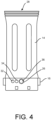
- the end cap 16 is rotatable in relation to the container 14. As shown particularly in Fig. 4 , for instance, the end cap includes at least one dispensing orifice. In Fig. 4 , for instance, the end cap defines three orifices 32, 34 and 36. The surface area or diameter of each orifice varies. For instance, orifice 32 has a smaller surface area than orifice 34, which has a smaller surface area than orifice 36. Orifice 36, for instance, can generally have the same diameter or surface area as the aperture 26.
- Each orifice can generally have a diameter of from about 2mm to about 25 mm.
- each orifice can have a diameter of greater than about 3 mm, such as greater than about 4 mm, such as greater than about 5 mm, such as greater than about 6 mm, such as greater than about 7 mm, such as greater than about 8 mm.
- the diameter of each orifice can generally be less than about 20 mm, such as less than about 15 mm, such as less than about 13 mm, such as less than about 12 mm, such as less than about 11 mm, such as less than about 10 mm.
- the end cap 16 includes a closed position in which the orifice 26 is completely blocked. In the closed position, the chemical composition contained within the floating chemical dispenser 10 remains protected and is not released from the container. Rotating the end cap 16 so that one of the orifices 32, 34 or 36 aligns with the aperture 26, however, places the floating chemical dispenser 10 into a chemical dispensing position where water can enter the container 14 for releasing the chemical composition.
- the orifices 32, 34 and 36 have different sizes for controlling the amount of chemical that is released. Having different orifices as shown in Fig. 4 allows for the floating chemical dispenser 10 to be adjustable. For instance, a particular orifice size may be selected based upon the size of the body of water or the pool size.
- a larger orifice may be selected.
- the different orifices can also be used to treat the pool in different ways.
- the large orifice 36 may be aligned with the aperture 26 in order to shock the pool and release large amounts of chemical very quickly.
- the smaller orifice 32 on the other hand, can be selected for a continuous release of the chemical and to maintain the pool within the proper chemical balance.
- Orifice 34 on the other hand, can be selected in order to make slight adjustments in order to, for instance, prevent the growth of algae.
- the floating chemical dispenser 10 in accordance with the present disclosure further includes a locking device that prevents the end cap 16 from rotating when the locking device is enabled.
- the locking device of the present disclosure can be engaged and disengaged repeatedly. In this manner, the end cap 16 can be locked in to a closed position even after the floating chemical dispenser 10 has been removed from the packaging in which it is shipped and sold.
- the locking device can be engaged after the floating chemical dispenser 10 has been partially used. For instance, in some situations, a user may want to remove the floating chemical dispenser from a pool for short periods of time or in order to store the dispenser during the off season or during a pool party.
- the locking device of the present disclosure can also be designed to be child resistant to prevent a child from inadvertently rotating the end cap 16.
- Figs. 4 through 8 illustrate one embodiment of a locking device in accordance with present disclosure.
- the end cap 16 includes a pair of opposing tab portions 40.
- the tab portions can be positioned 180° apart along the end cap 16. In other embodiments, the tab portions 30 can be spaced from about 90° to about 180° apart.
- Each tab portion 40 includes a locking tab 42 as particularly shown in Figs. 8 , 9 and 10 .
- the locking tab 42 engages the container 14 and prevents the end cap 16 from rotating.
- the container 14 can define a recess 44 as shown in Figs. 6 , 9 and 10 . When the locking tab 42 is contained within the recess 44, the locking tab 42 prevents the end cap 16 from rotating.
- a user can simultaneously press the tab portions 40 and twist the end cap 16. For instance, as particularly shown in Fig. 10 , when the tab portion 40 is pressed inwardly, the locking tab 42 pivots out of the recess 44 and allows the end cap 16 to rotate.
- the locking device on the floating chemical dispenser 10 can be child resistant.
- having two tab portions 40 located on opposing sides of the container prevents a person with small hands from pressing in both tab portions simultaneously.
- the floating chemical dispenser 10 can include a retaining device.
- the container 14 can define a retaining ring 46.
- the end cap 16 defines a corresponding locking element 48 that resides within the retaining ring 46.
- the locking element 48 rotates within the retaining ring 46. In this manner, the retaining ring and the locking element maintain the end cap 16 in alignment on the container 14 and prevent the end cap from being removed from the container.
- the container 14 defines recesses 44 and the retaining ring 46, while the end cap defines locking tabs 42 and locking elements 48. It should be understood, however, that these structures can be reversed. For instance, the recesses and the retaining ring can be located on the end cap, while the locking tabs and the locking element can be located on the container 14.
- the container 14 can also include an abutment 50.
- the abutment 50 can be designed to prevent the end cap 16 from rotating in a particular direction.
- the abutment 50 can be positioned to allow the end cap 15 to rotate in a direction so that the orifices 32, 34 and 36 become aligned with the aperture 26 and prevent the end cap 16 from rotating in an opposite direction.
- the floating chemical dispenser 10 can include a system that allows the user to know the closed position and the different chemical dispensing positions have been obtained when the end cap 16 is rotated.
- the end cap 16 is shown in relation to a bottom surface 52 of the container 14.
- Fig. 11 illustrates the surface of the end cap 16 that resides adjacent to the bottom surface 52 as shown in Fig. 12 .
- the end cap 16 defines a rib member 53 that projects from the surface of the end cap 16.
- the bottom surface 52 of the container 14 defines rib receiving channels 54, 56, 58 and 60.
- the rib receiving channels are located on a path of travel of the rib member when the end cap 16 is rotated.
- Each rib receiving channel 54, 56, 58 and 60 corresponds to a different position of the end cap 16 on the container 14.
- rib receiving channel 54 corresponds to the closed position of the floating chemical dispenser 10.
- Rib receiving channel 56 corresponds to a first chemical dispensing position
- rib receiving channel 58 corresponds to a second chemical dispensing position
- rib receiving channel 60 corresponds to a third chemical dispensing position of the floating chemical dispenser.
- the large orifice 36 becomes aligned with the aperture 26 on the container 14.
- the bottom surface 52 of the container 14 can also include abutments 60.
- the abutments 60 are designed to engage the rib member 53 and prevent the end cap 16 from rotating in a direction opposite to the rib receiving channels 54.
- the end cap 16 includes a single tab portion 70.
- the tab portion 70 includes a locking tab that engages the bottom of the container 14 and prevents the end cap 16 from rotating.
- the tab portion 70 can include a locking tab that resides in a recess within the container 14.
- the tab portion 70 is raised. While the tab portion 70 is raised, the end cap 16 can be rotated to any desired position.
- the tab portion 70 engages the bottom of the container 14.
- the locking tabs 42 engaged the side of the container 14.
- Fig. 15 illustrates another embodiment of a locking device in accordance with the present disclosure.
- the end cap 16 includes one or more removable locking tabs 72.
- the locking tab 72 can reside within a channel or recess 74 defined by the container 14 which prevents the end cap 16 from rotating.
- the locking tab 72 is removable. For instance, the locking tab 72 can be torn away from the end cap 16 which allows the end cap 16 to rotate.
- the end cap 16 includes one or more pull tabs 80.
- the pull tabs 80 include a locking tab that engages the container and prevents the end cap 16 from rotating. In order to disable the locking device, the pull tabs 80 are pulled away from the body of the container, which allows the end cap 16 to rotate.
- Fig. 17 illustrates yet another embodiment of a locking device in accordance with the present disclosure.
- the container 14 defines a pin 82 that resides within a slot 84 defined by the end cap 16.
- the slot 84 has a non-linear travel path.
- the slot includes a first vertical section followed by a first horizontal section followed by a second vertical section followed by a second horizontal section.
- the end cap is twisted and manipulated so that the pin 82 follows the slot 84.
- the end cap 16 in order to rotate the end cap 16 to the different chemical dispensing positions, the end cap is pulled downwardly and/or pushed upwardly while being rotated in order for the pin to follow the travel path of the slot 84.
- the travel path of the slot 84 can include various stopping points where horizontal portions intersect with vertical portions. These stopping points can correspond to different positions on the floating chemical dispenser 10. Each stopping point, for instance, may define a closed position or a chemical dispensing position.
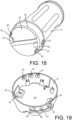
- FIG. 18 and 19 still another embodiment of a locking device in accordance with the present disclosure is shown. Like reference numerals have been used to indicate similar elements.
- the locking device illustrated in Figs. 18 and 19 is somewhat similar to the locking device illustrated in Figs. 4 through 10 .
- the end cap 16 engages the bottom 30 of the container 14 instead of the side of the container.
- the end cap 16 includes opposing tab portions 40 similar to the embodiment illustrated in Figs 4 through 10 . Located on each tab portion 40 is a locking tab 42. Locking tab 42 is located on the bottom surface of the end cap 16 facing the container 14.
- the container 14 includes a pair of opposing locking tab channels 90.
- the locking tab channels 90 are for receiving the corresponding pair of locking tabs 42 when the end cap 16 is in the locked position.
- the bottom 30 of the container 14 further defines a pair of opposing tab engaging members 92.
- the tab engaging members 92 prevent the locking tabs 42 from rotating when the end cap 16 is twisted.
- each of the tab portions 40 can be pressed inwardly simultaneously. When the tab portions 40 are pushed inwardly, the locking tabs 42 move radially within each locking tab channel 90 until locking tab 42 clears each corresponding tab engaging member 92. Consequently, pressing the tab portions 40 simultaneously allows the end cap 16 to rotate so that one of the orifices 32, 34, and 36 can align with the one or more apertures 26 on the container 14.
- the bottom 30 of the container 14 can further include two opposing abutments 60.
- the abutments 60 engage the locking tabs 42 and prevent the end cap 16 from rotating in one direction.
- the abutments 60 prevent the end cap from rotating counterclockwise.
- the abutments 60 have a greater length than the tab engaging members 92. In this manner, the end cap 16 is prevented from rotating in one direction even when the tab portions 40 are pressed inwardly.
- the end cap 16 includes two different sets of orifices.
- the container 14 can include two different apertures 26 for engaging the orifices 32, 34 and 36.
- the end cap 16 can include a shield member 94 that protects the orifices 32, 34 and 36 from being contacted with a person's hand. The shield member 94, for instance, can prevent any lose chemical from contact with the user when the end cap 16 is rotated.
- the locking device illustrated in Figs. 18 and 19 may offer various advantages and benefits. For instance, by placing the locking tabs on the bottom surface of the end cap, the top of the end cap 16 can remain a solid structure for improved structural integrity.
Landscapes
- Engineering & Computer Science (AREA)
- Chemical & Material Sciences (AREA)
- Water Supply & Treatment (AREA)
- Environmental & Geological Engineering (AREA)
- Hydrology & Water Resources (AREA)
- Life Sciences & Earth Sciences (AREA)
- Organic Chemistry (AREA)
- Architecture (AREA)
- Chemical Kinetics & Catalysis (AREA)
- Health & Medical Sciences (AREA)
- Medicinal Chemistry (AREA)
- Civil Engineering (AREA)
- Structural Engineering (AREA)
- Closures For Containers (AREA)
- Containers And Packaging Bodies Having A Special Means To Remove Contents (AREA)
Description
- The present application is based on and claims priority to
U.S. Provisional Patent application Serial No. 62/504,593, filed on May 11, 2017 - Swimming pool water, fountain water, and the like are susceptible to infestation by various microorganisms, such as algae. For instance, if untreated, swimming pool water can provide a hospitable forum for the growth of bacteria, algae and other undesirable and potentially unhealthy organisms. Consequently, pool water, and spas are typically treated with chemicals designed to kill and control the above organisms. The chemicals can be applied to the pool water on a periodic or a continuous basis.
- Such treatment, for instance, is typically undertaken via the introduction of a halogen, such as chlorine, into the pool water at levels effective to kill or control the unwanted organisms. The halogen source may be in liquid form or may be in a solid form. The solid form can be designed to quickly or slowly dissolve in the pool water. Solid sources of chlorine, for instance, include calcium hypochlorite and the like.
- Various different techniques and methods have been developed in order to deliver a chemical, such as chlorine, to pool water. For instance, one type of chemical feeder that has been used in the past is referred to as a flowing erosion dispenser that provides continuous release of the chemical. The floating chemical dispenser, for instance, can include an upper end float attached to a container. A solid chemical can be placed in the container and the container can include at least one opening that allows water to enter the container and dissolve the chemical for release into the pool water. In one embodiment, the floating dispenser, when empty, has a center of gravity that is not symmetrical with the container. Consequently, as the chemical within the container is dissolved and becomes exhausted, the floating dispenser tips over and floats horizontally in the water indicating to a user that the floating dispenser is empty and needs to be replaced.
- One embodiment of a floating chemical dispenser is disclosed in
U.S. Patent No. 7,704,467 . In the '467 patent, the floating dispenser contains chemical tablets composed of compressed calcium hypochlorite, an algicide, and an agglomerating agent, such as zinc sulfate and sodium Further relevant documents areUS 2013/092634 A1 andUS 2004/175311 A1 . - Floating chemical dispensers typically include a closing mechanism that closes the opening in the container to prevent inadvertent release of the chemical contained in the dispenser. The closing mechanism, however, can be susceptible to opening during packing, shipping and handling of the dispenser. Consequently, in the past, a shrink wrap film or tape was placed over the closing mechanism to keep the dispenser in a closed position until the dispenser was placed in use. Shrink wrap film or tape as described above, however, cannot be reused, and, once removed from the dispensing container, leaves the closure mechanism unprotected.
- In view of the above, a need exists for a locking device capable of maintain a floating chemical dispenser in the closed position to prevent against inadvertent spills or release of the chemical contained in the dispenser. A need further exists for a locking mechanism for floating pool dispensers that are also child resistant.
- In general, the present disclosure is directed to a floating chemical dispenser for containing and dispensing chemicals into a body of water, such as into pool water or water contained in a spa. The floating chemical dispenser can also be used in all different types of water systems, such as public fountains and the like. In accordance with the present disclosure, the floating chemical dispenser includes a locking device that prevents the dispenser from inadvertent spills or opening of the container prior to use. In one embodiment, the locking device can include child resistant characteristics and properties.
- The present invention is directed to a floating chemical dispenser for containing and dispensing chemicals to treat a body of water. The dispenser includes a float positioned at an upper end of the dispenser. The floating chemical dispenser further includes a container having a top and a bottom. The top of the container is adjacent to the float. For instance, in one embodiment, the top of the container can be attached to the float or, alternatively, a collar can be used to attach the float to the container. The container defines an interior compartment configured to hold a chemical. The chemical, for instance, may comprise a solid chemical. The solid chemical may comprise a halogen source, such as a chlorine source that releases chlorine when dissolved. In one embodiment, for instance, the chemical contained in the container may comprise trichloro-s-triazinetrione. The container can include an open top for receiving the chemical and a closed bottom. The container also defines at least one aperture positioned to receive water from the outside environment for combining with a chemical and dispensing the chemical into the body of water.
- The floating chemical dispenser further includes an end cap attached to the bottom of the container. The end cap can be held on the container by a retaining device. The retaining device can be designed to prevent the end cap from being released from the container. In one embodiment, for instance, the retaining device comprises a retaining ring on the container and a locking element on the end cap. The locking element can reside within the retaining ring on the container. The end cap defines at least one orifice and is rotatable in relation to the retainer. The end cap is rotatable between a closed position and a chemical dispensing position. When in the chemical dispensing position, the at least one orifice is aligned with the aperture on the container. In one embodiment, the end cap can include two orifices, three orifices, or more. Each orifice can have a different surface area. In this manner, a particular orifice can be aligned with the aperture for controlling the amount of chemical that is released from the dispenser.
- In accordance with the present invention, the floating chemical dispenser further includes a locking device that prevents the end cap from rotating when enabled.
- In one embodiment, the end cap includes two opposing tab portions that, when pressed simultaneously, disables the locking device and allows the end cap to rotate. For example, in one embodiment, the locking device may comprise at least one locking tab located on the end cap. Pressing both of the tab portions simultaneously causes the locking tabs to move from a locked position to an unlocked position so that the end cap can rotate. In one embodiment, for instance, each locking tab can reside in a recess located on a container which prevents the cap from rotating. Pressing both tab portions simultaneously, however, moves the locking tabs out of the recesses and disables the locking device. The locking tabs and the recesses can be located at any suitable location on the end cap and on the container. In one embodiment, for example, the recesses are located on a side wall of the container.
- In an alternative embodiment, the locking device includes a tab portion that engages the container and prevents the end cap from rotating. In this embodiment, lifting the tab portion causes the tab portion to disengage the container and disable the locking device.
- In another embodiment, the locking device includes at least one removable tab that engages the container and prevents the end cap from rotating. The tab may be located on the end cap and may have a perimeter defined by perforations that lets the tab be removed from the container for disabling the locking device.
- In one embodiment, the locking tab on the end cap can include a pull tab. Pulling the tab disengages the locking device and allows the end cap to rotate.
- In yet another embodiment, the locking device comprises a pin on the container that resides in a slot located on the end cap. The slot can include a first vertical portion, a horizontal portion, and a second vertical portion. Moving the end cap so that the pin travels over the slot causes the end cap to rotate and disables a locking device. The floating chemical dispenser of the present disclosure can also include various other features. In one embodiment, the end cap includes a rib member and the container defines a plurality of rib receiving channels. The rib receiving channels are located along a path of travel of the rib member when the cap is rotated. Each rib receiving channel can be positioned so as to align with a position on the end cap. For instance, one of the rib receiving channels can align with the rib member at a closed position of the end cap. Another rib receiving channel can align with the rib member when the end cap is rotated to a chemical dispensing position. The rib member and rib receiving channels not only allow the user to determine how much to rotate the end cap but also temporarily holds the end cap at a desired position. In one embodiment, the rib receiving channels can be located on the bottom surface of the container and the rib member can be located on an adjoining surface of the end cap. The bottom surface of the container can also include an abutment that prevents the end cap from rotating in one direction. In this manner, the end cap only rotates in a direction toward the chemical dispensing position.
- Other features and aspects of the present disclosure are discussed in greater detail below.
- A full and enabling disclosure of the present disclosure is set forth more particularly in the remainder of the specification, including reference to the accompanying figures, in which:
-
Fig. 1 illustrates one embodiment of a floating chemical dispenser made in accordance with the present disclosure; -
Fig. 2 illustrates another embodiment of a floating chemical dispenser made in accordance with the present disclosure including a retaining collar; -
Fig. 3 is a perspective view of the retaining collar incorporated into the floating chemical dispenser illustrated inFig. 2 ; -
Fig. 4 illustrates one embodiment of a container and an end cap that may be used to construct a floating chemical dispenser in accordance with the present disclosure; -
Fig. 5 is another view of the container and the end cap ofFig. 4 ; -
Fig. 6 illustrates one embodiment of a container that may be incorporated into a floating chemical dispenser in accordance with the present disclosure; -
Fig. 7 illustrates a side view of one embodiment of an end cap for a floating chemical dispenser in accordance with the present disclosure; -
Fig. 8 illustrates a cross sectional view of the end cap illustrated inFig. 7 ; -
Fig. 9 illustrates a cross sectional view of the end cap illustrated inFig. 8 when engaged with the container illustrated inFig. 6 ; -
Fig. 10 illustrates an enlarged portion of the end cap and the container illustrated inFig. 9 ; -
Fig. 11 illustrates a plan view of one embodiment of an end cap in accordance with the present disclosure, -
Fig. 12 illustrates a bottom view of a container made in accordance with the present disclosure that may be incorporated into a floating chemical dispenser; -
Fig. 13 illustrates one embodiment of an end cap engaged with a portion of a container that may be used to construct a floating chemical dispenser in accordance with the present disclosure; -
Fig. 14 illustrates another embodiment of a locking device that may be incorporated into an end cap in accordance with the present disclosure; -
Fig. 15 illustrates another embodiment of a locking device that may be incorporated into an end cap in accordance with the present disclosure; -
Fig. 16 illustrates another embodiment of a locking device that may be incorporated into an end cap in accordance with the present disclosure; -
Fig. 17 illustrates another embodiment of a locking device that may be incorporated into an end cap in accordance with the present disclosure; -
Fig. 18 illustrates yet another embodiment of a locking device that may be incorporated into the floating chemical dispenser illustrating the container portion of the locking device; and -
Fig. 19 illustrates an end cap that may be used in conjunction with the container illustrated inFig. 18 . - Repeat use of reference characters in the present specification and drawings is intended to represent the same or analogous features or elements of the present invention.
- It is to be understood by one of ordinary skill in the art that the present discussion is a description of exemplary embodiments only, and is not intended as limiting the broader aspects of the present disclosure.
- In general, the present invention is directed to a floating chemical dispenser. The floating chemical dispenser includes a float and a container for a chemical. When a chemical is loaded into the container and the dispenser is dropped into a body of water, the floating chemical dispenser floats upright and slowly releases the chemical contained within the container. The container includes an aperture that allows water to enter the container and dissolve the chemical. In accordance with the present invention, the container further includes an end cap that rotates on the container between a closed position that blocks the aperture and a chemical dispensing position in which an orifice on the end cap aligns with the aperture on the container to allow water to enter the container. The end cap and the container further include a locking device that prevents the end cap from rotating. The locking device can be used to prevent against inadvertent chemical spills or release. The locking device on the end cap can also be designed to be child resistant.
- In one embodiment, the locking device can be designed for repeated use. For example, in one embodiment, the locking device includes a locking tab or element located on the container or on the end cap. The end cap can include two opposing tab portions that, when pressed simultaneously, release the locking element or tab and allow the end cap to be rotated.
- Referring to
Fig. 1 , one embodiment of a floatingchemical dispenser 10 made in accordance with the present disclosure is shown. As illustrated, the floatingchemical dispenser 10 includes afloat 12 attached to acontainer 14. Thecontainer 14 is for holding a chemical. Attached to the container is anend cap 16. The end cap rotates between a closed position that prevents the chemical from be dispensed and one or more chemical dispensing positions that allow water from the environment to enter the container and dissolve the chemical. - Referring to
Fig. 2 , another embodiment of a floating chemical dispenser is illustrated. Like reference numerals have been used to indicate similar elements. As shown, in the embodiment illustrated inFig. 2 , the floatingchemical dispenser 10 includes afloat 12 and anend cap 16. In addition, the floatingchemical dispenser 10 includes a retainingcollar 18. The retainingcollar 18 connects thefloat 12 to thecontainer 14. - Referring to
Fig. 3 , the retainingcollar 18 is shown in more detail. As illustrated, the retainingcollar 18 includes a first plurality ofthreads 20 that are intended to engage thefloat 12. On the opposite side, the retaining collar further includes a second set ofthreads 22 that attach to and engage thecontainer 14. As shown inFig. 3 , the retainingcollar 18 can further include a plurality ofvent openings 24. Thevent openings 24 can allow gases within thecontainer 14 to be released and water to flow back into the body. - The
container 14 of the floatingchemical dispenser 10 includes an interior compartment that is designed to hold a chemical. The chemical, for instance, may comprise a solid that dissolves and releases a sanitizing agent capable of killing or controlling unwanted organisms such as bacteria, algae and the like in a body of water. For example, the chemical may comprise a halogen source, such as a chlorine source. Solid sources of chlorine include calcium hypochlorite, dichloroisocyanuric acid, trichloroisocyanuric acid and the like. In one embodiment, the chlorine source comprises trichloro-s-triazinetrione. The halogen source may be present alone or in conjunction with other components within the solid composition. The halogen source may be combined with various other compatible chemicals for different purposes and benefits. For instance, the solid chemical may also contain other biocides or algicides, agglomerating agents and the like. In one embodiment, the solid may contain zinc sulfate, zinc oxide, and/or sodium aluminate. The solid chemical composition can be present in the container in any suitable form. For instance, the solid chemical may be in the form of pellets, granules or the like. In one embodiment, for instance, thecontainer 14 includes disks made from the solid chemical composition. Alternatively, the container may include loose chemicals or chemicals held with an inner package or with a shrink film. The inner package shall secure the chemical contents, but allow water to flow freely to allow the chemicals to dissolve. The inner package can be mesh, water soluble film, shrink sleeve film with holes, etc. Thecontainer 14 can have any length in order to accommodate one disk or a plurality of disks. For example, in one embodiment, thecontainer 14 may be designed to hold three disks stacked together within the interior compartment. - Referring to
Figs. 4 through 10 , thecontainer 14 and theend cap 16 are shown in greater detail. As shown inFig. 6 , thecontainer 14 can include an open top 28 and aclosed bottom 30. As shown inFig. 4 , the container can also define anaperture 26. Theaperture 26 allows water from the surrounding environment to enter the interior compartment of thecontainer 14 and dissolve the chemical composition held within the container. As the chemical composition dissolves, a chemical is released into the surrounding water for controlling algae, bacteria, and other microorganisms. In this manner, the floatingchemical dispenser 10 can be placed in a body of water, such as in pool water, and can float and dispense chemical continuously. The size of theaperture 26 can be controlled in order to control the amount of chemical that is dispensed. - According to the invention, the floating
chemical dispenser 10 is designed to indicate to a user when the chemical composition has fully dissolved and has been exhausted. For instance, thechemical dispenser 10 is designed to float upright when containing a chemical composition. When the chemical composition has completely dissolved, the floatingchemical dispenser 10 has a center of gravity slightly off center that causes the dispenser to tip over and float in a more horizontal position. Various different methods and techniques can be implemented in order to give the floating chemical dispenser 10 a center of gravity that is slightly off center (from a central axis that extends from the top to the bottom of the dispenser). For instance, inU.S. Patent No. 7,704,467 , a disk can be placed in thecontainer 14 and positioned off center which can cause the floatingchemical dispenser 10 to tip over if empty and placed in a body of water. In alternative embodiments, extra weight can be placed off center in thecontainer 14, in thefloat 12, in theend cap 16, or in the retainingcollar 18. - The
end cap 16 is rotatable in relation to thecontainer 14. As shown particularly inFig. 4 , for instance, the end cap includes at least one dispensing orifice. InFig. 4 , for instance, the end cap defines threeorifices orifice 32 has a smaller surface area thanorifice 34, which has a smaller surface area thanorifice 36.Orifice 36, for instance, can generally have the same diameter or surface area as theaperture 26. - Each orifice can generally have a diameter of from about 2mm to about 25 mm. For instance, each orifice can have a diameter of greater than about 3 mm, such as greater than about 4 mm, such as greater than about 5 mm, such as greater than about 6 mm, such as greater than about 7 mm, such as greater than about 8 mm. The diameter of each orifice can generally be less than about 20 mm, such as less than about 15 mm, such as less than about 13 mm, such as less than about 12 mm, such as less than about 11 mm, such as less than about 10 mm.
- The
end cap 16 includes a closed position in which theorifice 26 is completely blocked. In the closed position, the chemical composition contained within the floatingchemical dispenser 10 remains protected and is not released from the container. Rotating theend cap 16 so that one of theorifices aperture 26, however, places the floatingchemical dispenser 10 into a chemical dispensing position where water can enter thecontainer 14 for releasing the chemical composition. Theorifices Fig. 4 allows for the floatingchemical dispenser 10 to be adjustable. For instance, a particular orifice size may be selected based upon the size of the body of water or the pool size. For larger pools, for instance, a larger orifice may be selected. The different orifices can also be used to treat the pool in different ways. For instance, thelarge orifice 36 may be aligned with theaperture 26 in order to shock the pool and release large amounts of chemical very quickly. Thesmaller orifice 32, on the other hand, can be selected for a continuous release of the chemical and to maintain the pool within the proper chemical balance.Orifice 34, on the other hand, can be selected in order to make slight adjustments in order to, for instance, prevent the growth of algae. - In order to avoid inadvertent release or spills of the chemical composition, the floating
chemical dispenser 10 in accordance with the present disclosure further includes a locking device that prevents theend cap 16 from rotating when the locking device is enabled. In one embodiment, the locking device of the present disclosure can be engaged and disengaged repeatedly. In this manner, theend cap 16 can be locked in to a closed position even after the floatingchemical dispenser 10 has been removed from the packaging in which it is shipped and sold. In addition, the locking device can be engaged after the floatingchemical dispenser 10 has been partially used. For instance, in some situations, a user may want to remove the floating chemical dispenser from a pool for short periods of time or in order to store the dispenser during the off season or during a pool party. The locking device of the present disclosure can also be designed to be child resistant to prevent a child from inadvertently rotating theend cap 16. -
Figs. 4 through 8 illustrate one embodiment of a locking device in accordance with present disclosure. As shown inFigs. 5 and7 , for instance, theend cap 16 includes a pair of opposingtab portions 40. In one embodiment as shown inFig. 8 , the tab portions can be positioned 180° apart along theend cap 16. In other embodiments, thetab portions 30 can be spaced from about 90° to about 180° apart. Eachtab portion 40 includes alocking tab 42 as particularly shown inFigs. 8 ,9 and 10 . Thelocking tab 42 engages thecontainer 14 and prevents theend cap 16 from rotating. For instance, thecontainer 14 can define arecess 44 as shown inFigs. 6 ,9 and 10 . When thelocking tab 42 is contained within therecess 44, thelocking tab 42 prevents theend cap 16 from rotating. - In order to disable the locking device and rotate the
end cap 16, a user can simultaneously press thetab portions 40 and twist theend cap 16. For instance, as particularly shown inFig. 10 , when thetab portion 40 is pressed inwardly, thelocking tab 42 pivots out of therecess 44 and allows theend cap 16 to rotate. - As described above, the locking device on the floating
chemical dispenser 10 can be child resistant. In this regard, having twotab portions 40 located on opposing sides of the container prevents a person with small hands from pressing in both tab portions simultaneously. - In order to keep the
end cap 16 on thecontainer 14 and to make sure that theend cap 16 rotates in alignment with the container, the floatingchemical dispenser 10 can include a retaining device. As shown inFigs. 6 ,9 and 10 , for instance, thecontainer 14 can define a retainingring 46. Theend cap 16, on the other hand, defines acorresponding locking element 48 that resides within the retainingring 46. When theend cap 16 is rotated, the lockingelement 48 rotates within the retainingring 46. In this manner, the retaining ring and the locking element maintain theend cap 16 in alignment on thecontainer 14 and prevent the end cap from being removed from the container. - In
Figs. 6 thrugh10, thecontainer 14 definesrecesses 44 and the retainingring 46, while the end cap defines lockingtabs 42 and lockingelements 48. It should be understood, however, that these structures can be reversed. For instance, the recesses and the retaining ring can be located on the end cap, while the locking tabs and the locking element can be located on thecontainer 14. - Referring to
Fig. 6 , thecontainer 14 can also include anabutment 50. Theabutment 50 can be designed to prevent theend cap 16 from rotating in a particular direction. For instance, theabutment 50 can be positioned to allow the end cap 15 to rotate in a direction so that theorifices aperture 26 and prevent theend cap 16 from rotating in an opposite direction. - In one embodiment, the floating
chemical dispenser 10 can include a system that allows the user to know the closed position and the different chemical dispensing positions have been obtained when theend cap 16 is rotated. For instance, referring toFigs. 11 through 13 , theend cap 16 is shown in relation to abottom surface 52 of thecontainer 14.Fig. 11 illustrates the surface of theend cap 16 that resides adjacent to thebottom surface 52 as shown inFig. 12 . As shown inFig. 11 , theend cap 16 defines arib member 53 that projects from the surface of theend cap 16. Referring toFig. 12 , thebottom surface 52 of thecontainer 14, on the other hand, definesrib receiving channels end cap 16 is rotated. Eachrib receiving channel end cap 16 on thecontainer 14. For instance,rib receiving channel 54 corresponds to the closed position of the floatingchemical dispenser 10.Rib receiving channel 56 corresponds to a first chemical dispensing position,rib receiving channel 58 corresponds to a second chemical dispensing position, andrib receiving channel 60 corresponds to a third chemical dispensing position of the floating chemical dispenser. As shown inFig. 13 , for instance, when theend cap 16 is rotated such that therib member 53 resides in therib receiving channel 60, thelarge orifice 36 becomes aligned with theaperture 26 on thecontainer 14. Similarly, when theend cap 16 is rotated such that therib member 53 is contained within therib receiving channel 58, themiddle orifice 36 is aligned with theaperture 26. When theend cap 16 is rotated such that therib member 53 resides in therib receiving channel 56, on the other hand, thesmallest orifice 32 is aligned with theaperture 26. When theend cap 16 is rotated as described above, a user will feel a sensation as therib member 53 slides across thebottom surface 52 of thecontainer 14 and enters and leaves each of therib receiving channels end cap 16 is rotated. - As shown in
Figs. 12 and13 , thebottom surface 52 of thecontainer 14 can also includeabutments 60. Theabutments 60 are designed to engage therib member 53 and prevent theend cap 16 from rotating in a direction opposite to therib receiving channels 54. - In the embodiment illustrated in
Figs. 4 through 10 , one embodiment of a locking device is shown and illustrated. Referring now toFigs. 14 through 17 , other embodiments of locking devices that may be used in accordance with the present disclosure are shown. Like reference numerals have been used to indicate similar elements. Referring toFig. 14 , for instance theend cap 16 includes asingle tab portion 70. Thetab portion 70 includes a locking tab that engages the bottom of thecontainer 14 and prevents theend cap 16 from rotating. For instance, thetab portion 70 can include a locking tab that resides in a recess within thecontainer 14. In order to rotate theend cap 16, thetab portion 70 is raised. While thetab portion 70 is raised, theend cap 16 can be rotated to any desired position. In the embodiment illustrated inFig. 14 , thetab portion 70 engages the bottom of thecontainer 14. In the embodiment illustrated inFigs. 4 through 10 , on the other hand, the lockingtabs 42 engaged the side of thecontainer 14. -
Fig. 15 illustrates another embodiment of a locking device in accordance with the present disclosure. InFig. 15 , theend cap 16 includes one or moreremovable locking tabs 72. As shown inFig. 15 , thelocking tab 72 can reside within a channel orrecess 74 defined by thecontainer 14 which prevents theend cap 16 from rotating. In order to disable the locking device, thelocking tab 72 is removable. For instance, thelocking tab 72 can be torn away from theend cap 16 which allows theend cap 16 to rotate. - Still another embodiment of a locking device in accordance with the present disclosure is shown in
Fig. 16 . InFig. 16 , theend cap 16 includes one ormore pull tabs 80. Thepull tabs 80 include a locking tab that engages the container and prevents theend cap 16 from rotating. In order to disable the locking device, thepull tabs 80 are pulled away from the body of the container, which allows theend cap 16 to rotate. -
Fig. 17 illustrates yet another embodiment of a locking device in accordance with the present disclosure. InFig. 17 , thecontainer 14 defines apin 82 that resides within aslot 84 defined by theend cap 16. Theslot 84 has a non-linear travel path. In the embodiment illustrated inFig. 17 , for instance, the slot includes a first vertical section followed by a first horizontal section followed by a second vertical section followed by a second horizontal section. In order to rotate theend cap 16, the end cap is twisted and manipulated so that thepin 82 follows theslot 84. Thus, in order to rotate theend cap 16 to the different chemical dispensing positions, the end cap is pulled downwardly and/or pushed upwardly while being rotated in order for the pin to follow the travel path of theslot 84. As shown inFig. 17 , the travel path of theslot 84 can include various stopping points where horizontal portions intersect with vertical portions. These stopping points can correspond to different positions on the floatingchemical dispenser 10. Each stopping point, for instance, may define a closed position or a chemical dispensing position. - Referring to
Figs. 18 and 19 , still another embodiment of a locking device in accordance with the present disclosure is shown. Like reference numerals have been used to indicate similar elements. In general, the locking device illustrated inFigs. 18 and 19 is somewhat similar to the locking device illustrated inFigs. 4 through 10 . In the embodiment illustrated inFigs. 18 and 19 , however, theend cap 16 engages the bottom 30 of thecontainer 14 instead of the side of the container. - Referring to
Fig. 19 , theend cap 16 includes opposingtab portions 40 similar to the embodiment illustrated inFigs 4 through 10 . Located on eachtab portion 40 is alocking tab 42. Lockingtab 42 is located on the bottom surface of theend cap 16 facing thecontainer 14. - Referring to
Fig. 18 , thecontainer 14 includes a pair of opposinglocking tab channels 90. Thelocking tab channels 90 are for receiving the corresponding pair of lockingtabs 42 when theend cap 16 is in the locked position. The bottom 30 of thecontainer 14 further defines a pair of opposingtab engaging members 92. Thetab engaging members 92 prevent thelocking tabs 42 from rotating when theend cap 16 is twisted. In order to disable the locking device, each of thetab portions 40 can be pressed inwardly simultaneously. When thetab portions 40 are pushed inwardly, the lockingtabs 42 move radially within eachlocking tab channel 90 until lockingtab 42 clears each correspondingtab engaging member 92. Consequently, pressing thetab portions 40 simultaneously allows theend cap 16 to rotate so that one of theorifices more apertures 26 on thecontainer 14. - As shown in
Fig. 18 , the bottom 30 of thecontainer 14 can further include two opposingabutments 60. Theabutments 60 engage the lockingtabs 42 and prevent theend cap 16 from rotating in one direction. In the embodiment illustrated inFig. 18 , for instance, theabutments 60 prevent the end cap from rotating counterclockwise. As shown, theabutments 60 have a greater length than thetab engaging members 92. In this manner, theend cap 16 is prevented from rotating in one direction even when thetab portions 40 are pressed inwardly. - As shown in
Fig. 19 , theend cap 16 includes two different sets of orifices. Likewise, thecontainer 14 can include twodifferent apertures 26 for engaging theorifices Fig. 19 , theend cap 16 can include ashield member 94 that protects theorifices shield member 94, for instance, can prevent any lose chemical from contact with the user when theend cap 16 is rotated. - The locking device illustrated in
Figs. 18 and 19 may offer various advantages and benefits. For instance, by placing the locking tabs on the bottom surface of the end cap, the top of theend cap 16 can remain a solid structure for improved structural integrity.
Claims (15)
- A floating chemical dispenser (10) for containing and dispensing chemicals to treat a body of water, the dispenser comprising;a float (12) positioned at an upper end of the dispenser;a container (14) having a top and a bottom, the top of the container (14) being adjacent to the float (12) and optionally connected thereto by a retaining collar (18), the container (14) defining in an interior compartment configured to hold a chemical, the container (14) defining at least one aperture (26) positioned to receive water from the outside environment for combining with a chemical and dispensing the chemical into a body of water;an end cap (16) attached to the bottom (30) of the container (14), the end cap being held on the container (14) by a retaining device, the end cap (16) defining at least one orifice (32, 34, 36) and being rotatable in relation to the container (14), the end cap (16) being rotatable between a closed position and a chemical dispensing position, wherein, when in the chemical dispensing position, the at least one orifice (32, 34, 36) is aligned with the aperture on the container;a locking device that prevents the end cap from rotating when enabled; and,extra weight placed off-center in the container (14), in the float (12), in the end cap (16) or, if present, in the retaining collar (18),wherein the extra weight provides the dispenser (10) with a center of gravity such that the chemical dispenser (10) floats upright when containing the chemical to treat the body of water, and to tip over and float in a horizontal position when the chemical has been fully dissolved or has been exhausted.
- The floating chemical dispenser (10) as defined in claim 1, wherein the end cap (16) includes two opposing tab portions (40) and wherein pressing both tab portions (40) simultaneously disables the locking device and allows the end cap (16) to rotate.
- The floating chemical dispenser (10) as defined in claim 2, wherein the locking device comprises a locking tab (42) located on the end cap (16) and wherein pressing both of the tab portions (40) simultaneously causes the locking tab (42) to move from a locked position to an unlocked position so that the end cap (16) can be rotated.
- The floating chemical dispenser (10) as defined in claim 3, wherein the locking tab (42) resides in a recess (44) located on the container which prevents the end cap (16) from rotating and wherein pressing both tab portions (40) simultaneously moves the locking tab (42) out of the recess (44) and disables the locking device.
- The floating chemical dispenser (10) as defined in claim 3, wherein the locking device includes two locking tabs (42), each locking tab (42) being located on one of the corresponding tab portions (40) and wherein pressing both of the tab portions (40) simultaneously causes the locking tabs (42) to move from a locked position to an unlocked position so that the end cap (16) can be rotated.
- The floating chemical dispenser (10) as defined in claim 5, wherein each locking tab (42) is located on a bottom surface of the end cap (16) facing the container (14), each locking tab (42) being configured to engage a bottom surface of the container (14) when the locking device is enabled to prevent the end cap (16) from rotating.
- The floating chemical dispenser (10) as defined in claim 6, wherein the bottom surface of the container defines a pair of opposing tab engaging members (92) that engage the corresponding locking tabs (42) on the end cap (16) and prevent the end cap (16) from rotating and wherein pressing both tab portions (40) simultaneously causes the locking tabs (42) to move out of engagement with the tab engaging members (92).
- The floating chemical dispenser (10) as defined in claim 1, wherein either:the locking device includes a tab portion (70) that engages the container (14) and prevents the end cap (16) from rotating and, wherein lifting the tab portion (70) causes the tab portion to disengage the container (14) and disable the locking device;the locking device includes at least one removal tab, the tab engaging the container for preventing the end cap (16) from rotating and wherein removing the tab from the end cap (16) disables the locking device;the locking device comprises a pull tab (80) located on the end cap and wherein pulling the pull tab (80) disables the locking device;the locking device comprises a pin (82) on the container contained within a slot (84) located on the end cap (16), the slot including a first vertical portion, a horizontal portion, and a second vertical portion, and wherein moving the end cap (16) so that the pin (82) travels over the slot (84) causes the end cap (16) to rotate and disables the locking device;the retaining device comprises a retaining ring (46) and a locking element, the retaining ring (46) being located on the container (14) and the locking element being located on the end cap (16), the locking element residing in the retaining ring;the container further includes an abutment that prevents the end cap (16) from rotating in one direction; or,the container (14) includes an open top end and closed bottom end.
- The floating chemical dispenser (10) as defined in claim 1, wherein the end cap (16) includes at least two orifices (32, 34, 36), the end cap (16) including a first orifice (36) that has a larger area than a second orifice (34) and wherein the end cap (16) rotates between a closed position, a first chemical dispensing position where the first orifice (36) aligns with the aperture (26) on the container (14) and a second chemical dispensing position where the second orifice (34) aligns with the aperture (26) on the container (14).
- The floating chemical dispenser (10) as defined in claim 9, wherein either:the end cap (16) includes a third orifice (32), the second orifice (34) having a larger area than the third orifice (32) and wherein the end cap (16) is rotatable to a third chemical dispensing position wherein the third orifice (32) aligns with the aperture (26) on the container (14); or,the end cap (16) further includes a rib member (53) and wherein the container (14) defines a plurality of rib receiving channels (54, 56, 58, 60), the rib receiving channels (54, 56, 58, 60) being located along a path of travel of the rib member (53) when the end cap (16) is rotated, and wherein a first rib receiving channel (56) is aligned with the first chemical dispensing position and a second rib receiving channel (58) is aligned with the second chemical dispensing position.
- The floating chemical dispenser (10) as defined in claim 1, wherein the end cap (16) includes a rib member (53) and wherein the container (14) defines a plurality of rib receiving channels (54, 56, 58, 60), the rib receiving channels (54, 56, 58, 60) being located along a path of travel of the rib member (53) when the end cap (16) is rotated, and wherein a first rib receiving channel (54) aligns with the rib member (53) at the closed position of the end cap (16) and wherein another receiving channel (56, 58, 60) aligns with the rib member (53) when the end cap (16) is rotated to the chemical dispensing position.
- The floating chemical dispenser (10) as defined in claim 11, wherein either:the container further defines an abutment (50) that prevents the rib member (53) from rotating in a direction opposite the chemical dispensing position; or,the rib member (53) is located on a bottom surface (52) of the end cap (16) and wherein the plurality of rib receiving channels (54, 56, 58, 60) are located on the bottom of the container (14).
- The floating chemical dispenser (10) as defined in claim 4, wherein the recess (44) is located on a side wall of the container (14).
- The floating chemical dispenser (10) as defined in claim 1, further comprising a sanitizing chemical contained within the container.
- The floating chemical dispenser (10) as defined in claim 14, wherein either:the sanitizing chemical comprises trichloro-s-triazinetrione; or,.the container (14) includes at least one other chemical in addition to the sanitizing chemical.
Applications Claiming Priority (2)
| Application Number | Priority Date | Filing Date | Title |
|---|---|---|---|
| US201762504593P | 2017-05-11 | 2017-05-11 | |
| PCT/US2018/031957 WO2018209019A1 (en) | 2017-05-11 | 2018-05-10 | Floating pool sanitizer with locking device |
Publications (3)
| Publication Number | Publication Date |
|---|---|
| EP3634873A1 EP3634873A1 (en) | 2020-04-15 |
| EP3634873A4 EP3634873A4 (en) | 2020-12-23 |
| EP3634873B1 true EP3634873B1 (en) | 2024-10-30 |
Family
ID=64097640
Family Applications (1)
| Application Number | Title | Priority Date | Filing Date |
|---|---|---|---|
| EP18797779.8A Active EP3634873B1 (en) | 2017-05-11 | 2018-05-10 | Floating pool sanitizer with locking device |
Country Status (7)
| Country | Link |
|---|---|
| US (1) | US10472264B2 (en) |
| EP (1) | EP3634873B1 (en) |
| CN (1) | CN110799427B (en) |
| BR (1) | BR112019023203A2 (en) |
| ES (1) | ES3002714T3 (en) |
| WO (1) | WO2018209019A1 (en) |
| ZA (1) | ZA201907108B (en) |
Families Citing this family (5)
| Publication number | Priority date | Publication date | Assignee | Title |
|---|---|---|---|---|
| USD897491S1 (en) * | 2018-11-29 | 2020-09-29 | David Robert James Moore | Chemical dispenser for swimming pools |
| CN113784781A (en) * | 2019-03-13 | 2021-12-10 | 罗斯·大卫·戴托雷 | Compound dispenser |
| KR102253346B1 (en) * | 2020-09-10 | 2021-05-18 | 김범수 | Water bottle tea bag storage structure |
| CA3132700A1 (en) * | 2021-02-16 | 2022-08-16 | Sani-Marc Inc. | Container, cartridge, kit and method for slow release of algaecide in swimming pools |
| US12384703B2 (en) * | 2025-01-27 | 2025-08-12 | Shen Zhen Lamho Photoelectricity & Technology Co., Ltd | Disinfection lamp with underwater light projection effect |
Citations (1)
| Publication number | Priority date | Publication date | Assignee | Title |
|---|---|---|---|---|
| US20060276338A1 (en) * | 2004-12-23 | 2006-12-07 | Hodgetts Peter K | Weekly floater pool sanitizer |
Family Cites Families (20)
| Publication number | Priority date | Publication date | Assignee | Title |
|---|---|---|---|---|
| US3311247A (en) * | 1965-10-01 | 1967-03-28 | Herbert W Rigor | Lockable container closure |
| US4511051A (en) | 1984-05-21 | 1985-04-16 | Owens-Illinois, Inc. | Child-resistant package with tamper indicating device |
| US4828805A (en) * | 1987-10-05 | 1989-05-09 | Aquality, Inc. | Child resistant top for a swimming pool chemical dispenser |
| US4828803A (en) * | 1987-10-05 | 1989-05-09 | Aquality, Inc. | Swimming pool chemical dispenser and method of making same |
| US5082129A (en) * | 1990-12-17 | 1992-01-21 | Medcor, Inc. | Snap-lock for screw-cap container |
| DE69227137T2 (en) * | 1991-02-28 | 1999-04-22 | Texas Instruments Inc., Dallas, Tex. | Process for making a mark |
| US5476116A (en) | 1994-10-18 | 1995-12-19 | Rainbow Lifegard Products, Inc. | Floating adjustable pool chlorinator |
| US5865330A (en) * | 1996-10-21 | 1999-02-02 | Van Blarcom Closures, Inc. | Child resistant cap |
| JP3667548B2 (en) * | 1998-03-27 | 2005-07-06 | シャープ株式会社 | Active matrix type liquid crystal display panel and inspection method thereof |
| US6855300B2 (en) | 2003-03-06 | 2005-02-15 | Great American Duck Races, Inc. | Solute dispersion device |
| BRPI0513428B8 (en) * | 2004-07-16 | 2021-07-27 | Alertis Medical As | physiological detection device for measuring pco2 |
| US7922982B1 (en) * | 2006-03-27 | 2011-04-12 | Brennan Joseph J | Chemical dispensing systems |
| US20080116150A1 (en) * | 2006-11-16 | 2008-05-22 | Lloyd Jeffrey D | Algaecidal Buffer System For Swimming Pools and Related Structures |
| CN201148369Y (en) * | 2008-01-04 | 2008-11-12 | 李敏 | Medicament box for sterilizing swimming pool |
| US20100196228A1 (en) * | 2009-02-02 | 2010-08-05 | Jeffrey Efird | Floating Pool Chlorinator |
| US8728406B2 (en) * | 2009-10-06 | 2014-05-20 | Hendrikus Johannes van der Meijden | Dispensers especially adapted for use in vessels such as swimming pools and spas |
| CN202152296U (en) * | 2010-11-20 | 2012-02-29 | 唐雄波 | Chlorine buoy |
| CN201953102U (en) * | 2010-12-25 | 2011-08-31 | 唐雄波 | Buoy |
| US8999259B2 (en) * | 2011-10-13 | 2015-04-07 | King Technology, Inc | Floating dispensers |
| CN203361701U (en) * | 2013-07-01 | 2013-12-25 | 明达实业(厦门)有限公司 | Pool bottom cleaner provided with dispensing device |
-
2018
- 2018-05-10 EP EP18797779.8A patent/EP3634873B1/en active Active
- 2018-05-10 BR BR112019023203A patent/BR112019023203A2/en not_active Application Discontinuation
- 2018-05-10 ES ES18797779T patent/ES3002714T3/en active Active
- 2018-05-10 US US15/975,831 patent/US10472264B2/en active Active
- 2018-05-10 CN CN201880031132.7A patent/CN110799427B/en not_active Expired - Fee Related
- 2018-05-10 WO PCT/US2018/031957 patent/WO2018209019A1/en not_active Ceased
-
2019
- 2019-10-28 ZA ZA2019/07108A patent/ZA201907108B/en unknown
Patent Citations (1)
| Publication number | Priority date | Publication date | Assignee | Title |
|---|---|---|---|---|
| US20060276338A1 (en) * | 2004-12-23 | 2006-12-07 | Hodgetts Peter K | Weekly floater pool sanitizer |
Also Published As
| Publication number | Publication date |
|---|---|
| US20180327291A1 (en) | 2018-11-15 |
| EP3634873A4 (en) | 2020-12-23 |
| ES3002714T3 (en) | 2025-03-07 |
| EP3634873A1 (en) | 2020-04-15 |
| WO2018209019A1 (en) | 2018-11-15 |
| CN110799427A (en) | 2020-02-14 |
| BR112019023203A2 (en) | 2020-05-19 |
| ZA201907108B (en) | 2021-05-26 |
| US10472264B2 (en) | 2019-11-12 |
| CN110799427B (en) | 2020-07-28 |
Similar Documents
| Publication | Publication Date | Title |
|---|---|---|
| US10472264B2 (en) | Floating pool sanitizer with locking device | |
| US6544415B2 (en) | Dispersal valve with nesting canisters | |
| US4606893A (en) | Swimming pool chemical dispenser | |
| US6855300B2 (en) | Solute dispersion device | |
| US8636962B2 (en) | Stackable cartridges for bulk feeders | |
| US10173828B2 (en) | Indexable dispenser cartridges | |
| WO2014018151A1 (en) | Water treatment system | |
| US12623936B2 (en) | Chemical dispensers for prolonged water treatment | |
| US20150322683A1 (en) | Method and apparatus for delivering chlorine into a body of water | |
| DE102007029587A1 (en) | Protective container for containers made of fragile material | |
| EP2910302A1 (en) | Dispensers | |
| CA2591753A1 (en) | Weekly floater pool sanitizer | |
| AU2022202213A1 (en) | Water treatment | |
| US20090304868A1 (en) | Controlled release cooling additive composition | |
| TWI743178B (en) | Container and container set for solid water treatment agent and water treatment method | |
| US20160002904A1 (en) | Apparatus and method for prolonged active agent delivery in aqueous systems | |
| ES2564395B1 (en) | Evaporator of volatile substances | |
| TW200916604A (en) | Corrosion management systems for controlling, eliminating and/or managing corrosion | |
| ES2915274T3 (en) | Methods of using calcium hypochlorite compositions with transient color indicators | |
| EP4574250B1 (en) | Dosing device for water treatment in swimming pools | |
| US20060175264A1 (en) | Methods and apparatus for septic tank system chlorination | |
| BRMU8600815Y1 (en) | Constructive arrangement applied in container for swimming pool disinfection tablets and related, used as floating chlorinator | |
| DE202019104927U1 (en) | Ready-made application form for the use of disinfecting agents in water disinfection | |
| CZ30367U1 (en) | A float into the swimming pool | |
| WO2025010519A1 (en) | Hermetic and interchangeable dispensing system that can be fitted to any type of bottle or jar |
Legal Events
| Date | Code | Title | Description |
|---|---|---|---|
| STAA | Information on the status of an ep patent application or granted ep patent |
Free format text: STATUS: THE INTERNATIONAL PUBLICATION HAS BEEN MADE |
|
| PUAI | Public reference made under article 153(3) epc to a published international application that has entered the european phase |
Free format text: ORIGINAL CODE: 0009012 |
|
| STAA | Information on the status of an ep patent application or granted ep patent |
Free format text: STATUS: REQUEST FOR EXAMINATION WAS MADE |
|
| 17P | Request for examination filed |
Effective date: 20191206 |
|
| AK | Designated contracting states |
Kind code of ref document: A1 Designated state(s): AL AT BE BG CH CY CZ DE DK EE ES FI FR GB GR HR HU IE IS IT LI LT LU LV MC MK MT NL NO PL PT RO RS SE SI SK SM TR |
|
| AX | Request for extension of the european patent |
Extension state: BA ME |
|
| RAP1 | Party data changed (applicant data changed or rights of an application transferred) |
Owner name: INNOVATIVE WATER CARE, LLC |
|
| RIN1 | Information on inventor provided before grant (corrected) |
Inventor name: SIMONSEN, FREDERICK |
|
| DAV | Request for validation of the european patent (deleted) | ||
| DAX | Request for extension of the european patent (deleted) | ||
| A4 | Supplementary search report drawn up and despatched |
Effective date: 20201123 |
|
| RIC1 | Information provided on ipc code assigned before grant |
Ipc: E04H 4/16 20060101ALI20201117BHEP Ipc: C02F 1/68 20060101ALI20201117BHEP Ipc: C02F 103/42 20060101ALN20201117BHEP Ipc: B65D 50/04 20060101ALI20201117BHEP Ipc: B65D 85/84 20060101ALI20201117BHEP Ipc: C02F 1/50 20060101ALI20201117BHEP Ipc: B65D 43/08 20060101ALI20201117BHEP Ipc: B65D 43/00 20060101AFI20201117BHEP Ipc: E04H 4/14 20060101ALI20201117BHEP Ipc: B65D 43/02 20060101ALI20201117BHEP |
|
| STAA | Information on the status of an ep patent application or granted ep patent |
Free format text: STATUS: EXAMINATION IS IN PROGRESS |
|
| 17Q | First examination report despatched |
Effective date: 20210928 |
|
| P01 | Opt-out of the competence of the unified patent court (upc) registered |
Effective date: 20230503 |
|
| GRAP | Despatch of communication of intention to grant a patent |
Free format text: ORIGINAL CODE: EPIDOSNIGR1 |
|
| STAA | Information on the status of an ep patent application or granted ep patent |
Free format text: STATUS: GRANT OF PATENT IS INTENDED |
|
| RIC1 | Information provided on ipc code assigned before grant |
Ipc: C02F 103/42 20060101ALN20240530BHEP Ipc: C02F 1/50 20060101ALI20240530BHEP Ipc: C02F 1/68 20060101ALI20240530BHEP Ipc: E04H 4/16 20060101ALI20240530BHEP Ipc: E04H 4/14 20060101ALI20240530BHEP Ipc: B65D 85/84 20060101ALI20240530BHEP Ipc: B65D 50/04 20060101ALI20240530BHEP Ipc: B65D 43/08 20060101ALI20240530BHEP Ipc: B65D 43/02 20060101ALI20240530BHEP Ipc: B65D 43/00 20060101AFI20240530BHEP |
|
| INTG | Intention to grant announced |
Effective date: 20240617 |
|
| GRAS | Grant fee paid |
Free format text: ORIGINAL CODE: EPIDOSNIGR3 |
|
| GRAA | (expected) grant |
Free format text: ORIGINAL CODE: 0009210 |
|
| STAA | Information on the status of an ep patent application or granted ep patent |
Free format text: STATUS: THE PATENT HAS BEEN GRANTED |
|
| AK | Designated contracting states |
Kind code of ref document: B1 Designated state(s): AL AT BE BG CH CY CZ DE DK EE ES FI FR GB GR HR HU IE IS IT LI LT LU LV MC MK MT NL NO PL PT RO RS SE SI SK SM TR |
|
| REG | Reference to a national code |
Ref country code: GB Ref legal event code: FG4D |
|
| REG | Reference to a national code |
Ref country code: CH Ref legal event code: EP |
|
| REG | Reference to a national code |
Ref country code: IE Ref legal event code: FG4D |
|
| REG | Reference to a national code |
Ref country code: DE Ref legal event code: R096 Ref document number: 602018076036 Country of ref document: DE |
|
| REG | Reference to a national code |
Ref country code: NL Ref legal event code: FP |
|
| REG | Reference to a national code |
Ref country code: LT Ref legal event code: MG9D |
|
| REG | Reference to a national code |
Ref country code: ES Ref legal event code: FG2A Ref document number: 3002714 Country of ref document: ES Kind code of ref document: T3 Effective date: 20250307 |
|
| REG | Reference to a national code |
Ref country code: GR Ref legal event code: EP Ref document number: 20250400193 Country of ref document: GR Effective date: 20250314 |
|
| PG25 | Lapsed in a contracting state [announced via postgrant information from national office to epo] |
Ref country code: PT Free format text: LAPSE BECAUSE OF FAILURE TO SUBMIT A TRANSLATION OF THE DESCRIPTION OR TO PAY THE FEE WITHIN THE PRESCRIBED TIME-LIMIT Effective date: 20250228 Ref country code: HR Free format text: LAPSE BECAUSE OF FAILURE TO SUBMIT A TRANSLATION OF THE DESCRIPTION OR TO PAY THE FEE WITHIN THE PRESCRIBED TIME-LIMIT Effective date: 20241030 Ref country code: IS Free format text: LAPSE BECAUSE OF FAILURE TO SUBMIT A TRANSLATION OF THE DESCRIPTION OR TO PAY THE FEE WITHIN THE PRESCRIBED TIME-LIMIT Effective date: 20250228 |
|
| PG25 | Lapsed in a contracting state [announced via postgrant information from national office to epo] |
Ref country code: FI Free format text: LAPSE BECAUSE OF FAILURE TO SUBMIT A TRANSLATION OF THE DESCRIPTION OR TO PAY THE FEE WITHIN THE PRESCRIBED TIME-LIMIT Effective date: 20241030 |
|
| REG | Reference to a national code |
Ref country code: AT Ref legal event code: MK05 Ref document number: 1736693 Country of ref document: AT Kind code of ref document: T Effective date: 20241030 |
|
| PG25 | Lapsed in a contracting state [announced via postgrant information from national office to epo] |
Ref country code: BG Free format text: LAPSE BECAUSE OF FAILURE TO SUBMIT A TRANSLATION OF THE DESCRIPTION OR TO PAY THE FEE WITHIN THE PRESCRIBED TIME-LIMIT Effective date: 20241030 |
|
| PG25 | Lapsed in a contracting state [announced via postgrant information from national office to epo] |
Ref country code: NO Free format text: LAPSE BECAUSE OF FAILURE TO SUBMIT A TRANSLATION OF THE DESCRIPTION OR TO PAY THE FEE WITHIN THE PRESCRIBED TIME-LIMIT Effective date: 20250130 |
|
| PG25 | Lapsed in a contracting state [announced via postgrant information from national office to epo] |
Ref country code: AT Free format text: LAPSE BECAUSE OF FAILURE TO SUBMIT A TRANSLATION OF THE DESCRIPTION OR TO PAY THE FEE WITHIN THE PRESCRIBED TIME-LIMIT Effective date: 20241030 Ref country code: LV Free format text: LAPSE BECAUSE OF FAILURE TO SUBMIT A TRANSLATION OF THE DESCRIPTION OR TO PAY THE FEE WITHIN THE PRESCRIBED TIME-LIMIT Effective date: 20241030 |
|
| PG25 | Lapsed in a contracting state [announced via postgrant information from national office to epo] |
Ref country code: PL Free format text: LAPSE BECAUSE OF FAILURE TO SUBMIT A TRANSLATION OF THE DESCRIPTION OR TO PAY THE FEE WITHIN THE PRESCRIBED TIME-LIMIT Effective date: 20241030 |
|
| PG25 | Lapsed in a contracting state [announced via postgrant information from national office to epo] |
Ref country code: RS Free format text: LAPSE BECAUSE OF FAILURE TO SUBMIT A TRANSLATION OF THE DESCRIPTION OR TO PAY THE FEE WITHIN THE PRESCRIBED TIME-LIMIT Effective date: 20250130 |
|
| PG25 | Lapsed in a contracting state [announced via postgrant information from national office to epo] |
Ref country code: SM Free format text: LAPSE BECAUSE OF FAILURE TO SUBMIT A TRANSLATION OF THE DESCRIPTION OR TO PAY THE FEE WITHIN THE PRESCRIBED TIME-LIMIT Effective date: 20241030 |
|
| PG25 | Lapsed in a contracting state [announced via postgrant information from national office to epo] |
Ref country code: DK Free format text: LAPSE BECAUSE OF FAILURE TO SUBMIT A TRANSLATION OF THE DESCRIPTION OR TO PAY THE FEE WITHIN THE PRESCRIBED TIME-LIMIT Effective date: 20241030 |
|
| PG25 | Lapsed in a contracting state [announced via postgrant information from national office to epo] |
Ref country code: EE Free format text: LAPSE BECAUSE OF FAILURE TO SUBMIT A TRANSLATION OF THE DESCRIPTION OR TO PAY THE FEE WITHIN THE PRESCRIBED TIME-LIMIT Effective date: 20241030 |
|
| PGFP | Annual fee paid to national office [announced via postgrant information from national office to epo] |
Ref country code: FR Payment date: 20250526 Year of fee payment: 8 |
|
| PG25 | Lapsed in a contracting state [announced via postgrant information from national office to epo] |
Ref country code: RO Free format text: LAPSE BECAUSE OF FAILURE TO SUBMIT A TRANSLATION OF THE DESCRIPTION OR TO PAY THE FEE WITHIN THE PRESCRIBED TIME-LIMIT Effective date: 20241030 |
|
| PG25 | Lapsed in a contracting state [announced via postgrant information from national office to epo] |
Ref country code: SK Free format text: LAPSE BECAUSE OF FAILURE TO SUBMIT A TRANSLATION OF THE DESCRIPTION OR TO PAY THE FEE WITHIN THE PRESCRIBED TIME-LIMIT Effective date: 20241030 |
|
| PG25 | Lapsed in a contracting state [announced via postgrant information from national office to epo] |
Ref country code: CZ Free format text: LAPSE BECAUSE OF FAILURE TO SUBMIT A TRANSLATION OF THE DESCRIPTION OR TO PAY THE FEE WITHIN THE PRESCRIBED TIME-LIMIT Effective date: 20241030 |
|
| REG | Reference to a national code |
Ref country code: DE Ref legal event code: R097 Ref document number: 602018076036 Country of ref document: DE |
|
| PLBE | No opposition filed within time limit |
Free format text: ORIGINAL CODE: 0009261 |
|
| STAA | Information on the status of an ep patent application or granted ep patent |
Free format text: STATUS: NO OPPOSITION FILED WITHIN TIME LIMIT |
|
| PG25 | Lapsed in a contracting state [announced via postgrant information from national office to epo] |
Ref country code: SE Free format text: LAPSE BECAUSE OF FAILURE TO SUBMIT A TRANSLATION OF THE DESCRIPTION OR TO PAY THE FEE WITHIN THE PRESCRIBED TIME-LIMIT Effective date: 20241030 |
|
| 26N | No opposition filed |
Effective date: 20250731 |
|
| REG | Reference to a national code |
Ref country code: DE Ref legal event code: R119 Ref document number: 602018076036 Country of ref document: DE |
|
| REG | Reference to a national code |
Ref country code: CH Ref legal event code: H13 Free format text: ST27 STATUS EVENT CODE: U-0-0-H10-H13 (AS PROVIDED BY THE NATIONAL OFFICE) Effective date: 20251223 |
|
| REG | Reference to a national code |
Ref country code: NL Ref legal event code: MM Effective date: 20250601 |
|
| PG25 | Lapsed in a contracting state [announced via postgrant information from national office to epo] |
Ref country code: LU Free format text: LAPSE BECAUSE OF NON-PAYMENT OF DUE FEES Effective date: 20250510 |
|
| PG25 | Lapsed in a contracting state [announced via postgrant information from national office to epo] |
Ref country code: GR Free format text: LAPSE BECAUSE OF NON-PAYMENT OF DUE FEES Effective date: 20251205 |
|
| PG25 | Lapsed in a contracting state [announced via postgrant information from national office to epo] |
Ref country code: CH Free format text: LAPSE BECAUSE OF NON-PAYMENT OF DUE FEES Effective date: 20250531 |
|
| GBPC | Gb: european patent ceased through non-payment of renewal fee |
Effective date: 20250510 |
|
| REG | Reference to a national code |
Ref country code: BE Ref legal event code: MM Effective date: 20250531 |
|
| PG25 | Lapsed in a contracting state [announced via postgrant information from national office to epo] |
Ref country code: MC Free format text: LAPSE BECAUSE OF FAILURE TO SUBMIT A TRANSLATION OF THE DESCRIPTION OR TO PAY THE FEE WITHIN THE PRESCRIBED TIME-LIMIT Effective date: 20241030 |
|
| PG25 | Lapsed in a contracting state [announced via postgrant information from national office to epo] |
Ref country code: NL Free format text: LAPSE BECAUSE OF NON-PAYMENT OF DUE FEES Effective date: 20250601 |
|
| PG25 | Lapsed in a contracting state [announced via postgrant information from national office to epo] |
Ref country code: GB Free format text: LAPSE BECAUSE OF NON-PAYMENT OF DUE FEES Effective date: 20250510 |
|
| PG25 | Lapsed in a contracting state [announced via postgrant information from national office to epo] |
Ref country code: IE Free format text: LAPSE BECAUSE OF NON-PAYMENT OF DUE FEES Effective date: 20250510 Ref country code: DE Free format text: LAPSE BECAUSE OF NON-PAYMENT OF DUE FEES Effective date: 20251202 |
|
| PG25 | Lapsed in a contracting state [announced via postgrant information from national office to epo] |
Ref country code: BE Free format text: LAPSE BECAUSE OF NON-PAYMENT OF DUE FEES Effective date: 20250531 Ref country code: IT Free format text: LAPSE BECAUSE OF NON-PAYMENT OF DUE FEES Effective date: 20250510 |