EP3634857B1 - Lageregelungs- und schubverstärkungssystem und verfahren für trägerrakete - Google Patents
Lageregelungs- und schubverstärkungssystem und verfahren für trägerrakete Download PDFInfo
- Publication number
- EP3634857B1 EP3634857B1 EP18739632.0A EP18739632A EP3634857B1 EP 3634857 B1 EP3634857 B1 EP 3634857B1 EP 18739632 A EP18739632 A EP 18739632A EP 3634857 B1 EP3634857 B1 EP 3634857B1
- Authority
- EP
- European Patent Office
- Prior art keywords
- flaps
- attitude
- static pressure
- angular position
- nozzle
- Prior art date
- Legal status (The legal status is an assumption and is not a legal conclusion. Google has not performed a legal analysis and makes no representation as to the accuracy of the status listed.)
- Active
Links
Images







Classifications
-
- F—MECHANICAL ENGINEERING; LIGHTING; HEATING; WEAPONS; BLASTING
- F02—COMBUSTION ENGINES; HOT-GAS OR COMBUSTION-PRODUCT ENGINE PLANTS
- F02K—JET-PROPULSION PLANTS
- F02K9/00—Rocket-engine plants, i.e. plants carrying both fuel and oxidant therefor; Control thereof
- F02K9/80—Rocket-engine plants, i.e. plants carrying both fuel and oxidant therefor; Control thereof characterised by thrust or thrust vector control
- F02K9/86—Rocket-engine plants, i.e. plants carrying both fuel and oxidant therefor; Control thereof characterised by thrust or thrust vector control using nozzle throats of adjustable cross- section
-
- B—PERFORMING OPERATIONS; TRANSPORTING
- B64—AIRCRAFT; AVIATION; COSMONAUTICS
- B64G—COSMONAUTICS; VEHICLES OR EQUIPMENT THEREFOR
- B64G1/00—Cosmonautic vehicles
- B64G1/22—Parts of, or equipment specially adapted for fitting in or to, cosmonautic vehicles
- B64G1/40—Arrangements or adaptations of propulsion systems
-
- F—MECHANICAL ENGINEERING; LIGHTING; HEATING; WEAPONS; BLASTING
- F02—COMBUSTION ENGINES; HOT-GAS OR COMBUSTION-PRODUCT ENGINE PLANTS
- F02K—JET-PROPULSION PLANTS
- F02K9/00—Rocket-engine plants, i.e. plants carrying both fuel and oxidant therefor; Control thereof
- F02K9/80—Rocket-engine plants, i.e. plants carrying both fuel and oxidant therefor; Control thereof characterised by thrust or thrust vector control
-
- F—MECHANICAL ENGINEERING; LIGHTING; HEATING; WEAPONS; BLASTING
- F02—COMBUSTION ENGINES; HOT-GAS OR COMBUSTION-PRODUCT ENGINE PLANTS
- F02K—JET-PROPULSION PLANTS
- F02K9/00—Rocket-engine plants, i.e. plants carrying both fuel and oxidant therefor; Control thereof
- F02K9/97—Rocket nozzles
-
- B—PERFORMING OPERATIONS; TRANSPORTING
- B64—AIRCRAFT; AVIATION; COSMONAUTICS
- B64G—COSMONAUTICS; VEHICLES OR EQUIPMENT THEREFOR
- B64G1/00—Cosmonautic vehicles
- B64G1/002—Launch systems
-
- B—PERFORMING OPERATIONS; TRANSPORTING
- B64—AIRCRAFT; AVIATION; COSMONAUTICS
- B64G—COSMONAUTICS; VEHICLES OR EQUIPMENT THEREFOR
- B64G1/00—Cosmonautic vehicles
- B64G1/22—Parts of, or equipment specially adapted for fitting in or to, cosmonautic vehicles
- B64G1/40—Arrangements or adaptations of propulsion systems
- B64G1/403—Solid propellant rocket engines
-
- B—PERFORMING OPERATIONS; TRANSPORTING
- B64—AIRCRAFT; AVIATION; COSMONAUTICS
- B64G—COSMONAUTICS; VEHICLES OR EQUIPMENT THEREFOR
- B64G1/00—Cosmonautic vehicles
- B64G1/22—Parts of, or equipment specially adapted for fitting in or to, cosmonautic vehicles
- B64G1/40—Arrangements or adaptations of propulsion systems
- B64G1/403—Solid propellant rocket engines
- B64G1/404—Hybrid rocket engines
-
- F—MECHANICAL ENGINEERING; LIGHTING; HEATING; WEAPONS; BLASTING
- F02—COMBUSTION ENGINES; HOT-GAS OR COMBUSTION-PRODUCT ENGINE PLANTS
- F02K—JET-PROPULSION PLANTS
- F02K1/00—Plants characterised by the form or arrangement of the jet pipe or nozzle; Jet pipes or nozzles peculiar thereto
- F02K1/78—Other construction of jet pipes
- F02K1/80—Couplings or connections
- F02K1/805—Sealing devices therefor, e.g. for movable parts of jet pipes or nozzle flaps
-
- F—MECHANICAL ENGINEERING; LIGHTING; HEATING; WEAPONS; BLASTING
- F05—INDEXING SCHEMES RELATING TO ENGINES OR PUMPS IN VARIOUS SUBCLASSES OF CLASSES F01-F04
- F05D—INDEXING SCHEME FOR ASPECTS RELATING TO NON-POSITIVE-DISPLACEMENT MACHINES OR ENGINES, GAS-TURBINES OR JET-PROPULSION PLANTS
- F05D2220/00—Application
- F05D2220/80—Application in supersonic vehicles excluding hypersonic vehicles or ram, scram or rocket propulsion
Definitions
- the present invention relates to space launchers.
- Embodiments described herein especially relate to an attitude control and thrust boosting system and method for space launchers, in particular for one or more stages of a multi-stage space launcher.
- the almost universally used mechanism for controlling the attitude of a space launcher is currently that of varying the thrust direction of the rocket engine of the launcher by deflecting the exhaust nozzle of the engine (a system also known as TVC-thrust launcher control), so as to produce a force component orthogonal to the axis of the launcher, which in turn generates a control torque, which is a function of the distance between the engine thrust axis and the center of gravity of the launcher.
- TVC-thrust launcher control a system also known as TVC-thrust launcher control
- a typical TVC system uses, in particular, two linear actuators that are coupled to the exhaust nozzle of the rocket engine, are arranged on planes orthogonal to each other, and are so actuated as to deflect said nozzle so as to vary the thrust direction, thus generating the control torque.
- the nozzle shall be provided with a flexible joint, manufacturing whereof is quite complex and which has therefore a quite high cost; moreover, the mechanical features of the single units produced may differ also significantly from the nominal value of the technical specification.
- the unit "nozzle/combustion chamber” shall be provided with a universal joint ("gimbal"), in this case again with an increase in complexity, weight and cost of the launcher system.
- the structural engineering of the nozzle shall take into account the loads produced by the actuators while the nozzle is deflected.
- the nozzle movable mass may be in the order of several hundreds kilograms, that results in high inertial value of the load applied to the TVC system, significantly limiting the dynamic features thereof (for example step command response, frequency band, etc.).
- the conventional TVC systems are also subjected to a non-stationary phenomenon of gas dynamics nature, the so-called impulse load, occurring during the ignition transient of a rocket engine.
- This phenomenon occurs in the divergent portion of the nozzle few thousandths of a second after engine ignition (before the flow in said divergent portion is completely supersonic), and is characterized by the occurrence of strong shock waves and discontinuity in gas efflux, which in turn induce significant impulsive loads onto the set "nozzle/actuators" of the above mentioned conventional TVC systems.
- WO-A-2015/011198 discloses a combustion gas discharge device for a rocket engine, wherein around a stationary nozzle, i.e. a nozzle that is fixed with respect to the aircraft on which it is installed, flaps are provided that are angularly movable and define an extension of the nozzle.
- the flaps are arranged in two series, one inner series and one outer series, in order to provide a substantially continuous wall without spaces, through which the combustion gas could laterally escape.
- Each flap of each series of overlapped flaps is provided with a respective actuator to move the flap angularly.
- the arrangement is very complex and expensive.
- WO-A-2015/011198 generically mentions the fact that the angular arrangement of the flaps can be modified according to the flight condition and level, but no practical teaching is given on how to control the flaps. The only thing mentioned is that the position of the flaps may be such as to form a cylindrical or conical convergent prolongation of the fixed nozzle. Practically, even if in very general terms, it is suggested that the flaps take a convergent inclination with respect to the opening of the nozzle.
- a first object of the invention is to provide an attitude control system for space launchers, which does not have the technical disadvantages mentioned above of the current conventional TVC systems.
- a second object of the invention is to provide an attitude control system that, in addition to control the thrust direction of a rocket engine of a space launcher, is also able to increase the thrust thereof at flight height above the engine ignition height.
- An innovative aspect described herein is the use of a plurality of flaps (i.e. movable surfaces able to deflect fluid flows), preferably jet flaps, arranged in correspondence of an exit section of a divergent portion of an exhaust nozzle (for example a convergent-divergent nozzle, i.e. a de Laval nozzle) of a rocket engine of a stage of a multi-stage space launcher, wherein the flaps have a double function, i.e. they allow to control the attitude of the launcher and to augment the thrust of the engine at flight heights above the ignition height.
- a divergent portion of an exhaust nozzle for example a convergent-divergent nozzle, i.e. a de Laval nozzle
- the flaps are arranged in correspondence of the exit section of the nozzle and, when necessary, they are suitably inclined, singularly or in groups of M flaps (conveniently with M ⁇ 2) so as to partially deflect the supersonic gas flow exiting from the exit section of the nozzle, thus creating a control torque.
- this attitude control mechanism is devoid of mechanical interface with the nozzle of the rocket engine.
- attitude control mechanism described herein can synergistically combine the function of launcher attitude control with a function of thrust boosting and therefore of specific impulse of the engine for given flight phases, in an extremely advantageous manner for the low stages of a multi-stage launcher, in particular for the first stage.
- the nozzles of the engines of the low stages of a multi-stage launcher have a relatively low expansion ratio due to the fact that the lower the flight height, the higher the ambient static pressure and consequently the lower shall be the expansion ratio of the nozzle to avoid the known phenomenon of over-expansion of the supersonic gas flow, with the consequent formation of shock waves and detachment of the limit layer from the inner walls of the divergent portion of the nozzle, which in turn cause a significant decrease in the engine thrust, as well as a malfunction and an irregular operation of the nozzle.
- the expansion ratio of a convergent-divergent nozzle of a rocket engine is defined as the ratio between the total pressure at the nozzle throat (practically matching the average static pressure in the combustion chamber of the engine) and the static pressure at the exit section of the nozzle.
- This ratio under conditions of supersonic flow in the divergent portion (sonic conditions in the nozzle throat) varies in homologous way (though non-linear) with the ratio of areas of the nozzle, i.e. the ratio between the area of the exit section of the nozzle and the area of the nozzle throat.
- the flaps are so shaped as to represent, ideally, an extension of the divergent portion of the nozzle, thus allowing to have an increase in the expansion ratio of the nozzle at flight heights above the engine ignition height, with a consequent thrust and specific pulse boosting, as will be better described below.
- neutral angular position of the flaps means a position, which varies according to the ambient static pressure, i.e. to the flight height, as explained below, and in correspondence of which the flaps do not interfere in a counter-productive way with the expansion of the supersonic gas flow exiting from the nozzle.
- the flaps are so controlled as to take this neutral angular position (so as not to negatively interfere with the expansion of the supersonic gas flow exiting from the nozzle) when it is not necessary to deflect the supersonic flow, i.e., as it will be better described below, in absence of a deflection command for the attitude control of the launcher.
- the above-mentioned interference between the expansion of the supersonic gas flow exiting the nozzle and the flaps decreases as the ambient outer pressure decreases, and therefore, as the flight height increases, also the neutral angular position of the flaps varies according to the flight height.
- a type 1 operational mode implemented at low flight heights i.e.: a type 1 operational mode implemented at low flight heights; and a type 2 operational mode implemented at high flight heights.
- the neutral angular position corresponds, at the beginning, to an inclination of the flaps, with respect to the engine axis, greater than a preset reference angular position defined by the angle of divergence of the longitudinal profile of the nozzle at the exit section of said nozzle.
- the preset reference angular position is defined by the angle of divergence, with respect to the longitudinal axis of the rocket engine, characterizing the exit section of the nozzle.
- the neutral angular position is varied gradually as the flight height increases, i.e. as the ambient static pressure decreases, up to tend to the preset reference angular position. More in particular, the corresponding inclination of the flaps with respect to the engine axis is gradually decreased.
- the thrust and specific pulse increases, the pulse being maximal when the flaps achieve the preset reference angular position.
- the neutral angular position substantially corresponds to the preset reference angular position, so as to have the maximal increase in thrust and specific pulse at high flight heights.
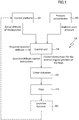
- Figure 1 shows a functional block diagram and the related operational logics of an attitude control and thrust boosting system 100 according to a non-limiting embodiment.
- the attitude control and thrust boosting system 100 is installed on a space launcher, preferably on a stage, for instance the first stage, of a multi-stage space launcher.
- the space launcher, or a stage thereof, is equipped with a rocket engine.
- the rocket engine may be, for instance, a solid-propellant rocket engine, a liquid-propellant rocket engine or a hybrid-propellant rocket engine.
- the rocket engine is provided with an exhaust nozzle.
- the exhaust nozzle comprises a divergent portion that is so designed as to make a supersonic gas flow exit through an exit section defined by a given angle of divergence with a longitudinal axis of the rocket engine.
- the longitudinal axis of the rocket engine is a central axis of symmetry of the exhaust nozzle and of the rocket engine.
- the exit section of the nozzle lies on a plane perpendicular to the longitudinal axis of the rocket engine.
- the attitude control and thrust boosting system 100 includes a number N of flaps 110, for example jet flaps.
- the flaps 110 are arranged at the exit section of the nozzle and around it.
- the nozzles are so shaped as to extend the divergent portion of the exhaust nozzle.
- the flaps are mechanically decoupled from the exhaust nozzle.
- the flaps can be actuated in order to take different angular positions with respect to the longitudinal axis of the rocket engine, according to criteria that will be described in greater detail below.
- the flaps 110 are shaped and modeled on a curved surface ideally representing an extension of the divergent portion of the nozzle.
- the attitude control and thrust boosting system 100 conveniently includes also a number N of actuators 120.
- the actuators 120 are linear actuators.
- Each actuator is coupled to a respective flap 110.
- Each actuator is controllable so as to make the respective flap 110 take different angular positions with respect to the longitudinal axis of the rocket engine.
- the attitude control and thrust boosting system 100 also includes a control unit 130 connected to the linear actuators 120 to control the operation thereof.
- the control unit 130 is also connected to an inertial platform 201 installed on the space launcher and configured to detect an actual (i.e. effective) attitude of the launcher and to send one or more (analogical or digital) output signals carrying one or more quantities indicative of the detected actual attitude, for example an actual attitude angle.
- the inertial platform may be for instance based on the use of gyroscopes.
- the control unit 130 is also connected to a pressure sensing device 202, for instance a piezoelectric or a potentiometric transducer, installed on the space launcher and configured to measure the ambient static pressure and to send one or more (analogical or digital) exit signals carrying one or more quantities indicative of the measured ambient static pressure.
- a pressure sensing device 202 for instance a piezoelectric or a potentiometric transducer, installed on the space launcher and configured to measure the ambient static pressure and to send one or more (analogical or digital) exit signals carrying one or more quantities indicative of the measured ambient static pressure.
- control unit 130 is connected to the inertial platform 201 to receive one or more signals sent by the inertial platform 201, and therefore to receive one or more quantities indicative of the actual attitude of the launcher.
- the control unit 130 is also configured to store or to calculate or to receive (for example, from a flight control system of the launcher) one or more quantities indicative of an attitude required for the space launcher, for example a required attitude angle.
- the control unit 130 is also connected to the pressure sensing device 202 to receive one or more signals sent by the pressure sensing device 202 and therefore to receive one or more quantities indicative of the measured ambient static pressure.
- control unit 130 is configured to control the linear actuators 120, conveniently by sending suitable control instructions for controlling the neutral angular position of the flaps.
- control unit 130 is so configured as to make the flaps 110 take a neutral angular position where the flaps 110 are inclined, to the longitudinal axis of the rocket engine, at an inclination angle greater than, or equal to, the given angle of divergence.
- control unit 130 is so configured as to control the linear actuators 120 in such a manner as to control the neutral angular position taken by the flaps 110 according to the measured ambient static pressure and, therefore, to the flight height corresponding to the measured ambient static pressure.
- the control unit 130 is also so configured as to control the linear actuators 120, by sending suitable control instructions for controlling the attitude of the launcher, so as to make one or more flaps 110 take an angular position different than the neutral angular position, according to the actual attitude of the space launcher and to the required attitude for the space launcher.
- control means 130 are so configured as to control the neutral angular position taken by the flaps 110 by decreasing the inclination angle as the ambient static pressure decreases.
- control unit 130 is so configured as: to reduce the inclination angle as the ambient static pressure decreases until said inclination angle corresponds to said angle of divergence of the nozzle; and then to keep the inclination angle equal to the given angle of divergence independently of the ambient static pressure.
- control unit 130 is so configured as:
- the control unit 130 is so configured as to make one or more of the flaps 110 take an angular position different than the neutral angular position by comparing the actual attitude of the space launcher and the attitude required for the space launcher, for instance, by checking if the actual attitude angle and the required attitude angle are equal to each other or if they differ more than a preset threshold. If the actual attitude and the required attitude differ (or differ more than a preset threshold), based on said actual attitude and said required attitude, the central control unit 130 can determine an angular position where one or more of the flaps deflect the supersonic gas flow exiting the exit section so as to bring the actual attitude towards the required attitude. Once this angular position of one or more flaps has been determined, the central unit 130 can control the actuators of the flap(s) in order to make them take the given angular position.
- control unit 130 may be configured so that, if the actual attitude of the launcher and the required attitude differ, the following steps are performed:
- control of the position taken by the flaps 110 implemented by the control unit 130 through the linear actuators 120, have the double function of controlling the attitude of the launcher based on the actual attitude and the required attitude; and of controlling the neutral angular position, based on the ambient static pressure, i.e. on the flight level.
- Figure 1 also shows a block 203 called "Dynamics of the launcher" in order to represent conceptually (in a clear way, known to those skilled in the art) the dynamic behavior of the space launcher resulting from the control of the position taken by the flaps 110 implemented by means of the control unit 130, so that the inertial platform 201 detects the actual attitude of the launcher resulting from said dynamic behavior.
- the control unit 130 implements the type 1 operational mode and performs the control of both the attitude of the launcher and the neutral angular position, varying the neutral angular position as the ambient static pressure decreases, i.e. as the flight height increases, up to achieve a preset reference angular position corresponding to an inclination of the flaps 110, with respect to the longitudinal axis of the rocket engine, substantially equal to that of the given angle of divergence characterizing the exit section of the nozzle.
- This preset reference angular position is also associated with the preset ambient static pressure threshold corresponding to the above mentioned preset threshold height.
- control unit 130 implements the type 2 operational mode, and performs only the control of the attitude of the launcher, whilst, in the absence of attitude control commands, the flaps 110 are kept in the preset reference angular position.
- the law based on which, in the type 1 operational mode, the neutral angular position of the flaps 110 is determined according to the ambient static pressure depends on the features of the specific fluid-dynamic field existing inside and outside the nozzle and can be therefore conveniently defined case by case based on CFD (computational fluid dynamics) simulations and/or experimental tests.
- the control unit 130 may be configured so as to determine the neutral angular position of the N flaps 110, i.e. the inclination angle to the longitudinal axis of the rocket engine, by executing a first preset calculation function, or using a first preset lookup table, where values are stored of the inclination angle associated with respective height values, i.e. values of ambient static pressure.
- control unit 130 can be conveniently configured to determine the angular positions of the flaps 110 for the attitude control by executing a second preset calculation function, or using a second preset lookup table.
- control of the attitude of the launcher and that of the neutral angular position may be implemented by a single processing and control unit, as shown in Figure 1 , programmed through a suitable software and/or firmware.
- two distinct units may be provided.
- a first unit is dedicated to controlling the attitude and is therefore suitably programmed to implement said attitude control based on the actual attitude of the launcher and on the required attitude.
- a second unit is dedicated to controlling the neutral angular position and is therefore suitably programmed to implement said control of the neutral angular position of the flaps 110 based on the ambient static pressure.
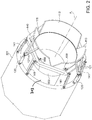
- FIG. 2 is an axonometric view of a lower portion of a stage (for instance the first stage) of a multi-stage space launcher.
- the stage includes an outer structure 301 and a rocket engine provided with an exhaust nozzle.
- a divergent portion 302 of the exhaust nozzle is shown.
- 303 schematically indicates the rocket engine, the end part of which is shown, and which can be designed in a manner known to those skilled in the art.
- the rocket engine may be a solid-propellant rocket engine.
- the rocket engine may be a liquid-propellant rocket engine or also a hybrid-propellant rocket engine.
- the divergent portion 302 is substantially a truncated cone.
- the divergent portion 302 ends with an exit section from which, in use, the supersonic gas flow exits.
- Said exit section is characterized by a given angle of divergence with respect to a longitudinal axis A L of the rocket engine, i.e. a central symmetry axis of the exhaust nozzle and of the rocket engine.
- the flaps 110 are three jet flaps 111, 112, 113 having curved shape ideally forming an extension of the divergent shape of the divergent portion 302 of the nozzle.
- the flaps 111, 112, 113 are shaped so as to form an extension of the divergent portion 302.
- the jet flaps 111, 112, 113 are arranged at 120° from one another in a plane orthogonal to the longitudinal axis A L of the rocket engine and are advantageously provided with a suitable thermal insulation, both on the inner surfaces and on the outer surfaces.
- the jet flaps 111, 112, 113 are hinged to a support structure 140 extending around the exit section of the divergent portion 302 of the nozzle substantially on a plane orthogonal to the axis A L .
- the support structure 140 is hexagonal. Also the support structure 140 is advantageously provided with a suitable thermal insulation of all the surfaces.
- the support structure 140 is fixed to the outer structure 301 of the launcher stage, for example to an engine flange or an inter-stage flange, as in the case of Figure 2 , or to a so-called engine skirt.
- the support structure 140 may be attached to the outer structure 301 by means of a plurality of support rods 141.
- six hinged rods are provided that can be adjusted in length by means of worms at the eyelets at the respective ends thereof.
- Each jet flap 111, 112, 113 can be connected to the support structure 140 by means of a respective pair of traditional hinges 150, as shown in the example of Figure 2 .
- spherical joints may be used for rotating each jet flap 111, 112, 113.
- each linear actuator 120 is connected, at a side, to a hinge fixed on the outer structure 301 of the launcher stage. At the other side, each linear actuator 120 is connected to a movable hinge integral with a pair of V-shaped joists for connecting to the respective jet flap 111, 112, 113.
- connection structure between each jet flap 111, 112, 113 and the movable part of the respective linear actuator 120 is constituted by a pair of V-shaped joists 121, provided with suitable thermal insulation on all the surfaces, whose vertex is hinged to the movable part of the respective linear actuator 120, whilst the other two ends are integrally fixed to the outer surface of the respective jet flap 111, 112, 113.
- the support structure 140 could also have a different shape than the hexagonal shape and could be fixed to the outer structure 201 of the stage through support means different than the support rods 141, for example through support joists.
- the actuators 120 may be designed using different technologies.
- electro-mechanical actuators can be used, or hydraulic actuators, pneumatic actuators etc., of the linear or rotary type or of any other type.
- the support structure 140 on which the jet flaps 111, 112, 113 are hinged, practically avoids any mechanical interface between the nozzle and said jet flaps 111, 112, 113, that are therefore mechanically decoupled from the nozzle. In this way, in use, the jet flaps 111, 112, 113, the support structure 140 and therefore the outer structure 301 of the launcher stage are subjected to structural loads, but not the nozzle.
- the jet flaps 111, 112, 113 are in the reference angular position, i.e. the neutral angular position for high flight heights, where the jet flaps represent an extension of the exhaust nozzle of the rocket engine.
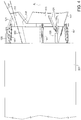
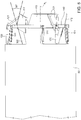
- Figures 3 , 4 , 5 and 6 are side views of Figure 2 .
- the jet flaps 111, 112, 113 are in the reference angular position, i.e. in the neutral angular position for the high flight heights.
- the jet flaps 111, 112, 113 are deflected outwards by 10° with respect to the reference angular position.
- the attitude of the jet flaps 111, 112, 113 shown in Figure 4 may be an example simply indicative of a possible neutral angular position at height zero.
- the jet flap 111 is deflected inwards by 30° with respect to the reference angular position, whilst the other flaps are in the angular position of Figure 4 .
- the jet flaps 111 and 113 are deflected inwards by 30° with respect to the reference angular position.
- dash-dot-lines represent the divergent profile of the divergent portion 302 of the nozzle at the jet flap 111, so as simply to illustrate the concept of reference angular position and to allow a better understanding of the alignment ( Figure 3 ), or of any deflection outwards ( Figure 4 ) or inwards ( Figures 5 and 6 ) of said jet flap 111 with respect to the reference angular position.
- inter-flap panels can be used arranged at said spaces.
- Figures 7 and 8 illustrate a second preferred non-limiting embodiment of the present invention, where the components of the attitude control and thrust boosting system 100 already shown in Figures 2 , 3 , 4 , 5 and 6 and previously described are identified by the same reference numbers used in Figures 2-6 and will not be described again.
- inter-flap panels 160 are used, that are hinged to the support structure 140 at the gaps between the jet flaps 111, 112, 113.
- Resilient load members for example springs, in particular helical springs, may be associated to the connection hinges between inter-flap panels 160 and support structure 140, to load resiliently the inter-flap panels.
- each inter-flap panel 160 interacts with the two flaps adjacent thereto as described below. If the two jet flaps adjacent to an inter-flap panel 160 are in the neutral angular position, the inter-flap panel 160 remains in contact with both said adjacent jet flaps.
- each inter-flap panel 160 is hinged to a respective hinge 161 constrained to the support structure 140 in correspondence of the gap between two respective adjacent jet flaps 111, 112, 113.
- one or more springs are conveniently inserted, for instance torsion helical springs (not shown in Figures 7 and 8 for the sake of simplicity of drawing).
- the function of the springs is to generate on the inter-flap panel 160 a torque rotationally biasing the inter-flap panel towards the longitudinal axis A L of the rocket engine, and therefore to generate a pre-load through which the inter-flap panel rests on one or both the jet flaps 111, 112, 113 adjacent thereto.
- inter-flap panels 160 are conveniently provided with suitable thermal insulation and have curved shape adapted to the shape of the jet flaps 111, 112, 113.
- the plan projection of each inter-flap panel 160 is substantially an isosceles trapezoid.
- T m • V e + A e P e ⁇ P a
- ⁇ indicates the mass flow of the gases exiting from the nozzle
- Ve indicates the speed of the gases at the exit section of the nozzle
- a e indicates the area of the exit section of the nozzle
- P e indicates the static pressure of the gases at the exit section of the nozzle
- the flaps 110 are deflected outwards with respect to the reference angular position, corresponding to the angle of divergence of the exit section of the nozzle. In this way it is possible to avoid the detachment of the limit layer from the inner walls of the divergent portion of the nozzle.
- the flaps 110 are deflected to the reference angular position, thus practically extending the divergent portion of the nozzle and therefore increasing the expansion ratio thereof, without in this case incurring in the problems due to the over-expansion of the supersonic flow that would occur at lower heights, as mentioned above. Consequently, the increase in said expansion ratio of the nozzle entails a thrust and specific impulse boosting with respect to the case in which the invention is not used.
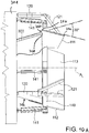
- FIG. 10A , 10B , 11 and 12 A further particular aspect of the structure of the exhaust nozzle and of the flaps is shown specifically in Figures 10A , 10B , 11 and 12 , that will be described in detail below. More in particular Figures 10A and 10B show an enlarged detail of the rear part of the launcher, with the exhaust nozzle 352 and the flaps 111, 112, 113. The position of the flaps corresponds to that of Figures 4 and 5 .
- Figures 10A , 10B a part of the divergent portion 302 of the exhaust nozzle 352 and one of the flaps (flap 111) are shown in a cross-section according to a plane containing the longitudinal axis A L of the exhaust nozzle 352 and of the rocket engine 303.
- reference number 358 indicates the final edge or trailing edge of the divergent portion 302 of the exhaust nozzle 352
- reference number 354 indicates the leading edge, or first edge, of the flaps
- number 356 indicates the trailing edge of the flaps 111, 112, 113.
- a space or gap 360 is formed between the trailing edge 358 of the divergent portion 302 of the exhaust nozzle 352 and the leading edge 354 of each flap 111, 112, 113 .
- the gap 360 connects the volume inside the arrangement formed by the divergent portion 302 of the exhaust nozzle 352 and the flaps 111, 112, 113 with the outer volume, i.e. with the surrounding space, where the launcher moves under the thrust of the rocket engine. Consequently, there is no sealing closure between the divergent portion 302 of the exhaust nozzle 352.
- the opening or gap 360 is maintained, and its width is larger or smaller according to the angular position of the flaps.
- the low pressure of the exhaust gases inside the volume delimited by the divergent portion 302 and by the flaps 111, 112, 113 causes a suction of outer air, due to the so-called ejector effect.
- This flow of outer air sucked through the gap 360 by the exhaust gases of the rocket engine causes an increase in the static pressure on the inner wall of the flaps.
- the air sucked from the outside thanks to the ejector effect through the gap 360 between each flap 111, 112, 113 and the divergent portion 302 has also the advantage of reducing the temperature on the inner wall of the flaps.
- Figures 10A , 10B the gap 360 is shown in a configuration without the inter-flap panels 160.
- Figures 11 and 12 show axonometric views of the end portion of the launcher taken from the side of the rocket engine, where the divergent portion 302 of the exhaust nozzle 352 and the arrangement of flaps 111, 112, 113 and of inter-flap panels 160 are shown, as well as the respective support structure 140. More in particular, in Figure 11 the flaps 111, 112, 113 are arranged in a divergent position with respect to the exhaust nozzle 352.
- the flaps 111, 112, 113 are arranged as in Figure 8 , with the same inclination as the divergent portion 302 of the exhaust nozzle 352, and more precisely with the inclination of the tangent to the exhaust nozzle 352 at the trailing edge thereof.
- the gap 360 is shown, formed between the trailing edge 358 of the exhaust nozzle 352 and the leading edge 354 of the flaps 111, 112, 113.
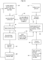
- FIG. 13A , 13B , 13C , 14 and 15 show block diagram schematizing the control method.
- control algorithm For each flap 111, 112, 113 the control algorithm comprises the two following distinct functions:
- the sensors used to obtain the input data for running the algorithm may comprise the following:
- the input data required for the calculation of the desired static pressure, at the trailing edge of the flap, i.e. for the calculation of [(P S ) FTE ] Target are the following:
- the calculation of the target static pressure inside the trailing edge of the flap i.e. of [(P S ) FTE ] Target requires, as a prerequisite, the prediction of the corresponding flow separation static pressure on the inner side of the trailing edge of the flap indicated with (P SEP ) FTE .
- the separation static pressure can be suitably determined by means of a criterion of flow separation for rocket nozzles, using for example: the ambient static pressure and the values of the local Mach number of the flow and/or of any other flow parameter required.
- the functions comprised in the algorithm can be determined experimentally and/or through Computational Fluid Dynamics (CFD) simulations.
- CFD Computational Fluid Dynamics
- Figures 13A , 13B , 13C show a block diagram of the process for calculating the neutral angular position of the flaps with the algorithm summarized above. More in particular, Figure 13A shows: an ambient static pressure sensor 401, a static pressure sensor on the trailing edge 403 of the flaps, a group of transducers of static and total pressure at the trailing edge of the flaps, for example Pitot probes, indicated as a whole with reference number 405.
- Reference number 407 indicates a block for calculating the target static pressure at the trailing edge of the flaps.
- Reference number 409 indicates a block for calculating the neutral angular position of the flaps.
- the block diagram of Figure 13A shows, with the symbols indicated above, the measured and calculated parameters from the sensors and the calculation blocks.
- FIG 13B the block 407 for calculating the flow separation static pressure at the trailing edge of the flaps is shown in greater detail.
- the input parameters are those indicated in Figure 13A .
- the measured parameters are indicated with the same symbols used in Figure 13A and in the description above, without the subscript "Meas”.
- reference number 411 indicates a block for calculating the flow separation static pressure at the trailing edge of the flaps (P SEP ) FTE . This block uses the measured ambient static pressure and the Mach number at the trailing edge of the flaps as input data.
- the output of the block 411 is used in the block 413 for calculating the target static pressure [(P S ) FTE ] Target, by applying the safety margin ( ⁇ P S ) Margin .
- the Mach number given by the ratio between the gas speed and the speed of sound at the trailing edge of the flaps, calculated by the block 413, requires to know the speed of the gas at the trailing edge of the flaps, indicated with V FTE , calculated by a calculation block 421, based on measured parameters of static and total pressure at the trailing edge of the flaps, as well as based on the gas density - indicated with ⁇ FTE - at the trailing edge of the flaps.
- This latter is calculated by a block 419 for calculating the density based on data on static pressure and static temperature measured at the trailing edge of the flaps.
- the parameter R in the block 419 is the constant of the gas flowing on the inner wall of the trailing edge of the flap.
- the speed of sound a FTE at the trailing edge of the flaps is calculated by a block 417 based on the static temperature measured at the trailing edge of the flaps and on the specific heats ratio ⁇ and constant R of the gas.
- Figure 13C illustrates in greater detail the block 409 for calculating the neutral angular position of the flaps.
- This block calculates an error ( ⁇ P S ) Error between the target static pressure [(P S ) FTE ] Target , i.e. the static pressure desired at the trailing edge of the flaps, and the measured static pressure [(P S ) FTE ] Meas at the trailing edge of the flaps.
- the error value calculated is applied to a controller 423 that determines the target neutral angular position ( ⁇ DAP ) Target .
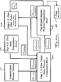
- FIG. 14 The block diagram of Figure 14 represents, similarly to Figure 1 but in greater detail, the control system as a whole. More in particular, in Figure 14 the following blocks are shown: a block 451 indicative of the sensors of static and total pressure at the trailing edge of the flaps 111, 112, 113; a block 453 representing the pressure transducers connected to the sensors of the block 451; a block 455 executing the above described algorithm for calculating the neutral angular position of the flaps ( ⁇ DAP ); a block 457 representing the ambient static pressure sensor; a block 459 representing the pressure transducer associated with the ambient static pressure sensor; a block 460 representing a flow static temperature sensor at the trailing edge of the flaps; a block 461 representing the actuation loop of the flaps 111, 112, 113; a block 463 representing the deflection angles required for the flaps, imparted by the actuators of the block 461; a block 465 determining the required attitude angle for the launcher, based on the guide function exerted
- the set of blocks in Figure 14 execute the control of the neutral angular position of the flaps according to the algorithm described with reference to Figures 13A , 13B , 13C and the control of the attitude of the launcher, sending commands to the actuators of the flaps 111, 112, 113 (block 461).
- the blocks 451, 453, 457, 459, 460 give the algorithm executed by the block 455 the parameters necessary for calculating the neutral position of the flaps 111, 112, 113.
- the block 455 is therefore functionally connected to the block 463 representing the actuation loop of the flaps.
- the inertial platform represented by the block 473 provides data on the measurement of the actual attitude of the launcher, and the block 465 provides information on the target attitude of the launcher.
- the signals are given to the actuators of the flaps in the block 461 that cause the actuation of the flaps to modify the attitude of the launcher.
- the inertial platform 473 executes the measurement of the current (actual) attitude of the launcher following changes to the attitude obtained through the flaps.
- the attitude control is practically performed as follows.
- the inertial platform 473 measures the attitude angles of the launcher and more precisely the pitch angle and the yaw angle.
- the on-board computer (block 465) compares the measured attitude angles and the target ones and sends to the attitude control unit 471 the target deflection values for the various flaps (three in the illustrated example). These angles take into account the neutral angular position calculated according to the flight height ( Figures 13A-13C ).
- the actuation loop acts on the actuators of the flaps modifying the angular position of each flap independently of the other flaps, as required, so as to generate the torque necessary to the launcher to achieve the target attitude.
- the present disclosure also concerns a thrust device for a space launcher, comprising: an exhaust nozzle having a divergent portion able to make a supersonic gas flow exit through an exit section defined by a given angle of divergence with respect to a longitudinal axis of the exhaust nozzle.
- the thrust device further comprises a plurality of flaps, arranged around the exit section. Said flaps are shaped so as to extend the divergent portion of the exhaust nozzle, are mechanically decoupled from said exhaust nozzle and are operable to take different angular positions with respect to the longitudinal axis of the exhaust nozzle.
- the flaps are hinged to a support structure, configured to be constrained to an outer structure of the space launcher.
- the support structure is provided at the exit section of the exhaust nozzle and extends around said exit section.
- the flaps are hinged to the support structure so that they can be actuated in order to take different angular positions with respect to the longitudinal axis of the exhaust nozzle.
- Each flap is associated with a respective actuator.
- the flaps are arranged aligned with one another on a single level without overlapping one another, forming a gap between each pair of adjacent flaps.
- a plurality of inter-flap panels are provided, each of which is hinged to the support structure at a gap between two respective flaps and is passively biased so as to remain in contact with at least one of the respective flaps between which said gap is formed.
- the device can further comprise a resilient pre-load member for each inter-flap panel, adapted to push the inter-flap panel to rest on at least one of the adjacent flaps.
- the exhaust nozzle and the flaps can be arranged so that, in at least some angular positions of the flaps between a trailing edge of the divergent portion of the exhaust nozzle and a leading edge of each flap a gap is formed which places an inner volume defined by the exhaust nozzle and the flaps in communication with a space outside the nozzle and the flaps, said gap being so configured that in at least one angular position of the flaps the flow of gas exhausted from the nozzle generates suction of outer air.
- a gap is formed between a trailing edge of the divergent portion of the exhaust nozzle and the leading edge of each flap.
- the gap connects the volume inside the arrangement formed by the divergent portion of the exhaust nozzle and the flaps with the surrounding space, where the launcher moves under the thrust of the thrust device.
- the exhaust nozzle and the flaps are arranged so that, in at least some angular positions of the flaps between a trailing edge of the divergent portion of the exhaust nozzle and a leading edge of each flap a gap is formed, which places an inner volume defined by the exhaust nozzle and the flaps in communication with a space outside the nozzle and the flaps, said gap being so configured that in at least one angular position of the flaps the flow of gas exhausted from the nozzle generates suction of outer air.
- a gap is formed between a trailing edge of the divergent portion of the exhaust nozzle and the leading edge of each flap.
- the gap connects the volume inside the arrangement formed by the divergent portion of the exhaust nozzle and the flaps with the surrounding space, where the launcher moves under the thrust of the thrust device.
Landscapes
- Engineering & Computer Science (AREA)
- Chemical & Material Sciences (AREA)
- Combustion & Propulsion (AREA)
- Mechanical Engineering (AREA)
- General Engineering & Computer Science (AREA)
- Remote Sensing (AREA)
- Aviation & Aerospace Engineering (AREA)
- Toys (AREA)
- Physics & Mathematics (AREA)
- Plasma & Fusion (AREA)
- Testing Of Engines (AREA)
Claims (20)
- Lageregelungs- und Schubverstärkungssystem (100) für eine Weltraumträgerrakete, umfassend ein Raketentriebwerk (303), das mit einer Schubdüse (352) versehen ist; wobei die Schubdüse (352) einen divergenten Teil (302) umfasst, der eingerichtet ist, einen Überschallgasstrom zum Austreten durch einen Austrittsabschnitt, der durch einen gegebenen Divergenzwinkel hinsichtlich einer Längsachse (AL) des Raketentriebwerks definiert ist, zu veranlassen; wobei das Lageregelungs- und Schubverstärkungssystem (100) umfasst:- eine Anzahl an Klappen (110, 111, 112, 113), die um den Austrittsabschnitt angeordnet sind, so geformt, dass sie den divergenten Teil der Schubdüse verlängern, mechanisch entkoppelt von der Schubdüse, und die betätigt werden können, um unterschiedliche Winkelpositionen hinsichtlich der Längsachse des Raketentriebwerks einzunehmen; und- Steuerungsmittel (130), eingerichtet zum- Empfangen von Größen, die eine tatsächliche Lage der Weltraumträgerrakete und einen statischen Umgebungsdruck anzeigen,- Veranlassen der Klappen (110, 111, 112, 113) zum Einnehmen einer neutralen Winkelposition, in welcher die Klappen (110, 111, 112, 113) hinsichtlich der Längsachse des Raketentriebwerks gemäß einem Inklinationswinkel größer oder gleich dem gegebenen Divergenzwinkel geneigt sind,- Steuern der neutralen Winkelposition, die durch die Klappen (110, 111, 112, 113) eingenommen wird, gemäß dem statischen Umgebungsdruck durch Verringern des Inklinationswinkels, während der statische Umgebungsdruck abnimmt, und- Veranlassen einer oder mehrerer Klappen (110, 111, 112, 113) zum Einnehmen einer Winkelposition, die sich von der neutralen Winkelposition unterscheidet, gemäß der tatsächlichen Lage der Weltraumträgerrakete und einer geforderten Lage für die Weltraumträgerrakete.
- System gemäß Anspruch 1, wobei das Steuerungsmittel (130) eingerichtet ist zum:- Verringern des Inklinationswinkels, während der statische Umgebungsdruck abnimmt, bis zum Einstellen des Inklinationswinkels, sodass er mit dem gegebenen Divergenzwinkel übereinstimmt,- dann Beibehalten des Inklinationswinkels, der dem gegebenen Divergenzwinkel gleicht, unabhängig von dem statischen Umgebungsdruck.
- System gemäß Anspruch 2, wobei das Steuerungsmittel (130) eingerichtet ist zum:- wenn der statische Umgebungsdruck größer ist als ein voreingestellter Schwellwert, Verringern des Inklinationswinkels unter Bestimmung, für jeden neuen gegenwärtigen Wert des statischen Umgebungsdrucks, eines entsprechenden gegenwärtigen Wertes des Inklinationswinkels, um keine Überexpansion des Überschallstroms zu erzeugen;- wenn der statische Umgebungsdruck dem voreingestellten Schwellwert entspricht, Einstellen des Inklinationswinkels, sodass er mit dem gegebenen Divergenzwinkel übereinstimmt;- dann Beibehalten des Inklinationswinkels, der dem gegebenen Divergenzwinkel gleicht, unabhängig von dem statischen Umgebungsdruck.
- System gemäß einem der vorhergehenden Ansprüche, wobei das Steuerungsmittel (130) dazu eingerichtet ist, eine Klappe (110, 111, 112, 113) zum Einnehmen einer Winkelposition zu veranlassen, die sich von der neutralen Winkelposition unterscheidet:- durch Vergleichen der tatsächlichen Lage der Weltraumträgerrakete und der erforderten Lage für die Weltraumträgerrakete; und,- falls sich die tatsächliche Lage von der erforderten Lage unterscheidet,- durch Bestimmen, basierend auf der tatsächlichen Lage und der erforderten Lage, einer Winkelposition, in der die Klappe (110, 111, 112, 113) den Überschallgasstrom, der aus dem Austrittsabschnitt austritt, so ablenkt, dass die tatsächliche Lage in Richtung der erforderten Lage gebracht wird, und- durch Veranlassen der Klappe (110, 111, 112, 113) zum Einnehmen der gegebenen Winkelposition.
- System gemäß einem der vorhergehenden Ansprüche, wobei das Steuerungsmittel (130) verbunden ist mit:- einer Trägheitsplattform (201), die an der Weltraumträgerrakete installiert ist und zum Erfassen der tatsächlichen Lage der Weltraumträgerrakete eingerichtet ist; und- einer Drucksensorvorrichtung (202), die an der Weltraumträgerrakete installiert ist und zum Messen des statischen Umgebungsdrucks eingerichtet ist.
- System gemäß einem der vorhergehenden Ansprüche, wobei das Steuerungsmittel (130) zum Bestimmen, zum Empfangen oder zum Speichern einer oder mehrerer Größen, welche die erforderte Lage der Weltraumträgerrakete angeben, eingerichtet ist.
- System gemäß einem der vorhergehenden Ansprüche, wobei die Klappen (110, 111, 112, 113) an einer Trägerstruktur (140) gelenkig gelagert sind, die an einer äußeren Struktur (301) der Weltraumträgerrakete gehalten wird, an dem Austrittsabschnitt angeordnet ist und sich um den Austrittsabschnitt herum erstreckt; wobei die Klappen (110, 111, 112, 113) an der Trägerstruktur (140) gelenkig gelagert sind, sodass sie betätigt werden können, um unterschiedliche Winkelpositionen hinsichtlich der Längsachse des Raketentriebwerks einzunehmen; und wobei das System bevorzugt weiter eine Anzahl an Zwischenklappenplatten (160) umfasst, von denen jede an der Trägerstruktur (140) an einer Lücke zwischen zwei jeweiligen angrenzenden Klappen (110, 111, 112, 113) gelenkig gelagert ist und so entworfen ist, dass sie immer in Kontakt mit mindestens einer der jeweiligen angrenzenden Klappen (110, 111, 112, 113) bleibt.
- System gemäß einem der vorhergehenden Ansprüche, das weiter eine Anzahl an Stellantrieben (120) umfasst, die:- an einer äußeren Struktur (301) der Weltraumträgerrakete fixiert sind;- mit den Klappen (110, 111, 112, 113) verbunden sind und betreibbar sind, sodass sie die Klappen (110, 111, 112, 113) unterschiedliche Winkelpositionen hinsichtlich der Längsachse des Raketentriebwerks einnehmen lassen; und- mit dem Steuerungsmittel (130) zur Betätigung durch das Steuerungsmittel (130) verbunden sind.
- System gemäß einem der vorhergehenden Ansprüche, wobei der Austrittsabschnitt auf einer Ebene liegt, die senkrecht zu der Längsachse des Raketentriebwerks ist, und wobei die Längsachse des Raketentriebwerks eine zentrale Symmetrieachse der Schubdüse und des Raketentriebwerks ist.
- System gemäß einem der Ansprüche 1 bis 6, wobei die Klappen (110, 111, 112, 113) an einer Trägerstruktur (140) gelenkig gelagert sind, die eingerichtet ist, an einer äußeren Struktur (301) der Weltraumträgerrakete gehalten zu werden; wobei die Trägerstruktur (140) an dem Austrittsabschnitt der Schubdüse bereitgestellt ist und sich um den Austrittsabschnitt herum erstreckt; wobei die Klappen (110, 111, 112, 113) an der Trägerstruktur (140) gelenkig gelagert sind, sodass sie betätigt werden können, um unterschiedliche Winkelpositionen hinsichtlich der Längsachse der Schubdüse einzunehmen; und wobei jede Klappe (110, 111, 112, 113) mit einem jeweiligen Stellantrieb (120) verbunden ist; wobei die Klappen miteinander fluchtend auf einer einzigen Ebene, ohne einander zu überlappen, angeordnet sind, eine Lücke zwischen jedem Paar angrenzender Klappen formen; und wobei eine Anzahl an Zwischenklappenplatten (160) bereitgestellt sind, von denen jede an der Trägerstruktur (140) an einer Lücke zwischen zwei jeweiligen Klappen (110, 111, 112, 113) gelenkig gelagert ist und passiv vorgespannt ist, sodass sie in Kontakt mit mindestens einer der jeweiligen Klappen (110, 111, 112, 113), zwischen denen die Lücke geformt ist, bleibt.
- System gemäß Anspruch 10, das weiter ein elastisches Vorspannungselement für jede Zwischenklappenplatte (160) umfasst, das angepasst ist, die Zwischenklappenplatte (160) zum Anliegen an mindestens einer der angrenzenden Klappen zu drücken.
- System gemäß einem oder mehreren der Ansprüche 10 oder 11, wobei die Schubdüse und die Klappen (111, 112, 113) so angeordnet sind, dass in mindestens einigen Winkelpositionen der Klappen (111, 112, 113) zwischen einer Hinterkante (358) des divergenten Teils (302) der Schubdüse (352) und einer Vorderkante (354) jeder Klappe (110, 111, 112, 113) eine Lücke (360) geformt wird, die ein inneres Volumen, das durch die Schubdüse und die Klappen definiert ist, in Verbindung mit einem Raum außerhalb der Düse und der Klappen setzt, wobei die Lücke so eingerichtet ist, dass in mindestens einer Winkelposition der Klappen der Gasstrom, der von der Düse ausgestoßen wird, ein Ansaugen äußerer Luft erzeugt.
- System gemäß einem oder mehreren der Ansprüche 10 bis 12, wobei zwischen einer Hinterkante (358) des divergenten Teils (302) der Schubdüse (352) und der Vorderkante (354) jeder Klappe (111, 112, 113) eine Lücke (360) gebildet wird; wobei die Lücke (360) das Volumen im Inneren der Anordnung, die durch den divergenten Teil (302) der Schubdüse (352) und die Klappen (111, 112, 113) gebildet wird, mit dem umgebenden Raum verbindet, wobei die Trägerrakete sich unter dem Schub der Schubvorrichtung bewegt.
- Weltraumträgerrakete oder eine Stufe einer mehrstufigen Weltraumträgerrakete, ausgerüstet mit dem Lageregelungs- und Schubverstärkungssystem (100) gemäß einem der vorhergehenden Ansprüche.
- Lageregelungs- und Schubverstärkungsverfahren (100) für eine Weltraumträgerrakete, die mit einem Raketentriebwerk ausgerüstet ist, das mit einer Schubdüse versehen ist, die einen divergenten Teil (302) aufweist, der zum Veranlassen eines Überschallgasstromes zum Austreten durch einen Austrittsabschnitt davon, der durch einen gegebenen Divergenzwinkel hinsichtlich einer Längsachse des Raketentriebwerks definiert ist, eingerichtet ist; wobei das Verfahren die folgenden Schritte umfasst:- Empfangen von Größen, die eine tatsächliche Lage der Weltraumträgerrakete und einen statischen Umgebungsdruck anzeigen,- Veranlassen einer Anzahl an Klappen (110, 111, 112, 113), die um den Austrittsabschnitt der Düse angeordnet sind und so geformt sind, dass sie den divergenten Teil der Düse verlängern, zum Einnehmen einer neutralen Winkelposition, in welcher die Klappen (110, 111, 112, 113) hinsichtlich der Längsachse des Raketentriebwerks geneigt sind, gemäß einem Inklinationswinkel gleich dem oder größer als der gegebene Divergenzwinkel,- Steuern der neutralen Winkelposition, die durch die Klappen (110, 111, 112, 113) eingenommen wird, gemäß dem statischen Umgebungsdruck durch Verringern des Inklinationswinkels der Klappen (111, 112, 113), während der statische Umgebungsdruck abnimmt.
- Verfahren gemäß Anspruch 15, das weiter den Schritt umfasst, eine oder mehrere Klappen (110, 111, 112, 113) zu veranlassen, eine Winkelposition einzunehmen, die sich von der neutralen Winkelposition unterscheidet, gemäß der tatsächlichen Lage der Weltraumträgerrakete und einer erforderten Lage der Weltraumträgerrakete.
- Verfahren gemäß Anspruch 15 oder 16, das die Schritte umfasst:- Verringern des Inklinationswinkels der Klappen (111, 112, 113), während sich der statische Umgebungsdruck verringert, um den Inklinationswinkel in Übereinstimmung mit dem gegebenen Divergenzwinkel zu bringen,- dann Beibehalten des Inklinationswinkels, der dem gegebenen Divergenzwinkel gleicht, unabhängig von dem statischen Umgebungsdruck.
- Verfahren gemäß Anspruch 17, das die Schritte umfasst:- wenn der statische Umgebungsdruck größer ist als ein voreingestellter Schwellwert, Verringern des Inklinationswinkels unter Bestimmung, für jeden neuen gegenwärtigen Wert des statischen Umgebungsdrucks, eines entsprechenden gegenwärtigen Wertes des Inklinationswinkels, um keine Überexpansion des Überschallstroms zu erzeugen;- wenn der statische Umgebungsdruck dem voreingestellten Schwellwert entspricht, Einstellen des Inklinationswinkels, sodass er mit dem gegebenen Divergenzwinkel übereinstimmt;- dann Beibehalten des Inklinationswinkels, der dem gegebenen Divergenzwinkel gleicht, unabhängig von dem statischen Umgebungsdruck.
- Verfahren gemäß einem der Ansprüche 15 bis 18, das die Schritte umfasst:Vergleichen einer tatsächlichen Lage der Weltraumträgerrakete und einer erforderten Lage für die Weltraumträgerrakete; und,- falls sich die tatsächliche Lage von der erforderten Lage unterscheidet,- Bestimmen, basierend auf der tatsächlichen Lage und der erforderten Lage, einer Winkelposition, in der mindestens eine der Klappen (110, 111, 112, 113) den Überschallgasstrom, der aus dem Austrittsabschnitt austritt, so ablenkt, dass die tatsächliche Lage in Richtung der erforderten Lage gebracht wird, und- Veranlassen der Klappe (110, 111, 112, 113) zum Einnehmen der gegebenen Winkelposition.
- Computerprodukt, das mindestens einen Teil eines Codes umfasst, der auf ein Verarbeitungsmittel eines Lagersteuerungs- und Schubverstärkungssystems (100), das an einer Weltraumträgerrakete installiert ist, hochgeladen werden kann; wobei der Teil des Codes derart ist, dass, wenn er auf das Verarbeitungsmittel hochgeladen wurde, das Verarbeitungsmittel als das Steuerungsmittel (130) des Lagesteuerungs- und Schubverstärkungssystems (100) gemäß einem der Ansprüche 1 bis 13 eingerichtet wird.
Applications Claiming Priority (2)
| Application Number | Priority Date | Filing Date | Title |
|---|---|---|---|
| IT201700063102 | 2017-06-08 | ||
| PCT/IB2018/054092 WO2018224998A1 (en) | 2017-06-08 | 2018-06-07 | Attitude control and thrust boosting system and method for space launchers |
Publications (2)
| Publication Number | Publication Date |
|---|---|
| EP3634857A1 EP3634857A1 (de) | 2020-04-15 |
| EP3634857B1 true EP3634857B1 (de) | 2021-03-10 |
Family
ID=60294163
Family Applications (1)
| Application Number | Title | Priority Date | Filing Date |
|---|---|---|---|
| EP18739632.0A Active EP3634857B1 (de) | 2017-06-08 | 2018-06-07 | Lageregelungs- und schubverstärkungssystem und verfahren für trägerrakete |
Country Status (4)
| Country | Link |
|---|---|
| US (1) | US11554882B2 (de) |
| EP (1) | EP3634857B1 (de) |
| JP (1) | JP7029527B2 (de) |
| WO (1) | WO2018224998A1 (de) |
Families Citing this family (5)
| Publication number | Priority date | Publication date | Assignee | Title |
|---|---|---|---|---|
| CN113339157B (zh) * | 2021-06-16 | 2022-07-12 | 西安交通大学 | 一种可变推力的微型固体火箭发动机柔性喷管系统 |
| CN115824568A (zh) * | 2022-10-31 | 2023-03-21 | 中国航空工业集团公司北京长城计量测试技术研究所 | 一种航空发动机尾喷管压力测量装置 |
| CN116537975B (zh) * | 2023-07-06 | 2023-10-20 | 北京凌空天行科技有限责任公司 | 一种可回收飞行器喷流控制装置 |
| CN116643482B (zh) * | 2023-07-27 | 2023-10-20 | 航天科工火箭技术有限公司 | 一种运载火箭侧喷流姿态冗余控制方法 |
| CN117268338B (zh) * | 2023-11-17 | 2024-02-13 | 鲁东大学 | 一种海上火箭发射平台姿态倾角测试方法 |
Family Cites Families (9)
| Publication number | Priority date | Publication date | Assignee | Title |
|---|---|---|---|---|
| US3229457A (en) * | 1962-10-15 | 1966-01-18 | James R Rowe | Variable area ratio rocket nozzle |
| US3304722A (en) * | 1965-02-16 | 1967-02-21 | James L Culpepper | Means for supplying cold gas to a propulsion jet in outer space |
| JPH0299751A (ja) | 1988-10-04 | 1990-04-11 | Japan Aircraft Mfg Co Ltd | 展開形ロケットノズル |
| JPH06257512A (ja) | 1993-03-04 | 1994-09-13 | Mitsubishi Heavy Ind Ltd | 可変排気ノズル |
| US6723972B2 (en) * | 2000-12-22 | 2004-04-20 | Lockheed Martin Corporation | Method and apparatus for planar actuation of a flared surface to control a vehicle |
| DE10123731C2 (de) | 2001-05-15 | 2003-08-21 | Astrium Gmbh | Verfahren zur Verlängerung einer Düse und verlängerbare Düse für Raketentriebwerke |
| EP2401204A4 (de) * | 2009-02-24 | 2017-07-05 | Blue Origin, LLC | Abwurffahrzeuge mit festen und abnehmbaren entschleunigungsflächen und/oder geformten brennstofftanks sowie systeme und verfahren dafür |
| FR3009029B1 (fr) | 2013-07-26 | 2018-03-23 | Astrium Sas | Tuyere d'ejection de gaz de combustion d'un moteur fusee pourvue d'un dispositif d'etancheite entre une partie fixe et une partie mobile de la tuyere |
| CN106593696A (zh) | 2016-12-21 | 2017-04-26 | 南京航空航天大学 | 能够改善后体流场的对称及非对称排气系统及其方法 |
-
2018
- 2018-06-07 WO PCT/IB2018/054092 patent/WO2018224998A1/en not_active Ceased
- 2018-06-07 US US16/620,249 patent/US11554882B2/en active Active
- 2018-06-07 EP EP18739632.0A patent/EP3634857B1/de active Active
- 2018-06-07 JP JP2020518594A patent/JP7029527B2/ja active Active
Non-Patent Citations (1)
| Title |
|---|
| None * |
Also Published As
| Publication number | Publication date |
|---|---|
| WO2018224998A1 (en) | 2018-12-13 |
| US11554882B2 (en) | 2023-01-17 |
| US20210147099A1 (en) | 2021-05-20 |
| JP7029527B2 (ja) | 2022-03-03 |
| EP3634857A1 (de) | 2020-04-15 |
| JP2020523256A (ja) | 2020-08-06 |
Similar Documents
| Publication | Publication Date | Title |
|---|---|---|
| EP3634857B1 (de) | Lageregelungs- und schubverstärkungssystem und verfahren für trägerrakete | |
| US3806064A (en) | Missile configurations, controls and utilization techniques | |
| Gal-Or | Fundamental concepts of vectored propulsion | |
| CN120406500A (zh) | 一种进气道不起动的吸气式高超声速飞行器轨迹在线规划方法 | |
| US5172547A (en) | Electronic valve control for gas generator outflow | |
| Pinto et al. | Robust propulsion control in all flight stages of a throtteable ducted rocket | |
| US20190360353A1 (en) | Propulsion system for an aircraft, a nozzle for use with the propulsion system, and a method of manufacturing a propulsion system for an aircraft | |
| US7603842B2 (en) | Method for reducing the nonsteady side loads acting on a nozzle of a rocket engine | |
| Tekin et al. | Modeling and vertical launch analysis of an aero-and thrust vector controlled surface to air missile | |
| EP3812266A1 (de) | Fluidische steuerung | |
| US3692258A (en) | Missile configurations,controls and utilization techniques | |
| Davidović et al. | Contribution to research of spoiler and dome deflector TVC systems in rocket propulsion | |
| Naumann et al. | Hot Gas Nozzle-Valve Assembly and Control Method for Continuously Operating Divert-and Attitude Control Systems | |
| US10982623B2 (en) | Propulsion system for an aircraft, a nozzle for use with the propulsion system, and a method of manufacturing a propulsion system for an aircraft | |
| Tudosie | Pneumo-hydro-mechanical control system for an aircraft supersonic inlet with mobile ramp | |
| Hopfe et al. | Hot Gas Nozzle-Valve Assembly and Control Method for Continuously Operating Divert-and Attitude Control Systems | |
| Majil | Design and analysis of jet vane thrust vectoring nozzle using CFD and optimization of nozzle parameters | |
| Vorob’ev et al. | Rotation of the thrust vector of a two-dimensional nozzle by means of displacing the critical surface | |
| Fomin et al. | Analysis of efficiency of using hybrid propulsion for accelerating small-size rockets starting from the earth surface | |
| AU2020342617B2 (en) | Fluidic control | |
| Cockin et al. | Robust Sliding Mode Control for Air-to-Air Missile | |
| Sadovnychiy et al. | Flight control system damage simulationusing freely flying models | |
| JP2001193564A (ja) | ラムジェットエンジンの制御方法および制御装置 | |
| JP3793811B2 (ja) | エンジン燃料制御装置 | |
| Mayer et al. | Missile propulsion performance modeling in a visual simulation environment |
Legal Events
| Date | Code | Title | Description |
|---|---|---|---|
| STAA | Information on the status of an ep patent application or granted ep patent |
Free format text: STATUS: UNKNOWN |
|
| STAA | Information on the status of an ep patent application or granted ep patent |
Free format text: STATUS: THE INTERNATIONAL PUBLICATION HAS BEEN MADE |
|
| PUAI | Public reference made under article 153(3) epc to a published international application that has entered the european phase |
Free format text: ORIGINAL CODE: 0009012 |
|
| STAA | Information on the status of an ep patent application or granted ep patent |
Free format text: STATUS: REQUEST FOR EXAMINATION WAS MADE |
|
| 17P | Request for examination filed |
Effective date: 20200102 |
|
| AK | Designated contracting states |
Kind code of ref document: A1 Designated state(s): AL AT BE BG CH CY CZ DE DK EE ES FI FR GB GR HR HU IE IS IT LI LT LU LV MC MK MT NL NO PL PT RO RS SE SI SK SM TR |
|
| AX | Request for extension of the european patent |
Extension state: BA ME |
|
| RIN1 | Information on inventor provided before grant (corrected) |
Inventor name: ROSATI, ROBERTO |
|
| DAV | Request for validation of the european patent (deleted) | ||
| DAX | Request for extension of the european patent (deleted) | ||
| GRAP | Despatch of communication of intention to grant a patent |
Free format text: ORIGINAL CODE: EPIDOSNIGR1 |
|
| STAA | Information on the status of an ep patent application or granted ep patent |
Free format text: STATUS: GRANT OF PATENT IS INTENDED |
|
| INTG | Intention to grant announced |
Effective date: 20200930 |
|
| GRAS | Grant fee paid |
Free format text: ORIGINAL CODE: EPIDOSNIGR3 |
|
| GRAA | (expected) grant |
Free format text: ORIGINAL CODE: 0009210 |
|
| STAA | Information on the status of an ep patent application or granted ep patent |
Free format text: STATUS: THE PATENT HAS BEEN GRANTED |
|
| AK | Designated contracting states |
Kind code of ref document: B1 Designated state(s): AL AT BE BG CH CY CZ DE DK EE ES FI FR GB GR HR HU IE IS IT LI LT LU LV MC MK MT NL NO PL PT RO RS SE SI SK SM TR |
|
| REG | Reference to a national code |
Ref country code: GB Ref legal event code: FG4D |
|
| REG | Reference to a national code |
Ref country code: AT Ref legal event code: REF Ref document number: 1369582 Country of ref document: AT Kind code of ref document: T Effective date: 20210315 Ref country code: CH Ref legal event code: EP |
|
| REG | Reference to a national code |
Ref country code: IE Ref legal event code: FG4D |
|
| REG | Reference to a national code |
Ref country code: DE Ref legal event code: R096 Ref document number: 602018013826 Country of ref document: DE |
|
| REG | Reference to a national code |
Ref country code: LT Ref legal event code: MG9D |
|
| PG25 | Lapsed in a contracting state [announced via postgrant information from national office to epo] |
Ref country code: LT Free format text: LAPSE BECAUSE OF FAILURE TO SUBMIT A TRANSLATION OF THE DESCRIPTION OR TO PAY THE FEE WITHIN THE PRESCRIBED TIME-LIMIT Effective date: 20210310 Ref country code: NO Free format text: LAPSE BECAUSE OF FAILURE TO SUBMIT A TRANSLATION OF THE DESCRIPTION OR TO PAY THE FEE WITHIN THE PRESCRIBED TIME-LIMIT Effective date: 20210610 Ref country code: BG Free format text: LAPSE BECAUSE OF FAILURE TO SUBMIT A TRANSLATION OF THE DESCRIPTION OR TO PAY THE FEE WITHIN THE PRESCRIBED TIME-LIMIT Effective date: 20210610 Ref country code: GR Free format text: LAPSE BECAUSE OF FAILURE TO SUBMIT A TRANSLATION OF THE DESCRIPTION OR TO PAY THE FEE WITHIN THE PRESCRIBED TIME-LIMIT Effective date: 20210611 Ref country code: FI Free format text: LAPSE BECAUSE OF FAILURE TO SUBMIT A TRANSLATION OF THE DESCRIPTION OR TO PAY THE FEE WITHIN THE PRESCRIBED TIME-LIMIT Effective date: 20210310 Ref country code: HR Free format text: LAPSE BECAUSE OF FAILURE TO SUBMIT A TRANSLATION OF THE DESCRIPTION OR TO PAY THE FEE WITHIN THE PRESCRIBED TIME-LIMIT Effective date: 20210310 |
|
| REG | Reference to a national code |
Ref country code: AT Ref legal event code: MK05 Ref document number: 1369582 Country of ref document: AT Kind code of ref document: T Effective date: 20210310 |
|
| REG | Reference to a national code |
Ref country code: NL Ref legal event code: MP Effective date: 20210310 |
|
| PG25 | Lapsed in a contracting state [announced via postgrant information from national office to epo] |
Ref country code: LV Free format text: LAPSE BECAUSE OF FAILURE TO SUBMIT A TRANSLATION OF THE DESCRIPTION OR TO PAY THE FEE WITHIN THE PRESCRIBED TIME-LIMIT Effective date: 20210310 Ref country code: RS Free format text: LAPSE BECAUSE OF FAILURE TO SUBMIT A TRANSLATION OF THE DESCRIPTION OR TO PAY THE FEE WITHIN THE PRESCRIBED TIME-LIMIT Effective date: 20210310 Ref country code: SE Free format text: LAPSE BECAUSE OF FAILURE TO SUBMIT A TRANSLATION OF THE DESCRIPTION OR TO PAY THE FEE WITHIN THE PRESCRIBED TIME-LIMIT Effective date: 20210310 |
|
| PG25 | Lapsed in a contracting state [announced via postgrant information from national office to epo] |
Ref country code: NL Free format text: LAPSE BECAUSE OF FAILURE TO SUBMIT A TRANSLATION OF THE DESCRIPTION OR TO PAY THE FEE WITHIN THE PRESCRIBED TIME-LIMIT Effective date: 20210310 |
|
| PG25 | Lapsed in a contracting state [announced via postgrant information from national office to epo] |
Ref country code: CZ Free format text: LAPSE BECAUSE OF FAILURE TO SUBMIT A TRANSLATION OF THE DESCRIPTION OR TO PAY THE FEE WITHIN THE PRESCRIBED TIME-LIMIT Effective date: 20210310 Ref country code: EE Free format text: LAPSE BECAUSE OF FAILURE TO SUBMIT A TRANSLATION OF THE DESCRIPTION OR TO PAY THE FEE WITHIN THE PRESCRIBED TIME-LIMIT Effective date: 20210310 Ref country code: SM Free format text: LAPSE BECAUSE OF FAILURE TO SUBMIT A TRANSLATION OF THE DESCRIPTION OR TO PAY THE FEE WITHIN THE PRESCRIBED TIME-LIMIT Effective date: 20210310 Ref country code: AT Free format text: LAPSE BECAUSE OF FAILURE TO SUBMIT A TRANSLATION OF THE DESCRIPTION OR TO PAY THE FEE WITHIN THE PRESCRIBED TIME-LIMIT Effective date: 20210310 |
|
| PG25 | Lapsed in a contracting state [announced via postgrant information from national office to epo] |
Ref country code: RO Free format text: LAPSE BECAUSE OF FAILURE TO SUBMIT A TRANSLATION OF THE DESCRIPTION OR TO PAY THE FEE WITHIN THE PRESCRIBED TIME-LIMIT Effective date: 20210310 Ref country code: PT Free format text: LAPSE BECAUSE OF FAILURE TO SUBMIT A TRANSLATION OF THE DESCRIPTION OR TO PAY THE FEE WITHIN THE PRESCRIBED TIME-LIMIT Effective date: 20210712 Ref country code: SK Free format text: LAPSE BECAUSE OF FAILURE TO SUBMIT A TRANSLATION OF THE DESCRIPTION OR TO PAY THE FEE WITHIN THE PRESCRIBED TIME-LIMIT Effective date: 20210310 Ref country code: PL Free format text: LAPSE BECAUSE OF FAILURE TO SUBMIT A TRANSLATION OF THE DESCRIPTION OR TO PAY THE FEE WITHIN THE PRESCRIBED TIME-LIMIT Effective date: 20210310 Ref country code: IS Free format text: LAPSE BECAUSE OF FAILURE TO SUBMIT A TRANSLATION OF THE DESCRIPTION OR TO PAY THE FEE WITHIN THE PRESCRIBED TIME-LIMIT Effective date: 20210710 |
|
| REG | Reference to a national code |
Ref country code: DE Ref legal event code: R097 Ref document number: 602018013826 Country of ref document: DE |
|
| PLBE | No opposition filed within time limit |
Free format text: ORIGINAL CODE: 0009261 |
|
| STAA | Information on the status of an ep patent application or granted ep patent |
Free format text: STATUS: NO OPPOSITION FILED WITHIN TIME LIMIT |
|
| PG25 | Lapsed in a contracting state [announced via postgrant information from national office to epo] |
Ref country code: MC Free format text: LAPSE BECAUSE OF FAILURE TO SUBMIT A TRANSLATION OF THE DESCRIPTION OR TO PAY THE FEE WITHIN THE PRESCRIBED TIME-LIMIT Effective date: 20210310 Ref country code: AL Free format text: LAPSE BECAUSE OF FAILURE TO SUBMIT A TRANSLATION OF THE DESCRIPTION OR TO PAY THE FEE WITHIN THE PRESCRIBED TIME-LIMIT Effective date: 20210310 Ref country code: DK Free format text: LAPSE BECAUSE OF FAILURE TO SUBMIT A TRANSLATION OF THE DESCRIPTION OR TO PAY THE FEE WITHIN THE PRESCRIBED TIME-LIMIT Effective date: 20210310 Ref country code: ES Free format text: LAPSE BECAUSE OF FAILURE TO SUBMIT A TRANSLATION OF THE DESCRIPTION OR TO PAY THE FEE WITHIN THE PRESCRIBED TIME-LIMIT Effective date: 20210310 |
|
| REG | Reference to a national code |
Ref country code: CH Ref legal event code: PL |
|
| 26N | No opposition filed |
Effective date: 20211213 |
|
| PG25 | Lapsed in a contracting state [announced via postgrant information from national office to epo] |
Ref country code: SI Free format text: LAPSE BECAUSE OF FAILURE TO SUBMIT A TRANSLATION OF THE DESCRIPTION OR TO PAY THE FEE WITHIN THE PRESCRIBED TIME-LIMIT Effective date: 20210310 |
|
| REG | Reference to a national code |
Ref country code: BE Ref legal event code: MM Effective date: 20210630 |
|
| PG25 | Lapsed in a contracting state [announced via postgrant information from national office to epo] |
Ref country code: LU Free format text: LAPSE BECAUSE OF NON-PAYMENT OF DUE FEES Effective date: 20210607 |
|
| PG25 | Lapsed in a contracting state [announced via postgrant information from national office to epo] |
Ref country code: LI Free format text: LAPSE BECAUSE OF NON-PAYMENT OF DUE FEES Effective date: 20210630 Ref country code: IT Free format text: LAPSE BECAUSE OF FAILURE TO SUBMIT A TRANSLATION OF THE DESCRIPTION OR TO PAY THE FEE WITHIN THE PRESCRIBED TIME-LIMIT Effective date: 20210310 Ref country code: IE Free format text: LAPSE BECAUSE OF NON-PAYMENT OF DUE FEES Effective date: 20210607 Ref country code: CH Free format text: LAPSE BECAUSE OF NON-PAYMENT OF DUE FEES Effective date: 20210630 |
|
| PG25 | Lapsed in a contracting state [announced via postgrant information from national office to epo] |
Ref country code: IS Free format text: LAPSE BECAUSE OF FAILURE TO SUBMIT A TRANSLATION OF THE DESCRIPTION OR TO PAY THE FEE WITHIN THE PRESCRIBED TIME-LIMIT Effective date: 20210710 |
|
| PG25 | Lapsed in a contracting state [announced via postgrant information from national office to epo] |
Ref country code: BE Free format text: LAPSE BECAUSE OF NON-PAYMENT OF DUE FEES Effective date: 20210630 |
|
| PG25 | Lapsed in a contracting state [announced via postgrant information from national office to epo] |
Ref country code: CY Free format text: LAPSE BECAUSE OF FAILURE TO SUBMIT A TRANSLATION OF THE DESCRIPTION OR TO PAY THE FEE WITHIN THE PRESCRIBED TIME-LIMIT Effective date: 20210310 |
|
| PG25 | Lapsed in a contracting state [announced via postgrant information from national office to epo] |
Ref country code: HU Free format text: LAPSE BECAUSE OF FAILURE TO SUBMIT A TRANSLATION OF THE DESCRIPTION OR TO PAY THE FEE WITHIN THE PRESCRIBED TIME-LIMIT; INVALID AB INITIO Effective date: 20180607 |
|
| PG25 | Lapsed in a contracting state [announced via postgrant information from national office to epo] |
Ref country code: MK Free format text: LAPSE BECAUSE OF FAILURE TO SUBMIT A TRANSLATION OF THE DESCRIPTION OR TO PAY THE FEE WITHIN THE PRESCRIBED TIME-LIMIT Effective date: 20210310 |
|
| PG25 | Lapsed in a contracting state [announced via postgrant information from national office to epo] |
Ref country code: TR Free format text: LAPSE BECAUSE OF FAILURE TO SUBMIT A TRANSLATION OF THE DESCRIPTION OR TO PAY THE FEE WITHIN THE PRESCRIBED TIME-LIMIT Effective date: 20210310 |
|
| PG25 | Lapsed in a contracting state [announced via postgrant information from national office to epo] |
Ref country code: MT Free format text: LAPSE BECAUSE OF FAILURE TO SUBMIT A TRANSLATION OF THE DESCRIPTION OR TO PAY THE FEE WITHIN THE PRESCRIBED TIME-LIMIT Effective date: 20210310 |
|
| PGFP | Annual fee paid to national office [announced via postgrant information from national office to epo] |
Ref country code: DE Payment date: 20250626 Year of fee payment: 8 |
|
| PGFP | Annual fee paid to national office [announced via postgrant information from national office to epo] |
Ref country code: GB Payment date: 20250618 Year of fee payment: 8 |
|
| PGFP | Annual fee paid to national office [announced via postgrant information from national office to epo] |
Ref country code: FR Payment date: 20250624 Year of fee payment: 8 |