EP3634818B1 - Image recording device, assembly, cleaning device and motor vehicle - Google Patents
Image recording device, assembly, cleaning device and motor vehicle Download PDFInfo
- Publication number
- EP3634818B1 EP3634818B1 EP18732500.6A EP18732500A EP3634818B1 EP 3634818 B1 EP3634818 B1 EP 3634818B1 EP 18732500 A EP18732500 A EP 18732500A EP 3634818 B1 EP3634818 B1 EP 3634818B1
- Authority
- EP
- European Patent Office
- Prior art keywords
- image recording
- recording device
- cleaning device
- passage
- condition
- Prior art date
- Legal status (The legal status is an assumption and is not a legal conclusion. Google has not performed a legal analysis and makes no representation as to the accuracy of the status listed.)
- Active
Links
Images




Classifications
-
- B—PERFORMING OPERATIONS; TRANSPORTING
- B60—VEHICLES IN GENERAL
- B60S—SERVICING, CLEANING, REPAIRING, SUPPORTING, LIFTING, OR MANOEUVRING OF VEHICLES, NOT OTHERWISE PROVIDED FOR
- B60S1/00—Cleaning of vehicles
- B60S1/02—Cleaning windscreens, windows or optical devices
- B60S1/56—Cleaning windscreens, windows or optical devices specially adapted for cleaning other parts or devices than front windows or windscreens
-
- B—PERFORMING OPERATIONS; TRANSPORTING
- B60—VEHICLES IN GENERAL
- B60S—SERVICING, CLEANING, REPAIRING, SUPPORTING, LIFTING, OR MANOEUVRING OF VEHICLES, NOT OTHERWISE PROVIDED FOR
- B60S1/00—Cleaning of vehicles
- B60S1/02—Cleaning windscreens, windows or optical devices
- B60S1/56—Cleaning windscreens, windows or optical devices specially adapted for cleaning other parts or devices than front windows or windscreens
- B60S1/566—Cleaning windscreens, windows or optical devices specially adapted for cleaning other parts or devices than front windows or windscreens including wiping devices
-
- B—PERFORMING OPERATIONS; TRANSPORTING
- B60—VEHICLES IN GENERAL
- B60R—VEHICLES, VEHICLE FITTINGS, OR VEHICLE PARTS, NOT OTHERWISE PROVIDED FOR
- B60R11/00—Arrangements for holding or mounting articles, not otherwise provided for
- B60R11/04—Mounting of cameras operative during drive; Arrangement of controls thereof relative to the vehicle
-
- B—PERFORMING OPERATIONS; TRANSPORTING
- B60—VEHICLES IN GENERAL
- B60S—SERVICING, CLEANING, REPAIRING, SUPPORTING, LIFTING, OR MANOEUVRING OF VEHICLES, NOT OTHERWISE PROVIDED FOR
- B60S1/00—Cleaning of vehicles
- B60S1/02—Cleaning windscreens, windows or optical devices
-
- B—PERFORMING OPERATIONS; TRANSPORTING
- B60—VEHICLES IN GENERAL
- B60S—SERVICING, CLEANING, REPAIRING, SUPPORTING, LIFTING, OR MANOEUVRING OF VEHICLES, NOT OTHERWISE PROVIDED FOR
- B60S1/00—Cleaning of vehicles
- B60S1/02—Cleaning windscreens, windows or optical devices
- B60S1/56—Cleaning windscreens, windows or optical devices specially adapted for cleaning other parts or devices than front windows or windscreens
- B60S1/60—Cleaning windscreens, windows or optical devices specially adapted for cleaning other parts or devices than front windows or windscreens for signalling devices, e.g. reflectors
- B60S1/603—Cleaning windscreens, windows or optical devices specially adapted for cleaning other parts or devices than front windows or windscreens for signalling devices, e.g. reflectors the operation of at least a part of the cleaning means being controlled by electric means
-
- G—PHYSICS
- G02—OPTICS
- G02B—OPTICAL ELEMENTS, SYSTEMS OR APPARATUS
- G02B27/00—Optical systems or apparatus not provided for by any of the groups G02B1/00 - G02B26/00, G02B30/00
-
- G—PHYSICS
- G02—OPTICS
- G02B—OPTICAL ELEMENTS, SYSTEMS OR APPARATUS
- G02B27/00—Optical systems or apparatus not provided for by any of the groups G02B1/00 - G02B26/00, G02B30/00
- G02B27/0006—Optical systems or apparatus not provided for by any of the groups G02B1/00 - G02B26/00, G02B30/00 with means to keep optical surfaces clean, e.g. by preventing or removing dirt, stains, contamination, condensation
-
- B—PERFORMING OPERATIONS; TRANSPORTING
- B60—VEHICLES IN GENERAL
- B60R—VEHICLES, VEHICLE FITTINGS, OR VEHICLE PARTS, NOT OTHERWISE PROVIDED FOR
- B60R11/00—Arrangements for holding or mounting articles, not otherwise provided for
- B60R2011/0042—Arrangements for holding or mounting articles, not otherwise provided for characterised by mounting means
- B60R2011/008—Adjustable or movable supports
-
- F—MECHANICAL ENGINEERING; LIGHTING; HEATING; WEAPONS; BLASTING
- F28—HEAT EXCHANGE IN GENERAL
- F28G—CLEANING OF INTERNAL OR EXTERNAL SURFACES OF HEAT-EXCHANGE OR HEAT-TRANSFER CONDUITS, e.g. WATER TUBES OR BOILERS
- F28G3/00—Rotary appliances
Definitions
- the invention relates to an image recording device for a body of a motor vehicle, wherein the image recording device comprises an optical element.
- Image recording devices of this type are known and are used, for example, in cars, but also in other motor vehicles.
- the optical element of the image recording device can be or comprise a camera or a part of a camera.
- the image recording device may be configured to offer vision to a driver of the motor vehicle vision, preferably vision of an area located next to or behind the vehicle.
- the image recording device may be configured to offer a driver vision along a flank of the vehicle, of an area next to the driver and/or next to the vehicle and/or behind the vehicle.
- the image recording device may for example be configured and/or be intended for replacement and/or for support of an exterior mirror or so-called wing mirror of a car or other motor vehicle.
- the image recording device may be for a different purpose, for example, for eliminating a blind spot of an exterior mirror, so that a driver of a motor vehicle can be offered a relatively good view of an area that would not be (well) visible in a conventional exterior mirror of a vehicle, such as, for example, the area next to the driver. This may for example prevent a driver overlooking a vehicle overtaking him when he wants to change lane and then, for example, fails to look over his shoulder properly.
- the image recording device may alternatively or additionally be configured and/or intended for assistance in parking.
- the image recording device may for example constitute a so-called backing camera, which can record a relatively large part or even the complete blind spot behind the motor vehicle, which can thereupon, preferably without appreciable or noticeable delay, be displayed to the driver of the vehicle.
- the image recording device may, for example, be merely temporarily activated, for example when the vehicle backs up or when the gearbox of the vehicle is in reverse gear.
- image recording device for the motor vehicle may also, additionally or alternatively, be intended for other purposes and/or be configured therefor.
- a situation should be prevented where the outer surface of the optical element of the image recording device is unintendedly at least temporarily not free of water drops, snow, dirt and/or the like.
- the image recording device is intended and/or configured to offer vision of an area that is not or hardly visible to the driver in any other manner, it is desirable that it can be promoted, or can even be guaranteed, that the outer surface of the optical element is clean or can be rendered clean.
- Document DE 10 2004 220 257 A1 discloses an image recording device of a motor vehicle according to the preamble of claim 1.
- the disclosure therefore envisages providing an alternative image recording device for a motor vehicle and/or an alternative motor vehicle with an image recording device.
- Envisaged in particular is the provision of an image recording device for a motor vehicle and/or a motor vehicle with an image recording device, whereby a condition can be promoted where an outer surface of an optical element of the image recording device is clean enough to be able to record a relatively good image, preferably for display to a driver of the vehicle.
- the present disclosure envisages counteracting any condition where, at least temporarily, it cannot be ensured, or cannot be ensured well enough, that the outer surface is clean enough, can be rendered clean enough and/or can be kept clean enough.
- an image recording device for a body of a motor vehicle comprising a housing part, an optical element having an outer surface, and a driving part for engaging an engaging part of a movable cleaning device, for example a wiper, which movable cleaning device furthermore comprises a cleaning part, for example a wiper part, for at least partly cleaning, for example at least partly wiping, the outer surface, wherein the driving part is furthermore for driving the movable cleaning device in order to have the cleaning part at least partly clean the outer surface of the optical element, and wherein the image recording device is adjustable between a first condition in which the image recording device allows at least partly introducing or taking out the engaging part of the movable cleaning device and a second condition in which the image recording device prevents the engaging part of the movable cleaning device being taken out or being introduced.
- the image recording device is configured as to be adjustable between a first condition in which the image recording device releases the engaging part of the movable cleaning device and thus allows at least partly introducing or taking out the engaging part of the movable cleaning device and a second condition in which the image recording device blocks the engaging part of the movable cleaning device and thus prevents the engaging part of the movable cleaning device being taken out or being introduced.
- the outer surface can be cleaned and/or kept clean.
- the image recording device such that it is adjustable between a first condition in which the image recording device allows at least partly introducing or taking out the engaging part of the movable cleaning device and a second condition in which the image recording device prevents the engaging part of the cleaning device being taken out or being introduced, this can on the one hand prevent the cleaning device being purloined, for example by a vandal or thief, while on the other hand it can also be ensured that a worn and/or damaged cleaning device can be replaced relatively simply.
- the image recording device can hence relatively well prevent a situation where it can temporarily not be ensured, or not be ensured well enough, that the outer surface of the optical element is clean enough, can be rendered clean enough and/or can be kept clean enough, for example to offer a driver of the motor vehicle a relatively good view of a particular part of the surroundings of the motor vehicle. This can for example obviate the driver participating in traffic with a relatively unsafe vehicle.
- the image recording device is so configured that in the second condition of the image recording device, the positioning of the driving part relative to the housing part prevents the engaging part of the cleaning device being taken out or being introduced.
- the cleaning device can not only be arranged that the cleaning device can be driven to clean the optical element, but also, with the aid of that same drive, the image recording device can be brought in a locking condition in which the cleaning device is locked and whereby, for example, theft of the cleaning device can then be prevented.
- such an aspect of the present disclosure can contribute in a relatively elegant, relatively simple and/or relatively cost-efficient manner to a relatively safe image recording device for a motor vehicle.
- the present disclosure furthermore relates to a cleaning device, in particular a wiper, for an image recording device according to an aspect of this disclosure.
- the cleaning device which may for example be intended to replace a damaged and/or worn cleaning device, may be configured to cooperate with the image recording device.
- the disclosure relates to an assembly comprising an image recording device and a corresponding cleaning device, in particular a wiper.
- the disclosure relates to a motor vehicle provided with at least one image recording device and/or at least one assembly including an image recording device and a corresponding cleaning device, in particular a wiper.
- Figure 1 shows a schematic perspective view of an image recording device 1.
- the device 1 may for example be intended to offer a driver of the vehicle vision of a part of the surroundings of the motor vehicle that would otherwise be poorly visible or not visible to the driver.
- the device 1 may for example be configured and/or be intended for replacement or for support of an exterior mirror or wing mirror for a motor vehicle, and may for example be for displaying at least a part of a blind spot.
- the image recording device 1 comprises a housing part 2.
- the housing part 2 may for example constitute a part of a housing 200 and/or carrying arm 200 which, for example on the side of the body, may be mounted to the body of the vehicle, for example to a door of the vehicle. It is noted that the housing 200 and/or carrying arm 200 does not need to be rigidly connected to the body, but, for example, may be at least partly collapsible, adapted to be folded (in) and/or slid (in).
- the housing part 2 is a loose part, which is also shown, for example, in Figure 5 .
- the housing part 2 may also be integrated in the housing 200 and/or the carrying arm 200.
- the carrying arm 200 comprises two further housing parts 201, 202, which retain the first housing part 2 in the assembled condition of the image recording device 1.
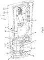
- Figure 2 which shows a first schematic perspective view of the image recording device 1 of Figure 1 , the second housing part 202 is not shown, so that the device 1 is partly cutaway.
- the device 1 furthermore comprises an optical element 3.
- the optical element 3 may be housed in the housing 200, in particular in the first housing part 2 and/or may be supported by the housing 200, in particular by the first housing part 2.
- the optical element 3 can, for example, be a camera or comprise a camera or can be part of a camera 9. In Figure 2 , in which the image recording device 1 is partly cutaway, the camera 9 is visible.
- Images or so-called recordings which are made with the aid of the camera 9 may, for example in the vehicle and/or on a part of the vehicle, be shown to the driver of the vehicle, for example with the aid of one or more electronic visual screens and/or with the aid of projection. It is greatly preferred for such images or recordings to be displayed to the driver of the vehicle without appreciable or noticeable delay.
- the optical element 3 is not visible. This is because the optical element 3 is temporarily screened off there, in this case by means of two screening caps 81, 82, which may be formed as eyelids, as it were. It is noted that the image recording device 1 in other embodiments can also be free of screening caps, or can have a different number of screening caps, such as, for example, a single screening cap.
- the optical element 3 can temporarily, for example when the optical element 3 does not need to be used, for example in a parked condition of the motor vehicle, be at least partly screened, for example to counteract unwanted dirt, precipitation, for example in the form of rain or snow, or anything else, ending up on the optical element 3.
- the screening cap or caps 81, 82 may, during use, be moved away from their protective position, as can be seen, for example, in Figure 3 , which shows a further schematic perspective view of the exemplary embodiment of the image recording device 1, in which the screening caps 81, 82 have cleared the optical element 3.
- the optical element 3 can comprise a sensor, in particular a light sensitive electronic sensor chip, such as a CCD or a CMOS, for scanning or recording images. Additionally, or alternatively, the optical element 3 can comprise at least one lens 32, or a lens system or lens assembly 33 with multiple lenses. Additionally or alternatively, the optical element 3 can comprise at least one at least partly transparent cap 30, in particular an at least partly transparent protection cap 30.
- the at least partly transparent protection cap 30 can be, for example, a vision-transmissive part of the housing, or can be, for example, a flat plate or transparent window, having an outwardly facing outer surface 31 which, for example, can form a substantially flat plane.
- the protection cap 30 may alternatively have, for example, a curved, preferably convex, outwardly facing outer surface 31, which, for example, may itself also do work as a lens.
- the at least partly transparent protection cap 30 can constitute a translucent protection or sealing and may, for example, be a part of glass or plastic.
- the at least partly transparent protection cap 30 can pass light from outside to a further part, located behind it, of the optical element 3, such as a lens, a lens assembly 33 or a light sensitive electronic sensor chip.
- the protection cap 30 may, for example, be located in front of a light sensitive electronic sensor chip, and/or may be located in front of one or more lenses 32, which lenses may then be located, for example, between the at least partly transparent protection cap 30 and the chip.
- optical element 3 can be a composite optical element 3 which may be composed of multiple parts, of which one or more parts per se could also constitute an optical element.
- the optical element 3, or a part thereof, in particular any at least partly transparent protection cap 30 for protecting other parts of a composite optical element 3, may be integrated in the housing part 2.
- the at least partly transparent protection cap 30 is a part of the camera 9.
- the optical element 3 has an outer surface 31.
- the outer surface 31 may, at any rate, for example, at least during use of the image recording device 1, be located on the outside of the image recording device 1 and may, for example during use, be exposed to dirt and/or weather influences, such as precipitation, for example in the form of rain or snow.
- the outer surface 31 of the optical element may be screened off, for example with the aid of the screening caps 81, 82.
- the outer surface 31 of the composite optical element 3 is formed by the at least partly transparent protection cap 30.
- the outer surface 31 may, for example, be formed by a lens, in particular a front lens.
- the part that forms the outer surface 31 of the optical element 3 can comprise a material that is relatively hard and/or relatively scratch-resistant, that is relatively antistatic, that is relatively hydrophobic, and/or that counteracts internal reflection relatively well.
- the outer surface 31 may be provided with a coating that is relatively hard, relatively scratch-resistant, relatively antistatic, and/or relatively hydrophobic, and/or counteracts internal reflection relatively well.
- the image recording device 1 may be provided with a cleaning device 5 having a cleaning part 51 for at least partly cleaning the outer surface 31 of the optical element 3.
- the cleaning device 5 is formed by a wiper 5 having a wiper part 51 for at least partly wiping the outer surface 31.
- Figure 3 which shows an assembly 7 of the image recording device 1 and an exemplary embodiment of the cleaning device 5, here formed by the wiper 5, the cleaning part 51, in particular the cleaning part 51 formed by a wiper part 51, more particularly the wiping edge 510 of the wiper part 51, is placed against the outer surface 31 of the optical element 3.
- the cleaning device 5, in particular the wiping edge 510 can be moved over the outer surface 31 to clean the outer surface 31.
- the cleaning device 5 in the example shown is formed as a wiper 5
- the cleaning part 51 of the cleaning device 5 in the example shown is formed as a wiper part 51
- the cleaning device 5 may in alternative embodiments be formed differently and/or be suitable for cleaning the outer surface 31 of the optical element 3 in a different manner than wiping.
- the cleaning part 51 while it could comprise, for example, a wiping part, could alternatively or additionally comprise or be, for example, a sprayer, a scraper, a brush and/or a sponge.
- cleaning device 5 is alternatively or additionally configured to clean by means of ultrasonic vibrations, and/or by local heating of the outer surface 31 of the optical element 3 and/or contamination such as moisture or dirt present thereon.
- the cleaning part 51 for example an edge thereof, such as, in the case of a wiper part, the wiping edge 510 thereof, may be so configured that it can conform to the outer surface 31 of the optical element 3 relatively well. If the outer surface 31, for example, is curved in a particular manner, then the edge, in particular the wiping edge 510 if present, may for example be provided with a corresponding concave curvature.
- the cleaning part 51 may, in embodiments, be provided with a slightly flexible, preferably slightly resiliently compressible, cleaning surface.
- the wiper part 51 and/or the wiping edge 510 thereof can comprise a rubber or elastomeric material or be made thereof.
- Figure 1 which shows a position of the image recording device 1 in which this device 1 is not in use to record images
- the screening caps 81, 82 are swung shut so that they temporarily screen off the optical element 3.
- the cleaning device 5, such as the wiper 5 can remain in contact with the outer surface 31 of the optical element 3, for example so that the cleaning device 5 does not need to be displaced in order to bring the screening cap or caps in a screening position, and the screening caps 81, 82 can preferably clamp the cleaning part 51, for example implemented as wiper part 51, for example as shown in Figures 1 and 2 .
- the screening caps 81, 82 may be moved clear, so that with the aid of the optical element 3 of the image recording device 1 images can be recorded.
- the wiper 5, or another cleaning device 5 is detachably mounted in the image recording device 1, and the image recording device 1 can therefore also be, temporarily, free of a cleaning device, for example after a worn and/or damaged cleaning device 5 has been removed and before a replacement cleaning device has been installed.
- the image recording device 1 of Figure 3 is also shown in Figure 4 , but unlike in Figure 3 , the wiper 5 in Figure 4 is detached from the image recording device 1. As a result, the wiper 5 is properly visible in Figure 4 .
- the wiper 5 additionally comprises, besides the wiper part 51, an engaging part 50 for cooperation with a driving part 4 of the image recording device 1, which driving part 4 is for driving the wiper 5 in order to have the wiper part 51 at least partly wipe the outer surface 31 of the optical element 3.
- the wiper 5 comprises two engaging parts 50, here formed by legs 500, which, for example at or near their end, may be provided with one or more hook parts 502. It is noted that the wiper 5 can also have a different number of engaging parts, for example a single engaging part or more than two engaging parts.
- the engaging parts 50 of the wiper 5 are formed by portions of a frame 59, in particular a metal frame 59, which supports the wiper part 51 and on which the wiper part is mounted, preferably rigidly mounted.
- the frame 59 may be manufactured from, for example, wire material.
- the wiper part 51 and the at least one engaging part can also be integrally formed.
- the driving part 4 is configured to cooperate with the engaging part 50 of the wiper 5. During use, the driving part 4 engages the engaging part 50 of the wiper 5, and this engaging part 50 of the wiper 5 in turn engages that driving part 4.
- the driving part 4 can, for example, at least partly lock or retain the engaging part 50, for example in a receiving channel 41 or feed-through channel 41 located in the driving part 4, so that the driving part 4 carries along the engaging part 50 when the driving part 4 is moved.
- the wiper part 51 can, during use, move substantially from the top down, for example to have gravity cooperate in discharging water or dirt, but alternatively the wiper part 51 may also move differently, for example, back and forth laterally.
- the driving part 4 is configured to translate, in particular to pivot back and forth about a pivoting axis 43, which reciprocating pivotal movement P is schematically represented in Figures 2 and 3 with the aid of arrow P.
- the pivoting axis 43 may for example be transverse to the optical axis 34 of the optical element 3.
- the pivoting axis 43 may for example extend substantially horizontally, for example in order to be able to wipe away, for example moisture, snow and/or dirt, in a substantially downward direction.
- the driving parts 4 which may, for example, be formed as two discs 44, are driven synchronously during wiping. So, here, during wiping, both driving parts 4 then move simultaneously in the same manner, for example by means of gear synchronization, for example with the aid of a single actuator, in particular a single electric motor 8.
- the driving part 4 can cause the wiper 5 to move in a different manner during use.
- the wiper part 51 can translate in a substantially flat plane, preferably it can move back and forth in said substantially flat plane, for example in a substantially rectilinear movement.
- the wiper part 51 can for example rotate such that it always wipes in the same direction over the outer surface 31 of the optical element 3 to be wiped, for example by turning around a rotation axis, which can be preferably substantially parallel to an optical axis 34 of the optical element 3.
- driving parts 4 While in the exemplary embodiment shown here two driving parts 4 are shown, alternative embodiments can have a different number of driving parts, such as, for example, one, three or four driving parts.
- An aspect of the presently disclosed image recording device 1 consists in the image recording device 1 being adjustable between a first condition in which the image recording device 1 allows at least partly introducing or taking out the engaging part 50 of the cleaning device 5 and a second condition in which the image recording device 1 prevents the engaging part 50 of the cleaning device 5 being taken out or introduced.
- the image recording device 1, at least, the parts shown thereof is in the first condition, while the image recording device 1, at least the parts shown thereof, in Figures 1 , 2 and 7 is in a second condition.
- the second condition which can be called a locking condition, in which the cleaning device 5, in principle, cannot be detached from the image recording device 1, can be a cleaning position, in particular a wiping position.
- the cleaning device 5 can be moved, but the device 1 does remain in the second condition in which the engaging part 50 (at any rate, at least one of the possibly multiple engaging parts 50) is locked. This can, for example, also prevent the cleaning device 5, for example formed by the wiper 5, from becoming detached unintendedly during wiping or other cleaning.
- the cleaning device 5 may, during cleaning, also move through a position, or possibly even multiple positions, in which the cleaning device 5 is not locked for just a moment.
- a position of the cleaning device 5 in which the cleaning device 5 is not locked may be chosen such that the cleaning device 5 needs to be moved from that position in a direction D50' upwards in order to detach it.
- the cleaning device 5 can be prevented from becoming detached unintendedly.
- the cleaning device 5 does not pass any position in which the cleaning device 5 is not substantially locked.
- the image recording device preferably does not enter the second condition during the cleaning, for example by wiping, of the outer surface 31 of the optical element 3.
- the image recording device 1 in its first condition does allow detaching of the wiper 5, or an alternative cleaning device.
- the image recording device 1 may for example be provided with a first passage 20 located in the housing part 2 and a second passage 40 located in the driving part 4, whereby in the first condition of the image recording device 1 the first passage 20 and the second passage 40 link up with each other and thus form a composite feed-through passage 60, as can be seen in Figures 4 and 5 .
- the composite feed-through channel 6 Through the composite feed-through channel 6, at least a portion of the engaging part 50 of the cleaning device 5 can be displaced such that this portion of the engaging part 50 is thereby simultaneously moved partly through the first passage 20 and partly through the second passage 40.
- the leg 500 of the engaging part may for example be slid partly through the first passage 20 and partly through the second passage 40, as can be seen, for example, in Figure 5
- the driving part 4 in the second condition prevents the respective engaging part 50 of a wiper being slid inside through the respective first passage 20, since in the second condition of the device 1 adjacent the first passage 20 there is no corresponding second passage in the driving part 4.
- the positioning of the driving part 4 relative to the housing part 2 can hence prevent the engaging part 50 of the cleaning device 5 being taken out or being introduced.
- the driving part 4 can, as shown in Figure 1 , at least partly close off an open side 22 of the first feed-through channel 21, which is represented by a dotted line 22 in Figure 5 .
- the first passage 20 and the second passage 40 can hence be displaced relative to each other with respect to the first condition of the image recording device 1, such that the first passage 20 and the second passage 40 no longer form the composite feed-through channel 60 that was still ample enough to displace at least a portion of the engaging part 50 of the cleaning device 5 partly through the first passage 20 and partly through the second passage 40 in the first condition.
- the mutually corresponding first passage 20 and second passage 40 can be brought in line with each other
- the image recording device 1 may for example be configured to adjust the driving part 4, for example with the aid of the electric motor 8 and a drive train cooperating therewith, and bring it in the first condition.
- the image recording device 1 may be configured to allow the driving part 4 to be manually moved to a position corresponding to the first condition.
- a lock or locking mechanism may be provided that has to be released first before the driving part 4, for example manually, can be adjusted such that the second passage 40 located therein can be brought in the position where this second passage 40 cooperates with the first passage 20 in the housing part 2.
- the image recording device 1, or a motor vehicle that is provided therewith is preferably so configured that the image recording device 1 in a parked position of the vehicle is in the second condition.
- the cleaning device 5, for example formed by the wiper cannot be taken out of the image recording device 1 without first moving and/or displacing the driving part 4 relative to the housing part 2.
- the second feed-through channel 41 which may be formed, for example, as a trench 41, can have an open side 42 which in the first condition of the image recording device 1 links up with an open side 22 of the first feed-through channel 21.
- the open side 22 or open edge 22 of the first feed-through channel 21 can be understood to mean that edge 22 or side 22 that in the second condition can abut against the driving part 4.
- This open side 22 of the first feed-through channel 21 and the open side 42 of the second feed-through channel 41 hence face each other in the first condition.
- both passages 20, 40 together can hence form the composite feed-through channel 60 which extends in a feed-in direction D50 or a take-out direction D50' of the engaging part 50, as can be seen, for example, in Figure 5 .
- the first passage 20 can substantially extend in the feed-in or take-out direction D50, D50'.
- the second passage 40 in the first condition of the image recording device 1, can substantially extend in a feed-in direction D50 or a take-out direction D50' of the engaging part 50 and the first feed-through channel 21 is in line with this feed-in direction D50 or take-out direction D50'.
- the feed-in direction D50 which corresponds to, but is opposite to, the take-out direction D50'
- the feed-in and take-out direction D50, D50' can also, in alternative embodiments, be curved, in particular, can follow a part of a circular arc.
- the leg, or each of the legs, 500 of the engaging part 50 may be so curved as to substantially correspond to the direction in which the respective composite feed-through channel 60 extends in the first condition.
- the second feed-through channel 41 which may be defined by the second passage 40 located in the driving part 4 can be open on at least one side 42 which extends substantially parallel to the feed-in direction D50 or take-out direction D50', which open side 42 is represented in Figure 5 by a dotted line 42.
- the second feed-through channel 41 can hence, for example, be formed at least partly as a trench 41.
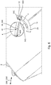
- Figures 5 and 6 show schematic perspective views of the housing part 2 and the driving part 4 in the first condition of the image recording device 1.
- the first passage 20 which is located in the housing part 2 in the example shown comprises three openings 20A, 20B, 20C in three wall parts of the housing part 2.
- these openings 20A, 20B, 20C are in line with the second passage 40 formed by the second feed-through channel 41.
- the engaging part 50 including the associated hook part 502 can be inserted in the first openings 20A and the second feed-through channel 41 cooperating therewith in the first condition.
- the engaging part 50 can be slid further inside, whereby it can be moved on further through the second feed-through channel 41 and the hook part 502 can be slid for example through the first passage 20, in particular, for example, through further openings 20B, 20C in wall parts of the housing part 2.
- the cleaning device 5 cannot be detached in the second condition of the image recording device 1, at least, not without causing considerable damage.
- the intention is not for the cleaning device 5 to prevent the driving part 4 from being displaced in order to bring the device 1 in the first condition.
- the engaging part 50 may be configured such that when it has been introduced, the leg 500 thereof is not in the first passage 20 but preferably merely in the second passage 40.
- the hook part 502 is still in the first passage 20 and/or in line with the first passage 20, when the engaging part 50 has been introduced far enough.
- the leg When the driving part 4 is then moved, the leg can hence move along, since the leg 500 is not in the first passage 20, but in the second passage 40 located in the driving part 4 itself.
- the hook part 53 can thereby be brought out of the line of the first passage 20 and/or out of the produced part of the first passage 20, as has been done in Figure 7 .
- the housing part 2 should offer room to the hook part 53 of the engaging part 50 of which the leg 500 moves along and/or displaces along with the moving and/or displacing driving part 4.
- the housing part 2 is provided to that end with a channel 24 which can house the hook part 53 in the second condition of the image recording device 1.
- the driving part 4 during cleaning rotates about the earlier-mentioned pivoting axis 43.
- the channel 24 here extends along a part of a circular arc around the pivoting axis 43.
- such a channel 24 may extend differently in other embodiments.
- the channel 24 can extend, for example, in a straight line in the case where the driving part 4 during cleaning moves in a straight line relative to the housing part 2.
- the image recording device 1, more preferably its housing part 2 may be provided with a first stop surface 11 for, in the second condition of the image recording device 1, cooperating with a stop surface 503 of a hook part 502 of the engaging part 50.
- the first stop surface 11 can, in cooperation with the stop surface 503 of the hook part 502, for example prevent the engaging part 50 from moving out unintendedly.
- a malevolent person be prevented from pulling the cleaning device 5 out of the image recording device 1, for example to make mischief or to steal it, but what can also be prevented is that the contact between the cleaning part 51 and the outer surface 31 of the optical element 3 to be wiped or cleaned otherwise is temporarily or permanently broken or gets too weak to bring about a proper cleaning any longer.
- the engagement of the stop surface 503 of the hook part 502 with the first stop surface 11 can thus provide for a desired pre-tension or bias by which the cleaning part 51 is pressed against the outer surface 31 to be cleaned.
- a contact between the stop surface 503 of the hook part 502 and the first stop surface 11 can preferably form substantially a line contact or a point contact.
- at least the stop surface 503 of the hook part 502 may be formed by a spherical surface.
- the engaging part 50 can comprise a substantially elongated part 500, such as a leg 500, which in the first condition can extend substantially in the feed-in direction D50 or take-out direction D50' of the engaging part 50 of the cleaning device 5, by contrast, the hook part 502, at least a stop surface 503 formed by the hook part 502, can extend in a direction D503 which (also) in the first condition deviates from the feed-in and/or take-out direction D50, D50' of the engaging part 50.
- the direction D503 in which the stop surface 503 of the hook part 502 extends can be substantially transverse to the length direction of the leg 500 of the engaging part, and/or the direction D503 of the stop surface in the first condition can be substantially transverse to the feed-in direction D50 or take-out direction D50'.
- a free space 14 may be provided for having the hook part 502 move during movement of the cleaning device 5.
- the free space 14 may for example be formed by a channel 24 which can house the hook part 502 in the second condition of the image recording device 1.
- the image recording device 1, in particular the housing part 2 thereof, can comprise a further stop surface 12 which is intended to obviate the engaging part 50 being inserted into the image recording device 1 too far. This may for example prevent the cleaning part 51 being pressed against the outer surface 31 of the optical element 3 too hard. Damages to the cleaning part 51 and/or the outer surface 31 can thus for example be counteracted.
- the further stop surface 12 may for example be formed by a second wall of the channel 24 which can house the hook part 502 in the second condition of the image recording device 1.
- an alternative cleaning device may be used.
- Such an alternative cleaning device can be, for example, a scrubbing device, a scraping device, a spraying device or any other cleaning device.
- the alternative cleaning device can comprise a cleaning part which is, for example, provided with a sprayer, a scraper, a sponge, a brush, a heating element, and/or an element for at least partly cleaning the outer surface of the optical element by means of ultrasonic vibrations.
- a wiper part can be used as an alternative when in the present disclosure mention is made of a wiper part.
- the driver of the motor vehicle can be a human, in particular a human who is present in the motor vehicle, the vehicle could also be drivable, for example, with the aid of artificial intelligence, and the motor vehicle could be, for example, a self-driving car.
- the artificial intelligence should also have, for example, sufficient view of the surroundings of the motor vehicle.
Landscapes
- Engineering & Computer Science (AREA)
- Mechanical Engineering (AREA)
- Physics & Mathematics (AREA)
- General Physics & Mathematics (AREA)
- Optics & Photonics (AREA)
- Studio Devices (AREA)
- Ink Jet (AREA)
- Camera Bodies And Camera Details Or Accessories (AREA)
- Accessory Devices And Overall Control Thereof (AREA)
Description
- The invention relates to an image recording device for a body of a motor vehicle, wherein the image recording device comprises an optical element.
- Image recording devices of this type are known and are used, for example, in cars, but also in other motor vehicles. The optical element of the image recording device can be or comprise a camera or a part of a camera. The image recording device may be configured to offer vision to a driver of the motor vehicle vision, preferably vision of an area located next to or behind the vehicle.
- For example, the image recording device may be configured to offer a driver vision along a flank of the vehicle, of an area next to the driver and/or next to the vehicle and/or behind the vehicle. The image recording device may for example be configured and/or be intended for replacement and/or for support of an exterior mirror or so-called wing mirror of a car or other motor vehicle.
- Alternatively or additionally, the image recording device may be for a different purpose, for example, for eliminating a blind spot of an exterior mirror, so that a driver of a motor vehicle can be offered a relatively good view of an area that would not be (well) visible in a conventional exterior mirror of a vehicle, such as, for example, the area next to the driver. This may for example prevent a driver overlooking a vehicle overtaking him when he wants to change lane and then, for example, fails to look over his shoulder properly.
- The image recording device may alternatively or additionally be configured and/or intended for assistance in parking. The image recording device may for example constitute a so-called backing camera, which can record a relatively large part or even the complete blind spot behind the motor vehicle, which can thereupon, preferably without appreciable or noticeable delay, be displayed to the driver of the vehicle. For example in the case where the image recording device constitutes a backing camera, the image recording device may, for example, be merely temporarily activated, for example when the vehicle backs up or when the gearbox of the vehicle is in reverse gear.
- It is noted that the image recording device for the motor vehicle may also, additionally or alternatively, be intended for other purposes and/or be configured therefor.
- In order to prevent the image recording device being at least temporarily unintendedly unable to record a proper image, as a result of which the driver of the motor vehicle, at least temporarily, could not be offered a proper view of a particular situation near the vehicle, a situation should be prevented where the outer surface of the optical element of the image recording device is unintendedly at least temporarily not free of water drops, snow, dirt and/or the like. In particular in the case where the image recording device is intended and/or configured to offer vision of an area that is not or hardly visible to the driver in any other manner, it is desirable that it can be promoted, or can even be guaranteed, that the outer surface of the optical element is clean or can be rendered clean. This can be of particular importance, for example in the case where the image recording device replaces an exterior mirror and there is no traditional exterior mirror present that could serve as a backup if the image recording device is at least temporarily not usable, for example due to the outer surface of the optical element thereof being at least temporarily not clean enough.
- Document
DE 10 2004 220 257 A1 discloses an image recording device of a motor vehicle according to the preamble of claim 1. - The disclosure therefore envisages providing an alternative image recording device for a motor vehicle and/or an alternative motor vehicle with an image recording device. Envisaged in particular is the provision of an image recording device for a motor vehicle and/or a motor vehicle with an image recording device, whereby a condition can be promoted where an outer surface of an optical element of the image recording device is clean enough to be able to record a relatively good image, preferably for display to a driver of the vehicle. Still more particularly, the present disclosure envisages counteracting any condition where, at least temporarily, it cannot be ensured, or cannot be ensured well enough, that the outer surface is clean enough, can be rendered clean enough and/or can be kept clean enough.
- The present disclosure provides to that end an image recording device for a body of a motor vehicle, comprising a housing part, an optical element having an outer surface, and a driving part for engaging an engaging part of a movable cleaning device, for example a wiper, which movable cleaning device furthermore comprises a cleaning part, for example a wiper part, for at least partly cleaning, for example at least partly wiping, the outer surface, wherein the driving part is furthermore for driving the movable cleaning device in order to have the cleaning part at least partly clean the outer surface of the optical element, and wherein the image recording device is adjustable between a first condition in which the image recording device allows at least partly introducing or taking out the engaging part of the movable cleaning device and a second condition in which the image recording device prevents the engaging part of the movable cleaning device being taken out or being introduced.
- The image recording device is configured as to be adjustable between a first condition in which the image recording device releases the engaging part of the movable cleaning device and thus allows at least partly introducing or taking out the engaging part of the movable cleaning device and a second condition in which the image recording device blocks the engaging part of the movable cleaning device and thus prevents the engaging part of the movable cleaning device being taken out or being introduced.
- With the aid of the cleaning device, for example the wiper, the outer surface can be cleaned and/or kept clean. By configuring the image recording device such that it is adjustable between a first condition in which the image recording device allows at least partly introducing or taking out the engaging part of the movable cleaning device and a second condition in which the image recording device prevents the engaging part of the cleaning device being taken out or being introduced, this can on the one hand prevent the cleaning device being purloined, for example by a vandal or thief, while on the other hand it can also be ensured that a worn and/or damaged cleaning device can be replaced relatively simply. This promotes a condition where at all times a relatively well working cleaning device, for example a relatively well cleaning wiper, can be present, since it is made possible for a cleaning device not functioning properly to be replaced relatively simply and, what is more, in addition, this counteracts a cleaning device disappearing unintendedly, for example when the vehicle is parked. Accordingly, this can for example prevent the cleaning device, for example the wiper, not being present anymore when a driver, for example, is about to leave in a vehicle which has been parked for some time. Also, this can counteract the image recording device unintendedly at least temporarily not functioning well or not well enough.
- The image recording device according to this aspect of the present disclosure can hence relatively well prevent a situation where it can temporarily not be ensured, or not be ensured well enough, that the outer surface of the optical element is clean enough, can be rendered clean enough and/or can be kept clean enough, for example to offer a driver of the motor vehicle a relatively good view of a particular part of the surroundings of the motor vehicle. This can for example obviate the driver participating in traffic with a relatively unsafe vehicle.
- In a preferred embodiment according to an aspect of the disclosure, the image recording device is so configured that in the second condition of the image recording device, the positioning of the driving part relative to the housing part prevents the engaging part of the cleaning device being taken out or being introduced. Thus, with the aid of a drive for the cleaning device, it can not only be arranged that the cleaning device can be driven to clean the optical element, but also, with the aid of that same drive, the image recording device can be brought in a locking condition in which the cleaning device is locked and whereby, for example, theft of the cleaning device can then be prevented.
- By using a same driving part for both the cleaning, in particular wiping, of the optical element and also for the locking of the cleaning device, in particular the wiper, such an aspect of the present disclosure can contribute in a relatively elegant, relatively simple and/or relatively cost-efficient manner to a relatively safe image recording device for a motor vehicle.
- The present disclosure furthermore relates to a cleaning device, in particular a wiper, for an image recording device according to an aspect of this disclosure. The cleaning device, which may for example be intended to replace a damaged and/or worn cleaning device, may be configured to cooperate with the image recording device.
- Also, the disclosure relates to an assembly comprising an image recording device and a corresponding cleaning device, in particular a wiper.
- Further, the disclosure relates to a motor vehicle provided with at least one image recording device and/or at least one assembly including an image recording device and a corresponding cleaning device, in particular a wiper.
- Further advantageous embodiments of the disclosure are represented in the subclaims and described in the description below.
- The invention will be further elucidated on the basis of an exemplary embodiment represented in the drawing. In the drawing:
-
Figure 1 shows a schematic perspective view of an exemplary embodiment of an image recording device, with this image recording device provided with a cleaning device in the form of a wiper; -
Figure 2 shows a further schematic perspective view of the image recording device ofFigure 1 , with this device being partly cutaway; -
Figure 3 shows a further schematic perspective view of a detail of the image recording device ofFigures 1 and2 in a use condition; -
Figure 4 shows a further schematic perspective view of the detail of the image recording device shown inFigure 3 , with the wiper detached from the image recording device; -
Figure 5 shows a schematic perspective view of a detail of a housing part and a driving part of the image recording device ofFigures 1-4 ; -
Figure 6 shows a further schematic perspective view of the housing part and driving part shown inFigure 5 , with a cleaning device in the form of a wiper installed; and -
Figure 7 shows a yet further schematic perspective view of the housing part ofFigures 5 and6 , with the driving part and the wiper in a different position than inFigure 6 . - The drawing shows only schematic views of a preferred embodiment of the disclosure. In the figures, like or corresponding parts are designated with the same or corresponding reference numerals.
-
Figure 1 shows a schematic perspective view of an image recording device 1. The device 1 may for example be intended to offer a driver of the vehicle vision of a part of the surroundings of the motor vehicle that would otherwise be poorly visible or not visible to the driver. The device 1 may for example be configured and/or be intended for replacement or for support of an exterior mirror or wing mirror for a motor vehicle, and may for example be for displaying at least a part of a blind spot. - The image recording device 1 comprises a
housing part 2. Thehousing part 2 may for example constitute a part of ahousing 200 and/or carryingarm 200 which, for example on the side of the body, may be mounted to the body of the vehicle, for example to a door of the vehicle. It is noted that thehousing 200 and/or carryingarm 200 does not need to be rigidly connected to the body, but, for example, may be at least partly collapsible, adapted to be folded (in) and/or slid (in). - In the example shown here, the
housing part 2 is a loose part, which is also shown, for example, inFigure 5 . Alternatively, however, thehousing part 2 may also be integrated in thehousing 200 and/or thecarrying arm 200. - In the exemplary embodiment shown here in
Figure 1 , thecarrying arm 200 comprises twofurther housing parts first housing part 2 in the assembled condition of the image recording device 1. InFigure 2 , which shows a first schematic perspective view of the image recording device 1 ofFigure 1 , thesecond housing part 202 is not shown, so that the device 1 is partly cutaway. - The device 1 furthermore comprises an
optical element 3. Theoptical element 3 may be housed in thehousing 200, in particular in thefirst housing part 2 and/or may be supported by thehousing 200, in particular by thefirst housing part 2. Theoptical element 3 can, for example, be a camera or comprise a camera or can be part of acamera 9. InFigure 2 , in which the image recording device 1 is partly cutaway, thecamera 9 is visible. - Images or so-called recordings which are made with the aid of the
camera 9 may, for example in the vehicle and/or on a part of the vehicle, be shown to the driver of the vehicle, for example with the aid of one or more electronic visual screens and/or with the aid of projection. It is greatly preferred for such images or recordings to be displayed to the driver of the vehicle without appreciable or noticeable delay. - In
Figure 1 theoptical element 3 is not visible. This is because theoptical element 3 is temporarily screened off there, in this case by means of twoscreening caps - By the screening cap or caps 81, 82, the
optical element 3 can temporarily, for example when theoptical element 3 does not need to be used, for example in a parked condition of the motor vehicle, be at least partly screened, for example to counteract unwanted dirt, precipitation, for example in the form of rain or snow, or anything else, ending up on theoptical element 3. The screening cap or caps 81, 82 may, during use, be moved away from their protective position, as can be seen, for example, inFigure 3 , which shows a further schematic perspective view of the exemplary embodiment of the image recording device 1, in which the screening caps 81, 82 have cleared theoptical element 3. - The
optical element 3 can comprise a sensor, in particular a light sensitive electronic sensor chip, such as a CCD or a CMOS, for scanning or recording images. Additionally, or alternatively, theoptical element 3 can comprise at least one lens 32, or a lens system or lens assembly 33 with multiple lenses. Additionally or alternatively, theoptical element 3 can comprise at least one at least partlytransparent cap 30, in particular an at least partlytransparent protection cap 30. The at least partlytransparent protection cap 30 can be, for example, a vision-transmissive part of the housing, or can be, for example, a flat plate or transparent window, having an outwardly facingouter surface 31 which, for example, can form a substantially flat plane. Also, however, theprotection cap 30 may alternatively have, for example, a curved, preferably convex, outwardly facingouter surface 31, which, for example, may itself also do work as a lens. The at least partlytransparent protection cap 30 can constitute a translucent protection or sealing and may, for example, be a part of glass or plastic. - During use, the at least partly
transparent protection cap 30 can pass light from outside to a further part, located behind it, of theoptical element 3, such as a lens, a lens assembly 33 or a light sensitive electronic sensor chip. Theprotection cap 30 may, for example, be located in front of a light sensitive electronic sensor chip, and/or may be located in front of one or more lenses 32, which lenses may then be located, for example, between the at least partlytransparent protection cap 30 and the chip. - It is noted that in this description the
optical element 3 can be a compositeoptical element 3 which may be composed of multiple parts, of which one or more parts per se could also constitute an optical element. - Furthermore, it is noted that the
optical element 3, or a part thereof, in particular any at least partlytransparent protection cap 30 for protecting other parts of a compositeoptical element 3, may be integrated in thehousing part 2. In the example shown, the at least partlytransparent protection cap 30 is a part of thecamera 9. - The
optical element 3 has anouter surface 31. Theouter surface 31 may, at any rate, for example, at least during use of the image recording device 1, be located on the outside of the image recording device 1 and may, for example during use, be exposed to dirt and/or weather influences, such as precipitation, for example in the form of rain or snow. When theoptical element 3 does not need to be used, for example when the vehicle is parked, theouter surface 31 of the optical element may be screened off, for example with the aid of the screening caps 81, 82. In the exemplary embodiment shown, theouter surface 31 of the compositeoptical element 3 is formed by the at least partlytransparent protection cap 30. In alternative embodiments, theouter surface 31 may, for example, be formed by a lens, in particular a front lens. - The part that forms the
outer surface 31 of theoptical element 3 can comprise a material that is relatively hard and/or relatively scratch-resistant, that is relatively antistatic, that is relatively hydrophobic, and/or that counteracts internal reflection relatively well. Alternatively or additionally, theouter surface 31 may be provided with a coating that is relatively hard, relatively scratch-resistant, relatively antistatic, and/or relatively hydrophobic, and/or counteracts internal reflection relatively well. - The image recording device 1 may be provided with a
cleaning device 5 having a cleaningpart 51 for at least partly cleaning theouter surface 31 of theoptical element 3. - In the present exemplary embodiment, the
cleaning device 5 is formed by awiper 5 having awiper part 51 for at least partly wiping theouter surface 31. InFigure 3 , which shows anassembly 7 of the image recording device 1 and an exemplary embodiment of thecleaning device 5, here formed by thewiper 5, the cleaningpart 51, in particular the cleaningpart 51 formed by awiper part 51, more particularly the wipingedge 510 of thewiper part 51, is placed against theouter surface 31 of theoptical element 3. During use of thecleaning device 5, thecleaning device 5, in particular the wipingedge 510, can be moved over theouter surface 31 to clean theouter surface 31. - While the
cleaning device 5 in the example shown is formed as awiper 5, and the cleaningpart 51 of thecleaning device 5 in the example shown is formed as awiper part 51, thecleaning device 5 may in alternative embodiments be formed differently and/or be suitable for cleaning theouter surface 31 of theoptical element 3 in a different manner than wiping. The cleaningpart 51, while it could comprise, for example, a wiping part, could alternatively or additionally comprise or be, for example, a sprayer, a scraper, a brush and/or a sponge. Also, it is conceivable thatcleaning device 5 is alternatively or additionally configured to clean by means of ultrasonic vibrations, and/or by local heating of theouter surface 31 of theoptical element 3 and/or contamination such as moisture or dirt present thereon. - It is noted that the cleaning
part 51, for example an edge thereof, such as, in the case of a wiper part, the wipingedge 510 thereof, may be so configured that it can conform to theouter surface 31 of theoptical element 3 relatively well. If theouter surface 31, for example, is curved in a particular manner, then the edge, in particular the wipingedge 510 if present, may for example be provided with a corresponding concave curvature. - Additionally or alternatively, the cleaning
part 51, or at least theedge 510 thereof, may, in embodiments, be provided with a slightly flexible, preferably slightly resiliently compressible, cleaning surface. - For example, the
wiper part 51 and/or the wipingedge 510 thereof can comprise a rubber or elastomeric material or be made thereof. - In
Figure 1 , which shows a position of the image recording device 1 in which this device 1 is not in use to record images, the screening caps 81, 82 are swung shut so that they temporarily screen off theoptical element 3. In embodiments, in such a rest position, thecleaning device 5, such as thewiper 5, can remain in contact with theouter surface 31 of theoptical element 3, for example so that thecleaning device 5 does not need to be displaced in order to bring the screening cap or caps in a screening position, and the screening caps 81, 82 can preferably clamp thecleaning part 51, for example implemented aswiper part 51, for example as shown inFigures 1 and2 . In a use position, such as shown, for example, inFigure 3 , the screening caps 81, 82 may be moved clear, so that with the aid of theoptical element 3 of the image recording device 1 images can be recorded. - The
wiper 5, or anothercleaning device 5, is detachably mounted in the image recording device 1, and the image recording device 1 can therefore also be, temporarily, free of a cleaning device, for example after a worn and/or damagedcleaning device 5 has been removed and before a replacement cleaning device has been installed. The image recording device 1 ofFigure 3 is also shown inFigure 4 , but unlike inFigure 3 , thewiper 5 inFigure 4 is detached from the image recording device 1. As a result, thewiper 5 is properly visible inFigure 4 . - As can be properly seen in
Figure 4 , thewiper 5 additionally comprises, besides thewiper part 51, an engagingpart 50 for cooperation with a drivingpart 4 of the image recording device 1, which drivingpart 4 is for driving thewiper 5 in order to have thewiper part 51 at least partly wipe theouter surface 31 of theoptical element 3. In the exemplary embodiment shown inFigure 4 , thewiper 5 comprises two engagingparts 50, here formed bylegs 500, which, for example at or near their end, may be provided with one ormore hook parts 502. It is noted that thewiper 5 can also have a different number of engaging parts, for example a single engaging part or more than two engaging parts. - In the exemplary embodiment shown, the engaging
parts 50 of thewiper 5 are formed by portions of aframe 59, in particular ametal frame 59, which supports thewiper part 51 and on which the wiper part is mounted, preferably rigidly mounted. Theframe 59 may be manufactured from, for example, wire material. Alternatively, thewiper part 51 and the at least one engaging part can also be integrally formed. - The driving
part 4 is configured to cooperate with the engagingpart 50 of thewiper 5. During use, the drivingpart 4 engages the engagingpart 50 of thewiper 5, and this engagingpart 50 of thewiper 5 in turn engages that drivingpart 4. The drivingpart 4 can, for example, at least partly lock or retain theengaging part 50, for example in a receivingchannel 41 or feed-throughchannel 41 located in the drivingpart 4, so that the drivingpart 4 carries along the engagingpart 50 when the drivingpart 4 is moved. - Preferably, the
wiper part 51 can, during use, move substantially from the top down, for example to have gravity cooperate in discharging water or dirt, but alternatively thewiper part 51 may also move differently, for example, back and forth laterally. - In the exemplary embodiment shown, the driving
part 4 is configured to translate, in particular to pivot back and forth about a pivotingaxis 43, which reciprocating pivotal movement P is schematically represented inFigures 2 and3 with the aid of arrow P. In preferred embodiments, the pivotingaxis 43 may for example be transverse to theoptical axis 34 of theoptical element 3. Additionally, or alternatively, the pivotingaxis 43 may for example extend substantially horizontally, for example in order to be able to wipe away, for example moisture, snow and/or dirt, in a substantially downward direction. - In the exemplary embodiment shown, the driving
parts 4, which may, for example, be formed as two discs 44, are driven synchronously during wiping. So, here, during wiping, both drivingparts 4 then move simultaneously in the same manner, for example by means of gear synchronization, for example with the aid of a single actuator, in particular a singleelectric motor 8. - However, in alternative embodiments the driving
part 4 can cause thewiper 5 to move in a different manner during use. For example, thewiper part 51 can translate in a substantially flat plane, preferably it can move back and forth in said substantially flat plane, for example in a substantially rectilinear movement. Alternatively, thewiper part 51 can for example rotate such that it always wipes in the same direction over theouter surface 31 of theoptical element 3 to be wiped, for example by turning around a rotation axis, which can be preferably substantially parallel to anoptical axis 34 of theoptical element 3. - While in the exemplary embodiment shown here two driving
parts 4 are shown, alternative embodiments can have a different number of driving parts, such as, for example, one, three or four driving parts. - An aspect of the presently disclosed image recording device 1 consists in the image recording device 1 being adjustable between a first condition in which the image recording device 1 allows at least partly introducing or taking out the engaging
part 50 of thecleaning device 5 and a second condition in which the image recording device 1 prevents the engagingpart 50 of thecleaning device 5 being taken out or introduced. InFigures 3-6 , the image recording device 1, at least, the parts shown thereof, is in the first condition, while the image recording device 1, at least the parts shown thereof, inFigures 1 ,2 and7 is in a second condition. The second condition, which can be called a locking condition, in which thecleaning device 5, in principle, cannot be detached from the image recording device 1, can be a cleaning position, in particular a wiping position. In this cleaning position thecleaning device 5 can be moved, but the device 1 does remain in the second condition in which the engaging part 50 (at any rate, at least one of the possibly multiple engaging parts 50) is locked. This can, for example, also prevent thecleaning device 5, for example formed by thewiper 5, from becoming detached unintendedly during wiping or other cleaning. - Alternatively, the
cleaning device 5 may, during cleaning, also move through a position, or possibly even multiple positions, in which thecleaning device 5 is not locked for just a moment. For example to prevent thecleaning device 5 then falling out of the image recording device 1, such a position of thecleaning device 5 in which thecleaning device 5 is not locked may be chosen such that thecleaning device 5 needs to be moved from that position in a direction D50' upwards in order to detach it. Thus, thecleaning device 5 can be prevented from becoming detached unintendedly. - Preferably, however, during cleaning, the
cleaning device 5 does not pass any position in which thecleaning device 5 is not substantially locked. In other words, the image recording device preferably does not enter the second condition during the cleaning, for example by wiping, of theouter surface 31 of theoptical element 3. - In contrast with the locking in the second condition, the image recording device 1 in its first condition does allow detaching of the
wiper 5, or an alternative cleaning device. To this end, the image recording device 1 may for example be provided with a first passage 20 located in thehousing part 2 and asecond passage 40 located in the drivingpart 4, whereby in the first condition of the image recording device 1 the first passage 20 and thesecond passage 40 link up with each other and thus form a composite feed-throughpassage 60, as can be seen inFigures 4 and5 . Through the composite feed-through channel 6, at least a portion of theengaging part 50 of thecleaning device 5 can be displaced such that this portion of theengaging part 50 is thereby simultaneously moved partly through the first passage 20 and partly through thesecond passage 40. Thus, in the first condition of the image recording device 1 theleg 500 of the engaging part may for example be slid partly through the first passage 20 and partly through thesecond passage 40, as can be seen, for example, inFigure 5 , whereas the drivingpart 4 in the second condition, as can be seen, for example, inFigure 1 , prevents the respective engagingpart 50 of a wiper being slid inside through the respective first passage 20, since in the second condition of the device 1 adjacent the first passage 20 there is no corresponding second passage in the drivingpart 4. In the second condition of the image recording device 1, for example, the positioning of the drivingpart 4 relative to thehousing part 2 can hence prevent theengaging part 50 of thecleaning device 5 being taken out or being introduced. In the second condition, the drivingpart 4 can, as shown inFigure 1 , at least partly close off anopen side 22 of the first feed-through channel 21, which is represented by a dottedline 22 inFigure 5 . - To this end, in the second condition of the image recording device 1, the first passage 20 and the
second passage 40 can hence be displaced relative to each other with respect to the first condition of the image recording device 1, such that the first passage 20 and thesecond passage 40 no longer form the composite feed-throughchannel 60 that was still ample enough to displace at least a portion of theengaging part 50 of thecleaning device 5 partly through the first passage 20 and partly through thesecond passage 40 in the first condition. - In order to bring the image recording device 1 from the second condition into the first condition, in which the
cleaning device 5 can be installed in the image recording device 1, the mutually corresponding first passage 20 andsecond passage 40 can be brought in line with each other The image recording device 1 may for example be configured to adjust the drivingpart 4, for example with the aid of theelectric motor 8 and a drive train cooperating therewith, and bring it in the first condition. Alternatively or additionally, the image recording device 1 may be configured to allow the drivingpart 4 to be manually moved to a position corresponding to the first condition. For example to counteract a malevolent person bringing the drivingpart 4 in such a position in which thecleaning device 5 can be detached, a lock or locking mechanism may be provided that has to be released first before the drivingpart 4, for example manually, can be adjusted such that thesecond passage 40 located therein can be brought in the position where thissecond passage 40 cooperates with the first passage 20 in thehousing part 2. - It is noted that the image recording device 1, or a motor vehicle that is provided therewith, is preferably so configured that the image recording device 1 in a parked position of the vehicle is in the second condition. This is to say that when the vehicle, for example a car, is parked, the
cleaning device 5, for example formed by the wiper, cannot be taken out of the image recording device 1 without first moving and/or displacing the drivingpart 4 relative to thehousing part 2. - The second feed-through
channel 41, which may be formed, for example, as atrench 41, can have anopen side 42 which in the first condition of the image recording device 1 links up with anopen side 22 of the first feed-through channel 21. It is noted here that theopen side 22 oropen edge 22 of the first feed-through channel 21 can be understood to mean thatedge 22 orside 22 that in the second condition can abut against the drivingpart 4. Thisopen side 22 of the first feed-through channel 21 and theopen side 42 of the second feed-throughchannel 41 hence face each other in the first condition. - In the first condition, both
passages 20, 40 together can hence form the composite feed-throughchannel 60 which extends in a feed-in direction D50 or a take-out direction D50' of theengaging part 50, as can be seen, for example, inFigure 5 . In the first condition of the image recording device 1, the first passage 20 can substantially extend in the feed-in or take-out direction D50, D50'. - In embodiments, in the first condition of the image recording device 1, the
second passage 40 can substantially extend in a feed-in direction D50 or a take-out direction D50' of theengaging part 50 and the first feed-through channel 21 is in line with this feed-in direction D50 or take-out direction D50'. It is noted that while the feed-in direction D50, which corresponds to, but is opposite to, the take-out direction D50', can extend substantially in a straight line, as is the case here, the feed-in and take-out direction D50, D50' can also, in alternative embodiments, be curved, in particular, can follow a part of a circular arc. The leg, or each of the legs, 500 of theengaging part 50 may be so curved as to substantially correspond to the direction in which the respective composite feed-throughchannel 60 extends in the first condition. - The second feed-through
channel 41 which may be defined by thesecond passage 40 located in the drivingpart 4 can be open on at least oneside 42 which extends substantially parallel to the feed-in direction D50 or take-out direction D50', whichopen side 42 is represented inFigure 5 by a dottedline 42. The second feed-throughchannel 41 can hence, for example, be formed at least partly as atrench 41. -
Figures 5 and6 show schematic perspective views of thehousing part 2 and the drivingpart 4 in the first condition of the image recording device 1. FromFigure 5 it can be derived that the first passage 20 which is located in thehousing part 2 in the example shown comprises threeopenings housing part 2. In the first condition of the image recording device 1 theseopenings second passage 40 formed by the second feed-throughchannel 41. In order to install thewiper 5, the engagingpart 50 including the associatedhook part 502 can be inserted in the first openings 20A and the second feed-throughchannel 41 cooperating therewith in the first condition. Thereupon, the engagingpart 50 can be slid further inside, whereby it can be moved on further through the second feed-throughchannel 41 and thehook part 502 can be slid for example through the first passage 20, in particular, for example, throughfurther openings housing part 2. - As mentioned hereinabove, the
cleaning device 5 cannot be detached in the second condition of the image recording device 1, at least, not without causing considerable damage. On the other hand, of course, the intention is not for thecleaning device 5 to prevent the drivingpart 4 from being displaced in order to bring the device 1 in the first condition. To this end, the engagingpart 50 may be configured such that when it has been introduced, theleg 500 thereof is not in the first passage 20 but preferably merely in thesecond passage 40. Preferably, merely thehook part 502 is still in the first passage 20 and/or in line with the first passage 20, when the engagingpart 50 has been introduced far enough. When the drivingpart 4 is then moved, the leg can hence move along, since theleg 500 is not in the first passage 20, but in thesecond passage 40 located in the drivingpart 4 itself. Through movement or displacement of the drivingpart 4 relative to thehousing part 2, the hook part 53 can thereby be brought out of the line of the first passage 20 and/or out of the produced part of the first passage 20, as has been done inFigure 7 . In order to make this possible, thehousing part 2 should offer room to the hook part 53 of theengaging part 50 of which theleg 500 moves along and/or displaces along with the moving and/or displacing drivingpart 4. In the example shown, thehousing part 2 is provided to that end with achannel 24 which can house the hook part 53 in the second condition of the image recording device 1. In the example shown, the drivingpart 4 during cleaning, for example by wiping, rotates about the earlier-mentionedpivoting axis 43. Hence, thechannel 24 here extends along a part of a circular arc around the pivotingaxis 43. However, such achannel 24 may extend differently in other embodiments. Thus, thechannel 24 can extend, for example, in a straight line in the case where the drivingpart 4 during cleaning moves in a straight line relative to thehousing part 2. - Preferably, the image recording device 1, more preferably its
housing part 2, may be provided with afirst stop surface 11 for, in the second condition of the image recording device 1, cooperating with astop surface 503 of ahook part 502 of theengaging part 50. Thefirst stop surface 11 can, in cooperation with thestop surface 503 of thehook part 502, for example prevent theengaging part 50 from moving out unintendedly. As a result, not only can a malevolent person be prevented from pulling thecleaning device 5 out of the image recording device 1, for example to make mischief or to steal it, but what can also be prevented is that the contact between the cleaningpart 51 and theouter surface 31 of theoptical element 3 to be wiped or cleaned otherwise is temporarily or permanently broken or gets too weak to bring about a proper cleaning any longer. The engagement of thestop surface 503 of thehook part 502 with thefirst stop surface 11 can thus provide for a desired pre-tension or bias by which thecleaning part 51 is pressed against theouter surface 31 to be cleaned. For example to limit friction, a contact between thestop surface 503 of thehook part 502 and thefirst stop surface 11 can preferably form substantially a line contact or a point contact. For example, at least thestop surface 503 of thehook part 502 may be formed by a spherical surface. - Whilst the engaging
part 50 can comprise a substantiallyelongated part 500, such as aleg 500, which in the first condition can extend substantially in the feed-in direction D50 or take-out direction D50' of theengaging part 50 of thecleaning device 5, by contrast, thehook part 502, at least astop surface 503 formed by thehook part 502, can extend in a direction D503 which (also) in the first condition deviates from the feed-in and/or take-out direction D50, D50' of theengaging part 50. Preferably, the direction D503 in which thestop surface 503 of thehook part 502 extends can be substantially transverse to the length direction of theleg 500 of the engaging part, and/or the direction D503 of the stop surface in the first condition can be substantially transverse to the feed-in direction D50 or take-out direction D50'. - Behind the first stop surface 11 a
free space 14 may be provided for having thehook part 502 move during movement of thecleaning device 5. Thefree space 14 may for example be formed by achannel 24 which can house thehook part 502 in the second condition of the image recording device 1. - Additionally, or alternatively, the image recording device 1, in particular the
housing part 2 thereof, can comprise afurther stop surface 12 which is intended to obviate theengaging part 50 being inserted into the image recording device 1 too far. This may for example prevent thecleaning part 51 being pressed against theouter surface 31 of theoptical element 3 too hard. Damages to the cleaningpart 51 and/or theouter surface 31 can thus for example be counteracted. Thefurther stop surface 12 may for example be formed by a second wall of thechannel 24 which can house thehook part 502 in the second condition of the image recording device 1. - It is noted that, for the purpose of clarity and a concise description, elements or features are herein described as part of the same or different exemplary embodiments and that the scope of the invention can encompass embodiments that constitute combinations of any or all of the elements or features described.
- It will be clear that each of the image recording devices shown and described and each element of the cleaning devices and assemblies shown and described is also understood to have been described and shown separately and can also be used individually and/or can be used in combination with at least one other element and is understood to have been described herein as such.
- Furthermore, it is noted that the invention is not limited to the exemplary embodiments described here. Many variants are possible.
- For example, it is noted that wherever a wiper is described or shown, as an alternative thereto an alternative cleaning device may be used. Such an alternative cleaning device can be, for example, a scrubbing device, a scraping device, a spraying device or any other cleaning device. The alternative cleaning device can comprise a cleaning part which is, for example, provided with a sprayer, a scraper, a sponge, a brush, a heating element, and/or an element for at least partly cleaning the outer surface of the optical element by means of ultrasonic vibrations. Also, such alternative cleaning part or other alternative cleaning part can be used as an alternative when in the present disclosure mention is made of a wiper part.
- As a further variant, it is furthermore noted that while the driver of the motor vehicle can be a human, in particular a human who is present in the motor vehicle, the vehicle could also be drivable, for example, with the aid of artificial intelligence, and the motor vehicle could be, for example, a self-driving car. The skilled person will understand that the artificial intelligence should also have, for example, sufficient view of the surroundings of the motor vehicle.
- These and other variants will be clear to those skilled in the art and are understood to be within the purview of the invention as set forth in the following claims.
Claims (15)
- An image recording device (1) for a body of a motor vehicle, comprising a housing part (2), an optical element (3) having an outer surface (31), and a driving part (4) for engaging an engaging part (50) of a movable cleaning device (5), which movable cleaning device (5) furthermore comprises a cleaning part (51) for at least partly cleaning said outer surface (31), wherein said driving part (4) is furthermore for driving the movable cleaning device (5) in order to have the cleaning part (51) at least partly clean said outer surface (31) of the optical element (3), characterised in that
the image recording device (1) is configured as to be adjustable between a first condition in which the image recording device (1) releases the engaging part (50) of the movable cleaning device (5) and thus allows at least partly introducing or taking out the engaging part (50) of the movable cleaning device (5) and a second condition in which the image recording device (1) blocks the engaging part (50) of the movable cleaning device (5) and thus prevents the engaging part (50) of the movable cleaning device (5) being taken out or being introduced. - The image recording device (1) according to claim 1, wherein, in the second condition of the image recording device (1), the positioning of the driving part (4) relative to the housing part (2) prevents the engaging part (50) of the movable cleaning device (5) being taken out or being introduced.
- The image recording device (1) according to claim 1 or 2, wherein the image recording device (1) is provided with a first passage (20) which is located in the housing part (2) and wherein the image recording device (1) is furthermore provided with a second passage (40) which is located in the driving part (4), wherein, in the first condition of the image recording device (1), the first passage (20) and the second passage (40) link up with each other and thus form a composite feed-through channel (6) through which at least a portion of the engaging part (50) of the movable cleaning device (5) can be displaced such that said portion of the engaging part (50) is thereby partly displaced through the first passage (20) and partly through the second passage (40).
- The image recording device (1) according to claim 3, wherein, in the second condition of the image recording device (1), the first passage (20) and the second passage (40) are displaced relative to each other with respect to the first condition of the image recording device (1), such that the first passage (20) and the second passage (40) no longer form a composite feed-through channel (6) through which at least a portion of the engaging part (50) of the movable cleaning device (5) can be displaced such that said portion of the engaging part (50) is displaced partly through the first passage (20) and partly through the second passage (40).
- The image recording device (1) according to claim 3 or 4, wherein, in the first condition of the image recording device (1), the first passage (20) extends substantially in a feed-in direction (D50) or take-out direction (D50') of the engaging part (50) of the movable cleaning device (5).
- The image recording device (1) according to claim 5, wherein the first passage (20) defines a first feed-through channel (6) which at least on a side (22) which extends substantially parallel to the feed-in direction (D50) or take-out direction (D50') is open.
- The image recording device (1) according to any one of claims 3-6, wherein, in the first condition of the image recording device (1), the second passage (40) extends substantially in a feed-in direction (D50) or a take-out direction (D50') of the engaging part (50) of the movable cleaning device (5).
- The image recording device (1) according to claim 7, wherein the second passage (40) defines a second feed-through channel (6) which at least on a side (42) which extends substantially parallel to the feed-in direction (D50) or take-out direction (D50') is open.
- The image recording device (1) according to claims 6 and 8, wherein an open side (22) of the first feed-through channel (6) and an open side (42) of the second feed-through channel (6) face each other in the first condition of the image recording device (1).
- The image recording device (1) according to any one of the preceding claims, wherein the image recording device (1), preferably its housing part (2), is provided with a first stop surface (11) for, in the second condition of the image recording device (1), cooperating with a stop surface (503) of a hook part (502) of the engaging part (50) of the movable cleaning device (5), wherein said engaging part (50) is substantially an elongated part (500) and the stop surface (503) of the hook part (502) extends in a direction deviating (D503) from a feed-in direction (D50) or take-out direction (D50') of the engaging part (50) of the movable cleaning device (5), preferably wherein said direction (D503) in which the stop surface (503) of the hook part (502) extends is substantially transverse to said feed-in direction (D50) or take-out direction (D50').
- An assembly (7) of an image recording device (1) according to any one of the preceding claims and a movable cleaning device (5), wherein the movable cleaning device (5) has an engaging part (50) for engagement of the driving part (4) of the image recording device (1), and wherein the movable cleaning device (5) furthermore comprises a cleaning part (51) for at least partly cleaning the outer surface (31) of the optical element (3) of the image recording device (1).
- The assembly (7) according to claim 11, wherein the engaging part (50) of the movable cleaning device (5) comprises substantially an elongated leg (500) and furthermore comprises a hook part (502) having a stop surface (503) which extends in a direction (D503) deviating from the length direction of the leg (500) of the engaging part (50), preferably wherein said direction (D503) in which the stop surface (503) of the hook part (502) extends is substantially transverse to said length direction of the leg (500).
- A cleaning device (5) for an image recording device (1) according to any one of claims 1-10 or for an assembly (7) according to any one of claims 11 and 12, wherein the cleaning device (5) comprises a cleaning part (51) for at least partly cleaning the outer surface (31) of the optical element (3) of the image recording device (1), and wherein the cleaning device (5) furthermore comprises an engaging part (50) for engaging the driving part (4) of the image recording device (1), wherein the engaging part (50) of the cleaning device (5) comprises a substantially elongated leg (500) and furthermore comprises a hook part (502) having a stop surface (503) which extends in a direction (D503) which deviates from the length direction of the leg (500), preferably wherein said direction (D503) in which the stop surface (503) of the hook part (502) extends is substantially transverse to said length direction of the leg (500).
- A motor vehicle provided with an image recording device (1) according to any one of claims 1-10 or an assembly (7) according to any one of claims 11 and 12.
- The motor vehicle according to claim 14, wherein the motor vehicle is configured such that the image recording device (1) in a parked position of the vehicle is in the second condition.
Applications Claiming Priority (2)
| Application Number | Priority Date | Filing Date | Title |
|---|---|---|---|
| NL2019024A NL2019024B1 (en) | 2017-06-06 | 2017-06-06 | Image recording device, assembly, cleaning device and motor vehicle |
| PCT/NL2018/050363 WO2018226094A1 (en) | 2017-06-06 | 2018-06-05 | Image recording device, assembly, cleaning device and motor vehicle |
Publications (2)
| Publication Number | Publication Date |
|---|---|
| EP3634818A1 EP3634818A1 (en) | 2020-04-15 |
| EP3634818B1 true EP3634818B1 (en) | 2021-06-30 |
Family
ID=59409744
Family Applications (1)
| Application Number | Title | Priority Date | Filing Date |
|---|---|---|---|
| EP18732500.6A Active EP3634818B1 (en) | 2017-06-06 | 2018-06-05 | Image recording device, assembly, cleaning device and motor vehicle |
Country Status (6)
| Country | Link |
|---|---|
| US (1) | US11752980B2 (en) |
| EP (1) | EP3634818B1 (en) |
| KR (1) | KR102293324B1 (en) |
| CN (1) | CN111032450B (en) |
| NL (1) | NL2019024B1 (en) |
| WO (1) | WO2018226094A1 (en) |
Families Citing this family (2)
| Publication number | Priority date | Publication date | Assignee | Title |
|---|---|---|---|---|
| NL2021899B1 (en) | 2018-10-30 | 2020-05-14 | Mci Mirror Controls Int Netherlands B V | Exterior view unit |
| CN113428111A (en) * | 2021-07-15 | 2021-09-24 | 重庆长安汽车股份有限公司 | Electric defrosting and demisting device for automobile |
Family Cites Families (16)
| Publication number | Priority date | Publication date | Assignee | Title |
|---|---|---|---|---|
| US3704481A (en) * | 1971-05-21 | 1972-12-05 | Lewis Harvey Fennell | Automotive headlamp cleaning system |
| JPS6264649A (en) * | 1985-09-18 | 1987-03-23 | Nippon Denso Co Ltd | Wiper for outside mirror of car |
| JPH10294886A (en) * | 1997-04-21 | 1998-11-04 | Yazaki Corp | Dustproof shutter for surveillance camera |
| JP3412757B2 (en) | 2000-01-17 | 2003-06-03 | 株式会社アドバネット | Lens protection container |
| JP5056919B2 (en) | 2009-09-29 | 2012-10-24 | 株式会社デンソー | In-vehicle optical sensor cover and in-vehicle optical sensor device |
| JP2013068735A (en) | 2011-09-21 | 2013-04-18 | Aisin Seiki Co Ltd | Camera lens wiper |
| US8864392B2 (en) * | 2012-02-15 | 2014-10-21 | GM Global Technology Operations LLC | Camera system |
| GB201217007D0 (en) | 2012-09-24 | 2012-11-07 | Electro Mechanical Systems | Wiper |
| JP6093173B2 (en) | 2012-12-26 | 2017-03-08 | クラリオン株式会社 | Attachment wiping device and camera device |
| DE102013213415A1 (en) | 2013-07-09 | 2015-01-15 | Continental Teves Ag & Co. Ohg | Optical monitoring device for a motor vehicle, in particular a surveillance camera with an optically transparent cover |
| WO2015115129A1 (en) * | 2014-01-28 | 2015-08-06 | 株式会社 村田製作所 | Drive device |
| US10525937B2 (en) * | 2014-04-16 | 2020-01-07 | Dlhbowles, Inc. | Integrated multi image sensor and lens washing nozzle assembly and method for simultaneously cleaning a plurality of image sensors |
| EP2949521B1 (en) * | 2014-05-27 | 2019-07-24 | Fico Transpar, S.A. | Cleaning device and system for vehicle-mounted optic surface and vehicle-mounted optic sensor with cleaning device |
| DE102014220257A1 (en) * | 2014-10-07 | 2016-04-21 | Conti Temic Microelectronic Gmbh | Cleaning device for an optically transparent cover of a camera of a motor vehicle and cleaning method |
| US10035498B2 (en) | 2015-04-22 | 2018-07-31 | Ford Global Technologies, Llc | Vehicle camera cleaning system |
| FR3040953B1 (en) * | 2015-09-14 | 2018-08-17 | Valeo Systemes D'essuyage | DEVICE FOR CLEANING A DETECTION SYSTEM EQUIPPED WITH A MOTOR VEHICLE |
-
2017
- 2017-06-06 NL NL2019024A patent/NL2019024B1/en not_active IP Right Cessation
-
2018
- 2018-06-05 KR KR1020207000295A patent/KR102293324B1/en active Active
- 2018-06-05 EP EP18732500.6A patent/EP3634818B1/en active Active
- 2018-06-05 CN CN201880048203.4A patent/CN111032450B/en active Active
- 2018-06-05 US US16/620,151 patent/US11752980B2/en active Active
- 2018-06-05 WO PCT/NL2018/050363 patent/WO2018226094A1/en not_active Ceased
Also Published As
| Publication number | Publication date |
|---|---|
| EP3634818A1 (en) | 2020-04-15 |
| WO2018226094A1 (en) | 2018-12-13 |
| KR102293324B1 (en) | 2021-08-25 |
| KR20200042455A (en) | 2020-04-23 |
| CN111032450A (en) | 2020-04-17 |
| US20200180570A1 (en) | 2020-06-11 |
| NL2019024B1 (en) | 2018-12-13 |
| US11752980B2 (en) | 2023-09-12 |
| CN111032450B (en) | 2023-01-31 |
Similar Documents
| Publication | Publication Date | Title |
|---|---|---|
| EP3350023B1 (en) | Movable image recording device an vehicle provided with such device | |
| JP6013922B2 (en) | Vehicle camera device | |
| WO2017191033A1 (en) | Cleaning system for a camera lens | |
| EP3638543B1 (en) | Rearview device with moveable head assembly and vehicle therewith | |
| EP3634818B1 (en) | Image recording device, assembly, cleaning device and motor vehicle | |
| JP2000236462A (en) | On-vehicle image pickup device | |
| US20190113742A1 (en) | Viewing device for a motor vehicle | |
| JP6429350B1 (en) | vehicle | |
| KR100987684B1 (en) | Automotive front view device | |
| CN100366463C (en) | Front view device for motor vehicle | |
| CN220163832U (en) | Cleaning device, streaming media rearview mirror and vehicle | |
| KR102705938B1 (en) | Camera system for autonomous vehicles | |
| CN222629279U (en) | A self-cleaning electronic rearview mirror | |
| KR101699021B1 (en) | Capsule type side mirror of vehicle | |
| AU2004210715B2 (en) | Forward view apparatus for motor vehicles | |
| US12304289B1 (en) | Solar glare shade | |
| WO2026035232A1 (en) | Camera connection box | |
| JPH04175072A (en) | Monitoring camera device | |
| WO2012154081A1 (en) | Vehicle mirror system | |
| KR20050020566A (en) | Mobiles side mirror water and mist take off device | |
| WO2006016736A1 (en) | Rainwater visor of outside back-mirror for auto mobile | |
| JPH06328999A (en) | Device for removing rain drop on front door glass mounted on rear-view mirror |
Legal Events
| Date | Code | Title | Description |
|---|---|---|---|
| STAA | Information on the status of an ep patent application or granted ep patent |
Free format text: STATUS: UNKNOWN |
|
| STAA | Information on the status of an ep patent application or granted ep patent |
Free format text: STATUS: THE INTERNATIONAL PUBLICATION HAS BEEN MADE |
|
| PUAI | Public reference made under article 153(3) epc to a published international application that has entered the european phase |
Free format text: ORIGINAL CODE: 0009012 |
|
| STAA | Information on the status of an ep patent application or granted ep patent |
Free format text: STATUS: REQUEST FOR EXAMINATION WAS MADE |
|
| 17P | Request for examination filed |
Effective date: 20200103 |
|
| AK | Designated contracting states |
Kind code of ref document: A1 Designated state(s): AL AT BE BG CH CY CZ DE DK EE ES FI FR GB GR HR HU IE IS IT LI LT LU LV MC MK MT NL NO PL PT RO RS SE SI SK SM TR |
|
| AX | Request for extension of the european patent |
Extension state: BA ME |
|
| DAV | Request for validation of the european patent (deleted) | ||
| DAX | Request for extension of the european patent (deleted) | ||
| GRAP | Despatch of communication of intention to grant a patent |
Free format text: ORIGINAL CODE: EPIDOSNIGR1 |
|
| STAA | Information on the status of an ep patent application or granted ep patent |
Free format text: STATUS: GRANT OF PATENT IS INTENDED |
|
| INTG | Intention to grant announced |
Effective date: 20210122 |
|
| GRAS | Grant fee paid |
Free format text: ORIGINAL CODE: EPIDOSNIGR3 |
|
| GRAA | (expected) grant |
Free format text: ORIGINAL CODE: 0009210 |
|
| STAA | Information on the status of an ep patent application or granted ep patent |
Free format text: STATUS: THE PATENT HAS BEEN GRANTED |
|
| AK | Designated contracting states |
Kind code of ref document: B1 Designated state(s): AL AT BE BG CH CY CZ DE DK EE ES FI FR GB GR HR HU IE IS IT LI LT LU LV MC MK MT NL NO PL PT RO RS SE SI SK SM TR |
|
| REG | Reference to a national code |
Ref country code: CH Ref legal event code: EP |
|
| REG | Reference to a national code |
Ref country code: DE Ref legal event code: R096 Ref document number: 602018019402 Country of ref document: DE Ref country code: AT Ref legal event code: REF Ref document number: 1406092 Country of ref document: AT Kind code of ref document: T Effective date: 20210715 |
|
| REG | Reference to a national code |
Ref country code: IE Ref legal event code: FG4D |
|
| REG | Reference to a national code |
Ref country code: LT Ref legal event code: MG9D |
|
| PG25 | Lapsed in a contracting state [announced via postgrant information from national office to epo] |
Ref country code: BG Free format text: LAPSE BECAUSE OF FAILURE TO SUBMIT A TRANSLATION OF THE DESCRIPTION OR TO PAY THE FEE WITHIN THE PRESCRIBED TIME-LIMIT Effective date: 20210930 Ref country code: HR Free format text: LAPSE BECAUSE OF FAILURE TO SUBMIT A TRANSLATION OF THE DESCRIPTION OR TO PAY THE FEE WITHIN THE PRESCRIBED TIME-LIMIT Effective date: 20210630 Ref country code: FI Free format text: LAPSE BECAUSE OF FAILURE TO SUBMIT A TRANSLATION OF THE DESCRIPTION OR TO PAY THE FEE WITHIN THE PRESCRIBED TIME-LIMIT Effective date: 20210630 |
|
| REG | Reference to a national code |
Ref country code: NL Ref legal event code: MP Effective date: 20210630 |
|
| REG | Reference to a national code |
Ref country code: AT Ref legal event code: MK05 Ref document number: 1406092 Country of ref document: AT Kind code of ref document: T Effective date: 20210630 |
|
| PG25 | Lapsed in a contracting state [announced via postgrant information from national office to epo] |
Ref country code: GR Free format text: LAPSE BECAUSE OF FAILURE TO SUBMIT A TRANSLATION OF THE DESCRIPTION OR TO PAY THE FEE WITHIN THE PRESCRIBED TIME-LIMIT Effective date: 20211001 Ref country code: LV Free format text: LAPSE BECAUSE OF FAILURE TO SUBMIT A TRANSLATION OF THE DESCRIPTION OR TO PAY THE FEE WITHIN THE PRESCRIBED TIME-LIMIT Effective date: 20210630 Ref country code: NO Free format text: LAPSE BECAUSE OF FAILURE TO SUBMIT A TRANSLATION OF THE DESCRIPTION OR TO PAY THE FEE WITHIN THE PRESCRIBED TIME-LIMIT Effective date: 20210930 Ref country code: RS Free format text: LAPSE BECAUSE OF FAILURE TO SUBMIT A TRANSLATION OF THE DESCRIPTION OR TO PAY THE FEE WITHIN THE PRESCRIBED TIME-LIMIT Effective date: 20210630 Ref country code: SE Free format text: LAPSE BECAUSE OF FAILURE TO SUBMIT A TRANSLATION OF THE DESCRIPTION OR TO PAY THE FEE WITHIN THE PRESCRIBED TIME-LIMIT Effective date: 20210630 |
|
| PG25 | Lapsed in a contracting state [announced via postgrant information from national office to epo] |
Ref country code: SK Free format text: LAPSE BECAUSE OF FAILURE TO SUBMIT A TRANSLATION OF THE DESCRIPTION OR TO PAY THE FEE WITHIN THE PRESCRIBED TIME-LIMIT Effective date: 20210630 Ref country code: ES Free format text: LAPSE BECAUSE OF FAILURE TO SUBMIT A TRANSLATION OF THE DESCRIPTION OR TO PAY THE FEE WITHIN THE PRESCRIBED TIME-LIMIT Effective date: 20210630 Ref country code: EE Free format text: LAPSE BECAUSE OF FAILURE TO SUBMIT A TRANSLATION OF THE DESCRIPTION OR TO PAY THE FEE WITHIN THE PRESCRIBED TIME-LIMIT Effective date: 20210630 Ref country code: SM Free format text: LAPSE BECAUSE OF FAILURE TO SUBMIT A TRANSLATION OF THE DESCRIPTION OR TO PAY THE FEE WITHIN THE PRESCRIBED TIME-LIMIT Effective date: 20210630 Ref country code: NL Free format text: LAPSE BECAUSE OF FAILURE TO SUBMIT A TRANSLATION OF THE DESCRIPTION OR TO PAY THE FEE WITHIN THE PRESCRIBED TIME-LIMIT Effective date: 20210630 Ref country code: PT Free format text: LAPSE BECAUSE OF FAILURE TO SUBMIT A TRANSLATION OF THE DESCRIPTION OR TO PAY THE FEE WITHIN THE PRESCRIBED TIME-LIMIT Effective date: 20211102 Ref country code: RO Free format text: LAPSE BECAUSE OF FAILURE TO SUBMIT A TRANSLATION OF THE DESCRIPTION OR TO PAY THE FEE WITHIN THE PRESCRIBED TIME-LIMIT Effective date: 20210630 Ref country code: CZ Free format text: LAPSE BECAUSE OF FAILURE TO SUBMIT A TRANSLATION OF THE DESCRIPTION OR TO PAY THE FEE WITHIN THE PRESCRIBED TIME-LIMIT Effective date: 20210630 Ref country code: AT Free format text: LAPSE BECAUSE OF FAILURE TO SUBMIT A TRANSLATION OF THE DESCRIPTION OR TO PAY THE FEE WITHIN THE PRESCRIBED TIME-LIMIT Effective date: 20210630 |
|
| PG25 | Lapsed in a contracting state [announced via postgrant information from national office to epo] |
Ref country code: PL Free format text: LAPSE BECAUSE OF FAILURE TO SUBMIT A TRANSLATION OF THE DESCRIPTION OR TO PAY THE FEE WITHIN THE PRESCRIBED TIME-LIMIT Effective date: 20210630 |
|
| REG | Reference to a national code |
Ref country code: DE Ref legal event code: R097 Ref document number: 602018019402 Country of ref document: DE |
|
| PG25 | Lapsed in a contracting state [announced via postgrant information from national office to epo] |
Ref country code: DK Free format text: LAPSE BECAUSE OF FAILURE TO SUBMIT A TRANSLATION OF THE DESCRIPTION OR TO PAY THE FEE WITHIN THE PRESCRIBED TIME-LIMIT Effective date: 20210630 |
|
| PLBE | No opposition filed within time limit |
Free format text: ORIGINAL CODE: 0009261 |
|
| STAA | Information on the status of an ep patent application or granted ep patent |
Free format text: STATUS: NO OPPOSITION FILED WITHIN TIME LIMIT |
|
| PG25 | Lapsed in a contracting state [announced via postgrant information from national office to epo] |
Ref country code: AL Free format text: LAPSE BECAUSE OF FAILURE TO SUBMIT A TRANSLATION OF THE DESCRIPTION OR TO PAY THE FEE WITHIN THE PRESCRIBED TIME-LIMIT Effective date: 20210630 |
|
| 26N | No opposition filed |
Effective date: 20220331 |
|
| PG25 | Lapsed in a contracting state [announced via postgrant information from national office to epo] |
Ref country code: IT Free format text: LAPSE BECAUSE OF FAILURE TO SUBMIT A TRANSLATION OF THE DESCRIPTION OR TO PAY THE FEE WITHIN THE PRESCRIBED TIME-LIMIT Effective date: 20210630 |
|
| PG25 | Lapsed in a contracting state [announced via postgrant information from national office to epo] |
Ref country code: MC Free format text: LAPSE BECAUSE OF FAILURE TO SUBMIT A TRANSLATION OF THE DESCRIPTION OR TO PAY THE FEE WITHIN THE PRESCRIBED TIME-LIMIT Effective date: 20210630 |
|
| REG | Reference to a national code |
Ref country code: CH Ref legal event code: PL |
|
| REG | Reference to a national code |
Ref country code: BE Ref legal event code: MM Effective date: 20220630 |
|
| PG25 | Lapsed in a contracting state [announced via postgrant information from national office to epo] |
Ref country code: LU Free format text: LAPSE BECAUSE OF NON-PAYMENT OF DUE FEES Effective date: 20220605 Ref country code: LT Free format text: LAPSE BECAUSE OF FAILURE TO SUBMIT A TRANSLATION OF THE DESCRIPTION OR TO PAY THE FEE WITHIN THE PRESCRIBED TIME-LIMIT Effective date: 20210630 Ref country code: LI Free format text: LAPSE BECAUSE OF NON-PAYMENT OF DUE FEES Effective date: 20220630 Ref country code: IE Free format text: LAPSE BECAUSE OF NON-PAYMENT OF DUE FEES Effective date: 20220605 Ref country code: CH Free format text: LAPSE BECAUSE OF NON-PAYMENT OF DUE FEES Effective date: 20220630 |
|
| PG25 | Lapsed in a contracting state [announced via postgrant information from national office to epo] |
Ref country code: BE Free format text: LAPSE BECAUSE OF NON-PAYMENT OF DUE FEES Effective date: 20220630 |
|
| P01 | Opt-out of the competence of the unified patent court (upc) registered |
Effective date: 20230516 |
|
| PG25 | Lapsed in a contracting state [announced via postgrant information from national office to epo] |
Ref country code: MK Free format text: LAPSE BECAUSE OF FAILURE TO SUBMIT A TRANSLATION OF THE DESCRIPTION OR TO PAY THE FEE WITHIN THE PRESCRIBED TIME-LIMIT Effective date: 20210630 Ref country code: CY Free format text: LAPSE BECAUSE OF FAILURE TO SUBMIT A TRANSLATION OF THE DESCRIPTION OR TO PAY THE FEE WITHIN THE PRESCRIBED TIME-LIMIT Effective date: 20210630 |
|
| PG25 | Lapsed in a contracting state [announced via postgrant information from national office to epo] |
Ref country code: HU Free format text: LAPSE BECAUSE OF FAILURE TO SUBMIT A TRANSLATION OF THE DESCRIPTION OR TO PAY THE FEE WITHIN THE PRESCRIBED TIME-LIMIT; INVALID AB INITIO Effective date: 20180605 |
|
| PG25 | Lapsed in a contracting state [announced via postgrant information from national office to epo] |
Ref country code: MT Free format text: LAPSE BECAUSE OF FAILURE TO SUBMIT A TRANSLATION OF THE DESCRIPTION OR TO PAY THE FEE WITHIN THE PRESCRIBED TIME-LIMIT Effective date: 20210630 |
|
| PGFP | Annual fee paid to national office [announced via postgrant information from national office to epo] |
Ref country code: DE Payment date: 20250618 Year of fee payment: 8 |
|
| PGFP | Annual fee paid to national office [announced via postgrant information from national office to epo] |
Ref country code: GB Payment date: 20250618 Year of fee payment: 8 |
|
| PGFP | Annual fee paid to national office [announced via postgrant information from national office to epo] |
Ref country code: FR Payment date: 20250626 Year of fee payment: 8 |
|
| PG25 | Lapsed in a contracting state [announced via postgrant information from national office to epo] |
Ref country code: TR Free format text: LAPSE BECAUSE OF FAILURE TO SUBMIT A TRANSLATION OF THE DESCRIPTION OR TO PAY THE FEE WITHIN THE PRESCRIBED TIME-LIMIT Effective date: 20210630 |