EP3634611B1 - A system for asymmetric rotation of a metered dispenser - Google Patents
A system for asymmetric rotation of a metered dispenser Download PDFInfo
- Publication number
- EP3634611B1 EP3634611B1 EP18813859.8A EP18813859A EP3634611B1 EP 3634611 B1 EP3634611 B1 EP 3634611B1 EP 18813859 A EP18813859 A EP 18813859A EP 3634611 B1 EP3634611 B1 EP 3634611B1
- Authority
- EP
- European Patent Office
- Prior art keywords
- rotation
- catch
- cavity
- basket
- mixer
- Prior art date
- Legal status (The legal status is an assumption and is not a legal conclusion. Google has not performed a legal analysis and makes no representation as to the accuracy of the status listed.)
- Active
Links
Images


Classifications
-
- B—PERFORMING OPERATIONS; TRANSPORTING
- B01—PHYSICAL OR CHEMICAL PROCESSES OR APPARATUS IN GENERAL
- B01F—MIXING, e.g. DISSOLVING, EMULSIFYING OR DISPERSING
- B01F29/00—Mixers with rotating receptacles
- B01F29/10—Mixers with rotating receptacles with receptacles rotated about two different axes, e.g. receptacles having planetary motion
-
- B—PERFORMING OPERATIONS; TRANSPORTING
- B01—PHYSICAL OR CHEMICAL PROCESSES OR APPARATUS IN GENERAL
- B01F—MIXING, e.g. DISSOLVING, EMULSIFYING OR DISPERSING
- B01F29/00—Mixers with rotating receptacles
- B01F29/30—Mixing the contents of individual packages or containers, e.g. by rotating tins or bottles
- B01F29/34—Constructional details of holders for the individual packages or containers
-
- B—PERFORMING OPERATIONS; TRANSPORTING
- B01—PHYSICAL OR CHEMICAL PROCESSES OR APPARATUS IN GENERAL
- B01F—MIXING, e.g. DISSOLVING, EMULSIFYING OR DISPERSING
- B01F35/00—Accessories for mixers; Auxiliary operations or auxiliary devices; Parts or details of general application
- B01F35/40—Mounting or supporting mixing devices or receptacles; Clamping or holding arrangements therefor
- B01F35/42—Clamping or holding arrangements for mounting receptacles on mixing devices
- B01F35/421—Clamping or holding arrangements for mounting receptacles on mixing devices having a cup-shaped or cage-type form
Definitions
- the present disclosure relates generally to devices, systems, and methods of mixing. More specifically, the present disclosure relates to devices, systems, and methods of dynamic mixing.
- Dynamic mixing can include agitation of substances without invasive mixer components extending into the substance, such as stirring rods.
- Rotational mixers can include a rotation and/or or oscillation component to assist in mixing the substances. Appropriate geometries for effective and efficient mixing can depend on process variables.
- US 6 099 160 A discloses a system for the asymmetric rotation of a metered dispenser comprising a mixer, a basket, a dispenser, a catch and a cavity.
- US 6 733 170 B2 discloses a system for the asymmetric rotation of a metered dispenser comprising a mixer, a dispenser, a catch and a cavity.
- the present invention is defined by a system for the asymmetric rotation of a metered dispenser according to claim 1.
- an asymmetric rotation mixer may include a basket configured to receive a catch for holding in relative position a metered dispenser containing substance for mixing under asymmetric rotation of the metered dispenser by the basket of the asymmetric rotation mixer.
- the catch may include a catch body configured for engagement within the basket of the asymmetric rotation mixer to receive asymmetric rotation.
- the catch body may be formed complimentary to the basket to maintain relative position about a primary axis of asymmetric rotation and to rotate about a secondary axis.
- the catch may include a cavity defined in the catch body, the cavity configured to receive and maintain the metered dispenser stationary relative to the catch body and defining a longitudinal dimension corresponding to the metered dispenser.
- the primary axis may be vertical.
- the longitudinal dimension of the cavity may be oriented at an angle from horizontal, the angle being within a range of 20 degrees to 70 degrees.
- a catch for holding in relative position a metered dispenser containing substance for mixing under asymmetric rotation of a metered dispenser by a basket of an asymmetric rotation mixer may include a catch body configured for engagement within the basket of the asymmetric rotation mixer to receive asymmetric rotation.
- the catch body may be formed complimentary to the basket to maintain relative position about a primary axis of asymmetric rotation and to rotate about a secondary axis.
- the catch may include a cavity defined in the catch body, the cavity configured to receive and maintain the metered dispenser stationary relative to the catch body and defining a longitudinal dimension corresponding to the metered dispenser.
- the primary axis may be vertical.
- the longitudinal dimension of the cavity may be oriented at an angle from horizontal, the angle being within a range of 20 degrees to 70 degrees.
- Dynamic mixing such as rotation mixing
- Asymmetric rotation mixing can be particularly fast and effective by imposing centrifugal (centripetal) force on the substance(s) to be mixed.
- Various containers can be selected for containing the substance(s) to be mixed and undergoing the asymmetric rotation.
- an asymmetric rotation mixer 12 having its hatch (door) 14 open to reveal a mixing chamber 16 for conducting asymmetric rotation mixing.
- the mixer 12 illustratively includes a rotation basket 18 arranged to receive mixing containers that contain one or substances for rotational mixing.
- the basket 18 is engaged with a rotation drive of the mixer 12 that imposes rotational forces on the basket 18 (and on mixing containers engaged with the basket 18).
- the mixer 12 is embodied as a dual axis rotation mixer.
- the mixer 12 illustratively rotates (or revolves; as indicated by arrows 20) the basket 18 about a primary axis 15 while simultaneously rotating the basket 18 itself about a secondary axis 17 (as indicated by arrows 22).
- the secondary axis 17 is illustratively defined through a centroid 24 (or center of mass) of the basket 18 (and ultimately intended to illustrate the collective centroid 24 of the basket with any received mixing container and its contents).
- the primary axis 15 is offset from the centroid 24 for asymmetric rotation of the basket 18 (as indicated by arrows 22).
- rotational mixers can be found within U.S. Patent Nos. 6,099,160 and 6,755,565 each issued to Flackett, the disclosures of each of which are incorporated by reference herein, including, but not limited to those, portions disclosing devices, systems, and methods for mixing and associated components and accessories.
- Such dual axis rotation mixing including asymmetric rotation may be referred to as planetary mixing and/or centrifugal mixing, although these terms may not be entirely accurate and are not intended to limit mixing parameters such as the direction of rotation about each of the dual axes, speed, and/or other geometry relationships.
- the mixer 12 is shown to be seated on a level horizontal surface.
- the primary axis 15 is vertical and the secondary axis is angled relative to the primary axis 15.
- the basket 18 is illustratively formed as a hollow cylinder extending along the secondary axis 17 in its longitudinal dimension. The basket 18 is thus illustratively angled relative to the primary axis 15 in the same manner as the secondary axis 17.
- the primary axis 15 is embodied to be vertical, thus perpendicular (90 degrees) to horizontal. In some embodiments, the primary axis may be within the range of about 70 to about 110 degrees from horizontal. In the illustrative embodiment, as discussed in additional detail herein relative to Figs. 4 and 5 , the secondary axis 17 (and thus the basket 18) is arranged at an angle ⁇ from the horizontal of about 40 degrees. A receiver (or catch) 26 is engaged within the basket 18 holding a container 28 for rotational mixing.
- the catch 26 is shown in exploded view with the container 28 for description purposes.
- the catch 26 illustratively includes a body 30 formed with a cylindrical shape having its central axis as the secondary axis 17 and extending with its longitudinal dimension oriented along the secondary axis 17 (the secondary axis 17 shown oriented vertically in Fig. 2 for description purposes).
- the catch 26 illustratively includes a cavity 32 defined in the body 30 and configured to receive the container 28 to maintain particular orientation during mixing as best shown in Fig. 3 .
- the container 28 is illustratively embodied as a dosing dispenser, for example, a metered dosing dispenser for accurate and precise dosing of its contents.
- suitable metered dispensers include TOPI-CLICK ® as marketed by DOSELOGIX ® of Woodstock, Georgia; TOPI-PUMP ® as marketed by Tcd, Inc. of Lucedale Mississippi; TICKER ® as marketed by Biosrx, Inc. (and/or Folsom Medical Pharmacy) of Folsom, California; among others.
- the container 28 includes a container body 34 having a generally cylindrical shape.
- the container body 34 illustratively extends longitudinally between opposite ends 36, 38.
- the ends 36, 38 of the each having larger diameter than the body 34.
- the cavity 32 of the catch body 30 is illustratively formed complimentary to the container 28 to hold the container 28 in position.
- the container 28 is secured within the cavity 32 by press-fitting (also referred to as friction-fit, snap-fit, and/or interference-fit), and is illustratively configured for selective securing/removal by hand.
- the container 28 may be retained within the cavity 32 by any suitable means, for example, a fastener, such as a clip, strap, cover, and/or latch.
- the cavity 32 illustratively includes a base channel 40 adapted to receive the container body 34, and end channels 42, 44 each adapted to receive an end 36, 38 of the container 28.
- the base channel 40 is formed complimentary to the container body 34 to form the press-fit.
- a press-fit may be formed between at least one end channel 42, 44 and at least one end 36, 38.
- the end channels 42, 44 are illustratively adapted to receive either end 36, 38 of the container 28, but in some embodiments, one or more of the end channels 42, 44 may be adapted to receive only one of the ends 36, 38.
- the cavity 32 is open on a top end face (longitudinal end face) 52 of the catch body 30 and is closed by a bottom wall 39 of the catch body 30 that defines a portion of the cavity 32.
- the container 28 When seated within the cavity 32, the container 28 illustratively engages the bottom wall 39.
- the bottom wall 29 illustratively forms a depression 41 accommodating to curvature of the container 28.
- the cavity 32 illustratively forms an I-shape, but in some embodiments, may have any suitable shape formed to accommodate the container 28.
- the catch body 30 illustratively defines holes 46 therein.
- the holes 46 can reduce the overall weight of the catch body 30.
- the catch body 30 includes side wall 48 having a slight taper in the downward direction (in the orientation as shown in Fig. 3 ) along the secondary axis 17.
- the taper is illustratively formed complimentary to the basket 18 which illustratively includes complimentary interior tapering.
- the catch 26 illustratively includes a ledge 50 extending from an outer circumference of the side wall 48 of the catch body 30 near the top end face 52 of the catch body 30.
- the basket 18 is illustratively arranged to have the secondary axis 17 angled relative to horizontal (and angled relative to the primary axis 15).
- the offset between the centroid 24 and the axis 15 can better observed to create asymmetric rotation of the basket 18 thereabout.
- the angle ⁇ between the basket 18 and horizontal is illustrated in a side elevation view for clarity.
- the basket 18 (and accordingly, the catch 26 and the container 28) by its secondary axis 17 is arranged at the angle ⁇ relative to the horizontal of about 40 degrees, but in some embodiments, the angle ⁇ from the horizontal may be within the range of about 1 to about 89 degrees.
- Angling the container 28 for dual axis rotation can provide efficiency and effectiveness in mixing its contents.
- the end 36 of the container 28 is formed as a lid 54.
- the lid 54 is illustratively selectively secured to the body 34 by snap-fit engagement, but in some embodiments, may be secured by any suitable means.
- the lid 54 as secured in place, illustratively covers the longitudinal end of the container body 34 which includes at least one opening for dispensing contents from within the container body 34.
- the end 36 of the container 28 illustratively includes an adjustment dial 56 for incremental rotation to turn a screw shaft extending through the container body 34 to drive a plunger under controlled length to deliver contents of the container body through the at least one opening for metered dispensing.
- Other dispenser designs, methods, and/or arrangements may be used as discussed above.
- the longitudinal dimension of the container 28 is illustrated for clarity as line L having the lid 54 and dial 56at opposite ends thereof.
- the cavity 32 formed in the catch body 30 receives the container 28 to maintain the longitudinal dimension L of the container 28 at an angle ⁇ relative to the horizontal.
- the angle ⁇ relative to the horizontal is equal to the angle ⁇ , but in some embodiments, may be any suitable angle within the range of about 1 to about 89 degrees. Angling the container 28 relative to horizontal can provide advantageous geometries for mixing substance(s) within the container 28.
- the primary axis 15 is shown offset from the centroid 24 extending through portions of the basket 18, catch 26, and container 28, but in some embodiments, may have a greater offset such that the primary axis 15 does not extend through any portions of the basket 18, catch 26, and container 28.
- the offset creates the asymmetry in rotation about the primary axis 15. Together with the speed of rotation about the axis 15, the offset (radius of rotation) and the angle ⁇ of the container 28 determine the amount of centrifugal (centripetal) force applied to the substance(s) to be mixed within the container 28. Other factors effecting mixing forces may include container shape/size and rotation direction.
- the offset is within the range of about 3 to about 60 centimeters.
- the speed of rotation about the primary axis 15 is illustratively within the range of about 300 to about 1200 RPM, but in some embodiments, may be within the range of about 50 to about 3500 RPM.
- the rotation speed about the secondary axis 17 is proportional to the speed about the primary axis 15 at a ratio within the range of about 1:1 to about 1:5 (primary:secondary) , but in some embodiments, may be in the range of about 1:0.9 to about 1:2.0. In some embodiments, the rotation speed about the secondary axis 17 may be independent. In the illustrative embodiment, the rotation about the primary axis 15 is clockwise (viewed from above, such as in Fig. 4 ) and rotation about the secondary axis 17 is counter clockwise, but in some embodiments, the direction of rotation for either primary and secondary axes 15, 17 may be either clockwise or counter clockwise. As shown in Fig. 5 , a drive shaft connects with the basket 18 to drive rotation, but in some embodiments, any suitable drive may be used.
- Container 28 is illustratively formed of plastic.
- the container 28 may include any suitable material, for example, polypropylene, polyethylene, polystyrene, polyurethane, tin, aluminum, steel, and/or silicon dioxide.
- the volume of substance within the container is illustratively within the range of about 0.1ml to about 20000ml.
- the container 28 is shown empty and having body 34 partly transparent to show that the body 34 illustratively includes an ovular shape.
- the cavity 32 namely the base channel 40 is illustratively formed to receive the container such that the larger dimension of the ovular shape is oriented generally vertically, but in some embodiments, may be oriented otherwise.
- Fig. 7 shows the mixer 12 having the basket 18 exaggerated out from the chamber 16 to illustrate the offset between the primary axis 15 and the centroid 24, and the angle of the basket 18 relative to horizontal.
- the present disclosure include devices, systems, and methods for maintaining mixing containers at a specific position relative to horizontal to provide geometric advantages in rotational mixing.
- An aspect of the present disclosure may include a mixer catch for holding in relative position a metered dispenser containing substance for mixing under asymmetric rotation of the metered dispenser by a basket of an asymmetric rotation mixer.
- the mixer catch may include a catch body configured for engagement within the basket of the asymmetric rotation mixer to receive asymmetric rotation.
- the catch body may be formed complimentary to the basket to maintain relative position about a primary axis of asymmetric rotation and to rotate about a secondary axis.
- a cavity may be defined in the catch body.
- the cavity may be configured to receive and maintain the metered dispenser stationary relative to the catch body and to define a longitudinal dimension corresponding to the metered dispenser.
- the primary axis may be vertical.
- the longitudinal dimension of the cavity may be oriented at an angle from horizontal, the angle being within a range of about 20 degrees to about 70 degrees. In some embodiments, the angle may be within the range of about 30 to about 50 degrees.
- the primary axis may extend through the catch body.
- the primary axis is offset from a centroid of the catch body by a distance within the range of about 3 to about 20 centimeters.
- the catch body may be formed to have a cylindrical shape extending along the secondary axis.
- the catch body may be tapered for at least a portion of its extent along the secondary axis.
- the catch body may include a circumferential ledge formed on an upper end.
- the cavity may be formed to have an I shape.
- the cavity may be defined at least partly by an endwall having a depression formed therein.
- the dispenser may have an ovular cross-section and the depression includes curvature formed to accommodate the dispenser.
- an asymmetric rotation mixer including a basket for holding in relative position a receptacle containing substance for mixing under asymmetric rotation about a primary axis of asymmetric rotation and about a secondary axis of asymmetric rotation.
- the mixer may include a mixer catch including a catch body configured for engagement within the basket to receive asymmetric rotation.
- the catch body may formed complimentary to the basket to maintain relative position about the primary axis of asymmetric rotation and to rotate about the secondary axis.
- a cavity may be defined in the catch body, the cavity configured to receive and maintain the receptacle stationary relative to the catch body and to define a longitudinal dimension corresponding to the receptacle.
- the primary axis may be vertical.
- the longitudinal dimension of the cavity may be oriented at an angle from horizontal, the angle being within a range of about 20 to about 70 degrees. In some embodiments, the angle may be within the range of 30 to 50 degrees.
- the primary axis may extend through the catch body.
- the primary axis may be offset from a centroid of the catch by a distance within the range of about 3 to about 20 centimeters.
- the speed of rotation about the primary axis may be within the range of about 300 to about 1200 RPM.
- the speed of rotation about the secondary axis may be proportional to the speed of rotation of about the primary axis by a ratio within the range of about 1:1 to about 1:3.
- Rotation about the primary axis may be clockwise. Rotation about the primary axis may counter clockwise.
- the metered dispenser may contain a volume of substance for mixing within the range of about 0.1 to about 20000 ml.
- Another aspect of the present disclosure may include a method of asymmetrical rotation mixing including arranging a metered dispenser within a complimentary cavity of a mixer catch, and rotating the catch about a primary axis and about a secondary axis oriented at an angle relative to the primary axis within the range of about 40 to about 60 degrees.
- a longitudinal dimension of the dispenser may be arranged generally perpendicular to the secondary axis.
Landscapes
- Chemical & Material Sciences (AREA)
- Chemical Kinetics & Catalysis (AREA)
- Mixers Of The Rotary Stirring Type (AREA)
- Mixers With Rotating Receptacles And Mixers With Vibration Mechanisms (AREA)
- Accessories For Mixers (AREA)
Description
- This application claims priority to co-pending
U.S. Provisional Patent Application No. 62/517,616, filed June 9, 2017 - The present disclosure relates generally to devices, systems, and methods of mixing. More specifically, the present disclosure relates to devices, systems, and methods of dynamic mixing.
- Dynamic mixing can include agitation of substances without invasive mixer components extending into the substance, such as stirring rods. Rotational mixers can include a rotation and/or or oscillation component to assist in mixing the substances. Appropriate geometries for effective and efficient mixing can depend on process variables.
-
US 6 099 160 A discloses a system for the asymmetric rotation of a metered dispenser comprising a mixer, a basket, a dispenser, a catch and a cavity.US 6 733 170 B2 discloses a system for the asymmetric rotation of a metered dispenser comprising a mixer, a dispenser, a catch and a cavity. - The present invention is defined by a system for the asymmetric rotation of a metered dispenser according to claim 1.
- According to one aspect of the present disclosure, an asymmetric rotation mixer may include a basket configured to receive a catch for holding in relative position a metered dispenser containing substance for mixing under asymmetric rotation of the metered dispenser by the basket of the asymmetric rotation mixer. In some embodiments, the catch may include a catch body configured for engagement within the basket of the asymmetric rotation mixer to receive asymmetric rotation. The catch body may be formed complimentary to the basket to maintain relative position about a primary axis of asymmetric rotation and to rotate about a secondary axis. The catch may include a cavity defined in the catch body, the cavity configured to receive and maintain the metered dispenser stationary relative to the catch body and defining a longitudinal dimension corresponding to the metered dispenser. In some embodiments, the primary axis may be vertical. In some embodiments, the longitudinal dimension of the cavity may be oriented at an angle from horizontal, the angle being within a range of 20 degrees to 70 degrees.
- According to another aspect of the present disclosure, a catch for holding in relative position a metered dispenser containing substance for mixing under asymmetric rotation of a metered dispenser by a basket of an asymmetric rotation mixer, may include a catch body configured for engagement within the basket of the asymmetric rotation mixer to receive asymmetric rotation. The catch body may be formed complimentary to the basket to maintain relative position about a primary axis of asymmetric rotation and to rotate about a secondary axis. The catch may include a cavity defined in the catch body, the cavity configured to receive and maintain the metered dispenser stationary relative to the catch body and defining a longitudinal dimension corresponding to the metered dispenser. In some embodiments, the primary axis may be vertical. In some embodiments, the longitudinal dimension of the cavity may be oriented at an angle from horizontal, the angle being within a range of 20 degrees to 70 degrees.
- Additional features alone or in combination with any other feature(s), including those listed above and those listed in the claims and those described in detail below, are disclosed. Others will become apparent to those skilled in the art upon consideration of the following detailed description of illustrative embodiments exemplifying the best mode of carrying out the invention as defined in the claims.
- The drawings disclose exemplary embodiments in which like reference characters designate the same or similar parts throughout the figures of which:
-
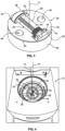
Fig. 1 is a perspective view of an asymmetric rotation mixer including a basket engaged with a catch having a dispenser held therein at an angle relative to horizontal; -
Fig. 2 is an exploded perspective view of the catch and dispenser ofFig. 1 ; -
Fig. 3 is a perspective view of the dispenser received within a cavity of the catch ofFig. 2 ; -
Fig. 4 is an overhead perspective view of the mixer ofFig. 1 ; -
Fig. 5 is a side elevation view of the dispenser received within a cavity of the catch ofFig. 3 ; -
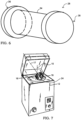
Fig. 6 is a another perspective view of the dispenser ofFigs. 1-5 ; and, -
Fig. 7 is another perspective view of the mixer ofFig. 1 showing the basket exaggerated out from the mixing cavity to emphasis its angle relative to horizontal. - For the purposes of promoting an understanding of the principles of the disclosure, reference will now be made to a number of illustrative embodiments illustrated in the drawings and specific language will be used to describe the same.
- Dynamic mixing, such as rotation mixing, can provide effective, non-invasive mixing of substance. Asymmetric rotation mixing can be particularly fast and effective by imposing centrifugal (centripetal) force on the substance(s) to be mixed. Various containers can be selected for containing the substance(s) to be mixed and undergoing the asymmetric rotation.
- In the illustrative embodiment as shown in
Fig. 1 , anasymmetric rotation mixer 12 having its hatch (door) 14 open to reveal amixing chamber 16 for conducting asymmetric rotation mixing. Themixer 12 illustratively includes arotation basket 18 arranged to receive mixing containers that contain one or substances for rotational mixing. Thebasket 18 is engaged with a rotation drive of themixer 12 that imposes rotational forces on the basket 18 (and on mixing containers engaged with the basket 18). - In the illustrative embodiment as shown in
Fig. 1 , themixer 12 is embodied as a dual axis rotation mixer. As discussed in additional detail herein, themixer 12 illustratively rotates (or revolves; as indicated by arrows 20) thebasket 18 about aprimary axis 15 while simultaneously rotating thebasket 18 itself about a secondary axis 17 (as indicated by arrows 22). Thesecondary axis 17 is illustratively defined through a centroid 24 (or center of mass) of the basket 18 (and ultimately intended to illustrate thecollective centroid 24 of the basket with any received mixing container and its contents). Theprimary axis 15 is offset from thecentroid 24 for asymmetric rotation of the basket 18 (as indicated by arrows 22). - Examples of suitable rotational mixers can be found within
U.S. Patent Nos. 6,099,160 and6,755,565 each issued to Flackett, the disclosures of each of which are incorporated by reference herein, including, but not limited to those, portions disclosing devices, systems, and methods for mixing and associated components and accessories. Such dual axis rotation mixing including asymmetric rotation may be referred to as planetary mixing and/or centrifugal mixing, although these terms may not be entirely accurate and are not intended to limit mixing parameters such as the direction of rotation about each of the dual axes, speed, and/or other geometry relationships. - As shown in
Fig. 1 , themixer 12 is shown to be seated on a level horizontal surface. In the illustrative embodiment, theprimary axis 15 is vertical and the secondary axis is angled relative to theprimary axis 15. In the illustrative embodiment, thebasket 18 is illustratively formed as a hollow cylinder extending along thesecondary axis 17 in its longitudinal dimension. Thebasket 18 is thus illustratively angled relative to theprimary axis 15 in the same manner as thesecondary axis 17. - Referring to
Fig. 1 , as mentioned above, theprimary axis 15 is embodied to be vertical, thus perpendicular (90 degrees) to horizontal. In some embodiments, the primary axis may be within the range of about 70 to about 110 degrees from horizontal. In the illustrative embodiment, as discussed in additional detail herein relative toFigs. 4 and5 , the secondary axis 17 (and thus the basket 18) is arranged at an angle α from the horizontal of about 40 degrees. A receiver (or catch) 26 is engaged within thebasket 18 holding acontainer 28 for rotational mixing. - Referring to
Fig. 2 , thecatch 26 is shown in exploded view with thecontainer 28 for description purposes. Thecatch 26 illustratively includes abody 30 formed with a cylindrical shape having its central axis as thesecondary axis 17 and extending with its longitudinal dimension oriented along the secondary axis 17 (thesecondary axis 17 shown oriented vertically inFig. 2 for description purposes). Thecatch 26 illustratively includes acavity 32 defined in thebody 30 and configured to receive thecontainer 28 to maintain particular orientation during mixing as best shown inFig. 3 . - As shown in
Figs. 2 and3 , thecontainer 28 is illustratively embodied as a dosing dispenser, for example, a metered dosing dispenser for accurate and precise dosing of its contents. Examples of suitable metered dispensers include TOPI-CLICK® as marketed by DOSELOGIX® of Woodstock, Georgia; TOPI-PUMP® as marketed by Tcd, Inc. of Lucedale Mississippi; TICKER® as marketed by Biosrx, Inc. (and/or Folsom Medical Pharmacy) of Folsom, California; among others. In the illustrative embodiment, thecontainer 28 includes acontainer body 34 having a generally cylindrical shape. Thecontainer body 34 illustratively extends longitudinally betweenopposite ends ends body 34. - As illustratively shown in
Fig. 3 , thecavity 32 of thecatch body 30 is illustratively formed complimentary to thecontainer 28 to hold thecontainer 28 in position. In the illustrative embodiment, thecontainer 28 is secured within thecavity 32 by press-fitting (also referred to as friction-fit, snap-fit, and/or interference-fit), and is illustratively configured for selective securing/removal by hand. In some embodiments, thecontainer 28 may be retained within thecavity 32 by any suitable means, for example, a fastener, such as a clip, strap, cover, and/or latch. - Returning briefly to
Fig. 2 , thecavity 32 illustratively includes abase channel 40 adapted to receive thecontainer body 34, and endchannels end container 28. In the illustrative embodiment, thebase channel 40 is formed complimentary to thecontainer body 34 to form the press-fit. In some embodiments, a press-fit may be formed between at least oneend channel end end channels container 28, but in some embodiments, one or more of theend channels ends - In the illustrative embodiment as shown in
Fig. 2 , thecavity 32 is open on a top end face (longitudinal end face) 52 of thecatch body 30 and is closed by a bottom wall 39 of thecatch body 30 that defines a portion of thecavity 32. When seated within thecavity 32, thecontainer 28 illustratively engages the bottom wall 39. The bottom wall 29 illustratively forms adepression 41 accommodating to curvature of thecontainer 28. Thecavity 32 illustratively forms an I-shape, but in some embodiments, may have any suitable shape formed to accommodate thecontainer 28. - As shown in
Fig. 3 , thecatch body 30 illustratively definesholes 46 therein. Theholes 46 can reduce the overall weight of thecatch body 30. In the illustrative embodiment, thecatch body 30 includesside wall 48 having a slight taper in the downward direction (in the orientation as shown inFig. 3 ) along thesecondary axis 17. The taper is illustratively formed complimentary to thebasket 18 which illustratively includes complimentary interior tapering. Thecatch 26 illustratively includes aledge 50 extending from an outer circumference of theside wall 48 of thecatch body 30 near thetop end face 52 of thecatch body 30. - As shown in
Fig. 4 , as mentioned above, thebasket 18 is illustratively arranged to have thesecondary axis 17 angled relative to horizontal (and angled relative to the primary axis 15). InFig. 4 , the offset between thecentroid 24 and theaxis 15 can better observed to create asymmetric rotation of thebasket 18 thereabout. - Referring to
Fig. 5 , the angle α between thebasket 18 and horizontal (dashed line) is illustrated in a side elevation view for clarity. As mentioned above, the basket 18 (and accordingly, thecatch 26 and the container 28) by itssecondary axis 17 is arranged at the angle α relative to the horizontal of about 40 degrees, but in some embodiments, the angle α from the horizontal may be within the range of about 1 to about 89 degrees. Angling thecontainer 28 for dual axis rotation can provide efficiency and effectiveness in mixing its contents. - As shown in the illustrative embodiment of
Fig. 5 , theend 36 of thecontainer 28 is formed as alid 54. Thelid 54 is illustratively selectively secured to thebody 34 by snap-fit engagement, but in some embodiments, may be secured by any suitable means. Thelid 54, as secured in place, illustratively covers the longitudinal end of thecontainer body 34 which includes at least one opening for dispensing contents from within thecontainer body 34. Theend 36 of thecontainer 28 illustratively includes anadjustment dial 56 for incremental rotation to turn a screw shaft extending through thecontainer body 34 to drive a plunger under controlled length to deliver contents of the container body through the at least one opening for metered dispensing. Other dispenser designs, methods, and/or arrangements may be used as discussed above. The longitudinal dimension of thecontainer 28 is illustrated for clarity as line L having thelid 54 and dial 56at opposite ends thereof. - As shown in
Fig. 5 , thecavity 32 formed in thecatch body 30 receives thecontainer 28 to maintain the longitudinal dimension L of thecontainer 28 at an angle β relative to the horizontal. In the illustrative embodiment, the angle β relative to the horizontal is equal to the angle α, but in some embodiments, may be any suitable angle within the range of about 1 to about 89 degrees. Angling thecontainer 28 relative to horizontal can provide advantageous geometries for mixing substance(s) within thecontainer 28. - In
Fig. 5 , theprimary axis 15 is shown offset from thecentroid 24 extending through portions of thebasket 18,catch 26, andcontainer 28, but in some embodiments, may have a greater offset such that theprimary axis 15 does not extend through any portions of thebasket 18,catch 26, andcontainer 28. As mentioned previously, the offset creates the asymmetry in rotation about theprimary axis 15. Together with the speed of rotation about theaxis 15, the offset (radius of rotation) and the angle β of thecontainer 28 determine the amount of centrifugal (centripetal) force applied to the substance(s) to be mixed within thecontainer 28. Other factors effecting mixing forces may include container shape/size and rotation direction. In the illustratively embodiment, the offset is within the range of about 3 to about 60 centimeters. The speed of rotation about theprimary axis 15 is illustratively within the range of about 300 to about 1200 RPM, but in some embodiments, may be within the range of about 50 to about 3500 RPM. - In the illustrative embodiment, the rotation speed about the
secondary axis 17 is proportional to the speed about theprimary axis 15 at a ratio within the range of about 1:1 to about 1:5 (primary:secondary) , but in some embodiments, may be in the range of about 1:0.9 to about 1:2.0. In some embodiments, the rotation speed about thesecondary axis 17 may be independent. In the illustrative embodiment, the rotation about theprimary axis 15 is clockwise (viewed from above, such as inFig. 4 ) and rotation about thesecondary axis 17 is counter clockwise, but in some embodiments, the direction of rotation for either primary andsecondary axes Fig. 5 , a drive shaft connects with thebasket 18 to drive rotation, but in some embodiments, any suitable drive may be used. -
Container 28 is illustratively formed of plastic. In some embodiments, thecontainer 28 may include any suitable material, for example, polypropylene, polyethylene, polystyrene, polyurethane, tin, aluminum, steel, and/or silicon dioxide. The volume of substance within the container is illustratively within the range of about 0.1ml to about 20000ml. - As shown in
Fig. 6 , thecontainer 28 is shown empty and havingbody 34 partly transparent to show that thebody 34 illustratively includes an ovular shape. Thecavity 32, namely thebase channel 40 is illustratively formed to receive the container such that the larger dimension of the ovular shape is oriented generally vertically, but in some embodiments, may be oriented otherwise.Fig. 7 shows themixer 12 having thebasket 18 exaggerated out from thechamber 16 to illustrate the offset between theprimary axis 15 and thecentroid 24, and the angle of thebasket 18 relative to horizontal. - The present disclosure include devices, systems, and methods for maintaining mixing containers at a specific position relative to horizontal to provide geometric advantages in rotational mixing.
- An aspect of the present disclosure may include a mixer catch for holding in relative position a metered dispenser containing substance for mixing under asymmetric rotation of the metered dispenser by a basket of an asymmetric rotation mixer. The mixer catch may include a catch body configured for engagement within the basket of the asymmetric rotation mixer to receive asymmetric rotation. The catch body may be formed complimentary to the basket to maintain relative position about a primary axis of asymmetric rotation and to rotate about a secondary axis. A cavity may be defined in the catch body. The cavity may be configured to receive and maintain the metered dispenser stationary relative to the catch body and to define a longitudinal dimension corresponding to the metered dispenser. In some embodiments, the primary axis may be vertical. In some embodiments, the longitudinal dimension of the cavity may be oriented at an angle from horizontal, the angle being within a range of about 20 degrees to about 70 degrees. In some embodiments, the angle may be within the range of about 30 to about 50 degrees.
- In some embodiments, the primary axis may extend through the catch body. The primary axis is offset from a centroid of the catch body by a distance within the range of about 3 to about 20 centimeters. The catch body may be formed to have a cylindrical shape extending along the secondary axis. The catch body may be tapered for at least a portion of its extent along the secondary axis. In some embodiments, the catch body may include a circumferential ledge formed on an upper end.
- In some embodiments, the cavity may be formed to have an I shape. The cavity may be defined at least partly by an endwall having a depression formed therein. In some embodiments, the dispenser may have an ovular cross-section and the depression includes curvature formed to accommodate the dispenser.
- Another aspect of the present disclosure may include an asymmetric rotation mixer including a basket for holding in relative position a receptacle containing substance for mixing under asymmetric rotation about a primary axis of asymmetric rotation and about a secondary axis of asymmetric rotation. The mixer may include a mixer catch including a catch body configured for engagement within the basket to receive asymmetric rotation. The catch body may formed complimentary to the basket to maintain relative position about the primary axis of asymmetric rotation and to rotate about the secondary axis. A cavity may be defined in the catch body, the cavity configured to receive and maintain the receptacle stationary relative to the catch body and to define a longitudinal dimension corresponding to the receptacle. In some embodiments, the primary axis may be vertical. In some embodiments, the longitudinal dimension of the cavity may be oriented at an angle from horizontal, the angle being within a range of about 20 to about 70 degrees. In some embodiments, the angle may be within the range of 30 to 50 degrees.
- In some embodiments, the primary axis may extend through the catch body. The primary axis may be offset from a centroid of the catch by a distance within the range of about 3 to about 20 centimeters. In some embodiments, the speed of rotation about the primary axis may be within the range of about 300 to about 1200 RPM. In some embodiments, the speed of rotation about the secondary axis may be proportional to the speed of rotation of about the primary axis by a ratio within the range of about 1:1 to about 1:3. Rotation about the primary axis may be clockwise. Rotation about the primary axis may counter clockwise. In some embodiments, the metered dispenser may contain a volume of substance for mixing within the range of about 0.1 to about 20000 ml.
- Another aspect of the present disclosure may include a method of asymmetrical rotation mixing including arranging a metered dispenser within a complimentary cavity of a mixer catch, and rotating the catch about a primary axis and about a secondary axis oriented at an angle relative to the primary axis within the range of about 40 to about 60 degrees. A longitudinal dimension of the dispenser may be arranged generally perpendicular to the secondary axis.
Claims (5)
- A system for the asymmetric rotation of a metered dispenser comprising:(a) an asymmetric rotation mixer having a rotation drive (12), the asymmetric rotation mixer being a dual axis rotation mixer having a hatch (14) and a mixing chamber (16) for conducting asymmetric rotation mixing;(b) a basket (18) engaged with the rotation drive of the asymmetric rotation mixer (12) and configured to receive rotational force about a primary axis (15);(c) a metered dispenser (28) having a body and two opposing ends (36, 38);(d) a mixer catch (26) having a catch body (34) configured for engagement within the basket (18) of the asymmetric rotation mixer (12) to receive asymmetric rotation, the catch body (34) formed complimentary to the basket to maintain relative position about the primary axis (15) of asymmetric rotation and to rotate about a secondary axis (17); and(e) a cavity (32) defined in the catch body (30), the cavity being open on a top end face of said catch body (30) and further configured to receive the metered dispenser (28) such that both opposing ends (36, 38) are secured within said cavity (32), and wherein the cavity (32) is further configured to maintain the metered dispenser (28) stationary relative to the catch body (30) and defining a longitudinal dimension (line L) corresponding to the metered dispenser (28), wherein the longitudinal dimension extends along the top face of the catch body (30);wherein the primary axis (15) is vertical and the longitudinal dimension (line L) of the cavity (32) is oriented at an angle (β) from horizontal, the angle (β) being within a range of about 20 degrees to about 70 degrees.
- The system of Claim 1, wherein the angle (β) is within the range of about 30 to about 50 degrees.
- The system of Claim 1, wherein the primary axis (15) extends through the catch body (30).
- The system of Claim 1, wherein the primary axis (15) is offset from a centroid (24) of the catch body (30) by a distance within the range of about 3 to about 20 centimeters.
- The system of Claim 1, wherein the catch body (30) is formed to have a cylindrical shape extending along the secondary axis (17).
Applications Claiming Priority (2)
| Application Number | Priority Date | Filing Date | Title |
|---|---|---|---|
| US201762517616P | 2017-06-09 | 2017-06-09 | |
| PCT/US2018/036659 WO2018227087A1 (en) | 2017-06-09 | 2018-06-08 | Metered dispenser catch for asymmetric rotation mixer |
Publications (3)
| Publication Number | Publication Date |
|---|---|
| EP3634611A1 EP3634611A1 (en) | 2020-04-15 |
| EP3634611A4 EP3634611A4 (en) | 2021-06-09 |
| EP3634611B1 true EP3634611B1 (en) | 2024-10-16 |
Family
ID=64562864
Family Applications (1)
| Application Number | Title | Priority Date | Filing Date |
|---|---|---|---|
| EP18813859.8A Active EP3634611B1 (en) | 2017-06-09 | 2018-06-08 | A system for asymmetric rotation of a metered dispenser |
Country Status (7)
| Country | Link |
|---|---|
| US (1) | US11478763B2 (en) |
| EP (1) | EP3634611B1 (en) |
| AU (1) | AU2018279724A1 (en) |
| BR (1) | BR112019026063A2 (en) |
| CA (1) | CA3066760A1 (en) |
| ES (1) | ES3004584T3 (en) |
| WO (1) | WO2018227087A1 (en) |
Families Citing this family (3)
| Publication number | Priority date | Publication date | Assignee | Title |
|---|---|---|---|---|
| EP3538071B1 (en) | 2016-11-10 | 2022-09-14 | Medisca Pharmaceutique Inc. | Pharmaceutical compounding methods and systems |
| JP2020111014A (en) * | 2019-01-16 | 2020-07-27 | セイコーエプソン株式会社 | Stirrer |
| US20260015901A1 (en) * | 2022-07-12 | 2026-01-15 | Flacktek Speedmixer, Inc. | Integral locking apparatus using rotational force inflection and methods of use thereof |
Citations (1)
| Publication number | Priority date | Publication date | Assignee | Title |
|---|---|---|---|---|
| US6733170B2 (en) * | 2001-12-03 | 2004-05-11 | Gc Corporation | Mixer for capsule for dental restoration material |
Family Cites Families (26)
| Publication number | Priority date | Publication date | Assignee | Title |
|---|---|---|---|---|
| US281831A (en) * | 1883-07-24 | Wood-screw | ||
| US218142A (en) * | 1879-08-05 | Improvement in screw-bolts | ||
| US391097A (en) * | 1888-10-16 | Island | ||
| US389167A (en) * | 1888-09-04 | rogers | ||
| US659068A (en) * | 1897-12-22 | 1900-10-02 | Hobart B Ives | Adjustable fastener for window-beads. |
| US684799A (en) * | 1900-09-01 | 1901-10-22 | Benjamin Green Devoe | Jar-cover. |
| US1002347A (en) * | 1910-07-18 | 1911-09-05 | John Wemer | Agitator. |
| US1018947A (en) * | 1911-06-10 | 1912-02-27 | Charles Louis Wall | Churn. |
| US2972784A (en) * | 1958-03-04 | 1961-02-28 | Arthur S La Pine & Company | Method of encapsulating a magnet with polytetrafluoroethylene |
| US3679184A (en) | 1969-01-14 | 1972-07-25 | Woodham Cecil H | Mixing devices |
| GB1387402A (en) | 1971-03-02 | 1975-03-19 | Techno Med Ltd | Mixing process and apparatus |
| DK116677A (en) * | 1977-03-17 | 1978-09-18 | J Palsson | MEDICINE BOX WITH SAFETY LAYER |
| CA1132534A (en) | 1978-09-25 | 1982-09-28 | John C. Gall | Material tumbler with non-perpendicular rotation axes |
| US4497581A (en) * | 1979-11-15 | 1985-02-05 | Miller Paint Equipment, Inc. | Paint shaker |
| US4266452A (en) * | 1980-01-14 | 1981-05-12 | Crist Robert M | Oil filter wrench |
| DE4120644C1 (en) | 1991-06-22 | 1993-03-25 | Raimund Andris Gmbh & Co Kg, 7730 Villingen-Schwenningen, De | |
| DE4239284A1 (en) | 1992-11-23 | 1994-05-26 | Hilti Ag | Mixing device for flowable masses |
| JP4291913B2 (en) | 1999-03-03 | 2009-07-08 | 株式会社アサヒ化学研究所 | Mixing and stirring device |
| US6099160A (en) | 1999-03-23 | 2000-08-08 | Flacktek, Inc. | Mixing system for mixing and dispensing reactive materials |
| US6755565B2 (en) | 2002-04-17 | 2004-06-29 | Flacktek, Inc. | Deep holder for dual asymmetric centrifugal mixing system |
| BRPI0516538A (en) * | 2004-10-05 | 2008-09-09 | Sherwin Williams Co | adapter for holding a container in a bucket of a mixer device, apparatus and method for having ink disposed in a container |
| US20070002682A1 (en) | 2005-06-29 | 2007-01-04 | Bausch & Lomb Incorporated | Method of producing liquid solutions comprising fusible solid materials |
| US20070045219A1 (en) * | 2005-08-30 | 2007-03-01 | Nasiatka John R | Moldable threaded closure configured to receive a common household item to facilitate untightening of the closure |
| CN101887951B (en) * | 2009-05-12 | 2013-10-09 | 鸿富锦精密工业(深圳)有限公司 | fixed structure |
| US20120076611A1 (en) * | 2010-09-23 | 2012-03-29 | Ati Properties, Inc. | High Strength Alpha/Beta Titanium Alloy Fasteners and Fastener Stock |
| JP5687038B2 (en) | 2010-11-30 | 2015-03-18 | 株式会社シンキー | Centrifuge |
-
2018
- 2018-06-07 US US16/002,556 patent/US11478763B2/en active Active
- 2018-06-08 AU AU2018279724A patent/AU2018279724A1/en not_active Abandoned
- 2018-06-08 WO PCT/US2018/036659 patent/WO2018227087A1/en not_active Ceased
- 2018-06-08 BR BR112019026063-3A patent/BR112019026063A2/en not_active Application Discontinuation
- 2018-06-08 CA CA3066760A patent/CA3066760A1/en active Pending
- 2018-06-08 ES ES18813859T patent/ES3004584T3/en active Active
- 2018-06-08 EP EP18813859.8A patent/EP3634611B1/en active Active
Patent Citations (1)
| Publication number | Priority date | Publication date | Assignee | Title |
|---|---|---|---|---|
| US6733170B2 (en) * | 2001-12-03 | 2004-05-11 | Gc Corporation | Mixer for capsule for dental restoration material |
Also Published As
| Publication number | Publication date |
|---|---|
| WO2018227087A1 (en) | 2018-12-13 |
| CA3066760A1 (en) | 2018-12-13 |
| EP3634611A4 (en) | 2021-06-09 |
| US11478763B2 (en) | 2022-10-25 |
| BR112019026063A2 (en) | 2020-06-30 |
| US20180353919A1 (en) | 2018-12-13 |
| ES3004584T3 (en) | 2025-03-12 |
| AU2018279724A1 (en) | 2020-01-16 |
| EP3634611A1 (en) | 2020-04-15 |
Similar Documents
| Publication | Publication Date | Title |
|---|---|---|
| US11478763B2 (en) | Metered dispenser catch for asymmetric rotation mixer | |
| RU2223902C2 (en) | Vessel having two or more compartments | |
| UA53612C2 (en) | Closure cap for containers (variants) | |
| JP3561741B2 (en) | Container with two or more compartments | |
| JP2000516183A (en) | Dispenser for two-part composition | |
| US20090178940A1 (en) | Stacked-container reusable bottle, system and method providing flexible use and mixing | |
| JP7462099B2 (en) | Dispensing container with cutter | |
| US6755565B2 (en) | Deep holder for dual asymmetric centrifugal mixing system | |
| EP1305228B1 (en) | Applicator | |
| US20210085566A1 (en) | Formula and powder mixing assembly | |
| EP2156146A2 (en) | Dispenser for powdered foodstuffs | |
| IE862969L (en) | Dosage device | |
| US20100116699A1 (en) | Supplement compartment for beverage container | |
| US20040217138A1 (en) | Dispenser with adjustable lateral powder flow | |
| CN109804227A (en) | A kind of quantifying feed sealer and the container using the quantifying feed sealer | |
| US8919607B2 (en) | Analyte test strip vial | |
| EP0116065A1 (en) | Dispensing bottle and method | |
| US12091228B2 (en) | Dispensing device | |
| US20050072801A1 (en) | Multi-compartmented propel container | |
| JP2021062890A (en) | Note cap | |
| KR101178585B1 (en) | quantitative dispensing apparatus for powders | |
| US20200079560A1 (en) | Beverage container | |
| JP6295460B2 (en) | container | |
| WO2014189784A1 (en) | Dispenser for dispensing precise amounts of powder and the like | |
| KR102017235B1 (en) | Screw type heterogeneous material mixer |
Legal Events
| Date | Code | Title | Description |
|---|---|---|---|
| STAA | Information on the status of an ep patent application or granted ep patent |
Free format text: STATUS: THE INTERNATIONAL PUBLICATION HAS BEEN MADE |
|
| PUAI | Public reference made under article 153(3) epc to a published international application that has entered the european phase |
Free format text: ORIGINAL CODE: 0009012 |
|
| STAA | Information on the status of an ep patent application or granted ep patent |
Free format text: STATUS: REQUEST FOR EXAMINATION WAS MADE |
|
| 17P | Request for examination filed |
Effective date: 20191219 |
|
| AK | Designated contracting states |
Kind code of ref document: A1 Designated state(s): AL AT BE BG CH CY CZ DE DK EE ES FI FR GB GR HR HU IE IS IT LI LT LU LV MC MK MT NL NO PL PT RO RS SE SI SK SM TR |
|
| AX | Request for extension of the european patent |
Extension state: BA ME |
|
| DAV | Request for validation of the european patent (deleted) | ||
| DAX | Request for extension of the european patent (deleted) | ||
| RIC1 | Information provided on ipc code assigned before grant |
Ipc: B01F 15/00 20060101ALI20210204BHEP Ipc: B01F 9/00 20060101AFI20210204BHEP |
|
| A4 | Supplementary search report drawn up and despatched |
Effective date: 20210512 |
|
| RIC1 | Information provided on ipc code assigned before grant |
Ipc: B01F 9/00 20060101AFI20210506BHEP Ipc: B01F 15/00 20060101ALI20210506BHEP |
|
| STAA | Information on the status of an ep patent application or granted ep patent |
Free format text: STATUS: EXAMINATION IS IN PROGRESS |
|
| 17Q | First examination report despatched |
Effective date: 20221201 |
|
| REG | Reference to a national code |
Free format text: PREVIOUS MAIN CLASS: B01F0011000000 Ipc: B01F0029100000 Ref country code: DE Ref legal event code: R079 Ref document number: 602018075568 Country of ref document: DE |
|
| GRAP | Despatch of communication of intention to grant a patent |
Free format text: ORIGINAL CODE: EPIDOSNIGR1 |
|
| STAA | Information on the status of an ep patent application or granted ep patent |
Free format text: STATUS: GRANT OF PATENT IS INTENDED |
|
| RIC1 | Information provided on ipc code assigned before grant |
Ipc: B01F 35/42 20220101ALI20240403BHEP Ipc: B01F 29/34 20220101ALI20240403BHEP Ipc: B01F 29/10 20220101AFI20240403BHEP |
|
| INTG | Intention to grant announced |
Effective date: 20240508 |
|
| GRAS | Grant fee paid |
Free format text: ORIGINAL CODE: EPIDOSNIGR3 |
|
| GRAA | (expected) grant |
Free format text: ORIGINAL CODE: 0009210 |
|
| STAA | Information on the status of an ep patent application or granted ep patent |
Free format text: STATUS: THE PATENT HAS BEEN GRANTED |
|
| AK | Designated contracting states |
Kind code of ref document: B1 Designated state(s): AL AT BE BG CH CY CZ DE DK EE ES FI FR GB GR HR HU IE IS IT LI LT LU LV MC MK MT NL NO PL PT RO RS SE SI SK SM TR |
|
| P01 | Opt-out of the competence of the unified patent court (upc) registered |
Free format text: CASE NUMBER: APP_50633/2024 Effective date: 20240906 |
|
| REG | Reference to a national code |
Ref country code: GB Ref legal event code: FG4D |
|
| REG | Reference to a national code |
Ref country code: CH Ref legal event code: EP |
|
| REG | Reference to a national code |
Ref country code: IE Ref legal event code: FG4D |
|
| REG | Reference to a national code |
Ref country code: DE Ref legal event code: R096 Ref document number: 602018075568 Country of ref document: DE |
|
| REG | Reference to a national code |
Ref country code: NL Ref legal event code: FP |
|
| REG | Reference to a national code |
Ref country code: LT Ref legal event code: MG9D |
|
| REG | Reference to a national code |
Ref country code: ES Ref legal event code: FG2A Ref document number: 3004584 Country of ref document: ES Kind code of ref document: T3 Effective date: 20250312 |
|
| REG | Reference to a national code |
Ref country code: AT Ref legal event code: MK05 Ref document number: 1732505 Country of ref document: AT Kind code of ref document: T Effective date: 20241016 |
|
| PG25 | Lapsed in a contracting state [announced via postgrant information from national office to epo] |
Ref country code: PT Free format text: LAPSE BECAUSE OF FAILURE TO SUBMIT A TRANSLATION OF THE DESCRIPTION OR TO PAY THE FEE WITHIN THE PRESCRIBED TIME-LIMIT Effective date: 20250217 Ref country code: HR Free format text: LAPSE BECAUSE OF FAILURE TO SUBMIT A TRANSLATION OF THE DESCRIPTION OR TO PAY THE FEE WITHIN THE PRESCRIBED TIME-LIMIT Effective date: 20241016 Ref country code: IS Free format text: LAPSE BECAUSE OF FAILURE TO SUBMIT A TRANSLATION OF THE DESCRIPTION OR TO PAY THE FEE WITHIN THE PRESCRIBED TIME-LIMIT Effective date: 20250216 |
|
| PG25 | Lapsed in a contracting state [announced via postgrant information from national office to epo] |
Ref country code: FI Free format text: LAPSE BECAUSE OF FAILURE TO SUBMIT A TRANSLATION OF THE DESCRIPTION OR TO PAY THE FEE WITHIN THE PRESCRIBED TIME-LIMIT Effective date: 20241016 |
|
| PG25 | Lapsed in a contracting state [announced via postgrant information from national office to epo] |
Ref country code: BG Free format text: LAPSE BECAUSE OF FAILURE TO SUBMIT A TRANSLATION OF THE DESCRIPTION OR TO PAY THE FEE WITHIN THE PRESCRIBED TIME-LIMIT Effective date: 20241016 |
|
| PG25 | Lapsed in a contracting state [announced via postgrant information from national office to epo] |
Ref country code: NO Free format text: LAPSE BECAUSE OF FAILURE TO SUBMIT A TRANSLATION OF THE DESCRIPTION OR TO PAY THE FEE WITHIN THE PRESCRIBED TIME-LIMIT Effective date: 20250116 |
|
| PG25 | Lapsed in a contracting state [announced via postgrant information from national office to epo] |
Ref country code: LV Free format text: LAPSE BECAUSE OF FAILURE TO SUBMIT A TRANSLATION OF THE DESCRIPTION OR TO PAY THE FEE WITHIN THE PRESCRIBED TIME-LIMIT Effective date: 20241016 Ref country code: AT Free format text: LAPSE BECAUSE OF FAILURE TO SUBMIT A TRANSLATION OF THE DESCRIPTION OR TO PAY THE FEE WITHIN THE PRESCRIBED TIME-LIMIT Effective date: 20241016 Ref country code: GR Free format text: LAPSE BECAUSE OF FAILURE TO SUBMIT A TRANSLATION OF THE DESCRIPTION OR TO PAY THE FEE WITHIN THE PRESCRIBED TIME-LIMIT Effective date: 20250117 |
|
| PG25 | Lapsed in a contracting state [announced via postgrant information from national office to epo] |
Ref country code: PL Free format text: LAPSE BECAUSE OF FAILURE TO SUBMIT A TRANSLATION OF THE DESCRIPTION OR TO PAY THE FEE WITHIN THE PRESCRIBED TIME-LIMIT Effective date: 20241016 |
|
| PG25 | Lapsed in a contracting state [announced via postgrant information from national office to epo] |
Ref country code: RS Free format text: LAPSE BECAUSE OF FAILURE TO SUBMIT A TRANSLATION OF THE DESCRIPTION OR TO PAY THE FEE WITHIN THE PRESCRIBED TIME-LIMIT Effective date: 20250116 |
|
| PG25 | Lapsed in a contracting state [announced via postgrant information from national office to epo] |
Ref country code: SM Free format text: LAPSE BECAUSE OF FAILURE TO SUBMIT A TRANSLATION OF THE DESCRIPTION OR TO PAY THE FEE WITHIN THE PRESCRIBED TIME-LIMIT Effective date: 20241016 |
|
| PGFP | Annual fee paid to national office [announced via postgrant information from national office to epo] |
Ref country code: DE Payment date: 20250623 Year of fee payment: 8 |
|
| PG25 | Lapsed in a contracting state [announced via postgrant information from national office to epo] |
Ref country code: DK Free format text: LAPSE BECAUSE OF FAILURE TO SUBMIT A TRANSLATION OF THE DESCRIPTION OR TO PAY THE FEE WITHIN THE PRESCRIBED TIME-LIMIT Effective date: 20241016 |
|
| PGFP | Annual fee paid to national office [announced via postgrant information from national office to epo] |
Ref country code: GB Payment date: 20250624 Year of fee payment: 8 |
|
| PGFP | Annual fee paid to national office [announced via postgrant information from national office to epo] |
Ref country code: NL Payment date: 20250623 Year of fee payment: 8 |
|
| REG | Reference to a national code |
Ref country code: DE Ref legal event code: R097 Ref document number: 602018075568 Country of ref document: DE |
|
| PG25 | Lapsed in a contracting state [announced via postgrant information from national office to epo] |
Ref country code: EE Free format text: LAPSE BECAUSE OF FAILURE TO SUBMIT A TRANSLATION OF THE DESCRIPTION OR TO PAY THE FEE WITHIN THE PRESCRIBED TIME-LIMIT Effective date: 20241016 |
|
| PGFP | Annual fee paid to national office [announced via postgrant information from national office to epo] |
Ref country code: FR Payment date: 20250611 Year of fee payment: 8 |
|
| PG25 | Lapsed in a contracting state [announced via postgrant information from national office to epo] |
Ref country code: RO Free format text: LAPSE BECAUSE OF FAILURE TO SUBMIT A TRANSLATION OF THE DESCRIPTION OR TO PAY THE FEE WITHIN THE PRESCRIBED TIME-LIMIT Effective date: 20241016 |
|
| PG25 | Lapsed in a contracting state [announced via postgrant information from national office to epo] |
Ref country code: SK Free format text: LAPSE BECAUSE OF FAILURE TO SUBMIT A TRANSLATION OF THE DESCRIPTION OR TO PAY THE FEE WITHIN THE PRESCRIBED TIME-LIMIT Effective date: 20241016 |
|
| PG25 | Lapsed in a contracting state [announced via postgrant information from national office to epo] |
Ref country code: CZ Free format text: LAPSE BECAUSE OF FAILURE TO SUBMIT A TRANSLATION OF THE DESCRIPTION OR TO PAY THE FEE WITHIN THE PRESCRIBED TIME-LIMIT Effective date: 20241016 |
|
| PLBE | No opposition filed within time limit |
Free format text: ORIGINAL CODE: 0009261 |
|
| STAA | Information on the status of an ep patent application or granted ep patent |
Free format text: STATUS: NO OPPOSITION FILED WITHIN TIME LIMIT |
|
| PG25 | Lapsed in a contracting state [announced via postgrant information from national office to epo] |
Ref country code: SE Free format text: LAPSE BECAUSE OF FAILURE TO SUBMIT A TRANSLATION OF THE DESCRIPTION OR TO PAY THE FEE WITHIN THE PRESCRIBED TIME-LIMIT Effective date: 20241016 |
|
| 26N | No opposition filed |
Effective date: 20250717 |
|
| PGFP | Annual fee paid to national office [announced via postgrant information from national office to epo] |
Ref country code: ES Payment date: 20250702 Year of fee payment: 8 |
|
| PGFP | Annual fee paid to national office [announced via postgrant information from national office to epo] |
Ref country code: IT Payment date: 20250613 Year of fee payment: 8 |
|
| REG | Reference to a national code |
Ref country code: CH Ref legal event code: H13 Free format text: ST27 STATUS EVENT CODE: U-0-0-H10-H13 (AS PROVIDED BY THE NATIONAL OFFICE) Effective date: 20260127 |
|
| PG25 | Lapsed in a contracting state [announced via postgrant information from national office to epo] |
Ref country code: MC Free format text: LAPSE BECAUSE OF FAILURE TO SUBMIT A TRANSLATION OF THE DESCRIPTION OR TO PAY THE FEE WITHIN THE PRESCRIBED TIME-LIMIT Effective date: 20241016 |
|
| PG25 | Lapsed in a contracting state [announced via postgrant information from national office to epo] |
Ref country code: LU Free format text: LAPSE BECAUSE OF NON-PAYMENT OF DUE FEES Effective date: 20250608 |
|
| REG | Reference to a national code |
Ref country code: BE Ref legal event code: MM Effective date: 20250630 |
|
| PG25 | Lapsed in a contracting state [announced via postgrant information from national office to epo] |
Ref country code: IE Free format text: LAPSE BECAUSE OF NON-PAYMENT OF DUE FEES Effective date: 20250608 |
|
| PG25 | Lapsed in a contracting state [announced via postgrant information from national office to epo] |
Ref country code: BE Free format text: LAPSE BECAUSE OF NON-PAYMENT OF DUE FEES Effective date: 20250630 |
|
| PG25 | Lapsed in a contracting state [announced via postgrant information from national office to epo] |
Ref country code: CH Free format text: LAPSE BECAUSE OF NON-PAYMENT OF DUE FEES Effective date: 20250630 |