EP3634501B1 - Sterilizing machine for loose products - Google Patents
Sterilizing machine for loose products Download PDFInfo
- Publication number
- EP3634501B1 EP3634501B1 EP18732925.5A EP18732925A EP3634501B1 EP 3634501 B1 EP3634501 B1 EP 3634501B1 EP 18732925 A EP18732925 A EP 18732925A EP 3634501 B1 EP3634501 B1 EP 3634501B1
- Authority
- EP
- European Patent Office
- Prior art keywords
- loose products
- container
- loading
- machine
- treatment chamber
- Prior art date
- Legal status (The legal status is an assumption and is not a legal conclusion. Google has not performed a legal analysis and makes no representation as to the accuracy of the status listed.)
- Active
Links
Images


Classifications
-
- A—HUMAN NECESSITIES
- A61—MEDICAL OR VETERINARY SCIENCE; HYGIENE
- A61L—METHODS OR APPARATUS FOR STERILISING MATERIALS OR OBJECTS IN GENERAL; DISINFECTION, STERILISATION OR DEODORISATION OF AIR; CHEMICAL ASPECTS OF BANDAGES, DRESSINGS, ABSORBENT PADS OR SURGICAL ARTICLES; MATERIALS FOR BANDAGES, DRESSINGS, ABSORBENT PADS OR SURGICAL ARTICLES
- A61L2/00—Disinfection or sterilisation of materials or objects, in general; Accessories therefor
- A61L2/02—Disinfection or sterilisation of materials or objects, in general; Accessories therefor using physical processes
- A61L2/04—Heat
- A61L2/06—Hot gas
- A61L2/07—Steam
-
- A—HUMAN NECESSITIES
- A61—MEDICAL OR VETERINARY SCIENCE; HYGIENE
- A61L—METHODS OR APPARATUS FOR STERILISING MATERIALS OR OBJECTS IN GENERAL; DISINFECTION, STERILISATION OR DEODORISATION OF AIR; CHEMICAL ASPECTS OF BANDAGES, DRESSINGS, ABSORBENT PADS OR SURGICAL ARTICLES; MATERIALS FOR BANDAGES, DRESSINGS, ABSORBENT PADS OR SURGICAL ARTICLES
- A61L2/00—Disinfection or sterilisation of materials or objects, in general; Accessories therefor
- A61L2/16—Disinfection or sterilisation of materials or objects, in general; Accessories therefor using chemical substances
- A61L2/18—Liquid substances
-
- A—HUMAN NECESSITIES
- A61—MEDICAL OR VETERINARY SCIENCE; HYGIENE
- A61L—METHODS OR APPARATUS FOR STERILISING MATERIALS OR OBJECTS IN GENERAL; DISINFECTION, STERILISATION OR DEODORISATION OF AIR; CHEMICAL ASPECTS OF BANDAGES, DRESSINGS, ABSORBENT PADS OR SURGICAL ARTICLES; MATERIALS FOR BANDAGES, DRESSINGS, ABSORBENT PADS OR SURGICAL ARTICLES
- A61L2/00—Disinfection or sterilisation of materials or objects, in general; Accessories therefor
- A61L2/26—Accessories
-
- A—HUMAN NECESSITIES
- A61—MEDICAL OR VETERINARY SCIENCE; HYGIENE
- A61L—METHODS OR APPARATUS FOR STERILISING MATERIALS OR OBJECTS IN GENERAL; DISINFECTION, STERILISATION OR DEODORISATION OF AIR; CHEMICAL ASPECTS OF BANDAGES, DRESSINGS, ABSORBENT PADS OR SURGICAL ARTICLES; MATERIALS FOR BANDAGES, DRESSINGS, ABSORBENT PADS OR SURGICAL ARTICLES
- A61L2103/00—Materials or objects being the target of disinfection or sterilisation
- A61L2103/23—Containers other than laboratory or medical, e.g. bottles or mail
-
- A—HUMAN NECESSITIES
- A61—MEDICAL OR VETERINARY SCIENCE; HYGIENE
- A61L—METHODS OR APPARATUS FOR STERILISING MATERIALS OR OBJECTS IN GENERAL; DISINFECTION, STERILISATION OR DEODORISATION OF AIR; CHEMICAL ASPECTS OF BANDAGES, DRESSINGS, ABSORBENT PADS OR SURGICAL ARTICLES; MATERIALS FOR BANDAGES, DRESSINGS, ABSORBENT PADS OR SURGICAL ARTICLES
- A61L2202/00—Aspects relating to methods or apparatus for disinfecting or sterilising materials or objects
- A61L2202/10—Apparatus features
- A61L2202/16—Mobile applications, e.g. portable devices, trailers, devices mounted on vehicles
Definitions
- the present invention concerns a sterilizing machine for loose products, for example a sterilizing machine with a rotating drum which can be used, in particular, in the hospital, pharmaceutical or food field, or in the industrial sector for the production of loose products.
- the loose products can be, for example, closing stoppers for test tubes for laboratory analysis, closing stoppers for vials of drugs, or small instruments or objects used in operating theaters or laboratories, or other.
- the loose products can already be sterile when they are produced and sold in packages which are themselves sterile, or are sterilized before each use and reused several times during their working life.
- Rotating drums are known, partitioned into sectors, each containing a desired quantity of loose products to be poured into the individual packs after sterilization.
- the loose products are generally loaded into the treatment chamber provided with the drum by means of a loading zone situated above the treatment chamber.
- a containing sector of the rotating drum faces toward the loading zone on each occasion, in such a way as to introduce a correct quantity of loose products into the containing sector.
- the loading of the loose products through the loading zone can be done manually, or by means of a pneumatic system which sucks the products from a basket and sends them to a metering cylinder located in correspondence with the loading zone of the treatment chamber.
- the loose products are, for example, coated with Teflon, or suchlike, there is a real risk that the loose products can stick to each other in the containing baskets.
- a control which is carried out at the end of the treatment cycle can provide for an operator to open a door of the treatment chamber to verify that possible residual loose products have not remained undesirably in one of the containing sectors of the drum, so as to prevent the residual and treated loose products from mixing with loose products to be treated and/or with loose products of different types.
- One purpose of the present invention is therefore to provide a sterilizing machine which is provided with an effective and automated treatment cycle, in particular with regard to the loading system of the loose products to be treated.
- Another purpose of the present invention is to provide a sterilizing machine which is equipped with a system for loading the loose products to be treated which makes the loading operations of the loose products into the treatment chamber extremely fluid and precise.
- Another purpose of the present invention is to provide a sterilizing machine which keeps the loose products loaded moving, and prevents excessive accumulation and grouping of loose products during loading operations, which would cause a reduction in the overall efficiency of the machine.
- Another purpose of the present invention is to perfect an efficient and precise method to sterilize loose products.
- the Applicant has devised, tested and embodied the present invention to overcome the shortcomings of the state of the art and to obtain these and other purposes and advantages.
- a sterilizing machine for loose products comprises a treatment chamber provided with a loading zone for the loose products to be treated.
- the sterilizing machine comprises, upstream of the treatment chamber, a container for loading the loose products provided with a loading side and an unloading side of the loose products and located in rotation by means of a drive motor around an axis that passes through the loading side and the unloading side; at least one helicoidal guide with several spirals, positioned inside the container and configured to move and guide the loose products from the loading side to the unloading side; at least a pipe for sending the loose products from the container to the treatment chamber; and at least one pneumatic device positioned on the unloading side of the container and configured to introduce the loose products unloaded from the container into the pipe and hence toward the loading zone of the treatment chamber.
- the container can be a rotatable drum provided with a cylindrical casing comprising an internal chamber where the helicoidal guide develops along the axis of rotation.
- the container can comprise, on the loading side, a first tubular element communicating with a hopper for loading the loose products and, on the unloading side, a second tubular element to transfer the loose products toward the pneumatic device.
- the container can comprise truncated cone parts to connect with the tubular elements.
- the first tubular element can be integrated with the rotating container and can be connected to the loading hopper by means of a rotatable joint.
- the second tubular element can be integrated with the rotating container and can be connected, by means of a rotatable joint, to another tubular element to transfer the loose products.
- the machine can comprise a valve for opening and closing the passage of the loose products positioned downstream of the unloading side of the container and upstream of the pneumatic device.
- the machine can comprise a metering device to meter the loose products, positioned downstream of the loading container.
- the metering device can be positioned upstream of a connector connecting with the pneumatic device for sending the loose products to the treatment chamber.
- the machine can comprise a control device inside the treatment chamber.
- the machine can comprise at least a control unit connected at least to the opening and closing valve, to the metering device and to the control device.
- the machine can also comprise a frame provided with rolling elements to position and support the rotatable container.
- the loading container can have an inclination from the top downward from the loading side to the unloading side.
- the present invention also concerns a method for sterilizing loose products, carried out in a sterilizing machine for loose products.
- the method comprises loading the loose products to be treated into a loading container provided with a loading side and an unloading side and rotatable by means of a drive motor around an axis that passes through the loading side and the unloading side; guiding and moving the loose products by means of at least a helicoidal guide with several spirals positioned inside the container and configured to guide and move the loose products from the loading side to the unloading side; and sending the loose products toward a loading zone of a treatment chamber of the sterilizing machine once the loose products have exited from the unloading side of the loading container; the sending is carried out by means of a pneumatic device that introduces the loose products exiting from the unloading side into a pipe provided between the loading side of the treatment chamber and the unloading side of the container.
- a sterilizing machine 10 comprises a treatment chamber 11 in which the loose products P to be treated are housed.
- the drum 12 can rotate around an axis X and is made to rotate by suitable drive means 13.
- the drum 12 is substantially cylindrical in shape and is subdivided into a series of containing sectors 15, able to contain a determinate quantity of loose products P to be treated.
- the containing sectors 15 typically have a pyramidal and widened shape proceeding from the center to the periphery of the drum 12.
- each of the containing sectors 15 comprises a door 37, which can be selectively closed or opened to allow the loading of the loose products P to be treated inside the corresponding containing sector 15 and the unloading of the treated loose products P from the containing sector 15.
- the treatment chamber 11 comprises a loading zone 14 of the loose products P to be treated inside each of the containing sectors 15.
- the loading zone 14, as shown, is positioned on an upper part of the treatment chamber 11.
- the loading zone 14 comprises a loading aperture 30 which can be opened and closed by means of a valve 22, for example a guillotine valve, comprising a shutter 18 which can be translated from an open position to a closed position, or vice versa.
- a valve 22 for example a guillotine valve, comprising a shutter 18 which can be translated from an open position to a closed position, or vice versa.
- the present sterilizing machine 10 also comprises a control device 39 to control the drum 12, in particular the corresponding containing sectors 15.
- the control device 39 can be located in correspondence with the loading aperture 30, so as to verify the correct loading of the containing sector 15 positioned in correspondence with the loading zone 14.
- the control device 39 preferably functioning automatically, can be, for example, a digital camera, an optical sensor or suchlike, and will be associated with a control unit 47 of the sterilizing machine 10.
- the control device 39 can be activated to verify at least the state of the containing sector 15 located in proximity to the loading zone 14.
- control device 39 it is possible to verify the correct presence of loose products P to be treated in the containing sector 15 located in correspondence with the loading zone 14, but also to verify that at the end of the treatment cycle there are no loose products P which, undesirably, have remained in the containing sectors 15, or other.
- the treatment chamber 11 also comprises an unloading aperture 16, from which, on each occasion, the loose products P treated in each containing sector 15 exit.
- the unloading aperture 16 is preferably positioned in a lower part of the sterilizing machine 10, so that the treated loose products P coming from a determinate containing sector 15 pass through the aperture 16 due to gravity.
- the treatment chamber 11 comprises a support frame 23, by means of which, preferably, it is placed at a certain height with respect to the ground, or support plane, S.
- a container 20 is positioned to load the loose products P, comprising a loading side 24 and an unloading side 26.
- the container 20 is made to rotate by a drive motor 38 and around an axis C, which passes through the loading side 24 and the unloading side 26, so as to keep the loose products P continuously in motion and allow a correct movement thereof from the loading side 24 to the unloading side 26.
- the axis C can be the longitudinal central axis of the container 20.
- the container 20 also comprises a helicoidal guide 48 with several spirals 36.
- the helicoidal guide 48 has the function of guiding the loose products P and moving them uniformly from the loading side 24 to the unloading side 26, during the rotation of the container 20 around the axis C.
- the container 20 can be in the form of a rotatable drum provided with a cylindrical casing 32 comprising an internal chamber 35 where the helicoidal guide 48 develops along the axis of rotation C.
- the container 20 can comprise, on the loading side 24, a first tubular element 25 communicating with a loading hopper 40, and, on the unloading side 26, another tubular element 27.
- the drive motor 38 could be connected in a known manner and by suitable transmission elements to at least one of the tubular elements 25 and 27, protruding respectively from the loading side 24 and from the unloading side 26 of the container 20.
- the drive motor 38 could be connected to a toothed element or suchlike provided around the casing 32.
- the casing 32 if substantially cylindrical in shape, can comprise truncated cone parts 33 and 34 located in correspondence with the loading side 24 and the unloading side 26, so as to provide an adequate connection with the tubular elements 25 and 27.
- the container 20 will be supported by a suitable support frame 41.
- the support frame 41 is able to confer on the container 20 an inclination from the top downwards from the loading side 24 to the unloading side 26, so as to promote the passage of the loose products P from the loading side 24 to the unloading side 26.
- the support framework 41 provides, as shown, rolling elements 42, such as wheels or suchlike, to support the rotating container 20, in particular its casing 32.
- the tubular element 25 which protrudes from the loading side 24 and which is integral with the rotating container 20 can be connected to the loading hopper 40 by means of a rotatable joint 21.
- the tubular element 27 which protrudes from the unloading side 26 of the container 20 and which is integral with the rotating container 20 can be connected to another tubular element 29 to transfer the loose products P by means of another rotatable joint 28.
- valve 31 is provided upstream of the tubular element 29 and downstream of the unloading side 26 of the container 20 to open and close the passage of the loose products P.
- the chamber 35 is made, into which the loose products P are introduced, coming from the loading side 24 and comprising said helicoidal guide 48, able to guide and move the loose products P from the loading side 24 to the unloading side 26, during the rotation of the container 20.
- the helicoidal guide 48 can provide suitably shaped and distanced spirals 36, which can be in the form of a screw, a worm screw or suchlike, so as to suitably guide the loose products P from the loading side 24 to the unloading side 26 of the container 20.
- a metering device 43 Downstream of the unloading side 26 of the container 20, in particular downstream of the tubular transfer element 29, a metering device 43 is positioned, for example a metering cylinder, suitable to house a certain quantity of loose products P.
- the quantity of loose products P intended to be poured into a determinate containing sector 15 of the drum 12 is introduced into the metering device 43, depending for example on the type of loose products P, the treatment cycle to be carried out or other.
- the sterilizing machine 10 also comprises a pneumatic device 44 to send, in particular automatically, the loose products P coming from the container 20 toward the loading zone 14 of the treatment chamber 11.
- the sending or transfer of loose products P can be performed by means of a suitable transfer pipe 19, for example a flexible pipe 19.
- the pneumatic device 44 can be, for example, a blower or suchlike, which can be associated with a connector 45, which in turn can be connected to the pipe 19 and to an outlet tubular element 46 of the metering device 43.
- the pipe 19, therefore, can be connected at one end to the connector 45 and, at the other end, to the aperture 30 of the loading zone 14 of the treatment chamber 11.
- a sealing gasket for example a pressurized gasket or suchlike, can be positioned in correspondence with the loading aperture 30.
- the loose products P are therefore loaded automatically and precisely by means of the loading container 20, which keeps the loose products P in motion and allows a suitable transfer thereof from the loading side 24 to the unloading side 26.
- the loose products P to be treated can be loaded from the loading side 24 into the container 20 by means of the hopper 40.
- the container 20 can be made to rotate around the axis C, by means of the drive motor 38, so as to keep the loose products P contained in the internal chamber 35 in motion.
- the loose products P are suitably guided and moved from the loading side 24 to the unloading side 26, from which they can exit through the tubular element 27.
- the loose products P are transferred directly into the pipe 19 and that the pneumatic device 44 can automatically transfer a predetermined quantity of loose products P to the loading zone 14 of the treatment chamber 11, by means of the pipe 19, for example by providing that the valve 31 closes after a certain quantity of loose products P has passed to the tubular element 29.
- the valve 31 to open and close the passage of loose products P could cooperate with the control device 39 located in the loading zone 14, so that, for example, it is closed when the control device 39 detects that the containing sector 15 located in correspondence with the loading zone 14 is filled with the desired quantity of loose products P.
- the loose products P are transferred to the metering device 43, by means of which it is possible to establish the correct quantity of loose products to be sent into each of the containing sectors 15 of the drum 12.
- the pneumatic device 44 will be driven so as to automatically transfer the loose products P to the aperture 30 of the loading zone 14 of the treatment chamber 11, along the pipe 19.
- valve 31 will be closed, so as to prevent other loose products from reaching the metering device 43.
- valve 22 positioned in the loading zone 14 will be kept open and the quantity of loose products P will be introduced into a determinate containing sector 15, which presents itself with the door 37 open in correspondence with the loading aperture 30.
- the door 37 is closed, the drum 12 rotated so as to present another containing sector 15 in correspondence with the loading zone, with the corresponding door 37 open.
- control device 39 can automatically send a "loading completed” signal to the control unit 47 of the sterilizing machine 10, so that, for example, it opens the valve 31 again and activates a new unloading of loose products P to the metering device 43.
- control unit 47 is connected at least to the valve 31, the metering device 43 and the control device 39.
- the transfer of loose products P from the container 20 to the treatment chamber 11 is carried out, according to the methods described above, until all the containing sectors 15 of the drum are filled with the desired quantity of loose products P to be treated.
- the transfer of the loose products P from the container 20 to the pneumatic device 44, and then to the loading zone 14 of the treatment chamber 11, takes place in a very uniform, efficient and precise manner, thanks to the movement to which they are subjected inside the container 20, and therefore thanks in particular to the rotation of the container 20.
- valve 22 is closed by a suitable and automatic translation of the shutter 18, and the sterilization cycle can begin in the treatment chamber 11.
- the loose products P are unloaded from the containing sectors 15 to the unloading aperture 16 of the treatment chamber 11, where they can be collected in suitable containers.
- control device 39 can monitor the operations of the treatment cycle both during the loading step of the loose products P to be subjected to the treatment cycle, and also at the end of the cycle, so as to verify, for example, that possible loose products P treated have not been undesirably trapped inside the containing sectors 15.
- This control is important, as it allows to avoid mixing loose products P to be treated with loose products treated, and also to avoid mixing loose products P of different types and/or belonging to different treatment batches.
- this control takes place automatically thanks to the control device 39.
Landscapes
- Health & Medical Sciences (AREA)
- Epidemiology (AREA)
- Life Sciences & Earth Sciences (AREA)
- Animal Behavior & Ethology (AREA)
- General Health & Medical Sciences (AREA)
- Public Health (AREA)
- Veterinary Medicine (AREA)
- Chemical & Material Sciences (AREA)
- Chemical Kinetics & Catalysis (AREA)
- General Chemical & Material Sciences (AREA)
- Apparatus For Disinfection Or Sterilisation (AREA)
- Food Preservation Except Freezing, Refrigeration, And Drying (AREA)
Description
- The present invention concerns a sterilizing machine for loose products, for example a sterilizing machine with a rotating drum which can be used, in particular, in the hospital, pharmaceutical or food field, or in the industrial sector for the production of loose products.
- The loose products can be, for example, closing stoppers for test tubes for laboratory analysis, closing stoppers for vials of drugs, or small instruments or objects used in operating theaters or laboratories, or other.
- It is known that in the hospital or pharmaceutical field, or other zones, such as the food industry, it is necessary to use sterile products to prevent contamination or alteration of substances with which they come into contact, or to avoid introducing bacteria, germs, other corpuscles or potentially pathogenic or harmful agents into environments where their total absence is required.
- Among such sterile products, in all the above mentioned fields, loose products, even small ones, are normally present, such as, for example, stoppers for closing test tubes intended to contain substances to be subjected to laboratory analysis, or small instruments or objects used in operating theaters or laboratories.
- The loose products can already be sterile when they are produced and sold in packages which are themselves sterile, or are sterilized before each use and reused several times during their working life.
- In some cases the loose products therefore require to be sterilized. Some examples of machines or devices for sterilizing objects are described for example in documents
DE-A-3841930 ,WO-A-2015150581 andEP-A-3064226 . - In other documents, for example documents
US-A-5397535 ,EP-A-0588145 andWO-A-2007014312 operations to sterilize or disinfect objects are described in various ways, also used in the healthcare sector or suchlike. - Moreover, in document
EP-A-1920853 a machine for cleaning and drying objects is described, while in documentJP-A-H11290061 - It is also known to sterilize these loose products in sterilization machines provided with a sealed chamber in which a rotating drum receives the products to be sterilized from a so-called "dirty" loading side, sterilizes them during a treatment cycle normally comprised between 1 and 5 hours, and unloads them from a so-called "sterile" unloading side, where they are generally packaged in sterile packs.
- Rotating drums are known, partitioned into sectors, each containing a desired quantity of loose products to be poured into the individual packs after sterilization.
- As is known, the loose products are generally loaded into the treatment chamber provided with the drum by means of a loading zone situated above the treatment chamber. A containing sector of the rotating drum faces toward the loading zone on each occasion, in such a way as to introduce a correct quantity of loose products into the containing sector.
- The loading of the loose products through the loading zone can be done manually, or by means of a pneumatic system which sucks the products from a basket and sends them to a metering cylinder located in correspondence with the loading zone of the treatment chamber.
- One disadvantage of known sterilizing apparatuses or machines, including the various machines and apparatuses cited in the above documents, is that known loading systems often prove to be not very effective, both in terms of productivity and efficiency, moreover, in general, the loose products inside the baskets are always in a static or stationary situation and therefore there is a risk that they can undesirably accumulate with each other.
- Furthermore, if the loose products are, for example, coated with Teflon, or suchlike, there is a real risk that the loose products can stick to each other in the containing baskets.
- Another disadvantage, moreover, is that often known sterilizing machines are not sufficiently automated and therefore require frequent interventions by the operators, both in the normal steps of loading the loose products, and also, for example, for steps to control the treatment process which is carried out in the various containing sectors of the drum.
- A control which is carried out at the end of the treatment cycle, for example, can provide for an operator to open a door of the treatment chamber to verify that possible residual loose products have not remained undesirably in one of the containing sectors of the drum, so as to prevent the residual and treated loose products from mixing with loose products to be treated and/or with loose products of different types.
- The problems and disadvantages cited above in particular for the loading operations of sterilizing machines with a rotating drum could also be similar in the case of sterilizing machines with a treatment chamber in which there is no rotating drum, but in which, for example, the loose products to be treated are housed in other containing elements.
- Other limitations and disadvantages of conventional solutions and technologies will be clear to a person of skill after reading the remaining part of the present description with reference to the drawings and the description of the embodiments that follow, although it is clear that the description of the state of the art connected to the present description must not be considered an admission that what is described here is already known from the state of the prior art.
- There is therefore a need to perfect a sterilizing machine which can overcome at least one of the disadvantages of the prior art.
- One purpose of the present invention is therefore to provide a sterilizing machine which is provided with an effective and automated treatment cycle, in particular with regard to the loading system of the loose products to be treated.
- Another purpose of the present invention is to provide a sterilizing machine which is equipped with a system for loading the loose products to be treated which makes the loading operations of the loose products into the treatment chamber extremely fluid and precise.
- Another purpose of the present invention is to provide a sterilizing machine which keeps the loose products loaded moving, and prevents excessive accumulation and grouping of loose products during loading operations, which would cause a reduction in the overall efficiency of the machine.
- Another purpose of the present invention is to perfect an efficient and precise method to sterilize loose products.
- The Applicant has devised, tested and embodied the present invention to overcome the shortcomings of the state of the art and to obtain these and other purposes and advantages.
- The present invention is set forth and characterized in the independent claims, while the dependent claims describe other characteristics of the invention or variants to the main inventive idea.
- In accordance with the above purposes, a sterilizing machine for loose products according to the present invention comprises a treatment chamber provided with a loading zone for the loose products to be treated.
- In some embodiments, the sterilizing machine comprises, upstream of the treatment chamber, a container for loading the loose products provided with a loading side and an unloading side of the loose products and located in rotation by means of a drive motor around an axis that passes through the loading side and the unloading side; at least one helicoidal guide with several spirals, positioned inside the container and configured to move and guide the loose products from the loading side to the unloading side; at least a pipe for sending the loose products from the container to the treatment chamber; and at least one pneumatic device positioned on the unloading side of the container and configured to introduce the loose products unloaded from the container into the pipe and hence toward the loading zone of the treatment chamber.
- The container can be a rotatable drum provided with a cylindrical casing comprising an internal chamber where the helicoidal guide develops along the axis of rotation.
- The container can comprise, on the loading side, a first tubular element communicating with a hopper for loading the loose products and, on the unloading side, a second tubular element to transfer the loose products toward the pneumatic device.
- The container can comprise truncated cone parts to connect with the tubular elements.
- The first tubular element can be integrated with the rotating container and can be connected to the loading hopper by means of a rotatable joint.
- The second tubular element can be integrated with the rotating container and can be connected, by means of a rotatable joint, to another tubular element to transfer the loose products.
- The machine can comprise a valve for opening and closing the passage of the loose products positioned downstream of the unloading side of the container and upstream of the pneumatic device.
- The machine can comprise a metering device to meter the loose products, positioned downstream of the loading container.
- The metering device can be positioned upstream of a connector connecting with the pneumatic device for sending the loose products to the treatment chamber.
- The machine can comprise a control device inside the treatment chamber.
- The machine can comprise at least a control unit connected at least to the opening and closing valve, to the metering device and to the control device.
- The machine can also comprise a frame provided with rolling elements to position and support the rotatable container.
- The loading container can have an inclination from the top downward from the loading side to the unloading side.
- The present invention also concerns a method for sterilizing loose products, carried out in a sterilizing machine for loose products. According to a characteristic aspect of the invention the method comprises loading the loose products to be treated into a loading container provided with a loading side and an unloading side and rotatable by means of a drive motor around an axis that passes through the loading side and the unloading side; guiding and moving the loose products by means of at least a helicoidal guide with several spirals positioned inside the container and configured to guide and move the loose products from the loading side to the unloading side; and sending the loose products toward a loading zone of a treatment chamber of the sterilizing machine once the loose products have exited from the unloading side of the loading container; the sending is carried out by means of a pneumatic device that introduces the loose products exiting from the unloading side into a pipe provided between the loading side of the treatment chamber and the unloading side of the container.
- These and other aspects, characteristics and advantages of the present disclosure will be better understood with reference to the following description, drawings and attached claims. The drawings, which are integrated and form part of the present description, show some forms of embodiment of the present invention, and together with the description, are intended to describe the principles of the disclosure.
- The various aspects and characteristics described in the present description can be applied individually where possible. These individual aspects, for example aspects and characteristics described in the attached dependent claims, can be the object of divisional applications.
- It is understood that any aspect or characteristic that is discovered, during the patenting process, to be already known, shall not be claimed and shall be the object of a disclaimer.
- These and other characteristics of the present invention will become apparent from the following description of some embodiments, given as a non-restrictive example with reference to the attached drawings wherein:
-
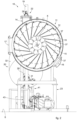
fig. 1 is a three dimensional view of a sterilizing machine according to the present invention; -
fig. 2 is a cross section view of the sterilizing machine infig. 1 ; -
fig. 3 is a view of the sterilizing machine in lateral elevation and in section. - To facilitate comprehension, the same reference numbers have been used, where possible, to identify identical common elements in the drawings. It is understood that elements and characteristics of one embodiment can conveniently be incorporated into other embodiments without further clarifications.
- We will now refer in detail to the various embodiments of the present invention, of which one or more examples are shown in the attached drawings. Each example is supplied by way of illustration of the invention and shall not be understood as a limitation thereof. For example, the characteristics shown or described insomuch as they are part of one embodiment can be adopted on, or in association with, other embodiments to produce another embodiment. It is understood that the present invention shall include all such modifications and variants.
- Before describing these embodiments, we must also clarify that the present description is not limited in its application to details of the construction and disposition of the components as described in the following description using the attached drawings. We must also clarify that the phraseology and terminology used here is for the purposes of description only, and cannot be considered as limitative.
- With reference to the attached drawings, a sterilizing
machine 10 according to the invention comprises atreatment chamber 11 in which the loose products P to be treated are housed. - By way of non-restrictive example, reference will be made in the following description to a sterilizing
machine 10 in whose treatment chamber 11 arotatable drum 12 is housed, however, the description could refer to a different type of sterilizing machine comprising atreatment chamber 11 for the loose products P without arotatable drum 12, but provided, for example, with other containing elements of the loose products P to be treated. - The
drum 12 can rotate around an axis X and is made to rotate by suitable drive means 13. - The
drum 12 is substantially cylindrical in shape and is subdivided into a series of containingsectors 15, able to contain a determinate quantity of loose products P to be treated. - The containing
sectors 15 typically have a pyramidal and widened shape proceeding from the center to the periphery of thedrum 12. - In proximity to the periphery, each of the containing
sectors 15 comprises adoor 37, which can be selectively closed or opened to allow the loading of the loose products P to be treated inside the corresponding containingsector 15 and the unloading of the treated loose products P from the containingsector 15. - The
treatment chamber 11 comprises aloading zone 14 of the loose products P to be treated inside each of the containingsectors 15. - In general, the
loading zone 14, as shown, is positioned on an upper part of thetreatment chamber 11. - The
loading zone 14 comprises aloading aperture 30 which can be opened and closed by means of avalve 22, for example a guillotine valve, comprising ashutter 18 which can be translated from an open position to a closed position, or vice versa. - The
present sterilizing machine 10 also comprises acontrol device 39 to control thedrum 12, in particular the corresponding containingsectors 15. - The
control device 39 can be located in correspondence with theloading aperture 30, so as to verify the correct loading of the containingsector 15 positioned in correspondence with theloading zone 14. - The
control device 39, preferably functioning automatically, can be, for example, a digital camera, an optical sensor or suchlike, and will be associated with acontrol unit 47 of the sterilizingmachine 10. - The
control device 39 can be activated to verify at least the state of the containingsector 15 located in proximity to theloading zone 14. - As we said, therefore, by means of the
control device 39, it is possible to verify the correct presence of loose products P to be treated in the containingsector 15 located in correspondence with theloading zone 14, but also to verify that at the end of the treatment cycle there are no loose products P which, undesirably, have remained in the containingsectors 15, or other. - If any possible loose products P have been undesirably trapped in one of the containing
sectors 15, it is possible to send an alarm and provide to open adoor 17, by means of which the various containingsectors 15 of thedrum 12 can be accessed. - The
treatment chamber 11 also comprises an unloadingaperture 16, from which, on each occasion, the loose products P treated in each containingsector 15 exit. - The unloading
aperture 16 is preferably positioned in a lower part of the sterilizingmachine 10, so that the treated loose products P coming from a determinate containingsector 15 pass through theaperture 16 due to gravity. - The
treatment chamber 11 comprises asupport frame 23, by means of which, preferably, it is placed at a certain height with respect to the ground, or support plane, S. - Upstream of the treatment chamber 11 a
container 20 is positioned to load the loose products P, comprising aloading side 24 and an unloadingside 26. - The
container 20 is made to rotate by adrive motor 38 and around an axis C, which passes through theloading side 24 and the unloadingside 26, so as to keep the loose products P continuously in motion and allow a correct movement thereof from theloading side 24 to the unloadingside 26. The axis C can be the longitudinal central axis of thecontainer 20. - Inside it, the
container 20 also comprises ahelicoidal guide 48 withseveral spirals 36. Thehelicoidal guide 48 has the function of guiding the loose products P and moving them uniformly from theloading side 24 to the unloadingside 26, during the rotation of thecontainer 20 around the axis C. - The
container 20 can be in the form of a rotatable drum provided with acylindrical casing 32 comprising aninternal chamber 35 where thehelicoidal guide 48 develops along the axis of rotation C. - The
container 20 can comprise, on theloading side 24, a firsttubular element 25 communicating with aloading hopper 40, and, on the unloadingside 26, anothertubular element 27. - The
drive motor 38 could be connected in a known manner and by suitable transmission elements to at least one of thetubular elements loading side 24 and from the unloadingside 26 of thecontainer 20. - Alternatively, if the
container 20 comprises the cylindrical shapedcasing 32, as shown by way of example in the case here, thedrive motor 38 could be connected to a toothed element or suchlike provided around thecasing 32. - The
casing 32, if substantially cylindrical in shape, can comprisetruncated cone parts loading side 24 and the unloadingside 26, so as to provide an adequate connection with thetubular elements - The
container 20 will be supported by asuitable support frame 41. - The
support frame 41 is able to confer on thecontainer 20 an inclination from the top downwards from theloading side 24 to the unloadingside 26, so as to promote the passage of the loose products P from theloading side 24 to the unloadingside 26. - The
support framework 41 provides, as shown, rollingelements 42, such as wheels or suchlike, to support the rotatingcontainer 20, in particular itscasing 32. - The
tubular element 25 which protrudes from theloading side 24 and which is integral with the rotatingcontainer 20 can be connected to theloading hopper 40 by means of a rotatable joint 21. - The
tubular element 27 which protrudes from the unloadingside 26 of thecontainer 20 and which is integral with the rotatingcontainer 20 can be connected to anothertubular element 29 to transfer the loose products P by means of another rotatable joint 28. - Upstream of the
tubular element 29 and downstream of the unloadingside 26 of the container 20 avalve 31 is provided to open and close the passage of the loose products P. - Inside the
casing 32 thechamber 35 is made, into which the loose products P are introduced, coming from theloading side 24 and comprising saidhelicoidal guide 48, able to guide and move the loose products P from theloading side 24 to the unloadingside 26, during the rotation of thecontainer 20. - The
helicoidal guide 48 can provide suitably shaped and distancedspirals 36, which can be in the form of a screw, a worm screw or suchlike, so as to suitably guide the loose products P from theloading side 24 to the unloadingside 26 of thecontainer 20. - Downstream of the unloading
side 26 of thecontainer 20, in particular downstream of thetubular transfer element 29, ametering device 43 is positioned, for example a metering cylinder, suitable to house a certain quantity of loose products P. - For example, it can be hypothesized that the quantity of loose products P intended to be poured into a determinate containing
sector 15 of thedrum 12 is introduced into themetering device 43, depending for example on the type of loose products P, the treatment cycle to be carried out or other. - The sterilizing
machine 10 also comprises apneumatic device 44 to send, in particular automatically, the loose products P coming from thecontainer 20 toward theloading zone 14 of thetreatment chamber 11. - The sending or transfer of loose products P can be performed by means of a
suitable transfer pipe 19, for example aflexible pipe 19. - The
pneumatic device 44 can be, for example, a blower or suchlike, which can be associated with aconnector 45, which in turn can be connected to thepipe 19 and to an outlettubular element 46 of themetering device 43. - The
pipe 19, therefore, can be connected at one end to theconnector 45 and, at the other end, to theaperture 30 of theloading zone 14 of thetreatment chamber 11. - A sealing gasket, for example a pressurized gasket or suchlike, can be positioned in correspondence with the
loading aperture 30. - In the
present sterilizing machine 10, the loose products P are therefore loaded automatically and precisely by means of theloading container 20, which keeps the loose products P in motion and allows a suitable transfer thereof from theloading side 24 to the unloadingside 26. - The loose products P to be treated can be loaded from the
loading side 24 into thecontainer 20 by means of thehopper 40. - Once the desired loading of the loose products P has been completed, the
container 20 can be made to rotate around the axis C, by means of thedrive motor 38, so as to keep the loose products P contained in theinternal chamber 35 in motion. - By means of the
helicoidal guide 48, the loose products P are suitably guided and moved from theloading side 24 to the unloadingside 26, from which they can exit through thetubular element 27. - It is possible to provide that the loose products P are transferred directly into the
pipe 19 and that thepneumatic device 44 can automatically transfer a predetermined quantity of loose products P to theloading zone 14 of thetreatment chamber 11, by means of thepipe 19, for example by providing that thevalve 31 closes after a certain quantity of loose products P has passed to thetubular element 29. - The
valve 31 to open and close the passage of loose products P could cooperate with thecontrol device 39 located in theloading zone 14, so that, for example, it is closed when thecontrol device 39 detects that the containingsector 15 located in correspondence with theloading zone 14 is filled with the desired quantity of loose products P. - However, preferably, it is provided that the loose products P are transferred to the
metering device 43, by means of which it is possible to establish the correct quantity of loose products to be sent into each of the containingsectors 15 of thedrum 12. - Substantially then, once the desired quantity of loose products P is present in the
metering device 43, thepneumatic device 44 will be driven so as to automatically transfer the loose products P to theaperture 30 of theloading zone 14 of thetreatment chamber 11, along thepipe 19. - In this step, the
valve 31 will be closed, so as to prevent other loose products from reaching themetering device 43. - Naturally, in this step, the
valve 22 positioned in theloading zone 14 will be kept open and the quantity of loose products P will be introduced into a determinate containingsector 15, which presents itself with thedoor 37 open in correspondence with theloading aperture 30. - Once the loading of the loose products P into the containing
sector 15 has been completed, thedoor 37 is closed, thedrum 12 rotated so as to present another containingsector 15 in correspondence with the loading zone, with the correspondingdoor 37 open. - As we said above, once one containing
sector 15 has been loaded, thecontrol device 39 can automatically send a "loading completed" signal to thecontrol unit 47 of the sterilizingmachine 10, so that, for example, it opens thevalve 31 again and activates a new unloading of loose products P to themetering device 43. - Advantageously, it is possible to provide that the
control unit 47 is connected at least to thevalve 31, themetering device 43 and thecontrol device 39. - Then, a new transfer of loose products P from the
container 20 to themetering device 43 is carried out, so as to be able to send another quantity of loose products P to the other containingsector 15, which is now located in correspondence with theloading zone 14. - Therefore, the transfer of loose products P from the
container 20 to thetreatment chamber 11 is carried out, according to the methods described above, until all the containingsectors 15 of the drum are filled with the desired quantity of loose products P to be treated. - As can be understood, the transfer of the loose products P from the
container 20 to thepneumatic device 44, and then to theloading zone 14 of thetreatment chamber 11, takes place in a very uniform, efficient and precise manner, thanks to the movement to which they are subjected inside thecontainer 20, and therefore thanks in particular to the rotation of thecontainer 20. - Once the loading of the containing
sectors 15 of thedrum 12 has been completed, thevalve 22 is closed by a suitable and automatic translation of theshutter 18, and the sterilization cycle can begin in thetreatment chamber 11. - Once the treatment cycle is completed, the loose products P are unloaded from the containing
sectors 15 to the unloadingaperture 16 of thetreatment chamber 11, where they can be collected in suitable containers. - As we said, the
control device 39 can monitor the operations of the treatment cycle both during the loading step of the loose products P to be subjected to the treatment cycle, and also at the end of the cycle, so as to verify, for example, that possible loose products P treated have not been undesirably trapped inside the containingsectors 15. - This control, as mentioned in the preamble, is important, as it allows to avoid mixing loose products P to be treated with loose products treated, and also to avoid mixing loose products P of different types and/or belonging to different treatment batches.
- Advantageously, in the
present sterilizing machine 10, this control takes place automatically thanks to thecontrol device 39.
Claims (14)
- Sterilizing machine for loose products (P), comprising a treatment chamber (11) provided with a loading zone (14) for said loose products (P) to be treated, said sterilizing machine being characterized in that it comprises, upstream of said treatment chamber (11):a container (20) for loading said loose products (P) provided with a loading side (24) and an unloading side (26) of said loose products (P), said container (20) being made to rotate by means of a drive motor (38) around an axis (C) that passes through said loading side (24) and said unloading side (26);at least one helicoidal guide (48) with several spirals (36), positioned inside said container (20) and configured to move and guide said loose products (P) from said loading side (24) to said unloading side (26),at least a pipe (19) for sending the loose products (P) from said container (20) to said treatment chamber (11); andat least one pneumatic device (44) positioned on the unloading side (26) of said container (20) and configured to introduce said loose products (P) unloaded from said container (20) into said pipe (19) and hence toward said loading zone (14) of said treatment chamber (11).
- Machine as in claim 1, characterized in that said container (20) is a rotatable drum provided with a cylindrical casing (32) comprising an internal chamber (35) where said helicoidal guide (48) develops along said axis (C) of rotation.
- Machine as in claim 1 or 2, characterized in that said container (20) comprises on the loading side (24) a first tubular element (25) communicating with a hopper (40) to load the loose products (P) and, on the unloading side (26), a second tubular element (27) to transfer the loose products (P) toward said pneumatic device (44).
- Machine as in claim 3, characterized in that said container (20) comprises truncated cone parts (33, 34) to connect with said tubular elements (25, 27).
- Machine as in claim 3, characterized in that said first tubular element (25) is integrated with said rotating container (20) and is connected to said loading hopper (40) by means of a rotatable joint (21).
- Machine as in claim 3, characterized in that said second tubular element (27) is integrated with said rotating container (20) and is connected, by means of a rotatable joint (28), to another tubular element (29) to transfer the loose products (P).
- Machine as in any claim hereinbefore, characterized in that it comprises a valve (31) for opening and closing the passage of the loose products (P) positioned downstream of the unloading side (26) of said container (20) and upstream of said pneumatic device (44).
- Machine as in any claim hereinbefore, characterized in that it comprises a metering device (43) to meter said loose products (P), positioned downstream of said loading container (20).
- Machine as in claim 8, characterized in that said metering device (43) is positioned upstream of a connector (45) connecting with said pneumatic device (44) for sending said loose products (P) to said treatment chamber (11).
- Machine as in any claim hereinbefore, characterized in that it comprises a control device (39) inside said treatment chamber (11).
- Machine as in claims 7, 8 and 10, characterized in that it comprises at least a control unit (47) connected at least to said valve (31), to said metering device (43) and to said control device (39).
- Machine as in any claim hereinbefore, characterized in that it comprises a frame (41) provided with rolling elements (42) to position and support the rotatable container (20).
- Machine as in any claim hereinbefore, characterized in that said container (20) has an inclination from the top downward from said loading side (24) to said unloading side (26).
- Method for sterilizing loose products (P), carried out in a sterilizing machine (10) for said loose products (P) as in any claim hereinbefore, said method being characterized in that it comprises loading said loose products (P) to be treated into a loading container (20) provided with a loading side (24) and an unloading side (26) and rotatable by means of a drive motor (38) around an axis (C) that passes through said loading side (24) and said unloading side (26); guiding and moving said loose products by means of at least a helicoidal guide (48) with several spirals (36) positioned inside said container (20) and configured to guide and move said loose products (P) from said loading side (24) to said unloading side (26); and sending said loose products (P) toward a loading zone (14) of a treatment chamber (11) of said sterilizing machine (10) once said loose products (P) have exited from said unloading side (26) of said loading container (20), said sending being carried out by means of a pneumatic device (44) that introduces the loose products (P) exiting from said unloading side (26) into a pipe (19) provided between the loading side (24) of the treatment chamber (11) and said unloading side (26) of the container (20).
Applications Claiming Priority (2)
| Application Number | Priority Date | Filing Date | Title |
|---|---|---|---|
| IT102017000061201A IT201700061201A1 (en) | 2017-06-05 | 2017-06-05 | STERILIZING MACHINE OF BALLS PRODUCTS |
| PCT/IT2018/050098 WO2018225105A2 (en) | 2017-06-05 | 2018-06-04 | Sterilizing machine for loose products |
Publications (2)
| Publication Number | Publication Date |
|---|---|
| EP3634501A2 EP3634501A2 (en) | 2020-04-15 |
| EP3634501B1 true EP3634501B1 (en) | 2023-09-20 |
Family
ID=60294124
Family Applications (1)
| Application Number | Title | Priority Date | Filing Date |
|---|---|---|---|
| EP18732925.5A Active EP3634501B1 (en) | 2017-06-05 | 2018-06-04 | Sterilizing machine for loose products |
Country Status (3)
| Country | Link |
|---|---|
| EP (1) | EP3634501B1 (en) |
| IT (1) | IT201700061201A1 (en) |
| WO (1) | WO2018225105A2 (en) |
Families Citing this family (2)
| Publication number | Priority date | Publication date | Assignee | Title |
|---|---|---|---|---|
| IT201900003773A1 (en) * | 2019-03-14 | 2020-09-14 | Icos Pharma S P A | EQUIPMENT FOR FEEDING LOOSE OBJECTS TO A TREATMENT MACHINE AND RELATED FEEDING PROCEDURE |
| IT201900005154A1 (en) | 2019-04-05 | 2020-10-05 | Icos Pharma S P A | PROCESS OF HANDLING OF LOOSE OBJECTS |
Family Cites Families (13)
| Publication number | Priority date | Publication date | Assignee | Title |
|---|---|---|---|---|
| DE3841930A1 (en) * | 1988-12-13 | 1990-06-21 | Pta Pharma Techn Apparatebau G | Device and method for cleaning, sterilising and drying small objects, especially pharmaceutical seals |
| DE3938546C1 (en) * | 1989-11-21 | 1990-07-12 | Christel 2000 Hamburg De Silber | Feed worms in high temp. hospital waste disinfector - have separate high pressure steam and sub-atmos-zones |
| US5656248A (en) * | 1990-04-19 | 1997-08-12 | Winfield Industries Inc. | Multi-stage infectious waste treatment system |
| US5425925A (en) * | 1990-04-19 | 1995-06-20 | Winfield Industries, Inc. | Multi-stage infectious waste treatment system |
| JPH0448983A (en) * | 1990-06-18 | 1992-02-18 | Masa Kaneko | Apparatus for preparing aggregate for building material from infectious medical waste |
| EP0510276B1 (en) * | 1991-04-23 | 1996-09-11 | Winfield Industries | Multi-stage infectious waste treatment system |
| CH684839A5 (en) * | 1992-09-09 | 1995-01-13 | Sylvan Pilz Ag | A process for the preparation of a solid nutrient substrate for microorganism cultures in its purest form. |
| JP3559982B2 (en) * | 1998-04-13 | 2004-09-02 | 日立プラント建設株式会社 | Method and apparatus for heating and drying pneumatic transport tube for koji making apparatus |
| DE19833024C2 (en) * | 1998-07-23 | 2003-05-15 | Helmut Goeldner | Method and device for disinfecting or sterilizing infected materials |
| US20070023550A1 (en) * | 2005-07-26 | 2007-02-01 | Jakobi Felix F | Hospital waste treatment with improved disinfectant liquid production |
| DE102006053241B4 (en) * | 2006-11-11 | 2012-03-15 | Robert Sporer | Apparatus for treating workpieces or the like |
| DK3125953T3 (en) * | 2014-04-04 | 2018-09-03 | Icos Pharma S P A | Sterilizer for loose products |
| EP3064226B1 (en) * | 2015-03-05 | 2018-02-28 | Icos Pharma S.p.A. | Machine and method for washing and/or sterilizing loose products |
-
2017
- 2017-06-05 IT IT102017000061201A patent/IT201700061201A1/en unknown
-
2018
- 2018-06-04 WO PCT/IT2018/050098 patent/WO2018225105A2/en not_active Ceased
- 2018-06-04 EP EP18732925.5A patent/EP3634501B1/en active Active
Also Published As
| Publication number | Publication date |
|---|---|
| WO2018225105A3 (en) | 2019-01-17 |
| EP3634501A2 (en) | 2020-04-15 |
| WO2018225105A2 (en) | 2018-12-13 |
| IT201700061201A1 (en) | 2018-12-05 |
Similar Documents
| Publication | Publication Date | Title |
|---|---|---|
| RU2140383C1 (en) | Pharmaceutical vessel filler (design versions) | |
| JP5596006B2 (en) | Automatic aseptic liquid collection workstation and collection device | |
| DK3064226T3 (en) | Machine and method for washing and / or sterilizing loose products | |
| EP3125953B1 (en) | Sterilizing machine for loose products | |
| US20210187141A1 (en) | Method and apparatus for sterilizing endoscopes | |
| EP3634502B1 (en) | Sterilizing machine for loose products | |
| JP2022531448A (en) | Equipment and methods for automatically managing atmosphere-controlled processing chambers | |
| CN106061513B (en) | Apparatus and method for transferring sterile product between two containers | |
| WO2018225105A2 (en) | Sterilizing machine for loose products | |
| KR20250109235A (en) | Miniaturised device for automated manufacture of pharmaceutical compositions, and associated method | |
| US11541433B2 (en) | Containing device for a treatment machine, in particular a washing and/or sterilization machine, for loose products | |
| DK3072532T3 (en) | Container device for a machine for washing and / or sterilizing loose products | |
| EP3197782B1 (en) | Device for discharging loose products from a treatment machine | |
| EP4552659A2 (en) | Method to treat loose objects | |
| WO2019123505A1 (en) | Sterilizing machine for loose products and device to discharge loose products from said sterilizing machine | |
| WO2020183510A1 (en) | Apparatus to feed loose objects to a treatment machine and corresponding feed method | |
| JPH0329703A (en) | Rotary type aseptic filling apparatus | |
| WO2025163549A1 (en) | A regulating valve for sealing process chambers | |
| US20190351091A1 (en) | Non-sterile waste removal from a sterile process | |
| KR20120061763A (en) | Automated aseptic liquid collection workstations and collection devices therefore |
Legal Events
| Date | Code | Title | Description |
|---|---|---|---|
| STAA | Information on the status of an ep patent application or granted ep patent |
Free format text: STATUS: UNKNOWN |
|
| STAA | Information on the status of an ep patent application or granted ep patent |
Free format text: STATUS: THE INTERNATIONAL PUBLICATION HAS BEEN MADE |
|
| PUAI | Public reference made under article 153(3) epc to a published international application that has entered the european phase |
Free format text: ORIGINAL CODE: 0009012 |
|
| STAA | Information on the status of an ep patent application or granted ep patent |
Free format text: STATUS: REQUEST FOR EXAMINATION WAS MADE |
|
| 17P | Request for examination filed |
Effective date: 20191218 |
|
| AK | Designated contracting states |
Kind code of ref document: A2 Designated state(s): AL AT BE BG CH CY CZ DE DK EE ES FI FR GB GR HR HU IE IS IT LI LT LU LV MC MK MT NL NO PL PT RO RS SE SI SK SM TR |
|
| AX | Request for extension of the european patent |
Extension state: BA ME |
|
| DAV | Request for validation of the european patent (deleted) | ||
| DAX | Request for extension of the european patent (deleted) | ||
| GRAP | Despatch of communication of intention to grant a patent |
Free format text: ORIGINAL CODE: EPIDOSNIGR1 |
|
| STAA | Information on the status of an ep patent application or granted ep patent |
Free format text: STATUS: GRANT OF PATENT IS INTENDED |
|
| INTG | Intention to grant announced |
Effective date: 20230405 |
|
| P01 | Opt-out of the competence of the unified patent court (upc) registered |
Effective date: 20230418 |
|
| GRAS | Grant fee paid |
Free format text: ORIGINAL CODE: EPIDOSNIGR3 |
|
| GRAA | (expected) grant |
Free format text: ORIGINAL CODE: 0009210 |
|
| STAA | Information on the status of an ep patent application or granted ep patent |
Free format text: STATUS: THE PATENT HAS BEEN GRANTED |
|
| AK | Designated contracting states |
Kind code of ref document: B1 Designated state(s): AL AT BE BG CH CY CZ DE DK EE ES FI FR GB GR HR HU IE IS IT LI LT LU LV MC MK MT NL NO PL PT RO RS SE SI SK SM TR |
|
| REG | Reference to a national code |
Ref country code: GB Ref legal event code: FG4D |
|
| REG | Reference to a national code |
Ref country code: CH Ref legal event code: EP |
|
| REG | Reference to a national code |
Ref country code: DE Ref legal event code: R096 Ref document number: 602018057895 Country of ref document: DE |
|
| REG | Reference to a national code |
Ref country code: IE Ref legal event code: FG4D |
|
| REG | Reference to a national code |
Ref country code: LT Ref legal event code: MG9D |
|
| PG25 | Lapsed in a contracting state [announced via postgrant information from national office to epo] |
Ref country code: GR Free format text: LAPSE BECAUSE OF FAILURE TO SUBMIT A TRANSLATION OF THE DESCRIPTION OR TO PAY THE FEE WITHIN THE PRESCRIBED TIME-LIMIT Effective date: 20231221 |
|
| REG | Reference to a national code |
Ref country code: NL Ref legal event code: MP Effective date: 20230920 |
|
| PG25 | Lapsed in a contracting state [announced via postgrant information from national office to epo] |
Ref country code: SE Free format text: LAPSE BECAUSE OF FAILURE TO SUBMIT A TRANSLATION OF THE DESCRIPTION OR TO PAY THE FEE WITHIN THE PRESCRIBED TIME-LIMIT Effective date: 20230920 Ref country code: RS Free format text: LAPSE BECAUSE OF FAILURE TO SUBMIT A TRANSLATION OF THE DESCRIPTION OR TO PAY THE FEE WITHIN THE PRESCRIBED TIME-LIMIT Effective date: 20230920 Ref country code: NO Free format text: LAPSE BECAUSE OF FAILURE TO SUBMIT A TRANSLATION OF THE DESCRIPTION OR TO PAY THE FEE WITHIN THE PRESCRIBED TIME-LIMIT Effective date: 20231220 Ref country code: LV Free format text: LAPSE BECAUSE OF FAILURE TO SUBMIT A TRANSLATION OF THE DESCRIPTION OR TO PAY THE FEE WITHIN THE PRESCRIBED TIME-LIMIT Effective date: 20230920 Ref country code: LT Free format text: LAPSE BECAUSE OF FAILURE TO SUBMIT A TRANSLATION OF THE DESCRIPTION OR TO PAY THE FEE WITHIN THE PRESCRIBED TIME-LIMIT Effective date: 20230920 Ref country code: HR Free format text: LAPSE BECAUSE OF FAILURE TO SUBMIT A TRANSLATION OF THE DESCRIPTION OR TO PAY THE FEE WITHIN THE PRESCRIBED TIME-LIMIT Effective date: 20230920 Ref country code: GR Free format text: LAPSE BECAUSE OF FAILURE TO SUBMIT A TRANSLATION OF THE DESCRIPTION OR TO PAY THE FEE WITHIN THE PRESCRIBED TIME-LIMIT Effective date: 20231221 Ref country code: FI Free format text: LAPSE BECAUSE OF FAILURE TO SUBMIT A TRANSLATION OF THE DESCRIPTION OR TO PAY THE FEE WITHIN THE PRESCRIBED TIME-LIMIT Effective date: 20230920 |
|
| REG | Reference to a national code |
Ref country code: AT Ref legal event code: MK05 Ref document number: 1612912 Country of ref document: AT Kind code of ref document: T Effective date: 20230920 |
|
| PG25 | Lapsed in a contracting state [announced via postgrant information from national office to epo] |
Ref country code: NL Free format text: LAPSE BECAUSE OF FAILURE TO SUBMIT A TRANSLATION OF THE DESCRIPTION OR TO PAY THE FEE WITHIN THE PRESCRIBED TIME-LIMIT Effective date: 20230920 |
|
| PG25 | Lapsed in a contracting state [announced via postgrant information from national office to epo] |
Ref country code: IS Free format text: LAPSE BECAUSE OF FAILURE TO SUBMIT A TRANSLATION OF THE DESCRIPTION OR TO PAY THE FEE WITHIN THE PRESCRIBED TIME-LIMIT Effective date: 20240120 |
|
| PG25 | Lapsed in a contracting state [announced via postgrant information from national office to epo] |
Ref country code: AT Free format text: LAPSE BECAUSE OF FAILURE TO SUBMIT A TRANSLATION OF THE DESCRIPTION OR TO PAY THE FEE WITHIN THE PRESCRIBED TIME-LIMIT Effective date: 20230920 |
|
| PG25 | Lapsed in a contracting state [announced via postgrant information from national office to epo] |
Ref country code: ES Free format text: LAPSE BECAUSE OF FAILURE TO SUBMIT A TRANSLATION OF THE DESCRIPTION OR TO PAY THE FEE WITHIN THE PRESCRIBED TIME-LIMIT Effective date: 20230920 |
|
| PG25 | Lapsed in a contracting state [announced via postgrant information from national office to epo] |
Ref country code: SM Free format text: LAPSE BECAUSE OF FAILURE TO SUBMIT A TRANSLATION OF THE DESCRIPTION OR TO PAY THE FEE WITHIN THE PRESCRIBED TIME-LIMIT Effective date: 20230920 Ref country code: RO Free format text: LAPSE BECAUSE OF FAILURE TO SUBMIT A TRANSLATION OF THE DESCRIPTION OR TO PAY THE FEE WITHIN THE PRESCRIBED TIME-LIMIT Effective date: 20230920 Ref country code: IS Free format text: LAPSE BECAUSE OF FAILURE TO SUBMIT A TRANSLATION OF THE DESCRIPTION OR TO PAY THE FEE WITHIN THE PRESCRIBED TIME-LIMIT Effective date: 20240120 Ref country code: ES Free format text: LAPSE BECAUSE OF FAILURE TO SUBMIT A TRANSLATION OF THE DESCRIPTION OR TO PAY THE FEE WITHIN THE PRESCRIBED TIME-LIMIT Effective date: 20230920 Ref country code: EE Free format text: LAPSE BECAUSE OF FAILURE TO SUBMIT A TRANSLATION OF THE DESCRIPTION OR TO PAY THE FEE WITHIN THE PRESCRIBED TIME-LIMIT Effective date: 20230920 Ref country code: CZ Free format text: LAPSE BECAUSE OF FAILURE TO SUBMIT A TRANSLATION OF THE DESCRIPTION OR TO PAY THE FEE WITHIN THE PRESCRIBED TIME-LIMIT Effective date: 20230920 Ref country code: AT Free format text: LAPSE BECAUSE OF FAILURE TO SUBMIT A TRANSLATION OF THE DESCRIPTION OR TO PAY THE FEE WITHIN THE PRESCRIBED TIME-LIMIT Effective date: 20230920 Ref country code: SK Free format text: LAPSE BECAUSE OF FAILURE TO SUBMIT A TRANSLATION OF THE DESCRIPTION OR TO PAY THE FEE WITHIN THE PRESCRIBED TIME-LIMIT Effective date: 20230920 Ref country code: PT Free format text: LAPSE BECAUSE OF FAILURE TO SUBMIT A TRANSLATION OF THE DESCRIPTION OR TO PAY THE FEE WITHIN THE PRESCRIBED TIME-LIMIT Effective date: 20240122 |
|
| PG25 | Lapsed in a contracting state [announced via postgrant information from national office to epo] |
Ref country code: PL Free format text: LAPSE BECAUSE OF FAILURE TO SUBMIT A TRANSLATION OF THE DESCRIPTION OR TO PAY THE FEE WITHIN THE PRESCRIBED TIME-LIMIT Effective date: 20230920 |
|
| REG | Reference to a national code |
Ref country code: DE Ref legal event code: R097 Ref document number: 602018057895 Country of ref document: DE |
|
| PG25 | Lapsed in a contracting state [announced via postgrant information from national office to epo] |
Ref country code: DK Free format text: LAPSE BECAUSE OF FAILURE TO SUBMIT A TRANSLATION OF THE DESCRIPTION OR TO PAY THE FEE WITHIN THE PRESCRIBED TIME-LIMIT Effective date: 20230920 |
|
| PLBE | No opposition filed within time limit |
Free format text: ORIGINAL CODE: 0009261 |
|
| STAA | Information on the status of an ep patent application or granted ep patent |
Free format text: STATUS: NO OPPOSITION FILED WITHIN TIME LIMIT |
|
| PG25 | Lapsed in a contracting state [announced via postgrant information from national office to epo] |
Ref country code: DK Free format text: LAPSE BECAUSE OF FAILURE TO SUBMIT A TRANSLATION OF THE DESCRIPTION OR TO PAY THE FEE WITHIN THE PRESCRIBED TIME-LIMIT Effective date: 20230920 |
|
| 26N | No opposition filed |
Effective date: 20240621 |
|
| PG25 | Lapsed in a contracting state [announced via postgrant information from national office to epo] |
Ref country code: SI Free format text: LAPSE BECAUSE OF FAILURE TO SUBMIT A TRANSLATION OF THE DESCRIPTION OR TO PAY THE FEE WITHIN THE PRESCRIBED TIME-LIMIT Effective date: 20230920 |
|
| PG25 | Lapsed in a contracting state [announced via postgrant information from national office to epo] |
Ref country code: SI Free format text: LAPSE BECAUSE OF FAILURE TO SUBMIT A TRANSLATION OF THE DESCRIPTION OR TO PAY THE FEE WITHIN THE PRESCRIBED TIME-LIMIT Effective date: 20230920 |
|
| PG25 | Lapsed in a contracting state [announced via postgrant information from national office to epo] |
Ref country code: BG Free format text: LAPSE BECAUSE OF FAILURE TO SUBMIT A TRANSLATION OF THE DESCRIPTION OR TO PAY THE FEE WITHIN THE PRESCRIBED TIME-LIMIT Effective date: 20230920 |
|
| PG25 | Lapsed in a contracting state [announced via postgrant information from national office to epo] |
Ref country code: BG Free format text: LAPSE BECAUSE OF FAILURE TO SUBMIT A TRANSLATION OF THE DESCRIPTION OR TO PAY THE FEE WITHIN THE PRESCRIBED TIME-LIMIT Effective date: 20230920 |
|
| PG25 | Lapsed in a contracting state [announced via postgrant information from national office to epo] |
Ref country code: MC Free format text: LAPSE BECAUSE OF FAILURE TO SUBMIT A TRANSLATION OF THE DESCRIPTION OR TO PAY THE FEE WITHIN THE PRESCRIBED TIME-LIMIT Effective date: 20230920 |
|
| REG | Reference to a national code |
Ref country code: CH Ref legal event code: PL |
|
| PG25 | Lapsed in a contracting state [announced via postgrant information from national office to epo] |
Ref country code: LU Free format text: LAPSE BECAUSE OF NON-PAYMENT OF DUE FEES Effective date: 20240604 |
|
| GBPC | Gb: european patent ceased through non-payment of renewal fee |
Effective date: 20240604 |
|
| PG25 | Lapsed in a contracting state [announced via postgrant information from national office to epo] |
Ref country code: IE Free format text: LAPSE BECAUSE OF NON-PAYMENT OF DUE FEES Effective date: 20240604 |
|
| PG25 | Lapsed in a contracting state [announced via postgrant information from national office to epo] |
Ref country code: CH Free format text: LAPSE BECAUSE OF NON-PAYMENT OF DUE FEES Effective date: 20240630 Ref country code: BE Free format text: LAPSE BECAUSE OF NON-PAYMENT OF DUE FEES Effective date: 20240630 |
|
| PG25 | Lapsed in a contracting state [announced via postgrant information from national office to epo] |
Ref country code: FR Free format text: LAPSE BECAUSE OF NON-PAYMENT OF DUE FEES Effective date: 20240630 |
|
| PG25 | Lapsed in a contracting state [announced via postgrant information from national office to epo] |
Ref country code: GB Free format text: LAPSE BECAUSE OF NON-PAYMENT OF DUE FEES Effective date: 20240604 |
|
| REG | Reference to a national code |
Ref country code: BE Ref legal event code: MM Effective date: 20240630 |
|
| PGFP | Annual fee paid to national office [announced via postgrant information from national office to epo] |
Ref country code: DE Payment date: 20250626 Year of fee payment: 8 |
|
| PGFP | Annual fee paid to national office [announced via postgrant information from national office to epo] |
Ref country code: IT Payment date: 20250609 Year of fee payment: 8 |
|
| PG25 | Lapsed in a contracting state [announced via postgrant information from national office to epo] |
Ref country code: CY Free format text: LAPSE BECAUSE OF FAILURE TO SUBMIT A TRANSLATION OF THE DESCRIPTION OR TO PAY THE FEE WITHIN THE PRESCRIBED TIME-LIMIT; INVALID AB INITIO Effective date: 20180604 |
|
| PG25 | Lapsed in a contracting state [announced via postgrant information from national office to epo] |
Ref country code: HU Free format text: LAPSE BECAUSE OF FAILURE TO SUBMIT A TRANSLATION OF THE DESCRIPTION OR TO PAY THE FEE WITHIN THE PRESCRIBED TIME-LIMIT; INVALID AB INITIO Effective date: 20180604 |