EP3634331B1 - Composite dressings for improved granulation and reduced maceration with negative-pressure treatment - Google Patents
Composite dressings for improved granulation and reduced maceration with negative-pressure treatment Download PDFInfo
- Publication number
- EP3634331B1 EP3634331B1 EP18733490.9A EP18733490A EP3634331B1 EP 3634331 B1 EP3634331 B1 EP 3634331B1 EP 18733490 A EP18733490 A EP 18733490A EP 3634331 B1 EP3634331 B1 EP 3634331B1
- Authority
- EP
- European Patent Office
- Prior art keywords
- layer
- dressing
- apertures
- wound
- tissue
- Prior art date
- Legal status (The legal status is an assumption and is not a legal conclusion. Google has not performed a legal analysis and makes no representation as to the accuracy of the status listed.)
- Active
Links
- 238000011282 treatment Methods 0.000 title description 22
- 238000002803 maceration Methods 0.000 title description 7
- 238000005469 granulation Methods 0.000 title description 5
- 230000003179 granulation Effects 0.000 title description 5
- 230000002829 reductive effect Effects 0.000 title description 3
- 239000002131 composite material Substances 0.000 title description 2
- 239000012530 fluid Substances 0.000 claims description 110
- 230000002209 hydrophobic effect Effects 0.000 claims description 11
- 229920006254 polymer film Polymers 0.000 claims description 10
- 230000004044 response Effects 0.000 claims description 6
- 229920000642 polymer Polymers 0.000 claims description 5
- 208000027418 Wounds and injury Diseases 0.000 description 124
- 206010052428 Wound Diseases 0.000 description 123
- 210000001519 tissue Anatomy 0.000 description 105
- 238000002560 therapeutic procedure Methods 0.000 description 58
- 238000012360 testing method Methods 0.000 description 49
- 239000000853 adhesive Substances 0.000 description 41
- 230000001070 adhesive effect Effects 0.000 description 41
- 239000000463 material Substances 0.000 description 27
- 239000000243 solution Substances 0.000 description 22
- 239000006260 foam Substances 0.000 description 15
- 241001465754 Metazoa Species 0.000 description 14
- 239000007788 liquid Substances 0.000 description 14
- 238000000034 method Methods 0.000 description 14
- 210000003491 skin Anatomy 0.000 description 13
- 206010063560 Excessive granulation tissue Diseases 0.000 description 11
- 210000001126 granulation tissue Anatomy 0.000 description 11
- 238000005259 measurement Methods 0.000 description 11
- 230000008859 change Effects 0.000 description 9
- 238000004891 communication Methods 0.000 description 9
- 239000004020 conductor Substances 0.000 description 9
- 210000002615 epidermis Anatomy 0.000 description 9
- 239000004814 polyurethane Substances 0.000 description 9
- 230000008901 benefit Effects 0.000 description 8
- 239000000499 gel Substances 0.000 description 8
- -1 polyethylene Polymers 0.000 description 8
- 238000003860 storage Methods 0.000 description 8
- 230000001225 therapeutic effect Effects 0.000 description 8
- XLYOFNOQVPJJNP-UHFFFAOYSA-N water Chemical compound O XLYOFNOQVPJJNP-UHFFFAOYSA-N 0.000 description 8
- 238000003466 welding Methods 0.000 description 8
- 239000004599 antimicrobial Substances 0.000 description 7
- 238000000576 coating method Methods 0.000 description 7
- 230000037361 pathway Effects 0.000 description 7
- 229920001296 polysiloxane Polymers 0.000 description 7
- 229920002635 polyurethane Polymers 0.000 description 7
- 239000004698 Polyethylene Substances 0.000 description 6
- ISAOCJYIOMOJEB-UHFFFAOYSA-N benzoin Chemical compound C=1C=CC=CC=1C(O)C(=O)C1=CC=CC=C1 ISAOCJYIOMOJEB-UHFFFAOYSA-N 0.000 description 6
- 239000011248 coating agent Substances 0.000 description 6
- 238000009826 distribution Methods 0.000 description 6
- 229920000573 polyethylene Polymers 0.000 description 6
- 239000011148 porous material Substances 0.000 description 6
- FAPWRFPIFSIZLT-UHFFFAOYSA-M Sodium chloride Chemical compound [Na+].[Cl-] FAPWRFPIFSIZLT-UHFFFAOYSA-M 0.000 description 5
- 238000010168 coupling process Methods 0.000 description 5
- 238000005859 coupling reaction Methods 0.000 description 5
- 210000000416 exudates and transudate Anatomy 0.000 description 5
- 239000000945 filler Substances 0.000 description 5
- 208000014674 injury Diseases 0.000 description 5
- 230000014759 maintenance of location Effects 0.000 description 5
- 238000009581 negative-pressure wound therapy Methods 0.000 description 5
- 229920000728 polyester Polymers 0.000 description 5
- 238000012545 processing Methods 0.000 description 5
- 239000011780 sodium chloride Substances 0.000 description 5
- FEFNLMIFMCISIM-UHFFFAOYSA-N 1-methyl-4-nitro-5-(4-nitrophenyl)sulfanylimidazole Chemical compound CN1C=NC([N+]([O-])=O)=C1SC1=CC=C([N+]([O-])=O)C=C1 FEFNLMIFMCISIM-UHFFFAOYSA-N 0.000 description 4
- LFQSCWFLJHTTHZ-UHFFFAOYSA-N Ethanol Chemical compound CCO LFQSCWFLJHTTHZ-UHFFFAOYSA-N 0.000 description 4
- 208000032843 Hemorrhage Diseases 0.000 description 4
- 239000004952 Polyamide Substances 0.000 description 4
- 230000000740 bleeding effect Effects 0.000 description 4
- 239000003795 chemical substances by application Substances 0.000 description 4
- 230000008878 coupling Effects 0.000 description 4
- 230000006870 function Effects 0.000 description 4
- 230000000670 limiting effect Effects 0.000 description 4
- 229920002647 polyamide Polymers 0.000 description 4
- 230000009467 reduction Effects 0.000 description 4
- 230000000284 resting effect Effects 0.000 description 4
- 238000012795 verification Methods 0.000 description 4
- 230000000007 visual effect Effects 0.000 description 4
- 206010015548 Euthanasia Diseases 0.000 description 3
- 206010061218 Inflammation Diseases 0.000 description 3
- 206010030113 Oedema Diseases 0.000 description 3
- 239000004721 Polyphenylene oxide Substances 0.000 description 3
- 229920001247 Reticulated foam Polymers 0.000 description 3
- 244000028419 Styrax benzoin Species 0.000 description 3
- 235000000126 Styrax benzoin Nutrition 0.000 description 3
- 235000008411 Sumatra benzointree Nutrition 0.000 description 3
- 208000025865 Ulcer Diseases 0.000 description 3
- 230000002411 adverse Effects 0.000 description 3
- 229960002130 benzoin Drugs 0.000 description 3
- 238000005520 cutting process Methods 0.000 description 3
- 238000011156 evaluation Methods 0.000 description 3
- 235000019382 gum benzoic Nutrition 0.000 description 3
- 238000011065 in-situ storage Methods 0.000 description 3
- 230000004054 inflammatory process Effects 0.000 description 3
- 239000002245 particle Substances 0.000 description 3
- 230000002093 peripheral effect Effects 0.000 description 3
- 229920000570 polyether Polymers 0.000 description 3
- 229920000098 polyolefin Polymers 0.000 description 3
- 229920006126 semicrystalline polymer Polymers 0.000 description 3
- 238000007920 subcutaneous administration Methods 0.000 description 3
- 230000000699 topical effect Effects 0.000 description 3
- 230000008733 trauma Effects 0.000 description 3
- 231100000397 ulcer Toxicity 0.000 description 3
- 238000009827 uniform distribution Methods 0.000 description 3
- 241000894006 Bacteria Species 0.000 description 2
- RTZKZFJDLAIYFH-UHFFFAOYSA-N Diethyl ether Chemical compound CCOCC RTZKZFJDLAIYFH-UHFFFAOYSA-N 0.000 description 2
- WZUVPPKBWHMQCE-UHFFFAOYSA-N Haematoxylin Chemical compound C12=CC(O)=C(O)C=C2CC2(O)C1C1=CC=C(O)C(O)=C1OC2 WZUVPPKBWHMQCE-UHFFFAOYSA-N 0.000 description 2
- 239000004372 Polyvinyl alcohol Substances 0.000 description 2
- 239000004820 Pressure-sensitive adhesive Substances 0.000 description 2
- 239000003522 acrylic cement Substances 0.000 description 2
- 229920006397 acrylic thermoplastic Polymers 0.000 description 2
- 238000004458 analytical method Methods 0.000 description 2
- 238000010171 animal model Methods 0.000 description 2
- 238000007906 compression Methods 0.000 description 2
- 230000006835 compression Effects 0.000 description 2
- 230000006378 damage Effects 0.000 description 2
- 230000007423 decrease Effects 0.000 description 2
- 230000003247 decreasing effect Effects 0.000 description 2
- 238000013461 design Methods 0.000 description 2
- 238000010586 diagram Methods 0.000 description 2
- SUPCQIBBMFXVTL-UHFFFAOYSA-N ethyl 2-methylprop-2-enoate Chemical compound CCOC(=O)C(C)=C SUPCQIBBMFXVTL-UHFFFAOYSA-N 0.000 description 2
- 239000005038 ethylene vinyl acetate Substances 0.000 description 2
- 230000035876 healing Effects 0.000 description 2
- 239000000416 hydrocolloid Substances 0.000 description 2
- 239000000017 hydrogel Substances 0.000 description 2
- WQYVRQLZKVEZGA-UHFFFAOYSA-N hypochlorite Chemical compound Cl[O-] WQYVRQLZKVEZGA-UHFFFAOYSA-N 0.000 description 2
- 230000006872 improvement Effects 0.000 description 2
- 230000001788 irregular Effects 0.000 description 2
- 238000004519 manufacturing process Methods 0.000 description 2
- 210000003205 muscle Anatomy 0.000 description 2
- 230000017074 necrotic cell death Effects 0.000 description 2
- 238000000879 optical micrograph Methods 0.000 description 2
- 239000012188 paraffin wax Substances 0.000 description 2
- 229920001200 poly(ethylene-vinyl acetate) Polymers 0.000 description 2
- 229920003229 poly(methyl methacrylate) Polymers 0.000 description 2
- 229920000139 polyethylene terephthalate Polymers 0.000 description 2
- 239000005020 polyethylene terephthalate Substances 0.000 description 2
- 229920002451 polyvinyl alcohol Polymers 0.000 description 2
- 230000008569 process Effects 0.000 description 2
- 238000007789 sealing Methods 0.000 description 2
- SQGYOTSLMSWVJD-UHFFFAOYSA-N silver(1+) nitrate Chemical compound [Ag+].[O-]N(=O)=O SQGYOTSLMSWVJD-UHFFFAOYSA-N 0.000 description 2
- 239000002904 solvent Substances 0.000 description 2
- 229920006249 styrenic copolymer Polymers 0.000 description 2
- 238000001356 surgical procedure Methods 0.000 description 2
- ISXSCDLOGDJUNJ-UHFFFAOYSA-N tert-butyl prop-2-enoate Chemical compound CC(C)(C)OC(=O)C=C ISXSCDLOGDJUNJ-UHFFFAOYSA-N 0.000 description 2
- 230000036572 transepidermal water loss Effects 0.000 description 2
- CPKVUHPKYQGHMW-UHFFFAOYSA-N 1-ethenylpyrrolidin-2-one;molecular iodine Chemical compound II.C=CN1CCCC1=O CPKVUHPKYQGHMW-UHFFFAOYSA-N 0.000 description 1
- ZCYVEMRRCGMTRW-UHFFFAOYSA-N 7553-56-2 Chemical compound [I] ZCYVEMRRCGMTRW-UHFFFAOYSA-N 0.000 description 1
- 229940123208 Biguanide Drugs 0.000 description 1
- GHXZTYHSJHQHIJ-UHFFFAOYSA-N Chlorhexidine Chemical compound C=1C=C(Cl)C=CC=1NC(N)=NC(N)=NCCCCCCN=C(N)N=C(N)NC1=CC=C(Cl)C=C1 GHXZTYHSJHQHIJ-UHFFFAOYSA-N 0.000 description 1
- 229920002943 EPDM rubber Polymers 0.000 description 1
- 206010051814 Eschar Diseases 0.000 description 1
- 229920000181 Ethylene propylene rubber Polymers 0.000 description 1
- 244000043261 Hevea brasiliensis Species 0.000 description 1
- 206010028851 Necrosis Diseases 0.000 description 1
- 229920000459 Nitrile rubber Polymers 0.000 description 1
- 239000005062 Polybutadiene Substances 0.000 description 1
- 229920002614 Polyether block amide Polymers 0.000 description 1
- 229920002413 Polyhexanide Polymers 0.000 description 1
- 229920005830 Polyurethane Foam Polymers 0.000 description 1
- 229920000153 Povidone-iodine Polymers 0.000 description 1
- NINIDFKCEFEMDL-UHFFFAOYSA-N Sulfur Chemical compound [S] NINIDFKCEFEMDL-UHFFFAOYSA-N 0.000 description 1
- 241000282898 Sus scrofa Species 0.000 description 1
- 241001016073 Sus scrofa scrofa Species 0.000 description 1
- 206010051373 Wound haemorrhage Diseases 0.000 description 1
- 210000000683 abdominal cavity Anatomy 0.000 description 1
- 150000001252 acrylic acid derivatives Chemical class 0.000 description 1
- 230000001154 acute effect Effects 0.000 description 1
- 210000000577 adipose tissue Anatomy 0.000 description 1
- 229910052782 aluminium Inorganic materials 0.000 description 1
- XAGFODPZIPBFFR-UHFFFAOYSA-N aluminium Chemical compound [Al] XAGFODPZIPBFFR-UHFFFAOYSA-N 0.000 description 1
- 150000001412 amines Chemical class 0.000 description 1
- 210000003484 anatomy Anatomy 0.000 description 1
- 230000000845 anti-microbial effect Effects 0.000 description 1
- 230000001580 bacterial effect Effects 0.000 description 1
- 230000004888 barrier function Effects 0.000 description 1
- 230000009286 beneficial effect Effects 0.000 description 1
- 150000004283 biguanides Chemical class 0.000 description 1
- 230000005540 biological transmission Effects 0.000 description 1
- 238000001574 biopsy Methods 0.000 description 1
- 208000034158 bleeding Diseases 0.000 description 1
- 230000000903 blocking effect Effects 0.000 description 1
- 230000017531 blood circulation Effects 0.000 description 1
- 210000000988 bone and bone Anatomy 0.000 description 1
- DQXBYHZEEUGOBF-UHFFFAOYSA-N but-3-enoic acid;ethene Chemical compound C=C.OC(=O)CC=C DQXBYHZEEUGOBF-UHFFFAOYSA-N 0.000 description 1
- JEDYYFXHPAIBGR-UHFFFAOYSA-N butafenacil Chemical compound O=C1N(C)C(C(F)(F)F)=CC(=O)N1C1=CC=C(Cl)C(C(=O)OC(C)(C)C(=O)OCC=C)=C1 JEDYYFXHPAIBGR-UHFFFAOYSA-N 0.000 description 1
- 229920005549 butyl rubber Polymers 0.000 description 1
- 210000000845 cartilage Anatomy 0.000 description 1
- 238000005266 casting Methods 0.000 description 1
- 125000002091 cationic group Chemical group 0.000 description 1
- 210000004027 cell Anatomy 0.000 description 1
- 238000012412 chemical coupling Methods 0.000 description 1
- 229960003260 chlorhexidine Drugs 0.000 description 1
- 230000001684 chronic effect Effects 0.000 description 1
- 230000003750 conditioning effect Effects 0.000 description 1
- 210000002808 connective tissue Anatomy 0.000 description 1
- 229910052802 copper Inorganic materials 0.000 description 1
- 239000010949 copper Substances 0.000 description 1
- 230000007547 defect Effects 0.000 description 1
- 230000002950 deficient Effects 0.000 description 1
- 239000008367 deionised water Substances 0.000 description 1
- 230000001419 dependent effect Effects 0.000 description 1
- 210000004207 dermis Anatomy 0.000 description 1
- 238000011161 development Methods 0.000 description 1
- 206010012601 diabetes mellitus Diseases 0.000 description 1
- 239000012153 distilled water Substances 0.000 description 1
- 230000002500 effect on skin Effects 0.000 description 1
- 230000000694 effects Effects 0.000 description 1
- 229920001971 elastomer Polymers 0.000 description 1
- 239000013536 elastomeric material Substances 0.000 description 1
- 238000005516 engineering process Methods 0.000 description 1
- 230000002708 enhancing effect Effects 0.000 description 1
- 230000007613 environmental effect Effects 0.000 description 1
- YQGOJNYOYNNSMM-UHFFFAOYSA-N eosin Chemical compound [Na+].OC(=O)C1=CC=CC=C1C1=C2C=C(Br)C(=O)C(Br)=C2OC2=C(Br)C(O)=C(Br)C=C21 YQGOJNYOYNNSMM-UHFFFAOYSA-N 0.000 description 1
- 210000002919 epithelial cell Anatomy 0.000 description 1
- 210000000981 epithelium Anatomy 0.000 description 1
- 231100000333 eschar Toxicity 0.000 description 1
- 239000000835 fiber Substances 0.000 description 1
- NBVXSUQYWXRMNV-UHFFFAOYSA-N fluoromethane Chemical compound FC NBVXSUQYWXRMNV-UHFFFAOYSA-N 0.000 description 1
- 230000037313 granulation tissue formation Effects 0.000 description 1
- 230000023597 hemostasis Effects 0.000 description 1
- 239000002874 hemostatic agent Substances 0.000 description 1
- 229920001600 hydrophobic polymer Polymers 0.000 description 1
- 230000002706 hydrostatic effect Effects 0.000 description 1
- 229920002681 hypalon Polymers 0.000 description 1
- 208000015181 infectious disease Diseases 0.000 description 1
- 230000002401 inhibitory effect Effects 0.000 description 1
- 230000003993 interaction Effects 0.000 description 1
- 229910052740 iodine Inorganic materials 0.000 description 1
- 239000011630 iodine Substances 0.000 description 1
- 229920000554 ionomer Polymers 0.000 description 1
- 230000007794 irritation Effects 0.000 description 1
- 239000012948 isocyanate Substances 0.000 description 1
- 150000002513 isocyanates Chemical class 0.000 description 1
- 239000000644 isotonic solution Substances 0.000 description 1
- 238000010030 laminating Methods 0.000 description 1
- 210000003041 ligament Anatomy 0.000 description 1
- 230000007246 mechanism Effects 0.000 description 1
- 229920002529 medical grade silicone Polymers 0.000 description 1
- 239000012528 membrane Substances 0.000 description 1
- 238000007431 microscopic evaluation Methods 0.000 description 1
- 230000005012 migration Effects 0.000 description 1
- 238000013508 migration Methods 0.000 description 1
- 239000000203 mixture Substances 0.000 description 1
- 238000012986 modification Methods 0.000 description 1
- 230000004048 modification Effects 0.000 description 1
- 239000003607 modifier Substances 0.000 description 1
- 230000004660 morphological change Effects 0.000 description 1
- 238000013425 morphometry Methods 0.000 description 1
- 229920003052 natural elastomer Polymers 0.000 description 1
- 229920001194 natural rubber Polymers 0.000 description 1
- 230000001537 neural effect Effects 0.000 description 1
- 230000003287 optical effect Effects 0.000 description 1
- 206010033675 panniculitis Diseases 0.000 description 1
- 239000006072 paste Substances 0.000 description 1
- 229940021222 peritoneal dialysis isotonic solution Drugs 0.000 description 1
- 230000035699 permeability Effects 0.000 description 1
- 229920003023 plastic Polymers 0.000 description 1
- 239000004033 plastic Substances 0.000 description 1
- 229920001084 poly(chloroprene) Polymers 0.000 description 1
- 229920002857 polybutadiene Polymers 0.000 description 1
- 229920001195 polyisoprene Polymers 0.000 description 1
- 238000006116 polymerization reaction Methods 0.000 description 1
- 229920005862 polyol Polymers 0.000 description 1
- 150000003077 polyols Chemical class 0.000 description 1
- 229920001021 polysulfide Polymers 0.000 description 1
- 239000005077 polysulfide Substances 0.000 description 1
- 150000008117 polysulfides Polymers 0.000 description 1
- 229920006264 polyurethane film Polymers 0.000 description 1
- 239000011496 polyurethane foam Substances 0.000 description 1
- 229920000036 polyvinylpyrrolidone Polymers 0.000 description 1
- 239000001267 polyvinylpyrrolidone Substances 0.000 description 1
- 235000013855 polyvinylpyrrolidone Nutrition 0.000 description 1
- 229960001621 povidone-iodine Drugs 0.000 description 1
- 230000035755 proliferation Effects 0.000 description 1
- 239000005060 rubber Substances 0.000 description 1
- 239000013464 silicone adhesive Substances 0.000 description 1
- 239000004447 silicone coating Substances 0.000 description 1
- 229920002379 silicone rubber Polymers 0.000 description 1
- 229910052709 silver Inorganic materials 0.000 description 1
- 239000004332 silver Substances 0.000 description 1
- 229910001961 silver nitrate Inorganic materials 0.000 description 1
- 238000004513 sizing Methods 0.000 description 1
- 238000010561 standard procedure Methods 0.000 description 1
- 230000001954 sterilising effect Effects 0.000 description 1
- 238000004659 sterilization and disinfection Methods 0.000 description 1
- 229920003048 styrene butadiene rubber Polymers 0.000 description 1
- 210000004304 subcutaneous tissue Anatomy 0.000 description 1
- 239000000126 substance Substances 0.000 description 1
- 229910052717 sulfur Inorganic materials 0.000 description 1
- 239000011593 sulfur Substances 0.000 description 1
- 230000008961 swelling Effects 0.000 description 1
- 210000002435 tendon Anatomy 0.000 description 1
- 150000003606 tin compounds Chemical class 0.000 description 1
- DVKJHBMWWAPEIU-UHFFFAOYSA-N toluene 2,4-diisocyanate Chemical compound CC1=CC=C(N=C=O)C=C1N=C=O DVKJHBMWWAPEIU-UHFFFAOYSA-N 0.000 description 1
- 230000000472 traumatic effect Effects 0.000 description 1
- 238000011269 treatment regimen Methods 0.000 description 1
- 238000011144 upstream manufacturing Methods 0.000 description 1
- 230000002792 vascular Effects 0.000 description 1
- 201000002282 venous insufficiency Diseases 0.000 description 1
- 238000013022 venting Methods 0.000 description 1
- 239000002699 waste material Substances 0.000 description 1
Images


Classifications
-
- A61F13/05—
-
- A—HUMAN NECESSITIES
- A61—MEDICAL OR VETERINARY SCIENCE; HYGIENE
- A61F—FILTERS IMPLANTABLE INTO BLOOD VESSELS; PROSTHESES; DEVICES PROVIDING PATENCY TO, OR PREVENTING COLLAPSING OF, TUBULAR STRUCTURES OF THE BODY, e.g. STENTS; ORTHOPAEDIC, NURSING OR CONTRACEPTIVE DEVICES; FOMENTATION; TREATMENT OR PROTECTION OF EYES OR EARS; BANDAGES, DRESSINGS OR ABSORBENT PADS; FIRST-AID KITS
- A61F13/00—Bandages or dressings; Absorbent pads
- A61F13/02—Adhesive plasters or dressings
- A61F13/0203—Adhesive plasters or dressings having a fluid handling member
- A61F13/0223—Adhesive plasters or dressings having a fluid handling member characterized by parametric properties of the fluid handling layer, e.g. absorbency, wicking capacity, liquid distribution
-
- A—HUMAN NECESSITIES
- A61—MEDICAL OR VETERINARY SCIENCE; HYGIENE
- A61F—FILTERS IMPLANTABLE INTO BLOOD VESSELS; PROSTHESES; DEVICES PROVIDING PATENCY TO, OR PREVENTING COLLAPSING OF, TUBULAR STRUCTURES OF THE BODY, e.g. STENTS; ORTHOPAEDIC, NURSING OR CONTRACEPTIVE DEVICES; FOMENTATION; TREATMENT OR PROTECTION OF EYES OR EARS; BANDAGES, DRESSINGS OR ABSORBENT PADS; FIRST-AID KITS
- A61F13/00—Bandages or dressings; Absorbent pads
- A61F13/15—Absorbent pads, e.g. sanitary towels, swabs or tampons for external or internal application to the body; Supporting or fastening means therefor; Tampon applicators
- A61F13/15203—Properties of the article, e.g. stiffness or absorbency
-
- A—HUMAN NECESSITIES
- A61—MEDICAL OR VETERINARY SCIENCE; HYGIENE
- A61F—FILTERS IMPLANTABLE INTO BLOOD VESSELS; PROSTHESES; DEVICES PROVIDING PATENCY TO, OR PREVENTING COLLAPSING OF, TUBULAR STRUCTURES OF THE BODY, e.g. STENTS; ORTHOPAEDIC, NURSING OR CONTRACEPTIVE DEVICES; FOMENTATION; TREATMENT OR PROTECTION OF EYES OR EARS; BANDAGES, DRESSINGS OR ABSORBENT PADS; FIRST-AID KITS
- A61F13/00—Bandages or dressings; Absorbent pads
- A61F13/15—Absorbent pads, e.g. sanitary towels, swabs or tampons for external or internal application to the body; Supporting or fastening means therefor; Tampon applicators
- A61F13/53—Absorbent pads, e.g. sanitary towels, swabs or tampons for external or internal application to the body; Supporting or fastening means therefor; Tampon applicators characterised by the absorbing medium
- A61F13/534—Absorbent pads, e.g. sanitary towels, swabs or tampons for external or internal application to the body; Supporting or fastening means therefor; Tampon applicators characterised by the absorbing medium having an inhomogeneous composition through the thickness of the pad
- A61F13/537—Absorbent pads, e.g. sanitary towels, swabs or tampons for external or internal application to the body; Supporting or fastening means therefor; Tampon applicators characterised by the absorbing medium having an inhomogeneous composition through the thickness of the pad characterised by a layer facilitating or inhibiting flow in one direction or plane, e.g. a wicking layer
-
- A—HUMAN NECESSITIES
- A61—MEDICAL OR VETERINARY SCIENCE; HYGIENE
- A61L—METHODS OR APPARATUS FOR STERILISING MATERIALS OR OBJECTS IN GENERAL; DISINFECTION, STERILISATION OR DEODORISATION OF AIR; CHEMICAL ASPECTS OF BANDAGES, DRESSINGS, ABSORBENT PADS OR SURGICAL ARTICLES; MATERIALS FOR BANDAGES, DRESSINGS, ABSORBENT PADS OR SURGICAL ARTICLES
- A61L15/00—Chemical aspects of, or use of materials for, bandages, dressings or absorbent pads
- A61L15/16—Bandages, dressings or absorbent pads for physiological fluids such as urine or blood, e.g. sanitary towels, tampons
- A61L15/22—Bandages, dressings or absorbent pads for physiological fluids such as urine or blood, e.g. sanitary towels, tampons containing macromolecular materials
- A61L15/225—Mixtures of macromolecular compounds
-
- A—HUMAN NECESSITIES
- A61—MEDICAL OR VETERINARY SCIENCE; HYGIENE
- A61L—METHODS OR APPARATUS FOR STERILISING MATERIALS OR OBJECTS IN GENERAL; DISINFECTION, STERILISATION OR DEODORISATION OF AIR; CHEMICAL ASPECTS OF BANDAGES, DRESSINGS, ABSORBENT PADS OR SURGICAL ARTICLES; MATERIALS FOR BANDAGES, DRESSINGS, ABSORBENT PADS OR SURGICAL ARTICLES
- A61L15/00—Chemical aspects of, or use of materials for, bandages, dressings or absorbent pads
- A61L15/16—Bandages, dressings or absorbent pads for physiological fluids such as urine or blood, e.g. sanitary towels, tampons
- A61L15/42—Use of materials characterised by their function or physical properties
- A61L15/425—Porous materials, e.g. foams or sponges
-
- A—HUMAN NECESSITIES
- A61—MEDICAL OR VETERINARY SCIENCE; HYGIENE
- A61M—DEVICES FOR INTRODUCING MEDIA INTO, OR ONTO, THE BODY; DEVICES FOR TRANSDUCING BODY MEDIA OR FOR TAKING MEDIA FROM THE BODY; DEVICES FOR PRODUCING OR ENDING SLEEP OR STUPOR
- A61M1/00—Suction or pumping devices for medical purposes; Devices for carrying-off, for treatment of, or for carrying-over, body-liquids; Drainage systems
- A61M1/90—Negative pressure wound therapy devices, i.e. devices for applying suction to a wound to promote healing, e.g. including a vacuum dressing
- A61M1/91—Suction aspects of the dressing
- A61M1/915—Constructional details of the pressure distribution manifold
-
- A—HUMAN NECESSITIES
- A61—MEDICAL OR VETERINARY SCIENCE; HYGIENE
- A61M—DEVICES FOR INTRODUCING MEDIA INTO, OR ONTO, THE BODY; DEVICES FOR TRANSDUCING BODY MEDIA OR FOR TAKING MEDIA FROM THE BODY; DEVICES FOR PRODUCING OR ENDING SLEEP OR STUPOR
- A61M1/00—Suction or pumping devices for medical purposes; Devices for carrying-off, for treatment of, or for carrying-over, body-liquids; Drainage systems
- A61M1/90—Negative pressure wound therapy devices, i.e. devices for applying suction to a wound to promote healing, e.g. including a vacuum dressing
- A61M1/96—Suction control thereof
- A61M1/962—Suction control thereof having pumping means on the suction site, e.g. miniature pump on dressing or dressing capable of exerting suction
-
- A—HUMAN NECESSITIES
- A61—MEDICAL OR VETERINARY SCIENCE; HYGIENE
- A61F—FILTERS IMPLANTABLE INTO BLOOD VESSELS; PROSTHESES; DEVICES PROVIDING PATENCY TO, OR PREVENTING COLLAPSING OF, TUBULAR STRUCTURES OF THE BODY, e.g. STENTS; ORTHOPAEDIC, NURSING OR CONTRACEPTIVE DEVICES; FOMENTATION; TREATMENT OR PROTECTION OF EYES OR EARS; BANDAGES, DRESSINGS OR ABSORBENT PADS; FIRST-AID KITS
- A61F13/00—Bandages or dressings; Absorbent pads
- A61F13/02—Adhesive plasters or dressings
- A61F13/0203—Adhesive plasters or dressings having a fluid handling member
- A61F13/0206—Adhesive plasters or dressings having a fluid handling member the fluid handling member being absorbent fibrous layer, e.g. woven or nonwoven absorbent pad, island dressings
-
- A—HUMAN NECESSITIES
- A61—MEDICAL OR VETERINARY SCIENCE; HYGIENE
- A61F—FILTERS IMPLANTABLE INTO BLOOD VESSELS; PROSTHESES; DEVICES PROVIDING PATENCY TO, OR PREVENTING COLLAPSING OF, TUBULAR STRUCTURES OF THE BODY, e.g. STENTS; ORTHOPAEDIC, NURSING OR CONTRACEPTIVE DEVICES; FOMENTATION; TREATMENT OR PROTECTION OF EYES OR EARS; BANDAGES, DRESSINGS OR ABSORBENT PADS; FIRST-AID KITS
- A61F13/00—Bandages or dressings; Absorbent pads
- A61F13/02—Adhesive plasters or dressings
- A61F13/0203—Adhesive plasters or dressings having a fluid handling member
- A61F13/0213—Adhesive plasters or dressings having a fluid handling member the fluid handling member being a layer of hydrocoloid, gel forming material
-
- A—HUMAN NECESSITIES
- A61—MEDICAL OR VETERINARY SCIENCE; HYGIENE
- A61F—FILTERS IMPLANTABLE INTO BLOOD VESSELS; PROSTHESES; DEVICES PROVIDING PATENCY TO, OR PREVENTING COLLAPSING OF, TUBULAR STRUCTURES OF THE BODY, e.g. STENTS; ORTHOPAEDIC, NURSING OR CONTRACEPTIVE DEVICES; FOMENTATION; TREATMENT OR PROTECTION OF EYES OR EARS; BANDAGES, DRESSINGS OR ABSORBENT PADS; FIRST-AID KITS
- A61F13/00—Bandages or dressings; Absorbent pads
- A61F2013/00089—Wound bandages
- A61F2013/00217—Wound bandages not adhering to the wound
-
- A—HUMAN NECESSITIES
- A61—MEDICAL OR VETERINARY SCIENCE; HYGIENE
- A61F—FILTERS IMPLANTABLE INTO BLOOD VESSELS; PROSTHESES; DEVICES PROVIDING PATENCY TO, OR PREVENTING COLLAPSING OF, TUBULAR STRUCTURES OF THE BODY, e.g. STENTS; ORTHOPAEDIC, NURSING OR CONTRACEPTIVE DEVICES; FOMENTATION; TREATMENT OR PROTECTION OF EYES OR EARS; BANDAGES, DRESSINGS OR ABSORBENT PADS; FIRST-AID KITS
- A61F13/00—Bandages or dressings; Absorbent pads
- A61F2013/00089—Wound bandages
- A61F2013/00246—Wound bandages in a special way pervious to air or vapours
- A61F2013/00251—Wound bandages in a special way pervious to air or vapours with macroscopic openings
-
- A—HUMAN NECESSITIES
- A61—MEDICAL OR VETERINARY SCIENCE; HYGIENE
- A61F—FILTERS IMPLANTABLE INTO BLOOD VESSELS; PROSTHESES; DEVICES PROVIDING PATENCY TO, OR PREVENTING COLLAPSING OF, TUBULAR STRUCTURES OF THE BODY, e.g. STENTS; ORTHOPAEDIC, NURSING OR CONTRACEPTIVE DEVICES; FOMENTATION; TREATMENT OR PROTECTION OF EYES OR EARS; BANDAGES, DRESSINGS OR ABSORBENT PADS; FIRST-AID KITS
- A61F13/00—Bandages or dressings; Absorbent pads
- A61F13/15—Absorbent pads, e.g. sanitary towels, swabs or tampons for external or internal application to the body; Supporting or fastening means therefor; Tampon applicators
- A61F13/53—Absorbent pads, e.g. sanitary towels, swabs or tampons for external or internal application to the body; Supporting or fastening means therefor; Tampon applicators characterised by the absorbing medium
- A61F13/534—Absorbent pads, e.g. sanitary towels, swabs or tampons for external or internal application to the body; Supporting or fastening means therefor; Tampon applicators characterised by the absorbing medium having an inhomogeneous composition through the thickness of the pad
- A61F2013/53445—Absorbent pads, e.g. sanitary towels, swabs or tampons for external or internal application to the body; Supporting or fastening means therefor; Tampon applicators characterised by the absorbing medium having an inhomogeneous composition through the thickness of the pad from several sheets
-
- A—HUMAN NECESSITIES
- A61—MEDICAL OR VETERINARY SCIENCE; HYGIENE
- A61F—FILTERS IMPLANTABLE INTO BLOOD VESSELS; PROSTHESES; DEVICES PROVIDING PATENCY TO, OR PREVENTING COLLAPSING OF, TUBULAR STRUCTURES OF THE BODY, e.g. STENTS; ORTHOPAEDIC, NURSING OR CONTRACEPTIVE DEVICES; FOMENTATION; TREATMENT OR PROTECTION OF EYES OR EARS; BANDAGES, DRESSINGS OR ABSORBENT PADS; FIRST-AID KITS
- A61F13/00—Bandages or dressings; Absorbent pads
- A61F13/15—Absorbent pads, e.g. sanitary towels, swabs or tampons for external or internal application to the body; Supporting or fastening means therefor; Tampon applicators
- A61F13/53—Absorbent pads, e.g. sanitary towels, swabs or tampons for external or internal application to the body; Supporting or fastening means therefor; Tampon applicators characterised by the absorbing medium
- A61F13/534—Absorbent pads, e.g. sanitary towels, swabs or tampons for external or internal application to the body; Supporting or fastening means therefor; Tampon applicators characterised by the absorbing medium having an inhomogeneous composition through the thickness of the pad
- A61F13/537—Absorbent pads, e.g. sanitary towels, swabs or tampons for external or internal application to the body; Supporting or fastening means therefor; Tampon applicators characterised by the absorbing medium having an inhomogeneous composition through the thickness of the pad characterised by a layer facilitating or inhibiting flow in one direction or plane, e.g. a wicking layer
- A61F2013/53765—Absorbent pads, e.g. sanitary towels, swabs or tampons for external or internal application to the body; Supporting or fastening means therefor; Tampon applicators characterised by the absorbing medium having an inhomogeneous composition through the thickness of the pad characterised by a layer facilitating or inhibiting flow in one direction or plane, e.g. a wicking layer characterized by its geometry
- A61F2013/53782—Absorbent pads, e.g. sanitary towels, swabs or tampons for external or internal application to the body; Supporting or fastening means therefor; Tampon applicators characterised by the absorbing medium having an inhomogeneous composition through the thickness of the pad characterised by a layer facilitating or inhibiting flow in one direction or plane, e.g. a wicking layer characterized by its geometry with holes
-
- A—HUMAN NECESSITIES
- A61—MEDICAL OR VETERINARY SCIENCE; HYGIENE
- A61M—DEVICES FOR INTRODUCING MEDIA INTO, OR ONTO, THE BODY; DEVICES FOR TRANSDUCING BODY MEDIA OR FOR TAKING MEDIA FROM THE BODY; DEVICES FOR PRODUCING OR ENDING SLEEP OR STUPOR
- A61M1/00—Suction or pumping devices for medical purposes; Devices for carrying-off, for treatment of, or for carrying-over, body-liquids; Drainage systems
- A61M1/90—Negative pressure wound therapy devices, i.e. devices for applying suction to a wound to promote healing, e.g. including a vacuum dressing
- A61M1/98—Containers specifically adapted for negative pressure wound therapy
- A61M1/984—Containers specifically adapted for negative pressure wound therapy portable on the body
- A61M1/985—Containers specifically adapted for negative pressure wound therapy portable on the body the dressing itself forming the collection container
Definitions
- the invention set forth in the appended claims relates generally to tissue treatment systems and more particularly, but without limitation, to dressings for tissue treatment with negative pressure.
- Negative-pressure therapy may provide a number of benefits, including migration of epithelial and subcutaneous tissues, improved blood flow, and micro-deformation of tissue at a wound site. Together, these benefits can increase development of granulation tissue and reduce healing times.
- WO 01/85248 A1 and WO 2016/015001 A2 descibe dressings that can be used with negative pressure
- a dressing for treating a tissue site with negative pressure comprising: a first layer comprising a polymer film having a plurality of fluid restrictions through the polymer film that are configured to expand in response to a pressure gradient across the polymer film; a second layer coupled to the first layer, the second layer comprising a manifold; a third layer coupled to the second layer opposite the first layer, the third layer comprising a polymer drape; and a fourth layer coupled to the first layer opposite the second layer, the fourth layer comprising a hydrophobic gel having a plurality of apertures.
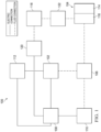
- Figure 1 is a simplified functional block diagram of an example embodiment of a therapy system 100 that can provide negative-pressure therapy with instillation of topical treatment solutions to a tissue site in accordance with this specification.
- tissue site in this context broadly refers to a wound, defect, or other treatment target located on or within tissue, including but not limited to, a surface wound, bone tissue, adipose tissue, muscle tissue, neural tissue, dermal tissue, vascular tissue, connective tissue, cartilage, tendons, or ligaments.
- tissue site may also refer to areas of any tissue that are not necessarily wounded or defective, but are instead areas in which it may be desirable to add or promote the growth of additional tissue. For example, negative pressure may be applied to a tissue site to grow additional tissue that may be harvested and transplanted.
- a surface wound is a wound on the surface of a body that is exposed to the outer surface of the body, such an injury or damage to the epidermis, dermis, and/or subcutaneous layers.
- Surface wounds may include ulcers or closed incisions, for example.
- a surface wound, as used herein, does not include wounds within an intra-abdominal cavity.
- a wound may include chronic, acute, traumatic, subacute, and dehisced wounds, partial-thickness burns, ulcers (such as diabetic, pressure, or venous insufficiency ulcers), flaps, and grafts, for example.
- the therapy system 100 may include a source or supply of negative pressure, such as a negative-pressure source 102, a dressing 104, a fluid container, such as a container 106, and a regulator or controller, such as a controller 108, for example. Additionally, the therapy system 100 may include sensors to measure operating parameters and provide feedback signals to the controller 108 indicative of the operating parameters. As illustrated in Figure 1 , for example, the therapy system 100 may include a pressure sensor 110, an electric sensor 112, or both, coupled to the controller 108. As illustrated in the example of Figure 1 , the dressing 104 may comprise or consist essentially of one or more dressing layers, such as a tissue interface 114, a cover 116, or both in some embodiments.
- the therapy system 100 may also include a source of instillation solution.
- a solution source 118 may be fluidly coupled to the dressing 104, as illustrated in the example embodiment of Figure 1 .
- the solution source 118 may be fluidly coupled to a positive-pressure source such as the positive-pressure source 120, a negative-pressure source such as the negative-pressure source 102, or both in some embodiments.
- a regulator such as an instillation regulator 122, may also be fluidly coupled to the solution source 118 and the dressing 104 to ensure proper dosage of instillation solution (e.g. saline) to a tissue site.
- the instillation regulator 122 may comprise a piston that can be pneumatically actuated by the negative-pressure source 102 to draw instillation solution from the solution source during a negative-pressure interval and to instill the solution to a dressing during a venting interval.
- the controller 108 may be coupled to the negative-pressure source 102, the positive-pressure source 120, or both, to control dosage of instillation solution to a tissue site.
- the instillation regulator 122 may also be fluidly coupled to the negative-pressure source 102 through the dressing 104, as illustrated in the example of Figure 1 .
- Some components of the therapy system 100 may be housed within or used in conjunction with other components, such as sensors, processing units, alarm indicators, memory, databases, software, display devices, or user interfaces that further facilitate therapy.
- the negative-pressure source 102 may be combined with the solution source 118, the controller 108 and other components into a therapy unit.
- components of the therapy system 100 may be coupled directly or indirectly.
- the negative-pressure source 102 may be directly coupled to the container 106, and may be indirectly coupled to the dressing 104 through the container 106. Coupling may include fluid, mechanical, thermal, electrical, or chemical coupling (such as a chemical bond), or some combination of coupling in some contexts.
- the negative-pressure source 102 may be electrically coupled to the controller 108.
- the negative-pressure source maybe fluidly coupled to one or more distribution components, which provide a fluid path to a tissue site.
- components may also be coupled by virtue of physical proximity, being integral to a single structure, or being formed from the same piece of material.
- a distribution component is preferably detachable, and may be disposable, reusable, or recyclable.
- the dressing 104 and the container 106 are illustrative of distribution components.
- a fluid conductor is another illustrative example of a distribution component.
- a tube is an elongated, cylindrical structure with some flexibility, but the geometry and rigidity may vary.
- some fluid conductors may be molded into or otherwise integrally combined with other components.
- Distribution components may also include or comprise interfaces or fluid ports to facilitate coupling and de-coupling other components, including sensors and data communication devices.
- a dressing interface may facilitate coupling a fluid conductor to the dressing 104.
- such a dressing interface may be a SENSAT.R.A.C. TM Pad available from KCI of San Antonio, Texas.
- a negative-pressure supply such as the negative-pressure source 102, may be a reservoir of air at a negative pressure, or may be a manual or electrically-powered device, such as a vacuum pump, a suction pump, a wall suction port available at many healthcare facilities, or a micro-pump, for example.
- Negative pressure generally refers to a pressure less than a local ambient pressure, such as the ambient pressure in a local environment external to a sealed therapeutic environment. In many cases, the local ambient pressure may also be the atmospheric pressure at which a tissue site is located. Alternatively, the pressure may be less than a hydrostatic pressure associated with tissue at the tissue site. Unless otherwise indicated, values of pressure stated herein are gauge pressures.
- references to increases in negative pressure typically refer to a decrease in absolute pressure, while decreases in negative pressure typically refer to an increase in absolute pressure. While the amount and nature of negative pressure applied to a tissue site may vary according to therapeutic requirements, the pressure is generally a low vacuum, also commonly referred to as a rough vacuum, between -5 mm Hg (-667 Pa) and -500 mm Hg (-66.7 kPa). Common therapeutic ranges are between -50 mm Hg (-9.9 kPa) and -300 mm Hg (-39.9 kPa).
- the container 106 is representative of a container, canister, pouch, or other storage component, which can be used to manage exudates and other fluids withdrawn from a tissue site.
- a rigid container may be preferred or required for collecting, storing, and disposing of fluids.
- fluids may be properly disposed of without rigid container storage, and a re-usable container could reduce waste and costs associated with negative-pressure therapy.
- a controller such as the controller 108, may be a microprocessor or computer programmed to operate one or more components of the therapy system 100, such as the negative-pressure source 102.
- the controller 108 may be a microcontroller, which generally comprises an integrated circuit containing a processor core and a memory programmed to directly or indirectly control one or more operating parameters of the therapy system 100. Operating parameters may include the power applied to the negative-pressure source 102, the pressure generated by the negative-pressure source 102, or the pressure distributed to the tissue interface 114, for example.
- the controller 108 is also preferably configured to receive one or more input signals, such as a feedback signal, and programmed to modify one or more operating parameters based on the input signals.
- Sensors such as the pressure sensor 110 or the electric sensor 112 are generally known in the art as any apparatus operable to detect or measure a physical phenomenon or property, and generally provide a signal indicative of the phenomenon or property that is detected or measured.
- the pressure sensor 110 and the electric sensor 112 may be configured to measure one or more operating parameters of the therapy system 100.
- the pressure sensor 110 may be a transducer configured to measure pressure in a pneumatic pathway and convert the measurement to a signal indicative of the pressure measured.
- the pressure sensor 110 may be a piezo-resistive strain gauge.
- the electric sensor 112 may optionally measure operating parameters of the negative-pressure source 102, such as the voltage or current, in some embodiments.
- the signals from the pressure sensor 110 and the electric sensor 112 are suitable as an input signal to the controller 108, but some signal conditioning may be appropriate in some embodiments.
- the signal may need to be filtered or amplified before it can be processed by the controller 108.
- the signal is an electrical signal, but may be represented in other forms, such as an optical signal.
- the tissue interface 114 can be generally adapted to contact a tissue site.
- the tissue interface 114 may be partially or fully in contact with the tissue site. If the tissue site is a wound, for example, the tissue interface 114 may partially or completely fill the wound, or may be placed over the wound.
- the tissue interface 114 may take many forms and have more than one layer in some embodiments.
- the tissue interface 114 may also have many sizes, shapes, or thicknesses depending on a variety of factors, such as the type of treatment being implemented or the nature and size of a tissue site. For example, the size and shape of the tissue interface 114 may be adapted to the contours of deep and irregular shaped tissue sites.
- the cover 116 may provide a bacterial barrier and protection from physical trauma.
- the cover 116 may also be constructed from a material that can reduce evaporative losses and provide a fluid seal between two components or two environments, such as between a therapeutic environment and a local external environment.
- the cover 116 may be, for example, an elastomeric film or membrane that can provide a seal adequate to maintain a negative pressure at a tissue site for a given negative-pressure source.
- the cover 116 may have a high moisture-vapor transmission rate (MVTR) in some applications.
- the MVTR may be at least 300 g/m ⁇ 2 per twenty-four hours in some embodiments.
- the cover 116 may be a polymer drape, such as a polyurethane film, that is permeable to water vapor but impermeable to liquid.
- a polymer drape such as a polyurethane film
- Such drapes typically have a thickness in the range of 25-50 microns.
- the permeability generally should be low enough that a desired negative pressure may be maintained.
- the cover 116 may comprise, for example, one or more of the following materials: hydrophilic polyurethane; cellulosics; hydrophilic polyamides; polyvinyl alcohol; polyvinyl pyrrolidone; hydrophilic acrylics; hydrophilic silicone elastomers; an INSPIRE 2301 material from Coveris Advanced Coatings of Wrexham, United Kingdom having, for example, an MVTR (inverted cup technique) of 14400 g/m 2 /24 hours and a thickness of about 30 microns; a thin, uncoated polymer drape; natural rubbers; polyisoprene; styrene butadiene rubber; chloroprene rubber; polybutadiene; nitrile rubber; butyl rubber; ethylene propylene rubber; ethylene propylene diene monomer; chlorosulfonated polyethylene; polysulfide rubber; polyurethane (PU); EVA film; co-polyester; silicones; a silicone drape; a 3
- An attachment device may be used to attach the cover 116 to an attachment surface, such as undamaged epidermis, a gasket, or another cover.
- the attachment device may take many forms.
- an attachment device may be a medically-acceptable, pressure-sensitive adhesive configured to bond the cover 116 to epidermis around a tissue site, such as a surface wound.
- some or all of the cover 116 may be coated with an adhesive, such as an acrylic adhesive, which may have a coating weight between 25-65 grams per square meter (g.s.m.). Thicker adhesives, or combinations of adhesives, may be applied in some embodiments to improve the seal and reduce leaks.
- Other example embodiments of an attachment device may include a double-sided tape, paste, hydrocolloid, hydrogel, silicone gel, or organogel.
- the solution source 118 may also be representative of a container, canister, pouch, bag, or other storage component, which can provide a solution for instillation therapy.
- Compositions of solutions may vary according to a prescribed therapy, but examples of solutions that may be suitable for some prescriptions include hypochlorite-based solutions, silver nitrate (0.5%), sulfur-based solutions, biguanides, cationic solutions, and isotonic solutions.
- the fluid mechanics of using a negative-pressure source to reduce pressure in another component or location, such as within a sealed therapeutic environment, can be mathematically complex.
- the basic principles of fluid mechanics applicable to negative-pressure therapy and instillation are generally well-known to those skilled in the art, and the process of reducing pressure may be described illustratively herein as "delivering,” “distributing,” or “generating” negative pressure, for example.
- exudates and other fluids flow toward lower pressure along a fluid path.
- downstream typically implies something in a fluid path relatively closer to a source of negative pressure or further away from a source of positive pressure.
- upstream implies something relatively further away from a source of negative pressure or closer to a source of positive pressure.
- fluid inlet or “outlet” in such a frame of reference. This orientation is generally presumed for purposes of describing various features and components herein.
- the fluid path may also be reversed in some applications (such as by substituting a positive-pressure source for a negative-pressure source) and this descriptive convention should not be construed as a limiting convention.
- FIG 2 is an assembly view of an example of the dressing 104 of Figure 1 , illustrating additional details that may be associated with some embodiments in which the tissue interface 114 comprises more than one layer.
- the tissue interface 114 comprises a first layer 205, a second layer 210, and a third layer 215.
- the first layer 205 may be disposed adjacent to a second layer 210
- the third layer 215 may be disposed adjacent to the second layer 210 opposite the first layer 205.
- the first layer 205, the second layer 210, and the third layer 215 may be stacked so that the first layer 205 is in contact with the second layer 210, and the second layer 210 is in contact with the first layer 205 and the third layer 215.
- One or more of the first layer 205, the second layer 210, and the third layer 215 may also be bonded to an adjacent layer in some embodiments.
- the first layer 205 may comprise or consist essentially of a manifold or manifold layer, which provides a means for collecting or distributing fluid across the tissue interface 114 under pressure.
- the first layer 205 may be adapted to receive negative pressure from a source and distribute negative pressure through multiple apertures across the tissue interface 114, which may have the effect of collecting fluid from across a tissue site and drawing the fluid toward the source.
- the fluid path may be reversed or a secondary fluid path may be provided to facilitate delivering fluid, such as from a source of instillation solution, across the tissue interface 114.
- the first layer 205 may comprise a plurality of pathways, which can be interconnected to improve distribution or collection of fluids.
- the first layer 205 may comprise or consist essentially of a porous material having interconnected fluid pathways.
- open-cell foam, reticulated foam, porous tissue collections, and other porous material such as gauze or felted mat generally include pores, edges, and/or walls adapted to form interconnected fluid channels.
- Liquids, gels, and other foams may also include or be cured to include apertures and fluid pathways.
- the first layer 205 may additionally or alternatively comprise projections that form interconnected fluid pathways.
- the first layer 205 may be molded to provide surface projections that define interconnected fluid pathways. Any or all of the surfaces of the first layer 205 may have an uneven, coarse, or jagged profile
- the first layer 205 may comprise or consist essentially of a reticulated foam having pore sizes and free volume that may vary according to needs of a prescribed therapy.
- a reticulated foam having a free volume of at least 90% may be suitable for many therapy applications, and a foam having an average pore size in a range of 400-600 microns (40-50 pores per inch) may be particularly suitable for some types of therapy.
- the tensile strength of the first layer 205 may also vary according to needs of a prescribed therapy. For example, the tensile strength of a foam may be increased for instillation of topical treatment solutions.
- the 25% compression load deflection of the first layer 205 may be at least 0.35 pounds per square inch, and the 65% compression load deflection may be at least 0.43 pounds per square inch.
- the tensile strength of the first layer 205 may be at least 10 pounds per square inch.
- the first layer 205 may have a tear strength of at least 2.5 pounds per inch.
- the first layer 205 may be a foam comprised of polyols such as polyester or polyether, isocyanate such as toluene diisocyanate, and polymerization modifiers such as amines and tin compounds.
- the first layer 205 may be a reticulated polyurethane ether foam such as used in GRANUFOAM TM dressing or V.A.C. VERAFLO TM dressing, both available from KCI of San Antonio, Texas.
- the thickness of the first layer 205 may also vary according to needs of a prescribed therapy. For example, the thickness of the first layer 205 may be decreased to relieve stress on other layers and to reduce tension on peripheral tissue. The thickness of the first layer 205 can also affect the conformability of the first layer 205. In some embodiments, a thickness in a range of about 5 millimeters to 10 millimeters may be suitable.
- the second layer 210 may comprise or consist essentially of a means for controlling or managing fluid flow.
- the second layer may comprise or consist essentially of a liquid-impermeable, elastomeric material.
- the second layer 210 may comprise or consist essentially of a polymer film.
- the second layer 210 may also have a smooth or matte surface texture in some embodiments. A glossy or shiny finish better or equal to a grade B3 according to the SPI (Society of the Plastics Industry) standards may be particularly advantageous for some applications.
- variations in surface height may be limited to acceptable tolerances.
- the surface of the second layer may have a substantially flat surface, with height variations limited to 0.2 millimeters over a centimeter.
- the second layer 210 may be hydrophobic.
- the hydrophobicity of the second layer 210 may vary, but may have a contact angle with water of at least ninety degrees in some embodiments.
- the second layer 210 may have a contact angle with water of no more than 150 degrees.
- the contact angle of the second layer 210 may be in a range of at least 90 degrees to about 120 degrees, or in a range of at least 120 degrees to 150 degrees. Water contact angles can be measured using any standard apparatus.
- contact angle measuring instruments can often include an integrated system involving a level stage, liquid dropper such as a syringe, camera, and software designed to calculate contact angles more accurately and precisely, among other things.
- integrated systems may include the FT ⁇ 125, FT ⁇ 200, FT ⁇ 2000, and FT ⁇ 4000 systems, all commercially available from First Ten Angstroms, Inc., of Portsmouth, VA, and the DTA25, DTA30, and DTA100 systems, all commercially available from Kruss GmbH of Hamburg, Germany.
- water contact angles herein are measured using deionized and distilled water on a level sample surface for a sessile drop added from a height of no more than 5 cm in air at 20-25°C and 20-50% relative humidity. Contact angles reported herein represent averages of 5-9 measured values, discarding both the highest and lowest measured values.
- the hydrophobicity of the second layer 210 may be further enhanced with a hydrophobic coating of other materials, such as silicones and fluorocarbons, either as coated from a liquid, or plasma coated.
- the second layer 210 may also be suitable for welding to other layers, including the first layer 205.
- the second layer 210 may be adapted for welding to polyurethane foams using heat, radio frequency (RF) welding, or other methods to generate heat such as ultrasonic welding.
- RF welding may be particularly suitable for more polar materials, such as polyurethane, polyamides, polyesters and acrylates. Sacrificial polar interfaces may be used to facilitate RF welding of less polar film materials, such as polyethylene.
- the area density of the second layer 210 may vary according to a prescribed therapy or application. In some embodiments, an area density of less than 40 grams per square meter may be suitable, and an area density of about 20-30 grams per square meter may be particularly advantageous for some applications.
- the second layer 210 may comprise or consist essentially of a hydrophobic polymer, such as a polyethylene film.
- a hydrophobic polymer such as a polyethylene film.
- the simple and inert structure of polyethylene can provide a surface that interacts little, if any, with biological tissues and fluids, providing a surface that may encourage the free flow of liquids and low adherence, which can be particularly advantageous for many applications.
- More polar films suitable for laminating to a polyethylene film include polyamide, co-polyesters, ionomers, and acrylics.
- tie layers may be used, such as ethylene vinyl acetate, or modified polyurethanes.
- An ethyl methyl acrylate (EMA) film may also have suitable hydrophobic and welding properties for some configurations.
- the second layer 210 may have one or more fluid restrictions 220, which can be distributed uniformly or randomly across the second layer 210.
- the fluid restrictions 220 may be bi-directional and pressure-responsive.
- the fluid restrictions 220 can generally comprise or consist essentially of an elastic passage that is normally unstrained to substantially reduce liquid flow, and can expand in response to a pressure gradient.
- the fluid restrictions 220 may comprise or consist essentially of perforations in the second layer 210. Perforations may be formed by removing material from the second layer 210. For example, perforations may be formed by cutting through the second layer 210, which may also deform the edges of the perforations in some embodiments.
- the passages may be sufficiently small to form a seal or flow restriction, which can substantially reduce or prevent liquid flow.
- one or more of the fluid restrictions 220 may be an elastomeric valve that is normally closed when unstrained to substantially prevent liquid flow, and can open in response to a pressure gradient.
- a fenestration in the second layer 210 may be a suitable valve for some applications. Fenestrations may also be formed by removing material from the second layer 210, but the amount of material removed and the resulting dimensions of the fenestrations may be an order of magnitude less than perforations, and may not deform the edges.
- the fluid restrictions 220 may comprise or consist essentially of one or more slots or combinations of slots in the second layer 210.
- the fluid restrictions 220 may comprise or consist of linear slots having a length less than 4 millimeters and a width less than 1 millimeter. The length may be at least 2 millimeters, and the width may be at least 0.4 millimeters in some embodiments. A length of about 3 millimeters and a width of about 0.8 millimeter may be particularly suitable for many applications. A tolerance of about 0.1 millimeter may also be acceptable. Such dimensions and tolerances may be achieved with a laser cutter, for example. Slots of such configurations may function as imperfect valves that substantially reduce liquid flow in a normally closed or resting state. For example, such slots may form a flow restriction without being completely closed or sealed. The slots can expand or open wider in response to a pressure gradient to allow increased liquid flow.
- the third layer 215 may be a sealing layer comprising or consisting essentially of a soft, pliable material suitable for providing a fluid seal with a tissue site, and may have a substantially flat surface.
- the third layer 215 may comprise, without limitation, a silicone gel, a soft silicone, hydrocolloid, hydrogel, polyurethane gel, polyolefin gel, hydrogenated styrenic copolymer gel, a foamed gel, a soft closed cell foam such as polyurethanes and polyolefins coated with an adhesive, polyurethane, polyolefin, or hydrogenated styrenic copolymers.
- the third layer 215 may have a thickness between about 200 microns ( ⁇ m) and about 1000 microns ( ⁇ m). In some embodiments, the third layer 215 may have a hardness between about 5 Shore OO and about 80 Shore OO. Further, the third layer 215 may be comprised of hydrophobic or hydrophilic materials.
- the third layer 215 may be a hydrophobic-coated material.
- the third layer 215 may be formed by coating a spaced material, such as, for example, woven, nonwoven, molded, or extruded mesh with a hydrophobic material.
- the hydrophobic material for the coating may be a soft silicone, for example.
- the third layer 215 may have a periphery 225 surrounding or around an interior portion 230, and apertures 235 disposed through the periphery 225 and the interior portion 230.
- the interior portion 230 may correspond to a surface area of the first layer 205 in some examples.
- the third layer 215 may also have corners 240 and edges 245. The corners 240 and the edges 245 may be part of the periphery 225.
- the third layer 215 may have an interior border 250 around the interior portion 230, disposed between the interior portion 230 and the periphery 225.
- the interior border 250 may be substantially free of the apertures 235, as illustrated in the example of Figure 2 .
- the interior portion 230 may be symmetrical and centrally disposed in the third layer 215.
- the apertures 235 may be formed by cutting or by application of local RF or ultrasonic energy, for example, or by other suitable techniques for forming an opening.
- the apertures 235 may have a uniform distribution pattern, or may be randomly distributed on the third layer 215.
- the apertures 235 in the third layer 215 may have many shapes, including circles, squares, stars, ovals, polygons, slits, complex curves, rectilinear shapes, triangles, for example, or may have some combination of such shapes.
- each of the apertures 235 may have uniform or similar geometric properties.
- each of the apertures 235 may be circular apertures, having substantially the same diameter.
- the diameter of each of the apertures 235 may be between about 1 millimeter to about 50 millimeters. In other embodiments, the diameter of each of the apertures 235 may be between about 1 millimeter to about 20 millimeters.
- geometric properties of the apertures 235 may vary.
- the diameter of the apertures 235 may vary depending on the position of the apertures 235 in the third layer 215, as illustrated in Figure2 .
- the diameter of the apertures 235 in the periphery 225 of the third layer 215 may be larger than the diameter of the apertures 235 in the interior portion 230 of the third layer 215.
- the apertures 235 disposed in the periphery 225 may have a diameter between about 9.8 millimeters to about 10.2 millimeters.
- the apertures 235 disposed in the corners 240 may have a diameter between about 7.75 millimeters to about 8.75 millimeters.
- the apertures 235 disposed in the interior portion 230 may have a diameter between about 1.8 millimeters to about 2.2 millimeters.
- At least one of the apertures 235 in the periphery 225 of the third layer 215 may be positioned at the edges 245 of the periphery 225, and may have an interior cut open or exposed at the edges 245 that is in fluid communication in a lateral direction with the edges 245.
- the lateral direction may refer to a direction toward the edges 245 and in the same plane as the third layer 215.
- the apertures 235 in the periphery 225 may be positioned proximate to or at the edges 245 and in fluid communication in a lateral direction with the edges 245.
- the apertures 235 positioned proximate to or at the edges 245 may be spaced substantially equidistant around the periphery 225 as shown in the example of Figure 2 .
- the spacing of the apertures 235 proximate to or at the edges 245 may be irregular.
- the dressing 104 may further include an attachment device, such as an adhesive 255.
- the adhesive 255 may be, for example, a medically-acceptable, pressure-sensitive adhesive that extends about a periphery, a portion, or the entire cover 116.
- the adhesive 255 may be an acrylic adhesive having a coating weight between 25-65 grams per square meter (g.s.m.). Thicker adhesives, or combinations of adhesives, may be applied in some embodiments to improve the seal and reduce leaks.
- the adhesive 255 may be a layer having substantially the same shape as the periphery 225. In some embodiments, such a layer of the adhesive 255 may be continuous or discontinuous.
- Discontinuities in the adhesive 255 may be provided by apertures or holes (not shown) in the adhesive 136.
- the apertures or holes in the adhesive 255 may be formed after application of the adhesive 255 or by coating the adhesive 255 in patterns on a carrier layer, such as, for example, a side of the cover 116.
- Apertures or holes in the adhesive 255 may also be sized to enhance the MVTR of the dressing 104 in some example embodiments.
- a release liner 260 may be attached to or positioned adjacent to the third layer 215 to protect the adhesive 255 prior to use.
- the release liner 260 may also provide stiffness to assist with, for example, deployment of the dressing 104.
- the release liner 260 may be, for example, a casting paper, a film, or polyethylene.
- the release liner 260 may be a polyester material such as polyethylene terephthalate (PET), or similar polar semi-crystalline polymer.
- PET polyethylene terephthalate
- the use of a polar semi-crystalline polymer for the release liner 260 may substantially preclude wrinkling or other deformation of the dressing 104.
- the polar semi-crystalline polymer may be highly orientated and resistant to softening, swelling, or other deformation that may occur when brought into contact with components of the dressing 104, or when subjected to temperature or environmental variations, or sterilization.
- the release liner 260 may have a surface texture that may be imprinted on an adjacent layer, such as the third layer 215.
- a release agent may be disposed on a side of the release liner 260 that is configured to contact the third layer 215.
- the release agent may be a silicone coating and may have a release factor suitable to facilitate removal of the release liner 260 by hand and without damaging or deforming the dressing 104.
- the release agent may be a fluorocarbon or a fluorosilicone, for example.
- the release liner 260 may be uncoated or otherwise used without a release agent.
- Figure 2 also illustrates one example of a fluid conductor 265 and a dressing interface 270.
- the fluid conductor 265 may be a flexible tube, which can be fluidly coupled on one end to the dressing interface 270.
- the dressing interface 270 may be an elbow connector, as shown in the example of Figure 2 , which can be placed over an aperture 275 in the cover 116 to provide a fluid path between the fluid conductor 265 and the tissue interface 114.
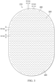
- Figure 3 is a schematic view of an example of the second layer 210, illustrating additional details that may be associated with some embodiments.
- the fluid restrictions 220 may each consist essentially of one or more linear slots having a length of about 3 millimeters.
- Figure 3 additionally illustrates an example of a uniform distribution pattern of the fluid restrictions 220.
- the fluid restrictions 220 are substantially coextensive with the second layer 210, and are distributed across the second layer 210 in a grid of parallel rows and columns, in which the slots are also mutually parallel to each other.
- the rows may be spaced about 3 millimeters on center, and the fluid restrictions 220 within each of the rows may be spaced about 3 millimeters on center as illustrated in the example of Figure 3 .
- the fluid restrictions 220 in adjacent rows may be aligned or offset.
- adjacent rows may be offset, as illustrated in Figure 3 , so that the fluid restrictions 220 are aligned in alternating rows and separated by about 6 millimeters.
- the spacing of the fluid restrictions 220 may vary in some embodiments to increase the density of the fluid restrictions 220 according to therapeutic requirements.
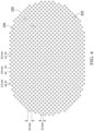
- Figure 4 is a schematic view of an example configuration of the apertures 235, illustrating additional details that may be associated with some embodiments of the third layer 215.
- the apertures 235 illustrated in Figure 4 may be associated only with the interior portion 230.
- the apertures 235 are generally circular and have a diameter of about 2 millimeters.
- Figure 4 also illustrates an example of a uniform distribution pattern of the apertures 235 in the interior portion 230.
- the apertures 235 are distributed across the interior portion 230 in a grid of parallel rows and columns. Within each row and column, the apertures 235 may be equidistant from each other, as illustrated in the example of Figure 4.
- Figure 4 illustrates one example configuration that may be particularly suitable for many applications, in which the apertures 235 are spaced about 6 millimeters apart along each row and column, with a 3 millimeter offset.
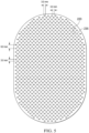
- Figure 5 is a schematic view of the example third layer 215 of Figure 4 overlaid on the second layer 210 of Figure 3 , illustrating additional details that may be associated with some example embodiments of the tissue interface 114.
- the fluid restrictions 220 may be aligned, overlapping, in registration with, or otherwise fluidly coupled to the apertures 235 in some embodiments.
- one or more of the fluid restrictions 220 may be registered with the apertures 235 only in the interior portion 230, or only partially registered with the apertures 235.
- the fluid restrictions 220 in the example of Figure 5 are generally configured so that each of the fluid restrictions 220 is registered with only one of the apertures 235.
- one or more of the fluid restrictions 220 may be registered with more than one of the apertures 235.
- any one or more of the fluid restrictions 220 may be a perforation or a fenestration that extends across two or more of the apertures 235. Additionally or alternatively, one or more of the fluid restrictions 220 may not be registered with any of the apertures 235.
- the apertures 235 may be sized to expose a portion of the second layer 210, the fluid restrictions 220, or both through the third layer 215.
- each of the apertures 235 may be sized to expose no more than two of the fluid restrictions 220.
- the length of each of the fluid restrictions 220 may be substantially equal to or less than the diameter of each of the apertures 235.
- the average dimensions of the fluid restrictions 220 are substantially similar to the average dimensions of the apertures 235.
- the apertures 235 may be elliptical in some embodiments, and the length of each of the fluid restrictions 220 may be substantially equal to the major axis or the minor axis. In some embodiments, though, the dimensions of the fluid restrictions 220 may exceed the dimensions of the apertures 235, and the size of the apertures 235 may limit the effective size of the fluid restrictions 220 exposed to the lower surface of the dressing 104.
- the first layer 205 may be a foam, mesh, or non-woven coated with an antimicrobial agent.
- the first layer may comprise antimicrobial elements, such as fibers coated with an antimicrobial agent.
- some embodiments of the second layer 210 may be a polymer coated or mixed with an antimicrobial agent.
- the fluid conductor 265 may additionally or alternatively be treated with one or more antimicrobial agents.
- Suitable antimicrobial agents may include, for example, metallic silver, PHMB, iodine or its complexes and mixes such as povidone iodine, copper metal compounds, chlorhexidine, or some combination of these materials.
- Individual components of the dressing 104 may be bonded or otherwise secured to one another with a solvent or non-solvent adhesive, or with thermal welding, for example, without adversely affecting fluid management.
- the second layer 210 or the first layer 205 may be coupled to the border 250 of the third layer 215 in any suitable manner, such as with a weld or an adhesive, for example.
- the cover 116, the first layer 205, the second layer 210, the third layer 215, or various combinations may be assembled before application or in situ.
- the cover 116 may be laminated to the first layer 205, and the second layer 210 may be laminated to the first layer 205 opposite the cover 116 in some embodiments.
- the third layer 215 may also be coupled to the second layer 210 opposite the first layer 205 in some embodiments.
- one or more layers of the tissue interface 114 may coextensive.
- the first layer 205 may be coextensive with the second layer 210, as illustrated in the embodiment of Figure 2 .
- the dressing 104 may be provided as a single, composite dressing.
- the third layer 215 may be coupled to the cover 116 to enclose the first layer 205 and the second layer 210, wherein the third layer 215 is configured to face a tissue site.
- the release liner 260 may be removed to expose the third layer 215, which may be placed within, over, on, or otherwise proximate to a tissue site, particularly a surface tissue site and adjacent epidermis.
- the third layer 215 and the second layer 210 may be interposed between the first layer 205 and the tissue site, which can substantially reduce or eliminate adverse interaction with the first layer 205.
- the third layer 215 may be placed over a surface wound (including edges of the wound) and undamaged epidermis to prevent direct contact with the first layer 205.
- Treatment of a surface wound or placement of the dressing 104 on a surface wound includes placing the dressing 104 immediately adjacent to the surface of the body or extending over at least a portion of the surface of the body.
- Treatment of a surface wound does not include placing the dressing 104 wholly within the body or wholly under the surface of the body, such as placing a dressing within an abdominal cavity.
- the interior portion 230 of the third layer 215 may be positioned adjacent to, proximate to, or covering a tissue site.
- at least some portion of the second layer 210, the fluid restrictions 220, or both may be exposed to a tissue site through the third layer 215.
- the periphery 225 of the third layer 215 may be positioned adjacent to or proximate to tissue around or surrounding the tissue site.
- the third layer 215 may be sufficiently tacky to hold the dressing 104 in position, while also allowing the dressing 104 to be removed or re-positioned without trauma to the tissue site.
- Removing the release liner 260 can also expose the adhesive 255, and the cover 116 may be attached to an attachment surface.
- the cover may be attached to epidermis peripheral to a tissue site, around the first layer 205 and the second layer 210.
- the adhesive 255 may be in fluid communication with an attachment surface through the apertures 235 in at least the periphery 225 of the third layer 215 in some embodiments.
- the adhesive 255 may also be in fluid communication with the edges 245 through the apertures 235 exposed at the edges 245.
- the adhesive 255 may be pressed through the apertures 235 to bond the dressing 104 to the attachment surface.
- the apertures 235 at the edges 245 may permit the adhesive 255 to flow around the edges 245 for enhancing the adhesion of the edges 159 to an attachment surface.
- apertures or holes in the third layer 215 may be sized to control the amount of the adhesive 255 in fluid communication with the apertures 235.
- the relative sizes of the apertures 235 may be configured to maximize the surface area of the adhesive 255 exposed and in fluid communication through the apertures 235 at the corners 240.
- the edges 245 may intersect at substantially a right angle, or about 90 degrees, to define the corners 240.
- the corners 240 may have a radius of about 10 millimeters.
- three of the apertures 235 having a diameter between about 7.75 millimeters to about 8.75 millimeters may be positioned in a triangular configuration at the corners 240 to maximize the exposed surface area for the adhesive 255.
- the size and number of the apertures 235 in the corners 240 may be adjusted as necessary, depending on the chosen geometry of the corners 240, to maximize the exposed surface area of the adhesive 255.
- the apertures 235 at the corners 240 may be fully housed within the third layer 215, substantially precluding fluid communication in a lateral direction exterior to the corners 240.
- the apertures 235 at the corners 240 being fully housed within the third layer 215 may substantially preclude fluid communication of the adhesive 255 exterior to the corners 240, and may provide improved handling of the dressing 104 during deployment at a tissue site. Further, the exterior of the corners 240 being substantially free of the adhesive 136 may increase the flexibility of the corners 240 to enhance comfort.
- the bond strength of the adhesive 255 may vary in different locations of the dressing 104.
- the adhesive 255 may have a lower bond strength in locations adjacent to the third layer 215 where the apertures 235 are relatively larger, and may have a higher bond strength where the apertures 235 are smaller.
- Adhesive 255 with lower bond strength in combination with larger apertures 235 may provide a bond comparable to adhesive 255 with higher bond strength in locations having smaller apertures 235.
- the geometry and dimensions of the tissue interface 114, the cover 116, or both may vary to suit a particular application or anatomy.
- the geometry or dimensions of the tissue interface 114 and the cover 116 may be adapted to provide an effective and reliable seal against challenging anatomical surfaces, such as an elbow or heel, at and around a tissue site.
- the dimensions may be modified to increase the surface area for the third layer 215 to enhance the movement and proliferation of epithelial cells at a tissue site and reduce the likelihood of granulation tissue in-growth.
- the dressing 104 may permit re-application or re-positioning to reduce or eliminate leaks, which can be caused by creases and other discontinuities in the dressing 104 and a tissue site.
- the ability to rectify leaks may increase the reliability of the therapy and reduce power consumption in some embodiments.
- the dressing 104 in the example of Figure 2 can provide a sealed therapeutic environment proximate to a tissue site, substantially isolated from the external environment, and the negative-pressure source 102 can reduce the pressure in the sealed therapeutic environment.
- the third layer 215 may provide an effective and reliable seal against challenging anatomical surfaces, such as an elbow or heel, at and around a tissue site.
- the dressing 104 may permit re-application or re-positioning, to correct air leaks caused by creases and other discontinuities in the dressing 104, for example.
- the ability to rectify leaks may increase the efficacy of the therapy and reduce power consumption in some embodiments.
- the dressing interface 270 may disposed over the aperture 275 and attached to the cover 116.
- the fluid conductor 265 may be fluidly coupled to the dressing interface 270 and to the negative-pressure source 102.
- Negative pressure applied through the tissue interface 114 can create a negative pressure differential across the fluid restrictions 220 in the second layer 210, which can open or expand the fluid restrictions 220 from their resting state.
- the fluid restrictions 220 may comprise substantially closed fenestrations through the second layer 210
- a pressure gradient across the fenestrations can strain the adjacent material of the second layer 210 and increase the dimensions of the fenestrations to allow liquid movement through them, similar to the operation of a duckbill valve. Opening the fluid restrictions 220 can allow exudate and other liquid movement through the fluid restrictions 220 into the first layer 205 and the container 106.
- Changes in pressure can also cause the first layer 205 to expand and contract, and the interior border 250 may protect the epidermis from irritation.
- the second layer 210 and the third layer 215 can also substantially reduce or prevent exposure of tissue to the first layer 205, which can inhibit growth of tissue into the first layer 205.
- the first layer 205 may be hydrophobic to minimize retention or storage of liquid in the dressing 104. In other embodiments, the first layer 205 may be hydrophilic. In an example in which the first layer 205 may be hydrophilic, the first layer 205 may also wick fluid away from a tissue site, while continuing to distribute negative pressure to the tissue site. The wicking properties of the first layer 205 may draw fluid away from a tissue site by capillary flow or other wicking mechanisms, for example.
- An example of a hydrophilic first layer 205 is a polyvinyl alcohol, open-cell foam such as V.A.C. WHITEFOAM TM dressing available from KCI of San Antonio, Texas. Other hydrophilic foams may include those made from polyether. Other foams that may exhibit hydrophilic characteristics include hydrophobic foams that have been treated or coated to provide hydrophilicity.
- the pressure differential across the fluid restrictions 220 can dissipate, allowing the fluid restrictions 220 to move to their resting state and prevent or reduce the rate at which exudate or other liquid from returning to the tissue site through the second layer 210.
- a filler may also be disposed between a tissue site and the third layer 215.
- a wound filler may be applied interior to the periwound, and the third layer 215 may be disposed over the peri wound and the wound filler.
- the filler may be a manifold, such as an open-cell foam.
- the filler may comprise or consist essentially of the same material as the first layer 205 in some embodiments.
- instillation solution or other fluid may be distributed to the dressing 104, which can increase the pressure in the tissue interface 114.
- the increased pressure in the tissue interface 114 can create a positive pressure differential across the fluid restrictions 220 in the second layer 210, which can open or expand the fluid restrictions 220 from their resting state to allow the instillation solution or other fluid to be distributed to the tissue site.
- FIG. 6 is a schematic view of another example of the third layer 215, illustrating additional details that may be associated with some embodiments.
- the third layer 215 may have one or more fluid restrictions, such as valves 605, instead of or in addition to the apertures 235 in the interior portion 230.
- the valves 605 may be included in the third layer 215 in addition to or instead of the fluid restrictions 220 in the second layer 210.
- the second layer 210 may be omitted.
- the tissue interface 114 may consist essentially of the first layer 205 and the third layer 215 of Figure 6 with the valves 605 disposed in the interior portion 230.
- FIG. 7 and Figure 8 illustrate other example configurations of the valves 605, in which the valves 605 each generally comprise a combination of intersecting slits or cross-slits.
- Methods of treating a surface wound not according to the invention to promote healing and tissue granulation may include applying the dressing 104 to a surface wound and sealing the dressing 104 to epidermis adjacent to the surface wound.
- the third layer 215 may be placed over the surface wound, covering at least a portion of the edge of the surface wound and a periwound adjacent to the surface wound.
- the cover may also be attached to epidermis around the third layer 215.
- the dressing 104 may be fluidly coupled to a negative-pressure source, such as the negative-pressure source 102. Negative pressure from the negative-pressure source may be applied to the dressing 104, opening the fluid restrictions 220.
- the fluid restrictions 220 can be closed by blocking, stopping, or reducing the negative pressure.
- the second layer 210 and the third layer 215 can substantially prevent exposure of tissue in the surface wound to the first layer 205, inhibiting growth of tissue into the first layer 205.
- the dressing 104 can also substantially prevent maceration of the peri wound.
- the systems, apparatuses, and methods described herein may provide significant advantages over prior dressings.
- some dressings for negative-pressure therapy can require time and skill to be properly sized and applied to achieve a good fit and seal.
- some embodiments of the dressing 104 provide a negative-pressure dressing that is simple to apply, reducing the time to apply and remove.
- the dressing 104 may be a fully-integrated negative-pressure therapy dressing that can be applied to a tissue site (including on the periwound) in one step, without being cut to size, while still providing or improving many benefits of other negative-pressure therapy dressings that require sizing.
- Such benefits may include good manifolding, beneficial granulation, protection of the peripheral tissue from maceration, and a low-trauma and high-seal bond. These characteristics may be particularly advantageous for surface wounds having moderate depth and medium-to-high levels of exudate.
- Some embodiments of the dressing 104 may remain on the tissue site for at least 5 days, and some embodiments may remain for at least 7 days.
- Antimicrobial agents in the dressing 104 may extend the usable life of the dressing 104 by reducing or eliminating infection risks that may be associated with extended use, particularly use with infected or highly exuding wounds.
- the primary objective of this study was to evaluate an embodiment of a dressing having features described above (designated as "GM” for purposes of the study), in conjunction with V.A.C. ® Therapy and V.A.C. VERAFLO TM Therapy as compared to traditional V.A.C. ® Therapy with GRANUFOAM TM dressing and to other Advanced Wound Care dressings without V.A.C. ® Therapy.
- Wounds were assessed for granulation tissue formation, presence of maceration in periwound skin and ease of dressing removal as determined by:
- Treatment Regimens and Dressings Therapy/Treatment Number Treatment Abbreviation Test Material Therapy 1 TANPT a TA Continuous V.A.C. ® Therapy 2 TANPTI a TA V.A.C. VERAFLO TM with saline 3 NPT CA1 Continuous V.A.C. ® Therapy 4 AWD CA2 None 5 NPTI CA3 V.A.C. VERAFLO TM with saline a With conductive wires placed on top on intact skin under dressing as appropriate
- the initial pilot animal (Group 1) underwent all wound creation and therapy prior to scheduling procedures on the additional Group 2 and 3 animals.
- Up to Ten (10) full thickness skin excisional wounds ( ⁇ 3 ⁇ 7.5 cm) were created on each animal (up to 5 wounds on each side of the spine) with the aid of a sterile template. There was spacing between each of the wounds (approximately 6 cm or more from wound edge to wound edge between adjacent wounds, and sufficient spacing between all wounds to provide enough space to properly place the dressings and the drape. If the length of the back of the animal did not provide enough space for 10 wounds and dressings (determined on Day 0) then 8 wounds (4 on each side of spine) was created.
- a scalpel blade was used to surgically create the wound down to the subcutaneous fascial layer (just over the muscle) but without disrupting it. If disruption of the subcutaneous fascial layer occurred, it was documented in the study records. Care was taken during wound creation so as not to undermine the perimeter of the wound.
- the wounds were prepared in two paraspinal columns with efforts made to keep the columns between the crest of the shoulders and the coccygeal tuberosity. Direct pressure with sterile gauze was utilized to obtain hemostasis. In the event of excessive bleeding that did not subside with direct pressure, a hemostat was used to clamp the source of bleeding. Wound sites were kept moist with sterile 0.9% saline-soaked gauze during the creation of other wounds. Wounds were photographed.
- the peri wound area was wiped clean with sterile 0.9% saline-soaked gauze and allowed to dry. Dressings were applied to the individual wound sites per a randomization scheme.
- An adhesive such as benzoin was placed on the skin surrounding the very perimeter of the test article edges, regardless of the type of dressing for a particular wound, so that the peri wound area was framed with adhesive leaving a ⁇ 1cm perimeter of peri wound free of benzoin. This means that the immediate periwound skin cannot have benzoin adhesive applied as this may affect the EpiD readings.
- the adhesive was placed on the skin in any area that V.A.C. ® Drape was applied.
- Hollister a medical grade silicone adhesive was applied as an extra adhesive to help maintain a seal.
- test article wound pair test article with V.A.C. ® Therapy
- test article with V.A.C. VERAFLO TM Therapy test article using V.A.C. VERAFLO TM Therapy with saline
- a pair of electrodes e.g. aluminum sheet or wire
- V.A.C. ® Drape As applicable, the skin underneath the strips of the foam bridge were covered with V.A.C. ® Drape to protect it. Each bridged wound group was covered with the V.A.C. ® Drape included in the dressing kit, one hole will be made in the drape , and a SENSAT.R.A.C. TM Pad or a V.A.C. VERAT.R.A.C. TM Pad (as applicable) was attached directly above the hole as per instructions for use (IFU). Each of the pads was framed with V.A.C. ® Drape along each side to keep it in place and to make sure there was a seal.
- V.A.C.ULTA TM unit was present in the surgical suite on the day of wound creation and was appropriately connected to each pad to verify that each wound group had been sealed properly following the application.
- negative-pressure wound therapy began at a continuous vacuum pressure of -125 mmHg using the SEAL CHECK TM function on the V.A.C.ULTA TM Unit.
- the V.A.C.ULTA TM unit was turned off and this procedure was repeated as applicable.
- additional layers of V.A.C. ® Drape was placed around the edges to reinforce the seals and prevent leaks.
- V.A.C. VERAFLO TM Therapy NPWT was begun at a continuous vacuum pressure of -125 mmHg using the SEAL CHECK TM function on the V.A.C.ULTA TM Unit. Upon verification of a proper seal, the V.A.C.ULTA TM unit was turned off and this procedure was repeated as applicable. Following verification of all seals, additional layers of V.A.C. ® Drape were placed around the edges to reinforce the seals and prevent leaks. The soak/dwell time per cycle was 10 minutes, NPWT time per cycle was 3.5 hours with a target pressure of -125 mmHg.
- V.A.C. ® Drape-covered area was draped with a tear-resistant mesh (e.g. organza material) secured with V.A.C. ® Drape, Elastikon ® or equivalent to prevent dislodgement of the dressings.
- a tear-resistant mesh e.g. organza material
- Peel force testing was performed on one wound from each treatment pair (same wounds as dressing change, if applicable). For wounds where the dressing had been removed, TEWL was performed, wound assessments were performed and photographs taken.
- Peel force testing was performed on a tilting operating table.
- the peel force test was performed using a device that peels back the test material edge while measuring the force that is required to peel the dressing from the wound at an angle of ⁇ 180° relative to the peel tester.
- a digital protractor was used to confirm the angle.
- the peel strength values indicate the ease with which the test materials can be removed from the wound bed. Removal of the test materials was performed using a 20N Shimpo Digital Force Gauge that was mounted onto a Shimpo Motorized Test Stand and controlled via a computer equipped with LabView.
- the drape over the control articles for peel testing was gently circumscribed with a scalpel, taking care to not disrupt the tissue ingrowth into the sides of the dressing.
- a scalpel was used to remove the excess dressing that was not in contact with the wound. This was done by cutting the dressing along the sides, bottom and top where the margins of the wound are visible after negative pressure therapy.
- the medial end of the dressing or dressing tab was attached to the force gauge with the clip (no circumscribing of the dressing will be performed).
- the dressing was then pulled from the wound (medial to lateral) at a constant rate from a medial to lateral direction. After the peel force measurements were taken, assessments were performed. Continuous peel force readings were recorded through LabView via the Force Gauge and saved for each wound. Following peel testing, the dressings were saved for analysis of the tissue that remains within the dressing.
- Fig. 9 demonstrates the results of maximum peel force measurements (N) on day 7 following dressing application and removal of test articles (designated as "TANPT” and TANPTI) and control dressings. As can be seen, the test article with and without V.A.C. VERAFLO TM Therapy required significantly less peel force.
- Determination of the level of moisture at the dressing-skin (intact) interface was performed using a Moisture Meter the EpiD Compact from Delfin Technologies (Kuopio, Finland). This measurement was done immediately after wound creation on Day 0, at the dressing change day (as applicable), and at termination prior to euthanasia. To measure the dielectric constant of the skin, the EpiD Compact instrument was turned used. On the day of wound creation (Day 0), four consecutive measurements of moisture was collected from intact skin on each animal approximating midway between the wound and edge of the wound pad of where the test article and the advanced wound dressings were. On dressing change day and at termination (as applicable), four consecutive measurements of moisture were collected. These measurements were repeated on each of the available wound sites for each animal. All of the measurements/data was recorded.
- Dressing retention (small particles and large pieces) was assessed following dressing removal or peel testing. After removal of the dressings from the wound, dressing retention in the wound was visually assessed and documented. All removed dressings was visually assessed for tissue retention and digitally photographed.
- Figure 10 demonstrates that there was a significant reduction in tissue ingrowth with TANPT and TANPTI.
- wound sites were in 70% ethanol they were immediately processed and if received in NBF wounds were transferred to 70% ethanol for a period of time before further processing per Histopathology Test Site standard procedures.
- the wound site + dressings (if intact), were embedded in oversized paraffin blocks, entire en bloc site was cross sectioned once at ⁇ 5 ⁇ m thickness and resulting slides stained with Hematoxylin and Eosin (H&E). Gross images were taken of the cut surface of the specimens prior to processing and embedding in paraffin. In order to accommodate the entire tissue section with border of non-affected skin on all sides, oversized slides were used.
- Microscopic evaluation of all stained sections for morphological changes for the wound including, but not limited to, granulation tissue thickness and character, amount of granulation tissue embedded in dressing (if possible), tissue inflammation, edema, vascularity (if possible), presence of bacteria, necrosis and other relevant factors as determined by the pathologist.
- the peri-wound area was evaluated for characteristics consistent with maceration as determined by the pathologist.
- FIG. 12 is a graphical representation comparing the Day 7 granulation tissue thickness between the test and control treatments. TANPT and TANPTI showed significantly higher granulation tissue thickness.
- test article had surprisingly positive results, with improvement when combined with V.A.C. VERAFLO TM Therapy.
- the test article with V.A.C. VERAFLO TM Therapy performed superiorly by showing an increase in granulation tissue thickness, a reduction in tissue ingrowth, percent epithelialization and average vascularization score.
- one or more of the features of some layers may be combined with features of other layers to provide an equivalent function.
- one or more of the fluid restrictions 220 may have shapes similar to shapes described as exemplary for the valves 605.
- Components may be also be combined or eliminated in various configurations for purposes of sale, manufacture, assembly, or use.
- the dressing 104, the container 106, or both may be eliminated or separated from other components for manufacture or sale.
- the controller 108 may also be manufactured, configured, assembled, or sold independently of other components.
Description
- The invention set forth in the appended claims relates generally to tissue treatment systems and more particularly, but without limitation, to dressings for tissue treatment with negative pressure.
- Clinical studies and practice have shown that reducing pressure in proximity to a tissue site can augment and accelerate growth of new tissue at the tissue site. The applications of this phenomenon are numerous, but it has proven particularly advantageous for treating wounds. Regardless of the etiology of a wound, whether trauma, surgery, or another cause, proper care of the wound is important to the outcome. Treatment of wounds or other tissue with reduced pressure may be commonly referred to as "negative-pressure therapy," but is also known by other names, including "negative-pressure wound therapy," "reduced-pressure therapy," "vacuum therapy," "vacuum-assisted closure," and "topical negative-pressure," for example. Negative-pressure therapy may provide a number of benefits, including migration of epithelial and subcutaneous tissues, improved blood flow, and micro-deformation of tissue at a wound site. Together, these benefits can increase development of granulation tissue and reduce healing times.
-
WO 01/85248 A1 WO 2016/015001 A2 descibe dressings that can be used with negative pressure, - While the clinical benefits of negative-pressure therapy are widely known, improvements to therapy systems, components, and processes may benefit healthcare providers and patients.
- The invention is defined by the claims in which there is required a dressing for treating a tissue site with negative pressure, the dressing comprising: a first layer comprising a polymer film having a plurality of fluid restrictions through the polymer film that are configured to expand in response to a pressure gradient across the polymer film; a second layer coupled to the first layer, the second layer comprising a manifold; a third layer coupled to the second layer opposite the first layer, the third layer comprising a polymer drape; and a fourth layer coupled to the first layer opposite the second layer, the fourth layer comprising a hydrophobic gel having a plurality of apertures.
A selection of optional features is set out in the dependent claims. - Insofar as the term invention or embodiment is used in the following, or features are presented as being optional, this should be interpreted in such a way that the only protection sought is that of the invention claimed.
- Reference(s) to "embodiment(s)" throughout the description which are not under the scope of the appended claims merely represent possible exemplary executions and are not part of the present invention.
-
-
Figure 1 is a functional block diagram of an example embodiment of a therapy system that can provide tissue treatment in accordance with this specification; -
Figure 2 is an assembly view of an example of a dressing, illustrating additional details that may be associated with some example embodiments of the therapy system ofFigure 1 ; -
Figure 3 is a schematic view of an example configuration of fluid restrictions in a layer that may be associated with some embodiments of the dressing ofFigure 2 ; -
Figure 4 is a schematic view of an example configuration of apertures in another layer, illustrating additional details that may be associated with some embodiments of the dressing ofFigure 2 ; -
Figure 5 is a schematic view of the example layer ofFigure 4 overlaid on the example layer ofFigure 3 ; -
Figure 6 is a schematic view of another example of another dressing layer, illustrating additional details that may be associated with some embodiments; -
Figure 7 andFigure 8 illustrate other example configurations of fluid restrictions that may be associated with some embodiments of layers of the dressing ofFigure 2 ; -
Figure 9 is a graphical representation of maximum peel force measurements (N) onday 7 following dressing application and removal of each test and control dressing; -
Figure 10 is a graphical representation of tissue ingrowth measurements. Thickness (mm) is measured for each test and control dressing; -
Figure 11 is an optical micrograph picture demonstrating granulation tissue thickness for each test and control dressing; and -
Figure 12 is a graphical representation ofFigure 11 demonstrating quantitative morphometry granulation tissue thickness for each test and control dressing. - The following description of example embodiments provides information that enables a person skilled in the art to make and use the subject matter set forth in the appended claims, and may omit certain details already well-known in the art. The following detailed description is, therefore, to be taken as illustrative and not limiting.
- The example embodiments may also be described herein with reference to spatial relationships between various elements or to the spatial orientation of various elements depicted in the attached drawings. In general, such relationships or orientation assume a frame of reference consistent with or relative to a patient in a position to receive treatment. However, as should be recognized by those skilled in the art, this frame of reference is merely a descriptive expedient rather than a strict prescription.
-
Figure 1 is a simplified functional block diagram of an example embodiment of atherapy system 100 that can provide negative-pressure therapy with instillation of topical treatment solutions to a tissue site in accordance with this specification. - The term "tissue site" in this context broadly refers to a wound, defect, or other treatment target located on or within tissue, including but not limited to, a surface wound, bone tissue, adipose tissue, muscle tissue, neural tissue, dermal tissue, vascular tissue, connective tissue, cartilage, tendons, or ligaments. The term "tissue site" may also refer to areas of any tissue that are not necessarily wounded or defective, but are instead areas in which it may be desirable to add or promote the growth of additional tissue. For example, negative pressure may be applied to a tissue site to grow additional tissue that may be harvested and transplanted. A surface wound, as used herein, is a wound on the surface of a body that is exposed to the outer surface of the body, such an injury or damage to the epidermis, dermis, and/or subcutaneous layers. Surface wounds may include ulcers or closed incisions, for example. A surface wound, as used herein, does not include wounds within an intra-abdominal cavity. A wound may include chronic, acute, traumatic, subacute, and dehisced wounds, partial-thickness burns, ulcers (such as diabetic, pressure, or venous insufficiency ulcers), flaps, and grafts, for example.
- The
therapy system 100 may include a source or supply of negative pressure, such as a negative-pressure source 102, adressing 104, a fluid container, such as acontainer 106, and a regulator or controller, such as acontroller 108, for example. Additionally, thetherapy system 100 may include sensors to measure operating parameters and provide feedback signals to thecontroller 108 indicative of the operating parameters. As illustrated inFigure 1 , for example, thetherapy system 100 may include apressure sensor 110, anelectric sensor 112, or both, coupled to thecontroller 108. As illustrated in the example ofFigure 1 , thedressing 104 may comprise or consist essentially of one or more dressing layers, such as atissue interface 114, acover 116, or both in some embodiments. - The
therapy system 100 may also include a source of instillation solution. For example, asolution source 118 may be fluidly coupled to thedressing 104, as illustrated in the example embodiment ofFigure 1 . Thesolution source 118 may be fluidly coupled to a positive-pressure source such as the positive-pressure source 120, a negative-pressure source such as the negative-pressure source 102, or both in some embodiments. A regulator, such as aninstillation regulator 122, may also be fluidly coupled to thesolution source 118 and thedressing 104 to ensure proper dosage of instillation solution (e.g. saline) to a tissue site. For example, theinstillation regulator 122 may comprise a piston that can be pneumatically actuated by the negative-pressure source 102 to draw instillation solution from the solution source during a negative-pressure interval and to instill the solution to a dressing during a venting interval. Additionally or alternatively, thecontroller 108 may be coupled to the negative-pressure source 102, the positive-pressure source 120, or both, to control dosage of instillation solution to a tissue site. In some embodiments, theinstillation regulator 122 may also be fluidly coupled to the negative-pressure source 102 through thedressing 104, as illustrated in the example ofFigure 1 . - Some components of the
therapy system 100 may be housed within or used in conjunction with other components, such as sensors, processing units, alarm indicators, memory, databases, software, display devices, or user interfaces that further facilitate therapy. For example, in some embodiments, the negative-pressure source 102 may be combined with thesolution source 118, thecontroller 108 and other components into a therapy unit. - In general, components of the
therapy system 100 may be coupled directly or indirectly. For example, the negative-pressure source 102 may be directly coupled to thecontainer 106, and may be indirectly coupled to thedressing 104 through thecontainer 106. Coupling may include fluid, mechanical, thermal, electrical, or chemical coupling (such as a chemical bond), or some combination of coupling in some contexts. For example, the negative-pressure source 102 may be electrically coupled to thecontroller 108. The negative-pressure source maybe fluidly coupled to one or more distribution components, which provide a fluid path to a tissue site. In some embodiments, components may also be coupled by virtue of physical proximity, being integral to a single structure, or being formed from the same piece of material. - A distribution component is preferably detachable, and may be disposable, reusable, or recyclable. The
dressing 104 and thecontainer 106 are illustrative of distribution components. A fluid conductor is another illustrative example of a distribution component. A "fluid conductor," in this context, broadly includes a tube, pipe, hose, conduit, or other structure with one or more lumina or open pathways adapted to convey a fluid between two ends. Typically, a tube is an elongated, cylindrical structure with some flexibility, but the geometry and rigidity may vary. Moreover, some fluid conductors may be molded into or otherwise integrally combined with other components. Distribution components may also include or comprise interfaces or fluid ports to facilitate coupling and de-coupling other components, including sensors and data communication devices. In some embodiments, for example, a dressing interface may facilitate coupling a fluid conductor to thedressing 104. For example, such a dressing interface may be a SENSAT.R.A.C.™ Pad available from KCI of San Antonio, Texas. - A negative-pressure supply, such as the negative-
pressure source 102, may be a reservoir of air at a negative pressure, or may be a manual or electrically-powered device, such as a vacuum pump, a suction pump, a wall suction port available at many healthcare facilities, or a micro-pump, for example. "Negative pressure" generally refers to a pressure less than a local ambient pressure, such as the ambient pressure in a local environment external to a sealed therapeutic environment. In many cases, the local ambient pressure may also be the atmospheric pressure at which a tissue site is located. Alternatively, the pressure may be less than a hydrostatic pressure associated with tissue at the tissue site. Unless otherwise indicated, values of pressure stated herein are gauge pressures. References to increases in negative pressure typically refer to a decrease in absolute pressure, while decreases in negative pressure typically refer to an increase in absolute pressure. While the amount and nature of negative pressure applied to a tissue site may vary according to therapeutic requirements, the pressure is generally a low vacuum, also commonly referred to as a rough vacuum, between -5 mm Hg (-667 Pa) and -500 mm Hg (-66.7 kPa). Common therapeutic ranges are between -50 mm Hg (-9.9 kPa) and -300 mm Hg (-39.9 kPa). - The
container 106 is representative of a container, canister, pouch, or other storage component, which can be used to manage exudates and other fluids withdrawn from a tissue site. In many environments, a rigid container may be preferred or required for collecting, storing, and disposing of fluids. In other environments, fluids may be properly disposed of without rigid container storage, and a re-usable container could reduce waste and costs associated with negative-pressure therapy. - A controller, such as the
controller 108, may be a microprocessor or computer programmed to operate one or more components of thetherapy system 100, such as the negative-pressure source 102. In some embodiments, for example, thecontroller 108 may be a microcontroller, which generally comprises an integrated circuit containing a processor core and a memory programmed to directly or indirectly control one or more operating parameters of thetherapy system 100. Operating parameters may include the power applied to the negative-pressure source 102, the pressure generated by the negative-pressure source 102, or the pressure distributed to thetissue interface 114, for example. Thecontroller 108 is also preferably configured to receive one or more input signals, such as a feedback signal, and programmed to modify one or more operating parameters based on the input signals. - Sensors, such as the
pressure sensor 110 or theelectric sensor 112, are generally known in the art as any apparatus operable to detect or measure a physical phenomenon or property, and generally provide a signal indicative of the phenomenon or property that is detected or measured. For example, thepressure sensor 110 and theelectric sensor 112 may be configured to measure one or more operating parameters of thetherapy system 100. In some embodiments, thepressure sensor 110 may be a transducer configured to measure pressure in a pneumatic pathway and convert the measurement to a signal indicative of the pressure measured. In some embodiments, for example, thepressure sensor 110 may be a piezo-resistive strain gauge. Theelectric sensor 112 may optionally measure operating parameters of the negative-pressure source 102, such as the voltage or current, in some embodiments. Preferably, the signals from thepressure sensor 110 and theelectric sensor 112 are suitable as an input signal to thecontroller 108, but some signal conditioning may be appropriate in some embodiments. For example, the signal may need to be filtered or amplified before it can be processed by thecontroller 108. Typically, the signal is an electrical signal, but may be represented in other forms, such as an optical signal. - The
tissue interface 114 can be generally adapted to contact a tissue site. Thetissue interface 114 may be partially or fully in contact with the tissue site. If the tissue site is a wound, for example, thetissue interface 114 may partially or completely fill the wound, or may be placed over the wound. Thetissue interface 114 may take many forms and have more than one layer in some embodiments. Thetissue interface 114 may also have many sizes, shapes, or thicknesses depending on a variety of factors, such as the type of treatment being implemented or the nature and size of a tissue site. For example, the size and shape of thetissue interface 114 may be adapted to the contours of deep and irregular shaped tissue sites. - In some embodiments, the
cover 116 may provide a bacterial barrier and protection from physical trauma. Thecover 116 may also be constructed from a material that can reduce evaporative losses and provide a fluid seal between two components or two environments, such as between a therapeutic environment and a local external environment. Thecover 116 may be, for example, an elastomeric film or membrane that can provide a seal adequate to maintain a negative pressure at a tissue site for a given negative-pressure source. Thecover 116 may have a high moisture-vapor transmission rate (MVTR) in some applications. For example, the MVTR may be at least 300 g/m^2 per twenty-four hours in some embodiments. In some example embodiments, thecover 116 may be a polymer drape, such as a polyurethane film, that is permeable to water vapor but impermeable to liquid. Such drapes typically have a thickness in the range of 25-50 microns. For permeable materials, the permeability generally should be low enough that a desired negative pressure may be maintained. Thecover 116 may comprise, for example, one or more of the following materials: hydrophilic polyurethane; cellulosics; hydrophilic polyamides; polyvinyl alcohol; polyvinyl pyrrolidone; hydrophilic acrylics; hydrophilic silicone elastomers; an INSPIRE 2301 material from Coveris Advanced Coatings of Wrexham, United Kingdom having, for example, an MVTR (inverted cup technique) of 14400 g/m2/24 hours and a thickness of about 30 microns; a thin, uncoated polymer drape; natural rubbers; polyisoprene; styrene butadiene rubber; chloroprene rubber; polybutadiene; nitrile rubber; butyl rubber; ethylene propylene rubber; ethylene propylene diene monomer; chlorosulfonated polyethylene; polysulfide rubber; polyurethane (PU); EVA film; co-polyester; silicones; a silicone drape; a 3M Tegaderm® drape; a polyurethane (PU) drape such as one available from Avery Dennison Corporation of Glendale, California; polyether block polyamide copolymer (PEBAX), for example, from Arkema, France; Inspire 2327; or other appropriate material. - An attachment device may be used to attach the
cover 116 to an attachment surface, such as undamaged epidermis, a gasket, or another cover. The attachment device may take many forms. For example, an attachment device may be a medically-acceptable, pressure-sensitive adhesive configured to bond thecover 116 to epidermis around a tissue site, such as a surface wound. In some embodiments, for example, some or all of thecover 116 may be coated with an adhesive, such as an acrylic adhesive, which may have a coating weight between 25-65 grams per square meter (g.s.m.). Thicker adhesives, or combinations of adhesives, may be applied in some embodiments to improve the seal and reduce leaks. Other example embodiments of an attachment device may include a double-sided tape, paste, hydrocolloid, hydrogel, silicone gel, or organogel. - The
solution source 118 may also be representative of a container, canister, pouch, bag, or other storage component, which can provide a solution for instillation therapy. Compositions of solutions may vary according to a prescribed therapy, but examples of solutions that may be suitable for some prescriptions include hypochlorite-based solutions, silver nitrate (0.5%), sulfur-based solutions, biguanides, cationic solutions, and isotonic solutions. - The fluid mechanics of using a negative-pressure source to reduce pressure in another component or location, such as within a sealed therapeutic environment, can be mathematically complex. However, the basic principles of fluid mechanics applicable to negative-pressure therapy and instillation are generally well-known to those skilled in the art, and the process of reducing pressure may be described illustratively herein as "delivering," "distributing," or "generating" negative pressure, for example.
- In general, exudates and other fluids flow toward lower pressure along a fluid path. Thus, the term "downstream" typically implies something in a fluid path relatively closer to a source of negative pressure or further away from a source of positive pressure. Conversely, the term "upstream" implies something relatively further away from a source of negative pressure or closer to a source of positive pressure. Similarly, it may be convenient to describe certain features in terms of fluid "inlet" or "outlet" in such a frame of reference. This orientation is generally presumed for purposes of describing various features and components herein. However, the fluid path may also be reversed in some applications (such as by substituting a positive-pressure source for a negative-pressure source) and this descriptive convention should not be construed as a limiting convention.
-
Figure 2 is an assembly view of an example of the dressing 104 ofFigure 1 , illustrating additional details that may be associated with some embodiments in which thetissue interface 114 comprises more than one layer. In the example ofFigure 2 , thetissue interface 114 comprises afirst layer 205, asecond layer 210, and athird layer 215. In some embodiments, thefirst layer 205 may be disposed adjacent to asecond layer 210, and thethird layer 215 may be disposed adjacent to thesecond layer 210 opposite thefirst layer 205. For example, thefirst layer 205, thesecond layer 210, and thethird layer 215 may be stacked so that thefirst layer 205 is in contact with thesecond layer 210, and thesecond layer 210 is in contact with thefirst layer 205 and thethird layer 215. One or more of thefirst layer 205, thesecond layer 210, and thethird layer 215 may also be bonded to an adjacent layer in some embodiments. - The
first layer 205 may comprise or consist essentially of a manifold or manifold layer, which provides a means for collecting or distributing fluid across thetissue interface 114 under pressure. For example, thefirst layer 205 may be adapted to receive negative pressure from a source and distribute negative pressure through multiple apertures across thetissue interface 114, which may have the effect of collecting fluid from across a tissue site and drawing the fluid toward the source. In some embodiments, the fluid path may be reversed or a secondary fluid path may be provided to facilitate delivering fluid, such as from a source of instillation solution, across thetissue interface 114. - In some illustrative embodiments, the
first layer 205 may comprise a plurality of pathways, which can be interconnected to improve distribution or collection of fluids. In some embodiments, thefirst layer 205 may comprise or consist essentially of a porous material having interconnected fluid pathways. For example, open-cell foam, reticulated foam, porous tissue collections, and other porous material such as gauze or felted mat generally include pores, edges, and/or walls adapted to form interconnected fluid channels. Liquids, gels, and other foams may also include or be cured to include apertures and fluid pathways. In some embodiments, thefirst layer 205 may additionally or alternatively comprise projections that form interconnected fluid pathways. For example, thefirst layer 205 may be molded to provide surface projections that define interconnected fluid pathways. Any or all of the surfaces of thefirst layer 205 may have an uneven, coarse, or jagged profile - In some embodiments, the
first layer 205 may comprise or consist essentially of a reticulated foam having pore sizes and free volume that may vary according to needs of a prescribed therapy. For example, a reticulated foam having a free volume of at least 90% may be suitable for many therapy applications, and a foam having an average pore size in a range of 400-600 microns (40-50 pores per inch) may be particularly suitable for some types of therapy. The tensile strength of thefirst layer 205 may also vary according to needs of a prescribed therapy. For example, the tensile strength of a foam may be increased for instillation of topical treatment solutions. The 25% compression load deflection of thefirst layer 205 may be at least 0.35 pounds per square inch, and the 65% compression load deflection may be at least 0.43 pounds per square inch. In some embodiments, the tensile strength of thefirst layer 205 may be at least 10 pounds per square inch. Thefirst layer 205 may have a tear strength of at least 2.5 pounds per inch. In some embodiments, thefirst layer 205 may be a foam comprised of polyols such as polyester or polyether, isocyanate such as toluene diisocyanate, and polymerization modifiers such as amines and tin compounds. In one non-limiting example, thefirst layer 205 may be a reticulated polyurethane ether foam such as used in GRANUFOAM™ dressing or V.A.C. VERAFLO™ dressing, both available from KCI of San Antonio, Texas. - The thickness of the
first layer 205 may also vary according to needs of a prescribed therapy. For example, the thickness of thefirst layer 205 may be decreased to relieve stress on other layers and to reduce tension on peripheral tissue. The thickness of thefirst layer 205 can also affect the conformability of thefirst layer 205. In some embodiments, a thickness in a range of about 5 millimeters to 10 millimeters may be suitable. - The
second layer 210 may comprise or consist essentially of a means for controlling or managing fluid flow. In some embodiments, the second layer may comprise or consist essentially of a liquid-impermeable, elastomeric material. For example, thesecond layer 210 may comprise or consist essentially of a polymer film. Thesecond layer 210 may also have a smooth or matte surface texture in some embodiments. A glossy or shiny finish better or equal to a grade B3 according to the SPI (Society of the Plastics Industry) standards may be particularly advantageous for some applications. In some embodiments, variations in surface height may be limited to acceptable tolerances. For example, the surface of the second layer may have a substantially flat surface, with height variations limited to 0.2 millimeters over a centimeter. - In some embodiments, the
second layer 210 may be hydrophobic. The hydrophobicity of thesecond layer 210 may vary, but may have a contact angle with water of at least ninety degrees in some embodiments. In some embodiments thesecond layer 210 may have a contact angle with water of no more than 150 degrees. For example, in some embodiments, the contact angle of thesecond layer 210 may be in a range of at least 90 degrees to about 120 degrees, or in a range of at least 120 degrees to 150 degrees. Water contact angles can be measured using any standard apparatus. Although manual goniometers can be used to visually approximate contact angles, contact angle measuring instruments can often include an integrated system involving a level stage, liquid dropper such as a syringe, camera, and software designed to calculate contact angles more accurately and precisely, among other things. Non-limiting examples of such integrated systems may include the FTÅ125, FTÅ200, FTÅ2000, and FTÅ4000 systems, all commercially available from First Ten Angstroms, Inc., of Portsmouth, VA, and the DTA25, DTA30, and DTA100 systems, all commercially available from Kruss GmbH of Hamburg, Germany. Unless otherwise specified, water contact angles herein are measured using deionized and distilled water on a level sample surface for a sessile drop added from a height of no more than 5 cm in air at 20-25°C and 20-50% relative humidity. Contact angles reported herein represent averages of 5-9 measured values, discarding both the highest and lowest measured values. The hydrophobicity of thesecond layer 210 may be further enhanced with a hydrophobic coating of other materials, such as silicones and fluorocarbons, either as coated from a liquid, or plasma coated. - The
second layer 210 may also be suitable for welding to other layers, including thefirst layer 205. For example, thesecond layer 210 may be adapted for welding to polyurethane foams using heat, radio frequency (RF) welding, or other methods to generate heat such as ultrasonic welding. RF welding may be particularly suitable for more polar materials, such as polyurethane, polyamides, polyesters and acrylates. Sacrificial polar interfaces may be used to facilitate RF welding of less polar film materials, such as polyethylene. - The area density of the
second layer 210 may vary according to a prescribed therapy or application. In some embodiments, an area density of less than 40 grams per square meter may be suitable, and an area density of about 20-30 grams per square meter may be particularly advantageous for some applications. - In some embodiments, for example, the
second layer 210 may comprise or consist essentially of a hydrophobic polymer, such as a polyethylene film. The simple and inert structure of polyethylene can provide a surface that interacts little, if any, with biological tissues and fluids, providing a surface that may encourage the free flow of liquids and low adherence, which can be particularly advantageous for many applications. More polar films suitable for laminating to a polyethylene film include polyamide, co-polyesters, ionomers, and acrylics. To aid in the bond between a polyethylene and polar film, tie layers may be used, such as ethylene vinyl acetate, or modified polyurethanes. An ethyl methyl acrylate (EMA) film may also have suitable hydrophobic and welding properties for some configurations. - As illustrated in the example of
Figure 2 , thesecond layer 210 may have one or morefluid restrictions 220, which can be distributed uniformly or randomly across thesecond layer 210. Thefluid restrictions 220 may be bi-directional and pressure-responsive. For example, thefluid restrictions 220 can generally comprise or consist essentially of an elastic passage that is normally unstrained to substantially reduce liquid flow, and can expand in response to a pressure gradient. In some embodiments, thefluid restrictions 220 may comprise or consist essentially of perforations in thesecond layer 210. Perforations may be formed by removing material from thesecond layer 210. For example, perforations may be formed by cutting through thesecond layer 210, which may also deform the edges of the perforations in some embodiments. In the absence of a pressure gradient across the perforations, the passages may be sufficiently small to form a seal or flow restriction, which can substantially reduce or prevent liquid flow. Additionally or alternatively, one or more of thefluid restrictions 220 may be an elastomeric valve that is normally closed when unstrained to substantially prevent liquid flow, and can open in response to a pressure gradient. A fenestration in thesecond layer 210 may be a suitable valve for some applications. Fenestrations may also be formed by removing material from thesecond layer 210, but the amount of material removed and the resulting dimensions of the fenestrations may be an order of magnitude less than perforations, and may not deform the edges. - For example, some embodiments of the
fluid restrictions 220 may comprise or consist essentially of one or more slots or combinations of slots in thesecond layer 210. In some examples, thefluid restrictions 220 may comprise or consist of linear slots having a length less than 4 millimeters and a width less than 1 millimeter. The length may be at least 2 millimeters, and the width may be at least 0.4 millimeters in some embodiments. A length of about 3 millimeters and a width of about 0.8 millimeter may be particularly suitable for many applications. A tolerance of about 0.1 millimeter may also be acceptable. Such dimensions and tolerances may be achieved with a laser cutter, for example. Slots of such configurations may function as imperfect valves that substantially reduce liquid flow in a normally closed or resting state. For example, such slots may form a flow restriction without being completely closed or sealed. The slots can expand or open wider in response to a pressure gradient to allow increased liquid flow. - The
third layer 215 may be a sealing layer comprising or consisting essentially of a soft, pliable material suitable for providing a fluid seal with a tissue site, and may have a substantially flat surface. For example, thethird layer 215 may comprise, without limitation, a silicone gel, a soft silicone, hydrocolloid, hydrogel, polyurethane gel, polyolefin gel, hydrogenated styrenic copolymer gel, a foamed gel, a soft closed cell foam such as polyurethanes and polyolefins coated with an adhesive, polyurethane, polyolefin, or hydrogenated styrenic copolymers. In some embodiments, thethird layer 215 may have a thickness between about 200 microns (µm) and about 1000 microns (µm). In some embodiments, thethird layer 215 may have a hardness between about 5 Shore OO and about 80 Shore OO. Further, thethird layer 215 may be comprised of hydrophobic or hydrophilic materials. - In some embodiments, the
third layer 215 may be a hydrophobic-coated material. For example, thethird layer 215 may be formed by coating a spaced material, such as, for example, woven, nonwoven, molded, or extruded mesh with a hydrophobic material. The hydrophobic material for the coating may be a soft silicone, for example. - The
third layer 215 may have aperiphery 225 surrounding or around aninterior portion 230, andapertures 235 disposed through theperiphery 225 and theinterior portion 230. Theinterior portion 230 may correspond to a surface area of thefirst layer 205 in some examples. Thethird layer 215 may also havecorners 240 and edges 245. Thecorners 240 and theedges 245 may be part of theperiphery 225. Thethird layer 215 may have aninterior border 250 around theinterior portion 230, disposed between theinterior portion 230 and theperiphery 225. Theinterior border 250 may be substantially free of theapertures 235, as illustrated in the example ofFigure 2 . In some examples, as illustrated inFigure 2 , theinterior portion 230 may be symmetrical and centrally disposed in thethird layer 215. - The
apertures 235 may be formed by cutting or by application of local RF or ultrasonic energy, for example, or by other suitable techniques for forming an opening. Theapertures 235 may have a uniform distribution pattern, or may be randomly distributed on thethird layer 215. Theapertures 235 in thethird layer 215 may have many shapes, including circles, squares, stars, ovals, polygons, slits, complex curves, rectilinear shapes, triangles, for example, or may have some combination of such shapes. - Each of the
apertures 235 may have uniform or similar geometric properties. For example, in some embodiments, each of theapertures 235 may be circular apertures, having substantially the same diameter. In some embodiments, the diameter of each of theapertures 235 may be between about 1 millimeter to about 50 millimeters. In other embodiments, the diameter of each of theapertures 235 may be between about 1 millimeter to about 20 millimeters. - In other embodiments, geometric properties of the
apertures 235 may vary. For example, the diameter of theapertures 235 may vary depending on the position of theapertures 235 in thethird layer 215, as illustrated inFigure2 . In some embodiments, the diameter of theapertures 235 in theperiphery 225 of thethird layer 215 may be larger than the diameter of theapertures 235 in theinterior portion 230 of thethird layer 215. For example, in some embodiments, theapertures 235 disposed in theperiphery 225 may have a diameter between about 9.8 millimeters to about 10.2 millimeters. In some embodiments, theapertures 235 disposed in thecorners 240 may have a diameter between about 7.75 millimeters to about 8.75 millimeters. In some embodiments, theapertures 235 disposed in theinterior portion 230 may have a diameter between about 1.8 millimeters to about 2.2 millimeters. - At least one of the
apertures 235 in theperiphery 225 of thethird layer 215 may be positioned at theedges 245 of theperiphery 225, and may have an interior cut open or exposed at theedges 245 that is in fluid communication in a lateral direction with theedges 245. The lateral direction may refer to a direction toward theedges 245 and in the same plane as thethird layer 215. As shown in the example ofFigure 2 , theapertures 235 in theperiphery 225 may be positioned proximate to or at theedges 245 and in fluid communication in a lateral direction with theedges 245. Theapertures 235 positioned proximate to or at theedges 245 may be spaced substantially equidistant around theperiphery 225 as shown in the example ofFigure 2 . Alternatively, the spacing of theapertures 235 proximate to or at theedges 245 may be irregular. - In the example of
Figure 2 , the dressing 104 may further include an attachment device, such as an adhesive 255. The adhesive 255 may be, for example, a medically-acceptable, pressure-sensitive adhesive that extends about a periphery, a portion, or theentire cover 116. In some embodiments, for example, the adhesive 255 may be an acrylic adhesive having a coating weight between 25-65 grams per square meter (g.s.m.). Thicker adhesives, or combinations of adhesives, may be applied in some embodiments to improve the seal and reduce leaks. The adhesive 255 may be a layer having substantially the same shape as theperiphery 225. In some embodiments, such a layer of the adhesive 255 may be continuous or discontinuous. Discontinuities in the adhesive 255 may be provided by apertures or holes (not shown) in the adhesive 136. The apertures or holes in the adhesive 255 may be formed after application of the adhesive 255 or by coating the adhesive 255 in patterns on a carrier layer, such as, for example, a side of thecover 116. Apertures or holes in the adhesive 255 may also be sized to enhance the MVTR of the dressing 104 in some example embodiments. - As illustrated in the example of
Figure 2 , in some embodiments, arelease liner 260 may be attached to or positioned adjacent to thethird layer 215 to protect the adhesive 255 prior to use. Therelease liner 260 may also provide stiffness to assist with, for example, deployment of thedressing 104. Therelease liner 260 may be, for example, a casting paper, a film, or polyethylene. Further, in some embodiments, therelease liner 260 may be a polyester material such as polyethylene terephthalate (PET), or similar polar semi-crystalline polymer. The use of a polar semi-crystalline polymer for therelease liner 260 may substantially preclude wrinkling or other deformation of thedressing 104. For example, the polar semi-crystalline polymer may be highly orientated and resistant to softening, swelling, or other deformation that may occur when brought into contact with components of the dressing 104, or when subjected to temperature or environmental variations, or sterilization. In some embodiments, therelease liner 260 may have a surface texture that may be imprinted on an adjacent layer, such as thethird layer 215. Further, a release agent may be disposed on a side of therelease liner 260 that is configured to contact thethird layer 215. For example, the release agent may be a silicone coating and may have a release factor suitable to facilitate removal of therelease liner 260 by hand and without damaging or deforming thedressing 104. In some embodiments, the release agent may be a fluorocarbon or a fluorosilicone, for example. In other embodiments, therelease liner 260 may be uncoated or otherwise used without a release agent. -
Figure 2 also illustrates one example of afluid conductor 265 and adressing interface 270. As shown in the example ofFigure 2 , thefluid conductor 265 may be a flexible tube, which can be fluidly coupled on one end to thedressing interface 270. The dressinginterface 270 may be an elbow connector, as shown in the example ofFigure 2 , which can be placed over anaperture 275 in thecover 116 to provide a fluid path between thefluid conductor 265 and thetissue interface 114. -
Figure 3 is a schematic view of an example of thesecond layer 210, illustrating additional details that may be associated with some embodiments. As illustrated in the example ofFigure 3 , thefluid restrictions 220 may each consist essentially of one or more linear slots having a length of about 3 millimeters.Figure 3 additionally illustrates an example of a uniform distribution pattern of thefluid restrictions 220. InFigure 3 , thefluid restrictions 220 are substantially coextensive with thesecond layer 210, and are distributed across thesecond layer 210 in a grid of parallel rows and columns, in which the slots are also mutually parallel to each other. In some embodiments, the rows may be spaced about 3 millimeters on center, and thefluid restrictions 220 within each of the rows may be spaced about 3 millimeters on center as illustrated in the example ofFigure 3 . Thefluid restrictions 220 in adjacent rows may be aligned or offset. For example, adjacent rows may be offset, as illustrated inFigure 3 , so that thefluid restrictions 220 are aligned in alternating rows and separated by about 6 millimeters. The spacing of thefluid restrictions 220 may vary in some embodiments to increase the density of thefluid restrictions 220 according to therapeutic requirements. -
Figure 4 is a schematic view of an example configuration of theapertures 235, illustrating additional details that may be associated with some embodiments of thethird layer 215. In some embodiments, theapertures 235 illustrated inFigure 4 may be associated only with theinterior portion 230. In the example ofFigure 4 , theapertures 235 are generally circular and have a diameter of about 2 millimeters.Figure 4 also illustrates an example of a uniform distribution pattern of theapertures 235 in theinterior portion 230. InFigure 4 , theapertures 235 are distributed across theinterior portion 230 in a grid of parallel rows and columns. Within each row and column, theapertures 235 may be equidistant from each other, as illustrated in the example ofFigure 4. Figure 4 illustrates one example configuration that may be particularly suitable for many applications, in which theapertures 235 are spaced about 6 millimeters apart along each row and column, with a 3 millimeter offset. -
Figure 5 is a schematic view of the examplethird layer 215 ofFigure 4 overlaid on thesecond layer 210 ofFigure 3 , illustrating additional details that may be associated with some example embodiments of thetissue interface 114. For example, as illustrated inFigure 5 , thefluid restrictions 220 may be aligned, overlapping, in registration with, or otherwise fluidly coupled to theapertures 235 in some embodiments. In some embodiments, one or more of thefluid restrictions 220 may be registered with theapertures 235 only in theinterior portion 230, or only partially registered with theapertures 235. Thefluid restrictions 220 in the example ofFigure 5 are generally configured so that each of thefluid restrictions 220 is registered with only one of theapertures 235. In other examples, one or more of thefluid restrictions 220 may be registered with more than one of theapertures 235. For example, any one or more of thefluid restrictions 220 may be a perforation or a fenestration that extends across two or more of theapertures 235. Additionally or alternatively, one or more of thefluid restrictions 220 may not be registered with any of theapertures 235. - As illustrated in the example of
Figure 5 , theapertures 235 may be sized to expose a portion of thesecond layer 210, thefluid restrictions 220, or both through thethird layer 215. In some embodiments, each of theapertures 235 may be sized to expose no more than two of thefluid restrictions 220. In some examples, the length of each of thefluid restrictions 220 may be substantially equal to or less than the diameter of each of theapertures 235. In some embodiments, the average dimensions of thefluid restrictions 220 are substantially similar to the average dimensions of theapertures 235. For example, theapertures 235 may be elliptical in some embodiments, and the length of each of thefluid restrictions 220 may be substantially equal to the major axis or the minor axis. In some embodiments, though, the dimensions of thefluid restrictions 220 may exceed the dimensions of theapertures 235, and the size of theapertures 235 may limit the effective size of thefluid restrictions 220 exposed to the lower surface of thedressing 104. - One or more of the components of the dressing 104 may additionally be treated with an antimicrobial agent in some embodiments. For example, the
first layer 205 may be a foam, mesh, or non-woven coated with an antimicrobial agent. In some embodiments, the first layer may comprise antimicrobial elements, such as fibers coated with an antimicrobial agent. Additionally or alternatively, some embodiments of thesecond layer 210 may be a polymer coated or mixed with an antimicrobial agent. In other examples, thefluid conductor 265 may additionally or alternatively be treated with one or more antimicrobial agents. Suitable antimicrobial agents may include, for example, metallic silver, PHMB, iodine or its complexes and mixes such as povidone iodine, copper metal compounds, chlorhexidine, or some combination of these materials. - Individual components of the dressing 104 may be bonded or otherwise secured to one another with a solvent or non-solvent adhesive, or with thermal welding, for example, without adversely affecting fluid management. Further, the
second layer 210 or thefirst layer 205 may be coupled to theborder 250 of thethird layer 215 in any suitable manner, such as with a weld or an adhesive, for example. - The
cover 116, thefirst layer 205, thesecond layer 210, thethird layer 215, or various combinations may be assembled before application or in situ. For example, thecover 116 may be laminated to thefirst layer 205, and thesecond layer 210 may be laminated to thefirst layer 205 opposite thecover 116 in some embodiments. Thethird layer 215 may also be coupled to thesecond layer 210 opposite thefirst layer 205 in some embodiments. In some embodiments, one or more layers of thetissue interface 114 may coextensive. For example, thefirst layer 205 may be coextensive with thesecond layer 210, as illustrated in the embodiment ofFigure 2 . In some embodiments, the dressing 104 may be provided as a single, composite dressing. For example, thethird layer 215 may be coupled to thecover 116 to enclose thefirst layer 205 and thesecond layer 210, wherein thethird layer 215 is configured to face a tissue site. - In use, the release liner 260 (if included) may be removed to expose the
third layer 215, which may be placed within, over, on, or otherwise proximate to a tissue site, particularly a surface tissue site and adjacent epidermis. Thethird layer 215 and thesecond layer 210 may be interposed between thefirst layer 205 and the tissue site, which can substantially reduce or eliminate adverse interaction with thefirst layer 205. For example, thethird layer 215 may be placed over a surface wound (including edges of the wound) and undamaged epidermis to prevent direct contact with thefirst layer 205. Treatment of a surface wound or placement of the dressing 104 on a surface wound includes placing the dressing 104 immediately adjacent to the surface of the body or extending over at least a portion of the surface of the body. Treatment of a surface wound does not include placing the dressing 104 wholly within the body or wholly under the surface of the body, such as placing a dressing within an abdominal cavity. In some applications, theinterior portion 230 of thethird layer 215 may be positioned adjacent to, proximate to, or covering a tissue site. In some applications, at least some portion of thesecond layer 210, thefluid restrictions 220, or both may be exposed to a tissue site through thethird layer 215. Theperiphery 225 of thethird layer 215 may be positioned adjacent to or proximate to tissue around or surrounding the tissue site. Thethird layer 215 may be sufficiently tacky to hold the dressing 104 in position, while also allowing the dressing 104 to be removed or re-positioned without trauma to the tissue site. - Removing the
release liner 260 can also expose the adhesive 255, and thecover 116 may be attached to an attachment surface. For example, the cover may be attached to epidermis peripheral to a tissue site, around thefirst layer 205 and thesecond layer 210. The adhesive 255 may be in fluid communication with an attachment surface through theapertures 235 in at least theperiphery 225 of thethird layer 215 in some embodiments. The adhesive 255 may also be in fluid communication with theedges 245 through theapertures 235 exposed at theedges 245. - Once the dressing 104 is in the desired position, the adhesive 255 may be pressed through the
apertures 235 to bond the dressing 104 to the attachment surface. Theapertures 235 at theedges 245 may permit the adhesive 255 to flow around theedges 245 for enhancing the adhesion of the edges 159 to an attachment surface. - In some embodiments, apertures or holes in the
third layer 215 may be sized to control the amount of the adhesive 255 in fluid communication with theapertures 235. For a given geometry of thecorners 240, the relative sizes of theapertures 235 may be configured to maximize the surface area of the adhesive 255 exposed and in fluid communication through theapertures 235 at thecorners 240. For example, as shown inFigure 2 , theedges 245 may intersect at substantially a right angle, or about 90 degrees, to define thecorners 240. In some embodiments, thecorners 240 may have a radius of about 10 millimeters. Further, in some embodiments, three of theapertures 235 having a diameter between about 7.75 millimeters to about 8.75 millimeters may be positioned in a triangular configuration at thecorners 240 to maximize the exposed surface area for the adhesive 255. In other embodiments, the size and number of theapertures 235 in thecorners 240 may be adjusted as necessary, depending on the chosen geometry of thecorners 240, to maximize the exposed surface area of the adhesive 255. Further, theapertures 235 at thecorners 240 may be fully housed within thethird layer 215, substantially precluding fluid communication in a lateral direction exterior to thecorners 240. Theapertures 235 at thecorners 240 being fully housed within thethird layer 215 may substantially preclude fluid communication of the adhesive 255 exterior to thecorners 240, and may provide improved handling of the dressing 104 during deployment at a tissue site. Further, the exterior of thecorners 240 being substantially free of the adhesive 136 may increase the flexibility of thecorners 240 to enhance comfort. - In some embodiments, the bond strength of the adhesive 255 may vary in different locations of the
dressing 104. For example, the adhesive 255 may have a lower bond strength in locations adjacent to thethird layer 215 where theapertures 235 are relatively larger, and may have a higher bond strength where theapertures 235 are smaller. Adhesive 255 with lower bond strength in combination withlarger apertures 235 may provide a bond comparable to adhesive 255 with higher bond strength in locations havingsmaller apertures 235. - The geometry and dimensions of the
tissue interface 114, thecover 116, or both may vary to suit a particular application or anatomy. For example, the geometry or dimensions of thetissue interface 114 and thecover 116 may be adapted to provide an effective and reliable seal against challenging anatomical surfaces, such as an elbow or heel, at and around a tissue site. Additionally or alternatively, the dimensions may be modified to increase the surface area for thethird layer 215 to enhance the movement and proliferation of epithelial cells at a tissue site and reduce the likelihood of granulation tissue in-growth. - Further, the dressing 104 may permit re-application or re-positioning to reduce or eliminate leaks, which can be caused by creases and other discontinuities in the dressing 104 and a tissue site. The ability to rectify leaks may increase the reliability of the therapy and reduce power consumption in some embodiments.
- Thus, the dressing 104 in the example of
Figure 2 can provide a sealed therapeutic environment proximate to a tissue site, substantially isolated from the external environment, and the negative-pressure source 102 can reduce the pressure in the sealed therapeutic environment. Thethird layer 215 may provide an effective and reliable seal against challenging anatomical surfaces, such as an elbow or heel, at and around a tissue site. Further, the dressing 104 may permit re-application or re-positioning, to correct air leaks caused by creases and other discontinuities in the dressing 104, for example. The ability to rectify leaks may increase the efficacy of the therapy and reduce power consumption in some embodiments. - If not already configured, the dressing
interface 270 may disposed over theaperture 275 and attached to thecover 116. Thefluid conductor 265 may be fluidly coupled to thedressing interface 270 and to the negative-pressure source 102. - Negative pressure applied through the
tissue interface 114 can create a negative pressure differential across thefluid restrictions 220 in thesecond layer 210, which can open or expand thefluid restrictions 220 from their resting state. For example, in some embodiments in which thefluid restrictions 220 may comprise substantially closed fenestrations through thesecond layer 210, a pressure gradient across the fenestrations can strain the adjacent material of thesecond layer 210 and increase the dimensions of the fenestrations to allow liquid movement through them, similar to the operation of a duckbill valve. Opening thefluid restrictions 220 can allow exudate and other liquid movement through thefluid restrictions 220 into thefirst layer 205 and thecontainer 106. Changes in pressure can also cause thefirst layer 205 to expand and contract, and theinterior border 250 may protect the epidermis from irritation. Thesecond layer 210 and thethird layer 215 can also substantially reduce or prevent exposure of tissue to thefirst layer 205, which can inhibit growth of tissue into thefirst layer 205. - In some embodiments, the
first layer 205 may be hydrophobic to minimize retention or storage of liquid in thedressing 104. In other embodiments, thefirst layer 205 may be hydrophilic. In an example in which thefirst layer 205 may be hydrophilic, thefirst layer 205 may also wick fluid away from a tissue site, while continuing to distribute negative pressure to the tissue site. The wicking properties of thefirst layer 205 may draw fluid away from a tissue site by capillary flow or other wicking mechanisms, for example. An example of a hydrophilicfirst layer 205 is a polyvinyl alcohol, open-cell foam such as V.A.C. WHITEFOAM™ dressing available from KCI of San Antonio, Texas. Other hydrophilic foams may include those made from polyether. Other foams that may exhibit hydrophilic characteristics include hydrophobic foams that have been treated or coated to provide hydrophilicity. - If the negative-
pressure source 102 is removed or turned-off, the pressure differential across thefluid restrictions 220 can dissipate, allowing thefluid restrictions 220 to move to their resting state and prevent or reduce the rate at which exudate or other liquid from returning to the tissue site through thesecond layer 210. - In some applications, a filler may also be disposed between a tissue site and the
third layer 215. For example, if the tissue site is a surface wound, a wound filler may be applied interior to the periwound, and thethird layer 215 may be disposed over the peri wound and the wound filler. In some embodiments, the filler may be a manifold, such as an open-cell foam. The filler may comprise or consist essentially of the same material as thefirst layer 205 in some embodiments. - Additionally or alternatively, instillation solution or other fluid may be distributed to the dressing 104, which can increase the pressure in the
tissue interface 114. The increased pressure in thetissue interface 114 can create a positive pressure differential across thefluid restrictions 220 in thesecond layer 210, which can open or expand thefluid restrictions 220 from their resting state to allow the instillation solution or other fluid to be distributed to the tissue site. -
Figure 6 is a schematic view of another example of thethird layer 215, illustrating additional details that may be associated with some embodiments. As shown in the example ofFigure 6 , thethird layer 215 may have one or more fluid restrictions, such asvalves 605, instead of or in addition to theapertures 235 in theinterior portion 230. Moreover, thevalves 605 may be included in thethird layer 215 in addition to or instead of thefluid restrictions 220 in thesecond layer 210. In some embodiments in which thethird layer 215 includes one or more of thevalves 605, thesecond layer 210 may be omitted. For example, in some embodiments, thetissue interface 114 may consist essentially of thefirst layer 205 and thethird layer 215 ofFigure 6 with thevalves 605 disposed in theinterior portion 230. -
Figure 7 andFigure 8 illustrate other example configurations of thevalves 605, in which thevalves 605 each generally comprise a combination of intersecting slits or cross-slits. - Methods of treating a surface wound not according to the invention to promote healing and tissue granulation may include applying the dressing 104 to a surface wound and sealing the dressing 104 to epidermis adjacent to the surface wound. For example, the
third layer 215 may be placed over the surface wound, covering at least a portion of the edge of the surface wound and a periwound adjacent to the surface wound. The cover may also be attached to epidermis around thethird layer 215. The dressing 104 may be fluidly coupled to a negative-pressure source, such as the negative-pressure source 102. Negative pressure from the negative-pressure source may be applied to the dressing 104, opening thefluid restrictions 220. Thefluid restrictions 220 can be closed by blocking, stopping, or reducing the negative pressure. Thesecond layer 210 and thethird layer 215 can substantially prevent exposure of tissue in the surface wound to thefirst layer 205, inhibiting growth of tissue into thefirst layer 205. The dressing 104 can also substantially prevent maceration of the peri wound. - The systems, apparatuses, and methods described herein may provide significant advantages over prior dressings. For example, some dressings for negative-pressure therapy can require time and skill to be properly sized and applied to achieve a good fit and seal. In contrast, some embodiments of the dressing 104 provide a negative-pressure dressing that is simple to apply, reducing the time to apply and remove. In some embodiments, for example, the dressing 104 may be a fully-integrated negative-pressure therapy dressing that can be applied to a tissue site (including on the periwound) in one step, without being cut to size, while still providing or improving many benefits of other negative-pressure therapy dressings that require sizing. Such benefits may include good manifolding, beneficial granulation, protection of the peripheral tissue from maceration, and a low-trauma and high-seal bond. These characteristics may be particularly advantageous for surface wounds having moderate depth and medium-to-high levels of exudate. Some embodiments of the dressing 104 may remain on the tissue site for at least 5 days, and some embodiments may remain for at least 7 days. Antimicrobial agents in the dressing 104 may extend the usable life of the dressing 104 by reducing or eliminating infection risks that may be associated with extended use, particularly use with infected or highly exuding wounds.
- Some of the advantages associated with the systems, apparatuses, and methods described herein may be further demonstrated by the following non-limiting example.
- The primary objective of this study was to evaluate an embodiment of a dressing having features described above (designated as "GM" for purposes of the study), in conjunction with V.A.C.® Therapy and V.A.C. VERAFLO™ Therapy as compared to traditional V.A.C.® Therapy with GRANUFOAM™ dressing and to other Advanced Wound Care dressings without V.A.C.® Therapy. Wounds were assessed for granulation tissue formation, presence of maceration in periwound skin and ease of dressing removal as determined by:
- i. Histological assessment for granulation tissue thickness
- ii. Peel strength testing
- iii. Visual assessment of bleeding
- iv. Visual assessment of dressing particles left in wound bed after removal of dressing
- v. Histological assessment for dressing particles, necrosis, bleeding, edema and inflammation
- vi. Maceration (tissue water content) of intact skin
- vii. Histological assessment of intact skin for bacteria, edema and inflammation
-
Description GM dressing Size 10cm x 8cm foam with 12.5cm x 11cm border Storage Test article stored between 15°C and 30°C (59°F and 86°F). -
Description V.A.C.® GRANUFOAM™ Dressing Size ∼7.5cm x 3cm (cut to fit from larger piece) Storage Control article stored between 15°C and 30°C (59°F and 86°F). -
Description TIELLE™ non-adhesive advanced wound dressing (AWD) Size 10cm x 10cm Storage Control article stored between 15°C and 30°C (59°F and 86°F). -
Description V.A.C. VERAFLO™ Dressing Size ∼ 7.5cm x 3cm (cut to fit from larger piece) Storage Control article stored between 15°C and 30°C (59°F and 86°F). - This study was conducted using the animal model outlined below:
Species Sus scrofa scrofa (Porcine) Breed 1/2 Duroc, 1/4 Landrace cross, 1/4 Yorkshire Source Oak Hill Genetics, Ewing, IL Age at Procedure Appropriate to weight Weight at Procedure 50 - 70 kg or alternate weight as approved by the Study Director Gender Female (nulliparous and non-pregnant) Number of Animals 8 + 0 spare -
Table 1. Study Design Group Number of Animals Maximum Number of Excisional Wounds Created on Day 0Maximum NPWT Sites per Animal Maximum AWD (Sites per Animal) Dressing Changes Peel Testing, Visual Assessment, TEWL Scheduled Time of Euthanasia 1 1 n=10/animal n=8 n-2 None Day 4 Day 42 3 n=10/animal n=8 n=2 None Day 4 Day 43 4 n=10/animal n=10 n=0 Day 4Day 4 andDay 7Day 7TEWL = transepidermal water loss analysis using Delfin moisture meter; AWD = Advanced Wound Dressing Table 2. Description of Treatment Regimens and Dressings Therapy/Treatment Number Treatment Abbreviation Test Material Therapy 1 TANPTa TA Continuous V.A.C.® Therapy 2 TANPTIa TA V.A.C. VERAFLO™ with saline 3 NPT CA1 Continuous V.A.C.® Therapy 4 AWD CA2 None 5 NPTI CA3 V.A.C. VERAFLO™with saline a With conductive wires placed on top on intact skin under dressing as appropriate - The initial pilot animal (Group 1) underwent all wound creation and therapy prior to scheduling procedures on the
additional Group - Following the creation of wounds (Day 0) all wounds received Test or Control Article. On Day 4 (
Group 3 only), those wounds undergoing dressing removal received Test or Control Article. - On the designated dressing change day (after peel testing, TEWL, visual observations and photographs), the peri wound area was wiped clean with sterile 0.9% saline-soaked gauze and allowed to dry. Dressings were applied to the individual wound sites per a randomization scheme.
- An adhesive such as benzoin was placed on the skin surrounding the very perimeter of the test article edges, regardless of the type of dressing for a particular wound, so that the peri wound area was framed with adhesive leaving a ~1cm perimeter of peri wound free of benzoin. This means that the immediate periwound skin cannot have benzoin adhesive applied as this may affect the EpiD readings. The adhesive was placed on the skin in any area that V.A.C.® Drape was applied. Alternatively (or in addition to), Hollister (a medical grade silicone adhesive) was applied as an extra adhesive to help maintain a seal.
- For the test article wound pair (test article with V.A.C.® Therapy), and/or the test article with V.A.C. VERAFLO™ Therapy (test article using V.A.C. VERAFLO™ Therapy with saline) wounds, a pair of electrodes (e.g. aluminum sheet or wire) was applied so it rested in the periwound area (under test article but on top of peri wound skin).
- As applicable, the skin underneath the strips of the foam bridge were covered with V.A.C.® Drape to protect it. Each bridged wound group was covered with the V.A.C.® Drape included in the dressing kit, one hole will be made in the drape , and a SENSAT.R.A.C.™ Pad or a V.A.C. VERAT.R.A.C.™ Pad (as applicable) was attached directly above the hole as per instructions for use (IFU). Each of the pads was framed with V.A.C.® Drape along each side to keep it in place and to make sure there was a seal.
- A V.A.C.ULTA™ unit was present in the surgical suite on the day of wound creation and was appropriately connected to each pad to verify that each wound group had been sealed properly following the application.
- To check the seal around the wounds, negative-pressure wound therapy (NPWT) began at a continuous vacuum pressure of -125 mmHg using the SEAL CHECK™ function on the V.A.C.ULTA™ Unit. Upon verification of a proper seal, the V.A.C.ULTA™ unit was turned off and this procedure was repeated as applicable. Following verification of all seals, additional layers of V.A.C.® Drape was placed around the edges to reinforce the seals and prevent leaks.
- For wounds receiving V.A.C. VERAFLO™ Therapy the Fill Assist feature was used to determine the volume of fluid (i.e. saline) required to saturate the dressings in the paired wounds. These determinations were made for wound pairs at each dressing change, as appropriate. V.A.C. VERAFLO™ Therapy NPWT was begun at a continuous vacuum pressure of -125 mmHg using the SEAL CHECK™ function on the V.A.C.ULTA™ Unit. Upon verification of a proper seal, the V.A.C.ULTA™ unit was turned off and this procedure was repeated as applicable. Following verification of all seals, additional layers of V.A.C.® Drape were placed around the edges to reinforce the seals and prevent leaks. The soak/dwell time per cycle was 10 minutes, NPWT time per cycle was 3.5 hours with a target pressure of -125 mmHg.
- The entire V.A.C.® Drape-covered area was draped with a tear-resistant mesh (e.g. organza material) secured with V.A.C.® Drape, Elastikon® or equivalent to prevent dislodgement of the dressings.
- Resistance readings from under the dressings were performed. Peel force testing for wounds were performed on one wound from each treatment pair. The dressings were removed by hand for the other half of each wound pair, unless dressings were intended to stay in place (i.e. TANPT and TANPTI (n=2 animals)). Wound assessments were performed (as applicable) and photographs taken.
- Peel force testing was performed on one wound from each treatment pair (same wounds as dressing change, if applicable). For wounds where the dressing had been removed, TEWL was performed, wound assessments were performed and photographs taken.
- For
Groups 1 & 2, (Day 4), peel force testing, TEWL and assessments were performed on 5 wounds. The remaining 5 wounds were collected with dressings in situ for histopathology processing and evaluation. - For Group 3 (Day 7), peel force testing, TEWL and assessments were performed on 5 wounds. The remaining 5 wounds were collected with dressings in situ for histopathology processing and evaluation.
- Peel force testing was performed on a tilting operating table. The peel force test was performed using a device that peels back the test material edge while measuring the force that is required to peel the dressing from the wound at an angle of ~180° relative to the peel tester. A digital protractor was used to confirm the angle. The peel strength values indicate the ease with which the test materials can be removed from the wound bed. Removal of the test materials was performed using a 20N Shimpo Digital Force Gauge that was mounted onto a Shimpo Motorized Test Stand and controlled via a computer equipped with LabView.
- The drape over the control articles for peel testing was gently circumscribed with a scalpel, taking care to not disrupt the tissue ingrowth into the sides of the dressing. On treatments with the test article for peel testing, a scalpel was used to remove the excess dressing that was not in contact with the wound. This was done by cutting the dressing along the sides, bottom and top where the margins of the wound are visible after negative pressure therapy. The medial end of the dressing or dressing tab was attached to the force gauge with the clip (no circumscribing of the dressing will be performed). The dressing was then pulled from the wound (medial to lateral) at a constant rate from a medial to lateral direction. After the peel force measurements were taken, assessments were performed. Continuous peel force readings were recorded through LabView via the Force Gauge and saved for each wound. Following peel testing, the dressings were saved for analysis of the tissue that remains within the dressing.
-
Fig. 9 demonstrates the results of maximum peel force measurements (N) onday 7 following dressing application and removal of test articles (designated as "TANPT" and TANPTI) and control dressings. As can be seen, the test article with and without V.A.C. VERAFLO™ Therapy required significantly less peel force. - After peel force testing and TEWL measurements, two biopsy punches (5mm, or not to exceed 8 mm each) were collected from the center of each wound as applicable.
- Determination of the level of moisture at the dressing-skin (intact) interface was performed using a Moisture Meter the EpiD Compact from Delfin Technologies (Kuopio, Finland). This measurement was done immediately after wound creation on
Day 0, at the dressing change day (as applicable), and at termination prior to euthanasia. To measure the dielectric constant of the skin, the EpiD Compact instrument was turned used. On the day of wound creation (Day 0), four consecutive measurements of moisture was collected from intact skin on each animal approximating midway between the wound and edge of the wound pad of where the test article and the advanced wound dressings were. On dressing change day and at termination (as applicable), four consecutive measurements of moisture were collected. These measurements were repeated on each of the available wound sites for each animal. All of the measurements/data was recorded. - Wound observations were performed and documented at the dressing change and/or at the termination procedure as follows:
- Wound bleeding - None, Minor, Moderate, or Significant.
- Gross observations - Dry (dull/not shiny), Moist (glistening in appearance), Wet (presence of fluid), Eschar (tissue appearing dark and leathery), Slough (removable yellowish layer) and its location(s) in the wound site.
- Discharge - None, Serous (thin, watery, clear) Serosanguineous (thin, pale red to pink), Sanguineous (thin, bright red), Purulent (opaque tan to yellow, thin or thick).
- Dressing retention (small particles and large pieces) was assessed following dressing removal or peel testing. After removal of the dressings from the wound, dressing retention in the wound was visually assessed and documented. All removed dressings was visually assessed for tissue retention and digitally photographed.
-
Figure 10 demonstrates that there was a significant reduction in tissue ingrowth with TANPT and TANPTI. - If wound sites were in 70% ethanol they were immediately processed and if received in NBF wounds were transferred to 70% ethanol for a period of time before further processing per Histopathology Test Site standard procedures. The wound site + dressings (if intact), were embedded in oversized paraffin blocks, entire en bloc site was cross sectioned once at ~5 µm thickness and resulting slides stained with Hematoxylin and Eosin (H&E). Gross images were taken of the cut surface of the specimens prior to processing and embedding in paraffin. In order to accommodate the entire tissue section with border of non-affected skin on all sides, oversized slides were used.
- The histopathological response was scored semi-quantitatively by a board-certified veterinary pathologist, on a scale of 1-5 where 1=minimal, 2=mild, 3=moderate, 4= marked and 5=severe, except where otherwise specified. Microscopic evaluation of all stained sections for morphological changes for the wound including, but not limited to, granulation tissue thickness and character, amount of granulation tissue embedded in dressing (if possible), tissue inflammation, edema, vascularity (if possible), presence of bacteria, necrosis and other relevant factors as determined by the pathologist. The peri-wound area was evaluated for characteristics consistent with maceration as determined by the pathologist.
- Two dimensional (2-D) photographs of the individual wound sites were taken at the following time points:
- Day 0 (freshly created wounds) - all wounds
- Day 4 (day of dressing change or termination as applicable) after dressing removal and before application of new dressings - all wounds
- o 2-D photographs of the freshly removed dressing next to the wound were taken.
-
Day 7 after dressing removal and before euthanasia.- o 2-D photographs of the freshly removed dressing next to the wound were taken.
- The optical micrographs pictures in
Fig. 11 demonstrate that TANPT had significantly more granulation than NPT and NPTI. - Further
Fig. 12 is a graphical representation comparing theDay 7 granulation tissue thickness between the test and control treatments. TANPT and TANPTI showed significantly higher granulation tissue thickness. - The data demonstrate that the test article had surprisingly positive results, with improvement when combined with V.A.C. VERAFLO™ Therapy. The test article with V.A.C. VERAFLO™ Therapy performed superiorly by showing an increase in granulation tissue thickness, a reduction in tissue ingrowth, percent epithelialization and average vascularization score.
- Additionally, by
Day 7, all treatments with the test article showed significantly greater granulation tissue than NPT and NPTI. The percent increase in granulation depth using the test article (measured after a 7 day treatment period) was at least 75% for NPT, and 200% for NPTI. No evidence of adverse events or safety concerns were found. Periwound tissue moisture decreased over time (all treatment groups) reducing risk of maceration. - All treatments with the test article also showed surprising reductions in tissue in-growth, as evidenced by the significant reductions in peel force. After 7 days of either continuous V.A.C.® Therapy or V.A.C. VERAFLO™ Therapy with no dressing change, a peel force of less than 2N was needed to remove the test article. Specifically, a peel force of 1.8N was used to remove the TANPTI test article, and a peel force of 1.5N was used to remove the TANPT test article. Compared to CA1 with V.A.C.® Therapy, the peel force was reduced by 87% and 89%, respectively.
- While shown in a few illustrative embodiments, a person having ordinary skill in the art will recognize that the dressings described herein are susceptible to various changes and modifications that fall within the scope of the appended claims. Moreover, descriptions of various alternatives using terms such as "or" do not require mutual exclusivity unless clearly required by the context, and the indefinite articles "a" or "an" do not limit the subject to a single instance unless clearly required by the context.
- Features, elements, and aspects described in the context of some embodiments may also be omitted, combined, or replaced by alternative features serving the same, equivalent, or similar purpose without departing from the scope of the invention defined by the appended claims. For example, one or more of the features of some layers may be combined with features of other layers to provide an equivalent function. Alternatively or additionally, one or more of the
fluid restrictions 220 may have shapes similar to shapes described as exemplary for thevalves 605. - Components may be also be combined or eliminated in various configurations for purposes of sale, manufacture, assembly, or use. For example, in some configurations the dressing 104, the
container 106, or both may be eliminated or separated from other components for manufacture or sale. In other example configurations, thecontroller 108 may also be manufactured, configured, assembled, or sold independently of other components. - The appended claims set forth novel and inventive aspects of the subject matter described above, but the claims may also encompass additional subject matter not specifically recited in detail. Certain features, elements, or aspects may be omitted from the claims if not necessary to distinguish the novel and inventive features from what is already known to a person having ordinary skill in the art.
Claims (14)
- A dressing for treating a tissue site with negative pressure, the dressing comprising:a first layer (210) comprising a polymer film having a plurality of fluid restrictions (220) through the polymer film that are configured to expand in response to a pressure gradient across the polymer film;a second layer (205) coupled to the first layer, the second layer (205) comprising a manifold;a third layer (116) coupled to the second layer (205) opposite the first layer (210), the third layer (116) comprising a polymer drape; characterized bya fourth layer (215) coupled to the first layer (210) opposite the second layer (205), the fourth layer (215) comprising a hydrophobic gel having a plurality of apertures (235).
- The dressing of claim 1, wherein the first layer (210) is configured to be interposed between the manifold and the tissue site and at least partially exposed to the tissue site.
- The dressing of claim 1, wherein the third layer (116) and the fourth layer (215) enclose the first layer (210) and the second layer (205).
- The dressing of claim 1, wherein the third layer (116) and the fourth layer (215) enclose the first layer (210) and the second layer (205), and the fourth layer (215) is adapted to contact the tissue site.
- The dressing of any one of claims 1-4, wherein the plurality of apertures (235) are in registration with the fluid restrictions (220).
- The dressing of any one of claims 1-4, wherein the plurality of apertures (235) each expose at least a portion of one of the fluid restrictions (220).
- The dressing of any of claims 1-6, wherein the apertures (235) limit an effective size of the fluid restrictions (220).
- The dressing of any one of claims 1-6, wherein each of the apertures (235) are sized to expose no more than two of the fluid restrictions (220).
- The dressing of any one of claims 1-8, wherein the fluid restrictions (220) are coextensive with the polymer film, or with the manifold.
- The dressing of any of claims 1-9, wherein the polymer film has a substantially flat surface.
- The dressing of any of claims 1-10, wherein the fluid restrictions (220) comprise or consist essentially of elastomeric valves in the polymer film that are normally closed.
- The dressing of claim 11, wherein the elastomeric valves are fenestrations.
- The dressing of any of claims 1-12, wherein the first layer (210) is coextensive with the second layer (205).
- The dressing of any preceding claim, wherein the second layer (205) is adjacent to the first layer (210) and the third layer (116) is adjacent to the second layer (205) opposite the first layer (210).
Priority Applications (1)
| Application Number | Priority Date | Filing Date | Title |
|---|---|---|---|
| EP23174919.3A EP4233813A3 (en) | 2017-06-07 | 2018-06-05 | Composite dressings for improved granulation and reduced maceration with negative-pressure treatment |
Applications Claiming Priority (4)
| Application Number | Priority Date | Filing Date | Title |
|---|---|---|---|
| US201762516550P | 2017-06-07 | 2017-06-07 | |
| US201762516566P | 2017-06-07 | 2017-06-07 | |
| US201762516540P | 2017-06-07 | 2017-06-07 | |
| PCT/US2018/035945 WO2018226616A1 (en) | 2017-06-07 | 2018-06-05 | Composite dressings for improved granulation and reduced maceration with negative-pressure treatment |
Related Child Applications (1)
| Application Number | Title | Priority Date | Filing Date |
|---|---|---|---|
| EP23174919.3A Division EP4233813A3 (en) | 2017-06-07 | 2018-06-05 | Composite dressings for improved granulation and reduced maceration with negative-pressure treatment |
Publications (2)
| Publication Number | Publication Date |
|---|---|
| EP3634331A1 EP3634331A1 (en) | 2020-04-15 |
| EP3634331B1 true EP3634331B1 (en) | 2023-05-24 |
Family
ID=62685248
Family Applications (5)
| Application Number | Title | Priority Date | Filing Date |
|---|---|---|---|
| EP22187047.0A Pending EP4122435A1 (en) | 2017-06-07 | 2018-06-05 | Composite dressings for improved granulation and reduced maceration with negative-pressure treatment |
| EP23174919.3A Pending EP4233813A3 (en) | 2017-06-07 | 2018-06-05 | Composite dressings for improved granulation and reduced maceration with negative-pressure treatment |
| EP18733498.2A Active EP3634518B1 (en) | 2017-06-07 | 2018-06-05 | Composite dressings for improved granulation and reduced maceration with negative-pressure treatment |
| EP18733490.9A Active EP3634331B1 (en) | 2017-06-07 | 2018-06-05 | Composite dressings for improved granulation and reduced maceration with negative-pressure treatment |
| EP18733141.8A Withdrawn EP3634517A1 (en) | 2017-06-07 | 2018-06-05 | Tissue contact interface |
Family Applications Before (3)
| Application Number | Title | Priority Date | Filing Date |
|---|---|---|---|
| EP22187047.0A Pending EP4122435A1 (en) | 2017-06-07 | 2018-06-05 | Composite dressings for improved granulation and reduced maceration with negative-pressure treatment |
| EP23174919.3A Pending EP4233813A3 (en) | 2017-06-07 | 2018-06-05 | Composite dressings for improved granulation and reduced maceration with negative-pressure treatment |
| EP18733498.2A Active EP3634518B1 (en) | 2017-06-07 | 2018-06-05 | Composite dressings for improved granulation and reduced maceration with negative-pressure treatment |
Family Applications After (1)
| Application Number | Title | Priority Date | Filing Date |
|---|---|---|---|
| EP18733141.8A Withdrawn EP3634517A1 (en) | 2017-06-07 | 2018-06-05 | Tissue contact interface |
Country Status (11)
| Country | Link |
|---|---|
| US (4) | US11432966B2 (en) |
| EP (5) | EP4122435A1 (en) |
| JP (5) | JP2020523084A (en) |
| KR (2) | KR20200016929A (en) |
| CN (3) | CN110691572B (en) |
| AU (3) | AU2018282148A1 (en) |
| BR (2) | BR112019025020A2 (en) |
| CA (3) | CA3065381A1 (en) |
| RU (2) | RU2019139911A (en) |
| SG (2) | SG11201909371PA (en) |
| WO (3) | WO2018226705A1 (en) |
Families Citing this family (27)
| Publication number | Priority date | Publication date | Assignee | Title |
|---|---|---|---|---|
| GB0808376D0 (en) | 2008-05-08 | 2008-06-18 | Bristol Myers Squibb Co | Wound dressing |
| GB0817796D0 (en) | 2008-09-29 | 2008-11-05 | Convatec Inc | wound dressing |
| GB201020236D0 (en) | 2010-11-30 | 2011-01-12 | Convatec Technologies Inc | A composition for detecting biofilms on viable tissues |
| CA2819549C (en) | 2010-12-08 | 2019-09-10 | Convatec Technologies Inc. | Wound exudate system accessory |
| CN103347561B (en) | 2010-12-08 | 2016-09-07 | 康沃特克科技公司 | For assessing the integrated system of wound exudate |
| EP2723286B2 (en) * | 2011-06-24 | 2021-10-13 | KCI Licensing, Inc. | Reduced-pressure dressings employing tissue-fixation elements |
| GB201115182D0 (en) | 2011-09-02 | 2011-10-19 | Trio Healthcare Ltd | Skin contact material |
| GB2497406A (en) | 2011-11-29 | 2013-06-12 | Webtec Converting Llc | Dressing with a perforated binder layer |
| AU2013366038A1 (en) | 2012-12-20 | 2015-07-16 | Convatec Technologies Inc. | Processing of chemically modified cellulosic fibres |
| CA3019558A1 (en) | 2016-03-30 | 2017-10-05 | Convatec Technologies Inc. | Detecting microbial infections in wounds |
| WO2017212345A2 (en) | 2016-03-30 | 2017-12-14 | Synovo Gmbh | Detecting microbial infection in wounds |
| MX2019000239A (en) | 2016-07-08 | 2019-09-06 | Convatec Technologies Inc | Flexible negative pressure system. |
| TW201805036A (en) | 2016-07-08 | 2018-02-16 | 美商康瓦鐵克科技股份有限公司 | Fluid collection apparatus |
| KR20190028725A (en) | 2016-07-08 | 2019-03-19 | 컨바텍 테크놀러지스 인크 | Fluid Flow Detection |
| EP3684312B1 (en) * | 2017-09-20 | 2023-08-23 | Coloplast A/S | Wound care device for debriding wounds |
| EP4285880A3 (en) * | 2018-02-23 | 2024-03-06 | 3M Innovative Properties Company | Dressing with bolster for linear tissue sites |
| CA3123232A1 (en) * | 2018-12-13 | 2020-06-18 | Clyra Medical Technologies, Inc. | Systems and methods for reducing contaminants in a portion of a patient |
| JP2022530336A (en) * | 2019-04-24 | 2022-06-29 | ケーシーアイ ライセンシング インコーポレイテッド | Hybrid adhesive tissue cover with stretching when applied |
| CN109938920B (en) * | 2019-04-29 | 2024-02-20 | 振德医疗用品股份有限公司 | Micro negative pressure foam dressing and manufacturing method thereof |
| US20220249763A1 (en) * | 2019-05-07 | 2022-08-11 | Aroa Biosurgery Limited | Negative pressure wound dressing |
| WO2021019460A1 (en) * | 2019-07-30 | 2021-02-04 | Kci Licensing, Inc. | Negative-pressure dressing for foot treatment |
| EP4279095A3 (en) * | 2019-08-01 | 2024-02-21 | 3M Innovative Properties Company | Dressing with epithelialization and scar reduction feature |
| US11331221B2 (en) | 2019-12-27 | 2022-05-17 | Convatec Limited | Negative pressure wound dressing |
| US11771819B2 (en) | 2019-12-27 | 2023-10-03 | Convatec Limited | Low profile filter devices suitable for use in negative pressure wound therapy systems |
| US11160917B2 (en) | 2020-01-22 | 2021-11-02 | J&M Shuler Medical Inc. | Negative pressure wound therapy barrier |
| WO2021161215A1 (en) * | 2020-02-13 | 2021-08-19 | Kci Licensing, Inc. | Wound dressing with dissolvable film |
| WO2021165821A1 (en) * | 2020-02-17 | 2021-08-26 | Kci Licensing, Inc. | Extremity dressings with improved ease of application |
Family Cites Families (278)
| Publication number | Priority date | Publication date | Assignee | Title |
|---|---|---|---|---|
| US1355846A (en) | 1920-02-06 | 1920-10-19 | David A Rannells | Medical appliance |
| US2547758A (en) | 1949-01-05 | 1951-04-03 | Wilmer B Keeling | Instrument for treating the male urethra |
| US2632443A (en) | 1949-04-18 | 1953-03-24 | Eleanor P Lesher | Surgical dressing |
| GB692578A (en) | 1949-09-13 | 1953-06-10 | Minnesota Mining & Mfg | Improvements in or relating to drape sheets for surgical use |
| US2682873A (en) | 1952-07-30 | 1954-07-06 | Johnson & Johnson | General purpose protective dressing |
| NL189176B (en) | 1956-07-13 | 1900-01-01 | Hisamitsu Pharmaceutical Co | PLASTER BASED ON A SYNTHETIC RUBBER. |
| US2969057A (en) | 1957-11-04 | 1961-01-24 | Brady Co W H | Nematodic swab |
| US3066672A (en) | 1960-09-27 | 1962-12-04 | Jr William H Crosby | Method and apparatus for serial sampling of intestinal juice |
| US3367332A (en) | 1965-08-27 | 1968-02-06 | Gen Electric | Product and process for establishing a sterile area of skin |
| US3520300A (en) | 1967-03-15 | 1970-07-14 | Amp Inc | Surgical sponge and suction device |
| US3568675A (en) | 1968-08-30 | 1971-03-09 | Clyde B Harvey | Fistula and penetrating wound dressing |
| US3654060A (en) | 1969-12-29 | 1972-04-04 | Fibre Products Lab Inc | Absorbent slitted multi-ply films |
| US3682180A (en) | 1970-06-08 | 1972-08-08 | Coilform Co Inc | Drain clip for surgical drain |
| BE789293Q (en) | 1970-12-07 | 1973-01-15 | Parke Davis & Co | MEDICO-SURGICAL DRESSING FOR BURNS AND SIMILAR LESIONS |
| US3826254A (en) | 1973-02-26 | 1974-07-30 | Verco Ind | Needle or catheter retaining appliance |
| US3930096A (en) | 1974-04-15 | 1975-12-30 | Deering Milliken Res Corp | Composite porous fabric-impervious film article |
| DE2527706A1 (en) | 1975-06-21 | 1976-12-30 | Hanfried Dr Med Weigand | DEVICE FOR THE INTRODUCTION OF CONTRAST AGENTS INTO AN ARTIFICIAL INTESTINAL OUTLET |
| DE2640413C3 (en) | 1976-09-08 | 1980-03-27 | Richard Wolf Gmbh, 7134 Knittlingen | Catheter monitor |
| NL7710909A (en) | 1976-10-08 | 1978-04-11 | Smith & Nephew | COMPOSITE STRAPS. |
| GB1562244A (en) | 1976-11-11 | 1980-03-05 | Lock P M | Wound dressing materials |
| US4080970A (en) | 1976-11-17 | 1978-03-28 | Miller Thomas J | Post-operative combination dressing and internal drain tube with external shield and tube connector |
| US4139004A (en) | 1977-02-17 | 1979-02-13 | Gonzalez Jr Harry | Bandage apparatus for treating burns |
| US4184510A (en) | 1977-03-15 | 1980-01-22 | Fibra-Sonics, Inc. | Valued device for controlling vacuum in surgery |
| US4173046A (en) | 1977-08-10 | 1979-11-06 | Gallagher John P | Absorptive patient underpad |
| US4165748A (en) | 1977-11-07 | 1979-08-28 | Johnson Melissa C | Catheter tube holder |
| US4256109A (en) | 1978-07-10 | 1981-03-17 | Nichols Robert L | Shut off valve for medical suction apparatus |
| SE414994B (en) | 1978-11-28 | 1980-09-01 | Landstingens Inkopscentral | VENKATETERFORBAND |
| GB2047543B (en) | 1978-12-06 | 1983-04-20 | Svedman Paul | Device for treating tissues for example skin |
| US4266545A (en) | 1979-04-06 | 1981-05-12 | Moss James P | Portable suction device for collecting fluids from a closed wound |
| US4284079A (en) | 1979-06-28 | 1981-08-18 | Adair Edwin Lloyd | Method for applying a male incontinence device |
| US4261363A (en) | 1979-11-09 | 1981-04-14 | C. R. Bard, Inc. | Retention clips for body fluid drains |
| US4569348A (en) | 1980-02-22 | 1986-02-11 | Velcro Usa Inc. | Catheter tube holder strap |
| ATE14835T1 (en) | 1980-03-11 | 1985-08-15 | Schmid Eduard | SKIN GRAFT PRESSURE BANDAGE. |
| US4297995A (en) | 1980-06-03 | 1981-11-03 | Key Pharmaceuticals, Inc. | Bandage containing attachment post |
| US4333468A (en) | 1980-08-18 | 1982-06-08 | Geist Robert W | Mesentery tube holder apparatus |
| US4465485A (en) | 1981-03-06 | 1984-08-14 | Becton, Dickinson And Company | Suction canister with unitary shut-off valve and filter features |
| US4392853A (en) | 1981-03-16 | 1983-07-12 | Rudolph Muto | Sterile assembly for protecting and fastening an indwelling device |
| US4373519A (en) | 1981-06-26 | 1983-02-15 | Minnesota Mining And Manufacturing Company | Composite wound dressing |
| US4392858A (en) | 1981-07-16 | 1983-07-12 | Sherwood Medical Company | Wound drainage device |
| US4419097A (en) | 1981-07-31 | 1983-12-06 | Rexar Industries, Inc. | Attachment for catheter tube |
| AU550575B2 (en) | 1981-08-07 | 1986-03-27 | Richard Christian Wright | Wound drainage device |
| SE429197B (en) | 1981-10-14 | 1983-08-22 | Frese Nielsen | SAR TREATMENT DEVICE |
| DE3146266A1 (en) | 1981-11-21 | 1983-06-01 | B. Braun Melsungen Ag, 3508 Melsungen | COMBINED DEVICE FOR A MEDICAL SUCTION DRAINAGE |
| US4551139A (en) | 1982-02-08 | 1985-11-05 | Marion Laboratories, Inc. | Method and apparatus for burn wound treatment |
| US4475909A (en) | 1982-05-06 | 1984-10-09 | Eisenberg Melvin I | Male urinary device and method for applying the device |
| EP0100148B1 (en) | 1982-07-06 | 1986-01-08 | Dow Corning Limited | Medical-surgical dressing and a process for the production thereof |
| NZ206837A (en) | 1983-01-27 | 1986-08-08 | Johnson & Johnson Prod Inc | Thin film adhesive dressing:backing material in three sections |
| US4983173A (en) | 1983-03-07 | 1991-01-08 | The Kendall Company | Surgical sponge |
| DE3464326D1 (en) | 1983-04-06 | 1987-07-30 | Smith & Nephew Ass | Dressing |
| US4548202A (en) | 1983-06-20 | 1985-10-22 | Ethicon, Inc. | Mesh tissue fasteners |
| US4540412A (en) | 1983-07-14 | 1985-09-10 | The Kendall Company | Device for moist heat therapy |
| US4543100A (en) | 1983-11-01 | 1985-09-24 | Brodsky Stuart A | Catheter and drain tube retainer |
| US4525374A (en) | 1984-02-27 | 1985-06-25 | Manresa, Inc. | Treating hydrophobic filters to render them hydrophilic |
| GB2157958A (en) | 1984-05-03 | 1985-11-06 | Ernest Edward Austen Bedding | Ball game net support |
| US4897081A (en) | 1984-05-25 | 1990-01-30 | Thermedics Inc. | Percutaneous access device |
| US5215522A (en) | 1984-07-23 | 1993-06-01 | Ballard Medical Products | Single use medical aspirating device and method |
| GB8419745D0 (en) | 1984-08-02 | 1984-09-05 | Smith & Nephew Ass | Wound dressing |
| US4872450A (en) | 1984-08-17 | 1989-10-10 | Austad Eric D | Wound dressing and method of forming same |
| GB8422492D0 (en) | 1984-09-06 | 1984-10-10 | Smith & Nephew Ass | Adhesive dressing |
| US4826494A (en) | 1984-11-09 | 1989-05-02 | Stryker Corporation | Vacuum wound drainage system |
| US4655754A (en) | 1984-11-09 | 1987-04-07 | Stryker Corporation | Vacuum wound drainage system and lipids baffle therefor |
| US4605399A (en) | 1984-12-04 | 1986-08-12 | Complex, Inc. | Transdermal infusion device |
| US5037397A (en) | 1985-05-03 | 1991-08-06 | Medical Distributors, Inc. | Universal clamp |
| US4640688A (en) | 1985-08-23 | 1987-02-03 | Mentor Corporation | Urine collection catheter |
| US4710165A (en) | 1985-09-16 | 1987-12-01 | Mcneil Charles B | Wearable, variable rate suction/collection device |
| US4758220A (en) | 1985-09-26 | 1988-07-19 | Alcon Laboratories, Inc. | Surgical cassette proximity sensing and latching apparatus |
| US4733659A (en) | 1986-01-17 | 1988-03-29 | Seton Company | Foam bandage |
| WO1987004626A1 (en) | 1986-01-31 | 1987-08-13 | Osmond, Roger, L., W. | Suction system for wound and gastro-intestinal drainage |
| US4838883A (en) | 1986-03-07 | 1989-06-13 | Nissho Corporation | Urine-collecting device |
| JPS62281965A (en) | 1986-05-29 | 1987-12-07 | テルモ株式会社 | Catheter and catheter fixing member |
| GB8621884D0 (en) | 1986-09-11 | 1986-10-15 | Bard Ltd | Catheter applicator |
| GB2195255B (en) | 1986-09-30 | 1991-05-01 | Vacutec Uk Limited | Apparatus for vacuum treatment of an epidermal surface |
| US4743232A (en) | 1986-10-06 | 1988-05-10 | The Clinipad Corporation | Package assembly for plastic film bandage |
| DE3634569A1 (en) | 1986-10-10 | 1988-04-21 | Sachse Hans E | CONDOM CATHETER, A URINE TUBE CATHETER FOR PREVENTING RISING INFECTIONS |
| JPS63135179A (en) | 1986-11-26 | 1988-06-07 | 立花 俊郎 | Subcataneous drug administration set |
| GB8628564D0 (en) | 1986-11-28 | 1987-01-07 | Smiths Industries Plc | Anti-foaming agent suction apparatus |
| GB8706116D0 (en) | 1987-03-14 | 1987-04-15 | Smith & Nephew Ass | Adhesive dressings |
| US4787888A (en) | 1987-06-01 | 1988-11-29 | University Of Connecticut | Disposable piezoelectric polymer bandage for percutaneous delivery of drugs and method for such percutaneous delivery (a) |
| US4863449A (en) | 1987-07-06 | 1989-09-05 | Hollister Incorporated | Adhesive-lined elastic condom cathether |
| US5176663A (en) | 1987-12-02 | 1993-01-05 | Pal Svedman | Dressing having pad with compressibility limiting elements |
| US4906240A (en) | 1988-02-01 | 1990-03-06 | Matrix Medica, Inc. | Adhesive-faced porous absorbent sheet and method of making same |
| US4985019A (en) | 1988-03-11 | 1991-01-15 | Michelson Gary K | X-ray marker |
| GB8812803D0 (en) | 1988-05-28 | 1988-06-29 | Smiths Industries Plc | Medico-surgical containers |
| US4919654A (en) | 1988-08-03 | 1990-04-24 | Kalt Medical Corporation | IV clamp with membrane |
| US5000741A (en) | 1988-08-22 | 1991-03-19 | Kalt Medical Corporation | Transparent tracheostomy tube dressing |
| EP0379416B1 (en) | 1989-01-16 | 1995-03-08 | Roussel-Uclaf | Azabicycloheptene derivatives and their salts, process for their preparation, their use as medicaments and compositions containing them |
| GB8906100D0 (en) | 1989-03-16 | 1989-04-26 | Smith & Nephew | Laminates |
| US5261893A (en) | 1989-04-03 | 1993-11-16 | Zamierowski David S | Fastening system and method |
| US5527293A (en) | 1989-04-03 | 1996-06-18 | Kinetic Concepts, Inc. | Fastening system and method |
| US5100396A (en) | 1989-04-03 | 1992-03-31 | Zamierowski David S | Fluidic connection system and method |
| US4969880A (en) | 1989-04-03 | 1990-11-13 | Zamierowski David S | Wound dressing and treatment method |
| JP2719671B2 (en) | 1989-07-11 | 1998-02-25 | 日本ゼオン株式会社 | Wound dressing |
| US5358494A (en) | 1989-07-11 | 1994-10-25 | Svedman Paul | Irrigation dressing |
| US5232453A (en) | 1989-07-14 | 1993-08-03 | E. R. Squibb & Sons, Inc. | Catheter holder |
| GB2235877A (en) | 1989-09-18 | 1991-03-20 | Antonio Talluri | Closed wound suction apparatus |
| US5134994A (en) | 1990-02-12 | 1992-08-04 | Say Sam L | Field aspirator in a soft pack with externally mounted container |
| US5092858A (en) | 1990-03-20 | 1992-03-03 | Becton, Dickinson And Company | Liquid gelling agent distributor device |
| US5149331A (en) | 1991-05-03 | 1992-09-22 | Ariel Ferdman | Method and device for wound closure |
| CA2071391C (en) * | 1991-07-29 | 1998-05-05 | Thomas H. Gilman | Vented wound dressing |
| US5278100A (en) | 1991-11-08 | 1994-01-11 | Micron Technology, Inc. | Chemical vapor deposition technique for depositing titanium silicide on semiconductor wafers |
| US5636643A (en) | 1991-11-14 | 1997-06-10 | Wake Forest University | Wound treatment employing reduced pressure |
| US5645081A (en) | 1991-11-14 | 1997-07-08 | Wake Forest University | Method of treating tissue damage and apparatus for same |
| US5279550A (en) | 1991-12-19 | 1994-01-18 | Gish Biomedical, Inc. | Orthopedic autotransfusion system |
| US5167613A (en) | 1992-03-23 | 1992-12-01 | The Kendall Company | Composite vented wound dressing |
| SE500972C2 (en) | 1992-03-30 | 1994-10-10 | Moelnlycke Ab | Method and apparatus for manufacturing wound dressings and a wound dressing made by the method |
| FR2690617B1 (en) | 1992-04-29 | 1994-06-24 | Cbh Textile | TRANSPARENT ADHESIVE DRESSING. |
| DE4306478A1 (en) | 1993-03-02 | 1994-09-08 | Wolfgang Dr Wagner | Drainage device, in particular pleural drainage device, and drainage method |
| JP3061507B2 (en) | 1993-03-24 | 2000-07-10 | 三井化学株式会社 | Surface sheet for body fluid absorbent article, method for producing the same, and apparatus for producing the same |
| US5342376A (en) | 1993-05-03 | 1994-08-30 | Dermagraphics, Inc. | Inserting device for a barbed tissue connector |
| US6241747B1 (en) | 1993-05-03 | 2001-06-05 | Quill Medical, Inc. | Barbed Bodily tissue connector |
| US5344415A (en) | 1993-06-15 | 1994-09-06 | Deroyal Industries, Inc. | Sterile system for dressing vascular access site |
| US5437651A (en) | 1993-09-01 | 1995-08-01 | Research Medical, Inc. | Medical suction apparatus |
| AU696714B2 (en) | 1993-11-03 | 1998-09-17 | Smith & Nephew Plc | Padding |
| US5466231A (en) | 1993-11-04 | 1995-11-14 | Merocel Corporation | Laminated sponge device |
| US6019511A (en) | 1993-11-22 | 2000-02-01 | Tredegar Industries, Inc. | Protective assemblies |
| US5549584A (en) | 1994-02-14 | 1996-08-27 | The Kendall Company | Apparatus for removing fluid from a wound |
| US5607388A (en) | 1994-06-16 | 1997-03-04 | Hercules Incorporated | Multi-purpose wound dressing |
| US5556375A (en) | 1994-06-16 | 1996-09-17 | Hercules Incorporated | Wound dressing having a fenestrated base layer |
| US5664270A (en) | 1994-07-19 | 1997-09-09 | Kinetic Concepts, Inc. | Patient interface system |
| ES2223977T3 (en) | 1994-08-22 | 2005-03-01 | Kci Licensing, Inc. | CONTAINER. |
| TW330217B (en) | 1994-12-20 | 1998-04-21 | Kimberly Clark Co | Low gauge films and film/nonwoven laminates |
| DE29504378U1 (en) | 1995-03-15 | 1995-09-14 | Mtg Medizinisch Tech Geraeteba | Electronically controlled low-vacuum pump for chest and wound drainage |
| GB9523253D0 (en) | 1995-11-14 | 1996-01-17 | Mediscus Prod Ltd | Portable wound treatment apparatus |
| US5951505A (en) | 1996-02-05 | 1999-09-14 | Hollister Incorporated | Wound dressing and delivery system therefor |
| US5842503A (en) | 1996-08-16 | 1998-12-01 | The Excello Specialty Company | Integrally formed air flow valve |
| DE29621366U1 (en) | 1996-12-11 | 1997-03-06 | Lohmann Gmbh & Co Kg | Application aid for film dressings |
| GB2324732B (en) | 1997-05-02 | 2001-09-26 | Johnson & Johnson Medical | Absorbent wound dressings |
| CN1092722C (en) | 1997-05-20 | 2002-10-16 | 东丽株式会社 | Polyester fiber and process for preparing same |
| US6135116A (en) | 1997-07-28 | 2000-10-24 | Kci Licensing, Inc. | Therapeutic method for treating ulcers |
| GB9719520D0 (en) | 1997-09-12 | 1997-11-19 | Kci Medical Ltd | Surgical drape and suction heads for wound treatment |
| AU755496B2 (en) | 1997-09-12 | 2002-12-12 | Kci Licensing, Inc. | Surgical drape and suction head for wound treatment |
| US6071267A (en) | 1998-02-06 | 2000-06-06 | Kinetic Concepts, Inc. | Medical patient fluid management interface system and method |
| US6488643B1 (en) | 1998-10-08 | 2002-12-03 | Kci Licensing, Inc. | Wound healing foot wrap |
| US6287316B1 (en) | 1999-03-26 | 2001-09-11 | Ethicon, Inc. | Knitted surgical mesh |
| US6856821B2 (en) | 2000-05-26 | 2005-02-15 | Kci Licensing, Inc. | System for combined transcutaneous blood gas monitoring and vacuum assisted wound closure |
| US7799004B2 (en) | 2001-03-05 | 2010-09-21 | Kci Licensing, Inc. | Negative pressure wound treatment apparatus and infection identification system and method |
| JP3467432B2 (en) | 1999-06-24 | 2003-11-17 | ユニ・チャーム株式会社 | Flexible sheet for disposable wearing articles |
| US6991643B2 (en) | 2000-12-20 | 2006-01-31 | Usgi Medical Inc. | Multi-barbed device for retaining tissue in apposition and methods of use |
| TR200401397T4 (en) | 2000-02-24 | 2004-07-21 | Venetec International, Inc. | Universal catheter insertion system. |
| GB0011202D0 (en) | 2000-05-09 | 2000-06-28 | Kci Licensing Inc | Abdominal wound dressing |
| EP1294325B1 (en) | 2000-05-22 | 2008-09-10 | Arthur C. Coffey | Combination sis and vacuum bandage |
| US6903243B1 (en) | 2000-09-08 | 2005-06-07 | 3M Innovative Properties Company | Multi-layer absorbent wound dressing |
| US6685681B2 (en) | 2000-11-29 | 2004-02-03 | Hill-Rom Services, Inc. | Vacuum therapy and cleansing dressing for wounds |
| US6855135B2 (en) | 2000-11-29 | 2005-02-15 | Hill-Rom Services, Inc. | Vacuum therapy and cleansing dressing for wounds |
| US7700819B2 (en) | 2001-02-16 | 2010-04-20 | Kci Licensing, Inc. | Biocompatible wound dressing |
| US6540705B2 (en) | 2001-02-22 | 2003-04-01 | Core Products International, Inc. | Ankle brace providing upper and lower ankle adjustment |
| US7645269B2 (en) | 2001-04-30 | 2010-01-12 | Kci Licensing, Inc. | Gradient wound treatment system and method |
| AU2002359829A1 (en) | 2001-12-26 | 2003-07-24 | Hill-Rom Services, Inc. | Vacuum bandage packing |
| WO2003057070A2 (en) | 2001-12-26 | 2003-07-17 | Hill-Rom Services Inc. | Vented vacuum bandage and method |
| AU2002360757A1 (en) | 2002-02-28 | 2003-09-16 | Hill-Rom Services, Inc. | External catheter access to vacuum bandage |
| EP3424472A1 (en) | 2002-04-10 | 2019-01-09 | KCI Medical Resources | Access openings in vacuum bandage |
| US7005143B2 (en) | 2002-04-12 | 2006-02-28 | 3M Innovative Properties Company | Gel materials, medical articles, and methods |
| US7846141B2 (en) | 2002-09-03 | 2010-12-07 | Bluesky Medical Group Incorporated | Reduced pressure treatment system |
| US20040148756A1 (en) | 2002-09-09 | 2004-08-05 | Pommer Richard J. | Alignment plate with matched thermal coefficient of expansion |
| GB0224986D0 (en) | 2002-10-28 | 2002-12-04 | Smith & Nephew | Apparatus |
| AU2003294367B2 (en) | 2002-12-31 | 2009-11-12 | Bsn Medical Gmbh | Wound dressing |
| US7065820B2 (en) | 2003-06-30 | 2006-06-27 | Nike, Inc. | Article and method for laser-etching stratified materials |
| GB0325120D0 (en) | 2003-10-28 | 2003-12-03 | Smith & Nephew | Apparatus with actives |
| GB0325126D0 (en) | 2003-10-28 | 2003-12-03 | Smith & Nephew | Apparatus with heat |
| US7909805B2 (en) | 2004-04-05 | 2011-03-22 | Bluesky Medical Group Incorporated | Flexible reduced pressure treatment appliance |
| US8529548B2 (en) | 2004-04-27 | 2013-09-10 | Smith & Nephew Plc | Wound treatment apparatus and method |
| GB0508531D0 (en) * | 2005-04-27 | 2005-06-01 | Smith & Nephew | Sai with ultrasound |
| US7161056B2 (en) | 2005-01-28 | 2007-01-09 | Ossur Hf | Wound dressing and method for manufacturing the same |
| WO2006127533A1 (en) | 2005-05-20 | 2006-11-30 | Charlie Hubbs | Silicone-impregnated foam product and method for producing same |
| GB0606661D0 (en) | 2006-04-03 | 2006-05-10 | Brightwake Ltd | Improvements relating to dressings |
| US8551075B2 (en) | 2006-06-02 | 2013-10-08 | Kci Medical Resources | Assemblies, systems, and methods for vacuum assisted internal drainage during wound healing |
| JP4859606B2 (en) | 2006-09-21 | 2012-01-25 | 大王製紙株式会社 | Absorbent articles |
| US9820888B2 (en) | 2006-09-26 | 2017-11-21 | Smith & Nephew, Inc. | Wound dressing |
| EP2081629A4 (en) | 2006-09-28 | 2014-06-25 | Puricore Inc | Apparatus and method for wound, cavity, and bone treatment |
| EP3335680A1 (en) | 2007-02-09 | 2018-06-20 | KCI Licensing, Inc. | A breathable interface system for topical reduced pressure |
| EP2144643B8 (en) | 2007-05-10 | 2020-12-30 | 3M Innovative Properties Company | Reduced pressure wound dressing having a wound contact surface with protrusions |
| SE531259C2 (en) | 2007-06-27 | 2009-02-03 | Moelnlycke Health Care Ab | Device for treating reduced pressure ulcers |
| GB2452720A (en) | 2007-09-11 | 2009-03-18 | Ethicon Inc | Wound dressing with an antimicrobial absorbent layer and an apertured cover sheet |
| US8153231B2 (en) | 2007-09-24 | 2012-04-10 | Tredegar Film Products Corporation | Thin web |
| TW200936108A (en) | 2008-02-29 | 2009-09-01 | Chen-Cheng Huang | Thin-layer with liquid diversion function |
| US8449508B2 (en) | 2008-03-05 | 2013-05-28 | Kci Licensing, Inc. | Dressing and method for applying reduced pressure to and collecting and storing fluid from a tissue site |
| US8021347B2 (en) | 2008-07-21 | 2011-09-20 | Tyco Healthcare Group Lp | Thin film wound dressing |
| US9199012B2 (en) * | 2008-03-13 | 2015-12-01 | Smith & Nephew, Inc. | Shear resistant wound dressing for use in vacuum wound therapy |
| US8007481B2 (en) | 2008-07-17 | 2011-08-30 | Tyco Healthcare Group Lp | Subatmospheric pressure mechanism for wound therapy system |
| CA2978001C (en) * | 2008-05-30 | 2020-06-30 | Kci Licensing, Inc. | Dressing assemblies for wound treatment using reduced pressure |
| DE102008031182A1 (en) | 2008-07-03 | 2010-01-07 | Paul Hartmann Ag | Wound dressing with hydrogel matrix |
| US8460698B2 (en) | 2008-08-01 | 2013-06-11 | Milliken & Company | Composite article suitable for use as a wound dressing |
| US20100030170A1 (en) | 2008-08-01 | 2010-02-04 | Keith Alan Keller | Absorptive Pad |
| NO2309961T3 (en) | 2008-08-08 | 2018-05-05 | ||
| GB0815078D0 (en) * | 2008-08-18 | 2008-09-24 | Inotec Amd Ltd | Hyperbaric dressing and method |
| US8251979B2 (en) | 2009-05-11 | 2012-08-28 | Tyco Healthcare Group Lp | Orientation independent canister for a negative pressure wound therapy device |
| US8216198B2 (en) | 2009-01-09 | 2012-07-10 | Tyco Healthcare Group Lp | Canister for receiving wound exudate in a negative pressure therapy system |
| US9414968B2 (en) | 2008-09-05 | 2016-08-16 | Smith & Nephew, Inc. | Three-dimensional porous film contact layer with improved wound healing |
| CN102137688B (en) | 2008-09-18 | 2014-01-22 | 凯希特许有限公司 | Therapy delivery systems and methods |
| CN102143726B (en) | 2008-09-18 | 2015-03-18 | 凯希特许有限公司 | Multi-layer dressings, systems, and methods for applying reduced pressure at a tissue site |
| US8114126B2 (en) | 2008-10-29 | 2012-02-14 | Kci Licensing, Inc. | Modular, reduced-pressure, wound-closure systems and methods |
| GB0821702D0 (en) | 2008-11-28 | 2008-12-31 | Brightwake Ltd | Process |
| GB2468905B (en) | 2009-03-27 | 2013-12-11 | Brightwake Ltd | Wound packing material |
| US8377015B2 (en) | 2009-04-24 | 2013-02-19 | Alcare Co., Ltd. | Wound dressing and method for producing it |
| US9421309B2 (en) * | 2009-06-02 | 2016-08-23 | Kci Licensing, Inc. | Reduced-pressure treatment systems and methods employing hydrogel reservoir members |
| SE533841C2 (en) | 2009-06-15 | 2011-02-01 | Moelnlycke Health Care Ab | Wound dressing with high fluid handling capacity |
| US8469936B2 (en) * | 2009-07-15 | 2013-06-25 | Kci Licensing, Inc. | Reduced-pressure dressings, systems, and methods employing desolidifying barrier layers |
| US8690844B2 (en) | 2009-08-27 | 2014-04-08 | Kci Licensing, Inc. | Re-epithelialization wound dressings and systems |
| EP2506815B1 (en) | 2009-12-03 | 2019-07-24 | Pharmaplast SAE | A wound dressing, and method and production line of producing the wound dressing |
| WO2011090991A2 (en) | 2010-01-20 | 2011-07-28 | Kci Licensing, Inc. | Foam wound inserts with regions of higher and lower densities, wound dressings, and methods |
| US8791315B2 (en) | 2010-02-26 | 2014-07-29 | Smith & Nephew, Inc. | Systems and methods for using negative pressure wound therapy to manage open abdominal wounds |
| US8721606B2 (en) | 2010-03-11 | 2014-05-13 | Kci Licensing, Inc. | Dressings, systems, and methods for treating a tissue site |
| US8454580B2 (en) | 2010-03-12 | 2013-06-04 | Kci Licensing, Inc. | Adjustable reduced-pressure wound coverings |
| DE102010014010A1 (en) | 2010-04-03 | 2011-10-06 | Birgit Riesinger | Wound care article adapted to different flow rates of the wound exudate |
| US9999702B2 (en) | 2010-04-09 | 2018-06-19 | Kci Licensing Inc. | Apparatuses, methods, and compositions for the treatment and prophylaxis of chronic wounds |
| US8632512B2 (en) | 2010-04-09 | 2014-01-21 | Kci Licensing, Inc. | Apparatuses, methods, and compositions for the treatment and prophylaxis of chronic wounds |
| GB201006985D0 (en) | 2010-04-27 | 2010-06-09 | Smith & Nephew | Wound dressing |
| US9061095B2 (en) * | 2010-04-27 | 2015-06-23 | Smith & Nephew Plc | Wound dressing and method of use |
| GB201008347D0 (en) * | 2010-05-19 | 2010-07-07 | Smith & Nephew | Wound protection |
| JP5868868B2 (en) | 2010-11-09 | 2016-02-24 | 株式会社瑞光 | Negative pressure closure therapy screen and film dressing and negative pressure closure therapy kit |
| US9352075B2 (en) | 2010-12-07 | 2016-05-31 | Kci Licensing, Inc. | Wound healing apparatus for promoting granulation and epithelialization at a tissue site |
| US8613733B2 (en) * | 2010-12-15 | 2013-12-24 | Kci Licensing, Inc. | Foam dressing with integral porous film |
| GB2488749A (en) * | 2011-01-31 | 2012-09-12 | Systagenix Wound Man Ip Co Bv | Laminated silicone coated wound dressing |
| US9107990B2 (en) * | 2011-02-14 | 2015-08-18 | Kci Licensing, Inc. | Reduced-pressure dressings, systems, and methods for use with linear wounds |
| DE102012204494A1 (en) | 2011-03-21 | 2012-09-27 | Ket Kunststoff- Und Elasttechnik Gmbh | Primary application for moist wound care and process for its preparation |
| GB201108229D0 (en) | 2011-05-17 | 2011-06-29 | Smith & Nephew | Tissue healing |
| EP2723286B2 (en) | 2011-06-24 | 2021-10-13 | KCI Licensing, Inc. | Reduced-pressure dressings employing tissue-fixation elements |
| EP2545943A1 (en) | 2011-07-12 | 2013-01-16 | Dr. Suwelack Skin & Health Care AG | Perforated, coated wound healing material |
| GB2493960B (en) | 2011-08-25 | 2013-09-18 | Brightwake Ltd | Non-adherent wound dressing |
| EP3072533B1 (en) | 2011-09-26 | 2019-11-06 | BSN medical GmbH | Improved wound dressing |
| EP3669841A1 (en) * | 2011-11-15 | 2020-06-24 | KCI Licensing, Inc. | Medical dressings, systems, and methods with thermally-enhanced vapor transmission |
| US9192444B2 (en) | 2011-12-16 | 2015-11-24 | Kci Licensing, Inc. | Sealing systems and methods employing a switchable drape |
| WO2015008054A1 (en) | 2013-07-16 | 2015-01-22 | Smith & Nephew Plc | Apparatus for wound therapy |
| AU2013234034B2 (en) | 2012-03-12 | 2017-03-30 | Smith & Nephew Plc | Reduced pressure apparatus and methods |
| EP3650055A1 (en) | 2012-05-23 | 2020-05-13 | Smith & Nephew plc | Apparatuses and methods for negative pressure wound therapy |
| JP6285421B2 (en) | 2012-05-24 | 2018-02-28 | スミス アンド ネフュー インコーポレイテッド | Device and method for treating and closing wounds with negative pressure |
| MX369689B (en) * | 2012-07-16 | 2019-11-19 | Smith & Nephew Inc | Negative pressure wound closure device. |
| CN109316279B (en) * | 2012-07-16 | 2022-10-25 | 马萨诸塞州大学 | Negative pressure wound closure device |
| CA2880735C (en) | 2012-07-30 | 2020-06-02 | Kci Licensing, Inc. | Reduced-pressure absorbent dressing, system for treating a tissue site, and method of manufacturing the dressing |
| US9554944B2 (en) | 2012-08-20 | 2017-01-31 | Alessandro Barberio | Medical protruded pads or dressings for wound care including use with orthopedic and prosthetic devices |
| US9345869B2 (en) | 2012-10-11 | 2016-05-24 | Owl Manor Medical, Llc | Oxygen diffusive wound dressings and methods of manufacturing and use |
| EP2916877A4 (en) | 2012-11-06 | 2017-04-05 | Advanced First Aid Research Pte. Ltd. | Thermally-conductive, metal-based bandages with hydrogel substrate |
| BR112015010064B1 (en) | 2012-11-30 | 2021-06-01 | Zuiko Corporation | COMPOSITE SHEET MATERIAL, DISPOSABLE CLOTHING ARTICLE, APPARATUS AND METHOD OF PRODUCTION OF COMPOSITE SHEET MATERIAL |
| CA2893632A1 (en) | 2013-01-02 | 2014-07-10 | Kci Licensing, Inc. | A medical drape having an ultra-thin drape film and a thick adhesive coating |
| DE102013100157A1 (en) | 2013-01-09 | 2014-07-10 | Birgit Riesinger | Liquid-permeable primary dressing with a silicone coating |
| GB201317742D0 (en) | 2013-10-08 | 2013-11-20 | Smith & Nephew | Ph indicator dressing |
| WO2014113249A2 (en) | 2013-01-16 | 2014-07-24 | Kci Licensing, Inc. | Ion exchange enhanced absorbent systems |
| DE102013002521A1 (en) * | 2013-02-13 | 2014-08-14 | Paul Hartmann Ag | Abdominal wound pad with lanyard |
| CA2902776C (en) | 2013-03-13 | 2023-03-07 | Smith & Nephew Inc. | Wound treatment apparatus and use thereof |
| RU2015142877A (en) | 2013-03-14 | 2017-04-18 | СМИТ ЭНД НЕФЬЮ ПиЭлСи | COMPRESSIBLE WOUND FILLERS AND SYSTEMS AND WAYS OF THEIR APPLICATION IN THE TREATMENT OF THE RAS WITH APPLICATION OF NEGATIVE PRESSURE |
| JP6808323B2 (en) | 2013-03-15 | 2021-01-06 | スミス アンド ネフュー ピーエルシーSmith & Nephew Public Limited Company | Wound dressing sealant and its use |
| JP6715598B2 (en) | 2013-03-15 | 2020-07-01 | スミス アンド ネフュー ピーエルシーSmith & Nephew Public Limited Company | Wound dressing and treatment method |
| US9918879B2 (en) | 2013-05-19 | 2018-03-20 | E. Aubrey Woodroof | Chronic wound dressing with variable pore sizes |
| US10058455B2 (en) | 2013-06-10 | 2018-08-28 | Ultramend, Inc. | Nano-enhanced wound dressing |
| EP2815731A1 (en) | 2013-06-18 | 2014-12-24 | Mölnlycke Health Care AB | Fluid transport dressing |
| US10258516B2 (en) | 2013-07-31 | 2019-04-16 | Kimberly-Clark Worldwide, Inc. | Treated three-dimensional apertured liners |
| EP3578209B1 (en) | 2013-08-26 | 2023-12-20 | 3M Innovative Properties Company | Dressing interface with moisture controlling feature and sealing function |
| TR201807060T4 (en) * | 2013-10-30 | 2018-06-21 | Kci Licensing Inc | Winding with different sizes of perforations. |
| WO2015065615A1 (en) * | 2013-10-30 | 2015-05-07 | Kci Licensing, Inc. | Absorbent conduit and system |
| EP3656362A1 (en) | 2013-10-30 | 2020-05-27 | KCI Licensing, Inc. | Condensate absorbing and dissipating system related application |
| JP5960775B2 (en) | 2013-12-27 | 2016-08-02 | 花王株式会社 | Solid sheet and method for producing solid sheet |
| JP2017512870A (en) | 2014-04-03 | 2017-05-25 | スリーエム イノベイティブ プロパティズ カンパニー | Segmented film and method of manufacturing the same |
| EP3137029B1 (en) | 2014-05-02 | 2020-09-09 | KCI Licensing, Inc. | Fluid storage devices, systems, and methods |
| CN106255480B (en) * | 2014-05-09 | 2020-01-21 | 凯希特许有限公司 | Dressing with a shrink layer for a linear tissue site |
| WO2015172104A1 (en) | 2014-05-09 | 2015-11-12 | Kci Licensing, Inc. | Debriding dressing for use with negative pressure and fluid instillation |
| CN106413594B (en) | 2014-05-09 | 2020-07-31 | 凯希特许有限公司 | Destructive dressing for use with negative pressure and fluid instillation |
| WO2015173547A1 (en) * | 2014-05-14 | 2015-11-19 | Brightwake Limited | Wound dressing |
| CA2952284C (en) | 2014-06-18 | 2023-03-28 | Smith & Nephew Plc | Wound dressing |
| US11007082B2 (en) | 2014-07-23 | 2021-05-18 | Innovative Therapies Inc. | Foam laminate dressing |
| JP6622788B2 (en) * | 2014-07-24 | 2019-12-18 | ケーシーアイ ライセンシング インコーポレイテッド | Combined fluid instillation and negative pressure dressing |
| CN106604701A (en) | 2014-08-28 | 2017-04-26 | 墨尼克医疗用品有限公司 | A self-adhesive member |
| JP6802155B2 (en) * | 2014-10-06 | 2020-12-16 | ケーシーアイ ライセンシング インコーポレイテッド | Multifunctional dressing structure for negative pressure treatment |
| EP3023083A1 (en) | 2014-11-20 | 2016-05-25 | Mölnlycke Health Care AB | Wound dressings |
| US10398604B2 (en) | 2014-12-17 | 2019-09-03 | Kci Licensing, Inc. | Dressing with offloading capability |
| AU2014415570B2 (en) | 2014-12-31 | 2020-01-02 | Kimberly-Clark Worldwide, Inc. | Absorbent article having stretchable panels and method of making same |
| TWM506601U (en) | 2015-01-08 | 2015-08-11 | Benq Materials Corp | Negative pressure wound dressing |
| EP3244852B1 (en) | 2015-01-14 | 2018-10-31 | KCI Licensing, Inc. | Closed abdominal manifold dressing |
| WO2017040045A1 (en) | 2015-09-01 | 2017-03-09 | Kci Licensing, Inc. | Dressing with increased apposition force |
| EP3892310A1 (en) | 2015-09-17 | 2021-10-13 | 3M Innovative Properties Co. | Hybrid silicone and acrylic adhesive cover for use with wound treatment |
| US20170095374A1 (en) | 2015-10-05 | 2017-04-06 | Daniel Stuart Lauer | Hemostatic bandage for mucosal membranes, kit containing the same, and method of using the same |
| CA2999349A1 (en) | 2015-10-05 | 2017-04-13 | Alessandro Barberio | Wound dressing with elastic properties for contouring to the shape of a limb |
| EP3400032B1 (en) | 2016-01-06 | 2020-03-18 | KCI Licensing, Inc. | System for the treatment of wounds with dressing having closed cells |
| US20170209312A1 (en) | 2016-01-22 | 2017-07-27 | Covidien Lp | Absorbent articles including silicone |
| SE540964C2 (en) | 2016-08-23 | 2019-01-29 | Halao Ab | Wound dressing with inflatable structures |
| CN106390213A (en) | 2016-08-29 | 2017-02-15 | 唐山市博世德医疗器械有限公司 | Multifunctional silica gel negative-pressure drainage device and manufacturing method thereof |
| CN111295209A (en) * | 2017-06-07 | 2020-06-16 | 凯希特许有限公司 | Stripping and placement dressing for negative pressure therapy |
| RU2019139885A (en) * | 2017-06-07 | 2021-07-09 | Кейсиай ЛАЙСЕНСИНГ, ИНК. | INDIVIDUALLY VARIABLE COMPOSITE BANDAGES FOR IMPROVED GRANULATION AND REDUCED Maceration FOR NEGATIVE PRESSURE TREATMENT |
| WO2018226631A1 (en) * | 2017-06-07 | 2018-12-13 | Kci Licensing, Inc. | Peel and place dressing for thick exudate and instillation |
-
2018
- 2018-06-05 AU AU2018282148A patent/AU2018282148A1/en not_active Abandoned
- 2018-06-05 CN CN201880036475.2A patent/CN110691572B/en active Active
- 2018-06-05 CN CN201880050750.6A patent/CN110997029A/en active Pending
- 2018-06-05 EP EP22187047.0A patent/EP4122435A1/en active Pending
- 2018-06-05 KR KR1020207000125A patent/KR20200016929A/en unknown
- 2018-06-05 US US15/997,761 patent/US11432966B2/en active Active
- 2018-06-05 WO PCT/US2018/036074 patent/WO2018226705A1/en active Application Filing
- 2018-06-05 AU AU2018280128A patent/AU2018280128B2/en active Active
- 2018-06-05 US US16/000,411 patent/US11690766B2/en active Active
- 2018-06-05 JP JP2019567269A patent/JP2020523084A/en active Pending
- 2018-06-05 EP EP23174919.3A patent/EP4233813A3/en active Pending
- 2018-06-05 CA CA3065381A patent/CA3065381A1/en active Pending
- 2018-06-05 JP JP2019566870A patent/JP2020523072A/en active Pending
- 2018-06-05 EP EP18733498.2A patent/EP3634518B1/en active Active
- 2018-06-05 BR BR112019025020-4A patent/BR112019025020A2/en unknown
- 2018-06-05 CN CN201880048448.7A patent/CN110944688A/en active Pending
- 2018-06-05 BR BR112019025760-8A patent/BR112019025760A2/en unknown
- 2018-06-05 WO PCT/US2018/036013 patent/WO2018226664A1/en unknown
- 2018-06-05 WO PCT/US2018/035945 patent/WO2018226616A1/en active Application Filing
- 2018-06-05 US US16/000,002 patent/US20180353334A1/en not_active Abandoned
- 2018-06-05 CA CA3066093A patent/CA3066093A1/en active Pending
- 2018-06-05 RU RU2019139911A patent/RU2019139911A/en unknown
- 2018-06-05 AU AU2018282188A patent/AU2018282188A1/en not_active Abandoned
- 2018-06-05 JP JP2019566908A patent/JP7225123B2/en active Active
- 2018-06-05 SG SG11201909371P patent/SG11201909371PA/en unknown
- 2018-06-05 EP EP18733490.9A patent/EP3634331B1/en active Active
- 2018-06-05 SG SG11201911537WA patent/SG11201911537WA/en unknown
- 2018-06-05 CA CA3060591A patent/CA3060591A1/en active Pending
- 2018-06-05 KR KR1020207000118A patent/KR20200016928A/en unknown
- 2018-06-05 EP EP18733141.8A patent/EP3634517A1/en not_active Withdrawn
- 2018-06-05 RU RU2019140648A patent/RU2019140648A/en unknown
-
2023
- 2023-02-08 JP JP2023017277A patent/JP2023071678A/en active Pending
- 2023-05-15 US US18/197,621 patent/US20230277384A1/en active Pending
- 2023-06-14 JP JP2023097898A patent/JP2023130357A/en active Pending
Also Published As
Similar Documents
| Publication | Publication Date | Title |
|---|---|---|
| EP3634331B1 (en) | Composite dressings for improved granulation and reduced maceration with negative-pressure treatment | |
| US11179275B2 (en) | Methods for manufacturing and assembling dual material tissue interface for negative-pressure therapy | |
| US11576821B2 (en) | Methods for manufacturing and assembling dual material tissue interface for negative-pressure therapy | |
| US20200085629A1 (en) | Composite dressings with even expansion profiles for treatment of wounds using negative-pressure treatment | |
| AU2018282163B2 (en) | Peel and place dressing for thick exudate and instillation | |
| US20210267809A1 (en) | Release liner with edge protection | |
| AU2018282191A1 (en) | Customizable composite dressings for improved granulation and reduced maceration negative-pressure treatment | |
| EP3634330A1 (en) | Composite dressings for improved granulation reduced maceration with negative-pressure treatment | |
| US20180353338A1 (en) | Customizable Composite Dressings For Improved Granulation And Reduced Maceration With Negative-Pressure Treatment | |
| EP3990038B1 (en) | Dressing employing features for protection against maceration |
Legal Events
| Date | Code | Title | Description |
|---|---|---|---|
| STAA | Information on the status of an ep patent application or granted ep patent |
Free format text: STATUS: UNKNOWN |
|
| STAA | Information on the status of an ep patent application or granted ep patent |
Free format text: STATUS: THE INTERNATIONAL PUBLICATION HAS BEEN MADE |
|
| PUAI | Public reference made under article 153(3) epc to a published international application that has entered the european phase |
Free format text: ORIGINAL CODE: 0009012 |
|
| STAA | Information on the status of an ep patent application or granted ep patent |
Free format text: STATUS: REQUEST FOR EXAMINATION WAS MADE |
|
| 17P | Request for examination filed |
Effective date: 20191223 |
|
| AK | Designated contracting states |
Kind code of ref document: A1 Designated state(s): AL AT BE BG CH CY CZ DE DK EE ES FI FR GB GR HR HU IE IS IT LI LT LU LV MC MK MT NL NO PL PT RO RS SE SI SK SM TR |
|
| AX | Request for extension of the european patent |
Extension state: BA ME |
|
| RIN1 | Information on inventor provided before grant (corrected) |
Inventor name: HARPER, JOHN R. Inventor name: LOCKE, CHRISTOPHER BRIAN Inventor name: ROBINSON, TIMOTHY MARK |
|
| DAV | Request for validation of the european patent (deleted) | ||
| DAX | Request for extension of the european patent (deleted) | ||
| RAP1 | Party data changed (applicant data changed or rights of an application transferred) |
Owner name: 3M INNOVATIVE PROPERTIES COMPANY |
|
| STAA | Information on the status of an ep patent application or granted ep patent |
Free format text: STATUS: EXAMINATION IS IN PROGRESS |
|
| 17Q | First examination report despatched |
Effective date: 20220317 |
|
| REG | Reference to a national code |
Ref country code: DE Ref legal event code: R079 Ref document number: 602018050176 Country of ref document: DE Free format text: PREVIOUS MAIN CLASS: A61F0013000000 Ipc: A61M0001000000 Ref country code: DE Ref legal event code: R079 Free format text: PREVIOUS MAIN CLASS: A61F0013000000 Ipc: A61M0001000000 |
|
| GRAP | Despatch of communication of intention to grant a patent |
Free format text: ORIGINAL CODE: EPIDOSNIGR1 |
|
| STAA | Information on the status of an ep patent application or granted ep patent |
Free format text: STATUS: GRANT OF PATENT IS INTENDED |
|
| RIC1 | Information provided on ipc code assigned before grant |
Ipc: A61F 13/02 20060101ALI20230131BHEP Ipc: A61F 13/00 20060101ALI20230131BHEP Ipc: A61M 1/00 20060101AFI20230131BHEP |
|
| INTG | Intention to grant announced |
Effective date: 20230227 |
|
| GRAS | Grant fee paid |
Free format text: ORIGINAL CODE: EPIDOSNIGR3 |
|
| GRAA | (expected) grant |
Free format text: ORIGINAL CODE: 0009210 |
|
| STAA | Information on the status of an ep patent application or granted ep patent |
Free format text: STATUS: THE PATENT HAS BEEN GRANTED |
|
| AK | Designated contracting states |
Kind code of ref document: B1 Designated state(s): AL AT BE BG CH CY CZ DE DK EE ES FI FR GB GR HR HU IE IS IT LI LT LU LV MC MK MT NL NO PL PT RO RS SE SI SK SM TR |
|
| REG | Reference to a national code |
Ref country code: GB Ref legal event code: FG4D |
|
| REG | Reference to a national code |
Ref country code: CH Ref legal event code: EP |
|
| REG | Reference to a national code |
Ref country code: DE Ref legal event code: R096 Ref document number: 602018050176 Country of ref document: DE |
|
| REG | Reference to a national code |
Ref country code: AT Ref legal event code: REF Ref document number: 1569145 Country of ref document: AT Kind code of ref document: T Effective date: 20230615 |
|
| REG | Reference to a national code |
Ref country code: IE Ref legal event code: FG4D |
|
| PGFP | Annual fee paid to national office [announced via postgrant information from national office to epo] |
Ref country code: DE Payment date: 20230523 Year of fee payment: 6 |
|
| P01 | Opt-out of the competence of the unified patent court (upc) registered |
Effective date: 20230701 |
|
| REG | Reference to a national code |
Ref country code: LT Ref legal event code: MG9D |
|
| REG | Reference to a national code |
Ref country code: NL Ref legal event code: MP Effective date: 20230524 |
|
| REG | Reference to a national code |
Ref country code: AT Ref legal event code: MK05 Ref document number: 1569145 Country of ref document: AT Kind code of ref document: T Effective date: 20230524 |
|
| PG25 | Lapsed in a contracting state [announced via postgrant information from national office to epo] |
Ref country code: SE Free format text: LAPSE BECAUSE OF FAILURE TO SUBMIT A TRANSLATION OF THE DESCRIPTION OR TO PAY THE FEE WITHIN THE PRESCRIBED TIME-LIMIT Effective date: 20230524 Ref country code: PT Free format text: LAPSE BECAUSE OF FAILURE TO SUBMIT A TRANSLATION OF THE DESCRIPTION OR TO PAY THE FEE WITHIN THE PRESCRIBED TIME-LIMIT Effective date: 20230925 Ref country code: NO Free format text: LAPSE BECAUSE OF FAILURE TO SUBMIT A TRANSLATION OF THE DESCRIPTION OR TO PAY THE FEE WITHIN THE PRESCRIBED TIME-LIMIT Effective date: 20230824 Ref country code: NL Free format text: LAPSE BECAUSE OF FAILURE TO SUBMIT A TRANSLATION OF THE DESCRIPTION OR TO PAY THE FEE WITHIN THE PRESCRIBED TIME-LIMIT Effective date: 20230524 Ref country code: ES Free format text: LAPSE BECAUSE OF FAILURE TO SUBMIT A TRANSLATION OF THE DESCRIPTION OR TO PAY THE FEE WITHIN THE PRESCRIBED TIME-LIMIT Effective date: 20230524 Ref country code: AT Free format text: LAPSE BECAUSE OF FAILURE TO SUBMIT A TRANSLATION OF THE DESCRIPTION OR TO PAY THE FEE WITHIN THE PRESCRIBED TIME-LIMIT Effective date: 20230524 |
|
| PGFP | Annual fee paid to national office [announced via postgrant information from national office to epo] |
Ref country code: GB Payment date: 20230620 Year of fee payment: 6 |
|
| PG25 | Lapsed in a contracting state [announced via postgrant information from national office to epo] |
Ref country code: RS Free format text: LAPSE BECAUSE OF FAILURE TO SUBMIT A TRANSLATION OF THE DESCRIPTION OR TO PAY THE FEE WITHIN THE PRESCRIBED TIME-LIMIT Effective date: 20230524 Ref country code: PL Free format text: LAPSE BECAUSE OF FAILURE TO SUBMIT A TRANSLATION OF THE DESCRIPTION OR TO PAY THE FEE WITHIN THE PRESCRIBED TIME-LIMIT Effective date: 20230524 Ref country code: LV Free format text: LAPSE BECAUSE OF FAILURE TO SUBMIT A TRANSLATION OF THE DESCRIPTION OR TO PAY THE FEE WITHIN THE PRESCRIBED TIME-LIMIT Effective date: 20230524 Ref country code: LT Free format text: LAPSE BECAUSE OF FAILURE TO SUBMIT A TRANSLATION OF THE DESCRIPTION OR TO PAY THE FEE WITHIN THE PRESCRIBED TIME-LIMIT Effective date: 20230524 Ref country code: IS Free format text: LAPSE BECAUSE OF FAILURE TO SUBMIT A TRANSLATION OF THE DESCRIPTION OR TO PAY THE FEE WITHIN THE PRESCRIBED TIME-LIMIT Effective date: 20230924 Ref country code: HR Free format text: LAPSE BECAUSE OF FAILURE TO SUBMIT A TRANSLATION OF THE DESCRIPTION OR TO PAY THE FEE WITHIN THE PRESCRIBED TIME-LIMIT Effective date: 20230524 Ref country code: GR Free format text: LAPSE BECAUSE OF FAILURE TO SUBMIT A TRANSLATION OF THE DESCRIPTION OR TO PAY THE FEE WITHIN THE PRESCRIBED TIME-LIMIT Effective date: 20230825 |
|
| PG25 | Lapsed in a contracting state [announced via postgrant information from national office to epo] |
Ref country code: FI Free format text: LAPSE BECAUSE OF FAILURE TO SUBMIT A TRANSLATION OF THE DESCRIPTION OR TO PAY THE FEE WITHIN THE PRESCRIBED TIME-LIMIT Effective date: 20230524 |
|
| PG25 | Lapsed in a contracting state [announced via postgrant information from national office to epo] |
Ref country code: SK Free format text: LAPSE BECAUSE OF FAILURE TO SUBMIT A TRANSLATION OF THE DESCRIPTION OR TO PAY THE FEE WITHIN THE PRESCRIBED TIME-LIMIT Effective date: 20230524 |
|
| PG25 | Lapsed in a contracting state [announced via postgrant information from national office to epo] |
Ref country code: SM Free format text: LAPSE BECAUSE OF FAILURE TO SUBMIT A TRANSLATION OF THE DESCRIPTION OR TO PAY THE FEE WITHIN THE PRESCRIBED TIME-LIMIT Effective date: 20230524 Ref country code: SK Free format text: LAPSE BECAUSE OF FAILURE TO SUBMIT A TRANSLATION OF THE DESCRIPTION OR TO PAY THE FEE WITHIN THE PRESCRIBED TIME-LIMIT Effective date: 20230524 Ref country code: RO Free format text: LAPSE BECAUSE OF FAILURE TO SUBMIT A TRANSLATION OF THE DESCRIPTION OR TO PAY THE FEE WITHIN THE PRESCRIBED TIME-LIMIT Effective date: 20230524 Ref country code: EE Free format text: LAPSE BECAUSE OF FAILURE TO SUBMIT A TRANSLATION OF THE DESCRIPTION OR TO PAY THE FEE WITHIN THE PRESCRIBED TIME-LIMIT Effective date: 20230524 Ref country code: DK Free format text: LAPSE BECAUSE OF FAILURE TO SUBMIT A TRANSLATION OF THE DESCRIPTION OR TO PAY THE FEE WITHIN THE PRESCRIBED TIME-LIMIT Effective date: 20230524 Ref country code: CZ Free format text: LAPSE BECAUSE OF FAILURE TO SUBMIT A TRANSLATION OF THE DESCRIPTION OR TO PAY THE FEE WITHIN THE PRESCRIBED TIME-LIMIT Effective date: 20230524 |
|
| REG | Reference to a national code |
Ref country code: CH Ref legal event code: PL |
|
| REG | Reference to a national code |
Ref country code: BE Ref legal event code: MM Effective date: 20230630 |
|
| REG | Reference to a national code |
Ref country code: DE Ref legal event code: R097 Ref document number: 602018050176 Country of ref document: DE |
|
| PG25 | Lapsed in a contracting state [announced via postgrant information from national office to epo] |
Ref country code: MC Free format text: LAPSE BECAUSE OF FAILURE TO SUBMIT A TRANSLATION OF THE DESCRIPTION OR TO PAY THE FEE WITHIN THE PRESCRIBED TIME-LIMIT Effective date: 20230524 |
|
| PG25 | Lapsed in a contracting state [announced via postgrant information from national office to epo] |
Ref country code: MC Free format text: LAPSE BECAUSE OF FAILURE TO SUBMIT A TRANSLATION OF THE DESCRIPTION OR TO PAY THE FEE WITHIN THE PRESCRIBED TIME-LIMIT Effective date: 20230524 |
|
| PG25 | Lapsed in a contracting state [announced via postgrant information from national office to epo] |
Ref country code: LU Free format text: LAPSE BECAUSE OF NON-PAYMENT OF DUE FEES Effective date: 20230605 |
|
| REG | Reference to a national code |
Ref country code: GB Ref legal event code: 732E Free format text: REGISTERED BETWEEN 20240208 AND 20240214 |
|
| RAP2 | Party data changed (patent owner data changed or rights of a patent transferred) |
Owner name: SOLVENTUM INTELLECTUAL PROPERTIES COMPANY |
|
| REG | Reference to a national code |
Ref country code: DE Ref legal event code: R081 Ref document number: 602018050176 Country of ref document: DE Owner name: SOLVENTUM INTELLECTUAL PROPERTIES CO. (N.D.GES, US Free format text: FORMER OWNER: 3M INNOVATIVE PROPERTIES COMPANY, ST. PAUL, MN, US |
|
| REG | Reference to a national code |
Ref country code: IE Ref legal event code: MM4A |
|
| PG25 | Lapsed in a contracting state [announced via postgrant information from national office to epo] |
Ref country code: LU Free format text: LAPSE BECAUSE OF NON-PAYMENT OF DUE FEES Effective date: 20230605 |
|
| PLBE | No opposition filed within time limit |
Free format text: ORIGINAL CODE: 0009261 |
|
| STAA | Information on the status of an ep patent application or granted ep patent |
Free format text: STATUS: NO OPPOSITION FILED WITHIN TIME LIMIT |
|
| PG25 | Lapsed in a contracting state [announced via postgrant information from national office to epo] |
Ref country code: IE Free format text: LAPSE BECAUSE OF NON-PAYMENT OF DUE FEES Effective date: 20230605 |