EP3634294B1 - Système d'aide au guidage d'un outil endovasculaire et programme d'ordinateur - Google Patents
Système d'aide au guidage d'un outil endovasculaire et programme d'ordinateur Download PDFInfo
- Publication number
- EP3634294B1 EP3634294B1 EP18727835.3A EP18727835A EP3634294B1 EP 3634294 B1 EP3634294 B1 EP 3634294B1 EP 18727835 A EP18727835 A EP 18727835A EP 3634294 B1 EP3634294 B1 EP 3634294B1
- Authority
- EP
- European Patent Office
- Prior art keywords
- image
- images
- augmented
- fluoroscopic
- interest
- Prior art date
- Legal status (The legal status is an assumption and is not a legal conclusion. Google has not performed a legal analysis and makes no representation as to the accuracy of the status listed.)
- Active
Links
- 230000003190 augmentative effect Effects 0.000 claims description 72
- 230000002792 vascular Effects 0.000 claims description 32
- 238000003384 imaging method Methods 0.000 claims description 27
- 238000000034 method Methods 0.000 claims description 26
- 210000000988 bone and bone Anatomy 0.000 claims description 22
- 210000003484 anatomy Anatomy 0.000 claims description 15
- 230000003902 lesion Effects 0.000 claims description 13
- 238000004590 computer program Methods 0.000 claims description 4
- 210000003141 lower extremity Anatomy 0.000 description 26
- 239000000047 product Substances 0.000 description 10
- 238000002347 injection Methods 0.000 description 6
- 239000007924 injection Substances 0.000 description 6
- 210000001367 artery Anatomy 0.000 description 5
- 210000002414 leg Anatomy 0.000 description 4
- 238000013519 translation Methods 0.000 description 4
- 230000014616 translation Effects 0.000 description 4
- 238000002594 fluoroscopy Methods 0.000 description 3
- 210000001519 tissue Anatomy 0.000 description 3
- 238000012800 visualization Methods 0.000 description 3
- 238000002591 computed tomography Methods 0.000 description 2
- 238000001514 detection method Methods 0.000 description 2
- 210000001105 femoral artery Anatomy 0.000 description 2
- 230000004927 fusion Effects 0.000 description 2
- 238000002595 magnetic resonance imaging Methods 0.000 description 2
- 230000003287 optical effect Effects 0.000 description 2
- 230000001575 pathological effect Effects 0.000 description 2
- 238000012545 processing Methods 0.000 description 2
- 230000011218 segmentation Effects 0.000 description 2
- 238000001356 surgical procedure Methods 0.000 description 2
- 238000003325 tomography Methods 0.000 description 2
- 208000031104 Arterial Occlusive disease Diseases 0.000 description 1
- 200000000007 Arterial disease Diseases 0.000 description 1
- 206010003178 Arterial thrombosis Diseases 0.000 description 1
- 208000004434 Calcinosis Diseases 0.000 description 1
- 208000031481 Pathologic Constriction Diseases 0.000 description 1
- 238000002583 angiography Methods 0.000 description 1
- 208000021328 arterial occlusion Diseases 0.000 description 1
- 230000002308 calcification Effects 0.000 description 1
- 238000004891 communication Methods 0.000 description 1
- 239000002131 composite material Substances 0.000 description 1
- 239000002872 contrast media Substances 0.000 description 1
- 238000002059 diagnostic imaging Methods 0.000 description 1
- 238000010586 diagram Methods 0.000 description 1
- 230000006870 function Effects 0.000 description 1
- 210000001624 hip Anatomy 0.000 description 1
- 210000003090 iliac artery Anatomy 0.000 description 1
- 238000003780 insertion Methods 0.000 description 1
- 230000037431 insertion Effects 0.000 description 1
- 239000011159 matrix material Substances 0.000 description 1
- 230000003589 nefrotoxic effect Effects 0.000 description 1
- 231100000381 nephrotoxic Toxicity 0.000 description 1
- 238000005457 optimization Methods 0.000 description 1
- 210000004872 soft tissue Anatomy 0.000 description 1
- 239000013589 supplement Substances 0.000 description 1
- 231100000331 toxic Toxicity 0.000 description 1
- 230000002588 toxic effect Effects 0.000 description 1
- 210000000689 upper leg Anatomy 0.000 description 1
- 208000019553 vascular disease Diseases 0.000 description 1
Images


Classifications
-
- A—HUMAN NECESSITIES
- A61—MEDICAL OR VETERINARY SCIENCE; HYGIENE
- A61B—DIAGNOSIS; SURGERY; IDENTIFICATION
- A61B34/00—Computer-aided surgery; Manipulators or robots specially adapted for use in surgery
- A61B34/20—Surgical navigation systems; Devices for tracking or guiding surgical instruments, e.g. for frameless stereotaxis
-
- A—HUMAN NECESSITIES
- A61—MEDICAL OR VETERINARY SCIENCE; HYGIENE
- A61B—DIAGNOSIS; SURGERY; IDENTIFICATION
- A61B34/00—Computer-aided surgery; Manipulators or robots specially adapted for use in surgery
- A61B34/10—Computer-aided planning, simulation or modelling of surgical operations
-
- A—HUMAN NECESSITIES
- A61—MEDICAL OR VETERINARY SCIENCE; HYGIENE
- A61B—DIAGNOSIS; SURGERY; IDENTIFICATION
- A61B6/00—Apparatus or devices for radiation diagnosis; Apparatus or devices for radiation diagnosis combined with radiation therapy equipment
- A61B6/48—Diagnostic techniques
- A61B6/481—Diagnostic techniques involving the use of contrast agents
-
- A—HUMAN NECESSITIES
- A61—MEDICAL OR VETERINARY SCIENCE; HYGIENE
- A61B—DIAGNOSIS; SURGERY; IDENTIFICATION
- A61B6/00—Apparatus or devices for radiation diagnosis; Apparatus or devices for radiation diagnosis combined with radiation therapy equipment
- A61B6/48—Diagnostic techniques
- A61B6/486—Diagnostic techniques involving generating temporal series of image data
- A61B6/487—Diagnostic techniques involving generating temporal series of image data involving fluoroscopy
-
- A—HUMAN NECESSITIES
- A61—MEDICAL OR VETERINARY SCIENCE; HYGIENE
- A61B—DIAGNOSIS; SURGERY; IDENTIFICATION
- A61B6/00—Apparatus or devices for radiation diagnosis; Apparatus or devices for radiation diagnosis combined with radiation therapy equipment
- A61B6/50—Apparatus or devices for radiation diagnosis; Apparatus or devices for radiation diagnosis combined with radiation therapy equipment specially adapted for specific body parts; specially adapted for specific clinical applications
- A61B6/504—Apparatus or devices for radiation diagnosis; Apparatus or devices for radiation diagnosis combined with radiation therapy equipment specially adapted for specific body parts; specially adapted for specific clinical applications for diagnosis of blood vessels, e.g. by angiography
-
- A—HUMAN NECESSITIES
- A61—MEDICAL OR VETERINARY SCIENCE; HYGIENE
- A61B—DIAGNOSIS; SURGERY; IDENTIFICATION
- A61B6/00—Apparatus or devices for radiation diagnosis; Apparatus or devices for radiation diagnosis combined with radiation therapy equipment
- A61B6/52—Devices using data or image processing specially adapted for radiation diagnosis
- A61B6/5211—Devices using data or image processing specially adapted for radiation diagnosis involving processing of medical diagnostic data
- A61B6/5229—Devices using data or image processing specially adapted for radiation diagnosis involving processing of medical diagnostic data combining image data of a patient, e.g. combining a functional image with an anatomical image
- A61B6/5235—Devices using data or image processing specially adapted for radiation diagnosis involving processing of medical diagnostic data combining image data of a patient, e.g. combining a functional image with an anatomical image combining images from the same or different ionising radiation imaging techniques, e.g. PET and CT
- A61B6/5241—Devices using data or image processing specially adapted for radiation diagnosis involving processing of medical diagnostic data combining image data of a patient, e.g. combining a functional image with an anatomical image combining images from the same or different ionising radiation imaging techniques, e.g. PET and CT combining overlapping images of the same imaging modality, e.g. by stitching
-
- A—HUMAN NECESSITIES
- A61—MEDICAL OR VETERINARY SCIENCE; HYGIENE
- A61B—DIAGNOSIS; SURGERY; IDENTIFICATION
- A61B34/00—Computer-aided surgery; Manipulators or robots specially adapted for use in surgery
- A61B34/10—Computer-aided planning, simulation or modelling of surgical operations
- A61B2034/101—Computer-aided simulation of surgical operations
- A61B2034/105—Modelling of the patient, e.g. for ligaments or bones
-
- A—HUMAN NECESSITIES
- A61—MEDICAL OR VETERINARY SCIENCE; HYGIENE
- A61B—DIAGNOSIS; SURGERY; IDENTIFICATION
- A61B90/00—Instruments, implements or accessories specially adapted for surgery or diagnosis and not covered by any of the groups A61B1/00 - A61B50/00, e.g. for luxation treatment or for protecting wound edges
- A61B90/36—Image-producing devices or illumination devices not otherwise provided for
- A61B90/37—Surgical systems with images on a monitor during operation
- A61B2090/376—Surgical systems with images on a monitor during operation using X-rays, e.g. fluoroscopy
- A61B2090/3762—Surgical systems with images on a monitor during operation using X-rays, e.g. fluoroscopy using computed tomography systems [CT]
- A61B2090/3764—Surgical systems with images on a monitor during operation using X-rays, e.g. fluoroscopy using computed tomography systems [CT] with a rotating C-arm having a cone beam emitting source
-
- A—HUMAN NECESSITIES
- A61—MEDICAL OR VETERINARY SCIENCE; HYGIENE
- A61B—DIAGNOSIS; SURGERY; IDENTIFICATION
- A61B6/00—Apparatus or devices for radiation diagnosis; Apparatus or devices for radiation diagnosis combined with radiation therapy equipment
- A61B6/46—Arrangements for interfacing with the operator or the patient
- A61B6/461—Displaying means of special interest
- A61B6/463—Displaying means of special interest characterised by displaying multiple images or images and diagnostic data on one display
-
- A—HUMAN NECESSITIES
- A61—MEDICAL OR VETERINARY SCIENCE; HYGIENE
- A61B—DIAGNOSIS; SURGERY; IDENTIFICATION
- A61B6/00—Apparatus or devices for radiation diagnosis; Apparatus or devices for radiation diagnosis combined with radiation therapy equipment
- A61B6/48—Diagnostic techniques
- A61B6/488—Diagnostic techniques involving pre-scan acquisition
-
- G—PHYSICS
- G06—COMPUTING; CALCULATING OR COUNTING
- G06T—IMAGE DATA PROCESSING OR GENERATION, IN GENERAL
- G06T2200/00—Indexing scheme for image data processing or generation, in general
- G06T2200/32—Indexing scheme for image data processing or generation, in general involving image mosaicing
-
- G—PHYSICS
- G06—COMPUTING; CALCULATING OR COUNTING
- G06T—IMAGE DATA PROCESSING OR GENERATION, IN GENERAL
- G06T2207/00—Indexing scheme for image analysis or image enhancement
- G06T2207/10—Image acquisition modality
- G06T2207/10116—X-ray image
- G06T2207/10121—Fluoroscopy
-
- G—PHYSICS
- G06—COMPUTING; CALCULATING OR COUNTING
- G06T—IMAGE DATA PROCESSING OR GENERATION, IN GENERAL
- G06T7/00—Image analysis
- G06T7/30—Determination of transform parameters for the alignment of images, i.e. image registration
Definitions
- the present invention relates to a system for aiding the guidance of an endovascular tool in vascular structures of an anatomical zone of interest of a patient, for example a lower limb of a patient. It also relates to a method and a device for aiding the guidance of an endovascular tool in associated vascular structures.
- Endovascular interventions treat vascular diseases in a minimally invasive way. They generally consist of inserting a medical device by endovascular route in order to interact with pathological tissues. Endovascular interventions are notably used to treat stenoses and arterial thrombosis, via the introduction of various adapted endovascular tools such as a balloon or a stent.
- endovascular procedures require only fine incisions to be able to insert the tools into the vascular structure. They have several advantages, including an increase in the short-term success rate as well as a decrease in intraoperative morbidity and hospital stay. Despite the generalization of these interventions, they remain delicate and need to be made safe and reliable. Access to pathological tissues is made difficult by the nature of the intervention. The manipulation and control of endovascular tools require significant precision to promote treatment success. Moreover, the follow-up of the operative gestures can only be carried out by means of intraoperative imaging.
- two-dimensional images acquired by fluoroscopy are used to guide the insertion of medical devices, such as catheters, into the femoral artery and into other vascular ramifications.
- Fluoroscopy refers to a medical imaging technique using X-rays that allows the visualization of anatomical structures in motion and in real time, in particular bone structures.
- the patient Since the arteries are soft tissues and therefore not visible on X-rays, the patient is administered a radiopaque contrast product in order to opacify the vascular structure and visualize the course of the arteries. We can then obtain usable images.
- This technique for acquiring images of vascular structures, in particular arteries, of a patient is known as angiography, and the images obtained are called angiographic images.
- the two-dimensional fluoroscopic and angiographic images are acquired and used during an operating phase, therefore an intervention phase.
- a support device for an X-ray imaging device known as a C-arm or C-arm device, mobile, and allowing to acquire fluoroscopic and angiographic images with a given field of view.
- each angiographic image acquisition requires the injection of a contrast product, which is toxic for the patient.
- a contrast product which is toxic for the patient.
- an iodinated contrast product is nephrotoxic.
- each additional image acquisition exposes the patient and the medical personnel present in the operating room to an additional quantity of X-radiation.
- WO 2006/063141 A2 discloses a guidance aid system according to the preamble of claim 1.
- the object of the invention is to remedy the drawbacks of the known methods; to improve image-guided endovascular interventions while limiting the number of angiographic image acquisitions.
- the invention proposes a system for aiding the guidance of an endovascular tool in vascular structures of an anatomical zone of interest of a patient, comprising an imaging device capable of acquiring bi- dimensional image of portions of a patient's body, a programmable device and a display unit, according to claim 1.
- the system of the invention comprises the display of an image zone corresponding to a current fluoroscopic image in an augmented image comprising a representation of the vascular structures of the portion of the anatomical zone of interest viewable in the image routine fluoroscopy, without the need to re-inject radiopaque contrast material into the patient's body.
- the invention relates to a computer program according to claim 7.
- the invention is described below more particularly for an aid in guiding an endovascular tool in the lower limbs, but the invention applies more generally to other anatomical areas of interest, or to a wider area including also all or part of the patient's trunk.
- the figure 1 schematically illustrates an operating room 1, equipped with an endovascular intervention system 10 guided by the image.
- the operating room 1 is equipped with an operating table 12, on which is represented a patient 14 to be treated by an endovascular intervention.
- the intervention system 10 comprises an X-ray imaging device 21, itself composed of a support device 16 in the form of an arch, a source 18 of X-rays and an X-ray reception and detection unit 20, positioned opposite the source 18.
- This imaging device is capable of capturing images of the elements positioned between the X-ray source 18 and the unit 20 reception and detection, and is also able to rotate around two axes according to the need of the operator.
- the two-dimensional images captured by an X-ray imaging system are generally called fluoroscopic images.
- the imaging device 21 illustrated is suitable for capturing two-dimensional fluoroscopic images of various anatomical areas of interest of the patient's body, including targeted vascular structures, in particular arteries.
- the operator can move the imaging device 21 substantially in translation along the legs of the patient 14, to acquire a plurality of N fluoroscopic images F i .
- the operator can move the imaging device 21 substantially in translation to obtain a plurality of fluoroscopic images of an anatomical zone of interest chosen or extending from the supra-aortic trunk to the patient's feet.
- the translational movement of the imaging device 21 is controlled, for example by the programmable device 22, described below.
- the number N of images to be acquired is chosen according to the field of view of the imaging device and the size of the patient 14. For example, 3 to 4 images of each leg of the patient 14 are acquired along the axis femoral.
- the imaging device is positioned at successive positions such that two successively acquired images present a partial superposition on a rectangular superposition zone of predetermined or variable size.
- the superposition zone has a surface greater than or equal to 20% of the surface of the two-dimensional images acquired.
- the imaging device 21 is adapted to also acquire angiographic images A i of the leg or legs of the patient, following an injection of radiopaque contrast product by an injection unit 19.
- a corresponding fluoroscopic image and an angiographic image are acquired and stored in the form of two-dimensional digital images.
- the intervention system 10 also comprises a programmable device 22, comprising one or more processors, associated with a display unit 24 composed of one or more screens and a man-machine interface 26.
- the man-machine interface 26 comprises means for pointing and selecting elements, for example a keyboard-mouse assembly, a touchpad, a contactless 3D gestural interface or a combination of these devices.
- the man-machine interface 26 is integrated with the display unit 24 in the form of a touch screen.
- the programmable device 22 is adapted to receive the two-dimensional images (fluoroscopic and/or angiographic) acquired by the X-ray imaging device and to process them according to a method for aiding the guidance of an endovascular tool in vascular structures according to the invention.
- the programmable device 22 is suitable for controlling the acquisition of two-dimensional images (fluoroscopic and/or angiographic).
- the two-dimensional images acquired during the intervention phase are displayed on the display unit 24 to help precise guidance of the endovascular tools inside the vascular structures, in particular the arteries, of the patient.
- the endovascular tools are selected from a catheter, a stent-type endovascular device, a flexible or rigid guide, an endoprosthesis or a balloon.
- the figure 2 illustrates the main blocks of a programmable device 30 able to implement the method of aiding the guidance of an endovascular tool in vascular structures according to one embodiment of the invention.
- a programmable device 30 capable of implementing the invention comprises a screen 32, similar to the display unit 24, a unit 34 for inputting commands from an operator, for example a keyboard, a mouse, a touchpad or a contactless interface, analogous to unit 26, a central processing unit 36, or CPU, capable of executing computer program instructions when device 30 is powered up.
- the device 30 optionally comprises a controller 40, making it possible to send commands and to select elements remotely.
- the device 30 also comprises an information storage unit 38, for example registers, capable of storing executable code instructions allowing the implementation of programs comprising code instructions capable of implementing the method according to the invention. .
- the various functional blocks of device 30 described above are connected via a communication bus 42.
- the device 30 is capable of receiving image data from a source 44.
- the device 30 is adapted to cooperate with an imaging device to acquire fluoroscopic and/or angiographic images.
- the device 30 is adapted to command the imaging device to acquire a plurality of angiographic images corresponding to the plurality of fluoroscopic images.
- the method of the invention is adapted to be implemented by a programmable device 30 such as a computer integrated into a standard intervention room, which makes it possible to limit the equipment costs.
- the method of the invention is implemented by software code modules.
- the executable code instructions are recorded on a computer-readable medium, for example an optical disc, a magneto-optical disc, a ROM memory, a RAM memory, a non-volatile memory (EPROM, EEPROM, FLASH, NVRAM), a card magnetic or optical.
- the software code modules are produced in the form of a programmable logic component such as an FPGA (for Field Programmable Gate Array), or else in the form of a dedicated integrated circuit such as an ASIC (for Application Specific Integrated Circuit). .
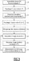
- the picture 3 represents the main steps implemented in a method for assisting the guidance of an endovascular tool in vascular structures according to one embodiment of the invention, implemented by a processor 36.
- the method comprises, in a first operating phase, a first step 50 of acquiring N two-dimensional fluoroscopic images of a lower limb of the patient, for example 3 or 4 successive images acquired by translation of the imaging device along the femoral axis.
- the two-dimensional fluoroscopic images are denoted ⁇ F 1 ,..,F i ,...F N ⁇ and are stored in the form of digital images. Two successive images are partially superimposed, and therefore have a rectangular superimposition zone of variable size when the device is moved by the operator, preferably greater than or equal to a predetermined size.
- each digital image is represented as a two-dimensional matrix of pixels, each pixel having an associated numerical value called intensity
- the size of the image is defined by a number of rows and a number of columns
- an area overlay has a number of rows and columns forming a given surface area, preferably greater than or equal to 20% of the total image surface.
- Step 50 is followed by a step 52 of registering the two-dimensional fluoroscopic images two by two to form a first augmented image, denoted P 1 , representative of a complete bone panorama of the lower limb represented.
- the registration of images or spatial correspondence consists in placing in spatial correspondence anatomical or functional structures present in each of the images.
- an augmented image is obtained representing the bone structure of the entire lower limb.
- the aim of the registration is to produce a precise superposition of the bone structures present in the superposition zone common to the successive images.
- 2D/2D registration consists of optimizing two translations and one rotation.
- the two-dimensional fluoroscopic images acquired present a relatively high level of contrast thanks to the bones.
- automatic registration of the iconic type can be implemented, using a measure of similarity based on the difference in gradients between the two images, coupled with an optimization strategy of the gradient descent or Powell optimizer type.
- a first augmented image P 1 is obtained representing a bone panorama of the lower limb of the patient.
- the image P 1 is obtained from a plurality of two-dimensional fluoroscopic images acquired.
- At least a second augmented image of the lower limb of the patient is obtained.
- This second augmented image includes a representation of the vascular structures of the patient's lower limb.
- step 54 Two different embodiments of step 54 are contemplated and will be described in more detail below with reference to the figure 4 and 5 .
- the second augmented image is a two-dimensional image representative of an arterial panorama of the lower limb considered, located in the same spatial reference as the bone panorama P 1 .
- the arterial panorama is obtained from two-dimensional angiographic images representing the vascular structures of the lower limb considered. Since the angiographic images obtained are in the same spatial reference as the fluoroscopic images, the registration parameters obtained in step 50 are directly applied to the angiographic images to obtain the arterial panorama.
- the second augmented image is a three-dimensional image of the bone and vascular structures of the lower limb considered.
- the second augmented image is obtained in a preliminary, pre-operative phase, and stored. It is for example calculated from images obtained by acquisition techniques such as for example tomography also called CT for "computed tomography", magnetic resonance imaging (MRI), enhanced by the injection of contrast product to better show the vascular structures.
- acquisition techniques such as for example tomography also called CT for "computed tomography", magnetic resonance imaging (MRI), enhanced by the injection of contrast product to better show the vascular structures.
- both a second augmented image representative of an arterial panorama and a third three-dimensional image of the bone and vascular structures of the lower limb considered are used.
- step 54 is followed by an optional step 56 of registration between the first and second augmented images.
- step 56 it is useful to represent a merged image P 3 of the bone panorama P 1 and of the augmented image P 2 , which will be used for the simultaneous visualization of the bone and arterial structures.
- Step 56 or step 54 is optionally followed by a step 58 of marking, by the operator of the system, for example a doctor, of the arterial lesions observed on the second augmented image P 2 .
- a current fluoroscopic image I c is acquired at step 60.
- the second operating phase is an effective intervention phase, during which an endovascular tool, selected from a catheter, an endovascular device of the stent type , a flexible or rigid guide, a stent or a balloon, is introduced to treat the patient.
- the current fluoroscopic image I c is then readjusted with respect to the first augmented image P 1 representative of a bone panorama of the lower limb in step 62.
- the registration consists here in placing in spatial correspondence the anatomical bone structures present in the current fluoroscopic image I c with structures of the first augmented image P 1 .
- the registration used here is thus of the "template matching" type because of the membership of the current image I c has a very specific part of the first augmented image P 1 .
- the registration performed is of the iconic type, using a measure of similarity based on the difference in gradients between the two images, a measure of similarity based on the mutual information, or a combination of the two.
- step 64 an image zone corresponding to the current fluoroscopic image I c is determined in the second augmented image P 2 and/or in the merged image P 3 , and displayed, using information from readjustment calculated and stored between the first augmented image P 1 and the second augmented image P 2 .
- the local vascular structure is displayed in connection with the current fluoroscopic image without requiring a new acquisition of the angiographic image, and consequently without the need to inject a supplement of contrast product.
- the lesions are located precisely with respect to the current fluoroscopic image thanks to the readjustments carried out between the current fluoroscopic image and the first augmented image P 1 and thanks to the registration between the first augmented image P 1 and the second augmented image P 2 .
- Steps 60 to 64 are iterated substantially in real time as much as necessary during the intervention, in particular for each lesion to be treated on the lower limb.
- the figure 4 illustrates in more detail a first embodiment of the invention, in which the second augmented image P 2 is an arterial panorama of the patient's lower limb.
- an image is acquired fluoroscopic F i and an angiographic image A i .
- an image is acquired fluoroscopic F i and an angiographic image A i .
- Step 72 of resetting is analogous to step 52 previously described.
- the 2D-2D rigid registration parameters between successive fluoroscopic images are stored, and then applied in step 74 to the angiographic images A i to obtain the second augmented image P 2 .
- the registration parameters are calculated on the fluoroscopic images which have good contrast thanks to the presence of the bone structures. Thanks to the acquisition of fluoroscopic and angiographic images in spatial correspondence, a panorama of the vascular structures corresponding to the bone panorama is easily obtained.
- the first and second augmented images are merged at the merging step 76 into a merged image P 3 showing both the bony and vascular structures of the entire lower limb studied.
- the fusion comprises for example a sum weighted by weighting coefficients, pixel by pixel, of the augmented images P 1 and P 2 , the weighting coefficients associated with the respective pixels being chosen as a function of the initial intensity of the images.
- the image P 3 is displayed, for example next to the second augmented image P 2 .
- display variants are possible.
- the operator adds markers, the position of which is recorded, to mark the arterial lesions to be treated.
- the markers are preferably added to the second augmented image P 2 representative of the panorama of the vascular structures, and transferred precisely to the merged image P 3 .
- the markers are for example represented by colored lines superimposed on the image or images displayed.
- the markers are added to the second augmented image P 2 before step 76 of calculating the merged image P 3 , and are transferred to the displayed merged image.
- the markers are added directly to the merged image P 3 .
- Step 80 of current fluoroscopic image acquisition I c is analogous to step 60 described above.
- the current fluoroscopic image is then readjusted with respect to the first augmented image P 1 at step 82, analogous to step 62 previously described.
- step 84 the vascular structures corresponding to the current fluoroscopic image are relocated in the second augmented image P 2 and/or in the merged image P 3 , and are displayed.
- a frame indicating the zone corresponding to the current fluoroscopic image is displayed, both on the augmented image P 2 and the merged image P 3 , which are displayed in parallel, as well as previously positioned markers, as shown in the example in figure 6 .
- the left part represents a merged image, comprising the bone panorama of the first augmented image merged with the current fluoroscopic image, as well as markers delimiting an arterial lesion.
- the second augmented image representative of the arterial panorama is shown, also with boundary markers of the same arterial lesion.
- an image representative of the current fluoroscopic image with the corresponding angiographic structure superimposed, and, if applicable, with the previously recorded markers, is displayed, with a better display resolution than the resolution of the zone displayed on the augmented image P 2 or on the image P 3 .
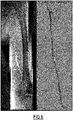
- the figure 7 illustrates an example of display of a current fluoroscopic image, with the corresponding angiographic structure from the second augmented image superimposed.
- the arterial lesions to be treated are relocated, in connection with the current fluoroscopic image and with the augmented P 2 and merged P 3 images of the lower limb, which makes it possible to help guide the endovascular tool introduced in during surgery without new angiographic image acquisition.
- the figure 5 illustrates in more detail a second embodiment of the invention, in which the second augmented image P 2 is a 3D image representative of the bone and vascular structures of the patient's lower limb.
- the second augmented image P 2 is obtained and stored in a preoperative phase.
- This three-dimensional image is for example calculated from images obtained in the pre-operative step 90 by acquisition techniques such as for example tomography also called CT for "computed tomography", or magnetic resonance imaging (MRI ), enhanced by the injection of contrast product to better highlight the vascular structures.
- acquisition techniques such as for example tomography also called CT for "computed tomography", or magnetic resonance imaging (MRI ), enhanced by the injection of contrast product to better highlight the vascular structures.
- a 3D image is calculated and stored in the pre-operative step 92.
- working on the CT image obtained with injection of contrast product automatic segmentation of arterial structures can be used to create a three-dimensional anatomical model of the patient.
- a graph cut type semi-automatic segmentation algorithm can be used.
- such a virtual three-dimensional anatomical model may include segmented volumes of the femoral artery, internal iliac arteries, hips, and femur.
- the method comprises a step 94 of acquiring two-dimensional fluoroscopic images, analogous to step 50 previously described, followed by a registration step 96 to form the first augmented image P 1 , analogous to step 52 previously described.
- a rigid 2D-3D registration is then applied in step 98, and parameters allowing the matching of the first augmented image P 1 and the second three-dimensional augmented image are stored.
- Any known rigid 2D-3D registration method is applicable.
- a semi-automatic registration of the iconic type is implemented, in which the initialization of part of the points used for the registration is carried out manually, which makes it possible to roughly match the two images to be registered, and the automatic registration is then launched afterwards to refine the result.
- Step 98 is followed by steps 100 of acquisition of a current two-dimensional fluoroscopic image, representative of a portion of the lower limb considered, analogous to step 60 previously described, then by a step 102 of registration with respect to the first augmented image P 1 , analogous to step 62 already described.
- step 104 an area corresponding to the current image is determined in the three-dimensional image P 2 , by applying the 2D-3D matching parameters between the first augmented image P 1 and the three-dimensional image P 2 calculated and stored in step 98.
- a 2D-3D registration is performed at step 104.
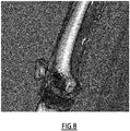
- the figure 8 illustrates an example of a 3D image representative of the bony and vascular structures of a portion of the lower limb, superimposed with a current fluoroscopic image.
- the first two embodiments are combined.
- the second augmented image P 2 representative of an arterial panorama is calculated and displayed, as in the first embodiment.
- another augmented image P′ 2 which is the three-dimensional image representative of the bony and vascular structures of the lower limb, is also calculated and displayed as in the second embodiment.
- the zone corresponding to the current fluoroscopic image is determined and displayed on each of the augmented images.
- the method allows the display, in the second operating phase, of a zone corresponding to the current fluoroscopic image both in the augmented image corresponding to the arterial panorama, and in the three-dimensional augmented image.
- the operator has information on the arterial lesions, as well as additional information on the patient, for example the location of the calcifications visible only in the 3D image.
Landscapes
- Health & Medical Sciences (AREA)
- Life Sciences & Earth Sciences (AREA)
- Engineering & Computer Science (AREA)
- Medical Informatics (AREA)
- Surgery (AREA)
- Public Health (AREA)
- Veterinary Medicine (AREA)
- Heart & Thoracic Surgery (AREA)
- Biomedical Technology (AREA)
- Molecular Biology (AREA)
- Animal Behavior & Ethology (AREA)
- General Health & Medical Sciences (AREA)
- Nuclear Medicine, Radiotherapy & Molecular Imaging (AREA)
- Biophysics (AREA)
- Radiology & Medical Imaging (AREA)
- Physics & Mathematics (AREA)
- Pathology (AREA)
- High Energy & Nuclear Physics (AREA)
- Optics & Photonics (AREA)
- Robotics (AREA)
- Computer Vision & Pattern Recognition (AREA)
- Dentistry (AREA)
- Oral & Maxillofacial Surgery (AREA)
- Vascular Medicine (AREA)
- Apparatus For Radiation Diagnosis (AREA)
- Orthopedic Medicine & Surgery (AREA)
- Human Computer Interaction (AREA)
Description
- La présente invention concerne un système d'aide au guidage d'un outil endovasculaire dans des structures vasculaires d'une zone anatomique d'intérêt d'un patient, par exemple un membre inférieur d'un patient. Elle concerne également un procédé et un dispositif d'aide au guidage d'un outil endovasculaire dans des structures vasculaires associé.
- Elle trouve une application dans le domaine des interventions endovasculaires guidées par l'image.
- Les interventions endovasculaires permettent de traiter des maladies vasculaires de façon minimalement invasive. Elles consistent généralement à insérer par voie endovasculaire un dispositif médical dans le but d'interagir avec les tissus pathologiques. Des interventions endovasculaires sont notamment utilisées pour traiter les sténoses et les thromboses artérielles, via l'introduction de divers d'outils endovasculaires adaptés tels qu'un ballon ou un stent.
- Contrairement aux interventions chirurgicales classiques qui nécessitent de réaliser une large ouverture du corps du patient pour accéder aux tissus d'intérêt, les interventions endovasculaires ne demandent que de fines incisions pour pouvoir insérer les outils dans la structure vasculaire. Elles présentent plusieurs avantages, notamment une augmentation du taux de succès à court terme ainsi qu'une diminution de la morbidité peropératoire et de la durée d'hospitalisation. Malgré la généralisation de ces interventions, elles restent délicates et nécessitent d'être sécurisées et fiabilisées. L'accès aux tissus pathologiques est rendu difficile par la nature de l'intervention. La manipulation et le contrôle des outils endovasculaires exigent une précision importante pour favoriser la réussite du traitement. Par ailleurs, le suivi des gestes opératoires ne peut être réalisé que par l'intermédiaire d'une imagerie peropératoire.
- Dans le domaine des interventions endovasculaires on utilise des images bidimensionnelles acquises par fluoroscopie, permettant de guider l'insertion de dispositifs médicaux, tels des cathéters, dans l'artère fémorale et dans d'autres ramifications vasculaires.
- La fluoroscopie désigne une technique d'imagerie médicale utilisant des rayons X qui permet de visualiser des structures anatomiques en mouvement et en temps réel, en particulier des structures osseuses.
- Les artères étant des tissus mous et donc non visibles aux rayons X, on administre au patient un produit de contraste radio-opaque afin d'opacifier la structure vasculaire et de visualiser le cheminement des artères. On peut alors obtenir des images exploitables. Cette technique d'acquisition d'images des structures vasculaires, en particulier des artères, d'un patient est connue sous le nom d'angiographie, et les images obtenues sont appelées images angiographiques.
- Les images fluoroscopiques et angiographiques bidimensionnelles sont acquises et utilisées pendant une phase opératoire, donc une phase d'intervention.
- En général, les salles d'opération conventionnelles sont équipées d'un dispositif de support d'un dispositif d'imagerie à rayons X, connu sous le nom d'arceau ou de dispositif C-arm, mobile, et permettant d'acquérir des images fluoroscopiques et angiographiques avec un champ de vision donné.
- Dans le cas particulier des procédures endovasculaires pour traiter l'artériopathie oblitérante des membres inférieurs, il existe un intérêt d'obtenir des images de la totalité d'un membre inférieur du patient. Or le champ de vision d'un dispositif d'acquisition d'images étant limité, il est nécessaire d'acquérir une pluralité d'images fluoroscopiques et angiographiques, de préférence partiellement superposées, pour obtenir par traitement d'images une image composite ou panoramique d'une zone anatomique d'intérêt, par exemple d'un membre inférieur du patient dans sa totalité.
- De plus, dans le cadre des interventions endovasculaires conventionnelles, pour traitement des membres inférieurs, si les occlusions artérielles sont de grande taille ou occultées, elles ne peuvent pas être visualisées sur une seule image angiographique, donc plusieurs captures d'images angiographiques sont nécessaires, dans un premier temps pour visualiser l'ensemble des lésions à traiter, puis, dans un deuxième temps, pour effectuer précisément le traitement de chaque lésion.
- Cependant, chaque acquisition d'image angiographique nécessite l'injection d'un produit de contraste, qui est toxique pour le patient. Par exemple, un produit de contraste iodé est néphrotoxique.
- De plus, chaque acquisition d'image supplémentaire expose le patient et le personnel médical présent en salle d'opération à une quantité de rayonnement X supplémentaire.
-
WO 2006/063141 A2 divulgue un système d'aide au guidage selon le préambule de la revendication 1. - L'invention a pour objet de remédier aux inconvénients des méthodes connues; pour améliorer les interventions endovasculaires guidées par l'image tout en limitant le nombre d'acquisitions d'images angiographiques.
- A cet effet, l'invention propose un système d'aide au guidage d'un outil endovasculaire dans des structures vasculaires d'une zone anatomique d'intérêt d'un patient, comprenant un dispositif d'imagerie apte à acquérir des images bi-dimensionnelle de portions du corps d'un patient, un dispositif programmable et une unité de visualisation, selon la revendication 1.
- Avantageusement, le système de l'invention comprend l'affichage d'une zone d'image correspondant à une image fluoroscopique courante dans une image augmentée comprenant une représentation des structures vasculaires de la portion de la zone anatomique d'intérêt visualisable dans l'image fluoroscopique courante, sans nécessité de ré-injecter du produit de contraste radio-opaque dans le corps du patient.
- Le système selon l'invention peut également présenter une ou plusieurs des caractéristiques
- Selon un autre aspect, l'invention concerne un programme d'ordinateur selon la revendication 7.
- D'autres caractéristiques et avantages de l'invention ressortiront de la description qui en est donnée ci-dessous, à titre indicatif et nullement limitatif, en référence aux figures annexées, parmi lesquelles :
- la
figure 1 représente schématiquement un système d'intervention endovasculaire guidée par l'image; - la
figure 2 est un synoptique des principaux blocs d'un dispositif programmable apte à mettre en œuvre le procédé de l'invention ; - la
figure 3 est un organigramme des principales étapes d'un procédé d'aide au guidage d'un outil endovasculaire selon l'invention ; - la
figure 4 est un organigramme des principales étapes d'un procédé selon un premier mode de réalisation ; - la
figure 5 est un organigramme des principales étapes d'un procédé selon un deuxième mode de réalisation ; - la
figure 6 est un exemple d'affichage des première et deuxième images augmentées selon un mode de réalisation ; - la
figure 7 est un exemple d'affichage en superposition d'informations fluoroscopiques et angiographiques ; - la
figure 8 est un exemple de représentation 3D des structures osseuse et vasculaire. - L'invention est décrite ci-après plus particulièrement pour une aide au guidage d'outil endovasculaire dans les membres inférieurs, mais l'invention s'applique plus généralement à d'autres zones anatomiques d'intérêt, ou à une zone plus large incluant également tout ou partie du tronc du patient.
- La
figure 1 illustre schématiquement une salle d'opération 1, équipée d'un système 10 d'intervention endovasculaire guidée par l'image. - La salle d'opération 1 est équipée d'une table d'opération 12, sur laquelle est représenté un patient 14 à traiter par une intervention endovasculaire.
- Le système d'intervention 10 comporte un dispositif 21 d'imagerie à rayon X, lui-même composé d'un dispositif de support 16 en forme d'arceau, d'une source 18 de rayons X et d'une unité 20 de réception et de détection de rayons X, positionnée en regard de la source 18. Ce dispositif d'imagerie est apte à capter des images des éléments positionnés entre la source 18 de rayons X et l'unité 20 de réception et de détection, et est également apte à tourner autour de deux axes selon le besoin de l'opérateur.
- On appelle généralement les images bidimensionnelles captées par un système d'imagerie à rayons X des images fluoroscopiques.
- Ainsi, le dispositif d'imagerie 21 illustré est adapté pour capter des images bidimensionnelles fluoroscopiques de diverses zones anatomiques d'intérêt du corps du patient, comprenant des structures vasculaires ciblées, en particulier des artères.
- En particulier, l'opérateur peut déplacer le dispositif d'imagerie 21 sensiblement en translation le long des jambes du patient 14, pour acquérir une pluralité de N d'images fluoroscopiques Fi.
- Plus généralement, l'opérateur peut déplacer le dispositif d'imagerie 21 sensiblement en translation pour obtenir une pluralité d'images fluoroscopiques d'une zone anatomique d'intérêt choisie ou s'étendant du tronc supra-aortique aux pieds du patient.
- Alternativement, le déplacement en translation du dispositif d'imagerie 21 est commandé, par exemple par le dispositif programmable 22, décrit ci-après.
- Le nombre N d'images à acquérir est choisi en fonction du champ de vision du dispositif d'imagerie et de la taille du patient 14. Par exemple, 3 à 4 images de chaque jambe du patient 14 sont acquises le long de l'axe fémoral.
- Le dispositif d'imagerie est positionné à des positions successives telles que deux images acquises successivement présentent une superposition partielle sur une zone de superposition rectangulaire, de taille prédéterminée ou variable.
- De préférence, la zone de superposition a une surface supérieure ou égale à 20% de la surface des images bidimensionnelles acquises.
- Le dispositif d'imagerie 21 est adapté à acquérir également des images angiographiques Ai de la jambe ou des jambes du patient, suite à une injection de produit de contraste radio-opaque par une unité d'injection 19.
- Comme il sera expliqué plus en détail par la suite, dans un mode de réalisation de l'invention, lors d'une première phase opératoire de préparation, à chaque position successive du dispositif d'imagerie, une image fluoroscopique et une image angiographique correspondantes sont acquises et mémorisées sous forme d'images numériques bidimensionnelles.
- Le système d'intervention 10 comporte également un dispositif programmable 22, comportant un ou plusieurs processeurs, associé à une unité de visualisation 24 composée d'un ou de plusieurs écrans et d'une interface homme-machine 26.
- L'interface homme-machine 26 comprend des moyens de pointage et de sélection d'éléments, par exemple un ensemble clavier-souris, un pavé tactile, une interface gestuelle 3D sans contact ou une combinaison de ces dispositifs.
- Dans un mode de réalisation, l'interface homme-machine 26 est intégrée avec l'unité de visualisation 24 sous la forme d'un écran tactile.
- Le dispositif programmable 22 est adapté à recevoir les images bidimensionnelles (fluoroscopiques et/ou angiographiques) acquises par le dispositif d'imagerie à rayons X et à les traiter selon un procédé d'aide au guidage d'un outil endovasculaire dans des structures vasculaires selon l'invention.
- Dans un mode de réalisation, le dispositif programmable 22 est adapté à commander l'acquisition d'images bidimensionnelles (fluoroscopiques et/ou angiographiques).
- Les images bidimensionnelles acquises pendant la phase d'intervention sont affichées sur l'unité de visualisation 24 pour aider à un guidage précis des outils endovasculaires à l'intérieur des structures vasculaires, en particulier des artères, du patient.
- Les outils endovasculaires sont sélectionnés parmi un cathéter, un dispositif endovasculaire de type stent, un guide souple ou rigide, une endoprothèse ou un ballon.
- La
figure 2 illustre les principaux blocs d'un dispositif programmable 30 apte à mettre en œuvre le procédé d'aide au guidage d'un outil endovasculaire dans des structures vasculaires selon un mode de réalisation de l'invention. - Un dispositif programmable 30 apte à mettre en oeuvre l'invention, comprend un écran 32, analogue à l'unité de visualisation 24, une unité 34 de saisie des commandes d'un opérateur, par exemple un clavier, une souris, un pavé tactile ou une interface sans contact, analogue à l'unité 26, une unité centrale de traitement 36, ou CPU, apte à exécuter des instructions de programme informatique lorsque le dispositif 30 est mis sous tension. Le dispositif 30 comporte optionnellement un contrôleur 40, permettant d'envoyer des commandes et de sélectionner des éléments à distance.
- Le dispositif 30 comporte également une unité de stockage d'informations 38, par exemple des registres, aptes à stocker des instructions de code exécutable permettant la mise en oeuvre de programmes comportant des instructions de code aptes à mettre en oeuvre le procédé selon l'invention. Les divers blocs fonctionnels du dispositif 30 décrits ci-dessus sont connectés via un bus de communication 42.
- Le dispositif 30 est apte à recevoir des données d'image d'une source 44.
- Dans un mode de réalisation, le dispositif 30 est adapté à coopérer avec un dispositif d'imagerie pour acquérir des images fluoroscopiques et/ou angiographiques. En particulier, le dispositif 30 est adapté à commander le dispositif d'imagerie pour acquérir une pluralité d'images angiographiques correspondant à la pluralité d'images fluoroscopiques.
- Le procédé de l'invention est adapté à être mis en oeuvre par un dispositif programmable 30 tel un ordinateur intégré dans une salle d'intervention standard, ce qui permet de limiter les coûts d'équipement.
- Dans un mode de réalisation, le procédé de l'invention est mis en oeuvre par des modules de code logiciel. Les instructions de code exécutable sont enregistrées sur un support lisible par ordinateur, par exemple un disque optique, un disque magnéto-optique, une mémoire ROM, une mémoire RAM, une mémoire non volatile (EPROM, EEPROM, FLASH, NVRAM), une carte magnétique ou optique. En variante les modules de code logiciel sont réalisés sous forme d'un composant logique programmable tel qu'un FPGA (pour Field Programmable Gate Array), ou encore sous forme de circuit intégré dédié tel qu'un ASIC (pour Application Specific Integrated Circuit).
- Le dispositif programmable 30 est adapté à :
- obtenir une pluralité d'images fluoroscopiques partiellement superposées de la zone anatomique d'intérêt, et former une première image augmentée représentative d'un panorama osseux complet de ladite zone anatomique d'intérêt,
- obtenir une deuxième image augmentée comportant une représentation des structures vasculaires de ladite zone anatomique d'intérêt,
- obtenir une nouvelle image fluoroscopique, dite image fluoroscopique courante, d'une portion de la zone anatomique d'intérêt,
- recaler ladite image fluoroscopique courante par rapport à la première image augmentée, localiser et afficher sur l'unité de visualisation une zone d'image correspondant à l'image fluoroscopique courante dans la deuxième image augmentée.
- La
figure 3 représente les principales étapes mises en œuvre dans un procédé d'aide au guidage d'un outil endovasculaire dans des structures vasculaires selon un mode de réalisation de l'invention, mises en oeuvre par un processeur 36. - Le procédé comporte, dans une première phase opératoire, une première étape 50 d'acquisition de N images fluoroscopiques bidimensionnelles d'un membre inférieur du patient, par exemple 3 ou 4 images successives acquises par translation du dispositif d'imagerie le long de l'axe fémoral.
- Les images fluoroscopiques bidimensionnelles sont notées {F1,..,Fi,...FN} et sont mémorisées sous forme d'images numériques. Deux images successives sont partiellement superposées, et présentent donc une zone de superposition rectangulaire de taille variable lorsque le dispositif est déplacé par l'opérateur, de préférence supérieure ou égale à une taille prédéterminée.
- Par exemple, lorsque chaque image numérique est représentée sous forme d'une matrice bidimensionnelle de pixels, chaque pixel ayant une valeur numérique associée appelée intensité, la taille de l'image est définie par un nombre de lignes et un nombre de colonnes, une zone de superposition comporte un nombre de lignes et de colonnes formant une zone de surface donnée, de préférence supérieure ou égale à 20% de la surface totale de l'image.
- L'étape 50 est suivie d'une étape 52 de recalage deux à deux des images fluoroscopiques bidimensionnelles pour former une première image augmentée, notée P1, représentative d'un panorama osseux complet du membre inférieur représenté.
- Le recalage d'images ou mise en correspondance spatiale consiste à placer en correspondance spatiale des structures anatomiques ou fonctionnelles présentes dans chacune des images. Par fusion successive des images recalées le long du membre inferieur, on obtient une image augmentée représentant la structure osseuse de la totalité du membre inférieur.
- Dans le cas d'application présent, le recalage a pour objectif de réaliser une superposition précise des structures osseuses présentes dans la zone de superposition commune aux images successives.
- Deux images successives peuvent présenter une légère rotation entre elles, en particulier lorsque l'opérateur déplace le dispositif d'imagerie. Le recalage 2D/2D consiste à optimiser deux translations et une rotation.
- Les images fluoroscopiques bidimensionnelles acquises présentent un niveau de contraste relativement important grâce aux os. Il existe plusieurs méthodes de recalage rigide entre images bidimensionnelles (ou recalage 2D-2D) applicables pour des images comprenant des objets ayant un niveau de contraste relativement élevé.
- Par exemple, un recalage automatique de type iconique peut être mis en oeuvre, en utilisant une mesure de similarité basée sur la différence de gradients entre les deux images, couplé à une stratégie d'optimisation de type descente de gradient ou optimiseur de Powell.
- Suite à l'étape 52 de recalage 2D-2D est obtenue une première image augmentée P1 représentant un panorama osseux du membre inférieur du patient. Comme expliqué ci-dessus l'image P1 est obtenue à partir d'une pluralité d'images bidimensionnelles fluoroscopique acquises.
- Lors d'une étape 54, au moins une deuxième image augmentée du membre inférieur du patient est obtenue. Cette deuxième image augmentée comporte une représentation des structures vasculaires du membre inférieur du patient.
- Deux modes de réalisation différents de l'étape 54 sont envisagés et seront décrits plus en détail ci-après en référence aux
figures 4 et5 . - Dans un premier mode de réalisation, la deuxième image augmentée est une image bidimensionnelle représentative d'un panorama artériel du membre inférieur considéré, situé dans le même repère spatial que le panorama osseux P1.
- Le panorama artériel est obtenu à partir d'images angiographiques bidimensionnelles représentant les structures vasculaires du membre inférieur considéré. Les images angiographiques obtenues étant dans le dans le même repère spatial que les images fluoroscopiques, les paramètres de recalage obtenus à l'étape 50 sont directement appliqués aux images angiographiques pour obtenir le panorama artériel.
- Dans un deuxième mode de réalisation, la deuxième image augmentée est une image tridimensionnelle des structures osseuse et vasculaire du membre inférieur considéré. Dans ce deuxième mode de réalisation, la deuxième image augmentée est obtenue dans une phase préalable, pré-opératoire, et mémorisée. Elle est par exemple calculée à partir d'images obtenues par des techniques d'acquisition comme par exemple la tomographie également appelée CT pour « computed tomography », l'imagerie par résonance magnétique (IRM), rehaussés par l'injection de produit de contraste pour mieux faire apparaitre les structures vasculaires.
- Dans un troisième mode de réalisation, on utilise à la fois une deuxième image augmentée représentative d'un panorama artériel et une troisième image tridimensionnelle des structures osseuse et vasculaire du membre inférieur considéré.
- Dans le cas d'obtention d'une image augmentée de type image tridimensionnelle pré-opératoire, l'étape 54 est suivie d'une étape optionnelle 56 de recalage entre les première et deuxième images augmentées.
- Suite à l'étape 56, il est utile de représenter une image fusionnée P3 du panorama osseux P1 et de l'image augmentée P2, qui servira pour la visualisation simultanée des structures osseuses et artérielles.
- L'étape 56 ou l'étape 54 est suivie optionnellement d'une étape 58 de marquage, par l'opérateur du système, par exemple un médecin, des lésions artérielles observées sur la deuxième image augmentée P2.
- Dans une deuxième phase opératoire, une image fluoroscopique courante Ic est acquise à l'étape 60. La deuxième phase opératoire est une phase d'intervention effective, lors de laquelle un outil endovasculaire, sélectionné parmi un cathéter, un dispositif endovasculaire de type stent, un guide souple ou rigide, une endoprothèse ou un ballon, est introduit pour traiter le patient.
- L'image fluoroscopique courante Ic est ensuite recalée par rapport à la première image augmentée P1 représentative d'un panorama osseux du membre inférieur à l'étape 62.
- Le recalage consiste ici à placer en correspondance spatiale des structures anatomiques osseuses présentes dans l'image fluoroscopique courante Ic avec des structures de la première image augmentée P1.Le recalage utilisé ici est ainsi de type « template matching » du fait de l'appartenance de l'image courante Ic a une partie bien précise de la première image augmentée P1.
- De préférence, le recalage effectué est de type iconique, en utilisant une mesure de similarité basée sur la différence de gradients entre les deux images, une mesure de similarité basée sur l'information mutuelle, ou une combinaison des deux.
- Enfin, à l'étape 64, une zone d'image correspondant à l'image fluoroscopique courante Ic est déterminée dans la deuxième image augmentée P2 et/ou dans l'image fusionnée P3, et affichée, grâce à des informations de recalage calculées et mémorisées entre la première image augmentée P1 et la deuxième image augmentée P2.
- Avantageusement, la structure vasculaire locale est affichée en lien avec l'image fluoroscopique courante sans nécessiter une nouvelle acquisition d'image angiographique, et par conséquent sans nécessité d'injecter un supplément de produit de contraste.
- Avantageusement, dans le cas où le marquage des lésions a été effectué lors de l'étape 58, les lésions sont localisées précisément par rapport à l'image fluoroscopique courante grâce aux recalages effectués entre l'image fluoroscopique courante et la première image augmentée P1 et grâce au recalage entre la première image augmentée P1 et la deuxième image augmentée P2.
- Les étapes 60 à 64 sont itérées sensiblement en temps réel autant que nécessaire durant l'intervention, notamment pour chaque lésion à traiter sur le membre inférieur.
- La
figure 4 illustre plus en détail un premier mode de réalisation de l'invention, dans lequel la deuxième image augmentée P2 est un panorama artériel du membre inférieur du patient. - Dans ce premier mode de réalisation, à l'étape d'acquisition d'images 70, à chaque position d'acquisition d'images du dispositif d'imagerie, on acquiert une image fluoroscopique Fi et une image angiographique Ai. Ainsi, il y a une correspondance spatiale initiale entre ces images. En d'autres termes, les images sont acquises dans le même repère spatial.
- L'étape 72 de recalage est analogue à l'étape 52 précédemment décrite. Les paramètres de recalage rigide 2D-2D entre images fluoroscopiques successives sont mémorisés, et appliqués ensuite à l'étape 74 aux images angiographiques Ai pour obtenir la deuxième image augmentée P2.
- Ainsi, avantageusement, les paramètres de recalage sont calculés sur les images fluoroscopiques qui présentent un bon contraste grâce à la présence des structures osseuses. Grâce à l'acquisition des images fluoroscopiques et angiographiques en correspondance spatiale, un panorama des structures vasculaires correspondant au panorama osseux est obtenu aisément.
- Les première et deuxième images augmentées sont fusionnées à l'étape de fusion 76 dans une image fusionnée P3 faisant apparaître à la fois les structures osseuses et vasculaires de la totalité du membre inférieur étudié. La fusion comprend par exemple une somme pondérée par des coefficients de pondération, pixel par pixel, des images augmentées P1 et P2, les coefficients de pondération associés aux pixels respectifs étant choisis en fonction de l'intensité initiale des images.
- L'image P3 est affichée, par exemple à côté de la deuxième image augmentée P2. Bien évidemment, des variantes d'affichage sont envisageables.
- A l'étape optionnelle de marquage 78, l'opérateur ajoute des marqueurs, dont la position est enregistrée, pour marquer les lésions artérielles à traiter.
- Les marqueurs sont de préférence ajoutés sur la deuxième image augmentée P2 représentative du panorama des structures vasculaires, et reportés précisément sur l'image fusionnée P3. Les marqueurs sont par exemple représentés par des traits de couleur superposés sur la ou les images affichées.
- En variante, les marqueurs sont ajoutés sur la deuxième image augmentée P2 avant l'étape 76 de calcul de l'image fusionnée P3, et sont reportés sur l'image fusionnée affichée.
- Selon une autre variante, les marqueurs sont ajoutés directement sur l'image fusionnée P3.
- L'étape 80 d'acquisition d'image fluoroscopique courante Ic est analogue à l'étape 60 décrite précédemment.
- L'image fluoroscopique courante est ensuite recalée par rapport à la première image augmentée P1 à l'étape 82, analogue à l'étape 62 précédemment décrite.
- Ensuite, à l'étape 84, les structures vasculaires correspondant à l'image fluoroscopique courante sont relocalisées dans la deuxième image augmentée P2 et/ou dans l'image fusionnée P3, et sont affichées.
- Par exemple, dans un mode de réalisation, un cadre indiquant la zone correspondant à l'image fluoroscopique courante est affiché, à la fois sur l'image augmentée P2 et l'image fusionnée P3, qui sont affichées en parallèle, ainsi que les marqueurs précédemment positionnés, comme illustré dans l'exemple de la
figure 6 . - Dans la
figure 6 , la partie de gauche représente une image fusionnée, comportant le panorama osseux de la première image augmentée fusionné avec l'image fluoroscopique courante, ainsi que des marqueurs de délimitation d'une lésion artérielle. En parallèle, sur la partie droite de la figure, la deuxième image augmentée représentative du panorama artériel est représentée, avec également des marqueurs de délimitation de la même lésion artérielle. - De plus, selon une variante, une image représentative de l'image fluoroscopique courante avec en superposition la structure angiographique correspondante, et, le cas échéant, avec les marqueurs préalablement enregistrés, est affichée, avec une meilleure résolution d'affichage que la résolution de la zone affichée sur l'image augmentée P2 ou sur l'image P3.
- La
figure 7 illustre un exemple d'affichage d'une image fluoroscopique courante, avec en superposition la structure angiographique correspondante issue de la deuxième image augmentée. - Ainsi, avantageusement, les lésions artérielles à traiter sont relocalisées, en lien avec l'image fluoroscopique courante et avec les images augmentée P2 et fusionnée P3 du membre inférieur, ce qui permet d'aider au guidage de l'outil endovasculaire introduit en cours d'intervention sans nouvelle acquisition d'image angiographique.
- La
figure 5 illustre plus en détail un deuxième mode de réalisation de l'invention, dans lequel la deuxième image augmentée P2 est une image 3D représentative des structures osseuses et vasculaires du membre inférieur du patient. - Dans ce mode de réalisation, la deuxième image augmentée P2 est obtenue et mémorisée dans une phase préopératoire. Cette image tridimensionnelle est par exemple calculée à partir d'images obtenues à l'étape pré-opératoire 90 par des techniques d'acquisition comme par exemple la tomographie également appelée CT pour « computed tomography », ou l'imagerie par résonance magnétique (IRM), rehaussés par l'injection de produit de contraste pour mieux faire ressortir les structures vasculaires.
- A partir des images obtenues une image 3D est calculée et mémorisée à l'étape pré-opératoire 92. Il existe diverses méthodes connues de calcul d'une telle image. Par exemple, en travaillant sur l'image CT obtenue avec injection de produit de contraste, une segmentation automatique des structures artérielles peut être utilisée pour créer un modèle anatomique tridimensionnel du patient. Un algorithme de segmentation semi-automatique de type coupe de graphe peut être utilisé.
- Par exemple, un tel modèle anatomique tridimensionnel virtuel peut comprendre les volumes segmentés de l'artère fémorale, des artères iliaques internes, des hanches et du fémur.
- En phase opératoire, le procédé comporte une étape 94 d'acquisition d'images bidimensionnelles fluoroscopiques, analogue à l'étape 50 précédemment décrite, suivie d'une étape de recalage 96 pour former la première image augmentée P1, analogue à l'étape 52 précédemment décrite.
- Un recalage 2D-3D rigide est ensuite appliqué à l'étape 98, et des paramètres permettant la mise en correspondance de la première image augmentée P1 et la deuxième image augmentée tridimensionnelle sont mémorisés.
- Toute méthode de recalage 2D-3D rigide connue est applicable. Par exemple, un recalage semi-automatique de type iconique est mis en oeuvre, dans lequel l'initialisation d'une partie des points utilisés pour le recalage est effectuée manuellement, ce qui permet de faire correspondre grossièrement les deux images à recaler, et le recalage automatique est ensuite lancé par la suite pour affiner le résultat.
- L'étape 98 est suivie des étapes d'acquisition 100 d'une image bidimensionnelle fluoroscopique courante, représentative d'une portion du membre inférieur considéré, analogue à l'étape 60 précédemment décrite, puis d'une étape 102 de recalage par rapport à la première image augmentée P1, analogue à l'étape 62 déjà décrite.
- Enfin, lors de l'étape 104, une zone correspondant à l'image courante est déterminée dans l'image tridimensionnelle P2, en appliquant les paramètres de mise en correspondance 2D-3D entre la première image augmentée P1 et l'image tridimensionnelle P2 calculés et mémorisés à l'étape 98.
- En variante, un recalage 2D-3D est effectué à l'étape 104.
- Enfin, une zone correspondant à l'image fluoroscopique courante est affichée sur l'image tridimensionnelle P2.
- La
figure 8 illustre un exemple d'image 3D représentative des structures osseuses et vasculaires d'une portion de membre inférieur, superposée avec une image fluoroscopique courante. - Bien évidemment, des variantes de détail de la mise en oeuvre des étapes ci-dessus, à la portée de l'homme du métier, sont tout à fait envisageables.
- Dans un troisième mode de réalisation, les deux premiers modes de réalisation sont combinés. La deuxième image augmentée P2 représentative d'un panorama artériel est calculée et affichée, comme dans le premier mode de réalisation. De plus, une autre image augmentée P'2, qui est l'image tridimensionnelle représentative des structures osseuses et vasculaires du membre inférieur, est également calculée et affichée comme dans le deuxième mode de réalisation.
- La zone correspondant à l'image fluoroscopique courante est déterminée et affichée sur chacune des images augmentées.
- Ainsi, le procédé permet l'affichage, dans la deuxième phase opératoire, d'une zone correspondant à l'image fluoroscopique courante à la fois dans l'image augmentée correspondant au panorama artériel, et dans l'image augmentée tridimensionnelle.
- Avantageusement, l'opérateur dispose d'informations sur les lésions artérielles, ainsi que d'informations complémentaires sur le patient, par exemple la localisation des calcifications visible uniquement dans l'image 3D.
- Dans tous les modes de réalisation, il n'est pas nécessaire d'injecter du produit de contraste et d'acquérir de nouvelles images angiographiques correspondant aux images fluoroscopiques courantes, donc la quantité de produit de contraste à injecter au patient est diminuée par rapport aux interventions conventionnelles.
- De plus, avantageusement, plus d'informations sont affichées, ce qui permet d'améliorer l'aide apportée dans le cadre d'interventions endovasculaires.
Claims (8)
- Système d'aide au guidage d'un outil endovasculaire dans des structures vasculaires d'une zone anatomique d'intérêt d'un patient, comprenant un dispositif d'imagerie apte à acquérir des images bi-dimensionnelle de portions du corps d'un patient, un dispositif programmable et une unité de visualisation :- le dispositif d'imagerie étant adapté à acquérir une pluralité d'images fluoroscopiques (Fi) partiellement superposées de la zone anatomique d'intérêt, et le dispositif programmable étant configuré pour former une première image augmentée (P1) représentative d'un panorama osseux complet de ladite zone anatomique d'intérêt,- le dispositif programmable étant configuré pour commander le dispositif d'imagerie pour acquérir une pluralité d'images angiographiques correspondant à ladite pluralité d'images fluoroscopiques et pour former une deuxième image augmentée (P2),- le dispositif d'imagerie étant configuré pour acquérir une nouvelle image fluoroscopique, dite image fluoroscopique courante (lc), d'une portion de la zone anatomique d'intérêt,- le dispositif programmable étant configuré pour recaler ladite image fluoroscopique courante (lc) par rapport à la première image augmentée (P1), localiser et afficher sur l'unité de visualisation une zone d'image correspondant à l'image fluoroscopique courante dans la deuxième image augmentée (P2),ledit système étant caractérisé en ce que ladite deuxième image augmentée (P2) est une image bidimensionnelle représentative d'un panorama artériel de la zone anatomique d'intérêt.
- Système selon la revendication 1, dans lequel le dispositif programmable est configuré pour afficher des marqueurs délimitant des lésions artérielles observées sur la deuxième image augmentée (P2).
- Système selon la revendication 2, dans lequel le dispositif programmable est configuré pour commander le dispositif d'imagerie pour effectuer l'acquisition d'une pluralité d'images angiographiques sensiblement en parallèle de l'acquisition d'une pluralité d'images fluoroscopiques partiellement superposées, le dispositif d'imagerie étant à une même position spatiale pour l'acquisition d'une image fluoroscopique et d'une image angiographique correspondante.
- Système selon l'une des revendications 2 ou 3, dans lequel le dispositif programmable est configuré pour effectuer une fusion de la première image augmentée (P1) et de la deuxième image augmentée (P2) et un affichage sur l'unité de visualisation de l'image fusionnée.
- Système selon la revendication 4, dans lequel le dispositif programmable est configuré pour en outre afficher sur l'unité de visualisation une zone d'image correspondant à l'image fluoroscopique courante dans l'image fusionnée.
- Système selon la revendication 5 dans lequel le dispositif programmable est configuré pour, dans une phase préopératoire, coopérer avec le dispositif d'imagerie pour obtenir une troisième image augmentée représentative des structures osseuses et vasculaires de la zone anatomique d'intérêt, et, après localisation d'une zone d'image correspondant à l'image fluoroscopique courante dans la deuxième image augmentée, localiser et afficher une zone d'image correspondant à l'image fluoroscopique courante dans la troisième image augmentée.
- Programme d'ordinateur comportant des instructions pour mettre en oeuvre les étapes d'un procédé d'aide au guidage d'un outil endovasculaire dans des structures vasculaires lors de l'exécution du programme par un processeur d'un dispositif programmable, comportant des étapes de :- acquisition (50) d'une pluralité d'images fluoroscopiques bidimensionnelles (Fi) partiellement superposées de la zone anatomique d'intérêt du patient, et formation (52) d'une première image augmentée (P1) représentative d'un panorama osseux complet de ladite zone anatomique d'intérêt,- acquisition d'une pluralité d'images angiographiques correspondant à ladite pluralité d'images fluoroscopiques, et formation (54) d'une deuxième image augmentée (P2), ladite deuxième image augmentée (P2) étant une image bidimensionnelle représentative d'un panorama artériel de la zone anatomique d'intérêt,- acquisition (60) d'une nouvelle image fluoroscopique bidimensionnelle, dite image fluoroscopique courante (lc), d'une portion de ladite zone anatomique d'intérêt,- recalage (62) de l'image fluoroscopique courante (lc) par rapport à la première image augmentée (P1),- localisation et affichage (64) d'une zone d'image correspondant à l'image fluoroscopique courante dans la deuxième image augmentée (P2).
- Programme d'ordinateur selon la revendication 7, comportant la mise en oeuvre d'une étape d'affichage de marqueurs délimitant des lésions artérielles observées sur la deuxième image augmentée (P2).
Applications Claiming Priority (2)
| Application Number | Priority Date | Filing Date | Title |
|---|---|---|---|
| FR1755011A FR3066902A1 (fr) | 2017-06-06 | 2017-06-06 | Procede et systeme d'aide au guidage d'un outil endovasculaire |
| PCT/EP2018/064744 WO2018224485A1 (fr) | 2017-06-06 | 2018-06-05 | Procédé et système d'aide au guidage d'un outil endovasculaire |
Publications (2)
| Publication Number | Publication Date |
|---|---|
| EP3634294A1 EP3634294A1 (fr) | 2020-04-15 |
| EP3634294B1 true EP3634294B1 (fr) | 2022-01-12 |
Family
ID=59381533
Family Applications (1)
| Application Number | Title | Priority Date | Filing Date |
|---|---|---|---|
| EP18727835.3A Active EP3634294B1 (fr) | 2017-06-06 | 2018-06-05 | Système d'aide au guidage d'un outil endovasculaire et programme d'ordinateur |
Country Status (7)
| Country | Link |
|---|---|
| US (1) | US11564750B2 (fr) |
| EP (1) | EP3634294B1 (fr) |
| JP (1) | JP2020522345A (fr) |
| CN (1) | CN110891513A (fr) |
| ES (1) | ES2909298T3 (fr) |
| FR (1) | FR3066902A1 (fr) |
| WO (1) | WO2018224485A1 (fr) |
Cited By (5)
| Publication number | Priority date | Publication date | Assignee | Title |
|---|---|---|---|---|
| US11750794B2 (en) | 2015-03-24 | 2023-09-05 | Augmedics Ltd. | Combining video-based and optic-based augmented reality in a near eye display |
| US11766296B2 (en) | 2018-11-26 | 2023-09-26 | Augmedics Ltd. | Tracking system for image-guided surgery |
| US11801115B2 (en) | 2019-12-22 | 2023-10-31 | Augmedics Ltd. | Mirroring in image guided surgery |
| US11980506B2 (en) | 2019-07-29 | 2024-05-14 | Augmedics Ltd. | Fiducial marker |
| US11980507B2 (en) | 2018-05-02 | 2024-05-14 | Augmedics Ltd. | Registration of a fiducial marker for an augmented reality system |
Families Citing this family (2)
| Publication number | Priority date | Publication date | Assignee | Title |
|---|---|---|---|---|
| US11896445B2 (en) | 2021-07-07 | 2024-02-13 | Augmedics Ltd. | Iliac pin and adapter |
| CN114098968B (zh) * | 2021-12-28 | 2022-05-27 | 珠海维尔康生物科技有限公司 | 一种辅助机器人的快速定位跟踪装置 |
Family Cites Families (15)
| Publication number | Priority date | Publication date | Assignee | Title |
|---|---|---|---|---|
| WO2003030737A1 (fr) * | 2001-09-17 | 2003-04-17 | Kabushiki Kaisha Toshiba | Instrument de diagnostic aux rayons x |
| US7725165B2 (en) * | 2004-12-07 | 2010-05-25 | M2S, Inc. | Method and apparatus for visualizing anatomical structures |
| FR2884703B1 (fr) * | 2005-04-25 | 2008-05-16 | Gen Electric | Procede de traitement d'image et appareil associe |
| US7522701B2 (en) * | 2005-12-20 | 2009-04-21 | General Electric Company | System and method for image composition using position sensors |
| JP5305747B2 (ja) * | 2008-06-17 | 2013-10-02 | キヤノン株式会社 | 放射線画像撮影装置及びその駆動方法、並びに、プログラム |
| FR2942124B1 (fr) * | 2009-02-17 | 2017-05-12 | Gen Electric | Procede et dispositif d'imagerie radiologique |
| DE102010013221B4 (de) * | 2010-03-29 | 2012-06-28 | Siemens Aktiengesellschaft | Verfahren zur hervorgehobenen Darstellung von Objekten bei interventionellen angiographischen Untersuchungen sowie Vorrichtung zur Durchführung des Verfahrens |
| JP5595188B2 (ja) * | 2010-08-31 | 2014-09-24 | キヤノン株式会社 | 画像処理装置および方法 |
| CN102319117B (zh) * | 2011-06-16 | 2013-04-03 | 上海交通大学医学院附属瑞金医院 | 基于磁导航融合实时超声信息的大血管内介入物植入系统 |
| EP2648160B1 (fr) * | 2012-04-03 | 2017-03-08 | Intrasense | Procédé de remappage de ROI à préservation de topologie entre des images médicales |
| CN103892861B (zh) * | 2012-12-28 | 2016-05-11 | 北京思创贯宇科技开发有限公司 | 一种基于ct-xa图像多维融合的模拟导航系统及方法 |
| FR3037785B1 (fr) * | 2015-06-26 | 2017-08-18 | Therenva | Procede et systeme d'aide au guidage d'un outil endovasculaire dans des structures vasculaires |
| JP6662390B2 (ja) * | 2015-12-18 | 2020-03-11 | 株式会社島津製作所 | X線撮影装置 |
| WO2018076109A1 (fr) * | 2016-10-24 | 2018-05-03 | Torus Biomedical Solutions Inc. | Systèmes et procédés de production de vues radiographiques en stéréo étalonnées en temps réel d'un patient sur une table d'opération |
| JP6658578B2 (ja) * | 2017-01-30 | 2020-03-04 | 株式会社島津製作所 | X線撮影装置 |
-
2017
- 2017-06-06 FR FR1755011A patent/FR3066902A1/fr not_active Withdrawn
-
2018
- 2018-06-05 ES ES18727835T patent/ES2909298T3/es active Active
- 2018-06-05 CN CN201880047094.4A patent/CN110891513A/zh active Pending
- 2018-06-05 JP JP2019567320A patent/JP2020522345A/ja active Pending
- 2018-06-05 US US16/619,865 patent/US11564750B2/en active Active
- 2018-06-05 WO PCT/EP2018/064744 patent/WO2018224485A1/fr unknown
- 2018-06-05 EP EP18727835.3A patent/EP3634294B1/fr active Active
Non-Patent Citations (1)
| Title |
|---|
| None * |
Cited By (5)
| Publication number | Priority date | Publication date | Assignee | Title |
|---|---|---|---|---|
| US11750794B2 (en) | 2015-03-24 | 2023-09-05 | Augmedics Ltd. | Combining video-based and optic-based augmented reality in a near eye display |
| US11980507B2 (en) | 2018-05-02 | 2024-05-14 | Augmedics Ltd. | Registration of a fiducial marker for an augmented reality system |
| US11766296B2 (en) | 2018-11-26 | 2023-09-26 | Augmedics Ltd. | Tracking system for image-guided surgery |
| US11980506B2 (en) | 2019-07-29 | 2024-05-14 | Augmedics Ltd. | Fiducial marker |
| US11801115B2 (en) | 2019-12-22 | 2023-10-31 | Augmedics Ltd. | Mirroring in image guided surgery |
Also Published As
| Publication number | Publication date |
|---|---|
| JP2020522345A (ja) | 2020-07-30 |
| US11564750B2 (en) | 2023-01-31 |
| ES2909298T3 (es) | 2022-05-06 |
| CN110891513A (zh) | 2020-03-17 |
| WO2018224485A1 (fr) | 2018-12-13 |
| EP3634294A1 (fr) | 2020-04-15 |
| FR3066902A1 (fr) | 2018-12-07 |
| US20200178916A1 (en) | 2020-06-11 |
Similar Documents
| Publication | Publication Date | Title |
|---|---|---|
| EP3634294B1 (fr) | Système d'aide au guidage d'un outil endovasculaire et programme d'ordinateur | |
| US8295577B2 (en) | Method and apparatus for guiding a device in a totally occluded or partly occluded tubular organ | |
| US8126241B2 (en) | Method and apparatus for positioning a device in a tubular organ | |
| EP3313313B1 (fr) | Système d'aide au guidage d'un outil endovasculaire dans des structures vasculaires | |
| JP6092124B2 (ja) | 血管介入手順において介入装置の正確な位置決めを支援する画像描写を提供する医用撮像装置 | |
| US9098899B2 (en) | Determining the specific orientation of an object | |
| JP6002667B2 (ja) | 3d起源の心臓ロードマップ生成 | |
| CN107787203B (zh) | 图像配准 | |
| WO2013171441A2 (fr) | Marqueurs fiduciaires virtuels | |
| JP7118086B2 (ja) | X線ロードマップ中の血管造影パニング | |
| EP3911238B1 (fr) | Dispositif médical en radiologie interventionnelle de guidage en temps réel d'une aiguille médicale d'opération dans un volume | |
| WO2008050315A2 (fr) | Méthode et appareil de guidage d'un dispositif dans une zone totalement ou partiellement occlue d'un organe tubulaire | |
| EP2081495A2 (fr) | Méthode et appareil de pose d'un dispositif thérapeutique dans un organe tubulaire dilaté par un ballonnet auxiliaire | |
| Oh et al. | Image-based guidance system for intravascular microrobot: Fiducial marker-based registration using biplanar fluoroscopic images & CTA images | |
| WO2021211524A1 (fr) | Systèmes et procédés de placement de point de repère ou de repère de centrage assisté par ordinateur dans des vidéos | |
| US11810661B2 (en) | Vessel annotator | |
| EP3931799B1 (fr) | Suivi de dispositif d'intervention | |
| CN109949265B (zh) | 医用图像处理装置及医用图像处理方法 | |
| WO2003088143A2 (fr) | Procede d'assistance et de guidage de navigation d'un outil dans des structures anatomiques. | |
| EP3913578A1 (fr) | Procédé et système de recalage d'images contenant des structures anatomiques |
Legal Events
| Date | Code | Title | Description |
|---|---|---|---|
| STAA | Information on the status of an ep patent application or granted ep patent |
Free format text: STATUS: UNKNOWN |
|
| STAA | Information on the status of an ep patent application or granted ep patent |
Free format text: STATUS: THE INTERNATIONAL PUBLICATION HAS BEEN MADE |
|
| PUAI | Public reference made under article 153(3) epc to a published international application that has entered the european phase |
Free format text: ORIGINAL CODE: 0009012 |
|
| STAA | Information on the status of an ep patent application or granted ep patent |
Free format text: STATUS: REQUEST FOR EXAMINATION WAS MADE |
|
| 17P | Request for examination filed |
Effective date: 20191205 |
|
| AK | Designated contracting states |
Kind code of ref document: A1 Designated state(s): AL AT BE BG CH CY CZ DE DK EE ES FI FR GB GR HR HU IE IS IT LI LT LU LV MC MK MT NL NO PL PT RO RS SE SI SK SM TR |
|
| AX | Request for extension of the european patent |
Extension state: BA ME |
|
| RIN1 | Information on inventor provided before grant (corrected) |
Inventor name: LUCAS, ANTOINE Inventor name: GOEKSU, CEMIL Inventor name: LALYS, FLORENT Inventor name: DURRMANN, VINCENT Inventor name: COLLEAUX, MATHIEU |
|
| DAV | Request for validation of the european patent (deleted) | ||
| DAX | Request for extension of the european patent (deleted) | ||
| STAA | Information on the status of an ep patent application or granted ep patent |
Free format text: STATUS: EXAMINATION IS IN PROGRESS |
|
| 17Q | First examination report despatched |
Effective date: 20201022 |
|
| RAP3 | Party data changed (applicant data changed or rights of an application transferred) |
Owner name: THERENVA |
|
| GRAP | Despatch of communication of intention to grant a patent |
Free format text: ORIGINAL CODE: EPIDOSNIGR1 |
|
| STAA | Information on the status of an ep patent application or granted ep patent |
Free format text: STATUS: GRANT OF PATENT IS INTENDED |
|
| INTG | Intention to grant announced |
Effective date: 20210810 |
|
| GRAS | Grant fee paid |
Free format text: ORIGINAL CODE: EPIDOSNIGR3 |
|
| GRAA | (expected) grant |
Free format text: ORIGINAL CODE: 0009210 |
|
| STAA | Information on the status of an ep patent application or granted ep patent |
Free format text: STATUS: THE PATENT HAS BEEN GRANTED |
|
| AK | Designated contracting states |
Kind code of ref document: B1 Designated state(s): AL AT BE BG CH CY CZ DE DK EE ES FI FR GB GR HR HU IE IS IT LI LT LU LV MC MK MT NL NO PL PT RO RS SE SI SK SM TR |
|
| REG | Reference to a national code |
Ref country code: GB Ref legal event code: FG4D Free format text: NOT ENGLISH |
|
| REG | Reference to a national code |
Ref country code: CH Ref legal event code: EP |
|
| REG | Reference to a national code |
Ref country code: DE Ref legal event code: R096 Ref document number: 602018029511 Country of ref document: DE |
|
| REG | Reference to a national code |
Ref country code: IE Ref legal event code: FG4D Free format text: LANGUAGE OF EP DOCUMENT: FRENCH |
|
| REG | Reference to a national code |
Ref country code: AT Ref legal event code: REF Ref document number: 1461883 Country of ref document: AT Kind code of ref document: T Effective date: 20220215 |
|
| REG | Reference to a national code |
Ref country code: NL Ref legal event code: FP |
|
| REG | Reference to a national code |
Ref country code: ES Ref legal event code: FG2A Ref document number: 2909298 Country of ref document: ES Kind code of ref document: T3 Effective date: 20220506 |
|
| REG | Reference to a national code |
Ref country code: LT Ref legal event code: MG9D |
|
| REG | Reference to a national code |
Ref country code: AT Ref legal event code: MK05 Ref document number: 1461883 Country of ref document: AT Kind code of ref document: T Effective date: 20220112 |
|
| PG25 | Lapsed in a contracting state [announced via postgrant information from national office to epo] |
Ref country code: SE Free format text: LAPSE BECAUSE OF FAILURE TO SUBMIT A TRANSLATION OF THE DESCRIPTION OR TO PAY THE FEE WITHIN THE PRESCRIBED TIME-LIMIT Effective date: 20220112 Ref country code: RS Free format text: LAPSE BECAUSE OF FAILURE TO SUBMIT A TRANSLATION OF THE DESCRIPTION OR TO PAY THE FEE WITHIN THE PRESCRIBED TIME-LIMIT Effective date: 20220112 Ref country code: PT Free format text: LAPSE BECAUSE OF FAILURE TO SUBMIT A TRANSLATION OF THE DESCRIPTION OR TO PAY THE FEE WITHIN THE PRESCRIBED TIME-LIMIT Effective date: 20220512 Ref country code: NO Free format text: LAPSE BECAUSE OF FAILURE TO SUBMIT A TRANSLATION OF THE DESCRIPTION OR TO PAY THE FEE WITHIN THE PRESCRIBED TIME-LIMIT Effective date: 20220412 Ref country code: LT Free format text: LAPSE BECAUSE OF FAILURE TO SUBMIT A TRANSLATION OF THE DESCRIPTION OR TO PAY THE FEE WITHIN THE PRESCRIBED TIME-LIMIT Effective date: 20220112 Ref country code: HR Free format text: LAPSE BECAUSE OF FAILURE TO SUBMIT A TRANSLATION OF THE DESCRIPTION OR TO PAY THE FEE WITHIN THE PRESCRIBED TIME-LIMIT Effective date: 20220112 Ref country code: BG Free format text: LAPSE BECAUSE OF FAILURE TO SUBMIT A TRANSLATION OF THE DESCRIPTION OR TO PAY THE FEE WITHIN THE PRESCRIBED TIME-LIMIT Effective date: 20220412 |
|
| PG25 | Lapsed in a contracting state [announced via postgrant information from national office to epo] |
Ref country code: PL Free format text: LAPSE BECAUSE OF FAILURE TO SUBMIT A TRANSLATION OF THE DESCRIPTION OR TO PAY THE FEE WITHIN THE PRESCRIBED TIME-LIMIT Effective date: 20220112 Ref country code: LV Free format text: LAPSE BECAUSE OF FAILURE TO SUBMIT A TRANSLATION OF THE DESCRIPTION OR TO PAY THE FEE WITHIN THE PRESCRIBED TIME-LIMIT Effective date: 20220112 Ref country code: GR Free format text: LAPSE BECAUSE OF FAILURE TO SUBMIT A TRANSLATION OF THE DESCRIPTION OR TO PAY THE FEE WITHIN THE PRESCRIBED TIME-LIMIT Effective date: 20220413 Ref country code: FI Free format text: LAPSE BECAUSE OF FAILURE TO SUBMIT A TRANSLATION OF THE DESCRIPTION OR TO PAY THE FEE WITHIN THE PRESCRIBED TIME-LIMIT Effective date: 20220112 Ref country code: AT Free format text: LAPSE BECAUSE OF FAILURE TO SUBMIT A TRANSLATION OF THE DESCRIPTION OR TO PAY THE FEE WITHIN THE PRESCRIBED TIME-LIMIT Effective date: 20220112 |
|
| PG25 | Lapsed in a contracting state [announced via postgrant information from national office to epo] |
Ref country code: IS Free format text: LAPSE BECAUSE OF FAILURE TO SUBMIT A TRANSLATION OF THE DESCRIPTION OR TO PAY THE FEE WITHIN THE PRESCRIBED TIME-LIMIT Effective date: 20220512 |
|
| REG | Reference to a national code |
Ref country code: DE Ref legal event code: R097 Ref document number: 602018029511 Country of ref document: DE |
|
| PG25 | Lapsed in a contracting state [announced via postgrant information from national office to epo] |
Ref country code: SM Free format text: LAPSE BECAUSE OF FAILURE TO SUBMIT A TRANSLATION OF THE DESCRIPTION OR TO PAY THE FEE WITHIN THE PRESCRIBED TIME-LIMIT Effective date: 20220112 Ref country code: SK Free format text: LAPSE BECAUSE OF FAILURE TO SUBMIT A TRANSLATION OF THE DESCRIPTION OR TO PAY THE FEE WITHIN THE PRESCRIBED TIME-LIMIT Effective date: 20220112 Ref country code: RO Free format text: LAPSE BECAUSE OF FAILURE TO SUBMIT A TRANSLATION OF THE DESCRIPTION OR TO PAY THE FEE WITHIN THE PRESCRIBED TIME-LIMIT Effective date: 20220112 Ref country code: EE Free format text: LAPSE BECAUSE OF FAILURE TO SUBMIT A TRANSLATION OF THE DESCRIPTION OR TO PAY THE FEE WITHIN THE PRESCRIBED TIME-LIMIT Effective date: 20220112 Ref country code: DK Free format text: LAPSE BECAUSE OF FAILURE TO SUBMIT A TRANSLATION OF THE DESCRIPTION OR TO PAY THE FEE WITHIN THE PRESCRIBED TIME-LIMIT Effective date: 20220112 Ref country code: CZ Free format text: LAPSE BECAUSE OF FAILURE TO SUBMIT A TRANSLATION OF THE DESCRIPTION OR TO PAY THE FEE WITHIN THE PRESCRIBED TIME-LIMIT Effective date: 20220112 |
|
| PLBE | No opposition filed within time limit |
Free format text: ORIGINAL CODE: 0009261 |
|
| STAA | Information on the status of an ep patent application or granted ep patent |
Free format text: STATUS: NO OPPOSITION FILED WITHIN TIME LIMIT |
|
| PG25 | Lapsed in a contracting state [announced via postgrant information from national office to epo] |
Ref country code: AL Free format text: LAPSE BECAUSE OF FAILURE TO SUBMIT A TRANSLATION OF THE DESCRIPTION OR TO PAY THE FEE WITHIN THE PRESCRIBED TIME-LIMIT Effective date: 20220112 |
|
| 26N | No opposition filed |
Effective date: 20221013 |
|
| PG25 | Lapsed in a contracting state [announced via postgrant information from national office to epo] |
Ref country code: MC Free format text: LAPSE BECAUSE OF FAILURE TO SUBMIT A TRANSLATION OF THE DESCRIPTION OR TO PAY THE FEE WITHIN THE PRESCRIBED TIME-LIMIT Effective date: 20220112 |
|
| REG | Reference to a national code |
Ref country code: CH Ref legal event code: PL |
|
| REG | Reference to a national code |
Ref country code: BE Ref legal event code: MM Effective date: 20220630 |
|
| PG25 | Lapsed in a contracting state [announced via postgrant information from national office to epo] |
Ref country code: SI Free format text: LAPSE BECAUSE OF FAILURE TO SUBMIT A TRANSLATION OF THE DESCRIPTION OR TO PAY THE FEE WITHIN THE PRESCRIBED TIME-LIMIT Effective date: 20220112 |
|
| PG25 | Lapsed in a contracting state [announced via postgrant information from national office to epo] |
Ref country code: LU Free format text: LAPSE BECAUSE OF NON-PAYMENT OF DUE FEES Effective date: 20220605 Ref country code: LI Free format text: LAPSE BECAUSE OF NON-PAYMENT OF DUE FEES Effective date: 20220630 Ref country code: IE Free format text: LAPSE BECAUSE OF NON-PAYMENT OF DUE FEES Effective date: 20220605 Ref country code: CH Free format text: LAPSE BECAUSE OF NON-PAYMENT OF DUE FEES Effective date: 20220630 |
|
| PG25 | Lapsed in a contracting state [announced via postgrant information from national office to epo] |
Ref country code: BE Free format text: LAPSE BECAUSE OF NON-PAYMENT OF DUE FEES Effective date: 20220630 |
|
| P01 | Opt-out of the competence of the unified patent court (upc) registered |
Effective date: 20230517 |
|
| PGFP | Annual fee paid to national office [announced via postgrant information from national office to epo] |
Ref country code: NL Payment date: 20230627 Year of fee payment: 6 Ref country code: IT Payment date: 20230613 Year of fee payment: 6 Ref country code: FR Payment date: 20230627 Year of fee payment: 6 Ref country code: DE Payment date: 20230627 Year of fee payment: 6 |
|
| PGFP | Annual fee paid to national office [announced via postgrant information from national office to epo] |
Ref country code: GB Payment date: 20230627 Year of fee payment: 6 Ref country code: ES Payment date: 20230707 Year of fee payment: 6 |
|
| PG25 | Lapsed in a contracting state [announced via postgrant information from national office to epo] |
Ref country code: MK Free format text: LAPSE BECAUSE OF FAILURE TO SUBMIT A TRANSLATION OF THE DESCRIPTION OR TO PAY THE FEE WITHIN THE PRESCRIBED TIME-LIMIT Effective date: 20220112 Ref country code: CY Free format text: LAPSE BECAUSE OF FAILURE TO SUBMIT A TRANSLATION OF THE DESCRIPTION OR TO PAY THE FEE WITHIN THE PRESCRIBED TIME-LIMIT Effective date: 20220112 |