EP3633835A1 - Power conversion device - Google Patents
Power conversion device Download PDFInfo
- Publication number
- EP3633835A1 EP3633835A1 EP17911341.0A EP17911341A EP3633835A1 EP 3633835 A1 EP3633835 A1 EP 3633835A1 EP 17911341 A EP17911341 A EP 17911341A EP 3633835 A1 EP3633835 A1 EP 3633835A1
- Authority
- EP
- European Patent Office
- Prior art keywords
- voltage
- unit
- margin
- load
- direct
- Prior art date
- Legal status (The legal status is an assumption and is not a legal conclusion. Google has not performed a legal analysis and makes no representation as to the accuracy of the status listed.)
- Granted
Links
Images




Classifications
-
- H—ELECTRICITY
- H02—GENERATION; CONVERSION OR DISTRIBUTION OF ELECTRIC POWER
- H02M—APPARATUS FOR CONVERSION BETWEEN AC AND AC, BETWEEN AC AND DC, OR BETWEEN DC AND DC, AND FOR USE WITH MAINS OR SIMILAR POWER SUPPLY SYSTEMS; CONVERSION OF DC OR AC INPUT POWER INTO SURGE OUTPUT POWER; CONTROL OR REGULATION THEREOF
- H02M1/00—Details of apparatus for conversion
- H02M1/32—Means for protecting converters other than automatic disconnection
-
- H—ELECTRICITY
- H02—GENERATION; CONVERSION OR DISTRIBUTION OF ELECTRIC POWER
- H02M—APPARATUS FOR CONVERSION BETWEEN AC AND AC, BETWEEN AC AND DC, OR BETWEEN DC AND DC, AND FOR USE WITH MAINS OR SIMILAR POWER SUPPLY SYSTEMS; CONVERSION OF DC OR AC INPUT POWER INTO SURGE OUTPUT POWER; CONTROL OR REGULATION THEREOF
- H02M1/00—Details of apparatus for conversion
- H02M1/14—Arrangements for reducing ripples from DC input or output
-
- H—ELECTRICITY
- H02—GENERATION; CONVERSION OR DISTRIBUTION OF ELECTRIC POWER
- H02M—APPARATUS FOR CONVERSION BETWEEN AC AND AC, BETWEEN AC AND DC, OR BETWEEN DC AND DC, AND FOR USE WITH MAINS OR SIMILAR POWER SUPPLY SYSTEMS; CONVERSION OF DC OR AC INPUT POWER INTO SURGE OUTPUT POWER; CONTROL OR REGULATION THEREOF
- H02M7/00—Conversion of AC power input into DC power output; Conversion of DC power input into AC power output
- H02M7/02—Conversion of AC power input into DC power output without possibility of reversal
- H02M7/04—Conversion of AC power input into DC power output without possibility of reversal by static converters
- H02M7/06—Conversion of AC power input into DC power output without possibility of reversal by static converters using discharge tubes without control electrode or semiconductor devices without control electrode
-
- H—ELECTRICITY
- H02—GENERATION; CONVERSION OR DISTRIBUTION OF ELECTRIC POWER
- H02M—APPARATUS FOR CONVERSION BETWEEN AC AND AC, BETWEEN AC AND DC, OR BETWEEN DC AND DC, AND FOR USE WITH MAINS OR SIMILAR POWER SUPPLY SYSTEMS; CONVERSION OF DC OR AC INPUT POWER INTO SURGE OUTPUT POWER; CONTROL OR REGULATION THEREOF
- H02M7/00—Conversion of AC power input into DC power output; Conversion of DC power input into AC power output
- H02M7/02—Conversion of AC power input into DC power output without possibility of reversal
- H02M7/04—Conversion of AC power input into DC power output without possibility of reversal by static converters
- H02M7/12—Conversion of AC power input into DC power output without possibility of reversal by static converters using discharge tubes with control electrode or semiconductor devices with control electrode
-
- H—ELECTRICITY
- H02—GENERATION; CONVERSION OR DISTRIBUTION OF ELECTRIC POWER
- H02M—APPARATUS FOR CONVERSION BETWEEN AC AND AC, BETWEEN AC AND DC, OR BETWEEN DC AND DC, AND FOR USE WITH MAINS OR SIMILAR POWER SUPPLY SYSTEMS; CONVERSION OF DC OR AC INPUT POWER INTO SURGE OUTPUT POWER; CONTROL OR REGULATION THEREOF
- H02M1/00—Details of apparatus for conversion
- H02M1/0003—Details of control, feedback or regulation circuits
- H02M1/0009—Devices or circuits for detecting current in a converter
Definitions
- the present invention relates to a power conversion device that obtains a direct-current voltage by rectifying an alternating-current voltage and controls an operation of a load that operates on the basis of the direct-current voltage.
- a power conversion device is conventionally used which obtains a direct-current voltage by rectifying an alternating-current voltage and controls an operation of a load that operates on the basis of the direct-current voltage.
- a smoothing capacitor is used which smooths a ripple voltage generated when obtaining the direct-current voltage by rectifying the alternating-current voltage.
- An example of the smoothing capacitor is an electrolytic capacitor. Because electrolytic capacitors change in characteristics due to ambient temperature or aging, techniques for coping with the change in characteristics have been proposed.
- a method has also been proposed with which, in order to prevent a safety valve from operating due to a decrease in capacitance of an electrolytic capacitor depending on a period of use, power is supplied to a load depending on the magnitude of a ripple voltage included in a direct-current voltage obtained by performing rectification (see, for example, Patent Literature 2).
- the present invention has been made in view of the above, and it is an object of the present invention to obtain a power conversion device that controls an operation of a load that operates on the basis of a direct-current voltage including a ripple voltage depending on the magnitude of the ripple voltage.
- a power conversion device includes: a rectifier circuit that rectifies an alternating-current voltage supplied from an alternating-current power supply; a smoothing capacitor that smooths a direct-current voltage that has been rectified by the rectifier circuit, the direct-current voltage including a ripple voltage; a voltage detection unit that detects the direct-current voltage rectified by the rectifier circuit; an allowable voltage storage unit that stores an allowable voltage upper limit value and an allowable voltage lower limit value of a direct-current voltage used when controlling an operation of a load that operates on the basis of the direct-current voltage smoothed by the smoothing capacitor; a margin calculation unit that calculates an upper limit voltage difference that is a value obtained by subtracting a maximum value of the direct-current voltage detected by the voltage detection unit from the allowable voltage upper limit value stored in the allowable voltage storage unit, and a lower limit voltage difference that is a value obtained by subtracting the allowable voltage lower limit value stored in the allowable voltage storage unit from a minimum value of
- the power conversion device achieves an effect of controlling an operation of a load that operates on the basis of a direct-current voltage including a ripple voltage depending on the magnitude of the ripple voltage.
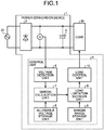
- FIG. 1 is a diagram illustrating a configuration of a power conversion device 1 according to a first embodiment.
- the power conversion device 1 includes a rectifier circuit 2 that rectifies an alternating-current voltage supplied from an alternating-current power supply 20.
- FIG. 1 also illustrates the alternating-current power supply 20.
- a terminal on an input side of the rectifier circuit 2 is connected to the alternating-current power supply 20, and the rectifier circuit 2 rectifies the alternating-current voltage supplied from the alternating-current power supply 20 into a direct-current voltage and outputs the direct-current voltage.
- the power conversion device 1 further includes a smoothing capacitor 3 connected to a terminal on an output side of the rectifier circuit 2.
- An example of the smoothing capacitor 3 is an electrolytic capacitor.
- the smoothing capacitor 3 smooths a direct-current voltage which has been rectified by the rectifier circuit 2 and includes a ripple voltage.
- the direct-current voltage, in which the ripple voltage has been decreased by the smoothing capacitor 3 as compared to that when the direct-current voltage from the rectifier circuit 2 was supplied to the smoothing capacitor 3, is supplied from the smoothing capacitor 3 to a load 30 that operates on the basis of the direct-current voltage.
- FIG. 1 also illustrates the load 30.
- the power conversion device 1 further includes a control unit 4 that controls an operation of the load 30.
- the control unit 4 includes a voltage detection unit 5 that detects the direct-current voltage rectified by the rectifier circuit 2, and an allowable voltage storage unit 6 that stores an allowable voltage upper limit value and an allowable voltage lower limit value of the direct-current voltage used when controlling the operation of the load 30.
- the allowable voltage upper limit value is an upper limit value in an allowable range of the direct-current voltage when the load 30 operates stably.
- the allowable voltage lower limit value is a lower limit value in the allowable range of the direct-current voltage. In the first embodiment, the allowable voltage upper limit value and the allowable voltage lower limit value are both constant.
- the control unit 4 further includes a margin calculation unit 7 that calculates an upper limit voltage difference which is a value obtained by subtracting a maximum value of the direct-current voltage detected by the voltage detection unit 5 from the allowable voltage upper limit value stored in the allowable voltage storage unit 6.
- the margin calculation unit 7 further calculates a lower limit voltage difference which is a value obtained by subtracting the allowable voltage lower limit value stored in the allowable voltage storage unit 6 from a minimum value of the direct-current voltage detected by the voltage detection unit 5.
- the margin calculation unit 7 decides that one of the calculated upper limit voltage difference and lower limit voltage difference which has a smaller value is a direct-current voltage margin.
- the control unit 4 further includes a margin range storage unit 8 that stores a plurality of margin ranges for stepwise limiting the operation of the load 30 depending on the direct-current voltage margin.
- the control unit 4 further includes a load limitation decision unit 9 that decides a limitation on the operation of the load 30 depending on a margin range including the direct-current voltage margin decided by the margin calculation unit 7 among the plurality of margin ranges stored in the margin range storage unit 8.
- the control unit 4 further includes a load control unit 10 that controls the operation of the load 30 depending on the limitation decided by the load limitation decision unit 9.
- the allowable voltage storage unit 6 and the margin range storage unit 8 are each, for example, a non-volatile or volatile semiconductor memory such as a random access memory (RAM), a read only memory (ROM), a flash memory, an erasable programmable read only memory (EPROM), or an electrically erasable programmable read only memory (EEPROM); a magnetic disk; a flexible disk; an optical disk; a compact disc; a mini disk; a digital versatile disk (DVD); or the like.
- RAM random access memory
- ROM read only memory
- EPROM erasable programmable read only memory
- EEPROM electrically erasable programmable read only memory
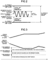
- FIG. 2 is a diagram for explaining an operation of the margin calculation unit 7 when the margin calculation unit 7 included in the power conversion device 1 according to the first embodiment decides the direct-current voltage margin.
- the margin calculation unit 7 detects a maximum value and a minimum value of the direct-current voltage detected by the voltage detection unit 5. Next, the margin calculation unit 7 reads the allowable voltage upper limit value and the allowable voltage lower limit value from the allowable voltage storage unit 6.
- the margin calculation unit 7 calculates the upper limit voltage difference which is a value obtained by subtracting the maximum value of the direct-current voltage from the allowable voltage upper limit value, and calculates the lower limit voltage difference which is a value obtained by subtracting the allowable voltage lower limit value from the minimum value of the direct-current voltage.
- the margin calculation unit 7 decides that one of the calculated upper limit voltage difference and lower limit voltage difference which has a smaller value is the direct-current voltage margin.
- a range from the allowable voltage lower limit value to the allowable voltage upper limit value is an allowable voltage range for operating the load 30.
- FIG. 3 is a diagram illustrating an example of changes with time of power consumption of the load 30 and the direct-current voltage margin when the power conversion device 1 according to the first embodiment controls the operation of the load 30, and a first margin range, a second margin range, and a third margin range stored in the margin range storage unit 8 included in the power conversion device 1.
- reference character "t" indicates time.
- the first margin range, the second margin range, and the third margin range illustrated in FIG. 3 are an example of the plurality of margin ranges.
- Each of the margin ranges is a range set to limit stepwise the operation of the load 30 depending on the direct-current voltage margin.
- the margin range storage unit 8 further stores a first margin threshold, a second margin threshold, and a third margin threshold for specifying the first margin range, the second margin range, and the third margin range.
- the first margin threshold is larger than the second margin threshold
- the second margin threshold is larger than the third margin threshold.
- the first margin threshold is 20 V
- the second margin threshold is 10 V
- the third margin threshold is 0 V.
- the first margin range is a range in which all values included in the first margin range are equal to or smaller than the first margin threshold and larger than the second margin threshold.
- the second margin range is a range in which all values included in the second margin range are equal to or smaller than the second margin threshold and larger than the third margin threshold.
- the third margin range is a range in which all values included in the third margin range are equal to or smaller than the third margin threshold.
- the load limitation decision unit 9 decides the limitation on the operation of the load 30 as follows. That is, when the direct-current voltage margin decided by the margin calculation unit 7 is included in the first margin range, the load limitation decision unit 9 decides a limitation for prohibiting an increase in the operation of the load 30. That is, the first margin range is a load increase prohibition range.
- the load limitation decision unit 9 decides a limitation for decreasing the operation of the load 30 when the direct-current voltage margin is included in the second margin range. That is, the second margin range is a load decrease range.
- the load limitation decision unit 9 decides a limitation for further suppressing the operation of the load 30 than in a case where the direct-current voltage margin is included in the first margin range.
- the load limitation decision unit 9 decides a limitation for stopping the operation of the load 30 when the direct-current voltage margin is included in the third margin range. That is, the third margin range is a load stop range. Furthermore, when the direct-current voltage margin is included in the third margin range, the load limitation decision unit 9 decides a limitation for further suppressing the operation of the load 30 than in a case where the direct-current voltage margin is included in the second margin range. The load limitation decision unit 9 decides to operate the load 30 normally without limiting the operation thereof when the direct-current voltage margin is larger than the first margin threshold. A cycle of deciding the direct-current voltage margin is set by a user of the power conversion device 1 and the load 30. A cycle of deciding the limitation is also set by the user.
- the load control unit 10 controls the operation of the load 30 depending on the limitation decided by the load limitation decision unit 9. For example, in a case where the load 30 is a motor, the load control unit 10 changes the number of revolutions per unit time of the motor depending on the limitation decided by the load limitation decision unit 9. For example, in a case where the load 30 is a variable resistor, the load control unit 10 changes a value of resistance depending on the limitation decided by the load limitation decision unit 9.
- the load control unit 10 performs control so as not to increase the number of revolutions per unit time of the motor when the direct-current voltage margin decided by the margin calculation unit 7 is included in the first margin range.
- the load control unit 10 reduces the number of revolutions per unit time of the motor when the direct-current voltage margin is included in the second margin range.
- the load control unit 10 stops the rotation of the motor when the direct-current voltage margin is included in the third margin range.
- an operation of the compressor motor may be affected by a configuration of a refrigerant circuit.
- the power conversion device 1 reduces the number of revolutions per unit time of the compressor motor, to thereby suppress a burden on the compressor motor when the direct-current voltage margin is included in the second margin range.
- the power conversion device 1 reduces the number of revolutions per unit time of the compressor motor when the direct-current voltage margin is included in the second margin range. Even when the number of revolutions per unit time is reduced, a decrease in the burden on the compressor may be delayed. That is, there may be concern about an undershoot of the direct-current voltage margin. In response to such a case, it is preferable that one or both of an interval between the first margin threshold and the second margin threshold and an interval between the second margin threshold and the third margin threshold be set relatively large.
- the margin calculation unit 7 calculates the upper limit voltage difference which is a value obtained by subtracting the maximum value of the direct-current voltage detected by the voltage detection unit 5 from the allowable voltage upper limit value stored in the allowable voltage storage unit 6, and calculates the lower limit voltage difference which is a value obtained by subtracting the allowable voltage lower limit value stored in the allowable voltage storage unit 6 from the minimum value of the direct-current voltage detected by the voltage detection unit 5.
- a difference between the maximum value and the minimum value of the direct-current voltage detected by the voltage detection unit 5 is the ripple voltage.
- the margin calculation unit 7 decides that one of the calculated upper limit voltage difference and lower limit voltage difference which has a smaller value is the direct-current voltage margin.
- the load limitation decision unit 9 decides a limitation on the operation of the load 30 depending on a margin range including the direct-current voltage margin decided by the margin calculation unit 7 among the margin ranges stored in the margin range storage unit 8.
- the load control unit 10 controls the operation of the load 30 depending on the limitation decided by the load limitation decision unit 9.
- the operation of the load 30 operating on the basis of the direct-current voltage including the ripple voltage can be controlled depending on the magnitude of the ripple voltage. Furthermore, in the power conversion device 1, the operation of the load 30 can be controlled stepwise depending on the magnitude of the ripple voltage.
- the power conversion device 1 controls the operation of the load 30 depending on the magnitude of the ripple voltage, a ripple removal capability of the smoothing capacitor 3 can be maximized in real time, and the rectified direct-current voltage can be held in a voltage range for stable operation of the load 30.
- the operation of the load 30 may be limited in a state where the ripple removal capability of the smoothing capacitor 3 is low.
- the power conversion device 1 can release the limitation on the load 30. That is, the power conversion device 1 can operate the load 30 stably even when the load 30 starts operating in a relatively low temperature environment.
- the power conversion device 1 controls stepwise the operation of the load 30 depending on the magnitude of the ripple voltage, even when the ripple removal capability of the smoothing capacitor 3 falls below previously assumed capability, the power conversion device 1 can control the operation of the load 30 appropriately.
- the load 30 is a compressor motor of an air conditioner
- the power conversion device 1 can avoid a situation where the compressor motor does not operate completely.
- both the maximum value and the minimum value of the direct-current voltage detected by the voltage detection unit 5 are constant. However, the minimum value of the direct-current voltage changes depending on the magnitude of a primary current flowing from the alternating-current power supply 20 to the rectifier circuit 2.
- FIG. 4 is a diagram illustrating that the minimum value of the direct-current voltage detected by the voltage detection unit 5 included in the power conversion device 1 according to the first embodiment decreases in proportion to the magnitude of the primary current.
- the margin calculation unit 7 calculates the lower limit voltage difference which is a value obtained by subtracting the allowable voltage lower limit value stored in the allowable voltage storage unit 6 from the minimum value of the direct-current voltage detected by the voltage detection unit 5.
- FIG. 5 is a diagram illustrating a processing circuit 51 when at least a part of components constituting the voltage detection unit 5, the margin calculation unit 7, the load limitation decision unit 9, and the load control unit 10 included in the power conversion device 1 according to the first embodiment is realized by the processing circuit 51. That is, at least a part of functions of the voltage detection unit 5, the margin calculation unit 7, the load limitation decision unit 9, and the load control unit 10 may be realized by the processing circuit 51.
- the processing circuit 51 is dedicated hardware.
- the processing circuit 51 is, for example, a single circuit, a composite circuit, a programmed processor, a parallel programmed processor, an application specific integrated circuit (ASIC), a field-programmable gate array (FPGA), or a combination thereof.
- a part of the voltage detection unit 5, the margin calculation unit 7, the load limitation decision unit 9, and the load control unit 10 may be dedicated hardware separate from the rest.
- FIG. 6 is a diagram illustrating a processor 61 when at least a part of functions of the voltage detection unit 5, the margin calculation unit 7, the load limitation decision unit 9, and the load control unit 10 included in the power conversion device 1 according to the first embodiment is realized by the processor 61. That is, at least a part of the functions of the voltage detection unit 5, the margin calculation unit 7, the load limitation decision unit 9, and the load control unit 10 may be realized by the processor 61 executing programs stored in a memory 62.
- the processor 61 is a central processing unit (CPU), a processing device, an arithmetic device, a microprocessor, a microcomputer, or a digital signal processor (DSP).
- FIG. 6 also illustrates the memory 62.
- the part of the functions of the voltage detection unit 5, the margin calculation unit 7, the load limitation decision unit 9, and the load control unit 10 is realized by the processor 61
- the part of the functions is realized by a combination of the processor 61 with software, firmware, or software and firmware.
- the software or the firmware is described as a program and stored in the memory 62.
- the processor 61 realizes at least a part of the functions of the voltage detection unit 5, the margin calculation unit 7, the load limitation decision unit 9, and the load control unit 10.
- the power conversion device 1 includes the memory 62 for storing programs with which steps executed by a part of the voltage detection unit 5, the margin calculation unit 7, the load limitation decision unit 9, and the load control unit 10 are executed as a result. It can also be said that the programs stored in the memory 62 cause a computer to execute a procedure or method executed by a part of the voltage detection unit 5, the margin calculation unit 7, the load limitation decision unit 9, and the load control unit 10.
- the memory 62 is, for example, a non-volatile or volatile semiconductor memory such as a RAM, a ROM, a flash memory, an EPROM, or an EEPROM; a magnetic disk; a flexible disk; an optical disk; a compact disc; a mini disk; a DVD; or the like.
- a part of the functions may be realized by dedicated hardware, and the rest of the functions may be realized by software or firmware.
- the functions of the voltage detection unit 5, the margin calculation unit 7, the load limitation decision unit 9, and the load control unit 10 can be realized by hardware, software, firmware, or a combination thereof.
- FIG. 7 is a diagram illustrating a configuration of a power conversion device 1A according to a second embodiment.
- the power conversion device 1A includes the rectifier circuit 2, the smoothing capacitor 3, the voltage detection unit 5, the margin range storage unit 8, the load limitation decision unit 9, and the load control unit 10 included in the power conversion device 1 according to the first embodiment.
- the control unit 4 of the first embodiment is replaced with a control unit 4A.
- differences from the first embodiment will be mainly described.
- the power conversion device 1A further includes a primary current detection unit 11 that detects a primary current flowing from the alternating-current power supply 20 to the rectifier circuit 2.
- the primary current detection unit 11 is connected to a terminal on an input side of the rectifier circuit 2.
- the primary current detection unit 11 is included in the control unit 4A that includes the voltage detection unit 5, the margin range storage unit 8, the load limitation decision unit 9, and the load control unit 10.
- the allowable voltage storage unit 6 of the first embodiment is replaced with an allowable voltage storage unit 6A.
- the allowable voltage storage unit 6A is included in the control unit 4A.
- the allowable voltage storage unit 6A stores an allowable voltage upper limit value and an allowable voltage lower limit value for each of a plurality of primary currents. That is, the allowable voltage storage unit 6A stores a plurality of sets of the allowable voltage upper limit value and the allowable voltage lower limit value, and the plurality of sets correspond to the plurality of primary currents.
- the allowable voltage storage unit 6A is, for example, a nonvolatile or volatile semiconductor memory such as a RAM, a ROM, a flash memory, an EPROM, or an EEPROM; a magnetic disk; a flexible disk; an optical disk; a compact disc; a mini disk; a DVD; or the like.
- FIG. 8 is a diagram illustrating an example of the allowable voltage upper limit value and the allowable voltage lower limit value stored in the allowable voltage storage unit 6A included in the power conversion device 1A according to the second embodiment.
- the allowable voltage upper limit value and the allowable voltage lower limit value are both constant.
- the allowable voltage upper limit value is constant regardless of the primary current, but the allowable voltage lower limit value increases as the primary current increases.
- the allowable voltage lower limit value is directly proportional to the magnitude of the primary current.
- the margin calculation unit 7 of the first embodiment is replaced with a margin calculation unit 7A.
- the margin calculation unit 7A is included in the control unit 4A.
- the margin calculation unit 7A calculates the upper limit voltage difference and the lower limit voltage difference using an allowable voltage upper limit value and an allowable voltage lower limit value of a set corresponding to the primary current detected by the primary current detection unit 11 among the plurality of sets of the allowable voltage upper limit value and the allowable voltage lower limit value stored in the allowable voltage storage unit 6A.
- the margin calculation unit 7A decides that one of the calculated upper limit voltage difference and lower limit voltage difference which has a smaller value is the direct-current voltage margin.
- the power conversion device 1A calculates the upper limit voltage difference and the lower limit voltage difference using the allowable voltage upper limit value and the allowable voltage lower limit value of the set corresponding to the primary current detected by the primary current detection unit 11. That is, the power conversion device 1A can control the operation of the load 30 depending on the magnitude of the ripple voltage in consideration of the primary current.
- the minimum values of the direct-current voltage corresponding to the capacitance of the smoothing capacitor 3 are each indicated by a broken line.
- a first broken line L1 an example of the minimum value of the direct-current voltage when the capacitance of the smoothing capacitor 3 is relatively large is indicated by a first broken line L1
- a second broken line L2 an example of the minimum value of the direct-current voltage when the capacitance of the smoothing capacitor 3 is relatively medium is indicated by a second broken line L2
- an example of the minimum value of the direct-current voltage when the capacitance of the smoothing capacitor 3 is relatively small is indicated by a third broken line L3.
- a character string "smoothing capacitor (large)” is added to the first broken line L1
- a character string “smoothing capacitor (medium)” is added to the second broken line L2
- a character string “smoothing capacitor (small)” is added to the third broken line L3.
- Cross points between a solid line and the broken lines in FIG. 8 are each a point at which the direct-current voltage margin decided by the margin calculation unit 7A becomes 0 V.
- the direct-current voltage of the smoothing capacitor 3 decreases as the primary current increases regardless of the capacitance.
- the allowable voltage storage unit 6A stores the allowable voltage upper limit value and the allowable voltage lower limit value for each of the plurality of primary currents.
- At least a part of functions of the voltage detection unit 5, the margin calculation unit 7A, the load limitation decision unit 9, the load control unit 10, and the primary current detection unit 11 included in the power conversion device 1A according to the second embodiment may be realized by a processing circuit having the same function as the processing circuit 51 described in the first embodiment.
- At least a part of the functions of the voltage detection unit 5, the margin calculation unit 7A, the load limitation decision unit 9, the load control unit 10, and the primary current detection unit 11 may be realized by a processor having the same function as the processor 61 described in the first embodiment.
- the power conversion device 1A includes a memory for storing programs with which steps executed by at least a part of the voltage detection unit 5, the margin calculation unit 7A, the load limitation decision unit 9, the load control unit 10, and the primary current detection unit 11 are executed as a result.
- the memory is a memory having the same function as the memory 62 described in the first embodiment.
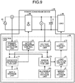
- FIG. 9 is a diagram illustrating a configuration of a power conversion device 1B according to a third embodiment.
- the power conversion device 1B includes the smoothing capacitor 3, the voltage detection unit 5, the allowable voltage storage unit 6A, the margin calculation unit 7A, the margin range storage unit 8, the load limitation decision unit 9, the load control unit 10, and the primary current detection unit 11 included in the power conversion device 1A according to the second embodiment.
- the power conversion device 1B includes, instead of the rectifier circuit 2 of the second embodiment, an active converter 2B having a function of boosting an alternating-current voltage to an arbitrary direct-current voltage.
- the control unit 4A of the second embodiment is replaced with a control unit 4B.
- differences from the second embodiment will be mainly described.
- the power conversion device 1B includes a ripple storage unit 12 that stores a ripple voltage range in a case where the smoothing capacitor 3 has been specified in advance to be normal for each of the plurality of primary currents.
- the ripple storage unit 12 is included in the control unit 4B that includes the voltage detection unit 5, the allowable voltage storage unit 6A, the margin calculation unit 7A, the margin range storage unit 8, the load limitation decision unit 9, the load control unit 10, and the primary current detection unit 11.
- the ripple storage unit 12 is, for example, a nonvolatile or volatile semiconductor memory such as a RAM, a ROM, a flash memory, an EPROM, or an EEPROM; a magnetic disk; a flexible disk; an optical disk; a compact disc; a mini disk; a DVD; or the like.
- the power conversion device 1B further includes a capacitor determination unit 13 that determines whether the smoothing capacitor 3 is normal.
- the capacitor determination unit 13 is included in the control unit 4B.
- the capacitor determination unit 13 calculates a ripple voltage from the direct-current voltage detected by the voltage detection unit 5. Specifically, the capacitor determination unit 13 calculates the ripple voltage by subtracting, from a maximum value of the direct-current voltage detected by the voltage detection unit 5, a minimum value thereof.
- the capacitor determination unit 13 determines whether the smoothing capacitor 3 is normal by comparing the ripple voltage range corresponding to the primary current detected by the primary current detection unit 11 among a plurality of ripple voltage ranges stored in the ripple storage unit 12 with the calculated ripple voltage. Specifically, the capacitor determination unit 13 determines whether the calculated ripple voltage is included in the ripple voltage range corresponding to the primary current detected by the primary current detection unit 11 among the plurality of ripple voltage ranges stored in the ripple storage unit 12, and when it is determined that the calculated ripple voltage is included in the ripple voltage range corresponding thereto, the capacitor determination unit 13 determines that the smoothing capacitor 3 is normal.
- the power conversion device 1B further includes an active converter control unit 14 that controls the active converter 2B.
- the active converter control unit 14 is included in the control unit 4B.
- the active converter control unit 14 causes the active converter 2B to perform a boosting operation only when it is determined by the capacitor determination unit 13 that the smoothing capacitor 3 is normal.
- the active converter 2B performs the boosting operation only when it is determined that the smoothing capacitor 3 is normal. That is, the power conversion device 1B can increase the voltage supplied to the load 30 only when the smoothing capacitor 3 is normal.
- FIG. 10 is a diagram illustrating a relationship between the primary current and the direct-current voltage when the active converter 2B included in the power conversion device 1B according to the third embodiment performs a boosting operation.
- a difference between the maximum value and the minimum value of the direct-current voltage detected by the voltage detection unit 5 increases as a value of the primary current detected by the primary current detection unit 11 increases. That is, when the active converter 2B performs the boosting operation, the ripple voltage increases as the value of the primary current increases. For example, when the active converter 2B performs the boosting operation, the ripple voltage is directly proportional to the magnitude of the primary current.
- the capacitor determination unit 13 can appropriately determine whether the smoothing capacitor 3 is normal.
- the active converter control unit 14 further has a function of determining whether there is a possibility that, in a case where the active converter 2B has started the boosting operation, a maximum value of the direct-current voltage including the ripple voltage after the boosting exceeds an upper limit value of the direct-current voltage which the load 30 is allowed to have, on the basis of whether the smoothing capacitor 3 is normal. Therefore, by the active converter 2B having started the boosting operation in a state where the capacitance of the smoothing capacitor 3 is low, the active converter control unit 14 can avoid a situation in which the allowable voltage upper limit value exceeds the maximum value of the direct-current voltage including the ripple voltage.
- the capacitor determination unit 13 has a function of determining whether the smoothing capacitor 3 has a capacitance characteristic capable of suppressing an overshoot of the direct-current voltage which is a concern immediately after the active converter 2B starts the boosting operation, on the basis of the ripple voltage and the primary current.
- the active converter control unit 14 constantly determines whether there is a possibility that, in a case where the active converter 2B has started the boosting operation, the maximum value of the direct-current voltage including the ripple voltage after the boosting exceeds the upper limit value of the direct-current voltage which the load 30 is allowed to have. Consequently, in a case where the load 30 is actuated under a relatively low temperature environment and then the temperature around the smoothing capacitor 3 rises and the smoothing capacitor 3 recovers to a normal state, the active converter control unit 14 can cause the active converter 2B to perform the boosting operation at a point of time when the smoothing capacitor 3 recovers to the normal state.
- the smoothing capacitor 3 recovers to the normal state is when the smoothing capacitor 3 recovers to a state where the smoothing capacitor 3 can suppress the overshoot of the direct-current voltage.
- At least a part of functions of the voltage detection unit 5, the margin calculation unit 7A, the load limitation decision unit 9, the load control unit 10, the primary current detection unit 11, the capacitor determination unit 13, and the active converter control unit 14 included in the power conversion device 1B according to the third embodiment may be realized by a processing circuit having the same function as the processing circuit 51 described in the first embodiment.
- At least a part of the functions of the voltage detection unit 5, the margin calculation unit 7A, the load limitation decision unit 9, the load control unit 10, the primary current detection unit 11, the capacitor determination unit 13, and the active converter control unit 14 may be realized by a processor having the same function as the processor 61 described in the first embodiment.
- the power conversion device 1B includes a memory for storing programs with which steps executed by at least a part of the voltage detection unit 5, the margin calculation unit 7A, the load limitation decision unit 9, the load control unit 10, the primary current detection unit 11, the capacitor determination unit 13, and the active converter control unit 14 are executed as a result.
- the memory is a memory having the same function as the memory 62 described in the first embodiment.
- FIG. 11 is a diagram illustrating a configuration of a power conversion device 1C according to a fourth embodiment.
- the power conversion device 1C includes the active converter 2B, the smoothing capacitor 3, the voltage detection unit 5, the allowable voltage storage unit 6A, the margin calculation unit 7A, the margin range storage unit 8, the load limitation decision unit 9, the load control unit 10, the primary current detection unit 11, the ripple storage unit 12, the capacitor determination unit 13, and the active converter control unit 14 included in the power conversion device 1B according to the third embodiment.
- the control unit 4B of the third embodiment is replaced with a control unit 4C.
- differences from the third embodiment will be mainly described.
- the power conversion device 1C further includes an abnormality detection unit 15 that determines that an abnormality has occurred when the capacitor determination unit 13 does not determine that the smoothing capacitor 3 is normal continuously in a predetermined period.
- the abnormality detection unit 15 determines that an abnormality has occurred also when the load limitation decision unit 9 decides to limit the operation of the load 30 continuously in a predetermined period.
- the abnormality detection unit 15 is included in the control unit 4C that includes the voltage detection unit 5, the allowable voltage storage unit 6A, the margin calculation unit 7A, the margin range storage unit 8, the load limitation decision unit 9, the load control unit 10, the primary current detection unit 11, the ripple storage unit 12, the capacitor determination unit 13, and the active converter control unit 14.
- the power conversion device 1C further includes an abnormality notification unit 16 that, when the abnormality detection unit 15 determines that an abnormality has occurred, notifies the outside of the power conversion device 1C that the abnormality has occurred.
- An example of the abnormality notification unit 16 is a display device that displays that an abnormality has occurred.
- Another example of the abnormality notification unit 16 is a speaker that notifies by sound that an abnormality has occurred.
- the power conversion device 1C determines that an abnormality has occurred when the smoothing capacitor 3 is not normal or the operation of the load 30 is limited continuously in a predetermined period, and notifies the outside of the power conversion device 1C that the abnormality has occurred.
- a user can cope with the abnormality by being notified that the abnormality has occurred. For example, the user can take measures to replace the active converter 2B or the smoothing capacitor 3 with a normal one. That is, when an abnormality occurs, the power conversion device 1C enables the user to take measures to the abnormality early. Furthermore, the power conversion device 1C can shorten a period during which the load 30 cannot operate.
- the power conversion device 1C determines that an abnormality has occurred when the smoothing capacitor 3 is not normal or the operation of the load 30 is limited continuously in a predetermined period. Since the predetermined period is set, the power conversion device 1C can determine that, for example, an unstable state immediately after the load 30 starts the operation in a relatively low temperature environment is not abnormal.
- the abnormality detection unit 15 may decide the content of the abnormality depending on the degree of limitation or a period of limitation when the operation of the load 30 is limited. In that case, the abnormality notification unit 16 also notifies the outside of the power conversion device 1C of the content of the abnormality decided by the abnormality detection unit 15. The user can take more appropriate measures to the abnormality by being notified of the content of the abnormality.
- the smoothing capacitor 3 may be a capacitor which is more excellent in a function of being less prone to deterioration with age than in a function of suppressing the ripple voltage.
- At least a part of functions of the voltage detection unit 5, the margin calculation unit 7A, the load limitation decision unit 9, the load control unit 10, the primary current detection unit 11, the capacitor determination unit 13, the active converter control unit 14, the abnormality detection unit 15, and the abnormality notification unit 16 included in the power conversion device 1C according to the fourth embodiment may be realized by a processing circuit having the same function as the processing circuit 51 described in the first embodiment.
- At least a part of the functions of the voltage detection unit 5, the margin calculation unit 7A, the load limitation decision unit 9, the load control unit 10, the primary current detection unit 11, the capacitor determination unit 13, the active converter control unit 14, the abnormality detection unit 15, and the abnormality notification unit 16 may be realized by a processor having the same function as the processor 61 described in the first embodiment.
- the power conversion device 1C includes a memory for storing programs with which steps executed by at least a part of the voltage detection unit 5, the margin calculation unit 7A, the load limitation decision unit 9, the load control unit 10, the primary current detection unit 11, the capacitor determination unit 13, the active converter control unit 14, the abnormality detection unit 15, and the abnormality notification unit 16 are executed as a result.
- the memory is a memory having the same function as the memory 62 described in the first embodiment.
- 1, 1A, 1B, 1C power conversion device 2 rectifier circuit; 2B active converter; 3 smoothing capacitor; 4, 4A, 4B, 4C control unit; 5 voltage detection unit; 6, 6A allowable voltage storage unit; 7, 7A margin calculation unit; 8 margin range storage unit; 9 load limitation decision unit; 10 load control unit; 11 primary current detection unit; 12 ripple storage unit; 13 capacitor determination unit; 14 active converter control unit; 15 abnormality detection unit; 16 abnormality notification unit; 20 alternating-current power supply; 30 load; 51 processing circuit; 61 processor; 62 memory.
Landscapes
- Engineering & Computer Science (AREA)
- Power Engineering (AREA)
- Dc-Dc Converters (AREA)
- Rectifiers (AREA)
- Power Conversion In General (AREA)
Abstract
Description
- The present invention relates to a power conversion device that obtains a direct-current voltage by rectifying an alternating-current voltage and controls an operation of a load that operates on the basis of the direct-current voltage.
- A power conversion device is conventionally used which obtains a direct-current voltage by rectifying an alternating-current voltage and controls an operation of a load that operates on the basis of the direct-current voltage. In the power conversion device, a smoothing capacitor is used which smooths a ripple voltage generated when obtaining the direct-current voltage by rectifying the alternating-current voltage. An example of the smoothing capacitor is an electrolytic capacitor. Because electrolytic capacitors change in characteristics due to ambient temperature or aging, techniques for coping with the change in characteristics have been proposed.
- For example, a technique has been proposed with which, in order to cope with a decrease in a smoothing ability of an electrolytic capacitor due to a decrease in capacitance and an increase in equivalent series resistance when the electrolytic capacitor is used at a relatively low temperature, an operation of a load is limited for a certain period of time from when the load starts the operation up to when it is assumed that the electrolytic capacitor warms and the smoothing ability thereof recovers (see, for example, Patent Literature 1).
- A method has also been proposed with which, in order to prevent a safety valve from operating due to a decrease in capacitance of an electrolytic capacitor depending on a period of use, power is supplied to a load depending on the magnitude of a ripple voltage included in a direct-current voltage obtained by performing rectification (see, for example, Patent Literature 2).
-
- Patent Literature 1: Japanese Patent No.
5925425 - Patent Literature 2: Japanese Patent Application Laid-open No.
2012-23891 - However, with regard to the technique described in Patent Literature 1, since the certain period of time up to when it is assumed that the electrolytic capacitor warms and the smoothing ability thereof recovers is decided by a plurality of factors, the certain period of time cannot be easily decided. The method with which power is supplied to the load depending on the magnitude of the ripple voltage described in Patent Literature 2 cannot be applied to a power conversion device in which the power supplied to the load cannot be easily changed. That is, in the prior art, the operation of the load operating on the basis of the direct-current voltage including the ripple voltage cannot be appropriately controlled depending on the magnitude of the ripple voltage.
- The present invention has been made in view of the above, and it is an object of the present invention to obtain a power conversion device that controls an operation of a load that operates on the basis of a direct-current voltage including a ripple voltage depending on the magnitude of the ripple voltage.
- To solve the problem and achieve the object described above, a power conversion device according to the present invention includes: a rectifier circuit that rectifies an alternating-current voltage supplied from an alternating-current power supply; a smoothing capacitor that smooths a direct-current voltage that has been rectified by the rectifier circuit, the direct-current voltage including a ripple voltage; a voltage detection unit that detects the direct-current voltage rectified by the rectifier circuit; an allowable voltage storage unit that stores an allowable voltage upper limit value and an allowable voltage lower limit value of a direct-current voltage used when controlling an operation of a load that operates on the basis of the direct-current voltage smoothed by the smoothing capacitor; a margin calculation unit that calculates an upper limit voltage difference that is a value obtained by subtracting a maximum value of the direct-current voltage detected by the voltage detection unit from the allowable voltage upper limit value stored in the allowable voltage storage unit, and a lower limit voltage difference that is a value obtained by subtracting the allowable voltage lower limit value stored in the allowable voltage storage unit from a minimum value of the direct-current voltage detected by the voltage detection unit, and that decides that one of the upper limit voltage difference and the lower limit voltage difference that has a smaller value is a direct-current voltage margin; a margin range storage unit that stores a plurality of margin ranges for stepwise limiting the operation of the load; a load limitation decision unit that decides a limitation on the operation of the load depending on a margin range including the direct-current voltage margin decided by the margin calculation unit among the plurality of margin ranges stored in the margin range storage unit; and a load control unit that controls the operation of the load depending on the limitation decided by the load limitation decision unit.
- The power conversion device according to the present invention achieves an effect of controlling an operation of a load that operates on the basis of a direct-current voltage including a ripple voltage depending on the magnitude of the ripple voltage.
-
-
FIG. 1 is a diagram illustrating a configuration of a power conversion device according to a first embodiment. -
FIG. 2 is a diagram for explaining an operation of a margin calculation unit included in the power conversion device according to the first embodiment when the margin calculation unit decides a direct-current voltage margin. -
FIG. 3 is a diagram illustrating an example of changes with time of power consumption of a load and the direct-current voltage margin when the power conversion device according to the first embodiment controls an operation of the load, and a first margin range, a second margin range, and a third margin range stored in a margin range storage unit included in the power conversion device. -
FIG. 4 is a diagram illustrating that a minimum value of a direct-current voltage detected by a voltage detection unit included in the power conversion device according to the first embodiment decreases in proportion to the magnitude of a primary current. -
FIG. 5 is a diagram illustrating a processing circuit when at least a part of components constituting the voltage detection unit, the margin calculation unit, a load limitation decision unit, and a load control unit included in the power conversion device according to the first embodiment is realized by the processing circuit. -
FIG. 6 is a diagram illustrating a processor when at least a part of functions of the voltage detection unit, the margin calculation unit, the load limitation decision unit, and the load control unit included in the power conversion device according to the first embodiment is realized by the processor. -
FIG. 7 is a diagram illustrating a configuration of a power conversion device according to a second embodiment. -
FIG. 8 is a diagram illustrating an example of an allowable voltage upper limit value and an allowable voltage lower limit value stored in an allowable voltage storage unit included in the power conversion device according to the second embodiment. -
FIG. 9 is a diagram illustrating a configuration of a power conversion device according to a third embodiment. -
FIG. 10 is a diagram illustrating a relationship between a primary current and a direct-current voltage when an active converter included in the power conversion device according to the third embodiment performs a boosting operation. -
FIG. 11 is a diagram illustrating a configuration of a power conversion device according to a fourth embodiment. - Hereinafter, a power conversion device according to each embodiment of the present invention will be described in detail with reference to the drawings. The present invention is not limited to the embodiments.
-
FIG. 1 is a diagram illustrating a configuration of a power conversion device 1 according to a first embodiment. The power conversion device 1 includes a rectifier circuit 2 that rectifies an alternating-current voltage supplied from an alternating-current power supply 20.FIG. 1 also illustrates the alternating-current power supply 20. A terminal on an input side of the rectifier circuit 2 is connected to the alternating-current power supply 20, and the rectifier circuit 2 rectifies the alternating-current voltage supplied from the alternating-current power supply 20 into a direct-current voltage and outputs the direct-current voltage. - The power conversion device 1 further includes a
smoothing capacitor 3 connected to a terminal on an output side of the rectifier circuit 2. An example of thesmoothing capacitor 3 is an electrolytic capacitor. Thesmoothing capacitor 3 smooths a direct-current voltage which has been rectified by the rectifier circuit 2 and includes a ripple voltage. The direct-current voltage, in which the ripple voltage has been decreased by thesmoothing capacitor 3 as compared to that when the direct-current voltage from the rectifier circuit 2 was supplied to thesmoothing capacitor 3, is supplied from thesmoothing capacitor 3 to a load 30 that operates on the basis of the direct-current voltage.FIG. 1 also illustrates the load 30. - The power conversion device 1 further includes a control unit 4 that controls an operation of the load 30. The control unit 4 includes a
voltage detection unit 5 that detects the direct-current voltage rectified by the rectifier circuit 2, and an allowablevoltage storage unit 6 that stores an allowable voltage upper limit value and an allowable voltage lower limit value of the direct-current voltage used when controlling the operation of the load 30. The allowable voltage upper limit value is an upper limit value in an allowable range of the direct-current voltage when the load 30 operates stably. The allowable voltage lower limit value is a lower limit value in the allowable range of the direct-current voltage. In the first embodiment, the allowable voltage upper limit value and the allowable voltage lower limit value are both constant. - The control unit 4 further includes a
margin calculation unit 7 that calculates an upper limit voltage difference which is a value obtained by subtracting a maximum value of the direct-current voltage detected by thevoltage detection unit 5 from the allowable voltage upper limit value stored in the allowablevoltage storage unit 6. Themargin calculation unit 7 further calculates a lower limit voltage difference which is a value obtained by subtracting the allowable voltage lower limit value stored in the allowablevoltage storage unit 6 from a minimum value of the direct-current voltage detected by thevoltage detection unit 5. Themargin calculation unit 7 decides that one of the calculated upper limit voltage difference and lower limit voltage difference which has a smaller value is a direct-current voltage margin. - The control unit 4 further includes a margin
range storage unit 8 that stores a plurality of margin ranges for stepwise limiting the operation of the load 30 depending on the direct-current voltage margin. The control unit 4 further includes a loadlimitation decision unit 9 that decides a limitation on the operation of the load 30 depending on a margin range including the direct-current voltage margin decided by themargin calculation unit 7 among the plurality of margin ranges stored in the marginrange storage unit 8. The control unit 4 further includes a load control unit 10 that controls the operation of the load 30 depending on the limitation decided by the loadlimitation decision unit 9. - The allowable
voltage storage unit 6 and the marginrange storage unit 8 are each, for example, a non-volatile or volatile semiconductor memory such as a random access memory (RAM), a read only memory (ROM), a flash memory, an erasable programmable read only memory (EPROM), or an electrically erasable programmable read only memory (EEPROM); a magnetic disk; a flexible disk; an optical disk; a compact disc; a mini disk; a digital versatile disk (DVD); or the like. -
FIG. 2 is a diagram for explaining an operation of themargin calculation unit 7 when themargin calculation unit 7 included in the power conversion device 1 according to the first embodiment decides the direct-current voltage margin. Themargin calculation unit 7 detects a maximum value and a minimum value of the direct-current voltage detected by thevoltage detection unit 5. Next, themargin calculation unit 7 reads the allowable voltage upper limit value and the allowable voltage lower limit value from the allowablevoltage storage unit 6. - The
margin calculation unit 7 calculates the upper limit voltage difference which is a value obtained by subtracting the maximum value of the direct-current voltage from the allowable voltage upper limit value, and calculates the lower limit voltage difference which is a value obtained by subtracting the allowable voltage lower limit value from the minimum value of the direct-current voltage. Themargin calculation unit 7 decides that one of the calculated upper limit voltage difference and lower limit voltage difference which has a smaller value is the direct-current voltage margin. A range from the allowable voltage lower limit value to the allowable voltage upper limit value is an allowable voltage range for operating the load 30. -
FIG. 3 is a diagram illustrating an example of changes with time of power consumption of the load 30 and the direct-current voltage margin when the power conversion device 1 according to the first embodiment controls the operation of the load 30, and a first margin range, a second margin range, and a third margin range stored in the marginrange storage unit 8 included in the power conversion device 1. InFIG. 3 , reference character "t" indicates time. - The first margin range, the second margin range, and the third margin range illustrated in
FIG. 3 are an example of the plurality of margin ranges. Each of the margin ranges is a range set to limit stepwise the operation of the load 30 depending on the direct-current voltage margin. The marginrange storage unit 8 further stores a first margin threshold, a second margin threshold, and a third margin threshold for specifying the first margin range, the second margin range, and the third margin range. The first margin threshold is larger than the second margin threshold, and the second margin threshold is larger than the third margin threshold. For example, the first margin threshold is 20 V, the second margin threshold is 10 V, and the third margin threshold is 0 V. - In the example of
FIG. 3 , the first margin range is a range in which all values included in the first margin range are equal to or smaller than the first margin threshold and larger than the second margin threshold. The second margin range is a range in which all values included in the second margin range are equal to or smaller than the second margin threshold and larger than the third margin threshold. The third margin range is a range in which all values included in the third margin range are equal to or smaller than the third margin threshold. - For example, the load
limitation decision unit 9 decides the limitation on the operation of the load 30 as follows. That is, when the direct-current voltage margin decided by themargin calculation unit 7 is included in the first margin range, the loadlimitation decision unit 9 decides a limitation for prohibiting an increase in the operation of the load 30. That is, the first margin range is a load increase prohibition range. The loadlimitation decision unit 9 decides a limitation for decreasing the operation of the load 30 when the direct-current voltage margin is included in the second margin range. That is, the second margin range is a load decrease range. Furthermore, when the direct-current voltage margin is included in the second margin range, the loadlimitation decision unit 9 decides a limitation for further suppressing the operation of the load 30 than in a case where the direct-current voltage margin is included in the first margin range. - The load
limitation decision unit 9 decides a limitation for stopping the operation of the load 30 when the direct-current voltage margin is included in the third margin range. That is, the third margin range is a load stop range. Furthermore, when the direct-current voltage margin is included in the third margin range, the loadlimitation decision unit 9 decides a limitation for further suppressing the operation of the load 30 than in a case where the direct-current voltage margin is included in the second margin range. The loadlimitation decision unit 9 decides to operate the load 30 normally without limiting the operation thereof when the direct-current voltage margin is larger than the first margin threshold. A cycle of deciding the direct-current voltage margin is set by a user of the power conversion device 1 and the load 30. A cycle of deciding the limitation is also set by the user. - The load control unit 10 controls the operation of the load 30 depending on the limitation decided by the load
limitation decision unit 9. For example, in a case where the load 30 is a motor, the load control unit 10 changes the number of revolutions per unit time of the motor depending on the limitation decided by the loadlimitation decision unit 9. For example, in a case where the load 30 is a variable resistor, the load control unit 10 changes a value of resistance depending on the limitation decided by the loadlimitation decision unit 9. - Specifically, in a case where the load 30 is a motor, the load control unit 10 performs control so as not to increase the number of revolutions per unit time of the motor when the direct-current voltage margin decided by the
margin calculation unit 7 is included in the first margin range. The load control unit 10 reduces the number of revolutions per unit time of the motor when the direct-current voltage margin is included in the second margin range. The load control unit 10 stops the rotation of the motor when the direct-current voltage margin is included in the third margin range. - In a case where the load 30 is a compressor motor mounted on an outdoor unit of an air conditioner, an operation of the compressor motor may be affected by a configuration of a refrigerant circuit. In a case where the operation of the compressor motor is affected by the configuration of the refrigerant circuit, the power conversion device 1 reduces the number of revolutions per unit time of the compressor motor, to thereby suppress a burden on the compressor motor when the direct-current voltage margin is included in the second margin range.
- In the case where the load 30 is the compressor motor mounted on the outdoor unit of the air conditioner, the power conversion device 1 reduces the number of revolutions per unit time of the compressor motor when the direct-current voltage margin is included in the second margin range. Even when the number of revolutions per unit time is reduced, a decrease in the burden on the compressor may be delayed. That is, there may be concern about an undershoot of the direct-current voltage margin. In response to such a case, it is preferable that one or both of an interval between the first margin threshold and the second margin threshold and an interval between the second margin threshold and the third margin threshold be set relatively large.
- As described above, in the power conversion device 1 according to the first embodiment, the
margin calculation unit 7 calculates the upper limit voltage difference which is a value obtained by subtracting the maximum value of the direct-current voltage detected by thevoltage detection unit 5 from the allowable voltage upper limit value stored in the allowablevoltage storage unit 6, and calculates the lower limit voltage difference which is a value obtained by subtracting the allowable voltage lower limit value stored in the allowablevoltage storage unit 6 from the minimum value of the direct-current voltage detected by thevoltage detection unit 5. A difference between the maximum value and the minimum value of the direct-current voltage detected by thevoltage detection unit 5 is the ripple voltage. - The
margin calculation unit 7 decides that one of the calculated upper limit voltage difference and lower limit voltage difference which has a smaller value is the direct-current voltage margin. The loadlimitation decision unit 9 decides a limitation on the operation of the load 30 depending on a margin range including the direct-current voltage margin decided by themargin calculation unit 7 among the margin ranges stored in the marginrange storage unit 8. The load control unit 10 controls the operation of the load 30 depending on the limitation decided by the loadlimitation decision unit 9. - That is, in the power conversion device 1, the operation of the load 30 operating on the basis of the direct-current voltage including the ripple voltage can be controlled depending on the magnitude of the ripple voltage. Furthermore, in the power conversion device 1, the operation of the load 30 can be controlled stepwise depending on the magnitude of the ripple voltage.
- In addition, since the power conversion device 1 controls the operation of the load 30 depending on the magnitude of the ripple voltage, a ripple removal capability of the smoothing
capacitor 3 can be maximized in real time, and the rectified direct-current voltage can be held in a voltage range for stable operation of the load 30. When the operation of the load 30 starts in a relatively low temperature environment, the operation of the load 30 may be limited in a state where the ripple removal capability of the smoothingcapacitor 3 is low. However, when the smoothingcapacitor 3 warms by lapse of time and the smoothing ability of the smoothingcapacitor 3 recovers, the power conversion device 1 can release the limitation on the load 30. That is, the power conversion device 1 can operate the load 30 stably even when the load 30 starts operating in a relatively low temperature environment. - Furthermore, since the power conversion device 1 controls stepwise the operation of the load 30 depending on the magnitude of the ripple voltage, even when the ripple removal capability of the smoothing
capacitor 3 falls below previously assumed capability, the power conversion device 1 can control the operation of the load 30 appropriately. - In the case where the load 30 is a compressor motor of an air conditioner, it takes a relatively long time for a temperature of air in a space where an indoor unit included in the air conditioner is provided to approach a set temperature when the operation of the compressor motor is limited. However, because the direct-current voltage is held within a range in which the compressor motor can operate stably, the power conversion device 1 can avoid a situation where the compressor motor does not operate completely.
- In
FIG. 2 , both the maximum value and the minimum value of the direct-current voltage detected by thevoltage detection unit 5 are constant. However, the minimum value of the direct-current voltage changes depending on the magnitude of a primary current flowing from the alternating-current power supply 20 to the rectifier circuit 2.FIG. 4 is a diagram illustrating that the minimum value of the direct-current voltage detected by thevoltage detection unit 5 included in the power conversion device 1 according to the first embodiment decreases in proportion to the magnitude of the primary current. Even when the minimum value of the direct-current voltage decreases in proportion to the magnitude of the primary current, themargin calculation unit 7 calculates the lower limit voltage difference which is a value obtained by subtracting the allowable voltage lower limit value stored in the allowablevoltage storage unit 6 from the minimum value of the direct-current voltage detected by thevoltage detection unit 5. -
FIG. 5 is a diagram illustrating aprocessing circuit 51 when at least a part of components constituting thevoltage detection unit 5, themargin calculation unit 7, the loadlimitation decision unit 9, and the load control unit 10 included in the power conversion device 1 according to the first embodiment is realized by theprocessing circuit 51. That is, at least a part of functions of thevoltage detection unit 5, themargin calculation unit 7, the loadlimitation decision unit 9, and the load control unit 10 may be realized by theprocessing circuit 51. - The
processing circuit 51 is dedicated hardware. Theprocessing circuit 51 is, for example, a single circuit, a composite circuit, a programmed processor, a parallel programmed processor, an application specific integrated circuit (ASIC), a field-programmable gate array (FPGA), or a combination thereof. A part of thevoltage detection unit 5, themargin calculation unit 7, the loadlimitation decision unit 9, and the load control unit 10 may be dedicated hardware separate from the rest. -
FIG. 6 is a diagram illustrating a processor 61 when at least a part of functions of thevoltage detection unit 5, themargin calculation unit 7, the loadlimitation decision unit 9, and the load control unit 10 included in the power conversion device 1 according to the first embodiment is realized by the processor 61. That is, at least a part of the functions of thevoltage detection unit 5, themargin calculation unit 7, the loadlimitation decision unit 9, and the load control unit 10 may be realized by the processor 61 executing programs stored in a memory 62. The processor 61 is a central processing unit (CPU), a processing device, an arithmetic device, a microprocessor, a microcomputer, or a digital signal processor (DSP).FIG. 6 also illustrates the memory 62. - When at least a part of the functions of the
voltage detection unit 5, themargin calculation unit 7, the loadlimitation decision unit 9, and the load control unit 10 is realized by the processor 61, the part of the functions is realized by a combination of the processor 61 with software, firmware, or software and firmware. The software or the firmware is described as a program and stored in the memory 62. By reading and executing the programs stored in the memory 62, the processor 61 realizes at least a part of the functions of thevoltage detection unit 5, themargin calculation unit 7, the loadlimitation decision unit 9, and the load control unit 10. - That is, when at least a part of the functions of the
voltage detection unit 5, themargin calculation unit 7, the loadlimitation decision unit 9, and the load control unit 10 is realized by the processor 61, the power conversion device 1 includes the memory 62 for storing programs with which steps executed by a part of thevoltage detection unit 5, themargin calculation unit 7, the loadlimitation decision unit 9, and the load control unit 10 are executed as a result. It can also be said that the programs stored in the memory 62 cause a computer to execute a procedure or method executed by a part of thevoltage detection unit 5, themargin calculation unit 7, the loadlimitation decision unit 9, and the load control unit 10. The memory 62 is, for example, a non-volatile or volatile semiconductor memory such as a RAM, a ROM, a flash memory, an EPROM, or an EEPROM; a magnetic disk; a flexible disk; an optical disk; a compact disc; a mini disk; a DVD; or the like. - Regarding a plurality of functions of the
voltage detection unit 5, themargin calculation unit 7, the loadlimitation decision unit 9, and the load control unit 10, a part of the functions may be realized by dedicated hardware, and the rest of the functions may be realized by software or firmware. Thus, the functions of thevoltage detection unit 5, themargin calculation unit 7, the loadlimitation decision unit 9, and the load control unit 10 can be realized by hardware, software, firmware, or a combination thereof. -
FIG. 7 is a diagram illustrating a configuration of a power conversion device 1A according to a second embodiment. The power conversion device 1A includes the rectifier circuit 2, the smoothingcapacitor 3, thevoltage detection unit 5, the marginrange storage unit 8, the loadlimitation decision unit 9, and the load control unit 10 included in the power conversion device 1 according to the first embodiment. In the second embodiment, the control unit 4 of the first embodiment is replaced with a control unit 4A. In the second embodiment, differences from the first embodiment will be mainly described. - The power conversion device 1A further includes a primary current detection unit 11 that detects a primary current flowing from the alternating-
current power supply 20 to the rectifier circuit 2. The primary current detection unit 11 is connected to a terminal on an input side of the rectifier circuit 2. The primary current detection unit 11 is included in the control unit 4A that includes thevoltage detection unit 5, the marginrange storage unit 8, the loadlimitation decision unit 9, and the load control unit 10. - In the second embodiment, the allowable
voltage storage unit 6 of the first embodiment is replaced with an allowable voltage storage unit 6A. The allowable voltage storage unit 6A is included in the control unit 4A. The allowable voltage storage unit 6A stores an allowable voltage upper limit value and an allowable voltage lower limit value for each of a plurality of primary currents. That is, the allowable voltage storage unit 6A stores a plurality of sets of the allowable voltage upper limit value and the allowable voltage lower limit value, and the plurality of sets correspond to the plurality of primary currents. The allowable voltage storage unit 6A is, for example, a nonvolatile or volatile semiconductor memory such as a RAM, a ROM, a flash memory, an EPROM, or an EEPROM; a magnetic disk; a flexible disk; an optical disk; a compact disc; a mini disk; a DVD; or the like. -
FIG. 8 is a diagram illustrating an example of the allowable voltage upper limit value and the allowable voltage lower limit value stored in the allowable voltage storage unit 6A included in the power conversion device 1A according to the second embodiment. In the first embodiment, the allowable voltage upper limit value and the allowable voltage lower limit value are both constant. In the second embodiment, the allowable voltage upper limit value is constant regardless of the primary current, but the allowable voltage lower limit value increases as the primary current increases. Specifically, in the second embodiment, the allowable voltage lower limit value is directly proportional to the magnitude of the primary current. - In the second embodiment, the
margin calculation unit 7 of the first embodiment is replaced with a margin calculation unit 7A. The margin calculation unit 7A is included in the control unit 4A. Similarly to themargin calculation unit 7, the margin calculation unit 7A calculates the upper limit voltage difference and the lower limit voltage difference using an allowable voltage upper limit value and an allowable voltage lower limit value of a set corresponding to the primary current detected by the primary current detection unit 11 among the plurality of sets of the allowable voltage upper limit value and the allowable voltage lower limit value stored in the allowable voltage storage unit 6A. Similarly to themargin calculation unit 7, the margin calculation unit 7A decides that one of the calculated upper limit voltage difference and lower limit voltage difference which has a smaller value is the direct-current voltage margin. - As described above, the power conversion device 1A according to the second embodiment calculates the upper limit voltage difference and the lower limit voltage difference using the allowable voltage upper limit value and the allowable voltage lower limit value of the set corresponding to the primary current detected by the primary current detection unit 11. That is, the power conversion device 1A can control the operation of the load 30 depending on the magnitude of the ripple voltage in consideration of the primary current.
- In
FIG. 8 , the minimum values of the direct-current voltage corresponding to the capacitance of the smoothingcapacitor 3 are each indicated by a broken line. Specifically, inFIG. 8 , an example of the minimum value of the direct-current voltage when the capacitance of the smoothingcapacitor 3 is relatively large is indicated by a first broken line L1, an example of the minimum value of the direct-current voltage when the capacitance of the smoothingcapacitor 3 is relatively medium is indicated by a second broken line L2, and an example of the minimum value of the direct-current voltage when the capacitance of the smoothingcapacitor 3 is relatively small is indicated by a third broken line L3. - In
FIG. 8 , a character string "smoothing capacitor (large)" is added to the first broken line L1, a character string "smoothing capacitor (medium)" is added to the second broken line L2, and a character string "smoothing capacitor (small)" is added to the third broken line L3. Cross points between a solid line and the broken lines inFIG. 8 are each a point at which the direct-current voltage margin decided by the margin calculation unit 7A becomes 0 V. As indicated by the first broken line L1, the second broken line L2, and the third broken line L3, the direct-current voltage of the smoothingcapacitor 3 decreases as the primary current increases regardless of the capacitance. - Although the allowable voltage upper limit value is constant in the second embodiment described above, the allowable voltage upper limit value may not be constant. In any case, the allowable voltage storage unit 6A stores the allowable voltage upper limit value and the allowable voltage lower limit value for each of the plurality of primary currents.
- At least a part of functions of the
voltage detection unit 5, the margin calculation unit 7A, the loadlimitation decision unit 9, the load control unit 10, and the primary current detection unit 11 included in the power conversion device 1A according to the second embodiment may be realized by a processing circuit having the same function as theprocessing circuit 51 described in the first embodiment. - At least a part of the functions of the
voltage detection unit 5, the margin calculation unit 7A, the loadlimitation decision unit 9, the load control unit 10, and the primary current detection unit 11 may be realized by a processor having the same function as the processor 61 described in the first embodiment. When at least a part of the functions of thevoltage detection unit 5, the margin calculation unit 7A, the loadlimitation decision unit 9, the load control unit 10, and the primary current detection unit 11 is realized by the processor, the power conversion device 1A includes a memory for storing programs with which steps executed by at least a part of thevoltage detection unit 5, the margin calculation unit 7A, the loadlimitation decision unit 9, the load control unit 10, and the primary current detection unit 11 are executed as a result. The memory is a memory having the same function as the memory 62 described in the first embodiment. -
FIG. 9 is a diagram illustrating a configuration of a power conversion device 1B according to a third embodiment. The power conversion device 1B includes the smoothingcapacitor 3, thevoltage detection unit 5, the allowable voltage storage unit 6A, the margin calculation unit 7A, the marginrange storage unit 8, the loadlimitation decision unit 9, the load control unit 10, and the primary current detection unit 11 included in the power conversion device 1A according to the second embodiment. The power conversion device 1B includes, instead of the rectifier circuit 2 of the second embodiment, anactive converter 2B having a function of boosting an alternating-current voltage to an arbitrary direct-current voltage. In the third embodiment, the control unit 4A of the second embodiment is replaced with a control unit 4B. In the third embodiment, differences from the second embodiment will be mainly described. - The power conversion device 1B includes a
ripple storage unit 12 that stores a ripple voltage range in a case where the smoothingcapacitor 3 has been specified in advance to be normal for each of the plurality of primary currents. Theripple storage unit 12 is included in the control unit 4B that includes thevoltage detection unit 5, the allowable voltage storage unit 6A, the margin calculation unit 7A, the marginrange storage unit 8, the loadlimitation decision unit 9, the load control unit 10, and the primary current detection unit 11. Theripple storage unit 12 is, for example, a nonvolatile or volatile semiconductor memory such as a RAM, a ROM, a flash memory, an EPROM, or an EEPROM; a magnetic disk; a flexible disk; an optical disk; a compact disc; a mini disk; a DVD; or the like. - The power conversion device 1B further includes a
capacitor determination unit 13 that determines whether the smoothingcapacitor 3 is normal. Thecapacitor determination unit 13 is included in the control unit 4B. Thecapacitor determination unit 13 calculates a ripple voltage from the direct-current voltage detected by thevoltage detection unit 5. Specifically, thecapacitor determination unit 13 calculates the ripple voltage by subtracting, from a maximum value of the direct-current voltage detected by thevoltage detection unit 5, a minimum value thereof. - The
capacitor determination unit 13 determines whether the smoothingcapacitor 3 is normal by comparing the ripple voltage range corresponding to the primary current detected by the primary current detection unit 11 among a plurality of ripple voltage ranges stored in theripple storage unit 12 with the calculated ripple voltage. Specifically, thecapacitor determination unit 13 determines whether the calculated ripple voltage is included in the ripple voltage range corresponding to the primary current detected by the primary current detection unit 11 among the plurality of ripple voltage ranges stored in theripple storage unit 12, and when it is determined that the calculated ripple voltage is included in the ripple voltage range corresponding thereto, thecapacitor determination unit 13 determines that the smoothingcapacitor 3 is normal. - The power conversion device 1B further includes an active
converter control unit 14 that controls theactive converter 2B. The activeconverter control unit 14 is included in the control unit 4B. The activeconverter control unit 14 causes theactive converter 2B to perform a boosting operation only when it is determined by thecapacitor determination unit 13 that the smoothingcapacitor 3 is normal. - That is, the
active converter 2B performs the boosting operation only when it is determined that the smoothingcapacitor 3 is normal. That is, the power conversion device 1B can increase the voltage supplied to the load 30 only when the smoothingcapacitor 3 is normal. -
FIG. 10 is a diagram illustrating a relationship between the primary current and the direct-current voltage when theactive converter 2B included in the power conversion device 1B according to the third embodiment performs a boosting operation. As illustrated inFIG. 10 , when theactive converter 2B performs the boosting operation, a difference between the maximum value and the minimum value of the direct-current voltage detected by thevoltage detection unit 5 increases as a value of the primary current detected by the primary current detection unit 11 increases. That is, when theactive converter 2B performs the boosting operation, the ripple voltage increases as the value of the primary current increases. For example, when theactive converter 2B performs the boosting operation, the ripple voltage is directly proportional to the magnitude of the primary current. - As can be understood from the first broken line L1, the second broken line L2, and the third broken line L3 in
FIG. 8 , the larger the capacitance of the smoothingcapacitor 3, the lower the ripple voltage included in the direct-current voltage rectified by theactive converter 2B. In addition, as can be understood fromFIG. 10 , the larger the primary current, the higher the ripple voltage. When the plurality of ripple voltage ranges described above are stored in theripple storage unit 12 in consideration of the capacitance of the smoothingcapacitor 3 and a relationship between the primary current and the ripple voltage, thecapacitor determination unit 13 can appropriately determine whether the smoothingcapacitor 3 is normal. - The active
converter control unit 14 further has a function of determining whether there is a possibility that, in a case where theactive converter 2B has started the boosting operation, a maximum value of the direct-current voltage including the ripple voltage after the boosting exceeds an upper limit value of the direct-current voltage which the load 30 is allowed to have, on the basis of whether the smoothingcapacitor 3 is normal. Therefore, by theactive converter 2B having started the boosting operation in a state where the capacitance of the smoothingcapacitor 3 is low, the activeconverter control unit 14 can avoid a situation in which the allowable voltage upper limit value exceeds the maximum value of the direct-current voltage including the ripple voltage. - The
capacitor determination unit 13 has a function of determining whether the smoothingcapacitor 3 has a capacitance characteristic capable of suppressing an overshoot of the direct-current voltage which is a concern immediately after theactive converter 2B starts the boosting operation, on the basis of the ripple voltage and the primary current. - The active
converter control unit 14 constantly determines whether there is a possibility that, in a case where theactive converter 2B has started the boosting operation, the maximum value of the direct-current voltage including the ripple voltage after the boosting exceeds the upper limit value of the direct-current voltage which the load 30 is allowed to have. Consequently, in a case where the load 30 is actuated under a relatively low temperature environment and then the temperature around the smoothingcapacitor 3 rises and the smoothingcapacitor 3 recovers to a normal state, the activeconverter control unit 14 can cause theactive converter 2B to perform the boosting operation at a point of time when the smoothingcapacitor 3 recovers to the normal state. When the smoothingcapacitor 3 recovers to the normal state is when the smoothingcapacitor 3 recovers to a state where the smoothingcapacitor 3 can suppress the overshoot of the direct-current voltage. - At least a part of functions of the
voltage detection unit 5, the margin calculation unit 7A, the loadlimitation decision unit 9, the load control unit 10, the primary current detection unit 11, thecapacitor determination unit 13, and the activeconverter control unit 14 included in the power conversion device 1B according to the third embodiment may be realized by a processing circuit having the same function as theprocessing circuit 51 described in the first embodiment. - At least a part of the functions of the
voltage detection unit 5, the margin calculation unit 7A, the loadlimitation decision unit 9, the load control unit 10, the primary current detection unit 11, thecapacitor determination unit 13, and the activeconverter control unit 14 may be realized by a processor having the same function as the processor 61 described in the first embodiment. - When at least a part of the functions of the
voltage detection unit 5, the margin calculation unit 7A, the loadlimitation decision unit 9, the load control unit 10, the primary current detection unit 11, thecapacitor determination unit 13, and the activeconverter control unit 14 is realized by the processor, the power conversion device 1B includes a memory for storing programs with which steps executed by at least a part of thevoltage detection unit 5, the margin calculation unit 7A, the loadlimitation decision unit 9, the load control unit 10, the primary current detection unit 11, thecapacitor determination unit 13, and the activeconverter control unit 14 are executed as a result. The memory is a memory having the same function as the memory 62 described in the first embodiment. -
FIG. 11 is a diagram illustrating a configuration of a power conversion device 1C according to a fourth embodiment. The power conversion device 1C includes theactive converter 2B, the smoothingcapacitor 3, thevoltage detection unit 5, the allowable voltage storage unit 6A, the margin calculation unit 7A, the marginrange storage unit 8, the loadlimitation decision unit 9, the load control unit 10, the primary current detection unit 11, theripple storage unit 12, thecapacitor determination unit 13, and the activeconverter control unit 14 included in the power conversion device 1B according to the third embodiment. In the fourth embodiment, the control unit 4B of the third embodiment is replaced with acontrol unit 4C. In the fourth embodiment, differences from the third embodiment will be mainly described. - The power conversion device 1C further includes an
abnormality detection unit 15 that determines that an abnormality has occurred when thecapacitor determination unit 13 does not determine that the smoothingcapacitor 3 is normal continuously in a predetermined period. Theabnormality detection unit 15 determines that an abnormality has occurred also when the loadlimitation decision unit 9 decides to limit the operation of the load 30 continuously in a predetermined period. Theabnormality detection unit 15 is included in thecontrol unit 4C that includes thevoltage detection unit 5, the allowable voltage storage unit 6A, the margin calculation unit 7A, the marginrange storage unit 8, the loadlimitation decision unit 9, the load control unit 10, the primary current detection unit 11, theripple storage unit 12, thecapacitor determination unit 13, and the activeconverter control unit 14. - The power conversion device 1C further includes an abnormality notification unit 16 that, when the
abnormality detection unit 15 determines that an abnormality has occurred, notifies the outside of the power conversion device 1C that the abnormality has occurred. An example of the abnormality notification unit 16 is a display device that displays that an abnormality has occurred. Another example of the abnormality notification unit 16 is a speaker that notifies by sound that an abnormality has occurred. - The power conversion device 1C determines that an abnormality has occurred when the smoothing
capacitor 3 is not normal or the operation of the load 30 is limited continuously in a predetermined period, and notifies the outside of the power conversion device 1C that the abnormality has occurred. A user can cope with the abnormality by being notified that the abnormality has occurred. For example, the user can take measures to replace theactive converter 2B or the smoothingcapacitor 3 with a normal one. That is, when an abnormality occurs, the power conversion device 1C enables the user to take measures to the abnormality early. Furthermore, the power conversion device 1C can shorten a period during which the load 30 cannot operate. - As described above, the power conversion device 1C determines that an abnormality has occurred when the smoothing
capacitor 3 is not normal or the operation of the load 30 is limited continuously in a predetermined period. Since the predetermined period is set, the power conversion device 1C can determine that, for example, an unstable state immediately after the load 30 starts the operation in a relatively low temperature environment is not abnormal. - In a case where the
abnormality detection unit 15 determines that an abnormality has occurred, theabnormality detection unit 15 may decide the content of the abnormality depending on the degree of limitation or a period of limitation when the operation of the load 30 is limited. In that case, the abnormality notification unit 16 also notifies the outside of the power conversion device 1C of the content of the abnormality decided by theabnormality detection unit 15. The user can take more appropriate measures to the abnormality by being notified of the content of the abnormality. - The smoothing
capacitor 3 may be a capacitor which is more excellent in a function of being less prone to deterioration with age than in a function of suppressing the ripple voltage. - At least a part of functions of the
voltage detection unit 5, the margin calculation unit 7A, the loadlimitation decision unit 9, the load control unit 10, the primary current detection unit 11, thecapacitor determination unit 13, the activeconverter control unit 14, theabnormality detection unit 15, and the abnormality notification unit 16 included in the power conversion device 1C according to the fourth embodiment may be realized by a processing circuit having the same function as theprocessing circuit 51 described in the first embodiment. - At least a part of the functions of the
voltage detection unit 5, the margin calculation unit 7A, the loadlimitation decision unit 9, the load control unit 10, the primary current detection unit 11, thecapacitor determination unit 13, the activeconverter control unit 14, theabnormality detection unit 15, and the abnormality notification unit 16 may be realized by a processor having the same function as the processor 61 described in the first embodiment. - When at least a part of the functions of the
voltage detection unit 5, the margin calculation unit 7A, the loadlimitation decision unit 9, the load control unit 10, the primary current detection unit 11, thecapacitor determination unit 13, the activeconverter control unit 14, theabnormality detection unit 15, and the abnormality notification unit 16 is realized by the processor, the power conversion device 1C includes a memory for storing programs with which steps executed by at least a part of thevoltage detection unit 5, the margin calculation unit 7A, the loadlimitation decision unit 9, the load control unit 10, the primary current detection unit 11, thecapacitor determination unit 13, the activeconverter control unit 14, theabnormality detection unit 15, and the abnormality notification unit 16 are executed as a result. The memory is a memory having the same function as the memory 62 described in the first embodiment. - The configurations described in the embodiments above are merely examples of the content of the present invention and can be combined with other known technology and part thereof can be omitted or modified without departing from the gist of the present invention.
- 1, 1A, 1B, 1C power conversion device; 2 rectifier circuit; 2B active converter; 3 smoothing capacitor; 4, 4A, 4B, 4C control unit; 5 voltage detection unit; 6, 6A allowable voltage storage unit; 7, 7A margin calculation unit; 8 margin range storage unit; 9 load limitation decision unit; 10 load control unit; 11 primary current detection unit; 12 ripple storage unit; 13 capacitor determination unit; 14 active converter control unit; 15 abnormality detection unit; 16 abnormality notification unit; 20 alternating-current power supply; 30 load; 51 processing circuit; 61 processor; 62 memory.
Claims (5)
- A power conversion device comprising:a rectifier circuit to rectify an alternating-current voltage supplied from an alternating-current power supply;a smoothing capacitor to smooth a direct-current voltage that has been rectified by the rectifier circuit and includes a ripple voltage;a voltage detection unit to detect the direct-current voltage rectified by the rectifier circuit;an allowable voltage storage unit to store an allowable voltage upper limit value and an allowable voltage lower limit value of a direct-current voltage used when controlling an operation of a load that operates on a basis of the direct-current voltage smoothed by the smoothing capacitor;a margin calculation unit to calculate an upper limit voltage difference that is a value obtained by subtracting a maximum value of the direct-current voltage detected by the voltage detection unit from the allowable voltage upper limit value stored in the allowable voltage storage unit, and a lower limit voltage difference that is a value obtained by subtracting the allowable voltage lower limit value stored in the allowable voltage storage unit from a minimum value of the direct-current voltage detected by the voltage detection unit, and to decide that one of the upper limit voltage difference and the lower limit voltage difference that has a smaller value is a direct-current voltage margin;a margin range storage unit to store a plurality of margin ranges for stepwise limiting the operation of the load;a load limitation decision unit to decide a limitation on the operation of the load depending on a margin range including the direct-current voltage margin decided by the margin calculation unit among the plurality of margin ranges stored in the margin range storage unit; anda load control unit to control the operation of the load depending on the limitation decided by the load limitation decision unit.
- The power conversion device according to claim 1, further comprising
a primary current detection unit to detect a primary current flowing from the alternating-current power supply to the rectifier circuit, wherein
the allowable voltage storage unit stores the allowable voltage upper limit value and the allowable voltage lower limit value for each of a plurality of primary currents, and
the margin calculation unit calculates the upper limit voltage difference and the lower limit voltage difference using the allowable voltage upper limit value and the allowable voltage lower limit value of a set corresponding to the primary current detected by the primary current detection unit among a plurality of sets of the allowable voltage upper limit value and the allowable voltage lower limit value stored in the allowable voltage storage unit. - The power conversion device according to claim 2, further comprising:a ripple storage unit to store a ripple voltage range in a case where the smoothing capacitor has been specified in advance to be normal for each of the plurality of primary currents;a capacitor determination unit to calculate a ripple voltage from the direct-current voltage detected by the voltage detection unit, and to determine whether the smoothing capacitor is normal by comparing a ripple voltage range corresponding to the primary current detected by the primary current detection unit among a plurality of ripple voltage ranges stored in the ripple storage unit with the calculated ripple voltage; andan active converter control unit to control the rectifier circuit, whereinthe rectifier circuit is an active converter having a function of boosting the alternating-current voltage to an arbitrary direct-current voltage, andthe active converter control unit causes the active converter to perform a boosting operation only when it is determined by the capacitor determination unit that the smoothing capacitor is normal.
- The power conversion device according to claim 3, further comprising:an abnormality detection unit to determine that an abnormality has occurred when the capacitor determination unit does not determine that the smoothing capacitor is normal continuously in a predetermined period; andan abnormality notification unit to, when the abnormality detection unit determines that an abnormality has occurred, notify an outside of the power conversion device that the abnormality has occurred.
- The power conversion device according to claim 4, wherein
the abnormality detection unit determines that an abnormality has occurred also when the load limitation decision unit decides to limit the operation of the load continuously in a predetermined period.
Applications Claiming Priority (1)
| Application Number | Priority Date | Filing Date | Title |
|---|---|---|---|
| PCT/JP2017/019386 WO2018216144A1 (en) | 2017-05-24 | 2017-05-24 | Power conversion device |
Publications (3)
| Publication Number | Publication Date |
|---|---|
| EP3633835A1 true EP3633835A1 (en) | 2020-04-08 |
| EP3633835A4 EP3633835A4 (en) | 2020-06-10 |
| EP3633835B1 EP3633835B1 (en) | 2021-03-31 |
Family
ID=64396309
Family Applications (1)
| Application Number | Title | Priority Date | Filing Date |
|---|---|---|---|
| EP17911341.0A Active EP3633835B1 (en) | 2017-05-24 | 2017-05-24 | Power conversion device |
Country Status (3)
| Country | Link |
|---|---|
| EP (1) | EP3633835B1 (en) |
| JP (1) | JP6758493B2 (en) |
| WO (1) | WO2018216144A1 (en) |
Families Citing this family (1)
| Publication number | Priority date | Publication date | Assignee | Title |
|---|---|---|---|---|
| JP6958701B1 (en) * | 2020-09-28 | 2021-11-02 | 富士電機株式会社 | Power converter |
Family Cites Families (9)
| Publication number | Priority date | Publication date | Assignee | Title |
|---|---|---|---|---|
| JPS5925425B2 (en) | 1973-12-22 | 1984-06-18 | 株式会社東芝 | Noise removal device for television receivers |
| JP4658786B2 (en) * | 2005-11-30 | 2011-03-23 | 株式会社日立製作所 | Power supply |
| JP4765689B2 (en) * | 2006-03-10 | 2011-09-07 | 株式会社富士通ゼネラル | Smoothing capacitor deterioration detection circuit and electronic device equipped with the same |
| JP2012023891A (en) | 2010-07-15 | 2012-02-02 | Mitsubishi Electric Corp | Power supply device and lighting apparatus |
| JP5279796B2 (en) * | 2010-10-29 | 2013-09-04 | 三菱電機株式会社 | Power converter |
| JP2013135516A (en) * | 2011-12-26 | 2013-07-08 | Mitsubishi Heavy Ind Ltd | Electric power conversion system and air conditioner |
| JP5460838B2 (en) * | 2012-12-10 | 2014-04-02 | 三菱電機株式会社 | Power converter |
| WO2015140867A1 (en) * | 2014-03-15 | 2015-09-24 | 三菱電機株式会社 | Motor drive control device, compressor, fan, and air-conditioning machine |
| JP5931148B2 (en) * | 2014-09-10 | 2016-06-08 | ファナック株式会社 | PWM rectifier with capacitance calculator |
-
2017
- 2017-05-24 WO PCT/JP2017/019386 patent/WO2018216144A1/en not_active Ceased
- 2017-05-24 EP EP17911341.0A patent/EP3633835B1/en active Active
- 2017-05-24 JP JP2019519883A patent/JP6758493B2/en not_active Expired - Fee Related
Also Published As
| Publication number | Publication date |
|---|---|
| WO2018216144A1 (en) | 2018-11-29 |
| EP3633835A4 (en) | 2020-06-10 |
| JP6758493B2 (en) | 2020-09-23 |
| EP3633835B1 (en) | 2021-03-31 |
| JPWO2018216144A1 (en) | 2019-08-08 |
Similar Documents
| Publication | Publication Date | Title |
|---|---|---|
| US8711587B2 (en) | Power converter with a variable reference voltage and inrush current limiting | |
| CN108195020B (en) | Control method and control device, storage medium and variable frequency air conditioning equipment | |
| US20180106489A1 (en) | Control device with current protected solid state relays | |
| CN113028571B (en) | Compressor control method and device of machine room air conditioner, air conditioner and medium | |
| US9882423B2 (en) | Uninterruptible power supply control | |
| US11050360B2 (en) | Power conversion device | |
| JP2001314084A (en) | Power supply unit, motor drive unit and air conditioner | |
| US10447194B2 (en) | Motor drive apparatus, blower, motor driving method, and storage medium | |
| CN112984749A (en) | Control method and device for delay starting circuit in air conditioning system | |
| EP3633835B1 (en) | Power conversion device | |
| US10804834B2 (en) | Method for selecting a frequency converter for a refrigerant compressor unit | |
| JP2017123740A (en) | Switching power supply | |
| WO2017090099A1 (en) | Power supply control device and power supply control method | |
| JP6410841B2 (en) | Power converter | |
| WO2021240597A1 (en) | Dc power supply device and method for controlling same | |
| US11973452B2 (en) | Fan motor stopping apparatus | |
| JP6319120B2 (en) | Air conditioner | |
| EP3499697A1 (en) | Power supply circuit, control method, and program | |
| JP6637165B2 (en) | Power converter | |
| JP2017034800A (en) | Charge control device and power conversion device | |
| JP7229424B2 (en) | Motor drive controllers, air conditioners, water heaters, refrigerators | |
| JP7095555B2 (en) | Air conditioner | |
| JP6958387B2 (en) | Control method of DC power supply and DC power supply | |
| WO2022230062A1 (en) | Power conversion device, and method for suppressing inrush current to power conversion device | |
| WO2020208722A1 (en) | Outdoor unit of air conditioner |
Legal Events
| Date | Code | Title | Description |
|---|---|---|---|
| STAA | Information on the status of an ep patent application or granted ep patent |
Free format text: STATUS: THE INTERNATIONAL PUBLICATION HAS BEEN MADE |
|
| PUAI | Public reference made under article 153(3) epc to a published international application that has entered the european phase |
Free format text: ORIGINAL CODE: 0009012 |
|
| STAA | Information on the status of an ep patent application or granted ep patent |
Free format text: STATUS: REQUEST FOR EXAMINATION WAS MADE |
|
| 17P | Request for examination filed |
Effective date: 20191022 |
|
| AK | Designated contracting states |
Kind code of ref document: A1 Designated state(s): AL AT BE BG CH CY CZ DE DK EE ES FI FR GB GR HR HU IE IS IT LI LT LU LV MC MK MT NL NO PL PT RO RS SE SI SK SM TR |
|
| AX | Request for extension of the european patent |
Extension state: BA ME |
|
| REG | Reference to a national code |
Ref country code: DE Ref legal event code: R079 Ref document number: 602017035960 Country of ref document: DE Free format text: PREVIOUS MAIN CLASS: H02M0001140000 Ipc: H02M0007120000 |
|
| A4 | Supplementary search report drawn up and despatched |
Effective date: 20200512 |
|
| RIC1 | Information provided on ipc code assigned before grant |
Ipc: H02M 7/06 20060101ALI20200506BHEP Ipc: H02M 7/12 20060101AFI20200506BHEP Ipc: H02M 1/32 20070101ALI20200506BHEP Ipc: H02M 1/14 20060101ALI20200506BHEP |
|
| DAV | Request for validation of the european patent (deleted) | ||
| DAX | Request for extension of the european patent (deleted) | ||
| GRAP | Despatch of communication of intention to grant a patent |
Free format text: ORIGINAL CODE: EPIDOSNIGR1 |
|
| STAA | Information on the status of an ep patent application or granted ep patent |
Free format text: STATUS: GRANT OF PATENT IS INTENDED |
|
| INTG | Intention to grant announced |
Effective date: 20201013 |
|
| GRAS | Grant fee paid |
Free format text: ORIGINAL CODE: EPIDOSNIGR3 |
|
| GRAA | (expected) grant |
Free format text: ORIGINAL CODE: 0009210 |
|
| STAA | Information on the status of an ep patent application or granted ep patent |
Free format text: STATUS: THE PATENT HAS BEEN GRANTED |
|
| AK | Designated contracting states |
Kind code of ref document: B1 Designated state(s): AL AT BE BG CH CY CZ DE DK EE ES FI FR GB GR HR HU IE IS IT LI LT LU LV MC MK MT NL NO PL PT RO RS SE SI SK SM TR |
|
| REG | Reference to a national code |
Ref country code: GB Ref legal event code: FG4D Ref country code: CH Ref legal event code: EP |
|
| REG | Reference to a national code |
Ref country code: AT Ref legal event code: REF Ref document number: 1378076 Country of ref document: AT Kind code of ref document: T Effective date: 20210415 |
|
| REG | Reference to a national code |
Ref country code: DE Ref legal event code: R096 Ref document number: 602017035960 Country of ref document: DE |
|
| REG | Reference to a national code |
Ref country code: IE Ref legal event code: FG4D |
|
| REG | Reference to a national code |
Ref country code: LT Ref legal event code: MG9D |
|
| PG25 | Lapsed in a contracting state [announced via postgrant information from national office to epo] |
Ref country code: HR Free format text: LAPSE BECAUSE OF FAILURE TO SUBMIT A TRANSLATION OF THE DESCRIPTION OR TO PAY THE FEE WITHIN THE PRESCRIBED TIME-LIMIT Effective date: 20210331 Ref country code: FI Free format text: LAPSE BECAUSE OF FAILURE TO SUBMIT A TRANSLATION OF THE DESCRIPTION OR TO PAY THE FEE WITHIN THE PRESCRIBED TIME-LIMIT Effective date: 20210331 Ref country code: NO Free format text: LAPSE BECAUSE OF FAILURE TO SUBMIT A TRANSLATION OF THE DESCRIPTION OR TO PAY THE FEE WITHIN THE PRESCRIBED TIME-LIMIT Effective date: 20210630 Ref country code: BG Free format text: LAPSE BECAUSE OF FAILURE TO SUBMIT A TRANSLATION OF THE DESCRIPTION OR TO PAY THE FEE WITHIN THE PRESCRIBED TIME-LIMIT Effective date: 20210630 |
|
| PG25 | Lapsed in a contracting state [announced via postgrant information from national office to epo] |
Ref country code: RS Free format text: LAPSE BECAUSE OF FAILURE TO SUBMIT A TRANSLATION OF THE DESCRIPTION OR TO PAY THE FEE WITHIN THE PRESCRIBED TIME-LIMIT Effective date: 20210331 Ref country code: LV Free format text: LAPSE BECAUSE OF FAILURE TO SUBMIT A TRANSLATION OF THE DESCRIPTION OR TO PAY THE FEE WITHIN THE PRESCRIBED TIME-LIMIT Effective date: 20210331 Ref country code: SE Free format text: LAPSE BECAUSE OF FAILURE TO SUBMIT A TRANSLATION OF THE DESCRIPTION OR TO PAY THE FEE WITHIN THE PRESCRIBED TIME-LIMIT Effective date: 20210331 |
|
| REG | Reference to a national code |
Ref country code: NL Ref legal event code: MP Effective date: 20210331 |
|
| REG | Reference to a national code |
Ref country code: AT Ref legal event code: MK05 Ref document number: 1378076 Country of ref document: AT Kind code of ref document: T Effective date: 20210331 |
|
| PG25 | Lapsed in a contracting state [announced via postgrant information from national office to epo] |
Ref country code: LT Free format text: LAPSE BECAUSE OF FAILURE TO SUBMIT A TRANSLATION OF THE DESCRIPTION OR TO PAY THE FEE WITHIN THE PRESCRIBED TIME-LIMIT Effective date: 20210331 Ref country code: CZ Free format text: LAPSE BECAUSE OF FAILURE TO SUBMIT A TRANSLATION OF THE DESCRIPTION OR TO PAY THE FEE WITHIN THE PRESCRIBED TIME-LIMIT Effective date: 20210331 Ref country code: EE Free format text: LAPSE BECAUSE OF FAILURE TO SUBMIT A TRANSLATION OF THE DESCRIPTION OR TO PAY THE FEE WITHIN THE PRESCRIBED TIME-LIMIT Effective date: 20210331 Ref country code: AT Free format text: LAPSE BECAUSE OF FAILURE TO SUBMIT A TRANSLATION OF THE DESCRIPTION OR TO PAY THE FEE WITHIN THE PRESCRIBED TIME-LIMIT Effective date: 20210331 Ref country code: NL Free format text: LAPSE BECAUSE OF FAILURE TO SUBMIT A TRANSLATION OF THE DESCRIPTION OR TO PAY THE FEE WITHIN THE PRESCRIBED TIME-LIMIT Effective date: 20210331 Ref country code: SM Free format text: LAPSE BECAUSE OF FAILURE TO SUBMIT A TRANSLATION OF THE DESCRIPTION OR TO PAY THE FEE WITHIN THE PRESCRIBED TIME-LIMIT Effective date: 20210331 |
|
| PG25 | Lapsed in a contracting state [announced via postgrant information from national office to epo] |
Ref country code: PT Free format text: LAPSE BECAUSE OF FAILURE TO SUBMIT A TRANSLATION OF THE DESCRIPTION OR TO PAY THE FEE WITHIN THE PRESCRIBED TIME-LIMIT Effective date: 20210802 Ref country code: PL Free format text: LAPSE BECAUSE OF FAILURE TO SUBMIT A TRANSLATION OF THE DESCRIPTION OR TO PAY THE FEE WITHIN THE PRESCRIBED TIME-LIMIT Effective date: 20210331 Ref country code: RO Free format text: LAPSE BECAUSE OF FAILURE TO SUBMIT A TRANSLATION OF THE DESCRIPTION OR TO PAY THE FEE WITHIN THE PRESCRIBED TIME-LIMIT Effective date: 20210331 Ref country code: SK Free format text: LAPSE BECAUSE OF FAILURE TO SUBMIT A TRANSLATION OF THE DESCRIPTION OR TO PAY THE FEE WITHIN THE PRESCRIBED TIME-LIMIT Effective date: 20210331 Ref country code: IS Free format text: LAPSE BECAUSE OF FAILURE TO SUBMIT A TRANSLATION OF THE DESCRIPTION OR TO PAY THE FEE WITHIN THE PRESCRIBED TIME-LIMIT Effective date: 20210731 |
|
| REG | Reference to a national code |
Ref country code: CH Ref legal event code: PL |
|
| REG | Reference to a national code |
Ref country code: DE Ref legal event code: R097 Ref document number: 602017035960 Country of ref document: DE |
|
| PG25 | Lapsed in a contracting state [announced via postgrant information from national office to epo] |
Ref country code: CH Free format text: LAPSE BECAUSE OF NON-PAYMENT OF DUE FEES Effective date: 20210531 Ref country code: DK Free format text: LAPSE BECAUSE OF FAILURE TO SUBMIT A TRANSLATION OF THE DESCRIPTION OR TO PAY THE FEE WITHIN THE PRESCRIBED TIME-LIMIT Effective date: 20210331 Ref country code: AL Free format text: LAPSE BECAUSE OF FAILURE TO SUBMIT A TRANSLATION OF THE DESCRIPTION OR TO PAY THE FEE WITHIN THE PRESCRIBED TIME-LIMIT Effective date: 20210331 Ref country code: MC Free format text: LAPSE BECAUSE OF FAILURE TO SUBMIT A TRANSLATION OF THE DESCRIPTION OR TO PAY THE FEE WITHIN THE PRESCRIBED TIME-LIMIT Effective date: 20210331 Ref country code: LI Free format text: LAPSE BECAUSE OF NON-PAYMENT OF DUE FEES Effective date: 20210531 Ref country code: LU Free format text: LAPSE BECAUSE OF NON-PAYMENT OF DUE FEES Effective date: 20210524 Ref country code: ES Free format text: LAPSE BECAUSE OF FAILURE TO SUBMIT A TRANSLATION OF THE DESCRIPTION OR TO PAY THE FEE WITHIN THE PRESCRIBED TIME-LIMIT Effective date: 20210331 |
|
| PLBE | No opposition filed within time limit |
Free format text: ORIGINAL CODE: 0009261 |
|
| STAA | Information on the status of an ep patent application or granted ep patent |
Free format text: STATUS: NO OPPOSITION FILED WITHIN TIME LIMIT |
|
| REG | Reference to a national code |
Ref country code: BE Ref legal event code: MM Effective date: 20210531 |
|
| GBPC | Gb: european patent ceased through non-payment of renewal fee |
Effective date: 20210630 |
|
| 26N | No opposition filed |
Effective date: 20220104 |
|
| PG25 | Lapsed in a contracting state [announced via postgrant information from national office to epo] |
Ref country code: IE Free format text: LAPSE BECAUSE OF NON-PAYMENT OF DUE FEES Effective date: 20210524 Ref country code: GB Free format text: LAPSE BECAUSE OF NON-PAYMENT OF DUE FEES Effective date: 20210630 |
|
| PG25 | Lapsed in a contracting state [announced via postgrant information from national office to epo] |
Ref country code: IS Free format text: LAPSE BECAUSE OF FAILURE TO SUBMIT A TRANSLATION OF THE DESCRIPTION OR TO PAY THE FEE WITHIN THE PRESCRIBED TIME-LIMIT Effective date: 20210731 Ref country code: FR Free format text: LAPSE BECAUSE OF NON-PAYMENT OF DUE FEES Effective date: 20210531 |
|
| PG25 | Lapsed in a contracting state [announced via postgrant information from national office to epo] |
Ref country code: IT Free format text: LAPSE BECAUSE OF FAILURE TO SUBMIT A TRANSLATION OF THE DESCRIPTION OR TO PAY THE FEE WITHIN THE PRESCRIBED TIME-LIMIT Effective date: 20210331 Ref country code: BE Free format text: LAPSE BECAUSE OF NON-PAYMENT OF DUE FEES Effective date: 20210531 |
|
| PGFP | Annual fee paid to national office [announced via postgrant information from national office to epo] |
Ref country code: DE Payment date: 20220329 Year of fee payment: 6 |
|
| P01 | Opt-out of the competence of the unified patent court (upc) registered |
Effective date: 20230512 |
|
| PG25 | Lapsed in a contracting state [announced via postgrant information from national office to epo] |
Ref country code: CY Free format text: LAPSE BECAUSE OF FAILURE TO SUBMIT A TRANSLATION OF THE DESCRIPTION OR TO PAY THE FEE WITHIN THE PRESCRIBED TIME-LIMIT Effective date: 20210331 |
|
| PG25 | Lapsed in a contracting state [announced via postgrant information from national office to epo] |
Ref country code: HU Free format text: LAPSE BECAUSE OF FAILURE TO SUBMIT A TRANSLATION OF THE DESCRIPTION OR TO PAY THE FEE WITHIN THE PRESCRIBED TIME-LIMIT; INVALID AB INITIO Effective date: 20170524 Ref country code: GR Free format text: LAPSE BECAUSE OF FAILURE TO SUBMIT A TRANSLATION OF THE DESCRIPTION OR TO PAY THE FEE WITHIN THE PRESCRIBED TIME-LIMIT Effective date: 20210331 |
|
| REG | Reference to a national code |
Ref country code: DE Ref legal event code: R119 Ref document number: 602017035960 Country of ref document: DE |
|
| PG25 | Lapsed in a contracting state [announced via postgrant information from national office to epo] |
Ref country code: MK Free format text: LAPSE BECAUSE OF FAILURE TO SUBMIT A TRANSLATION OF THE DESCRIPTION OR TO PAY THE FEE WITHIN THE PRESCRIBED TIME-LIMIT Effective date: 20210331 Ref country code: DE Free format text: LAPSE BECAUSE OF NON-PAYMENT OF DUE FEES Effective date: 20231201 |
|
| PG25 | Lapsed in a contracting state [announced via postgrant information from national office to epo] |
Ref country code: TR Free format text: LAPSE BECAUSE OF FAILURE TO SUBMIT A TRANSLATION OF THE DESCRIPTION OR TO PAY THE FEE WITHIN THE PRESCRIBED TIME-LIMIT Effective date: 20210331 |
|
| PG25 | Lapsed in a contracting state [announced via postgrant information from national office to epo] |
Ref country code: MT Free format text: LAPSE BECAUSE OF FAILURE TO SUBMIT A TRANSLATION OF THE DESCRIPTION OR TO PAY THE FEE WITHIN THE PRESCRIBED TIME-LIMIT Effective date: 20210331 |