EP3633826A1 - Rotor à arbre non traversant, assemblage de rotors, rotor à masses magnétiques multiples et machine électrique tournante associée - Google Patents
Rotor à arbre non traversant, assemblage de rotors, rotor à masses magnétiques multiples et machine électrique tournante associée Download PDFInfo
- Publication number
- EP3633826A1 EP3633826A1 EP19199747.7A EP19199747A EP3633826A1 EP 3633826 A1 EP3633826 A1 EP 3633826A1 EP 19199747 A EP19199747 A EP 19199747A EP 3633826 A1 EP3633826 A1 EP 3633826A1
- Authority
- EP
- European Patent Office
- Prior art keywords
- rotor
- shaft
- coupling
- cake
- magnetic
- Prior art date
- Legal status (The legal status is an assumption and is not a legal conclusion. Google has not performed a legal analysis and makes no representation as to the accuracy of the status listed.)
- Pending
Links
Images






Classifications
-
- H—ELECTRICITY
- H02—GENERATION; CONVERSION OR DISTRIBUTION OF ELECTRIC POWER
- H02K—DYNAMO-ELECTRIC MACHINES
- H02K1/00—Details of the magnetic circuit
- H02K1/06—Details of the magnetic circuit characterised by the shape, form or construction
- H02K1/22—Rotating parts of the magnetic circuit
- H02K1/28—Means for mounting or fastening rotating magnetic parts on to, or to, the rotor structures
-
- H—ELECTRICITY
- H02—GENERATION; CONVERSION OR DISTRIBUTION OF ELECTRIC POWER
- H02K—DYNAMO-ELECTRIC MACHINES
- H02K1/00—Details of the magnetic circuit
- H02K1/06—Details of the magnetic circuit characterised by the shape, form or construction
- H02K1/22—Rotating parts of the magnetic circuit
-
- H—ELECTRICITY
- H02—GENERATION; CONVERSION OR DISTRIBUTION OF ELECTRIC POWER
- H02K—DYNAMO-ELECTRIC MACHINES
- H02K1/00—Details of the magnetic circuit
- H02K1/06—Details of the magnetic circuit characterised by the shape, form or construction
- H02K1/22—Rotating parts of the magnetic circuit
- H02K1/28—Means for mounting or fastening rotating magnetic parts on to, or to, the rotor structures
- H02K1/30—Means for mounting or fastening rotating magnetic parts on to, or to, the rotor structures using intermediate parts, e.g. spiders
-
- H—ELECTRICITY
- H02—GENERATION; CONVERSION OR DISTRIBUTION OF ELECTRIC POWER
- H02K—DYNAMO-ELECTRIC MACHINES
- H02K16/00—Machines with more than one rotor or stator
-
- H—ELECTRICITY
- H02—GENERATION; CONVERSION OR DISTRIBUTION OF ELECTRIC POWER
- H02K—DYNAMO-ELECTRIC MACHINES
- H02K16/00—Machines with more than one rotor or stator
- H02K16/02—Machines with one stator and two or more rotors
-
- H—ELECTRICITY
- H02—GENERATION; CONVERSION OR DISTRIBUTION OF ELECTRIC POWER
- H02K—DYNAMO-ELECTRIC MACHINES
- H02K17/00—Asynchronous induction motors; Asynchronous induction generators
- H02K17/02—Asynchronous induction motors
- H02K17/16—Asynchronous induction motors having rotors with internally short-circuited windings, e.g. cage rotors
- H02K17/168—Asynchronous induction motors having rotors with internally short-circuited windings, e.g. cage rotors having single-cage rotors
-
- H—ELECTRICITY
- H02—GENERATION; CONVERSION OR DISTRIBUTION OF ELECTRIC POWER
- H02K—DYNAMO-ELECTRIC MACHINES
- H02K51/00—Dynamo-electric gears, i.e. dynamo-electric means for transmitting mechanical power from a driving shaft to a driven shaft and comprising structurally interrelated motor and generator parts
-
- H—ELECTRICITY
- H02—GENERATION; CONVERSION OR DISTRIBUTION OF ELECTRIC POWER
- H02K—DYNAMO-ELECTRIC MACHINES
- H02K7/00—Arrangements for handling mechanical energy structurally associated with dynamo-electric machines, e.g. structural association with mechanical driving motors or auxiliary dynamo-electric machines
- H02K7/003—Couplings; Details of shafts
Definitions
- the present invention relates to rotary electrical machines and relates more particularly to an electrical machine rotor comprising a non-traversing shaft.
- the present invention also relates to an assembly of several rotors, a rotor with multiple magnetic masses and a rotary electrical machine comprising such an assembly of rotors or such a rotor.
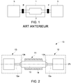
- the figure 1 illustrates an example of an industrial installation according to the prior art comprising a rotary electrical machine 1 comprising a rotor 2 with a through shaft or a monobloc rotor comprising a shaft and a magnetic body made of the same material, connected on the one hand to a turbine gas 3 by a coupling device 4 and, on the other hand, to a compressor 5 by a coupling device 6.
- the gas turbine produces and transmits to the rotor 2 a mechanical power of 130 MW and the electric machine 1 generates a power of electrical origin of 45 MW.
- the compressor 5 receives via the rotor 2 a total power of 175 MW resulting from the sum of the mechanical and electrical powers.
- the coupling device 6 is dimensioned to transmit a power of at least 175 MW.
- the torque transmitted via the coupling devices 4 and 6 is for example greater than a million Nm (Newtonmeter) at a low speed of rotation less than 200 revolutions per minute, or the transmitted torque is for example less than 200,000 Nm at a high speed of rotation greater than 3000 revolutions per minute.
- Nm Newtonmeter
- the document EP0609645 describes a laminated rotor comprising a non-through shaft for an asynchronous electric motor.
- the ends of the rotor are cylindrical and are each equipped with a coupling device.
- the document US9450470B2 describes a rotor comprising two magnetic masses not comprising an opening connected to each other by a half-shaft, each magnetic mass comprising at one free end a cylindrical non-traversing half-shaft.
- EP3048701 and EP3048703 disclose a rotor with a non-traversing shaft comprising two half-shafts.
- the end of one of the half-shafts comprises a coupling cake in one piece and the free end of the other half-shaft being cylindrical supporting the mass of the rotor via a bearing located at this same end.
- the cylindrical half-shaft has no coupling function.
- the coupling cake is fixed to another coupling cake in one piece arranged for example at the end of the compressor shaft 5 to transmit the required torque.
- an attached coupling cake is mounted at the cylindrical end of the half-shaft, for example a coupling sleeve comprising a coupling cake.
- the coupling cake is mounted on the shaft for example by shrinking, by keying or by hydraulic shrinking of the coupling cake on a conical end of the shaft.
- the coupling of the rotor first requires making the coupling sleeve comprising a coupling cake and then mounting the assembly obtained on the shaft.
- the shaft must be extended to accommodate a hooping interface comprising the cake.
- the torque transferred by the added coupling cake is limited to prevent it from coming off the shaft and turning on itself.
- the coupling cake has grooves cooperating with grooves located at the end of the shaft.
- each half-shaft comprises a single-piece coupling cake.
- the magnetic sheets include a central recess, and for high peripheral rotational speeds, for example of 300 m / s, mechanical stresses arise. concentrate around the recess and are likely to damage the magnetic sheets.
- a monobloc rotor comprising two shaft ends, a magnetic mass and coupling cakes connected to the shaft ends made of the same material.
- the invention proposes a rotor with a non-traversing shaft for an electrical machine comprising a cylindrical magnetic mass enclosed between two half-shafts each comprising a fixing flange connected to the magnetic mass.
- Each half-shaft is made in one piece and includes a coupling cake located opposite the fixing flange.
- the fixing flange and the coupling cake of a half-shaft are connected by a median shaft.
- the median trees have different lengths.
- the outside diameter of at least one coupling cake is less than or equal to the outside diameter of the magnetic mass.
- the half-shafts are identical.
- the coupling cake comprises through holes distributed over at least one diameter to accommodate fixing means so as to transmit a torque.
- the through holes are staggered over at least two different diameters of the cake.
- the through holes are alternately smooth and tapped.
- the magnetic mass comprises compacted magnetic sheets.
- the magnetic mass comprises a stack of metal plates.
- the rotor with a non-traversing shaft further comprises tie rods distributed uniformly over at least one diameter of the magnetic mass so as to keep the magnetic mass compacted between the half-shafts, the diameter of at least one median shaft. being greater than the installation diameter of the tie rods, the outside diameter of the fixing flange of said half-shaft being equal to the diameter of the median shaft, one end of each tie rod being engaged in a tapping of the median shaft comprising as much tapping than tie rods.
- the magnetic mass comprises a one-piece metal body.
- the magnetic mass comprises a central recess.
- the magnetic mass comprises conductive bars and two short-circuit crowns so as to form a squirrel cage, the short-circuit crowns not being compacted between the fixing flanges and the magnetic mass.
- an assembly of rotors is proposed in series comprising at least two rotors with non-traversing shaft as defined above, in which a coupling cake of a rotor is fixed to a coupling cake of the another rotor to transmit torque between the two rotors.
- the rotor coupling cakes are fixed to each other by means of an intermediate shaft comprising two coupling cakes.
- the intermediate shaft is supported by a bearing.
- a rotor with multiple magnetic masses comprising a rotor with a non-traversing shaft as defined above, and at least one cylindrical magnetic mass of which a first end is connected to the fixing flange of a third. integral half-shaft and the second end is connected to a rotor coupling cake to transmit a torque between the magnetic masses.
- a rotary electrical machine comprising a rotor with non-traversing shaft, an assembly of rotors in series or a rotor with multiple magnetic masses as defined above.
- FIG 2 illustrates a first embodiment of an industrial installation 10 comprising a rotary electrical machine 11, a first end of the rotor 15 of which is connected to a first mechanical system 12 and a second end of the rotor of which is connected to a second mechanical system 13.
- the rotary electrical machine 11 further comprises a stator 14 into which is inserted a rotor 15 comprising a shaft which does not pass through a central axis (A).
- the rotary electrical machine 11 can be a machine of the asynchronous type with wound rotor, asynchronous with squirrel cage or synchronous whose feeding of the rotor is done preferably by means of rings and brushes.
- the first and second mechanical systems 12 and 13 each comprise a shaft 12a and 13a each comprising a coupling cake 12b and 13b.
- the coupling cakes 12b and 13b are connected to respective ends of the rotor 15 to transmit mechanical torque between the rotor 15 and the mechanical systems 12 and 13.
- the first mechanical system 12 is for example a gas turbine and the second mechanical system 13 is for example a compressor consuming the torque supplied by the gas turbine.
- the second mechanical system 13 receives on its shaft 13a a torque equal to the sum of the torques generated by the machine 11 and the first mechanical system 12, the rotor 15 being dimensioned to transmit the torques generated by the machine and the gas turbine, for example a torque up to a million Nm
- the torque generated by the first mechanical system 12 is transmitted to the second mechanical system 13 via the rotor 15.
- FIG. 3 illustrates an axial sectional view of a first embodiment of the rotor 15 with a non-traversing shaft for an asynchronous rotating electrical machine with a squirrel cage.
- the rotor 15 with a non-traversing shaft comprises a cylindrical magnetic mass 16 enclosed by two half-shafts 17 and 18.
- the magnetic mass 16 has an outside diameter d16.
- the half-shafts 17 and 18 each comprise a fixing flange 17a and 18a connected to one end of the magnetic mass 16, and a coupling cake 17b and 18b situated opposite the fixing flange 17a and 18a and connected to the corresponding mechanical system 12 or 13.
- Each half-shaft 17 and 18 is made in one piece.
- the coupling cake 17b and 18b is not attached to the half-shaft 17 and 18.
- each coupling cake can transmit, by material continuity, a torque of higher value than in the case of a half-shaft comprising a coupling cake added and secured to the half-shaft, for example by shrinking or keying.
- the half-shafts 17 and 18 are obtained for example by forging or molding and are for example made of steel.
- Each half-shaft 17 and 18 further comprises a central shaft 17c and 18c between the fixing flange 17a or 18a and the coupling cake 17b or 18b.
- Each median shaft 17c and 18c can be supported in rotation by a bearing (not shown) or without bearing if each shaft 12a and 13a is supported by a bearing.
- the coupling cakes 17b and 18b are cylindrical and include an outside diameter d17 and d18 respectively.
- the outside diameter d17 and d18 of at least one coupling cake 17 and 18 is less than or equal to the outside diameter d16 of the magnetic mass 16 so that the rotor 15 can be inserted into the stator 14 of the electric machine 11 without disassembly of the stator or without insertion of the rotor 15 in a stator comprising several assembled and removable parts.
- the half-shafts 17 and 18 are identical.
- the rotor 15 is symmetrical with respect to a plane (P1) perpendicular to the axis of rotation (A) and passing through a plane of symmetry of the magnetic mass 16.
- the natural modes of the rotor 15 are not duplicated, the rotor 15 comprising fewer natural modes than in the case of different half-shafts making it possible to increase the range of rotational speeds usable in deteriorating the rotor 15.
- the rotary electrical machine 11 can be moved angularly by an angle of 180 ° for example to optimize the passage of cables connecting the stator to a supply device.
- the two oil cakes 17b and 18b are in the same place allowing coupling to the mechanical systems 12 and 13 when the machine 11 has been moved angularly by 180 °.
- the magnetic mass 16 comprises two short-circuit discs 19 enclosing compacted magnetic sheets 20 and conductive bars 21 housed in the magnetic sheets 20 and the short-circuit discs 19 so the short-circuit discs 19 and the conductive bars 21 form a squirrel cage.
- Rods 22 are distributed uniformly over a diameter of the magnetic mass 16 so as to keep the magnetic sheets 20 compacted between the half-shafts 17 and 18.
- the tie rods 22 pass through smooth holes arranged in the half-shafts 17 and 18, and comprise at each end a nut so as to keep the magnetic sheets 20 compacted.
- the diameter d17c of the median shaft 17c is chosen so that it is greater than the installation diameter of the tie rods 22 so that one end of each tie rod 22 is engaged in a tapping of the median shaft 17c, the central shaft 17c comprising as many threads distributed over a diameter of the central shaft as there are tie rods 22.
- the external diameter d17a of the fixing flange 17a is equal to the diameter d17c of the central shaft 17c.
- the magnetic mass 16 comprises compacted metal plates replacing the compacted magnetic sheets.
- the thickness of the magnetic sheets 20 is preferably less than 2 mm, preferably 0.65 mm, for example 0.5 mm.
- the thickness of the metal plates is preferably greater than 5% of the external diameter d16 of the magnetic mass 16.
- the metal plates are interconnected by screws embedded in the plates, and the metal plates located at the ends are connected to the half-shafts 17 and 18 by screws embedded in the end plates.
- Each coupling cake 17b and 18b includes through holes 23 and 24 distributed over a diameter to accommodate fixing means so as to transmit a torque.
- the through holes 23 and 24 are distributed uniformly over the diameter and / or each coupling cake 17b and 18b comprises an even number of through holes 23 and 24.
- Each coupling cake 17b and 18b preferably comprises between 6 and 48 through holes.
- the center of the through holes 23, 24 are distributed uniformly over the same diameter d23a, d24a less than or equal to 0.9 times the outside diameter d17, d18 of the coupling cake 17, 18.
- the through holes 23 and 24 preferably have a diameter d23 and d24 less than or equal to 0.1 times the outside diameter d17 and d18 of the corresponding coupling cake 17 and 18.
- the coupling cakes 17 and 18 preferably have a thickness e17 and e18 less than or equal to 0.2 times the outside diameter d17 and d18 of the corresponding coupling cake 17 and 18.
- Through holes 23 and 24 are smooth holes.
- the fixing means comprise bolts or threaded rods comprising at each of their ends a nut so that the coupling cakes of the half-shafts 17 and 18 are integral with the coupling cakes of the mechanical systems 12 and 13 for transmission of couple.
- these comprise tapped holes and the through holes of the cake of the mechanical systems are smooth. Screws passing through the smooth holes cooperate with the threads so as to transmit a torque between the rotor 15 and the mechanical systems 12 and 13.
- the coupling cake 17b comprises alternately smooth through holes 23 and tapped 26
- the coupling cake 13b of the second mechanical system 13 comprises alternately smooth through holes 27 and tapped 28 arranged so that a smooth hole 25 of the cake 17b is coaxial with a tapped hole 28 of the cake 13b, and that a tapped hole 26 of the cake 17b is coaxial with a smooth hole 27 of the cake 13b.
- Screws 29 each pass through a smooth hole 27, 25 of a cake 13b, 17b and each screw is engaged in a tapped hole 26, 28 of a cake 17b, 13b.
- the coupling cake 18b can comprise through holes 24 according to the third embodiment cooperating with the coupling cake 12b of the first mechanical system 12.
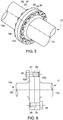
- the figure 5 illustrates a partial view of the half-shaft 17 comprising the coupling cake 17b and the central shaft 17c, the shaft 13a comprising the coupling cake 13b and the screws 29, and the figure 6 illustrates a partial section along an axial direction of the figure 5 .
- the heads of the screws 29 are arranged alternately on the side of the median shaft 17c and of the shaft 13a making it possible to reduce the angular distance separating two adjacent through holes so as to increase the number of screws 29 to increase the maximum torque transmitted through the coupling cakes 13b and 17b.
- the two coupling cakes can have through holes of different types or of the same type, the two cakes 17b and 18b coupling being designed to cooperate with the coupling cake 13b and 12b of the mechanical systems 13 and 12, or vice versa if the rotor 15 is symmetrical and angularly displaced by an angle of 180 °.
- the coupling cake 17b can have smooth holes and the coupling cake 18b can have tapped holes or smooth and tapped holes, as described above.
- the centers of the through holes 23, 24 of the coupling cake 17b, 18b are distributed in a staggered fashion over two diameters D1 and D2 different from the coupling cake 17b, 18b, the diameter D2 being greater than the diameter D1, the through holes 23 , 24 being preferably arranged in an even number on each of the diameters D1 and D2.
- the diameter D2 is less than or equal to 0.9 times the outside diameter d17, d18 of the coupling cake 17b, 18b, and the diameter D1 of the second row of through holes 23, 24 is preferably less than or equal to 0.8 times the outside diameter d17, d18 of the coupling cake 17b, 18b.
- each through hole d23, d24 is preferably less than or equal to 0.1 times the outside diameter d17, d18 of the coupling cake 17b, 18b.
- the through holes 23, 24 can be distributed over at least three different diameters of the coupling cake 17b, 18b, to transmit more torque.
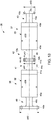
- the figure 8 illustrates a view of a third embodiment of the rotor 15 with a non-traversing shaft.
- This embodiment differs from the first embodiment of the rotor 15 in that the outside diameter d18 of the coupling cake 18b is less than the outside diameter d17 of the coupling cake 17b, the outside diameter d17 of the coupling cake 17b being greater than the outside diameter d16 of the magnetic mass 16.
- the outside diameter d18 of the coupling cake 18b is smaller than the outside diameter d16 of the magnetic mass 16 so as to insert the rotor 15 into the stator 14 without removing the stator.
- the figure 9 illustrates a view of a fourth embodiment of the rotor 15 with a non-traversing shaft.
- This embodiment differs from the first embodiment of the rotor 15 in that the central shafts 17c and 18c respectively connecting the fixing flanges 17a and 18a and the coupling cakes 17b and 18b are of different length L17 and L18.
- the figure 10 illustrates a partial section along an axial direction of a fifth embodiment of the rotor 15.
- magnetic mass 16 comprises a one-piece metal body 30 and the fixing flanges 17a and 18a also include counterbore 31.
- the rotor 15 also comprises screws 32 distributed uniformly over a diameter of each half-shaft 17 and 18.
- Each screw 32 is engaged in a tapping 33 of the one-piece metal body 30 so as to keep the short-circuit disks 19 and the metal body 30 compacted between the half-shafts 17 and 18.
- Each screw head 32a is housed in a counterbore 31 of the half-shaft 17 and 18.
- the fixing flanges 17a and 18a do not include counterbore.
- the one-piece metal body 30 further comprises housings 34 receiving the conductive bars 21 uniformly distributed over a diameter of the one-piece metal body 30 forming with the short-circuit discs 19 a squirrel cage.
- the magnetic sheets 20 and the short-circuit discs 19 comprise a central recess so that the magnetic mass 16 comprises a central recess 34.
- This embodiment of the magnetic mass 16 is permitted when the peripheral speed of the rotor 15 is less than 180 m / s so that the concentration of mechanical stresses generated during the rotation of the rotor 15 on the periphery of the central recess 34 of each of the magnetic sheets 20 is not likely to deteriorate the magnetic mass 16.
- the central recess 34 of the magnetic mass 16 makes it possible to lighten the rotor mass so as to increase the critical speed of the rotor 15.
- the central recess does not have a through shaft or a central tie-rod ensuring the compaction of the magnetic mass 16.
- the short-circuit discs 19 are preferably made of copper or alloyed copper.
- the short-circuit discs 19 generally have a lower elastic limit than that of the magnetic sheets 20.
- the short-circuit discs 19 do not include a central recess.
- a seventh embodiment of the rotor 15 is illustrated in the figure 12 and differs from the sixth embodiment illustrated in figure 11 in that the magnetic mass 16 does not include a short-circuit disc 19.
- the rotor 15 comprises short-circuit rings 19a which are not compacted between the fixing flanges 17a and 18a and the magnetic mass 16.
- the short-circuit crowns referenced 19a and the conductive bars 21 form a squirrel cage.
- the magnetic mass 16 does not include a central recess.
- the invention also applies to a rotor with a wound asynchronous non-traversing shaft.
- the busbars are replaced by notches housing coils connected together.
- the invention also applies to a rotor with a wound synchronous non-traversing shaft preferably supplied by a ring and brush device.
- the bus bars can then be replaced by notches housing coils connected for example to the rings.
- FIG 13 illustrates a first embodiment of an assembly of rotors in series 35 comprising two rotors 36 and 37 comprising a non-through shaft similar to the rotor 15.
- the first and second rotors 36 and 37 each comprise a magnetic mass 38 and 39 sandwiched between two half-shafts 40, 41 and 42, 43, each half-shaft being in one piece and similar to the half-shafts described above.
- the magnetic masses 38 and 39 are identical, for example of the monobloc type and of the same dimensions.
- the first half-shaft 40 of the first rotor 36 comprises a fixing flange 40a connected to the magnetic mass 38 and a coupling cake 40b connected by a median shaft 40c to the fixing flange, the outside diameter d40 of the coupling cake 40b being greater than the outside diameter d38 and d39 of the magnetic masses 38 and 39 of the first and second rotors 36 and 37.
- the second half-shaft 41 of the first rotor 36 comprises a fixing flange 41a connected to the magnetic mass 38 and a coupling cake 41b connected by a median shaft 41c to the fixing flange, the outside diameter d41 of the coupling cake 41b being less than the outside diameter d38 and d39 of the magnetic masses 38 and 39 of the first and second rotors 36 and 37.
- the first half-shaft 42 of the first rotor 37 comprises a fixing flange 42a connected to the magnetic mass 39 and a coupling cake 42b connected by a median shaft 42c to the fixing flange, the outside diameter d42 of the coupling cake 42b being less than the outside diameter d38 and d39 of the magnetic masses 38 and 39 of the first and second rotors 36 and 37.
- the coupling cakes 41b and 42b of the second half-shaft 41 of the first rotor 36 and of the first half-shaft 42 of the second rotor 37 are dimensioned to be secured, for example by bolts passing through the coaxial through holes 44 and 45 of the coupling cakes 41b and 42b for transmitting a torque between the two rotors 36 and 37.
- the second half-shaft 43 of the first rotor 37 comprises a fixing flange 43a connected to the magnetic mass 39 and a coupling cake 43b connected by a median shaft 43c to the fixing flange, the outside diameter d43 of the coupling cake 43b being less than the outside diameter d38 and d39 of the magnetic masses 38 and 39 of the first and second rotors 36 and 37.
- the outside diameters of the coupling cakes d40, d41, d42, and d43 are chosen so that the assembly of rotors in series 35 can be inserted into a stator 14 comprising two sub-stators each cooperating with a rotor 36 and 37 without disassembly of the stator 14 and so that each rotor 36 and 37 generates an electromagnetic torque.
- the diameters referenced d41, d42 and d43 are less than the diameters referenced d38 and d39, and the diameter referenced d40 is greater than the diameters referenced d38 and d39.
- the diameters referenced d40, d41 and d42 are less than the diameters referenced d38 and d39, and the diameter referenced d43 is greater than the diameters referenced d38 and d39.
- the direction of insertion of the series rotor assembly 35 in the stator is reversed compared to the previous example.
- the diameters referenced d40, d41, d42 and d43 are smaller than the diameters referenced d38 and d39 allowing insertion of the rotor assembly in series 35 in the stator in both directions.
- the magnetic masses 36 and 37 can be of different dimensions and / or types comprising for example magnetic sheets 20 or a stack of metal plates.
- the series rotor assembly 35 may further comprise an intermediate shaft 46 disposed between the coupling cakes 41b and 42b of the second half-shaft 41 of the first rotor 36 and of the first half-shaft 42 of the second rotor 37 so as to transmit a torque between the two rotors 36 and 37 as illustrated in the figure 14 .
- the intermediate shaft 46 comprises at each of its ends a coupling cake 47 and 48 cooperating with the coupling cake 41b and 42b of the rotors 36 and 37.
- the coupling cakes 47 and 48 of the intermediate shaft 46 each include through holes 47a and 48a cooperating with the through holes 44 and 45 of the coupling cakes 41b and 42b to accommodate, for example, bolts.
- the intermediate shaft 46 makes it possible to separate the rotors 36 and 37 from one another so as to create a space simplifying the maintenance of the rotary electric machine 11.
- the critical speed can be modified by adjusting the geometrical characteristics or the material of the intermediate shaft 46, it suffices to produce two identical rotors 36 and 37 and to connect them with an intermediate shaft dimensioned to adjust the critical speed of the assembly 35 at the desired critical speed.
- the intermediate shaft can be supported in rotation by a bearing 49.
- the support of the intermediate shaft 46 by the bearing 49 makes it possible to increase the critical speed in bending of the assembly 35 of rotors in series.
- the assembly 35 of rotors in series may comprise more than two rotors in series, certain adjacent rotors being connected by an intermediate shaft supported or not by a bearing, the stator comprising as many sub-stators as there are rotors and each cooperating with a rotor so as to generate an electromagnetic torque.
- FIG 15 illustrates an exemplary embodiment of a rotor with multiple magnetic masses 50.
- the rotor with multiple magnetic masses 50 comprises a rotor 37 as described above and a second cylindrical magnetic mass 51, the ends of which are connected on the one hand to the coupling cake 42b of the first half-shaft 42 of the rotor 37 and, on the other hand, to the fixing flange 52a of a third half-shaft 52 similar to the half-shafts 42 and 43.
- the magnetic masses 39 and 51 are identical, but they can be of different types and / or of different dimensions.
- the outside diameter of the magnetic masses 39 and 51, and the outside diameter of the half-shafts 42, 43 and 52 are dimensioned so that the rotor 50 can be inserted into the stator 14 which comprises as many sub-stators as there are magnetic masses of so as to generate an electromagnetic torque.
- the rotor with multiple magnetic masses 50 comprises a support bearing for supporting the median shaft 42c in rotation.
- the support bearing makes it possible to increase the critical speed in bending of the rotor with multiple magnetic masses 50.
- the rotor with multiple magnetic masses can comprise more than two magnetic masses, the magnetic masses being separated by half-shafts supported or not by bearings.
- the rotary electrical machine comprising the series assembly of rotors or the rotor with multiple magnetic masses makes it possible to develop an electrical power greater than that of a machine comprising a single rotor while respecting the maximum dimensioning values of the rotary electrical machines, for example by not exceeding a peripheral speed of the rotor of 300 m / s and by mastering the dimensional characteristics of the rotary electric machine so that it is for example transportable and easily dismountable for easier maintenance.
- the rotary electrical machine comprising the rotor 15, the series assembly of rotors 35 or the rotor with multiple magnetic masses 50 can operate in motor or generator mode.
- the outside diameter of the coupling cakes of an element comprising the rotor 15, the series assembly of rotors 35 or the rotor with multiple magnetic masses 50 is greater than the diameter of their magnetic mass.
- the stator housing one of these elements comprises several parts assembled around the element so that the element is disposed in the stator without being dismantled, the stator and the element forming a rotating electric machine.
- the rotor 15, the series assembly of rotors 35 and the rotor with multiple magnetic masses 50 make it possible to transfer a torque up to a million N.m.
Landscapes
- Engineering & Computer Science (AREA)
- Power Engineering (AREA)
- Iron Core Of Rotating Electric Machines (AREA)
Abstract
Description
- La présente invention concerne les machines électriques tournantes et se rapporte plus particulièrement à un rotor de machine électrique comprenant un arbre non traversant.
- La présente invention concerne également un assemblage de plusieurs rotors, un rotor à masses magnétiques multiples et une machine électrique tournante comprenant un tel assemblage de rotors ou un tel rotor.
- La
figure 1 illustre un exemple d'installation industrielle selon l'art antérieur comprenant une machine électrique tournante 1 comprenant un rotor 2 avec un arbre traversant ou un rotor monobloc comprenant un arbre et un corps magnétique venus de même matière, relié d'une part à une turbine à gaz 3 par un dispositif d'accouplement 4 et, d'autre part, à un compresseur 5 par un dispositif d'accouplement 6. - Par exemple, la turbine à gaz produit et transmet au rotor 2 une puissance mécanique de 130 MW et la machine électrique 1 génère une puissance d'origine électrique de 45 MW.
- Le compresseur 5 reçoit par l'intermédiaire du rotor 2 une puissance totale de 175 MW résultant de la somme des puissances mécanique et d'origine électrique.
- Par conséquent, le dispositif d'accouplement 6 est dimensionné pour transmettre une puissance d'au moins 175 MW.
- Selon les modes d'utilisation de l'installation industrielle, le couple transmis par l'intermédiaire des dispositifs d'accouplement 4 et 6 est par exemple supérieur à un million de N.m (Newton.mètre) à une basse vitesse de rotation inférieure à 200 tours par minute, ou le couple transmis est par exemple inférieur à 200000 N.m à une haute vitesse de rotation supérieure à 3000 tours par minute.
- Le document
EP0609645 décrit un rotor feuilleté comprenant un arbre non traversant pour un moteur électrique asynchrone. - Les extrémités du rotor sont cylindriques et sont chacune équipées d'un dispositif d'accouplement.
- Le document
US9450470B2 -
- L'extrémité de l'un des demi-arbres comprend un tourteau d'accouplement d'un seul tenant et l'extrémité libre de l'autre demi-arbre étant cylindrique supportant la masse du rotor via un palier situé à cette même extrémité.
- Le demi-arbre cylindrique n'a pas de fonction d'accouplement.
- Le tourteau d'accouplement est fixé à un autre tourteau d'accouplement d'un seul tenant disposé par exemple à l'extrémité de l'arbre du compresseur 5 pour transmettre le couple requis.
- Il est donc également nécessaire de rapporter un dispositif d'accouplement à l'extrémité du deuxième arbre pour transmettre un couple à cette extrémité.
- Généralement, un tourteau d'accouplement rapporté est monté à l'extrémité cylindrique du demi-arbre, par exemple un manchon d'accouplement comprenant un tourteau d'accouplement.
- Le tourteau d'accouplement est monté sur l'arbre par exemple par frettage, par clavetage ou par frettage hydraulique du tourteau d'accouplement sur une extrémité conique de l'arbre.
- L'accouplement du rotor nécessite d'abord de réaliser le manchon d'accouplement comprenant un tourteau d'accouplement puis de monter l'ensemble obtenu sur l'arbre.
- Les opérations de production du tourteau et de montage sur l'arbre nécessitent des phases d'usinage spécifiques du tourteau et de l'arbre.
- Ces opérations nécessitent des tolérances de fabrication fines coûteuses sur le tourteau d'accouplement rapporté et sur l'extrémité de l'arbre recevant le tourteau d'accouplement.
- En outre, l'arbre doit être allongé pour accueillir une interface de frettage comprenant le tourteau.
- Comme il s'agit d'une pièce rapportée, le couple transféré par le tourteau d'accouplement rapporté est limité pour empêcher qu'il ne se désolidarise de l'arbre et ne tourne sur lui-même.
- Pour augmenter la valeur du couple transmissible par le tourteau d'accouplement rapporté, le tourteau d'accouplement comporte des cannelures coopérant avec des cannelures situées à l'extrémité de l'arbre.
- Cependant, la réalisation de l'arbre cannelé et du tourteau d'accouplement associé entraîne des opérations d'usinage complexes supplémentaires longues et coûteuses.
- On connaît du document
US9190879 - L'extrémité libre de chaque demi-arbre comprend un tourteau d'accouplement d'un seul tenant.
- Cependant, comme les tôles magnétiques comprennent un évidement central, et pour des vitesses de rotation périphérique élevées, par exemple de 300 m/s, des contraintes mécaniques se concentrent autour de l'évidement et sont susceptibles d'endommager les tôles magnétiques.
- On connaît également de l'état de la technique un rotor monobloc comprenant deux extrémités d'arbre, une masse magnétique et des tourteaux d'accouplement reliés aux extrémités d'arbre venus de même matière.
- Cependant un tel rotor n'est pas démontable, la masse magnétique et l'arbre étant massifs et monoblocs.
- Par conséquent, les rotors de grandes tailles sont difficilement transportables.
- De plus, si un élément du rotor, par exemple une extrémité de l'arbre casse, il n'est pas possible de réparer le rotor.
- Il est donc proposé de pallier les inconvénients des rotors comprenant un arbre non traversant selon l'état de la technique, notamment en augmentant la valeur du couple transmissible à travers le rotor tout en limitant le nombre d'éléments du rotor pour limiter la complexité de réalisation du rotor, l'encombrement du rotor et en facilitant son démontage.
- Au vu de ce qui précède l'invention propose un rotor à arbre non traversant pour machine électrique comprenant une masse magnétique cylindrique enserrée entre deux demi-arbres comprenant chacun une bride de fixation reliée à la masse magnétique.
- Chaque demi-arbre est réalisé d'un seul tenant et comprend un tourteau d'accouplement situé à l'opposé de la bride de fixation.
- Selon une caractéristique, la bride de fixation et le tourteau d'accouplement d'un demi-arbre sont reliés par un arbre médian.
- Avantageusement, les arbres médians ont des longueurs différentes.
- De préférence, le diamètre extérieur d'au moins un tourteau d'accouplement est inférieur ou égal au diamètre extérieur de la masse magnétique.
- De préférence, les demi-arbres sont identiques.
- Avantageusement, le tourteau d'accouplement comprend des trous débouchants répartis sur au moins un diamètre pour accueillir des moyens de fixation de manière à transmettre un couple.
- Selon une autre caractéristique, les trous débouchants sont répartis en quinconce sur au moins deux diamètres différents du tourteau.
- De préférence, les trous débouchants sont alternativement lisses et taraudés.
- Avantageusement, la masse magnétique comprend des tôles magnétiques compactées.
- De préférence, la masse magnétique comprend un empilement de plaques métalliques.
- Selon une autre caractéristique, le rotor à arbre non traversant comprend en outre des tirants répartis uniformément sur au moins un diamètre de la masse magnétique de manière à maintenir la masse magnétique compactée entre les demi-arbres, le diamètre d'au moins un arbre médian étant supérieur au diamètre d'implantation des tirants, le diamètre extérieur de la bride de fixation dudit demi-arbre étant égal au diamètre de l'arbre médian, une extrémité de chaque tirant étant en prise dans un taraudage de l'arbre médian comprenant autant de taraudages que de tirants.
- De préférence, la masse magnétique comprend un corps métallique monobloc.
- Avantageusement, la masse magnétique comprend un évidement central.
- De préférence, la masse magnétique comprend des barres conductrices et deux couronnes de court-circuit de manière à former une cage d'écureuil, les couronnes de court-circuit n'étant pas compactées entre les brides de fixation et la masse magnétique.
- Selon un autre aspect, il est proposé un assemblage de rotors en série comprenant au moins deux rotors à arbre non traversant tels que définis précédemment, dans lequel un tourteau d'accouplement d'un rotor est fixé à un tourteau d'accouplement de l'autre rotor pour transmettre un couple entre les deux rotors.
- De préférence, les tourteaux d'accouplement des rotors sont fixés entre eux par l'intermédiaire d'un arbre intermédiaire comprenant deux tourteaux d'accouplement.
- Avantageusement, l'arbre intermédiaire est soutenu par un palier.
- Selon encore un autre aspect, il est proposé un rotor à masses magnétiques multiples, comprenant un rotor à arbre non traversant tel que défini précédemment, et au moins une masse magnétique cylindrique dont une première extrémité est reliée à la bride de fixation d'un troisième demi-arbre d'un seul tenant et la deuxième extrémité est reliée à un tourteau d'accouplement du rotor pour transmettre un couple entre les masses magnétiques.
- Selon encore un autre aspect, il est proposé une machine électrique tournante comprenant un rotor à arbre non traversant, un assemblage de rotors en série ou un rotor à masses magnétiques multiples tel que défini précédemment.
- D'autres caractéristiques et avantages de l'invention apparaîtront à la lecture de la description qui suit de modes de réalisation de l'invention, donnés uniquement à titre d'exemples non limitatifs et en référence aux dessins sur lesquels :
- la
figure 1 , dont il a déjà été fait mention, illustre une installation industrielle comprenant une machine électrique tournante selon l'état de la technique ; - la
figure 2 illustre un premier mode de réalisation d'une installation industrielle ; - la
figure 3 illustre un premier mode de réalisation d'un rotor à arbre non traversant ; - la
figure 4 illustre un deuxième mode de réalisation d'un rotor à arbre non traversant ; - les
figures 5 et 6 illustrent un troisième mode de réalisation du tourteau d'accouplement ; - la
figure 7 illustre un quatrième mode de réalisation du tourteau d'accouplement ; - la
figure 8 illustre un troisième mode de réalisation du rotor à arbre non traversant ; - la
figure 9 illustre un quatrième mode de réalisation du rotor à arbre non traversant ; - la
figure 10 illustre un cinquième mode de réalisation du rotor à arbre non traversant ; - la
figure 11 illustre un sixième mode de réalisation du rotor à arbre non traversant ; - la
figure 12 illustre un septième mode de réalisation du rotor à arbre non traversant ; - la
figure 13 illustre un premier mode de réalisation d'un assemblage de rotors en série ; - la
figure 14 illustre un deuxième mode de réalisation d'un assemblage de rotors en série ; et - la
figure 15 illustre un exemple de mode de réalisation d'un rotor à masses magnétiques multiples. - On se réfère à la
figure 2 qui illustre un premier mode de réalisation d'une installation industrielle 10 comprenant une machine électrique tournante 11 dont une première extrémité du rotor 15 est reliée à un premier système mécanique 12 et une deuxième extrémité du rotor est reliée à un deuxième système mécanique 13. - La machine électrique tournante 11 comprend en outre un stator 14 dans lequel est inséré un rotor 15 comprenant un arbre non traversant d'un axe central (A).
- La machine électrique tournante 11 peut être une machine du type asynchrone à rotor bobiné, asynchrone à cage d'écureuil ou synchrone dont l'alimentation du rotor se fait de préférence par l'intermédiaire de bagues et balais.
- Les premier et deuxième systèmes mécaniques 12 et 13 comprennent chacun un arbre 12a et 13a comprenant chacun un tourteau d'accouplement 12b et 13b.
- Les tourteaux d'accouplement 12b et 13b sont reliés à des extrémités respectives du rotor 15 pour transmettre un couple mécanique entre le rotor 15 et les systèmes mécaniques 12 et 13.
- Le premier système mécanique 12 est par exemple une turbine à gaz et le deuxième système mécanique 13 est par exemple un compresseur consommant le couple fourni par la turbine à gaz.
- Si la machine électrique tournante 11 fonctionne en mode moteur, le deuxième système mécanique 13 reçoit sur son arbre 13a un couple égal à la somme des couples générés par la machine 11 et le premier système mécanique 12, le rotor 15 étant dimensionné pour transmettre les couples générés par la machine et la turbine à gaz, par exemple un couple jusqu'à un million de N.m.
- Si la machine électrique tournante 11 fonctionne en mode générateur, le couple généré par le premier système mécanique 12 est transmis au deuxième système mécanique 13 par l'intermédiaire du rotor 15.
- On se référera à la
figure 3 qui illustre une vue en coupe axiale d'un premier mode de réalisation du rotor 15 à arbre non traversant pour machine électrique tournante asynchrone à cage d'écureuil. - Le rotor 15 à arbre non traversant comprend une masse magnétique cylindrique 16 enserrée par deux demi-arbres 17 et 18.
- La masse magnétique 16 a un diamètre extérieur d16.
- Les demi-arbres 17 et 18 comprennent chacun une bride de fixation 17a et 18a reliée à une extrémité de la masse magnétique 16, et un tourteau d'accouplement 17b et 18b situé à l'opposé de la bride de fixation 17a et 18a et relié au système mécanique 12 ou 13 correspondant.
- Chaque demi-arbre 17 et 18 est réalisé d'un seul tenant. Le tourteau d'accouplement 17b et 18b n'est pas rapporté sur le demi-arbre 17 et 18.
- Par conséquent, chaque tourteau d'accouplement peut transmettre par continuité de matière un couple de valeur plus élevée que dans le cas d'un demi-arbre comprenant un tourteau d'accouplement rapporté et solidarisé au demi-arbre par exemple par frettage ou clavetage.
- Les demi-arbres 17 et 18 sont obtenus par exemple par forgeage ou moulage et sont par exemple réalisés en acier.
- Chaque demi-arbre 17 et 18 comprend en outre un arbre médian 17c et 18c entre la bride de fixation 17a ou 18a et le tourteau d'accouplement 17b ou 18b.
- Chaque arbre médian 17c et 18c peut être soutenu en rotation par un palier (non représenté) ou sans palier si chaque arbre 12a et 13a est supporté par un palier.
- Les tourteaux d'accouplement 17b et 18b sont cylindriques et comprennent respectivement un diamètre extérieur d17 et d18.
- Le diamètre extérieur d17 et d18 d'au moins un tourteau d'accouplement 17 et 18 est inférieur ou égal au diamètre extérieur d16 de la masse magnétique 16 de sorte que le rotor 15 peut être inséré dans le stator 14 de la machine électrique 11 sans démontage du stator ou sans insertion du rotor 15 dans un stator comprenant plusieurs parties assemblées et démontables.
- Les demi-arbres 17 et 18 sont identiques.
- Par conséquent, le rotor 15 est symétrique par rapport à un plan (P1) perpendiculaire à l'axe de rotation (A) et passant par un plan de symétrie de la masse magnétique 16.
- Les modes propres du rotor 15 ne sont pas dédoublés, le rotor 15 comportant moins de modes propres que dans le cas de demi-arbres différents permettant d'augmenter la plage des vitesses de rotation utilisables dans détériorer le rotor 15.
- De plus, la machine électrique tournante 11 peut être déplacée angulairement d'un angle de 180° par exemple pour optimiser le passage de câbles reliant le stator à un dispositif d'alimentation. Comme le rotor 15 est symétrique, les deux tourteaux 17b et 18b sont au même endroit permettant un accouplement aux systèmes mécaniques 12 et 13 lorsque la machine 11 a été déplacée angulairement de 180°.
- Par ailleurs, la masse magnétique 16 comprend deux disques de court-circuit 19 enserrant des tôles magnétiques compactées 20 et des barres conductrices 21 logées dans les tôles magnétiques 20 et les disques de court-circuit 19 de sorte les disques de court-circuit 19 et les barres conductrices 21 forment une cage d'écureuil.
- Des tirants 22 sont répartis uniformément sur un diamètre de la masse magnétique 16 de manière à maintenir les tôles magnétiques 20 compactées entre les demi-arbres 17 et 18.
- Les tirants 22 passent à travers des trous lisses disposés dans les demi-arbres 17 et 18, et comprennent à chaque extrémité un écrou de manière à maintenir les tôles magnétiques 20 compactées.
- Selon un deuxième mode de réalisation du rotor 15 représenté à la
figure 4 , le diamètre d17c de l'arbre médian 17c est choisi de sorte qu'il soit supérieur au diamètre d'implantation des tirants 22 de sorte qu'une extrémité de chaque tirant 22 soit en prise dans un taraudage de l'arbre médian 17c, l'arbre médian 17c comprenant autant de taraudages répartis sur un diamètre de l'arbre médian que de tirants 22. Le diamètre extérieur d17a de la bride de fixation 17a est égal au diamètre d17c de l'arbre médian 17c. - En variante, la masse magnétique 16 comprend des plaques métalliques compactées remplaçant les tôles magnétiques compactées.
- L'épaisseur des tôles magnétiques 20 est de préférence inférieure à 2 mm, préférentiellement 0.65 mm, par exemple 0.5 mm.
- L'épaisseur des plaques métalliques est de préférence supérieure à 5% du diamètre extérieur d16 de la masse magnétique 16.
- Selon une autre variante, les plaques métalliques sont reliées entre elles par des vis noyées dans les plaques, et les plaques métalliques situées aux extrémités sont reliées aux demi-arbres 17 et 18 par des vis noyées dans les plaques d'extrémité.
- Chaque tourteau d'accouplement 17b et 18b comprend des trous débouchants 23 et 24 répartis sur un diamètre pour accueillir des moyens de fixation de manière à transmettre un couple.
- De préférence, les trous débouchants 23 et 24 sont répartis uniformément sur le diamètre et/ou chaque tourteau d'accouplement 17b et 18b comprend un nombre pair de trous débouchants 23 et 24.
- Chaque tourteau d'accouplement 17b et 18b comprend de préférence entre 6 et 48 trous débouchants.
- Le centre des trous débouchants 23, 24 sont répartis uniformément sur un même diamètre d23a, d24a inférieur ou égal à 0.9 fois le diamètre extérieur d17, d18 du tourteau d'accouplement 17, 18.
- Les trous débouchants 23 et 24 ont de préférence un diamètre d23 et d24 inférieur ou égal à 0.1 fois le diamètre extérieur d17 et d18 du tourteau d'accouplement 17 et 18 correspondant.
- Les tourteaux d'accouplement 17 et 18 ont de préférence une épaisseur e17 et e18 inférieure ou égale à 0.2 fois le diamètre extérieur d17 et d18 du tourteau d'accouplement 17 et 18 correspondant.
- Les trous débouchants 23 et 24 sont des trous lisses.
- Les moyens de fixation comprennent des boulons ou des tiges filetées comprenant à chacune de leurs extrémités un écrou de sorte que les tourteaux d'accouplement des demi-arbres 17 et 18 soient solidarisés aux tourteaux d'accouplement des systèmes mécaniques 12 et 13 de transmission de couple.
- Selon un deuxième mode de réalisation des trous débouchants 23 et 24, ceux-ci comprennent des trous taraudés et les trous débouchants des tourteaux des systèmes mécaniques sont lisses. Des vis passant par les trous lisses coopèrent avec les taraudages de manière à transmettre un couple entre le rotor 15 et les systèmes mécaniques 12 et 13.
- Selon un troisième mode de réalisation des trous débouchants 23 représenté aux
figures 5 et 6 , le tourteau d'accouplement 17b comprend des trous débouchants 23 alternativement lisses 25 et taraudés 26, et le tourteau d'accouplement 13b du deuxième système mécanique 13 comprend des trous débouchants alternativement lisses 27 et taraudés 28 disposés de sorte qu'un trou lisse 25 du tourteau 17b soit coaxial à un trou taraudé 28 du tourteau 13b, et qu'un trou taraudé 26 du tourteau 17b soit coaxial à un trou lisse 27 du tourteau 13b. - Des vis 29 passent chacune par un trou lisse 27, 25 d'un tourteau 13b, 17b et chaque vis est en prise dans un trou taraudé 26, 28 d'un tourteau 17b, 13b.
- Bien entendu, le tourteau d'accouplement 18b peut comprendre des trous débouchants 24 selon le troisième mode de réalisation coopérant avec le tourteau d'accouplement 12b du premier système mécanique 12.
- La
figure 5 illustre une vue partielle du demi-arbre 17 comprenant le tourteau d'accouplement 17b et l'arbre médian 17c, l'arbre 13a comprenant le tourteau d'accouplement 13b et les vis 29, et lafigure 6 illustre une coupe partielle selon une direction axiale de lafigure 5 . - Les têtes des vis 29 sont disposées alternativement du coté de l'arbre médian 17c et de l'arbre 13a permettant de réduire la distance angulaire séparant deux trous débouchants adjacents de manière à augmenter le nombre de vis 29 pour augmenter le couple maximal transmis à travers les tourteaux d'accouplement 13b et 17b.
- Selon d'autres modes de réalisation, les deux tourteaux d'accouplement peuvent comporter des trous débouchants de différents types ou de même type, les deux tourteaux d'accouplement 17b et 18b étant conçus de manière à coopérer avec les tourteaux d'accouplement 13b et 12b des systèmes mécaniques 13 et 12, ou inversement si le rotor 15 est symétrique et déplacé angulairement d'un angle de 180°.
- Par exemple le tourteau d'accouplement 17b peut comporter des trous lisses et le tourteau d'accouplement 18b peut comporter des trous taraudés ou des trous lisses et taraudés, tel que décrit précédemment.
- Selon un quatrième mode de réalisation du tourteau d'accouplement 17b, 18b illustré à la
figure 7 , les centres des trous débouchants 23, 24 du tourteau d'accouplement 17b, 18b sont répartis uniformément en quinconce sur deux diamètres D1 et D2 différents du tourteau d'accouplementl7b, 18b, le diamètre D2 étant supérieur au diamètre D1, les trous débouchants 23, 24 étant disposés de préférence en nombre pair sur chacun des diamètres D1 et D2. - De préférence, le diamètre D2 est inférieur ou égal à 0.9 fois le diamètre extérieur d17, d18 du tourteau d'accouplement 17b, 18b, et le diamètre D1 de la deuxième rangée de trous débouchants 23, 24 est de préférence inférieur ou égal à 0.8 fois le diamètre extérieur d17, d18 du tourteau d'accouplement 17b, 18b.
- Le diamètre de chaque trou débouchant d23, d24 est de préférence inférieur ou égal à 0.1 fois le diamètre extérieur d17, d18 du tourteau d'accouplement 17b, 18b.
- Bien entendu, les trous débouchants 23, 24 peuvent être répartis sur au moins trois diamètres différents du tourteau d'accouplement 17b, 18b, pour transmettre plus de couple.
- Les modes de réalisation des trous débouchants des tourteaux d'accouplement 17b et 18b décrits précédemment peuvent bien entendu être combinés.
- La
figure 8 illustre une vue d'un troisième mode de réalisation du rotor 15 à arbre non traversant. - On retrouve la masse magnétique 16 enserrée par les demi-arbres 17 et 18.
- Ce mode de réalisation diffère du premier mode de réalisation du rotor 15 en ce que le diamètre extérieur d18 du tourteau d'accouplement 18b est inférieur au diamètre extérieur d17 du tourteau d'accouplement 17b, le diamètre extérieur d17 du tourteau d'accouplement 17b étant supérieur au diamètre extérieur d16 de la masse magnétique 16.
- Le diamètre extérieur d18 du tourteau d'accouplement 18b est inférieur au diamètre extérieur d16 de la masse magnétique 16 de manière à insérer le rotor 15 dans le stator 14 sans démontage du stator.
- La
figure 9 illustre une vue d'un quatrième mode de réalisation du rotor 15 à arbre non traversant. - On retrouve la masse magnétique 16 enserrée par les demi-arbres 17 et 18.
- Ce mode de réalisation diffère du premier mode de réalisation du rotor 15 en ce que les arbres médians 17c et 18c reliant respectivement les brides de fixation 17a et 18a et les tourteaux d'accouplement 17b et 18b sont de longueur L17 et L18 différentes.
- Bien entendu, les deuxième et troisième modes de réalisation du rotor 15 peuvent être combinés.
- La
figure 10 illustre une coupe partielle selon une direction axiale d'un cinquième mode de réalisation du rotor 15. - Ce mode de réalisation différent du premier mode de réalisation illustré à la
figure 3 en ce que la masse magnétique 16 comprend un corps métallique monobloc 30 et les brides de fixation 17a et 18a comprennent en outre des lamages 31. - Le rotor 15 comporte en outre des vis 32 réparties uniformément sur un diamètre de chaque demi-arbre 17 et 18.
- Chaque vis 32 est en prise dans un taraudage 33 du corps métallique monobloc 30 de manière à maintenir compactés les disques de court-circuit 19 et le corps métallique 30 entre les demi-arbres 17 et 18.
- Chaque tête de vis 32a est logée dans un lamage 31 du demi-arbre 17 et 18.
- En variante non représentée, les brides de fixation 17a et 18a ne comprennent pas de lamage.
- Le corps métallique monobloc 30 comprend en outre des logements 34 accueillant les barres conductrices 21 réparties uniformément sur un diamètre du corps métallique monobloc 30 formant avec les disques de court-circuit 19 une cage d'écureuil.
- Selon un sixième mode de réalisation du rotor 15 illustré à la
figure 11 illustrant une coupe selon une direction axiale du rotor 15, les tôles magnétiques 20 et les disques de court-circuit 19 comprennent un évidement central de sorte que la masse magnétique 16 comprend un évidement central 34. - Ce mode de réalisation de la masse magnétique 16 est permis lorsque la vitesse périphérique du rotor 15 est inférieure à 180 m/s de sorte que la concentration des contraintes mécaniques générées lors de la rotation du rotor 15 sur le pourtour de l'évidement central 34 de chacune des tôles magnétiques 20 ne soit pas susceptible de détériorer la masse magnétique 16.
- L'évidement central 34 de la masse magnétique 16 permet d'alléger la masse de rotor de manière à augmenter la vitesse critique du rotor 15.
- L'évidement central ne comporte pas d'arbre traversant ou de tirant central assurant la compaction de la masse magnétique 16.
- Les disques de court-circuit 19 sont de préférence en cuivre ou en cuivre allié.
- Les disques de court-circuit 19 ont généralement une limite élastique plus faible que celle des tôles magnétiques 20.
- Pour éviter que les disques de court-circuit 19 franchissent leur limite élastique, en variante non représentée, les disques de court-circuit 19 ne comprennent par d'évidement central.
- Un septième mode de réalisation du rotor 15 est illustré à la
figure 12 et diffère du sixième mode de réalisation illustré à lafigure 11 en ce que la masse magnétique 16 ne comporte pas de disque de court-circuit 19. - Le rotor 15 comporte des couronnes de court-circuit 19a qui ne sont pas compactées entre les brides de fixation 17a et 18a et la masse magnétique 16.
- Les couronnes de court-circuit référencés 19a et les barres conductrices 21 forment une cage d'écureuil.
- En variante non représentée, la masse magnétique 16 ne comprend pas d'évidement central.
- Bien que les modes de réalisation du rotor 15 à arbre non traversant décrits précédemment sont des rotors asynchrones à cage d'écureuil, l'invention s'applique aussi à un rotor à arbre non traversant asynchrone bobiné. Dans ce cas les barres conductrices sont remplacées par des encoches logeant des bobines raccordées entre elles.
- L'invention s'applique également à un rotor à arbre non traversant synchrone bobiné alimenté de préférence par un dispositif de bagues et balais. Les barres conductrices peuvent alors être remplacées par des encoches logeant des bobines reliées par exemple aux bagues.
- On se réfère à la
figure 13 qui illustre un premier mode de réalisation d'un assemblage de rotors en série 35 comprenant deux rotors 36 et 37 comprenant un arbre non traversant similaire au rotor 15. - Les premier et deuxième rotors 36 et 37 comprennent chacun une masse magnétique 38 et 39 enserrée entre deux demi-arbres 40, 41 et 42, 43, chaque demi-arbre étant d'un seul tenant et similaire aux demi-arbres décrits précédemment.
- Les masses magnétiques 38 et 39 sont identiques, par exemple du type monobloc et de mêmes dimensions.
- Le premier demi-arbre 40 du premier rotor 36 comprend une bride de fixation 40a reliée à la masse magnétique 38 et un tourteau d'accouplement 40b relié par un arbre médian 40c à la bride de fixation, le diamètre extérieur d40 du tourteau d'accouplement 40b étant supérieur au diamètre extérieur d38 et d39 des masses magnétiques 38 et 39 des premier et deuxième rotors 36 et 37.
- Le deuxième demi-arbre 41 du premier rotor 36 comprend une bride de fixation 41a reliée à la masse magnétique 38 et un tourteau d'accouplement 41b relié par un arbre médian 41c à la bride de fixation, le diamètre extérieur d41 du tourteau d'accouplement 41b étant inférieur au diamètre extérieur d38 et d39 des masses magnétiques 38 et 39 des premier et deuxième rotors 36 et 37.
- Le premier demi-arbre 42 du premier rotor 37 comprend une bride de fixation 42a reliée à la masse magnétique 39 et un tourteau d'accouplement 42b relié par un arbre médian 42c à la bride de fixation, le diamètre extérieur d42 du tourteau d'accouplement 42b étant inférieur au diamètre extérieur d38 et d39 des masses magnétiques 38 et 39 des premier et deuxième rotors 36 et 37.
- Les tourteaux d'accouplement 41b et 42b du deuxième demi-arbre 41 du premier rotor 36 et du premier demi-arbre 42 du deuxième rotor 37 sont dimensionnés pour être solidarisés, par exemple par des boulons passant dans les trous débouchants coaxiaux 44 et 45 des tourteaux d'accouplement 41b et 42b pour transmettre un couple entre les deux rotors 36 et 37.
- Le deuxième demi-arbre 43 du premier rotor 37 comprend une bride de fixation 43a reliée à la masse magnétique 39 et un tourteau d'accouplement 43b relié par un arbre médian 43c à la bride de fixation, le diamètre extérieur d43 du tourteau d'accouplement 43b étant inférieur au diamètre extérieur d38 et d39 des masses magnétiques 38 et 39 des premier et deuxième rotors 36 et 37.
- Les diamètres extérieurs des tourteaux d'accouplement d40, d41, d42, et d43 sont choisis de sorte que l'assemblage de rotors en série 35 puisse être inséré dans un stator 14 comprenant deux sous-stators coopérant chacun avec un rotor 36 et 37 sans démontage du stator 14 et de manière que chaque rotor 36 et 37 génère un couple électromagnétique.
- Par exemple, les diamètres référencés d41, d42 et d43 sont inférieurs aux diamètres référencés d38 et d39, et le diamètre référencé d40 est supérieur aux diamètres référencés d38 et d39.
- En variante non représentée, les diamètres référencés d40, d41 et d42 sont inférieurs aux diamètres référencés d38 et d39, et le diamètre référencé d43 est supérieur aux diamètres référencés d38 et d39. La direction d'insertion de l'assemblage de rotors en série 35 dans le stator est inversée par rapport à l'exemple précédent.
- Selon encore une autre variante non représentée, les diamètres référencés d40, d41, d42 et d43 sont inférieurs aux diamètres référencés d38 et d39 permettant une insertion de l'assemblage de rotors en série 35 dans le stator selon les deux directions.
- Selon d'autres modes de réalisation, les masses magnétiques 36 et 37 peuvent être de dimensions et/ou de types différents comprenant par exemple des tôles magnétiques 20 ou un empilement de plaques métalliques.
- Selon un deuxième mode de réalisation, l'assemblage de rotors en série 35 peut comprendre en outre un arbre intermédiaire 46 disposé entre les tourteaux d'accouplement 41b et 42b du deuxième demi-arbre 41 du premier rotor 36 et du premier demi-arbre 42 du deuxième rotor 37 de manière à transmettre un couple entre les deux rotors 36 et 37 comme illustré à la
figure 14 . - L'arbre intermédiaire 46 comprend à chacune de ses extrémités un tourteau d'accouplement 47 et 48 coopérant avec les tourteaux d'accouplement 41b et 42b des rotors 36 et 37.
- Les tourteaux d'accouplement 47 et 48 de l'arbre intermédiaire 46 comprennent chacun des trous débouchants 47a et 48a coopérant avec les trous débouchants 44 et 45 des tourteaux d'accouplement 41b et 42b pour accueillir par exemple des boulons.
- L'arbre intermédiaire 46 permet d'éloigner les rotors 36 et 37 l'un de l'autre de manière à créer un espace simplifiant la maintenance de la machine électrique tournante 11.
- Selon la géométrie et/ou le matériau de l'arbre intermédiaire 46, il est possible d'ajuster la vitesse critique de l'assemblage de rotors en série 35 de manière à modifier la fréquence des modes propres en torsion et en flexion de l'assemblage 35.
- De plus, comme la vitesse critique peut être modifiée en ajustant les caractéristiques géométriques ou le matériau de l'arbre intermédiaire 46, il suffit de produire deux rotors 36 et 37 identiques et de les relier avec un arbre intermédiaire dimensionné pour ajuster la vitesse critique de l'assemblage 35 à la vitesse critique souhaitée.
- Il est également aisé de modifier la vitesse critique de l'assemblage 35 durant la durée de vie de la machine 11 en modifiant les caractéristiques de l'arbre intermédiaire 46.
- L'arbre intermédiaire peut être soutenu en rotation par un palier 49.
- Le soutien de l'arbre intermédiaire 46 par le palier 49 permet d'augmenter la vitesse critique en flexion de l'assemblage 35 de rotors en série.
- L'assemblage 35 de rotors en série peut comprendre plus de deux rotors en série, certains rotors adjacents étant reliés par un arbre intermédiaire soutenu ou non par un palier, le stator comprenant autant de sous-stators que de rotors et coopérant chacun avec un rotor de manière à générer un couple électromagnétique.
- On se réfère à la
figure 15 qui illustre un exemple de mode de réalisation d'un rotor à masses magnétiques multiples 50. - Le rotor à masses magnétiques multiples 50 comprend un rotor 37 tel que décrit précédemment et une deuxième masse magnétique cylindrique 51 dont les extrémités sont reliées d'une part au tourteau d'accouplement 42b du premier demi-arbre 42 du rotor 37 et, d'autre part, à la bride de fixation 52a d'un troisième demi-arbre 52 similaire aux demi-arbres 42 et 43.
- Les masses magnétiques 39 et 51 sont identiques, mais elles peuvent être de type différent et/ou de dimensions différentes.
- Le diamètre extérieur des masses magnétiques 39 et 51, et le diamètre extérieur des demi-arbres 42, 43 et 52 sont dimensionnés de sorte que le rotor 50 puisse être inséré dans le stator 14 qui comprend autant de sous-stators que de masses magnétiques de manière à générer un couple électromagnétique.
- En variante non représentée, le rotor à masses magnétiques multiples 50 comprend un palier de soutien pour soutenir l'arbre médian 42c en rotation.
- Le palier de soutien permet d'augmenter la vitesse critique en flexion du rotor à masses magnétiques multiples 50.
- Par exemple, le rotor à masses magnétiques multiples peut comprendre plus de deux masses magnétiques, les masses magnétiques étant séparées par des demi-arbres soutenus ou non par des paliers.
- La machine électrique tournante comprenant l'assemblage en série de rotors ou le rotor à masses magnétiques multiples permet de développer une puissance électrique supérieure à celle d'une machine comprenant un seul rotor en respectant les valeurs de dimensionnement maximales des machines électriques tournantes, par exemple en ne dépassant pas une vitesse périphérique du rotor de 300 m/s et en maîtrisant les caractéristiques dimensionnelles de la machine électrique tournante de sorte qu'elle soit par exemple transportable et facilement démontable pour une maintenance plus aisée.
- Bien entendu, la machine électrique tournante comprenant le rotor 15, l'assemblage en série de rotors 35 ou le rotor à masses magnétiques multiples 50 peut fonctionner en mode moteur ou générateur.
- Selon d'autres modes de réalisation non représentés, le diamètre extérieur des tourteaux d'accouplement d'un élément comprenant le rotor 15, l'assemblage en série de rotors 35 ou le rotor à masses magnétiques multiples 50 est supérieur au diamètre de leur masse magnétique. Dans ces modes de réalisation, le stator logeant un de ces éléments comprend plusieurs parties assemblées autour de l'élément de sorte que l'élément soit disposé dans le stator sans être démonté, le stator et l'élément formant une machine électrique tournante.
- Le rotor 15, l'assemblage en série de rotors 35 et le rotor à masses magnétiques multiples 50 permettent de transférer un couple jusqu'à un million de N.m.
Claims (20)
- Rotor (15, 36, 37) à arbre non traversant pour machine électrique, comprenant une masse magnétique cylindrique (16, 38, 39) enserrée entre deux demi-arbres (17, 18, 40, 41, 42, 43) comprenant chacun une bride de fixation (17a, 18a, 40a, 41a, 42a, 43a) reliée à la masse magnétique, caractérisé en ce que chaque demi-arbre est réalisé d'un seul tenant et comprend un tourteau d'accouplement (17b, 18b, 40b, 41b, 42b, 43b) situé à l'opposé de la bride de fixation.
- Rotor selon la revendication 1, dans lequel la bride de fixation (17a, 18a, 40a, 41a, 42a, 43a) et le tourteau d'accouplement (17b, 18b, 40b, 41b, 42b, 43b) d'un demi-arbre sont reliés par un arbre médian (17c, 18c, 40c, 41c, 42c, 43c).
- Rotor selon la revendication 2, dans lequel les arbres médians (17c, 18c, 40c, 41c, 42c, 43c) ont des longueurs différentes.
- Rotor selon l'une quelconque des revendications 1 à 3, dans lequel les tourteaux d'accouplement (17b, 18b, 40b, 41b, 42b, 43b) ont un diamètre (d17, d18, d40, d41, d42, d43) différent.
- Rotor selon l'une quelconque des revendications 1 à 4, dans lequel le diamètre extérieur (d17, d18, d40, d41, d42, d43) d'au moins un tourteau d'accouplement (17b, 18b, 40b, 41b, 42b, 43b) est inférieur ou égal au diamètre extérieur (d16, d38, d39) de la masse magnétique (16, 38, 39).
- Rotor selon l'une des revendications 1 et 2, dans lequel les demi-arbres (17, 18, 40, 41, 42, 43) sont identiques.
- Rotor selon l'une quelconque des revendications 1 à 6, dans lequel le tourteau d'accouplement (17b, 18b, 40b, 41b, 42b, 43b) comprend des trous débouchants (23, 24, 44, 45) répartis sur au moins un diamètre pour accueillir des moyens de fixation de manière à transmettre un couple.
- Rotor selon la revendication 7, dans lequel les trous débouchants (23, 24, 44, 45) sont répartis en quinconce sur au moins deux diamètres différents (D1, D2) du tourteau (17b, 18b, 40b, 41b, 42b, 43b).
- Rotor selon la revendication 7, dans lequel les trous débouchants sont alternativement lisses (25) et taraudés (26).
- Rotor selon l'une quelconque des revendications 1 à 9, dans lequel la masse magnétique (16) comprend des tôles magnétiques (20) compactées.
- Rotor selon l'une quelconque des revendications 1 à 9, dans lequel la masse magnétique (16) comprend un empilement de plaques métalliques.
- Rotor selon l'une des revendications 10 et 11, comprenant en outre des tirants (22) répartis uniformément sur au moins un diamètre de la masse magnétique (16, 38, 39) de manière à maintenir la masse magnétique compactée entre les demi-arbres (17,18), le diamètre (d17c) d'au moins un arbre médian (17c) étant supérieur au diamètre d'implantation des tirants, le diamètre extérieur (d17a) de la bride de fixation (17a) dudit demi-arbre (17) étant égal au diamètre (d17c) de l'arbre médian, une extrémité de chaque tirant étant en prise dans un taraudage de l'arbre médian comprenant autant de taraudages que de tirants.
- Rotor selon l'une quelconque des revendications 1 à 9, dans lequel la masse magnétique comprend un corps métallique monobloc (30).
- Rotor selon l'une quelconque des revendications 1 à 13, dans lequel la masse magnétique (16, 38, 39) comprend un évidement central (34).
- Rotor selon l'une quelconque des revendications 1 à 14, dans lequel la masse magnétique (16) comprend des barres conductrices (21) et deux couronnes de court-circuit (19a) de manière à former une cage d'écureuil, les couronnes de court-circuit (19a) n'étant pas compactées entre les brides de fixation (17a, 18a) et la masse magnétique (16).
- Assemblage de rotors en série (35) comprenant au moins deux rotors (36, 37) à arbre non traversant selon l'une quelconque des revendications 1 à 15, dans lequel un tourteau d'accouplement (41b) d'un rotor (36) est fixé à un tourteau d'accouplement (42b) de l'autre rotor (37) pour transmettre un couple entre les deux rotors.
- Assemblage de rotors en série selon la revendication 16, dans lequel les tourteaux d'accouplement (41b, 42b) des rotors (36, 37) sont fixés entre eux par l'intermédiaire d'un arbre intermédiaire (46) comprenant deux tourteaux d'accouplement (47, 48).
- Assemblage de rotors en série selon la revendication 17, dans lequel l'arbre intermédiaire (46) est soutenu par un palier (49).
- Rotor à masses magnétiques multiples (50), comprenant un rotor (37) selon l'une quelconque des revendications 1 à 15, et au moins une masse magnétique cylindrique (51) dont une première extrémité est reliée à la bride de fixation (52a) d'un troisième demi-arbre (52) d'un seul tenant et la deuxième extrémité est reliée à un tourteau d'accouplement (42b) du rotor (37) pour transmettre un couple entre les masses magnétiques.
- Machine électrique tournante comprenant un rotor (15) ou un assemblage de rotors en série (35) ou un rotor à masses magnétiques multiples (50) selon l'une quelconque des revendications 1 à 19.
Applications Claiming Priority (1)
| Application Number | Priority Date | Filing Date | Title |
|---|---|---|---|
| FR1859169A FR3087058B1 (fr) | 2018-10-03 | 2018-10-03 | Rotor a arbre non traversant, assemblage de rotors, rotor a masses magnetiques multiples et machine electrique tournante associee |
Publications (1)
| Publication Number | Publication Date |
|---|---|
| EP3633826A1 true EP3633826A1 (fr) | 2020-04-08 |
Family
ID=65951634
Family Applications (1)
| Application Number | Title | Priority Date | Filing Date |
|---|---|---|---|
| EP19199747.7A Pending EP3633826A1 (fr) | 2018-10-03 | 2019-09-26 | Rotor à arbre non traversant, assemblage de rotors, rotor à masses magnétiques multiples et machine électrique tournante associée |
Country Status (4)
| Country | Link |
|---|---|
| US (1) | US11962197B2 (fr) |
| EP (1) | EP3633826A1 (fr) |
| CN (1) | CN110994877A (fr) |
| FR (1) | FR3087058B1 (fr) |
Families Citing this family (9)
| Publication number | Priority date | Publication date | Assignee | Title |
|---|---|---|---|---|
| GB201116109D0 (en) * | 2011-09-18 | 2011-11-02 | Univ City | Flywheel assembly |
| FR3090234B1 (fr) | 2018-12-14 | 2021-11-12 | Ge Energy Power Conversion Technology Ltd | Rotor à arbre non traversant et machine électrique tournante associée |
| CN113669265A (zh) * | 2020-05-15 | 2021-11-19 | 通用电气能源能量变换技术有限公司 | 机械系统和相关电动压缩机 |
| JP7306336B2 (ja) * | 2020-06-23 | 2023-07-11 | トヨタ自動車株式会社 | 回転電機 |
| KR102890423B1 (ko) * | 2021-01-18 | 2025-11-24 | 에이치엘만도 주식회사 | 현가 시스템 |
| AU2023215462B2 (en) | 2022-02-01 | 2026-03-05 | Torus Inc. | Mechanical-energy storage unit |
| CN115133688A (zh) * | 2022-07-05 | 2022-09-30 | 珠海凌达压缩机有限公司 | 转子结构、电机、压缩机以及具有其的空调器 |
| US12614938B2 (en) * | 2023-05-11 | 2026-04-28 | Ford Global Technologies, Llc | Shaftless rotor assembly |
| US20240388165A1 (en) | 2023-05-16 | 2024-11-21 | Torus Inc. | Flywheel magnetic lift and bearing system |
Citations (9)
| Publication number | Priority date | Publication date | Assignee | Title |
|---|---|---|---|---|
| EP0609645A1 (fr) | 1993-02-05 | 1994-08-10 | Gec Alsthom Acec Energie S.A. | Moteur électrique de puissance élevée et à vitesse de rotation élevée |
| US20040189126A1 (en) * | 2001-09-06 | 2004-09-30 | Maurice Brunet | Modular system for suspending and rotating a rotary shaft |
| DE102006047186A1 (de) * | 2006-10-05 | 2008-04-10 | Siemens Ag | Radsatzwelle für eine achsreitende elektrische Antriebsmaschine und Antriebseinheit |
| US20090218898A1 (en) * | 2007-10-15 | 2009-09-03 | Renato Bastos Ribeiro | Multi function engines |
| US20140097721A1 (en) * | 2012-10-09 | 2014-04-10 | Siemens Industry, Inc. | Rotor apparatus and methods of improving magnetization in electric machines |
| US9190879B2 (en) | 2011-07-06 | 2015-11-17 | General Electric Company | Laminated rotor machining enhancement |
| EP3048703A1 (fr) | 2015-01-20 | 2016-07-27 | GE Energy Power Conversion Technology Ltd | Masse magnétique pour rotor, rotor, machine électrique et procédé de fabrication de cette masse |
| EP3048701A1 (fr) | 2015-01-21 | 2016-07-27 | GE Energy Power Conversion Technology Ltd | Berceau pour machine électrique et système de transmission associé |
| US9450470B2 (en) | 2012-01-17 | 2016-09-20 | Ge Energy Power Conversion Technology, Ltd. | Electric machine having two rotors and at least two bearings |
Family Cites Families (15)
| Publication number | Priority date | Publication date | Assignee | Title |
|---|---|---|---|---|
| US2006172A (en) * | 1932-04-04 | 1935-06-25 | Ali F Klappauf | Electric machine |
| US2676279A (en) * | 1949-05-26 | 1954-04-20 | Allis Chalmers Mfg Co | Large capacity generator shaft coupling |
| GB1150876A (en) | 1965-11-05 | 1969-05-07 | English Electric Co Ltd | Apparatus Including Two Shafts Coupled End To End And Electrical Connections For Conductors Carried By The Shafts |
| US4019344A (en) * | 1975-11-24 | 1977-04-26 | Koppers Company, Inc. | Symetrical sealed gear coupling |
| US4614888A (en) * | 1983-08-17 | 1986-09-30 | Sundstrand Corporation | Improved magnetic rotor |
| EP0509119A1 (fr) * | 1991-04-18 | 1992-10-21 | Asea Brown Boveri Ag | Rotor d'une machine asynchrone |
| US6177750B1 (en) * | 1998-07-14 | 2001-01-23 | Reliance Electric Technologies, Llc | Rotating assembly construction for high speed induction motor |
| DE19956042A1 (de) * | 1999-11-22 | 2001-05-23 | Abb Ind Ag Baden | Rotor für eine schnellaufende elektrische Maschine |
| US7600289B2 (en) * | 2002-12-23 | 2009-10-13 | Hydramaster North America, Inc. | Three-point mount for an industrial carpet cleaner |
| US8197215B2 (en) * | 2007-12-21 | 2012-06-12 | Vestas Wind Systems A/S | Drive train for a wind turbine |
| DE102009015926A1 (de) * | 2009-04-01 | 2010-10-07 | Schuler Pressen Gmbh & Co. Kg | Gondel mit mehrteiliger Hauptwelle |
| ITMI20112323A1 (it) * | 2011-12-20 | 2013-06-21 | Wilic Sarl | Impianto eolico per la generazione di energia elettrica |
| CN106537734A (zh) * | 2014-07-18 | 2017-03-22 | 三菱重工压缩机有限公司 | 旋转驱动力赋予装置及其电动装置 |
| JP6630834B2 (ja) * | 2016-02-12 | 2020-01-15 | シーメンス アクティエンゲゼルシャフト | 始動電動機を有するガスタービンセクション |
| DK3450743T3 (da) * | 2017-09-04 | 2020-05-04 | Siemens Gamesa Renewable Energy As | Vindmølle |
-
2018
- 2018-10-03 FR FR1859169A patent/FR3087058B1/fr active Active
-
2019
- 2019-09-19 US US16/576,741 patent/US11962197B2/en active Active
- 2019-09-26 EP EP19199747.7A patent/EP3633826A1/fr active Pending
- 2019-09-29 CN CN201910931807.XA patent/CN110994877A/zh active Pending
Patent Citations (9)
| Publication number | Priority date | Publication date | Assignee | Title |
|---|---|---|---|---|
| EP0609645A1 (fr) | 1993-02-05 | 1994-08-10 | Gec Alsthom Acec Energie S.A. | Moteur électrique de puissance élevée et à vitesse de rotation élevée |
| US20040189126A1 (en) * | 2001-09-06 | 2004-09-30 | Maurice Brunet | Modular system for suspending and rotating a rotary shaft |
| DE102006047186A1 (de) * | 2006-10-05 | 2008-04-10 | Siemens Ag | Radsatzwelle für eine achsreitende elektrische Antriebsmaschine und Antriebseinheit |
| US20090218898A1 (en) * | 2007-10-15 | 2009-09-03 | Renato Bastos Ribeiro | Multi function engines |
| US9190879B2 (en) | 2011-07-06 | 2015-11-17 | General Electric Company | Laminated rotor machining enhancement |
| US9450470B2 (en) | 2012-01-17 | 2016-09-20 | Ge Energy Power Conversion Technology, Ltd. | Electric machine having two rotors and at least two bearings |
| US20140097721A1 (en) * | 2012-10-09 | 2014-04-10 | Siemens Industry, Inc. | Rotor apparatus and methods of improving magnetization in electric machines |
| EP3048703A1 (fr) | 2015-01-20 | 2016-07-27 | GE Energy Power Conversion Technology Ltd | Masse magnétique pour rotor, rotor, machine électrique et procédé de fabrication de cette masse |
| EP3048701A1 (fr) | 2015-01-21 | 2016-07-27 | GE Energy Power Conversion Technology Ltd | Berceau pour machine électrique et système de transmission associé |
Also Published As
| Publication number | Publication date |
|---|---|
| CN110994877A (zh) | 2020-04-10 |
| US20200112216A1 (en) | 2020-04-09 |
| FR3087058A1 (fr) | 2020-04-10 |
| FR3087058B1 (fr) | 2020-10-23 |
| US11962197B2 (en) | 2024-04-16 |
Similar Documents
| Publication | Publication Date | Title |
|---|---|---|
| FR3087058A1 (fr) | Rotor a arbre non traversant, assemblage de rotors, rotor a masses magnetiques multiples et machine electrique tournante associee | |
| EP3627659B1 (fr) | Rotor pour machine electrique asynchrone a arbre non traversant | |
| FR2655784A1 (fr) | Moteur a aimants a concentration de flux. | |
| EP2880742A1 (fr) | Moteur electrique optimise a dents etroites | |
| WO2020148370A1 (fr) | Système d'entraînement mécanique et motocompresseur associé | |
| EP0151159A1 (fr) | Moteur polyphase a rotor aimante presentant n/2 paires de poles par face | |
| EP0090324A1 (fr) | Rotor à jante feuilletée segmentée et poles rapportés pour machine électrique | |
| FR3032839A1 (fr) | Rotor de moteur electrique et moteur electrique correspondant | |
| EP3627663A1 (fr) | Rotor pour machine électrique asynchrone à arbre non traversant et machine électrique associée | |
| EP3286823B1 (fr) | Machine électrique et procédé pour l'équilibrage dynamique du rotor de cette machine électrique | |
| EP3048703B1 (fr) | Masse magnétique pour rotor, rotor, machine électrique et procédé de fabrication de cette masse | |
| EP0609645B1 (fr) | Moteur électrique asynchrone de puissance élevée et à vitesse de rotation élevée | |
| EP2297838B1 (fr) | Rotor d'une machine electrique synchrone multipolaire a poles saillants | |
| EP2710714B1 (fr) | Turbine génératrice de courant électrique | |
| EP3685492B1 (fr) | Isthmes de ponts magnetiques d'un rotor de machine electrique | |
| EP4078771B1 (fr) | Machine synchro-reluctante a entrefer variable | |
| CA2132391A1 (fr) | Rotor de machine synchrone | |
| EP3048710B1 (fr) | Rotor, procédé de fabrication et machine électrique correspondants | |
| EP3726081B1 (fr) | Système mécanique et motocompresseur associé | |
| EP1423902B1 (fr) | Système modulaire de suspension et d'entrainement en rotation d'un arbre tournant | |
| FR2484727A1 (fr) | Circuit magnetique pour machine electrique | |
| EP0128099B1 (fr) | Machine tournante dynamo-électrique à réluctance variable | |
| EP3576258B1 (fr) | Arbre pour machine électrique tournante, rotor et procédé d'obtention d'un tel rotor | |
| WO2015132110A2 (fr) | Rotor pour machine électrique tournante comprenant des moyens de précontrainte d'aimants, et procédé de montage associé | |
| WO2025040857A1 (fr) | Moteur electrique a flux axial ameliore |
Legal Events
| Date | Code | Title | Description |
|---|---|---|---|
| PUAI | Public reference made under article 153(3) epc to a published international application that has entered the european phase |
Free format text: ORIGINAL CODE: 0009012 |
|
| STAA | Information on the status of an ep patent application or granted ep patent |
Free format text: STATUS: THE APPLICATION HAS BEEN PUBLISHED |
|
| AK | Designated contracting states |
Kind code of ref document: A1 Designated state(s): AL AT BE BG CH CY CZ DE DK EE ES FI FR GB GR HR HU IE IS IT LI LT LU LV MC MK MT NL NO PL PT RO RS SE SI SK SM TR |
|
| AX | Request for extension of the european patent |
Extension state: BA ME |
|
| STAA | Information on the status of an ep patent application or granted ep patent |
Free format text: STATUS: REQUEST FOR EXAMINATION WAS MADE |
|
| 17P | Request for examination filed |
Effective date: 20200924 |
|
| STAA | Information on the status of an ep patent application or granted ep patent |
Free format text: STATUS: EXAMINATION IS IN PROGRESS |
|
| 17Q | First examination report despatched |
Effective date: 20210129 |
|
| RAP3 | Party data changed (applicant data changed or rights of an application transferred) |
Owner name: GE ENERGY POWER CONVERSION TECHNOLOGY LTD |
|
| P01 | Opt-out of the competence of the unified patent court (upc) registered |
Effective date: 20230530 |
|
| GRAP | Despatch of communication of intention to grant a patent |
Free format text: ORIGINAL CODE: EPIDOSNIGR1 |
|
| STAA | Information on the status of an ep patent application or granted ep patent |
Free format text: STATUS: GRANT OF PATENT IS INTENDED |
|
| RIC1 | Information provided on ipc code assigned before grant |
Ipc: H02K 1/28 20060101AFI20260305BHEP Ipc: H02K 7/00 20060101ALI20260305BHEP Ipc: H02K 16/00 20060101ALI20260305BHEP Ipc: H02K 17/16 20060101ALN20260305BHEP |
|
| GRAS | Grant fee paid |
Free format text: ORIGINAL CODE: EPIDOSNIGR3 |
|
| INTG | Intention to grant announced |
Effective date: 20260318 |
|
| GRAA | (expected) grant |
Free format text: ORIGINAL CODE: 0009210 |
|
| STAA | Information on the status of an ep patent application or granted ep patent |
Free format text: STATUS: THE PATENT HAS BEEN GRANTED |