EP3633787A1 - One-hand mounting system for fixing an antenna module on a vehicle - Google Patents
One-hand mounting system for fixing an antenna module on a vehicle Download PDFInfo
- Publication number
- EP3633787A1 EP3633787A1 EP18198147.3A EP18198147A EP3633787A1 EP 3633787 A1 EP3633787 A1 EP 3633787A1 EP 18198147 A EP18198147 A EP 18198147A EP 3633787 A1 EP3633787 A1 EP 3633787A1
- Authority
- EP
- European Patent Office
- Prior art keywords
- vehicle
- slidable lever
- mounting system
- antenna module
- hand mounting
- Prior art date
- Legal status (The legal status is an assumption and is not a legal conclusion. Google has not performed a legal analysis and makes no representation as to the accuracy of the status listed.)
- Granted
Links
Images

Classifications
-
- H—ELECTRICITY
- H01—ELECTRIC ELEMENTS
- H01Q—ANTENNAS, i.e. RADIO AERIALS
- H01Q1/00—Details of, or arrangements associated with, antennas
- H01Q1/12—Supports; Mounting means
- H01Q1/1207—Supports; Mounting means for fastening a rigid aerial element
- H01Q1/1214—Supports; Mounting means for fastening a rigid aerial element through a wall
-
- H—ELECTRICITY
- H01—ELECTRIC ELEMENTS
- H01Q—ANTENNAS, i.e. RADIO AERIALS
- H01Q1/00—Details of, or arrangements associated with, antennas
- H01Q1/27—Adaptation for use in or on movable bodies
- H01Q1/32—Adaptation for use in or on road or rail vehicles
- H01Q1/325—Adaptation for use in or on road or rail vehicles characterised by the location of the antenna on the vehicle
- H01Q1/3275—Adaptation for use in or on road or rail vehicles characterised by the location of the antenna on the vehicle mounted on a horizontal surface of the vehicle, e.g. on roof, hood, trunk
Definitions
- the present invention relates to the field of automotive assembly. Particularly, the invention relates to a one-hand mounting system for fixing an antenna module to a vehicle and to a vehicle comprising a one-hand mounting system.
- An antenna module is widely implemented as a standalone telematics unit in vehicles and represents an interface between the vehicle and the outside information carriers, e.g. infrastructure (WiFi, WLAN n/ac), other cars (WLAN p), smartphones (BTLE and WiFi), cellular networks (LTE/UMTS) satellite navigation (GNSS), or radio broadcast (AM/FM).
- infrastructure WiFi, WLAN n/ac
- WLAN p wireless local area network
- BTLE and WiFi cellular networks
- LTE/UMTS cellular networks
- GNSS cellular networks
- AM/FM radio broadcast
- a hole in the PCB (printed circuit board) of the antenna module may be provided to allow fastening it with screws or other tools to the vehicle.
- a one-hand mounting system for fixing an antenna module to a vehicle comprises a slidable lever and a rotatable locking device.
- the slidable lever is configured to perform a translational movement, which may be driven by pushing or pulling an open end of the slidable lever under a one-hand operation.
- the rotatable locking device ist configured to be engaged with the slidable lever.
- the rotatable locking device is arranged in direct contact with the slidable lever.
- the translational movement can thus be transferred and drive further the rotatable locking device to rotate or pivot.
- the rotatable locking device is configured to transform or convert the translational movement of the slidable lever to the rotational movement of the rotatable locking device.
- the slidable lever comprises a gear rack or at least a region of gear rack.
- the rotatable locking device comprises a gear, which is arranged adjacent to the gear rack or the region of gear rack, so that the rotatable locking device is engaged with the gear rack of the slidable lever.
- an increased friction between the contacting surfaces of the slidable lever and the rotatable locking device may also allow the transformation from the translational movement of the slidable lever to the rotational movement of the rotatable locking device.
- the slidable lever is arranged in a cavity of a chassis of the vehicle and below a roof of the vehicle.
- the cavity of the chassis arranged below the vehicle roof, can be designed as a groove, the width of which may be defined to be identical to the width of the slidable lever.
- the defined width of the cavity prevents a transversal movement of the slidable lever perpendicular to the longitudinal extension of the slidable lever.
- the length of the cavity may also be defined, so that the cavity is configured to stop the translational movement of the rotatable locking device and the antenna module can be tightly and appropriately fastened to the roof of the vehicle.
- the defined length of the slidable lever enables a reproducible and robust mounting of the antenna module.
- the slidable lever further comprises a recess, which is configured to receive a rib of the chassis, and an end section, which is configured to fit in a slot of the cavity of the chassis.
- the slidable lever and the end section of the slidable lever are configured to generate a resistance change and a tactile feedback in turn, which may indicate the accomplished translational movement or the accomplishment of mounting the antenna module.
- the resistence change may arise from the translational movement of the slidable lever to fix the antenna module.
- the resistence starts at a point, where the recess meets the rib of the chassis, and increases until a sudden decrease or a release, indicating that the rib of the chassi is arranged completely in the recess of the slidable lever and the end section of the slidable lever is arranged into a slot of the cavity.
- the resistance change may be reflected as a tactile feedback to a mounting operator, indicating clearly whether the mounting process is accomplished. This tactile feedback can significantly improve the robustness and the efficiency in mounting the antenna module.
- the one-hand mounting system further comprises at least one supporting element, e.g. two supporting elements.
- the supporting elements are configured to mount the slidable lever to the cavity of the chassis and to prevent a movement of the slidable lever perpendicular to the longitudinal extension of the slidable lever.
- the rotatable locking device is arranged in a first recess in the chassis and a second recess in the roof of the vehicle.
- the rotatable locking device comprises a cylindrical body with a protrusion at a first end of the cylindrical body, which is arranged on the roof of the vehicle.
- the protrusion of the rotatable locking device is configured to fix the antenna module on the vehicle.
- the rotatable locking device with its protrusion is configured as the only component of the one-hand mounting system, which is arranged on the roof of the vehicle. This enables thus a compact design of the mounting system for fixing the antennal module.
- the slidable lever is configured to perform the translational movement from a first position to a second position, when fixing the antenna module onto the roof.
- the protrusion of the rotatable fixing device is configured to pivot from a third position to a fourth position.
- the first position of the slidable lever is correlated with the third position of the protrusion, representing that the antenna module is not fixed to the vehicle.
- the open end of the slidable lever is arranged distant from the cavity of the chassis, the rib of the chassis is not arranged in the recess of the slidable lever and the end section of the slidable lever is not arranged in the slot of the cavity.
- the slidable lever is flexible to move.
- the second position of the slidable lever is correlated with the fourth position of the protrusion, representing that the antenna module is tightly fixed to the vehicle.
- the open end of the slidable end is pushed to be close to the cavity of the chassis, the rib of the chassis is completely arranged in the recess of the slidable lever and the end section of the slidable lever is arranged in the slot of the cavity.
- the slidable lever is fixed.
- the translational movement of the slidable lever from the first position to the second position can be directly transformed to the rotational movement of the rotatable locking device and further to the pivoting of the protrusion from the third position to the fourth position.
- the pivoting angle of the protrusion between the third position and the fourth position is between 90° and 180°.
- the maximal pivoting angle of the protrusion may be dependent on the length of the cavity or the length of the slidable lever. A smaller pivoting angle and a shorter slidable lever may result in a compacter mounting system.
- a vehicle comprising a one-hand mounting system.
- Fig. 1 shows a rear view of a one-hand mounting system 100, which is configured to fix an antenna module to a vehicle.
- the one-hand mounting system 100 comprises a slidable lever 110 having a region of gear rack 115, a rotatable locking device 120, which is arranged adjacent to the region of gear rack 115, and two supporting elements 130.
- the slidable lever 110 is arranged in a cavity 210 of the chassis 200 and projects with an open end laterally into the outside of the chassis 200.
- the cavity 210 is designed as a groove with the width identical to the width of the slidable lever 110, as to prevent a transversal movement of the slidable lever 110 perpendicular to the longitudinal extension of the slidable lever 110.
- the length of the cavity 210 is shorter than the length of the slidable lever 110 and can also be defined, so that the cavity 210 can stop the translational movement of the rotatable locking device 120, when the antenna module is fixed to the vehicle.
- the rotatable locking device 120 comprises a gear, which is engaged with the gear rack 115 of the slidable lever 110.
- the supporting elements 130 is fixed on the cavity 210, in which the slidable lever 110 is placed inside.
- the slidable lever 110 is then mounted to the cavity 210 and can be prevented from moving in a direction perpendicular to the longitudinal extension of the slidable lever 110.
- the slidable lever 110 may perform a translational movement between two positions: a first position 111 or an "off-position", in which the open end of the slidable lever 110 is arranged distant from the cavity of the chassis and the antenna module is not fixed or can be released completely from the vehicle, and a second position 112 or an "on-position” 112, in which the open end of the slidabel lever 110 is closer to the cavity 210 and the antenna module is fixed to the vehicle.
- the slidable lever 110 is pushed by one-hand towards the cavity 210 and performs a translational movement from the first position 111 to the second position 112.
- Fig. 2 shows a side view of the one-hand mounting system 100 shown in Fig. 1 . It is observable that the one-hand mounting system 100 is arranged inside and under the chassis 200, which is arranged below the roof 300 of the vehicle.
- the slidable lever 110 further comprises a recess 113, which can receive a rib 201 of the chassis when the slidable lever 110 is pushed to the second position 112 and the antenna module is mounted.
- the slidable lever 110 further comprises an end section 114, which is configured to fit in a slot 202 of the cavity when the slidable lever 110 is pushed to the second position 112 and the antenna module is mounted.
- the rotatable fixing device 120 comprises a cylindrical body and a protrusion 126, which is shown in more detail in Fig. 3 .
- the rotatable locking device 120 is arranged in a first recess in the chassis 200 and a second recess in the roof 300 of the vehicle. Therefore, the rotatable fixing lever is the only component of the one-hand mounting system 100, which is arranged on the roof 300 of the vehicle and configured to be in direct contact with the antenna module by fixing it.
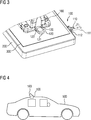
- a top view of the one-hand mounting system 100 shows that an antenna module 160 can be fixed to the roof 300 of the vehicle by means of the rotatable fixing device 120, which further comprises a protrusion 126, arranged at a first end of the cylindrical body (also shown in Fig. 2 ) and on the roof 300 of the vehicle.
- the rotatable locking device 120 has two positions, a third position 121, in which the protrusion 126 is not arranged on the antenna module 160 and the antenna module 126 is not fixed or can be released completely from the vehicle, and a fourth position 122, in which the antenna module 160 is fixed to the vehicle by means of the protrusion 126.
- the third position 121 and the fourth position 122 of the rotatable locking device 120 are correlated, respectively, with the first position 111 and the second position 112 of the slidable lever 100.
- the slidable lever 110 is pushed by one-hand from the side of the chassis 200 and performs the translational movement from the first position 111 to the second position 112, resulting in the rotational movement of the rotatable locking device 120 and the pivoting of the protrusion 125 from the third position 121 to the fourth position 122 around a pivoting angle between 90° and 180°.
- Fig. 4 shows a vehicle 500, which comprises a one-hand mounting system 100, and an antenna module 160, which is fixed on the roof of the vehicle 500 by means of the one-hand mounting system 100.
Landscapes
- Engineering & Computer Science (AREA)
- Remote Sensing (AREA)
- Support Of Aerials (AREA)
Abstract
Description
- The present invention relates to the field of automotive assembly. Particularly, the invention relates to a one-hand mounting system for fixing an antenna module to a vehicle and to a vehicle comprising a one-hand mounting system.
- An antenna module, especially an intelligent antenna module, is widely implemented as a standalone telematics unit in vehicles and represents an interface between the vehicle and the outside information carriers, e.g. infrastructure (WiFi, WLAN n/ac), other cars (WLAN p), smartphones (BTLE and WiFi), cellular networks (LTE/UMTS) satellite navigation (GNSS), or radio broadcast (AM/FM). In order to mount the antenna module to the vehicle, a hole in the PCB (printed circuit board) of the antenna module may be provided to allow fastening it with screws or other tools to the vehicle.
- It is an objective of the invention to provide a simple, efficient and compact mounting solution for fixing an antenna module to a vehicle.
- The problem is solved by the subject matter according to the independent claim. The dependent claims, the following description and the drawings show embodiments of the invention.
- According to a first aspect, a one-hand mounting system for fixing an antenna module to a vehicle is provided. The system comprises a slidable lever and a rotatable locking device.
- By applying the one-hand mounting system to fix or release the antenna module to or from the vehicle, the slidable lever is configured to perform a translational movement, which may be driven by pushing or pulling an open end of the slidable lever under a one-hand operation.
- The rotatable locking device ist configured to be engaged with the slidable lever. The rotatable locking device is arranged in direct contact with the slidable lever. The translational movement can thus be transferred and drive further the rotatable locking device to rotate or pivot. In other words, the rotatable locking device is configured to transform or convert the translational movement of the slidable lever to the rotational movement of the rotatable locking device.
- According to an embodiment, the slidable lever comprises a gear rack or at least a region of gear rack. Correspondingly, the rotatable locking device comprises a gear, which is arranged adjacent to the gear rack or the region of gear rack, so that the rotatable locking device is engaged with the gear rack of the slidable lever.
- Alternatively, an increased friction between the contacting surfaces of the slidable lever and the rotatable locking device may also allow the transformation from the translational movement of the slidable lever to the rotational movement of the rotatable locking device.
- According to another embodiment, the slidable lever is arranged in a cavity of a chassis of the vehicle and below a roof of the vehicle.
- The cavity of the chassis, arranged below the vehicle roof, can be designed as a groove, the width of which may be defined to be identical to the width of the slidable lever. The defined width of the cavity prevents a transversal movement of the slidable lever perpendicular to the longitudinal extension of the slidable lever.
- The length of the cavity may also be defined, so that the cavity is configured to stop the translational movement of the rotatable locking device and the antenna module can be tightly and appropriately fastened to the roof of the vehicle. The defined length of the slidable lever enables a reproducible and robust mounting of the antenna module.
- According to another embodiment, the slidable lever further comprises a recess, which is configured to receive a rib of the chassis, and an end section, which is configured to fit in a slot of the cavity of the chassis. The slidable lever and the end section of the slidable lever are configured to generate a resistance change and a tactile feedback in turn, which may indicate the accomplished translational movement or the accomplishment of mounting the antenna module.
- The resistence change may arise from the translational movement of the slidable lever to fix the antenna module. The resistence starts at a point, where the recess meets the rib of the chassis, and increases until a sudden decrease or a release, indicating that the rib of the chassi is arranged completely in the recess of the slidable lever and the end section of the slidable lever is arranged into a slot of the cavity. The resistance change may be reflected as a tactile feedback to a mounting operator, indicating clearly whether the mounting process is accomplished. This tactile feedback can significantly improve the robustness and the efficiency in mounting the antenna module.
- According to another embodiment, the one-hand mounting system further comprises at least one supporting element, e.g. two supporting elements. The supporting elements are configured to mount the slidable lever to the cavity of the chassis and to prevent a movement of the slidable lever perpendicular to the longitudinal extension of the slidable lever.
- According to another embodiment, the rotatable locking device is arranged in a first recess in the chassis and a second recess in the roof of the vehicle.
- According to another embodiment, the rotatable locking device comprises a cylindrical body with a protrusion at a first end of the cylindrical body, which is arranged on the roof of the vehicle.
- According to another embodiment, the protrusion of the rotatable locking device is configured to fix the antenna module on the vehicle.
- The rotatable locking device with its protrusion is configured as the only component of the one-hand mounting system, which is arranged on the roof of the vehicle. This enables thus a compact design of the mounting system for fixing the antennal module.
- According to another embodiment, the slidable lever is configured to perform the translational movement from a first position to a second position, when fixing the antenna module onto the roof. Correspondingly, the protrusion of the rotatable fixing device is configured to pivot from a third position to a fourth position.
- The first position of the slidable lever is correlated with the third position of the protrusion, representing that the antenna module is not fixed to the vehicle. At the first position or the third position, the open end of the slidable lever is arranged distant from the cavity of the chassis, the rib of the chassis is not arranged in the recess of the slidable lever and the end section of the slidable lever is not arranged in the slot of the cavity. The slidable lever is flexible to move.
- The second position of the slidable lever is correlated with the fourth position of the protrusion, representing that the antenna module is tightly fixed to the vehicle. At the second position or the fourth position, the open end of the slidable end is pushed to be close to the cavity of the chassis, the rib of the chassis is completely arranged in the recess of the slidable lever and the end section of the slidable lever is arranged in the slot of the cavity. The slidable lever is fixed.
- The translational movement of the slidable lever from the first position to the second position can be directly transformed to the rotational movement of the rotatable locking device and further to the pivoting of the protrusion from the third position to the fourth position.
- According to another embodiment, the pivoting angle of the protrusion between the third position and the fourth position is between 90° and 180°.
- The maximal pivoting angle of the protrusion may be dependent on the length of the cavity or the length of the slidable lever. A smaller pivoting angle and a shorter slidable lever may result in a compacter mounting system.
- According to a second aspect, a vehicle comprising a one-hand mounting system is provided.
- These and other aspects will be apparent from and elucidated with reference to the embodiments as per the drawing described hereinafter. In the following description exemplary embodiments are explained with reference to the accompanying schematic drawing in which
-
Fig. 1 shows schematically a rear view of a one-hand mounting system for fixing an antenna module to a vehicle in accordance with an embodiment, -
Fig. 2 shows schematically a side view of a one-hand mounting system for fixing an antenna module to a vehicle in accordance with an embodiment, -
Fig. 3 shows schematically a top view of a one-hand mounting system for fixing an antenna module to a vehicle in accordance with an embodiment, -
Fig. 4 shows schematically a vehicle comprising a one-hand mounting system in accordance with an embodiment. -
Fig. 1 shows a rear view of a one-hand mounting system 100, which is configured to fix an antenna module to a vehicle.
The one-hand mounting system 100 comprises aslidable lever 110 having a region ofgear rack 115, arotatable locking device 120, which is arranged adjacent to the region ofgear rack 115, and two supportingelements 130. - The
slidable lever 110 is arranged in acavity 210 of thechassis 200 and projects with an open end laterally into the outside of thechassis 200. Thecavity 210 is designed as a groove with the width identical to the width of theslidable lever 110, as to prevent a transversal movement of theslidable lever 110 perpendicular to the longitudinal extension of theslidable lever 110. The length of thecavity 210 is shorter than the length of theslidable lever 110 and can also be defined, so that thecavity 210 can stop the translational movement of therotatable locking device 120, when the antenna module is fixed to the vehicle. - The
rotatable locking device 120 comprises a gear, which is engaged with thegear rack 115 of theslidable lever 110. - The supporting
elements 130 is fixed on thecavity 210, in which theslidable lever 110 is placed inside. Theslidable lever 110 is then mounted to thecavity 210 and can be prevented from moving in a direction perpendicular to the longitudinal extension of theslidable lever 110. - Furthermore, the
slidable lever 110 may perform a translational movement between two positions: afirst position 111 or an "off-position", in which the open end of theslidable lever 110 is arranged distant from the cavity of the chassis and the antenna module is not fixed or can be released completely from the vehicle, and asecond position 112 or an "on-position" 112, in which the open end of theslidabel lever 110 is closer to thecavity 210 and the antenna module is fixed to the vehicle. When fixing the antenna module to the vehicle, theslidable lever 110 is pushed by one-hand towards thecavity 210 and performs a translational movement from thefirst position 111 to thesecond position 112. -
Fig. 2 shows a side view of the one-hand mounting system 100 shown inFig. 1 . It is observable that the one-hand mounting system 100 is arranged inside and under thechassis 200, which is arranged below theroof 300 of the vehicle. Theslidable lever 110 further comprises arecess 113, which can receive arib 201 of the chassis when theslidable lever 110 is pushed to thesecond position 112 and the antenna module is mounted. - Additionally, the
slidable lever 110 further comprises anend section 114, which is configured to fit in aslot 202 of the cavity when theslidable lever 110 is pushed to thesecond position 112 and the antenna module is mounted. - In
Fig. 2 , therotatable fixing device 120 comprises a cylindrical body and aprotrusion 126, which is shown in more detail inFig. 3 . With the cylindrical body, therotatable locking device 120 is arranged in a first recess in thechassis 200 and a second recess in theroof 300 of the vehicle. Therefore, the rotatable fixing lever is the only component of the one-hand mounting system 100, which is arranged on theroof 300 of the vehicle and configured to be in direct contact with the antenna module by fixing it. - In
Fig. 3 , a top view of the one-hand mounting system 100 shows that anantenna module 160 can be fixed to theroof 300 of the vehicle by means of therotatable fixing device 120, which further comprises aprotrusion 126, arranged at a first end of the cylindrical body (also shown inFig. 2 ) and on theroof 300 of the vehicle. - The
rotatable locking device 120 has two positions, athird position 121, in which theprotrusion 126 is not arranged on theantenna module 160 and theantenna module 126 is not fixed or can be released completely from the vehicle, and afourth position 122, in which theantenna module 160 is fixed to the vehicle by means of theprotrusion 126. - Since the translational movement of the
slidable lever 110 can be transformed into a rotational movement of therotatable locking device 120 via the engagedgear rack 115 and the gear, thethird position 121 and thefourth position 122 of therotatable locking device 120 are correlated, respectively, with thefirst position 111 and thesecond position 112 of theslidable lever 100. In other words, when fixing theantenna module 160, theslidable lever 110 is pushed by one-hand from the side of thechassis 200 and performs the translational movement from thefirst position 111 to thesecond position 112, resulting in the rotational movement of therotatable locking device 120 and the pivoting of the protrusion 125 from thethird position 121 to thefourth position 122 around a pivoting angle between 90° and 180°. -
Fig. 4 shows avehicle 500, which comprises a one-hand mounting system 100, and anantenna module 160, which is fixed on the roof of thevehicle 500 by means of the one-hand mounting system 100.
Claims (11)
- One-hand mounting system (100) for fixing an antenna module (160) to a vehicle (500), the system (100) comprising:a slidable lever (110), configured to perform a translational movement;a rotatable locking device (120), engaged with the slidable lever (110) to transform the translational movement of the slidable lever (110) to a rotational movement of the rotatable locking device (120), thereby fixing or releasing the antenna module (160) to or from the vehicle (500).
- The one-hand mounting system (100) according to claim 1,
wherein the slidable lever (110) comprises a gear rack (115); and
wherein the rotatable locking device (120) comprises a gear, which is engaged with the gear rack (115) of the slidable lever (110). - The one-hand mounting system (100) according to claim 1 or 2,
wherein the slidable lever (110) is arranged in a cavity (210) of a chassis (200) of the vehicle (500) and below a roof (300) of the vehicle (500). - The one-hand mounting system (100) according to any of the preceding claims,
wherein the slidable lever (110) further comprises a recess (113), configured to receive a rib (201) of the chassis (200), and an end section (114), configured to fit in a slot (202) of the cavity (210) of the chassis (200);
wherein the slidable lever (110) and the end section (114) of the slidable lever (110) are configured to generate a tactile feedback for indicating accomplishment of mounting the antenna module (160). - The one-hand mounting system (100) according to any of the preceding claims, further comprising:at least one supporting element (130), configured to mount the slidable lever (110) to the cavity (210) of the chassis (200) and to prevent a movement of the slidable lever (110) perpendicular to the longitudinal extension of the slidable lever (110).
- The one-hand mounting system (100) according to any of the preceding claims,
wherein the rotatable locking device (120) is arranged in a first recess in the chassis (200) and a second recess in the roof (300) of the vehicle (500). - The one-hand mounting system (100) according to any of the preceding claims,
wherein the rotatable locking device (120) comprises a cylindrical body with a protrusion (126) at a first end of the cylindrical body, which is arranged on the roof (300) of the vehicle (500). - The one-hand mounting system (100) according to claim 7,
wherein the protrusion (126) of the rotatable locking device (120) is configured to fix the antenna module (160) on the vehicle (500). - The one-hand mounting system (100) according to claim 7 or 8,
wherein the slidable lever (110) is configured to perform the translational movement from a first position (111) to a second position (112), when fixing the antenna module (160) onto the roof (300);
wherein the protrusion (126) of the rotatable fixing device (120) is configured to pivot from a third position (121) to a fourth position (122), when fixing the antenna module (160) onto the roof (300). - The one-hand mounting system (100) according to claim 9,
wherein a pivoting angle between the third position (121) and the fourth position (122) is between 90° and 180°. - A vehicle (500) comprising a one-hand mounting system (100) according to any of the preceding claims.
Priority Applications (4)
| Application Number | Priority Date | Filing Date | Title |
|---|---|---|---|
| EP18198147.3A EP3633787B1 (en) | 2018-10-02 | 2018-10-02 | One-hand mounting system for fixing an antenna module on a vehicle |
| US17/281,377 US11527818B2 (en) | 2018-10-02 | 2019-09-11 | One-hand mounting system for fixing an antenna module on a vehicle |
| CN201980065047.7A CN112753131B (en) | 2018-10-02 | 2019-09-11 | Single hand mounting system for securing an antenna module to a vehicle |
| PCT/EP2019/074243 WO2020069830A1 (en) | 2018-10-02 | 2019-09-11 | One-hand mounting system for fixing an antenna module on a vehicle |
Applications Claiming Priority (1)
| Application Number | Priority Date | Filing Date | Title |
|---|---|---|---|
| EP18198147.3A EP3633787B1 (en) | 2018-10-02 | 2018-10-02 | One-hand mounting system for fixing an antenna module on a vehicle |
Publications (2)
| Publication Number | Publication Date |
|---|---|
| EP3633787A1 true EP3633787A1 (en) | 2020-04-08 |
| EP3633787B1 EP3633787B1 (en) | 2022-02-23 |
Family
ID=63722195
Family Applications (1)
| Application Number | Title | Priority Date | Filing Date |
|---|---|---|---|
| EP18198147.3A Active EP3633787B1 (en) | 2018-10-02 | 2018-10-02 | One-hand mounting system for fixing an antenna module on a vehicle |
Country Status (4)
| Country | Link |
|---|---|
| US (1) | US11527818B2 (en) |
| EP (1) | EP3633787B1 (en) |
| CN (1) | CN112753131B (en) |
| WO (1) | WO2020069830A1 (en) |
Cited By (1)
| Publication number | Priority date | Publication date | Assignee | Title |
|---|---|---|---|---|
| WO2024161976A1 (en) * | 2023-02-02 | 2024-08-08 | 原田工業株式会社 | Housing structure for vehicular antenna |
Citations (3)
| Publication number | Priority date | Publication date | Assignee | Title |
|---|---|---|---|---|
| US6113402A (en) * | 1997-04-15 | 2000-09-05 | Samsung Electronics Co., Ltd. | Structure for mounting printed circuit board in an electronic appliance |
| KR20090052711A (en) * | 2007-11-21 | 2009-05-26 | 현대자동차주식회사 | Car retractable roof antenna |
| US20180034128A1 (en) * | 2015-02-17 | 2018-02-01 | Peiker Acustic Gmbh & Co. Kg | Antenna module |
Family Cites Families (42)
| Publication number | Priority date | Publication date | Assignee | Title |
|---|---|---|---|---|
| US4114160A (en) * | 1977-01-26 | 1978-09-12 | Verini Anthony J | Automobile antenna mounting bracket apparatus |
| JP2581442Y2 (en) * | 1992-06-03 | 1998-09-21 | 株式会社豊田自動織機製作所 | Car antenna |
| JP3047860B2 (en) * | 1997-06-26 | 2000-06-05 | 日本電気株式会社 | Antenna mounting device |
| DE19825439C2 (en) * | 1998-05-29 | 2002-04-18 | Brose Fahrzeugteile | Removable vehicle seat |
| US6509878B1 (en) * | 2001-04-02 | 2003-01-21 | Radiall/Larsen Antenna Technologies, Inc. | Antenna mounting system |
| WO2012125726A1 (en) * | 2011-03-14 | 2012-09-20 | Intelligent Technologies International, Inc. | Cargo theft prevention system and method |
| JP3827159B2 (en) * | 2003-01-23 | 2006-09-27 | 株式会社ヨコオ | In-vehicle antenna device |
| KR20050048177A (en) * | 2003-11-19 | 2005-05-24 | 현대자동차주식회사 | Mobile antenna for automobile |
| JP3859659B2 (en) * | 2004-03-01 | 2006-12-20 | 株式会社錦織 | Antenna fixture |
| KR20050116181A (en) * | 2004-06-07 | 2005-12-12 | 현대자동차주식회사 | System for controlling vehicle antenna position |
| EP1653555A3 (en) * | 2004-10-30 | 2006-05-10 | Hirschmann Car Communication GmbH | apparatus for coupling a wiring harness to an antenna |
| JP2007074639A (en) * | 2005-09-09 | 2007-03-22 | Yokowo Co Ltd | Vehicle-mounted antenna fixing apparatus |
| US8248315B2 (en) * | 2005-11-10 | 2012-08-21 | Laird Technologies, Inc. | Interchangeable slidably mountable fins for antenna assemblies |
| JP5095144B2 (en) * | 2006-07-06 | 2012-12-12 | カルソニックカンセイ株式会社 | Keyless device for vehicle |
| US8059044B2 (en) * | 2008-05-15 | 2011-11-15 | Laird Technologies Gmbh | Antenna mounting apparatus and methods including claw fasteners and/or bayonet locking structures |
| JP5114325B2 (en) * | 2008-07-08 | 2013-01-09 | 原田工業株式会社 | Roof mount antenna device for vehicle |
| CN101770010B (en) * | 2008-12-30 | 2013-12-18 | 中国船舶重工集团公司七五○试验场 | GPS antenna positioning deviation adjusting device |
| KR200454933Y1 (en) * | 2009-08-19 | 2011-08-04 | 주식회사 니프코코리아 | Automotive Tray Cover Locking Device |
| CN102753844B (en) * | 2010-02-12 | 2015-06-17 | 赫希曼汽车通讯有限公司 | Fastening a device having high frequency properties such as an impedance converter or amplifier to a vehicle body |
| JP5480113B2 (en) * | 2010-11-29 | 2014-04-23 | 株式会社ユーシン | Door handle device |
| JP5638968B2 (en) * | 2011-01-19 | 2014-12-10 | 小島プレス工業株式会社 | Vehicle antenna connection device |
| EP2705568B1 (en) * | 2011-05-04 | 2018-07-04 | Hirschmann Car Communication GmbH | Locking a roof antenna of a vehicle by means of a star handle |
| DE102012002953A1 (en) * | 2011-11-09 | 2013-05-16 | Peiker Acustic Gmbh & Co. Kg | Antenna module for a vehicle |
| JP5627641B2 (en) * | 2012-06-07 | 2014-11-19 | 原田工業株式会社 | Roof mount antenna device for vehicle |
| JP5644848B2 (en) * | 2012-12-11 | 2014-12-24 | Smk株式会社 | Vehicle input device |
| DE102013007344A1 (en) * | 2013-04-27 | 2014-10-30 | GM Global Technology Operations LLC (n. d. Gesetzen des Staates Delaware) | Jointing device, wall element and motor vehicle |
| KR101456229B1 (en) * | 2013-05-24 | 2014-10-31 | 인팩일렉스 주식회사 | Antenna for vehicle |
| CN203503775U (en) * | 2013-10-17 | 2014-03-26 | 昆山骅盛电子有限公司 | Fixing device of automobile antenna |
| CN203623538U (en) * | 2013-11-25 | 2014-06-04 | 南京中网卫星通信股份有限公司 | Car roof support device for box-type satellite portable station |
| CN104669222A (en) * | 2013-11-30 | 2015-06-03 | 富泰华工业(深圳)有限公司 | Rotatable platform device |
| CN204114742U (en) * | 2014-10-21 | 2015-01-21 | 广东岭南职业技术学院 | A kind of fish jar LED |
| DE102014018428B4 (en) * | 2014-12-11 | 2018-10-31 | Kathrein Se | antenna module |
| JP2017046142A (en) * | 2015-08-26 | 2017-03-02 | ミツミ電機株式会社 | Antenna device |
| SE539263C2 (en) * | 2015-10-08 | 2017-06-07 | Scania Cv Ab | Fastening device, primarily for installation of an antenna on a vehicle |
| CN205944391U (en) * | 2016-08-24 | 2017-02-08 | 中兴仪器(深圳)有限公司 | Vehicle antenna multi freedom angle and position -adjusting structure |
| CN206893807U (en) * | 2017-07-12 | 2018-01-16 | 福建中锐电子科技有限公司 | A kind of antenna for being easy to adjust angle |
| JP6904839B2 (en) * | 2017-07-31 | 2021-07-21 | 株式会社ヨコオ | Antenna device |
| CN207183494U (en) * | 2017-08-23 | 2018-04-03 | 深圳市新辅升电子科技有限公司 | The vehicle-mounted helical antenna with light source warning function of integration |
| CN207338610U (en) * | 2017-09-08 | 2018-05-08 | 凯士林汽车部件(苏州)有限公司 | Car top antenna Fast Installation structure |
| CN207826118U (en) * | 2018-01-02 | 2018-09-07 | 广州汽车集团股份有限公司 | A kind of roof-rack |
| CN108417959B (en) * | 2018-03-05 | 2019-12-31 | 中国电子科技集团公司第三十八研究所 | A locking device for mobile radar antenna base |
| CN108556861B (en) * | 2018-06-12 | 2025-07-08 | 湖北韵生航天科技有限公司 | Method for preventing dining table board from being collided when seat of rail transit bus rotates and electric dining table board |
-
2018
- 2018-10-02 EP EP18198147.3A patent/EP3633787B1/en active Active
-
2019
- 2019-09-11 CN CN201980065047.7A patent/CN112753131B/en active Active
- 2019-09-11 US US17/281,377 patent/US11527818B2/en active Active
- 2019-09-11 WO PCT/EP2019/074243 patent/WO2020069830A1/en not_active Ceased
Patent Citations (3)
| Publication number | Priority date | Publication date | Assignee | Title |
|---|---|---|---|---|
| US6113402A (en) * | 1997-04-15 | 2000-09-05 | Samsung Electronics Co., Ltd. | Structure for mounting printed circuit board in an electronic appliance |
| KR20090052711A (en) * | 2007-11-21 | 2009-05-26 | 현대자동차주식회사 | Car retractable roof antenna |
| US20180034128A1 (en) * | 2015-02-17 | 2018-02-01 | Peiker Acustic Gmbh & Co. Kg | Antenna module |
Cited By (1)
| Publication number | Priority date | Publication date | Assignee | Title |
|---|---|---|---|---|
| WO2024161976A1 (en) * | 2023-02-02 | 2024-08-08 | 原田工業株式会社 | Housing structure for vehicular antenna |
Also Published As
| Publication number | Publication date |
|---|---|
| CN112753131B (en) | 2024-07-02 |
| CN112753131A (en) | 2021-05-04 |
| US20220037773A1 (en) | 2022-02-03 |
| US11527818B2 (en) | 2022-12-13 |
| EP3633787B1 (en) | 2022-02-23 |
| WO2020069830A1 (en) | 2020-04-09 |
Similar Documents
| Publication | Publication Date | Title |
|---|---|---|
| US8791611B2 (en) | Device for the contact and attachment of an electric component in a motor vehicle | |
| CN105765288B (en) | Height-adjustable supports for mobile equipment | |
| US7052035B2 (en) | Assembly unit having an airbag module and a vehicle steering wheel | |
| US20160172746A1 (en) | Antenna module | |
| WO2010036435A1 (en) | Interchangeable slidably mountable fins for antenna assemblies | |
| JP2008013175A (en) | Supporting device for at least one bicycle | |
| JP6276872B2 (en) | Automotive radar equipment | |
| US11527818B2 (en) | One-hand mounting system for fixing an antenna module on a vehicle | |
| CN103503230A (en) | Locking a roof antenna of a vehicle by means of a star handle | |
| US20200168982A1 (en) | Antenna device and vehicle | |
| US6513961B2 (en) | Lamp unit | |
| KR20130132832A (en) | Flexible device for electrically connecting an electric component and a printed circuit board together, system, and method for mounting a system | |
| US6930264B2 (en) | Switch structure of lamp unit | |
| JP2009099364A (en) | Vehicle antenna connection device | |
| JP5638968B2 (en) | Vehicle antenna connection device | |
| KR100461745B1 (en) | Switch device for steering wheel | |
| EP2714471A1 (en) | A holding means for holding an electronic device to a vehicle component, in particular a windscreen of a vehicle | |
| JP2009018638A (en) | On-vehicle apparatus mounting device | |
| US10870346B2 (en) | Shift lever mounting bracket and shift lever device | |
| EP1909158A1 (en) | Actuating element | |
| EP3599801B1 (en) | Mounting device, mounting arrangement, and method for mounting | |
| CN220096298U (en) | Automobile wire harness buckle convenient to install | |
| JP5191346B2 (en) | Automotive antenna | |
| KR20250068330A (en) | A Cradle for Securing a Mobile Device at a Vehicle with a Structure of Regulating a Height | |
| KR100410881B1 (en) | Clock spring for automobile |
Legal Events
| Date | Code | Title | Description |
|---|---|---|---|
| PUAI | Public reference made under article 153(3) epc to a published international application that has entered the european phase |
Free format text: ORIGINAL CODE: 0009012 |
|
| STAA | Information on the status of an ep patent application or granted ep patent |
Free format text: STATUS: THE APPLICATION HAS BEEN PUBLISHED |
|
| AK | Designated contracting states |
Kind code of ref document: A1 Designated state(s): AL AT BE BG CH CY CZ DE DK EE ES FI FR GB GR HR HU IE IS IT LI LT LU LV MC MK MT NL NO PL PT RO RS SE SI SK SM TR |
|
| AX | Request for extension of the european patent |
Extension state: BA ME |
|
| STAA | Information on the status of an ep patent application or granted ep patent |
Free format text: STATUS: REQUEST FOR EXAMINATION WAS MADE |
|
| 17P | Request for examination filed |
Effective date: 20201008 |
|
| RBV | Designated contracting states (corrected) |
Designated state(s): AL AT BE BG CH CY CZ DE DK EE ES FI FR GB GR HR HU IE IS IT LI LT LU LV MC MK MT NL NO PL PT RO RS SE SI SK SM TR |
|
| GRAP | Despatch of communication of intention to grant a patent |
Free format text: ORIGINAL CODE: EPIDOSNIGR1 |
|
| STAA | Information on the status of an ep patent application or granted ep patent |
Free format text: STATUS: GRANT OF PATENT IS INTENDED |
|
| INTG | Intention to grant announced |
Effective date: 20211116 |
|
| GRAS | Grant fee paid |
Free format text: ORIGINAL CODE: EPIDOSNIGR3 |
|
| GRAA | (expected) grant |
Free format text: ORIGINAL CODE: 0009210 |
|
| STAA | Information on the status of an ep patent application or granted ep patent |
Free format text: STATUS: THE PATENT HAS BEEN GRANTED |
|
| AK | Designated contracting states |
Kind code of ref document: B1 Designated state(s): AL AT BE BG CH CY CZ DE DK EE ES FI FR GB GR HR HU IE IS IT LI LT LU LV MC MK MT NL NO PL PT RO RS SE SI SK SM TR |
|
| REG | Reference to a national code |
Ref country code: GB Ref legal event code: FG4D |
|
| REG | Reference to a national code |
Ref country code: CH Ref legal event code: EP |
|
| REG | Reference to a national code |
Ref country code: AT Ref legal event code: REF Ref document number: 1471148 Country of ref document: AT Kind code of ref document: T Effective date: 20220315 |
|
| REG | Reference to a national code |
Ref country code: IE Ref legal event code: FG4D |
|
| REG | Reference to a national code |
Ref country code: DE Ref legal event code: R096 Ref document number: 602018031145 Country of ref document: DE |
|
| REG | Reference to a national code |
Ref country code: LT Ref legal event code: MG9D |
|
| REG | Reference to a national code |
Ref country code: NL Ref legal event code: MP Effective date: 20220223 |
|
| REG | Reference to a national code |
Ref country code: DE Ref legal event code: R081 Ref document number: 602018031145 Country of ref document: DE Owner name: CONTINENTAL AUTOMOTIVE TECHNOLOGIES GMBH, DE Free format text: FORMER OWNER: CONTINENTAL AUTOMOTIVE GMBH, 30165 HANNOVER, DE Ref country code: DE Ref legal event code: R081 Ref document number: 602018031145 Country of ref document: DE Owner name: AUMOVIO GERMANY GMBH, DE Free format text: FORMER OWNER: CONTINENTAL AUTOMOTIVE GMBH, 30165 HANNOVER, DE |
|
| REG | Reference to a national code |
Ref country code: AT Ref legal event code: MK05 Ref document number: 1471148 Country of ref document: AT Kind code of ref document: T Effective date: 20220223 |
|
| PG25 | Lapsed in a contracting state [announced via postgrant information from national office to epo] |
Ref country code: SE Free format text: LAPSE BECAUSE OF FAILURE TO SUBMIT A TRANSLATION OF THE DESCRIPTION OR TO PAY THE FEE WITHIN THE PRESCRIBED TIME-LIMIT Effective date: 20220223 Ref country code: RS Free format text: LAPSE BECAUSE OF FAILURE TO SUBMIT A TRANSLATION OF THE DESCRIPTION OR TO PAY THE FEE WITHIN THE PRESCRIBED TIME-LIMIT Effective date: 20220223 Ref country code: PT Free format text: LAPSE BECAUSE OF FAILURE TO SUBMIT A TRANSLATION OF THE DESCRIPTION OR TO PAY THE FEE WITHIN THE PRESCRIBED TIME-LIMIT Effective date: 20220623 Ref country code: NO Free format text: LAPSE BECAUSE OF FAILURE TO SUBMIT A TRANSLATION OF THE DESCRIPTION OR TO PAY THE FEE WITHIN THE PRESCRIBED TIME-LIMIT Effective date: 20220523 Ref country code: NL Free format text: LAPSE BECAUSE OF FAILURE TO SUBMIT A TRANSLATION OF THE DESCRIPTION OR TO PAY THE FEE WITHIN THE PRESCRIBED TIME-LIMIT Effective date: 20220223 Ref country code: LT Free format text: LAPSE BECAUSE OF FAILURE TO SUBMIT A TRANSLATION OF THE DESCRIPTION OR TO PAY THE FEE WITHIN THE PRESCRIBED TIME-LIMIT Effective date: 20220223 Ref country code: HR Free format text: LAPSE BECAUSE OF FAILURE TO SUBMIT A TRANSLATION OF THE DESCRIPTION OR TO PAY THE FEE WITHIN THE PRESCRIBED TIME-LIMIT Effective date: 20220223 Ref country code: ES Free format text: LAPSE BECAUSE OF FAILURE TO SUBMIT A TRANSLATION OF THE DESCRIPTION OR TO PAY THE FEE WITHIN THE PRESCRIBED TIME-LIMIT Effective date: 20220223 Ref country code: BG Free format text: LAPSE BECAUSE OF FAILURE TO SUBMIT A TRANSLATION OF THE DESCRIPTION OR TO PAY THE FEE WITHIN THE PRESCRIBED TIME-LIMIT Effective date: 20220523 |
|
| PG25 | Lapsed in a contracting state [announced via postgrant information from national office to epo] |
Ref country code: PL Free format text: LAPSE BECAUSE OF FAILURE TO SUBMIT A TRANSLATION OF THE DESCRIPTION OR TO PAY THE FEE WITHIN THE PRESCRIBED TIME-LIMIT Effective date: 20220223 Ref country code: LV Free format text: LAPSE BECAUSE OF FAILURE TO SUBMIT A TRANSLATION OF THE DESCRIPTION OR TO PAY THE FEE WITHIN THE PRESCRIBED TIME-LIMIT Effective date: 20220223 Ref country code: GR Free format text: LAPSE BECAUSE OF FAILURE TO SUBMIT A TRANSLATION OF THE DESCRIPTION OR TO PAY THE FEE WITHIN THE PRESCRIBED TIME-LIMIT Effective date: 20220524 Ref country code: FI Free format text: LAPSE BECAUSE OF FAILURE TO SUBMIT A TRANSLATION OF THE DESCRIPTION OR TO PAY THE FEE WITHIN THE PRESCRIBED TIME-LIMIT Effective date: 20220223 Ref country code: AT Free format text: LAPSE BECAUSE OF FAILURE TO SUBMIT A TRANSLATION OF THE DESCRIPTION OR TO PAY THE FEE WITHIN THE PRESCRIBED TIME-LIMIT Effective date: 20220223 |
|
| PG25 | Lapsed in a contracting state [announced via postgrant information from national office to epo] |
Ref country code: IS Free format text: LAPSE BECAUSE OF FAILURE TO SUBMIT A TRANSLATION OF THE DESCRIPTION OR TO PAY THE FEE WITHIN THE PRESCRIBED TIME-LIMIT Effective date: 20220623 |
|
| PG25 | Lapsed in a contracting state [announced via postgrant information from national office to epo] |
Ref country code: SM Free format text: LAPSE BECAUSE OF FAILURE TO SUBMIT A TRANSLATION OF THE DESCRIPTION OR TO PAY THE FEE WITHIN THE PRESCRIBED TIME-LIMIT Effective date: 20220223 Ref country code: SK Free format text: LAPSE BECAUSE OF FAILURE TO SUBMIT A TRANSLATION OF THE DESCRIPTION OR TO PAY THE FEE WITHIN THE PRESCRIBED TIME-LIMIT Effective date: 20220223 Ref country code: RO Free format text: LAPSE BECAUSE OF FAILURE TO SUBMIT A TRANSLATION OF THE DESCRIPTION OR TO PAY THE FEE WITHIN THE PRESCRIBED TIME-LIMIT Effective date: 20220223 Ref country code: EE Free format text: LAPSE BECAUSE OF FAILURE TO SUBMIT A TRANSLATION OF THE DESCRIPTION OR TO PAY THE FEE WITHIN THE PRESCRIBED TIME-LIMIT Effective date: 20220223 Ref country code: DK Free format text: LAPSE BECAUSE OF FAILURE TO SUBMIT A TRANSLATION OF THE DESCRIPTION OR TO PAY THE FEE WITHIN THE PRESCRIBED TIME-LIMIT Effective date: 20220223 Ref country code: CZ Free format text: LAPSE BECAUSE OF FAILURE TO SUBMIT A TRANSLATION OF THE DESCRIPTION OR TO PAY THE FEE WITHIN THE PRESCRIBED TIME-LIMIT Effective date: 20220223 |
|
| REG | Reference to a national code |
Ref country code: DE Ref legal event code: R097 Ref document number: 602018031145 Country of ref document: DE |
|
| PG25 | Lapsed in a contracting state [announced via postgrant information from national office to epo] |
Ref country code: AL Free format text: LAPSE BECAUSE OF FAILURE TO SUBMIT A TRANSLATION OF THE DESCRIPTION OR TO PAY THE FEE WITHIN THE PRESCRIBED TIME-LIMIT Effective date: 20220223 |
|
| PLBE | No opposition filed within time limit |
Free format text: ORIGINAL CODE: 0009261 |
|
| STAA | Information on the status of an ep patent application or granted ep patent |
Free format text: STATUS: NO OPPOSITION FILED WITHIN TIME LIMIT |
|
| 26N | No opposition filed |
Effective date: 20221124 |
|
| PG25 | Lapsed in a contracting state [announced via postgrant information from national office to epo] |
Ref country code: SI Free format text: LAPSE BECAUSE OF FAILURE TO SUBMIT A TRANSLATION OF THE DESCRIPTION OR TO PAY THE FEE WITHIN THE PRESCRIBED TIME-LIMIT Effective date: 20220223 |
|
| REG | Reference to a national code |
Ref country code: GB Ref legal event code: 732E Free format text: REGISTERED BETWEEN 20230223 AND 20230301 |
|
| PG25 | Lapsed in a contracting state [announced via postgrant information from national office to epo] |
Ref country code: MC Free format text: LAPSE BECAUSE OF FAILURE TO SUBMIT A TRANSLATION OF THE DESCRIPTION OR TO PAY THE FEE WITHIN THE PRESCRIBED TIME-LIMIT Effective date: 20220223 |
|
| REG | Reference to a national code |
Ref country code: CH Ref legal event code: PL |
|
| REG | Reference to a national code |
Ref country code: BE Ref legal event code: MM Effective date: 20221031 |
|
| P01 | Opt-out of the competence of the unified patent court (upc) registered |
Effective date: 20230522 |
|
| PG25 | Lapsed in a contracting state [announced via postgrant information from national office to epo] |
Ref country code: LU Free format text: LAPSE BECAUSE OF NON-PAYMENT OF DUE FEES Effective date: 20221002 |
|
| PG25 | Lapsed in a contracting state [announced via postgrant information from national office to epo] |
Ref country code: LI Free format text: LAPSE BECAUSE OF NON-PAYMENT OF DUE FEES Effective date: 20221031 Ref country code: IT Free format text: LAPSE BECAUSE OF FAILURE TO SUBMIT A TRANSLATION OF THE DESCRIPTION OR TO PAY THE FEE WITHIN THE PRESCRIBED TIME-LIMIT Effective date: 20220223 Ref country code: FR Free format text: LAPSE BECAUSE OF NON-PAYMENT OF DUE FEES Effective date: 20221031 Ref country code: CH Free format text: LAPSE BECAUSE OF NON-PAYMENT OF DUE FEES Effective date: 20221031 |
|
| PG25 | Lapsed in a contracting state [announced via postgrant information from national office to epo] |
Ref country code: BE Free format text: LAPSE BECAUSE OF NON-PAYMENT OF DUE FEES Effective date: 20221031 |
|
| PG25 | Lapsed in a contracting state [announced via postgrant information from national office to epo] |
Ref country code: IE Free format text: LAPSE BECAUSE OF NON-PAYMENT OF DUE FEES Effective date: 20221002 |
|
| REG | Reference to a national code |
Ref country code: DE Ref legal event code: R081 Ref document number: 602018031145 Country of ref document: DE Owner name: CONTINENTAL AUTOMOTIVE TECHNOLOGIES GMBH, DE Free format text: FORMER OWNER: CONTINENTAL AUTOMOTIVE TECHNOLOGIES GMBH, 30165 HANNOVER, DE Ref country code: DE Ref legal event code: R081 Ref document number: 602018031145 Country of ref document: DE Owner name: AUMOVIO GERMANY GMBH, DE Free format text: FORMER OWNER: CONTINENTAL AUTOMOTIVE TECHNOLOGIES GMBH, 30165 HANNOVER, DE |
|
| PG25 | Lapsed in a contracting state [announced via postgrant information from national office to epo] |
Ref country code: HU Free format text: LAPSE BECAUSE OF FAILURE TO SUBMIT A TRANSLATION OF THE DESCRIPTION OR TO PAY THE FEE WITHIN THE PRESCRIBED TIME-LIMIT; INVALID AB INITIO Effective date: 20181002 |
|
| PG25 | Lapsed in a contracting state [announced via postgrant information from national office to epo] |
Ref country code: CY Free format text: LAPSE BECAUSE OF FAILURE TO SUBMIT A TRANSLATION OF THE DESCRIPTION OR TO PAY THE FEE WITHIN THE PRESCRIBED TIME-LIMIT Effective date: 20220223 |
|
| PG25 | Lapsed in a contracting state [announced via postgrant information from national office to epo] |
Ref country code: MK Free format text: LAPSE BECAUSE OF FAILURE TO SUBMIT A TRANSLATION OF THE DESCRIPTION OR TO PAY THE FEE WITHIN THE PRESCRIBED TIME-LIMIT Effective date: 20220223 |
|
| PG25 | Lapsed in a contracting state [announced via postgrant information from national office to epo] |
Ref country code: MT Free format text: LAPSE BECAUSE OF FAILURE TO SUBMIT A TRANSLATION OF THE DESCRIPTION OR TO PAY THE FEE WITHIN THE PRESCRIBED TIME-LIMIT Effective date: 20220223 |
|
| PG25 | Lapsed in a contracting state [announced via postgrant information from national office to epo] |
Ref country code: TR Free format text: LAPSE BECAUSE OF FAILURE TO SUBMIT A TRANSLATION OF THE DESCRIPTION OR TO PAY THE FEE WITHIN THE PRESCRIBED TIME-LIMIT Effective date: 20220223 |
|
| PGFP | Annual fee paid to national office [announced via postgrant information from national office to epo] |
Ref country code: DE Payment date: 20251031 Year of fee payment: 8 |
|
| PGFP | Annual fee paid to national office [announced via postgrant information from national office to epo] |
Ref country code: GB Payment date: 20251021 Year of fee payment: 8 |
|
| REG | Reference to a national code |
Ref country code: DE Ref legal event code: R081 Ref document number: 602018031145 Country of ref document: DE Owner name: AUMOVIO GERMANY GMBH, DE Free format text: FORMER OWNER: CONTINENTAL AUTOMOTIVE TECHNOLOGIES GMBH, 30175 HANNOVER, DE |