EP3633484A1 - Position control apparatus - Google Patents
Position control apparatus Download PDFInfo
- Publication number
- EP3633484A1 EP3633484A1 EP18808789.4A EP18808789A EP3633484A1 EP 3633484 A1 EP3633484 A1 EP 3633484A1 EP 18808789 A EP18808789 A EP 18808789A EP 3633484 A1 EP3633484 A1 EP 3633484A1
- Authority
- EP
- European Patent Office
- Prior art keywords
- gain
- unit
- oil temperature
- closed
- value
- Prior art date
- Legal status (The legal status is an assumption and is not a legal conclusion. Google has not performed a legal analysis and makes no representation as to the accuracy of the status listed.)
- Granted
Links
- 230000007423 decrease Effects 0.000 claims abstract description 65
- 230000035945 sensitivity Effects 0.000 claims abstract description 16
- 230000005540 biological transmission Effects 0.000 claims description 127
- 230000008859 change Effects 0.000 claims description 36
- 238000012937 correction Methods 0.000 claims description 18
- 238000010248 power generation Methods 0.000 claims description 11
- 239000003921 oil Substances 0.000 description 131
- 230000014509 gene expression Effects 0.000 description 22
- 230000009467 reduction Effects 0.000 description 16
- 230000007935 neutral effect Effects 0.000 description 14
- 239000011159 matrix material Substances 0.000 description 12
- 230000007246 mechanism Effects 0.000 description 11
- 238000010586 diagram Methods 0.000 description 10
- 101100492715 Saccharomyces cerevisiae (strain ATCC 204508 / S288c) ATG1 gene Proteins 0.000 description 8
- 230000000875 corresponding effect Effects 0.000 description 8
- 238000004904 shortening Methods 0.000 description 8
- 230000004044 response Effects 0.000 description 7
- 238000013459 approach Methods 0.000 description 6
- 230000002596 correlated effect Effects 0.000 description 5
- 230000004043 responsiveness Effects 0.000 description 5
- 230000010354 integration Effects 0.000 description 3
- 238000005096 rolling process Methods 0.000 description 3
- 101100203325 Saccharomyces cerevisiae (strain ATCC 204508 / S288c) SKT5 gene Proteins 0.000 description 2
- 238000013461 design Methods 0.000 description 2
- 230000002123 temporal effect Effects 0.000 description 2
- 238000012360 testing method Methods 0.000 description 2
- 230000009471 action Effects 0.000 description 1
- 230000001276 controlling effect Effects 0.000 description 1
- 230000003111 delayed effect Effects 0.000 description 1
- 238000001514 detection method Methods 0.000 description 1
- 238000006073 displacement reaction Methods 0.000 description 1
- 230000000694 effects Effects 0.000 description 1
- 239000010720 hydraulic oil Substances 0.000 description 1
- 238000000034 method Methods 0.000 description 1
- 238000012545 processing Methods 0.000 description 1
- 238000010008 shearing Methods 0.000 description 1
- 238000012546 transfer Methods 0.000 description 1
Images


Classifications
-
- F—MECHANICAL ENGINEERING; LIGHTING; HEATING; WEAPONS; BLASTING
- F16—ENGINEERING ELEMENTS AND UNITS; GENERAL MEASURES FOR PRODUCING AND MAINTAINING EFFECTIVE FUNCTIONING OF MACHINES OR INSTALLATIONS; THERMAL INSULATION IN GENERAL
- F16H—GEARING
- F16H61/00—Control functions within control units of change-speed- or reversing-gearings for conveying rotary motion ; Control of exclusively fluid gearing, friction gearing, gearings with endless flexible members or other particular types of gearing
- F16H61/02—Control functions within control units of change-speed- or reversing-gearings for conveying rotary motion ; Control of exclusively fluid gearing, friction gearing, gearings with endless flexible members or other particular types of gearing characterised by the signals used
- F16H61/0262—Control functions within control units of change-speed- or reversing-gearings for conveying rotary motion ; Control of exclusively fluid gearing, friction gearing, gearings with endless flexible members or other particular types of gearing characterised by the signals used the signals being hydraulic
- F16H61/0265—Control functions within control units of change-speed- or reversing-gearings for conveying rotary motion ; Control of exclusively fluid gearing, friction gearing, gearings with endless flexible members or other particular types of gearing characterised by the signals used the signals being hydraulic for gearshift control, e.g. control functions for performing shifting or generation of shift signals
-
- F—MECHANICAL ENGINEERING; LIGHTING; HEATING; WEAPONS; BLASTING
- F16—ENGINEERING ELEMENTS AND UNITS; GENERAL MEASURES FOR PRODUCING AND MAINTAINING EFFECTIVE FUNCTIONING OF MACHINES OR INSTALLATIONS; THERMAL INSULATION IN GENERAL
- F16H—GEARING
- F16H61/00—Control functions within control units of change-speed- or reversing-gearings for conveying rotary motion ; Control of exclusively fluid gearing, friction gearing, gearings with endless flexible members or other particular types of gearing
- F16H61/66—Control functions within control units of change-speed- or reversing-gearings for conveying rotary motion ; Control of exclusively fluid gearing, friction gearing, gearings with endless flexible members or other particular types of gearing specially adapted for continuously variable gearings
- F16H61/664—Friction gearings
- F16H61/6648—Friction gearings controlling of shifting being influenced by a signal derived from the engine and the main coupling
-
- F—MECHANICAL ENGINEERING; LIGHTING; HEATING; WEAPONS; BLASTING
- F16—ENGINEERING ELEMENTS AND UNITS; GENERAL MEASURES FOR PRODUCING AND MAINTAINING EFFECTIVE FUNCTIONING OF MACHINES OR INSTALLATIONS; THERMAL INSULATION IN GENERAL
- F16H—GEARING
- F16H63/00—Control outputs from the control unit to change-speed- or reversing-gearings for conveying rotary motion or to other devices than the final output mechanism
- F16H63/02—Final output mechanisms therefor; Actuating means for the final output mechanisms
- F16H63/04—Final output mechanisms therefor; Actuating means for the final output mechanisms a single final output mechanism being moved by a single final actuating mechanism
- F16H63/06—Final output mechanisms therefor; Actuating means for the final output mechanisms a single final output mechanism being moved by a single final actuating mechanism the final output mechanism having an indefinite number of positions
- F16H63/065—Final output mechanisms therefor; Actuating means for the final output mechanisms a single final output mechanism being moved by a single final actuating mechanism the final output mechanism having an indefinite number of positions hydraulic actuating means
-
- G—PHYSICS
- G05—CONTROLLING; REGULATING
- G05D—SYSTEMS FOR CONTROLLING OR REGULATING NON-ELECTRIC VARIABLES
- G05D3/00—Control of position or direction
- G05D3/12—Control of position or direction using feedback
- G05D3/20—Control of position or direction using feedback using a digital comparing device
-
- B—PERFORMING OPERATIONS; TRANSPORTING
- B60—VEHICLES IN GENERAL
- B60W—CONJOINT CONTROL OF VEHICLE SUB-UNITS OF DIFFERENT TYPE OR DIFFERENT FUNCTION; CONTROL SYSTEMS SPECIALLY ADAPTED FOR HYBRID VEHICLES; ROAD VEHICLE DRIVE CONTROL SYSTEMS FOR PURPOSES NOT RELATED TO THE CONTROL OF A PARTICULAR SUB-UNIT
- B60W10/00—Conjoint control of vehicle sub-units of different type or different function
- B60W10/10—Conjoint control of vehicle sub-units of different type or different function including control of change-speed gearings
- B60W10/101—Infinitely variable gearings
- B60W10/108—Friction gearings
- B60W10/109—Friction gearings of the toroïd type
-
- B—PERFORMING OPERATIONS; TRANSPORTING
- B60—VEHICLES IN GENERAL
- B60W—CONJOINT CONTROL OF VEHICLE SUB-UNITS OF DIFFERENT TYPE OR DIFFERENT FUNCTION; CONTROL SYSTEMS SPECIALLY ADAPTED FOR HYBRID VEHICLES; ROAD VEHICLE DRIVE CONTROL SYSTEMS FOR PURPOSES NOT RELATED TO THE CONTROL OF A PARTICULAR SUB-UNIT
- B60W2510/00—Input parameters relating to a particular sub-units
- B60W2510/10—Change speed gearings
- B60W2510/1005—Transmission ratio engaged
-
- B—PERFORMING OPERATIONS; TRANSPORTING
- B60—VEHICLES IN GENERAL
- B60W—CONJOINT CONTROL OF VEHICLE SUB-UNITS OF DIFFERENT TYPE OR DIFFERENT FUNCTION; CONTROL SYSTEMS SPECIALLY ADAPTED FOR HYBRID VEHICLES; ROAD VEHICLE DRIVE CONTROL SYSTEMS FOR PURPOSES NOT RELATED TO THE CONTROL OF A PARTICULAR SUB-UNIT
- B60W2510/00—Input parameters relating to a particular sub-units
- B60W2510/10—Change speed gearings
- B60W2510/107—Temperature
-
- F—MECHANICAL ENGINEERING; LIGHTING; HEATING; WEAPONS; BLASTING
- F16—ENGINEERING ELEMENTS AND UNITS; GENERAL MEASURES FOR PRODUCING AND MAINTAINING EFFECTIVE FUNCTIONING OF MACHINES OR INSTALLATIONS; THERMAL INSULATION IN GENERAL
- F16H—GEARING
- F16H15/00—Gearings for conveying rotary motion with variable gear ratio, or for reversing rotary motion, by friction between rotary members
- F16H15/02—Gearings for conveying rotary motion with variable gear ratio, or for reversing rotary motion, by friction between rotary members without members having orbital motion
- F16H15/04—Gearings providing a continuous range of gear ratios
- F16H15/06—Gearings providing a continuous range of gear ratios in which a member A of uniform effective diameter mounted on a shaft may co-operate with different parts of a member B
- F16H15/32—Gearings providing a continuous range of gear ratios in which a member A of uniform effective diameter mounted on a shaft may co-operate with different parts of a member B in which the member B has a curved friction surface formed as a surface of a body of revolution generated by a curve which is neither a circular arc centered on its axis of revolution nor a straight line
- F16H15/36—Gearings providing a continuous range of gear ratios in which a member A of uniform effective diameter mounted on a shaft may co-operate with different parts of a member B in which the member B has a curved friction surface formed as a surface of a body of revolution generated by a curve which is neither a circular arc centered on its axis of revolution nor a straight line with concave friction surface, e.g. a hollow toroid surface
- F16H15/38—Gearings providing a continuous range of gear ratios in which a member A of uniform effective diameter mounted on a shaft may co-operate with different parts of a member B in which the member B has a curved friction surface formed as a surface of a body of revolution generated by a curve which is neither a circular arc centered on its axis of revolution nor a straight line with concave friction surface, e.g. a hollow toroid surface with two members B having hollow toroid surfaces opposite to each other, the member or members A being adjustably mounted between the surfaces
- F16H2015/383—Gearings providing a continuous range of gear ratios in which a member A of uniform effective diameter mounted on a shaft may co-operate with different parts of a member B in which the member B has a curved friction surface formed as a surface of a body of revolution generated by a curve which is neither a circular arc centered on its axis of revolution nor a straight line with concave friction surface, e.g. a hollow toroid surface with two members B having hollow toroid surfaces opposite to each other, the member or members A being adjustably mounted between the surfaces with two or more sets of toroid gearings arranged in parallel
-
- F—MECHANICAL ENGINEERING; LIGHTING; HEATING; WEAPONS; BLASTING
- F16—ENGINEERING ELEMENTS AND UNITS; GENERAL MEASURES FOR PRODUCING AND MAINTAINING EFFECTIVE FUNCTIONING OF MACHINES OR INSTALLATIONS; THERMAL INSULATION IN GENERAL
- F16H—GEARING
- F16H59/00—Control inputs to control units of change-speed-, or reversing-gearings for conveying rotary motion
- F16H59/68—Inputs being a function of gearing status
- F16H59/70—Inputs being a function of gearing status dependent on the ratio established
- F16H2059/704—Monitoring gear ratio in CVT's
-
- F—MECHANICAL ENGINEERING; LIGHTING; HEATING; WEAPONS; BLASTING
- F16—ENGINEERING ELEMENTS AND UNITS; GENERAL MEASURES FOR PRODUCING AND MAINTAINING EFFECTIVE FUNCTIONING OF MACHINES OR INSTALLATIONS; THERMAL INSULATION IN GENERAL
- F16H—GEARING
- F16H61/00—Control functions within control units of change-speed- or reversing-gearings for conveying rotary motion ; Control of exclusively fluid gearing, friction gearing, gearings with endless flexible members or other particular types of gearing
- F16H2061/0075—Control functions within control units of change-speed- or reversing-gearings for conveying rotary motion ; Control of exclusively fluid gearing, friction gearing, gearings with endless flexible members or other particular types of gearing characterised by a particular control method
- F16H2061/0078—Linear control, e.g. PID, state feedback or Kalman
-
- F—MECHANICAL ENGINEERING; LIGHTING; HEATING; WEAPONS; BLASTING
- F16—ENGINEERING ELEMENTS AND UNITS; GENERAL MEASURES FOR PRODUCING AND MAINTAINING EFFECTIVE FUNCTIONING OF MACHINES OR INSTALLATIONS; THERMAL INSULATION IN GENERAL
- F16H—GEARING
- F16H59/00—Control inputs to control units of change-speed-, or reversing-gearings for conveying rotary motion
- F16H59/68—Inputs being a function of gearing status
- F16H59/70—Inputs being a function of gearing status dependent on the ratio established
-
- F—MECHANICAL ENGINEERING; LIGHTING; HEATING; WEAPONS; BLASTING
- F16—ENGINEERING ELEMENTS AND UNITS; GENERAL MEASURES FOR PRODUCING AND MAINTAINING EFFECTIVE FUNCTIONING OF MACHINES OR INSTALLATIONS; THERMAL INSULATION IN GENERAL
- F16H—GEARING
- F16H59/00—Control inputs to control units of change-speed-, or reversing-gearings for conveying rotary motion
- F16H59/68—Inputs being a function of gearing status
- F16H59/72—Inputs being a function of gearing status dependent on oil characteristics, e.g. temperature, viscosity
Definitions
- the ratio ( ⁇ I ref / ⁇ X ref ) of the change rate of the output (operation command value I ref ) to the change rate of the input (target value X ref ) of the minor closed-loop control LP2 is higher than the ratio ( ⁇ X ref / ⁇ SR ref ) of the change rate of the output (target value X ref ) to the change rate of the input (command value SR ref ) of the major closed-loop control LP1.
- ⁇ is the state of the minimum dimension observer.
- the position estimation unit 42 obtains the estimated values X est of the roller positions (see Expression (15)) by performing calculations in accordance with Expressions (14) and (15).
- the estimated value ⁇ est of the tilt angle is given to the arithmetic circuit 51 having the matrix G from the tilt angle estimation unit 41, and G ⁇ est (see Expression (14)) is given to an addition unit 52 from the arithmetic circuit 51.
- the operation command value I ref of the hydraulic actuator 20 is given from the position control unit 43 to an arithmetic circuit 53 for the estimated matrix ⁇ B, and ⁇ BI ref (see Expression (14)) is given from the arithmetic circuit 53 to the addition unit 52.
- the output of the addition unit 52 is given to an integration circuit 54 having a transfer function 1/s, and the state ⁇ is output from the integration circuit 54.
- the state ⁇ is given to an arithmetic circuit 55 having the estimated matrix ⁇ A, and ⁇ A ⁇ (see Expression (14)) is given from the arithmetic circuit 55 to the addition unit 52.
- the addition unit 52 derives a differential value d ⁇ /dt of the state ⁇ by adding ⁇ A ⁇ , ⁇ BI ref , and G ⁇ est (see Expression (14)), and gives this to the integration circuit 54.
- the increase rate of the calculation gain G 2 per unit temperature decrease is set to increase as the oil temperature T decreases.
- the correspondence relationship between the calculation gain G 2 and the oil temperature T is defined by the gain setting unit 60 using, for example, a two-dimensional map, a table, or an arithmetic expression.
- the low opening-degree region LD is, for example, a region including at least 0% ⁇ ⁇ 20%
- the high opening-degree region HD is, for example, a region including at least 80% ⁇ ⁇ 100%.
- Fig. 9 is a timing chart showing an example of the oil temperature T at the time of startup by the transmission controller 40 shown in Fig. 4 and other temporal changes.
- the reference temperature T1 is, for example, a value within a range of -20 to -10°C.
- the calculation gain G 2 and the internal gain K B of the position estimation unit 42 are adjusted in accordance with the oil temperature T and the valve opening degree (operation command value I ref ), so that the response delay due to the decrease in fluidity of oil at a low temperature is compensated by the gain adjustment. Therefore, it is possible to prevent the instability of the closed-loop control after switching from the warm-up operation to the normal operation while shortening the warm-up operation at the time of low-temperature startup.
- the calculation gain G 1 after correction takes a small value when the oil temperature T is low and the opening degree of the control valve 25 is small, and takes a large value when the oil temperature T is high and the opening degree of the control valve 25 is large.
- the relationship between the correction coefficient C G1 and the operation command value I ref (drive current) is inversely correlated with the relationship between the absolute value of the change rate of the oil flow rate in Fig. 6 and the operation command value I ref (drive current).
- the oil temperature acquisition unit instead of the oil temperature sensor 35, a device that acquires information related to an oil temperature (for example, a temperature proportional to the oil temperature) (for example, a sensor that detects a piping temperature) may be used.
- a sensor that detects the roller positions instead of the position estimation unit 42, a sensor that detects the roller positions may be used. That is, as long as the position acquisition unit acquires the actual values of the roller positions, the position acquisition unit may estimate the actual values of the rollers, or may receive a sensor value detected by a roller position sensor.
- the control target of the hydraulic actuator 20 may be a continuously variable transmission of another form instead of the toroidal continuously variable transmission, or may be a device that requires position control other than the transmission. The continuously variable transmission may drive another one without driving the generator.
Landscapes
- Engineering & Computer Science (AREA)
- General Engineering & Computer Science (AREA)
- Mechanical Engineering (AREA)
- Physics & Mathematics (AREA)
- General Physics & Mathematics (AREA)
- Automation & Control Theory (AREA)
- Control Of Transmission Device (AREA)
- Control Of Position Or Direction (AREA)
Abstract
Description
- The present invention relates to a position controller that performs position control by outputting a drive signal to a control valve of a hydraulic actuator.
- In a toroidal continuously variable transmission, power rollers are displaced by a hydraulic mechanism in order to change the transmission ratio. However, at the time of startup in a cold region, response to the operation of the power roller is delayed due to a decrease in fluidity of the oil, and hence a warm-up operation is required at the time of low-temperature startup. As an example of the warm-up operation, in
Patent Literature 1, in the warm-up operation at the time of low-temperature startup, a spool of a control valve of the hydraulic mechanism is reciprocated within a range in which the transmission is maintained in a speed-reduced state to vibrate the piston. In this manner, low-temperature control to promote warm-up by flowing oil is performed. When the oil temperature reaches the reference temperature, normal control for controlling the control valve so that the transmission ratio approaches the command value by closed-loop control is started. - PTL 1:
JP 4495117 B2 - By the way, in recent years, further shortening of the warm-up operation is desired for the early startup of the transmission, but if the reference temperature at which the warm-up operation is switched to the normal operation is lowered and the normal control is started earlier, the fluidity of the oil Is insufficient, and hence the closed-loop control may become unstable for a while in the initial stage of the normal control. For this reason, there is a limit to shortening the warm-up operation.
- Therefore, an object of the present invention is to prevent the instability of closed-loop control after switching from a warm-up operation to a normal operation while shortening the warm-up operation at the time of low-temperature startup.
- According to one aspect of the present invention, there is provided a position controller that performs position control by outputting a drive signal to a control valve of a hydraulic actuator that changes an operation position of an object, the position controller comprising: an oil temperature acquisition unit that acquires information on an oil temperature of the hydraulic actuator; a position acquisition unit that acquires an actual value of an operation position of the object; a position control unit that calculates an operation command value for the control valve by closed-loop control so as to reduce a deviation between a target value of the operation position of the object and the actual value; and a gain setting unit that changes at least one gain of the closed-loop control so that sensitivity of the closed-loop control increases as the oil temperature decreases. The object may be a transmission element that changes a transmission ratio of a continuously variable transmission in accordance with a position change thereof.
- According to the above-described configuration, the gain of the closed-loop control for calculating the operation command value for the control valve so as to reduce the deviation between the target value and the actual value of the operation position of the object is adjusted to change so that the sensitivity of the closed-loop control increases as the oil temperature decreases. Therefore, it is possible to compensate a response delay due to a decrease in fluidity of oil at a low temperature. Therefore, it is possible to prevent the instability of the closed-loop control after switching from the warm-up operation to the normal operation while shortening the warm-up operation at the time of low-temperature startup.
- The at least one gain may include a first gain used to obtain the operation command value from the deviation, and the gain setting unit may increase the first gain as the oil temperature decreases. For example, the first gain may be a calculation gain of the position control unit.
- According to the above-described configuration, as the oil temperature decreases, the responsiveness of the operation command value to the deviation between the target value and the actual value increases. Therefore, it is possible to suitably compensate a response delay due to a decrease in fluidity of oil at a low temperature.
- The at least one gain may include a second gain used to obtain the actual value input to the position subtraction unit, and the gain setting unit may decrease the second gain as the oil temperature decreases. For example, the position acquisition unit may be a position estimation unit that estimates the actual value of the operation position of the object, and the second gain may include sensitivity of an internal model of the position estimation unit.
- According to the above-described configuration, as the oil temperature decreases, the actual value input to the position subtraction unit is adjusted to increase the deviation, so that the sensitivity of the closed-loop control increases. Therefore, it is possible to compensate a response delay due to a decrease in fluidity of oil at a low temperature.
- The object may be a transmission element that changes a transmission ratio of a continuously variable transmission in accordance with a position change thereof.
- According to the above-described configuration, the closed-loop control of the transmission ratio using the hydraulic actuator can be started stably and quickly at the time of low-temperature startup of the transmission.
- According to another aspect of the present invention, there is provided a position controller that performs position control by outputting a drive signal to a control valve of a hydraulic actuator that changes an operating position of a transmission element so as to change a transmission ratio of a continuously variable transmission, the position controller comprising: an oil temperature acquisition unit that acquires information of an oil temperature of the hydraulic actuator, an actual transmission ratio acquisition unit that acquires an actual value of the transmission ratio; a position acquisition unit that acquires an actual value of an operation position of the transmission element; a target position calculation unit that calculates a target value of the operating position of the transmission element by first closed-loop control so as to reduce a deviation between a command value of the transmission ratio and the actual value of the transmission ratio; a position control unit that calculates an operation command value for the control valve by second closed-loop control so as to reduce a deviation between the target value of the operation position of the transmission element and the actual value of the operation position of the transmission element; and a gain setting unit that changes a gain of the first closed-loop control so that sensitivity of the first closed-loop control decreases as the oil temperature decreases.
- In the configuration in which the second closed-loop control (minor closed-loop control) for calculating the operation command value for the control valve is executed so as to reduce the deviation between the target value and the actual value of the operation position of the transmission element together with the first closed-loop control (major closed-loop control) for calculating the target value of the operation position of the transmission element so as to reduce the deviation between the command value and the actual value of the transmission ratio, the gain of the first closed-loop control is adjusted to change so that the sensitivity of closed-loop control decreases as the oil temperature decreases. Therefore, the responsiveness of the major closed-loop control decreases in accordance with a decrease in the responsiveness of the minor closed-loop control due to a decrease in fluidity of oil, and continuous vibration of the transmission ratio can be prevented. Therefore, it is possible to prevent the instability of the closed-loop control after switching from the warm-up operation to the normal operation while shortening the warm-up operation at the time of low-temperature startup.
- The continuously variable transmission may be a toroidal continuously variable transmission that changes the transmission ratio in accordance with a tilt angle of a power roller, and the transmission element may be the power roller.
- According to the above-described configuration, the closed-loop control of the transmission ratio can be started stably and quickly at the time of low-temperature startup of the toroidal continuously variable transmission.
- Power output from the continuously variable transmission may be input to a generator, and the generator may start a power generation operation with a delay from start of the closed-loop control. The gain adjustment may be performed at least in a period after the closed-loop control is started and before the power generation operation of the generator is started.
- According to the above-described configuration, the power generation operation can be stably started early after the closed-loop control is started.
- In the gain adjustment, correction may be performed so that an absolute value of a change rate of the gain with respect to a change in the oil temperature increases when an opening degree of the control valve is in a second opening-degree region smaller than a first opening-degree region as compared to that when the opening degree of the control valve is in the first opening-degree region.
- According to the above-described configuration, even if the viscosity resistance of the flow path is relatively large in the region where the opening degree of the control valve is small, the influence of viscosity is relieved by the increase in the absolute value of the change rate of the gain in the region where the opening degree of the control valve is small, and the nonlinearity between the valve opening degree and the oil flow rate is relieved. Therefore, it is possible to more suitably prevent the closed-loop control from becoming unstable.
- According to the present invention, it is possible to prevent the instability of the closed-loop control after switching from the warm-up operation to the normal operation while shortening the warm-up operation at the time of low-temperature startup.
-
-
Fig. 1 is a skeleton diagram of an integrated drive generator according to a first embodiment -
Fig. 2 is a hydraulic circuit diagram of the integrated drive generator shown inFig. 1 . -
Fig. 3 is a cross-sectional view of a control valve shown inFig. 2 . -
Fig. 4 is a block diagram of a transmission controller of the integrated drive generator shown inFig. 1 . -
Fig. 5 is a block diagram of an internal model of a position estimator shown inFig. 4 . -
Fig. 6 is a graph showing a test result of the relationship between a command value (drive current) of a control valve and an oil flow rate. -
Fig. 7(A) is a graph showing the relationship between a calculation gain and an oil temperature of a position control unit shown inFig. 4 , andFig. 7(B) is a graph showing the relationship between a correction coefficient of the calculation gain of the position control unit and an operation command value (drive current) of the control valve. -
Fig. 8(A) is a graph showing the relationship between an internal gain and an oil temperature of the position estimation unit shown inFig. 5 , andFig. 8(B) is a graph showing the relationship between a correction coefficient of the internal gain of the position estimation unit and the operation command value (drive current) of the control valve. -
Fig. 9 is a timing chart showing an example of the oil temperature at the time of startup by a transmission controller shown inFig. 4 and other temporal changes. -
Fig. 10 is a block diagram of a transmission controller according toEmbodiment 2. -
Fig. 11(A) is a graph showing the relationship between a calculation gain of a target position calculation unit shown inFig. 9 and an oil temperature, andFig. 11(B) is a graph showing the relationship between a correction coefficient of the calculation gain of the target position calculation unit and a command value (current value) of the control valve. - Hereinafter, embodiments will be described with reference to the drawings.
-
Fig. 1 is a skeleton diagram of an integrateddrive generator 1 according toEmbodiment 1. As shown inFig. 1 , the integrated drive generator (hereinafter referred to as "IDG") 1 is used as an AC power supply for an aircraft. At the time of startup of the IDG1, even if rotational power of an engine rotary shaft of an aircraft starts to be transmitted to the IDG1, until the IDG1 can be stably operated, electrical components in the aircraft are driven by an auxiliary power supply that is different from the IDG1 (for example, an external generator or an auxiliary generator). When the IDG1 can be stably operated, the power supply of the electrical components is switched from the auxiliary power supply to the IDG1. Since the IDG1 is used as a main power supply of the aircraft, the power supply is switched from the auxiliary power supply to the IDG1 before takeoff. - The IDG 1 includes a
casing 2 attached to an engine of an aircraft, and agenerator 3 is accommodated in thecasing 2 together with a constant speed drive (hereinafter, referred to as "CSD") 4. The CSD4 forms a power transmission path that transmits the rotational power of the engine rotary shaft (not shown) of the aircraft to thegenerator 3, and a toroidal continuously variable transmission 10 (hereinafter referred to as "toroidal CVT") forms a part thereof. The rotational power of the engine rotary shaft is input to the toroidal CVT10 via an input path 5 of theCSD 4, is changed in gear by the toroidal CVT10, and is output to agenerator shaft 7 via an output path 6 of the CSD4. When thegenerator shaft 7 rotates, thegenerator 3 generates AC power at a frequency which is proportional to the rotation speed of thegenerator shaft 7. The transmission ratio SR of the toroidal CVT10 is continuously changed so as to keep the rotation speed of thegenerator shaft 7 at an appropriate value (value corresponding to the frequency at which the electrical components in the aircraft are stably operated) regardless of fluctuations in the rotation speed of the engine rotary shaft. In this way, the frequency of the AC power generated by thegenerator 3 is maintained at an appropriate value, and the electrical components in the aircraft are stably operated. - In the toroidal CVT10, a
CVT input shaft 11 and aCVT output shaft 12 are coaxially arranged on the CVT axis line A1.Input discs 13 are provided on theCVT input shaft 11 so as to be integrally rotatable, andoutput discs 14 are provided on theCVT output shaft 12 so as to be integrally rotatable. Theinput disc 13 and theoutput disc 14 face each other and form anannular cavity 15. In the present embodiment, the toroidal CVT10 is a double cavity type, and includes two sets ofinput discs output discs cavities cavity 15, and eachpower roller 16 is supported by atrunnion 17 so as to be rotatable around the rolling axis line A3. Thetrunnions 17 correspond to thepower rollers 16, respectively, in a one-to-one correspondence. Thetrunnions 17 are supported by thecasing 2 so that each of thetrunnions 17 is displaceable in the extension direction of the tilt axis line A2 and is rotatable around the tilt axis line A2. - The
power rollers 16 are supplied with traction oil, and pushed against thediscs clamping mechanism 18. Theclamping mechanism 18 may be a cam type (sometimes referred to as a loading cam mechanism) or a hydraulic mechanism. As a result, a high-viscosity oil film is formed on the input side contact portion (contact interface between thepower roller 16 and the input disc 13) and the output side contact portion (contact interface between thepower roller 16 and the output disc 14). TheCVT input shaft 11 is driven to rotate by the rotational power input from the input path 5. With the rotation of theCVT input shaft 11, theinput discs 13 rotate together with theCVT input shaft 11 and thepower rollers 16 are driven to rotate around the rolling axis line A3 by a shear resistance of the oil film which is generated in the input side contact portion. With the rotation of thepower rollers 16 around the rolling axis line A3, theoutput discs 14 are driven to rotate by a shearing resistance of the oil film which is generated on the output side contact portion, and theCVT output shaft 12 rotates integrally therewith. The rotational power of theCVT output shaft 12 is output to the output path 6. - The transmission ratio SR is continuously changed in accordance with the roller positions X (positions in the extending directions of the tilt axis lines A2 of the power rollers 16). The transmission ratio SR is defined as the ratio of the output rotation speed (rotation speed of the CVT output shaft 12) N2 to the input rotation speed (rotation speed of the CVT input shaft 11) N1 of the toroidal CVT10, and is equal to the radius ratio (SR = N2/N1 = rin/rout). The radius ratio is a ratio of the input side contact radius rin (distance from the CVT axis line A1 to the input side contact portion) to the output side contact radius rout (distance from the CVT axis line A1 to the output side contact portion). With the change in the roller positions X, the
power rollers 16 rotate around the tilt axis lines A2 until a side slip is ceased, and tilt angles ϕ (rotation angles of thepower rollers 16 around the tilt axis lines A2) are changed. With the change in the tilt angles ϕ, the input side contact portions and the output side contact portions are displaced, and hence the input side contact region radiuses rin and the output side contact region radiuses rout are continuously changed. Therefore, the radius ratio, that is, the transmission ratio SR is continuously changed. -
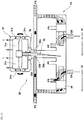
Fig. 2 is a hydraulic circuit diagram of theintegrated drive generator 1 shown inFig. 1 . As shown inFig. 2 , the roller positions X are changed by ahydraulic actuator 20. Thehydraulic actuator 20 includes a plurality ofhydraulic cylinders 21. Thehydraulic cylinders 21 correspond to thepower rollers 16 and thetrunnions 17, respectively, in a one-to-one correspondence. Thehydraulic cylinders 21 each include abody 21a, apiston 21b, and arod 21c. Thehydraulic cylinder 21 is a double-acting type, and the inside of thebody 21a is partitioned into aspeed increase chamber 22 and aspeed reduction chamber 23 by thepiston 21b. Therod 21c is arranged coaxially with the tilt axis line A2, connects thepiston 21b to thetrunnion 17, and moves in the extending direction of the tilt axis line A2 together with thetrunnion 17 and thepower roller 16 supported by thetrunnion 17. - When oil is supplied to the
speed increase chambers 22 and discharged from thespeed reduction chambers 23, the roller positions X are changed to the speed increase side in the extending direction of the tilt axis lines A2. When the oil flows in the opposite direction, the roller positions X are changed to the speed reduction side that is the opposite side to the speed increase side in the extending direction of the tilt axis lines A2. The twopower rollers 16 arranged in onecavity 15 are displaced in opposite directions in the extending direction of the tilt axis lines A2 in order to keep the radius ratio equal to each other when the roller positions X are changed. - When the roller positions X are changed to the speed increase side, the tilt angles ϕ increase and the transmission ratio SR increases. When the roller positions X are changed to the speed reduction side, the tilt angles ϕ decrease and the transmission ratio SR decreases. When the roller positions X reaches the upper limit points Xmax, the tilt angles ϕ become the maximum tilt angles ϕXmax, and the transmission ratio SR exceeds the maximum transmission ratio SRXmax which exceeds 1. When the roller positions X reach the lower limit points Xmin, the tilt angles ϕ become the minimum tilt angles ϕmin, and the transmission ratio SR becomes the minimum transmission ratio SRmin which is less than 1. The allowable tilt range of the
power roller 16 is mechanically determined by a stopper (not shown) provided on thetrunnion 17 to prevent excessive tilting. If the roller positions X are the neutral points Xn, the tilt angles ϕ become the neutral angles ϕn, and the transmission ratio SR becomes 1. The neutral angle ϕn is approximately equal to the median value of the allowable tilt range, and the minimum transmission ratio SRmin is approximately equal to the reciprocal of the maximum transmission ratio SRXmax. - The
hydraulic actuator 20 further includes acontrol valve 25. Thehydraulic cylinders 21 correspond to thepower rollers 16, respectively, in a one-to-one correspondence, whereas thecontrol valve 25 is single for the plurality ofpower rollers 16, for example. Thecontrol valve 25 is a four-way switching valve, and has a supply port PS, a return port PT, a speed-increase control port CA, and a speed-reduction control port CB. Ahydraulic pump 27 that sucks oil from theoil tank 26 is connected to the supply port PS, and the return port PT is connected to theoil tank 26. The speed-increase control port CA is connected to thespeed increase chambers 22, and thespeed reduction chambers 23 are connected to the speed-reduction control port CB. Thecontrol valve 25 is a spool valve, and the connection states of the ports are switched in accordance with the position of aspool 28. Thecontrol valve 25 is a three-position switching valve, and thespool 28 is positioned in the shut-off region (center position inFig. 2 ), the speed increase region (left position inFig. 2 ), or the speed reduction region (right position inFig. 2 ). - In the shut-off region, the control ports CA, CB are cut-off from the supply port PS and the return port PT. At this time, the supply/discharge of oil to/from the
speed increase chamber 22 and thespeed reduction chamber 23 is stopped, and the transmission ratio is maintained. In the speed increase region, the speed-increase control port CA is connected to the supply port PS and the speed-reduction control port CB is connected to the return port PT. At this time, oil is supplied to thespeed increase chamber 22 and discharged from thespeed reduction chamber 23, and the transmission ratio increases. In the speed reduction region, the speed-increase control port CA is connected to the return port PT and the speed-reduction control port CB is connected to the supply port PS. At this time, oil is supplied to thespeed reduction chamber 23 and discharged from thespeed increase chamber 22, and the transmission ratio decreases. When thespool 28 is positioned in the speed increase region or the speed reduction region, the opening degrees of the supply port PS and the return port PT are variably set in accordance with the spool position in the region. - The
control valve 25 includes adrive unit 29 that drives thespool 28 to control the spool position and opening degrees. The flow rate and pressure of oil supplied/discharged to/from thespeed increase chamber 22 and thespeed reduction chamber 23 are adjusted by thedrive unit 29. Thecontrol valve 25 is an electric valve, and thedrive unit 29 receives a drive signal from a transmission controller 40 (position controller) and controls the spool position and opening degrees in accordance with the output value I (current value) of the drive signal. - An IDG2 is provided with an oil temperature sensor 35 (oil temperature acquisition unit) that detects the temperature of the hydraulic oil in the
hydraulic actuator 20. Theoil temperature sensor 35 may be arranged anywhere as long as it can detect the temperature of the oil flowing through the hydraulic circuit of thehydraulic actuator 20, but as an example, theoil temperature sensor 35 is arranged at a position for detecting the temperature of the oil stored in theoil tank 26. -
Fig. 3 is a cross-sectional view of thecontrol valve 25 shown inFig. 2 . As shown inFig. 3 , thecontrol valve 25 is a nozzle flapper type servo valve. Thedrive unit 29 includes amotor unit 31 that generates torque when a drive signal is input, anozzle flapper unit 32 that displaces thespool 28 in accordance with the torque generated by themotor unit 31, and afeedback unit 33 that operates themotor unit 31 and thenozzle flapper unit 32 in accordance with the displacement of thespool 28. - In the
motor unit 31, when a drive signal is input to acoil 31a, a torque corresponding to the polarity and magnitude of the drive signal is generated in anarmature 31d based on the magnetic force acting between upper and lowermagnetic poles armature 31d. As a result, thearmature 31d is inclined with respect to the upper and lowermagnetic poles nozzle flapper unit 32, aflapper 32a integrated with thearmature 31d is displaced in conjunction with the inclination of thearmature 31d. As a result, the amount of orifice restriction between theflapper 32a and aleft nozzle 32b and the amount of orifice restriction between theflapper 32a and aright nozzle 32c change, and the balance of the nozzle back pressures is broken (the nozzle back pressure on the side that theflapper 32a approaches increases and the nozzle back pressure on the side from which theflapper 32a separates away decreases). Both end surfaces of thespool 28 receive the left nozzle back pressure and the right nozzle back pressure, respectively, and thespool 28 starts to be displaced as the nozzle back pressures are imbalanced. Thefeedback unit 33 is configured by, for example, aspring 33a supported by thespool 28 and thearmature 31d. When thespool 28 is displaced, a torque opposite to the torque based on the magnetic force is generated in thespring 33a, and theflapper 32a and thearmature 31d are returned to the neutral position by the torque. Thereby, the balance of the nozzle back pressures is obtained and thespool 28 is stopped. Based on the above-described principle, the spool position and the opening degrees corresponding to the polarity and magnitude of the drive signal can be obtained. - The
hydraulic actuator 20 includes a bias mechanism (not shown) that forcibly holds the roller positions X at predetermined positions when the drive signal satisfies a predetermined condition. For example, the bias mechanism forcibly returns the roller positions X to the lower limit points Xmin when the condition that the output value I is the zero value Iz is satisfied, and maintains the transmission ratio SR at the minimum transmission ratio SRmin on the safe side. Even when the condition that the output value I is a negative value is satisfied, the roller positions X are forcibly returned to the lower limit points Xmin. The bias mechanism is realized by mechanically giving thearmature 31d a constant initial inclination with respect to its neutral position. If the output value I is the zero value Iz, a differential pressure corresponding to the initial inclination occurs between the right and left nozzle back pressures. As a result, thespool 28 is positioned not at the neutral position SPn in the shut-off region but at the bias position in the speed reduction region. - If the output value I becomes the zero value Iz and the
spool 28 is maintained at the bias position, the roller positions X, the tilt angles ϕ, and the transmission ratio SR reach the lower limit points Xmin, the minimum tilt angles ϕmin, and the minimum transmission ratio SRmin, respectively, and are maintained thereat. Conversely, in order to maintain the roller positions X by positioning thespool 28 at the neutral position SPn in the shut-off region, it is necessary to set the output value I of the drive signal so that torque required for canceling the initial tilt is generated in thearmature 31d to continue energizing thecoil 31a with the drive signal. Hereinafter, the output value I for obtaining the neutral position SPn is referred to as "neutral value In". -
Fig. 4 is a block diagram of thetransmission controller 40 of theintegrated drive generator 1 shown inFig. 1 . As shown inFig. 4 , thetransmission controller 40 includes a tiltangle estimation unit 41 that obtains the estimated value ϕest which is a value obtained by estimating the actual value of the tilt angle, a position estimation unit 42 (position acquisition unit) that obtains estimated values Xest which are values obtained by estimating actual values of the roller positions, and aposition control unit 43 that obtains the operation command value Iref of thehydraulic actuator 20 so as to eliminate the deviation ΔX between target values Xref and the estimated values Xest of the roller positions. The tiltangle estimation unit 41 obtains the estimated value ϕest of the tilt angle by calculation without using a sensor that directly detects the tilt angle. The operation command value Iref is, for example, an output value (current value) of a drive signal given to thecontrol valve 25 of thehydraulic actuator 20. - The tilt
angle estimation unit 41 includes an actual transmission ratio calculation unit 44 (actual transmission ratio acquisition unit) that obtains the actual transmission ratio SR, and aconverter 45 that converts the actual transmission ratio SR into the estimated value ϕest of the tilt angle. The actual transmissionratio calculation unit 44 obtains the actual transmission ratio SR in accordance with the ratio between the input rotation speed N1 of the toroidal CVT10 (rotation speed of the engine E) and the output rotation speed N2 of the toroidal CVT10. The input rotation speed N1 and the output rotation speed N2 are detected by an input rotation speed sensor and an output rotation speed sensor, respectively. - The
converter 45 obtains the estimated value ϕest that is a value obtained by estimating the tilt angle in accordance with the actual transmission ratio SR based on the inverse function (ϕ = f-1 (SR)) of the function of the tilt angle ϕ with respect to the actual transmission ratio SR. Theconverter 45 may actually perform the arithmetic operation of the inverse function. Further, in order to reduce the calculation load, a table in accordance with the inverse function may be created in advance and stored in thetransmission controller 40, and the estimated value ϕest may be obtained by table processing. - The
transmission controller 40 includes a target transmissionratio calculation unit 46 that obtains the command value SRref of the transmission ratio. The target transmissionratio calculation unit 46 calculates the command value SRref of the transmission ratio in accordance with the ratio between the input rotation speed N1 detected by the input rotation speed sensor and the command value N2ref of the output rotation speed stored in advance. In the present embodiment, the command value N2ref of the output rotation speed is set to a constant value corresponding to a frequency suitable for the operation of electrical components in the aircraft. For example, when the target frequency fref is 400 Hz, the number of poles of thegenerator 3 is 2, and the detection target of the output rotation speed sensor is the rotation speed of thegenerator shaft 7, the command value N2ref is a constant value of 24,000 rpm. - The
transmission controller 40 includes a transmissionratio subtraction unit 47 that obtains the deviation ΔSR between the command value SRref of the transmission ratio and the actual transmission ratio SR (ΔSR = SRref-SR). Thetransmission controller 40 includes a targetposition calculation unit 48 that calculates the target values Xref of the roller positions so as to reduce the deviation ΔSR of the transmission ratio. That is, the targetposition calculation unit 48 calculates the target values Xref of the roller positions with the predetermined calculation gain G1 so that the deviation ΔSR approaches zero by major closed-loop control LP1 (first closed-loop control; feedback control). In the present embodiment, the calculation gain G1 is constant. - The
transmission controller 40 includes aposition subtraction unit 49 that obtains the deviation ΔX between the target values Xref and the estimated values Xest of the roller positions (ΔX = Xref-Xest). Theposition control unit 43 calculates the operation command value Iref of thehydraulic actuator 20 so as to reduce the deviation ΔX. That is, theposition control unit 43 calculates the operation command value Iref with the predetermined calculation gain G2 so that the deviation ΔX approaches zero by minor closed-loop control LP2 (second closed-loop control; feedback control). The calculation gain G2 will be described later. - The minor closed-loop control LP2 returning to the
position subtraction unit 49 is a loop included in the major closed-loop control LP1 returning to the transmissionratio subtraction unit 47. When thecontrol valve 25 of thehydraulic actuator 20 is given a drive signal indicated by the operation command value Iref, the actual roller positions are brought closer to the target values Xref. Then, the actual transmission ratio SR is brought closer to the command value SRref, and the output rotation speed N2 is brought closer to the command value N2ref. For control stability, it is desired that the sensitivity of the minor closed-loop control LP2 (roller position control) is higher than the sensitivity of the major closed-loop control LP1 (transmission ratio control). That is, it is desired that the ratio (ΔIref/ΔXref) of the change rate of the output (operation command value Iref) to the change rate of the input (target value Xref) of the minor closed-loop control LP2 is higher than the ratio (ΔXref/ΔSRref) of the change rate of the output (target value Xref) to the change rate of the input (command value SRref) of the major closed-loop control LP1. - The
position control unit 43 performs gain adjustment to increase the calculation gain G2 of the operation command value Iref at a predetermined change rate as the oil temperature detected by theoil temperature sensor 35 becomes lower. Specifically, theposition control unit 43 calculates the operation command value Iref based on the calculation gain G2 determined by again setting unit 60 in accordance with the oil temperature T detected by theoil temperature sensor 35. - As described above, the
transmission controller 40 implements a feedback control function for normal control by the tiltangle estimation unit 41, theposition estimation unit 42, theposition control unit 43, the target transmissionratio calculation unit 46, the transmissionratio subtraction unit 47, the targetposition calculation unit 48, and theposition subtraction unit 49, and thetransmission controller 40 further includes a low-temperature control unit 38 that implements a feed-forward control function for low-temperature control at the time of startup. The control by the low-temperature control unit 38 and the control by theposition control unit 43 are switched to each other in accordance with the oil temperature detected by theoil temperature sensor 35. -
Fig. 5 is a block diagram of an internal model of theposition estimation unit 42 shown inFig. 4 . As shown inFig. 5 , theposition estimation unit 42 is an observer created using the models of the tilt angles ϕ and the model of thehydraulic actuator 20, and estimates the roller positions X. The models of the tilt angles ϕ are expressed by Expression (1), and the model of thehydraulic actuator 20 is expressed by Expression (2).
[Math. 1]
[Math. 2]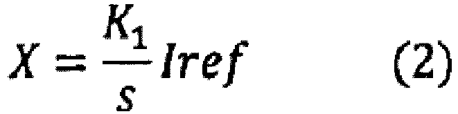
- Here, K1 is a first proportional gain, K2 is a second proportional gain, T2 is a time constant, and s is a Laplace operator.
- With Expressions (1) and (2), a model for designing an observer is expressed by Expression (3).
[Math. 3]
- Here, K = K1K2 and T2≈0.
- Next, the matrices A and B expressed in the state space are divided as shown in Expression (4) to (6).
[Math. 4]
[Math. 5]
[Math. 6]
- Here, x is a state variable. At this time, Expression (7) and (8) hold.
[Math. 7]
[Math. 8]
- Therefore, A11 = A21 = A22 = B1 = 0, A12 = K1, and B2 = K2 hold.
- Next, the determinant design parameter L is introduced as shown in Expression (9), and the observer pole (the eigenvalue of the estimated matrix ^ A) is adjusted to be stable.
[Math. 9]
- Other parameters (estimated matrix ^ B, matrix G, estimated matrix ^ C, and estimated matrix ^ D) are obtained using design parameter L in accordance with Expressions (10) to (13).
[Math. 10]
[Math. 11]
[Math. 12]
[Math. 13]
- From the above, the minimum dimension observer represented by Expressions (14) and (15) is obtained from the models of the tilt angles ϕ (see Expression (1)) and the model of the hydraulic actuator 20 (see Expression (2)).
[Math. 14]
[Math. 15]
- Here, ω is the state of the minimum dimension observer.
- The
position estimation unit 42 obtains the estimated values Xest of the roller positions (see Expression (15)) by performing calculations in accordance with Expressions (14) and (15). In theposition estimation unit 42, the estimated value ϕest of the tilt angle is given to thearithmetic circuit 51 having the matrix G from the tiltangle estimation unit 41, and Gϕest (see Expression (14)) is given to anaddition unit 52 from thearithmetic circuit 51. The operation command value Iref of thehydraulic actuator 20 is given from theposition control unit 43 to anarithmetic circuit 53 for the estimated matrix ^ B, and ^ BIref (see Expression (14)) is given from thearithmetic circuit 53 to theaddition unit 52. The output of theaddition unit 52 is given to anintegration circuit 54 having atransfer function 1/s, and the state ω is output from theintegration circuit 54. The state ω is given to anarithmetic circuit 55 having the estimated matrix ^ A, and ^ Aω (see Expression (14)) is given from thearithmetic circuit 55 to theaddition unit 52. Theaddition unit 52 derives a differential value dω/dt of the state ω by adding ^ Aω, ^ BIref, and Gϕest (see Expression (14)), and gives this to theintegration circuit 54. - The state ω is also given to an
arithmetic circuit 56 for the estimated matrix ^ C, and ^ Cω (see Expression (15)) is given from thearithmetic circuit 56 to anaddition unit 57. The estimated value ϕest of the tilt angle is also supplied from the tiltangle estimation unit 41 to anarithmetic circuit 58 for the estimated matrix ^ D, and ^ Dϕest (see Expression (15)) is supplied from thearithmetic circuit 58 to theaddition unit 57. Theaddition unit 57 derives the estimated values Xest of the roller positions by adding ^ Cω and ^ Dϕest (see Expression (15)), and outputs this to theposition subtraction unit 49. - The
arithmetic circuit 53 for the estimated matrix ^ B derives the matrix ^ B based on the internal gain KB determined by thegain setting unit 61 in accordance with the oil temperature T detected by theoil temperature sensor 35. In this way, theposition estimation unit 42 obtains the estimated values Xest of the roller positions based on the estimated value ϕest of the tilt angle, the operation command value Iref of thehydraulic actuator 20, and the oil temperature T of the hydraulic actuator. -
Fig. 6 is a graph showing a test result of the relationship between the command value (drive current) of thecontrol valve 25 and the oil flow rate.Fig. 6 shows the relationship between the command value of thecontrol valve 25 and the oil flow rate at different oil temperatures T1 to T4 (T1> T2> T3> T4), and it is found that the oil flow rate decreases as the oil temperature decreases. That is, as the oil temperature decreases, the oil viscosity increases and the oil flow rate in thecontrol valve 25 decreases. InFig. 6 , the oil flow rate decreases as the drive current of thecontrol valve 25 approaches the value corresponding to zero valve opening degree, and the change rate of the oil flow rate accompanying the change in the valve opening degree has different nonlinearities between the low opening-degree region LD and the high opening-degree region HD. That is, the absolute value of the decrease rate of the oil flow rate accompanying the decrease in the valve opening degree is smaller in the low opening-degree region LD than in the high opening-degree region HD. In order to correct the influence of the oil temperature and the valve opening degree on the oil flow rate, the calculation gain G2 of theposition control unit 43 and its correction coefficient CG2 are set as follows. -
Fig. 7(A) is a graph showing the relationship between the calculation gain G2 and the oil temperature T of theposition control unit 43 shown inFig. 4 .Fig. 7(B) is a graph showing the relationship between the correction coefficient CG2 of the calculation gain G2 of theposition control unit 43 and the operation command value Iref (drive current) of thecontrol valve 25. As shown inFig. 7(A) , in thegain setting unit 60, the calculation gain G2 of theposition control unit 43 is set in advance so that the calculation gain G2 increases as the oil temperature T decreases. The relationship between the calculation gain G2 and the oil temperature T is similar to the relationship between the viscosity of the oil used in thehydraulic actuator 20 and the oil temperature T. In the present embodiment, the increase rate of the calculation gain G2 per unit temperature decrease is set to increase as the oil temperature T decreases. The correspondence relationship between the calculation gain G2 and the oil temperature T is defined by thegain setting unit 60 using, for example, a two-dimensional map, a table, or an arithmetic expression. - In this way, in the configuration in which the minor closed-loop control LP2 that calculates the operation command value Iref for the
control valve 25 is executed in theposition control unit 43 so as to reduce the deviation ΔX between the target values Xref and the estimated values Xest (actual values) of the roller positions, the calculation gain G2 of the operation command value Iref increases as the oil temperature T decreases, so that the sensitivity (ΔIref/ΔXref) of the closed-loop control increases as the oil temperature T decreases. Therefore, a response delay due to a decrease in fluidity of oil at a low temperature is compensated by an increase in the calculation gain G2. - As shown in
Fig. 7B , the calculation gain G2 of theposition control unit 43 is multiplied by the correction coefficient CG2 that changes in accordance with the operation command value Iref (drive current) of thecontrol valve 25. The correction coefficient CG2 is set so that the absolute value of the change rate of the calculation gain G2 per unit temperature change increases when the opening degree of thecontrol valve 25 is in the low opening-degree region LD (second opening-degree region) smaller than the high opening-degree region as compared to that when the opening degree of thecontrol valve 25 is in the high opening-degree region HD (first opening-degree region). In the present embodiment, when the opening degree α of thecontrol valve 25 is to be fully open at 100% and fully closed at 0%, the low opening-degree region LD is, for example, a region including at least 0% <α <20%, and the high opening-degree region HD is, for example, a region including at least 80% <α <100%. - The calculation gain G2 after correction takes a large value when the oil temperature T is low and the opening degree of the
control valve 25 is small, and takes a small value when the oil temperature T is high and the opening degree of thecontrol valve 25 is large. The relationship between the correction coefficient CG2 and the operation command value Iref (drive current) is inversely correlated with the relationship between the absolute value of the change rate of the oil flow rate inFig. 6 and the operation command value Iref (drive current). In this way, even if the viscosity resistance of the flow path is relatively large in the region where the opening degree of thecontrol valve 25 is small, the influence of viscosity is relieved by the increase in the absolute value of the change rate of the calculation gain G2 in the region where the opening degree of thecontrol valve 25 is small, and the nonlinearity between the valve opening degree and the oil flow rate is relieved. -
Fig. 8(A) is a graph showing the relationship between the internal gain KB and the oil temperature T of theposition estimation unit 42 shown inFig. 5 .Fig. 8(B) is a graph showing the relationship between the internal gain KB of theposition estimation unit 42 and the operation command value Iref (current value) of the control valve. As shown inFig. 8(A) , in thegain setting unit 61, the internal gain KB of thearithmetic circuit 53 of theposition estimation unit 42 is set in advance so that the gain KB decreases as the oil temperature T decreases. The relationship between the internal gain KB and the oil temperature T is inversely correlated with the relationship between the viscosity of the oil used in thehydraulic actuator 20 and the oil temperature T. In the present embodiment, the reduction rate of the internal gain KB per unit temperature decrease is set to increase as the oil temperature T decreases. The correspondence relationship between the internal gain KB and the oil temperature T is also defined by thegain setting unit 61 using, for example, a two-dimensional map, a table, or an arithmetic expression. - In this way, in the configuration in which the minor closed-loop control that calculates the operation command value Iref for the
control valve 25 is executed in theposition control unit 43 so as to reduce the deviation ΔX between the target values Xref and the estimated values Xest (actual values) of the roller positions, as the oil temperature T decreases, the sensitivity (ΔXest/ΔIref) of the internal model of theposition estimation unit 42 decreases. Therefore, theposition estimation unit 42 can perform accurate position estimation in consideration of the oil temperature, and the response delay due to the decrease in fluidity of the oil at a low temperature is further compensated. - As shown in
Fig. 8(B) , the internal gain KB of theposition estimation unit 42 is multiplied by the correction coefficient CKB that changes in accordance with the operation command value Iref (current value) of thecontrol valve 25. Similarly, the correction coefficient CKB is set so that the absolute value of the change rate of the internal gain KB per unit temperature change decreases when the opening degree of thecontrol valve 25 is in the low opening-degree region (first opening-degree region) smaller than the high-opening degree region as compared to that when the opening degree of thecontrol valve 25 is in the high opening-degree region (first opening-degree region). That is, when the oil temperature T is low and the opening degree of thecontrol valve 25 is small, the internal gain KB takes a small value, whereas when the oil temperature T is high and the opening degree of thecontrol valve 25 is large, the internal gain KB takes a large value. The relationship between the correction coefficient CKB and the operation command value Iref (drive current) is inversely correlated with the relationship between the absolute value of the change rate of the oil flow rate inFig. 6 and the operation command value Iref (drive current). - In this way, even if the viscosity resistance of the flow path is relatively large in the region where the opening degree of the
control valve 25 is small, the influence of viscosity is further relieved by the increase in the absolute value of the change rate of the internal gain KB in the region where the opening degree of thecontrol valve 25 is small, and the nonlinearity between the valve opening degree and the oil flow rate is further relieved. -
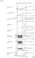
Fig. 9 is a timing chart showing an example of the oil temperature T at the time of startup by thetransmission controller 40 shown inFig. 4 and other temporal changes. As shown inFigs. 4 and9 , when the oil temperature T detected by theoil temperature sensor 35 is lower than the reference temperature T1 at the time of startup of theIDG 1, a warm-up operation in which thecontrol valve 25 is subjected to open-loop control by the low-temperature control unit 38 is executed. The reference temperature T1 is, for example, a value within a range of -20 to -10°C. When the warm-up operation is completed, the normal operation in which thecontrol valve 25 is subjected to closed-loop control by theposition control unit 43 is executed. - In the warm-up operation, the low-
temperature control unit 38 outputs the operation command value I so as to reciprocate thespool 28. The waveform of the operation command value I is set, for example, such that the maximum value Ihigh is a value larger than the neutral value In and the minimum value Ilow is a value smaller than the neutral value In. As a result, oil flows alternately between the speed increase side and the speed reduction side in thecontrol valve 25, and thepiston 21b also vibrates slightly. Thus, the increase in the oil temperature T is promoted by forcibly causing the oil to flow by reciprocating thespool 28. Further, in the waveform of the operation command value I, the difference from the neutral value In of the maximum value Ihigh is smaller than the difference from the neutral value In of the minimum value Ilow. Thespool 28 cannot respond sensitively to the operation command value I. Therefore, thepiston 21b reciprocates on the speed reduction side with respect to the neutral position PSn, and an excessive increase in the output rotation speed N2 is prevented. - When the oil temperature T reaches the reference temperature T1 (t1), the reciprocation of the
spool 28 and thepiston 21b is stopped, and the drive signal is output so that the roller positions X are maintained at predetermined positions (maximum speed-reduction positions) for a predetermined standby time by the action of the bias mechanism described above. Until the standby time elapses, the operation command value I is fixed at the bias mechanism operating value (zero value Iz). When the standby time elapses (t2), the warm-up operation is terminated and the normal operation is started. - In the normal operation, the
position control unit 43 obtains the operation command value Iref by closed-loop control. That is, when theposition control unit 43 outputs the operation command value Iref corresponding to the deviation ΔX, the roller position X is brought closer to the command value Xref, and the transmission ratio SR is brought closer to the command value SRref. However, when the warm-up operation is shortened by setting the reference temperature T1 low, the control immediately after the start of the normal control may become unstable. Therefore, in the present embodiment, in the initial stage of the closed-loop control which is a period after the start of the closed-loop control in the normal operation and before the start of power generation by thegenerator 3, as described above, the calculation gain G2 of theposition control unit 43 and the internal gain KB of theposition estimation unit 42 are adjusted in accordance with the oil temperature T and the valve opening degree (operation command value Iref). Therefore, the control when the output rotation speed N2 approaches the command value N2ref in the initial stage of the closed-loop control is stabilized. When it is determined that the output rotation speed N2 has converged to the command value N2ref (t3), power generation by thegenerator 3 is started, and the frequency of the AC power generated by thegenerator 3 is maintained at the target frequency. - In
Fig. 9 , the values of the calculation gain G2 and the gain KB are stabilized after the start of power generation. This is because the oil temperature T is not low, and in actuality, in the closed-loop control, the adjustment function of the calculation gain G2 and the internal gain KB corresponding to the oil temperature T and the valve opening degree (operation command value Iref) acts even after the start of power generation. - As described above, in the configuration in which the closed-loop control for calculating the operation command value Iref for the
control valve 25 is executed so as to reduce the deviation ΔX between the target values Xref and the estimated values Xest of the operation positions of thepower rollers 16, the calculation gain G2 and the internal gain KB of theposition estimation unit 42 are adjusted in accordance with the oil temperature T and the valve opening degree (operation command value Iref), so that the response delay due to the decrease in fluidity of oil at a low temperature is compensated by the gain adjustment. Therefore, it is possible to prevent the instability of the closed-loop control after switching from the warm-up operation to the normal operation while shortening the warm-up operation at the time of low-temperature startup. The time lag from the start of closed-loop control to the start of a power generation operation can also be stably reduced. Instead of directly adjusting the gain of theposition control unit 43, for example, the gain of theposition control unit 43 may be indirectly adjusted by adding a gain to the signal between theposition subtraction unit 49 and theposition control unit 43. In addition, instead of directly adjusting the gain of theposition estimation unit 42, for example, the sensitivity of the internal model of theposition estimation unit 42 may be indirectly adjusted by adding a gain to the signal between theposition estimation unit 42 and theposition subtraction unit 49. -
Fig. 10 is a block diagram of atransmission controller 140 according toEmbodiment 2.Fig. 11(A) is a graph showing the relationship between a calculation gain of the target position calculation unit shown inFig. 9 and an oil temperature.Fig. 11(B) is a graph showing the relationship between the calculation gain of the target position calculation unit and a command value (current value) of the control valve. Note that configurations that are the same as those inEmbodiment 1 are denoted by the same reference numerals and description thereof is omitted. As shown inFig. 10 , in thetransmission controller 140, the targetposition calculation unit 48 calculates the target value Xref based on the calculation gain G1 determined by again setting unit 160 in accordance with the oil temperature T detected by theoil temperature sensor 35. Note that the calculation gain G2 of theposition control unit 43 is, for example, constant. - As shown in
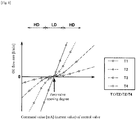
Fig. 11 (A) , in thegain setting unit 160, the calculation gain G1 of the targetposition calculation unit 48 is set in advance so that the calculation gain G1 decreases at a predetermined change rate as the oil temperature T decreases. The relationship between the calculation gain G1 and the oil temperature T is inversely correlated with the relationship between the viscosity of the oil used in thehydraulic actuator 20 and the oil temperature T. In the present embodiment, the absolute value of the decrease rate of the calculation gain G1 per unit temperature decrease is set to decrease as the oil temperature T decreases. - In this way, in the configuration in which the minor closed-loop control LP2 for calculating the operation command value Iref for the
control valve 25 is executed so as to reduce the deviation ΔX between the roller position target values Xref and the estimated values Xest together with the major closed-loop control LP1 for calculating the target values Xref of the roller positions so as to reduce the deviation ΔSR between the command value SRref of the transmission ratio and the actual transmission ratio SR, the calculation gain G1 of the target values Xref decreases as the oil temperature T decreases, and therefore, the sensitivity (ΔXref/ΔSRref) of the major closed-loop control LP1 is adjusted to decrease as the oil temperature T decreases. Therefore, the responsiveness of the major closed-loop control LP1 decreases in accordance with a decrease in the responsiveness of the minor closed-loop control LP2 due to a decrease in fluidity of oil, and continuous vibration of the transmission ratio can be prevented. - As shown in
Fig. 11(B) , the calculation gain G1 of the targetposition calculation unit 48 is multiplied by the correction coefficient CG1 that changes in accordance with the operation command value Iref (drive current) of thecontrol valve 25. The correction coefficient CG1 is set so that the absolute value of the change rate of the calculation gain G1 per unit temperature change decreases when the opening degree of thecontrol valve 25 is in the low opening-degree region LD (second opening-degree region) smaller than the high opening-degree region as compared to that when the opening degree of thecontrol valve 25 is in the high opening-degree region HD (first opening-degree region). That is, the calculation gain G1 after correction takes a small value when the oil temperature T is low and the opening degree of thecontrol valve 25 is small, and takes a large value when the oil temperature T is high and the opening degree of thecontrol valve 25 is large. The relationship between the correction coefficient CG1 and the operation command value Iref (drive current) is inversely correlated with the relationship between the absolute value of the change rate of the oil flow rate inFig. 6 and the operation command value Iref (drive current). - In this way, even if the viscosity resistance of the flow path is relatively large in the region where the opening degree of the
control valve 25 is small, the influence of viscosity is relieved by the increase in the absolute value of the change rate of the calculation gain G1 in the region where the opening degree of thecontrol valve 25 is small, and the nonlinearity between the valve opening degree and the oil flow rate is relieved. Instead of directly adjusting the gain of the targetposition calculation unit 48, for example, the gain of the targetposition calculation unit 48 is indirectly adjusted by adding a gain to the signal between the transmissionratio subtraction unit 47 and the targetposition calculation unit 48. - As described above, it is possible to prevent the instability of the closed-loop control after switching from the warm-up operation to the normal operation while shortening the warm-up operation at the time of low-temperature startup. As a result, the time lag from the start of closed-loop control to the start of a power generation operation can also be stably reduced. Since other configurations are the same as those of
Embodiment 1 described above, description thereof is omitted. - The present invention is not limited to the above-described embodiments, and the configurations can be changed, added, or deleted. Some configurations or methods in one embodiment may be applied to another embodiment, and some configurations in the embodiment can be selectively extracted separately from other configurations in the embodiment. For example, the adjustment of the calculation gain G2 by the
gain setting unit 60, the adjustment of the calculation gain G1 by thegain setting unit 160, and the adjustment of the internal gain KB by thegain setting unit 61 may be selectively combined, and, for example, only one or all of them may be implemented. - As the oil temperature acquisition unit, instead of the
oil temperature sensor 35, a device that acquires information related to an oil temperature (for example, a temperature proportional to the oil temperature) (for example, a sensor that detects a piping temperature) may be used. As the position acquisition unit, instead of theposition estimation unit 42, a sensor that detects the roller positions may be used. That is, as long as the position acquisition unit acquires the actual values of the roller positions, the position acquisition unit may estimate the actual values of the rollers, or may receive a sensor value detected by a roller position sensor. The control target of thehydraulic actuator 20 may be a continuously variable transmission of another form instead of the toroidal continuously variable transmission, or may be a device that requires position control other than the transmission. The continuously variable transmission may drive another one without driving the generator. -
- 1
- integrated drive generator (IDG)
- 3
- generator
- 10
- toroidal continuously variable transmission
- 16
- power roller (transmission element)
- 20
- hydraulic actuator
- 25
- control valve
- 28
- spool
- 35
- oil temperature sensor (oil temperature acquisition unit)
- 40, 140
- transmission controller (position controller)
- 42
- position estimation unit (position acquisition unit)
- 43
- position control unit
- 44
- actual transmission ratio calculation unit (actual transmission ratio acquisition unit)
- 48
- target position calculation unit
- G1, G2
- calculation gain (first gain)
- KB
- internal gain (second gain)
- T
- oil temperature
- HD
- high opening-degree region (first opening-degree region)
- LD
- low opening-degree region (second opening-degree region)
- Iref
- operation command value
- Xref
- target value
- LP1
- major closed-loop control
- LP2
- minor closed-loop control
Claims (10)
- A position controller that performs position control by outputting a drive signal to a control valve of a hydraulic actuator that changes an operation position of an object, the position controller comprising:an oil temperature acquisition unit that acquires information on an oil temperature of the hydraulic actuator;a position acquisition unit that acquires an actual value of an operation position of the object;a position control unit that calculates an operation command value for the control valve by closed-loop control so as to reduce a deviation between a target value of the operation position of the object and the actual value; anda gain setting unit that changes at least one gain of the closed-loop control so that sensitivity of the closed-loop control increases as the oil temperature decreases.
- The position controller according to claim 1,
wherein the at least one gain includes a first gain used to obtain the operation command value from the deviation, and
wherein the gain setting unit increases the first gain as the oil temperature decreases. - The position controller according to claim 2, wherein the first gain is a calculation gain of the position control unit
- The position controller according to any one of claims 1 to 3, further comprising a position subtraction unit that obtains the deviation,
wherein the at least one gain includes a second gain used to obtain the actual value input to the position subtraction unit, and
wherein the gain setting unit decreases the second gain as the oil temperature decreases. - The position controller according to claim 4,
wherein the position acquisition unit is a position estimation unit that estimates the actual value of the operation position of the object, and
wherein the second gain includes sensitivity of an internal model of the position estimation unit. - The position controller according to any one of claims 1 to 5, wherein the object is a transmission element that changes a transmission ratio of a continuously variable transmission in accordance with a position change thereof.
- A position controller that performs position control by outputting a drive signal to a control valve of a hydraulic actuator that changes an operating position of a transmission element so as to change a transmission ratio of a continuously variable transmission, the position controller comprising:an oil temperature acquisition unit that acquires information of an oil temperature of the hydraulic actuator;an actual transmission ratio acquisition unit that acquires an actual value of the transmission ratio;a position acquisition unit that acquires an actual value of an operation position of the transmission element;a target position calculation unit that calculate a target value of the operating position of the transmission element by first closed-loop control so as to reduce a deviation between a command value of the transmission ratio and the actual value of the transmission ratio;a position control unit that calculates an operation command value for the control valve by second closed-loop control so as to reduce a deviation between the target value of the operation position of the transmission element and the actual value of the operation position of the transmission element; anda gain setting unit that changes a gain of the first closed-loop control so that sensitivity of the first closed-loop control decreases as the oil temperature decreases.
- The position controller according to claim 6 or 7, wherein the continuously variable transmission is a toroidal continuously variable transmission that changes the transmission ratio in accordance with a tilt angle of a power roller, and the transmission element is the power roller.
- The position controller according to claim 7 or 8,
wherein power output from the continuously variable transmission is input to a generator, and the generator starts a power generation operation with a delay from start of the closed-loop control, and
wherein the gain adjustment is performed at least in a period after the closed-loop control is started and before the power generation operation of the generator is started. - The position controller according to any one of claims 1 to 9, wherein the gain setting unit performs correction so that an absolute value of a change rate of the gain with respect to a change in the oil temperature increases when an opening degree of the control valve is in a second opening-degree region smaller than a first opening-degree region as compared to that when the opening degree of the control valve is in the first opening-degree region.
Priority Applications (1)
| Application Number | Priority Date | Filing Date | Title |
|---|---|---|---|
| EP22199058.3A EP4134775B1 (en) | 2017-05-31 | 2018-05-16 | Position controller of a continuously variable transmission |
Applications Claiming Priority (2)
| Application Number | Priority Date | Filing Date | Title |
|---|---|---|---|
| JP2017108177A JP6952498B2 (en) | 2017-05-31 | 2017-05-31 | Position control device |
| PCT/JP2018/018953 WO2018221226A1 (en) | 2017-05-31 | 2018-05-16 | Position control apparatus |
Related Child Applications (2)
| Application Number | Title | Priority Date | Filing Date |
|---|---|---|---|
| EP22199058.3A Division EP4134775B1 (en) | 2017-05-31 | 2018-05-16 | Position controller of a continuously variable transmission |
| EP22199058.3A Division-Into EP4134775B1 (en) | 2017-05-31 | 2018-05-16 | Position controller of a continuously variable transmission |
Publications (3)
| Publication Number | Publication Date |
|---|---|
| EP3633484A1 true EP3633484A1 (en) | 2020-04-08 |
| EP3633484A4 EP3633484A4 (en) | 2021-03-10 |
| EP3633484B1 EP3633484B1 (en) | 2023-06-07 |
Family
ID=64455912
Family Applications (2)
| Application Number | Title | Priority Date | Filing Date |
|---|---|---|---|
| EP18808789.4A Active EP3633484B1 (en) | 2017-05-31 | 2018-05-16 | Position controller |
| EP22199058.3A Active EP4134775B1 (en) | 2017-05-31 | 2018-05-16 | Position controller of a continuously variable transmission |
Family Applications After (1)
| Application Number | Title | Priority Date | Filing Date |
|---|---|---|---|
| EP22199058.3A Active EP4134775B1 (en) | 2017-05-31 | 2018-05-16 | Position controller of a continuously variable transmission |
Country Status (4)
| Country | Link |
|---|---|
| US (1) | US11131380B2 (en) |
| EP (2) | EP3633484B1 (en) |
| JP (1) | JP6952498B2 (en) |
| WO (1) | WO2018221226A1 (en) |
Families Citing this family (1)
| Publication number | Priority date | Publication date | Assignee | Title |
|---|---|---|---|---|
| JP6907073B2 (en) * | 2017-08-31 | 2021-07-21 | 川崎重工業株式会社 | Shift control device for toroidal continuously variable transmission |
Family Cites Families (13)
| Publication number | Priority date | Publication date | Assignee | Title |
|---|---|---|---|---|
| JPS6415508A (en) * | 1987-07-07 | 1989-01-19 | Mitsubishi Electric Corp | Electronic controller for flow control valve |
| JP3374677B2 (en) * | 1996-10-31 | 2003-02-10 | 日産自動車株式会社 | Transmission control device for continuously variable transmission |
| JP3460547B2 (en) * | 1997-11-13 | 2003-10-27 | 日産自動車株式会社 | Transmission control device for continuously variable transmission |
| JP3301388B2 (en) * | 1998-07-23 | 2002-07-15 | 日産自動車株式会社 | Transmission control device for continuously variable transmission |
| DE19930374B4 (en) | 1998-07-01 | 2018-12-20 | Nissan Motor Co., Ltd. | Speed ratio controller and control method of a continuously variable toroidal transmission |
| US6312358B1 (en) * | 1999-05-21 | 2001-11-06 | Advanced Technology Institute Of Commuter-Helicopter, Ltd. | Constant speed drive apparatus for aircraft generator and traction speed change apparatus |
| JP2001164953A (en) * | 1999-12-14 | 2001-06-19 | Honda Motor Co Ltd | Valve device for internal combustion engine |
| JP3680739B2 (en) * | 2001-02-06 | 2005-08-10 | 日産自動車株式会社 | Shift control device for continuously variable transmission |
| JP4198937B2 (en) * | 2002-05-17 | 2008-12-17 | 株式会社豊田中央研究所 | Toroidal CVT shift control device |
| JP4495117B2 (en) * | 2006-06-30 | 2010-06-30 | 川崎重工業株式会社 | Control method and control system for continuously variable transmission |
| JP2010036694A (en) * | 2008-08-04 | 2010-02-18 | Toyota Motor Corp | Control device for vehicle driving device |
| WO2017154037A1 (en) * | 2016-03-08 | 2017-09-14 | 川崎重工業株式会社 | Shift control device |
| JP6565841B2 (en) * | 2016-09-09 | 2019-08-28 | 株式会社デンソー | Shift range control device |
-
2017
- 2017-05-31 JP JP2017108177A patent/JP6952498B2/en active Active
-
2018
- 2018-05-16 WO PCT/JP2018/018953 patent/WO2018221226A1/en active Application Filing
- 2018-05-16 EP EP18808789.4A patent/EP3633484B1/en active Active
- 2018-05-16 EP EP22199058.3A patent/EP4134775B1/en active Active
- 2018-05-16 US US16/617,594 patent/US11131380B2/en active Active
Also Published As
| Publication number | Publication date |
|---|---|
| EP4134775B1 (en) | 2024-01-03 |
| US20200182351A1 (en) | 2020-06-11 |
| WO2018221226A1 (en) | 2018-12-06 |
| EP3633484A4 (en) | 2021-03-10 |
| JP6952498B2 (en) | 2021-10-20 |
| EP4134775A1 (en) | 2023-02-15 |
| JP2018205902A (en) | 2018-12-27 |
| EP3633484B1 (en) | 2023-06-07 |
| US11131380B2 (en) | 2021-09-28 |
Similar Documents
| Publication | Publication Date | Title |
|---|---|---|
| EP4209686A1 (en) | Pressure-compensation hydraulic pump, rotation speed control system and control method, and engineering machinery | |
| EP3633485B1 (en) | Position control apparatus | |
| JP2008240894A (en) | Flow rate control method for servo pump of continuously variable transmission and flow rate control device | |
| EP3633484B1 (en) | Position controller | |
| US10508735B2 (en) | Controller of toroidal continuously variable transmission | |
| JP2015529297A (en) | Design of electrohydraulic control for pump discharge pressure control | |
| EP3677814B1 (en) | Transmission controller for toroidal continuously variable transmission | |
| US20180023270A1 (en) | Method for controlling flow rate of hydraulic pump of construction machine | |
| US10520079B2 (en) | Transmission controller | |
| US20190348937A1 (en) | Power generation system and method of controlling same | |
| JP3192054B2 (en) | Tilt angle control device for hydraulic pump | |
| US20140005802A1 (en) | Process control apparatus & method | |
| JP4720766B2 (en) | Valve timing variable device and hydraulic actuator control device | |
| RU2815567C1 (en) | Control method of electrohydraulic servo drive with machine-throttle control | |
| JPH07332247A (en) | Control device for variable displacement hydraulic pump | |
| CN115324758A (en) | Power control method for excavator | |
| JPH08177087A (en) | Controller of construction machinery |
Legal Events
| Date | Code | Title | Description |
|---|---|---|---|
| STAA | Information on the status of an ep patent application or granted ep patent |
Free format text: STATUS: THE INTERNATIONAL PUBLICATION HAS BEEN MADE |
|
| PUAI | Public reference made under article 153(3) epc to a published international application that has entered the european phase |
Free format text: ORIGINAL CODE: 0009012 |
|
| STAA | Information on the status of an ep patent application or granted ep patent |
Free format text: STATUS: REQUEST FOR EXAMINATION WAS MADE |
|
| 17P | Request for examination filed |
Effective date: 20191213 |
|
| AK | Designated contracting states |
Kind code of ref document: A1 Designated state(s): AL AT BE BG CH CY CZ DE DK EE ES FI FR GB GR HR HU IE IS IT LI LT LU LV MC MK MT NL NO PL PT RO RS SE SI SK SM TR |
|
| AX | Request for extension of the european patent |
Extension state: BA ME |
|
| DAV | Request for validation of the european patent (deleted) | ||
| DAX | Request for extension of the european patent (deleted) | ||
| A4 | Supplementary search report drawn up and despatched |
Effective date: 20210210 |
|
| RIC1 | Information provided on ipc code assigned before grant |
Ipc: F16H 61/02 20060101ALI20210204BHEP Ipc: G05D 3/12 20060101AFI20210204BHEP Ipc: F16H 61/664 20060101ALI20210204BHEP |
|
| STAA | Information on the status of an ep patent application or granted ep patent |
Free format text: STATUS: EXAMINATION IS IN PROGRESS |
|
| 17Q | First examination report despatched |
Effective date: 20220323 |
|
| GRAP | Despatch of communication of intention to grant a patent |
Free format text: ORIGINAL CODE: EPIDOSNIGR1 |
|
| STAA | Information on the status of an ep patent application or granted ep patent |
Free format text: STATUS: GRANT OF PATENT IS INTENDED |
|
| INTG | Intention to grant announced |
Effective date: 20230123 |
|
| GRAS | Grant fee paid |
Free format text: ORIGINAL CODE: EPIDOSNIGR3 |
|
| GRAA | (expected) grant |
Free format text: ORIGINAL CODE: 0009210 |
|
| STAA | Information on the status of an ep patent application or granted ep patent |
Free format text: STATUS: THE PATENT HAS BEEN GRANTED |
|
| AK | Designated contracting states |
Kind code of ref document: B1 Designated state(s): AL AT BE BG CH CY CZ DE DK EE ES FI FR GB GR HR HU IE IS IT LI LT LU LV MC MK MT NL NO PL PT RO RS SE SI SK SM TR |
|
| REG | Reference to a national code |
Ref country code: GB Ref legal event code: FG4D |
|
| REG | Reference to a national code |
Ref country code: CH Ref legal event code: EP Ref country code: AT Ref legal event code: REF Ref document number: 1576990 Country of ref document: AT Kind code of ref document: T Effective date: 20230615 Ref country code: DE Ref legal event code: R096 Ref document number: 602018051347 Country of ref document: DE |
|
| REG | Reference to a national code |
Ref country code: LT Ref legal event code: MG9D |
|
| REG | Reference to a national code |
Ref country code: NL Ref legal event code: MP Effective date: 20230607 |
|
| PG25 | Lapsed in a contracting state [announced via postgrant information from national office to epo] |
Ref country code: SE Free format text: LAPSE BECAUSE OF FAILURE TO SUBMIT A TRANSLATION OF THE DESCRIPTION OR TO PAY THE FEE WITHIN THE PRESCRIBED TIME-LIMIT Effective date: 20230607 Ref country code: NO Free format text: LAPSE BECAUSE OF FAILURE TO SUBMIT A TRANSLATION OF THE DESCRIPTION OR TO PAY THE FEE WITHIN THE PRESCRIBED TIME-LIMIT Effective date: 20230907 Ref country code: ES Free format text: LAPSE BECAUSE OF FAILURE TO SUBMIT A TRANSLATION OF THE DESCRIPTION OR TO PAY THE FEE WITHIN THE PRESCRIBED TIME-LIMIT Effective date: 20230607 |
|
| REG | Reference to a national code |
Ref country code: AT Ref legal event code: MK05 Ref document number: 1576990 Country of ref document: AT Kind code of ref document: T Effective date: 20230607 |
|
| PG25 | Lapsed in a contracting state [announced via postgrant information from national office to epo] |
Ref country code: RS Free format text: LAPSE BECAUSE OF FAILURE TO SUBMIT A TRANSLATION OF THE DESCRIPTION OR TO PAY THE FEE WITHIN THE PRESCRIBED TIME-LIMIT Effective date: 20230607 Ref country code: NL Free format text: LAPSE BECAUSE OF FAILURE TO SUBMIT A TRANSLATION OF THE DESCRIPTION OR TO PAY THE FEE WITHIN THE PRESCRIBED TIME-LIMIT Effective date: 20230607 Ref country code: LV Free format text: LAPSE BECAUSE OF FAILURE TO SUBMIT A TRANSLATION OF THE DESCRIPTION OR TO PAY THE FEE WITHIN THE PRESCRIBED TIME-LIMIT Effective date: 20230607 Ref country code: LT Free format text: LAPSE BECAUSE OF FAILURE TO SUBMIT A TRANSLATION OF THE DESCRIPTION OR TO PAY THE FEE WITHIN THE PRESCRIBED TIME-LIMIT Effective date: 20230607 Ref country code: HR Free format text: LAPSE BECAUSE OF FAILURE TO SUBMIT A TRANSLATION OF THE DESCRIPTION OR TO PAY THE FEE WITHIN THE PRESCRIBED TIME-LIMIT Effective date: 20230607 Ref country code: GR Free format text: LAPSE BECAUSE OF FAILURE TO SUBMIT A TRANSLATION OF THE DESCRIPTION OR TO PAY THE FEE WITHIN THE PRESCRIBED TIME-LIMIT Effective date: 20230908 |
|
| PG25 | Lapsed in a contracting state [announced via postgrant information from national office to epo] |
Ref country code: FI Free format text: LAPSE BECAUSE OF FAILURE TO SUBMIT A TRANSLATION OF THE DESCRIPTION OR TO PAY THE FEE WITHIN THE PRESCRIBED TIME-LIMIT Effective date: 20230607 |
|
| PG25 | Lapsed in a contracting state [announced via postgrant information from national office to epo] |
Ref country code: SK Free format text: LAPSE BECAUSE OF FAILURE TO SUBMIT A TRANSLATION OF THE DESCRIPTION OR TO PAY THE FEE WITHIN THE PRESCRIBED TIME-LIMIT Effective date: 20230607 |
|
| PG25 | Lapsed in a contracting state [announced via postgrant information from national office to epo] |
Ref country code: IS Free format text: LAPSE BECAUSE OF FAILURE TO SUBMIT A TRANSLATION OF THE DESCRIPTION OR TO PAY THE FEE WITHIN THE PRESCRIBED TIME-LIMIT Effective date: 20231007 |
|
| PG25 | Lapsed in a contracting state [announced via postgrant information from national office to epo] |
Ref country code: SM Free format text: LAPSE BECAUSE OF FAILURE TO SUBMIT A TRANSLATION OF THE DESCRIPTION OR TO PAY THE FEE WITHIN THE PRESCRIBED TIME-LIMIT Effective date: 20230607 Ref country code: SK Free format text: LAPSE BECAUSE OF FAILURE TO SUBMIT A TRANSLATION OF THE DESCRIPTION OR TO PAY THE FEE WITHIN THE PRESCRIBED TIME-LIMIT Effective date: 20230607 Ref country code: RO Free format text: LAPSE BECAUSE OF FAILURE TO SUBMIT A TRANSLATION OF THE DESCRIPTION OR TO PAY THE FEE WITHIN THE PRESCRIBED TIME-LIMIT Effective date: 20230607 Ref country code: PT Free format text: LAPSE BECAUSE OF FAILURE TO SUBMIT A TRANSLATION OF THE DESCRIPTION OR TO PAY THE FEE WITHIN THE PRESCRIBED TIME-LIMIT Effective date: 20231009 Ref country code: IS Free format text: LAPSE BECAUSE OF FAILURE TO SUBMIT A TRANSLATION OF THE DESCRIPTION OR TO PAY THE FEE WITHIN THE PRESCRIBED TIME-LIMIT Effective date: 20231007 Ref country code: EE Free format text: LAPSE BECAUSE OF FAILURE TO SUBMIT A TRANSLATION OF THE DESCRIPTION OR TO PAY THE FEE WITHIN THE PRESCRIBED TIME-LIMIT Effective date: 20230607 Ref country code: CZ Free format text: LAPSE BECAUSE OF FAILURE TO SUBMIT A TRANSLATION OF THE DESCRIPTION OR TO PAY THE FEE WITHIN THE PRESCRIBED TIME-LIMIT Effective date: 20230607 Ref country code: AT Free format text: LAPSE BECAUSE OF FAILURE TO SUBMIT A TRANSLATION OF THE DESCRIPTION OR TO PAY THE FEE WITHIN THE PRESCRIBED TIME-LIMIT Effective date: 20230607 |
|
| PG25 | Lapsed in a contracting state [announced via postgrant information from national office to epo] |
Ref country code: PL Free format text: LAPSE BECAUSE OF FAILURE TO SUBMIT A TRANSLATION OF THE DESCRIPTION OR TO PAY THE FEE WITHIN THE PRESCRIBED TIME-LIMIT Effective date: 20230607 |
|
| REG | Reference to a national code |
Ref country code: DE Ref legal event code: R097 Ref document number: 602018051347 Country of ref document: DE |
|
| PLBE | No opposition filed within time limit |
Free format text: ORIGINAL CODE: 0009261 |
|
| STAA | Information on the status of an ep patent application or granted ep patent |
Free format text: STATUS: NO OPPOSITION FILED WITHIN TIME LIMIT |
|
| PG25 | Lapsed in a contracting state [announced via postgrant information from national office to epo] |
Ref country code: DK Free format text: LAPSE BECAUSE OF FAILURE TO SUBMIT A TRANSLATION OF THE DESCRIPTION OR TO PAY THE FEE WITHIN THE PRESCRIBED TIME-LIMIT Effective date: 20230607 |
|
| PG25 | Lapsed in a contracting state [announced via postgrant information from national office to epo] |
Ref country code: SI Free format text: LAPSE BECAUSE OF FAILURE TO SUBMIT A TRANSLATION OF THE DESCRIPTION OR TO PAY THE FEE WITHIN THE PRESCRIBED TIME-LIMIT Effective date: 20230607 |
|
| 26N | No opposition filed |
Effective date: 20240308 |
|
| PG25 | Lapsed in a contracting state [announced via postgrant information from national office to epo] |
Ref country code: SI Free format text: LAPSE BECAUSE OF FAILURE TO SUBMIT A TRANSLATION OF THE DESCRIPTION OR TO PAY THE FEE WITHIN THE PRESCRIBED TIME-LIMIT Effective date: 20230607 Ref country code: IT Free format text: LAPSE BECAUSE OF FAILURE TO SUBMIT A TRANSLATION OF THE DESCRIPTION OR TO PAY THE FEE WITHIN THE PRESCRIBED TIME-LIMIT Effective date: 20230607 |
|
| PGFP | Annual fee paid to national office [announced via postgrant information from national office to epo] |
Ref country code: GB Payment date: 20240411 Year of fee payment: 7 |
|
| PGFP | Annual fee paid to national office [announced via postgrant information from national office to epo] |
Ref country code: DE Payment date: 20240416 Year of fee payment: 7 |
|
| PGFP | Annual fee paid to national office [announced via postgrant information from national office to epo] |
Ref country code: FR Payment date: 20240422 Year of fee payment: 7 |