EP3633359A1 - Method for measuring pore distribution in electrode for secondary battery - Google Patents
Method for measuring pore distribution in electrode for secondary battery Download PDFInfo
- Publication number
- EP3633359A1 EP3633359A1 EP18809590.5A EP18809590A EP3633359A1 EP 3633359 A1 EP3633359 A1 EP 3633359A1 EP 18809590 A EP18809590 A EP 18809590A EP 3633359 A1 EP3633359 A1 EP 3633359A1
- Authority
- EP
- European Patent Office
- Prior art keywords
- electrode
- secondary battery
- pores
- binder
- negative electrode
- Prior art date
- Legal status (The legal status is an assumption and is not a legal conclusion. Google has not performed a legal analysis and makes no representation as to the accuracy of the status listed.)
- Granted
Links
Images





Classifications
-
- G—PHYSICS
- G01—MEASURING; TESTING
- G01N—INVESTIGATING OR ANALYSING MATERIALS BY DETERMINING THEIR CHEMICAL OR PHYSICAL PROPERTIES
- G01N23/00—Investigating or analysing materials by the use of wave or particle radiation, e.g. X-rays or neutrons, not covered by groups G01N3/00 – G01N17/00, G01N21/00 or G01N22/00
- G01N23/22—Investigating or analysing materials by the use of wave or particle radiation, e.g. X-rays or neutrons, not covered by groups G01N3/00 – G01N17/00, G01N21/00 or G01N22/00 by measuring secondary emission from the material
- G01N23/2202—Preparing specimens therefor
-
- G—PHYSICS
- G01—MEASURING; TESTING
- G01N—INVESTIGATING OR ANALYSING MATERIALS BY DETERMINING THEIR CHEMICAL OR PHYSICAL PROPERTIES
- G01N1/00—Sampling; Preparing specimens for investigation
- G01N1/28—Preparing specimens for investigation including physical details of (bio-)chemical methods covered elsewhere, e.g. G01N33/50, C12Q
- G01N1/30—Staining; Impregnating ; Fixation; Dehydration; Multistep processes for preparing samples of tissue, cell or nucleic acid material and the like for analysis
-
- G—PHYSICS
- G01—MEASURING; TESTING
- G01N—INVESTIGATING OR ANALYSING MATERIALS BY DETERMINING THEIR CHEMICAL OR PHYSICAL PROPERTIES
- G01N1/00—Sampling; Preparing specimens for investigation
- G01N1/02—Devices for withdrawing samples
- G01N1/04—Devices for withdrawing samples in the solid state, e.g. by cutting
-
- G—PHYSICS
- G01—MEASURING; TESTING
- G01N—INVESTIGATING OR ANALYSING MATERIALS BY DETERMINING THEIR CHEMICAL OR PHYSICAL PROPERTIES
- G01N1/00—Sampling; Preparing specimens for investigation
- G01N1/28—Preparing specimens for investigation including physical details of (bio-)chemical methods covered elsewhere, e.g. G01N33/50, C12Q
-
- G—PHYSICS
- G01—MEASURING; TESTING
- G01N—INVESTIGATING OR ANALYSING MATERIALS BY DETERMINING THEIR CHEMICAL OR PHYSICAL PROPERTIES
- G01N1/00—Sampling; Preparing specimens for investigation
- G01N1/28—Preparing specimens for investigation including physical details of (bio-)chemical methods covered elsewhere, e.g. G01N33/50, C12Q
- G01N1/286—Preparing specimens for investigation including physical details of (bio-)chemical methods covered elsewhere, e.g. G01N33/50, C12Q involving mechanical work, e.g. chopping, disintegrating, compacting, homogenising
-
- G—PHYSICS
- G01—MEASURING; TESTING
- G01N—INVESTIGATING OR ANALYSING MATERIALS BY DETERMINING THEIR CHEMICAL OR PHYSICAL PROPERTIES
- G01N15/00—Investigating characteristics of particles; Investigating permeability, pore-volume or surface-area of porous materials
- G01N15/08—Investigating permeability, pore-volume, or surface area of porous materials
-
- G—PHYSICS
- G01—MEASURING; TESTING
- G01N—INVESTIGATING OR ANALYSING MATERIALS BY DETERMINING THEIR CHEMICAL OR PHYSICAL PROPERTIES
- G01N23/00—Investigating or analysing materials by the use of wave or particle radiation, e.g. X-rays or neutrons, not covered by groups G01N3/00 – G01N17/00, G01N21/00 or G01N22/00
- G01N23/20—Investigating or analysing materials by the use of wave or particle radiation, e.g. X-rays or neutrons, not covered by groups G01N3/00 – G01N17/00, G01N21/00 or G01N22/00 by using diffraction of the radiation by the materials, e.g. for investigating crystal structure; by using scattering of the radiation by the materials, e.g. for investigating non-crystalline materials; by using reflection of the radiation by the materials
- G01N23/207—Diffractometry using detectors, e.g. using a probe in a central position and one or more displaceable detectors in circumferential positions
- G01N23/2076—Diffractometry using detectors, e.g. using a probe in a central position and one or more displaceable detectors in circumferential positions for spectrometry, i.e. using an analysing crystal, e.g. for measuring X-ray fluorescence spectrum of a sample with wavelength-dispersion, i.e. WDXFS
-
- G—PHYSICS
- G01—MEASURING; TESTING
- G01N—INVESTIGATING OR ANALYSING MATERIALS BY DETERMINING THEIR CHEMICAL OR PHYSICAL PROPERTIES
- G01N23/00—Investigating or analysing materials by the use of wave or particle radiation, e.g. X-rays or neutrons, not covered by groups G01N3/00 – G01N17/00, G01N21/00 or G01N22/00
- G01N23/22—Investigating or analysing materials by the use of wave or particle radiation, e.g. X-rays or neutrons, not covered by groups G01N3/00 – G01N17/00, G01N21/00 or G01N22/00 by measuring secondary emission from the material
- G01N23/223—Investigating or analysing materials by the use of wave or particle radiation, e.g. X-rays or neutrons, not covered by groups G01N3/00 – G01N17/00, G01N21/00 or G01N22/00 by measuring secondary emission from the material by irradiating the sample with X-rays or gamma-rays and by measuring X-ray fluorescence
-
- G—PHYSICS
- G01—MEASURING; TESTING
- G01N—INVESTIGATING OR ANALYSING MATERIALS BY DETERMINING THEIR CHEMICAL OR PHYSICAL PROPERTIES
- G01N23/00—Investigating or analysing materials by the use of wave or particle radiation, e.g. X-rays or neutrons, not covered by groups G01N3/00 – G01N17/00, G01N21/00 or G01N22/00
- G01N23/22—Investigating or analysing materials by the use of wave or particle radiation, e.g. X-rays or neutrons, not covered by groups G01N3/00 – G01N17/00, G01N21/00 or G01N22/00 by measuring secondary emission from the material
- G01N23/225—Investigating or analysing materials by the use of wave or particle radiation, e.g. X-rays or neutrons, not covered by groups G01N3/00 – G01N17/00, G01N21/00 or G01N22/00 by measuring secondary emission from the material using electron or ion
- G01N23/2251—Investigating or analysing materials by the use of wave or particle radiation, e.g. X-rays or neutrons, not covered by groups G01N3/00 – G01N17/00, G01N21/00 or G01N22/00 by measuring secondary emission from the material using electron or ion using incident electron beams, e.g. scanning electron microscopy [SEM]
- G01N23/2252—Measuring emitted X-rays, e.g. electron probe microanalysis [EPMA]
-
- H—ELECTRICITY
- H01—ELECTRIC ELEMENTS
- H01B—CABLES; CONDUCTORS; INSULATORS; SELECTION OF MATERIALS FOR THEIR CONDUCTIVE, INSULATING OR DIELECTRIC PROPERTIES
- H01B1/00—Conductors or conductive bodies characterised by the conductive materials; Selection of materials as conductors
- H01B1/04—Conductors or conductive bodies characterised by the conductive materials; Selection of materials as conductors mainly consisting of carbon-silicon compounds, carbon or silicon
-
- H—ELECTRICITY
- H01—ELECTRIC ELEMENTS
- H01M—PROCESSES OR MEANS, e.g. BATTERIES, FOR THE DIRECT CONVERSION OF CHEMICAL ENERGY INTO ELECTRICAL ENERGY
- H01M4/00—Electrodes
- H01M4/02—Electrodes composed of, or comprising, active material
-
- H—ELECTRICITY
- H01—ELECTRIC ELEMENTS
- H01M—PROCESSES OR MEANS, e.g. BATTERIES, FOR THE DIRECT CONVERSION OF CHEMICAL ENERGY INTO ELECTRICAL ENERGY
- H01M4/00—Electrodes
- H01M4/02—Electrodes composed of, or comprising, active material
- H01M4/13—Electrodes for accumulators with non-aqueous electrolyte, e.g. for lithium-accumulators; Processes of manufacture thereof
-
- H—ELECTRICITY
- H01—ELECTRIC ELEMENTS
- H01M—PROCESSES OR MEANS, e.g. BATTERIES, FOR THE DIRECT CONVERSION OF CHEMICAL ENERGY INTO ELECTRICAL ENERGY
- H01M4/00—Electrodes
- H01M4/02—Electrodes composed of, or comprising, active material
- H01M4/62—Selection of inactive substances as ingredients for active masses, e.g. binders, fillers
- H01M4/621—Binders
-
- G—PHYSICS
- G01—MEASURING; TESTING
- G01N—INVESTIGATING OR ANALYSING MATERIALS BY DETERMINING THEIR CHEMICAL OR PHYSICAL PROPERTIES
- G01N2223/00—Investigating materials by wave or particle radiation
- G01N2223/07—Investigating materials by wave or particle radiation secondary emission
- G01N2223/079—Investigating materials by wave or particle radiation secondary emission incident electron beam and measuring excited X-rays
-
- G—PHYSICS
- G01—MEASURING; TESTING
- G01N—INVESTIGATING OR ANALYSING MATERIALS BY DETERMINING THEIR CHEMICAL OR PHYSICAL PROPERTIES
- G01N2223/00—Investigating materials by wave or particle radiation
- G01N2223/40—Imaging
- G01N2223/402—Imaging mapping distribution of elements
-
- G—PHYSICS
- G01—MEASURING; TESTING
- G01N—INVESTIGATING OR ANALYSING MATERIALS BY DETERMINING THEIR CHEMICAL OR PHYSICAL PROPERTIES
- G01N2223/00—Investigating materials by wave or particle radiation
- G01N2223/40—Imaging
- G01N2223/409—Imaging embedding or impregnating the object
-
- G—PHYSICS
- G01—MEASURING; TESTING
- G01N—INVESTIGATING OR ANALYSING MATERIALS BY DETERMINING THEIR CHEMICAL OR PHYSICAL PROPERTIES
- G01N2223/00—Investigating materials by wave or particle radiation
- G01N2223/40—Imaging
- G01N2223/418—Imaging electron microscope
-
- G—PHYSICS
- G01—MEASURING; TESTING
- G01N—INVESTIGATING OR ANALYSING MATERIALS BY DETERMINING THEIR CHEMICAL OR PHYSICAL PROPERTIES
- G01N2223/00—Investigating materials by wave or particle radiation
- G01N2223/60—Specific applications or type of materials
- G01N2223/649—Specific applications or type of materials porosity
-
- H—ELECTRICITY
- H01—ELECTRIC ELEMENTS
- H01M—PROCESSES OR MEANS, e.g. BATTERIES, FOR THE DIRECT CONVERSION OF CHEMICAL ENERGY INTO ELECTRICAL ENERGY
- H01M4/00—Electrodes
- H01M4/02—Electrodes composed of, or comprising, active material
- H01M2004/021—Physical characteristics, e.g. porosity, surface area
-
- Y—GENERAL TAGGING OF NEW TECHNOLOGICAL DEVELOPMENTS; GENERAL TAGGING OF CROSS-SECTIONAL TECHNOLOGIES SPANNING OVER SEVERAL SECTIONS OF THE IPC; TECHNICAL SUBJECTS COVERED BY FORMER USPC CROSS-REFERENCE ART COLLECTIONS [XRACs] AND DIGESTS
- Y02—TECHNOLOGIES OR APPLICATIONS FOR MITIGATION OR ADAPTATION AGAINST CLIMATE CHANGE
- Y02E—REDUCTION OF GREENHOUSE GAS [GHG] EMISSIONS, RELATED TO ENERGY GENERATION, TRANSMISSION OR DISTRIBUTION
- Y02E60/00—Enabling technologies; Technologies with a potential or indirect contribution to GHG emissions mitigation
- Y02E60/10—Energy storage using batteries
Definitions
- the present invention relates to a method for measuring a distribution of pores in an electrode for a secondary battery, which can easily measure a distribution of pores inside the electrode for a secondary battery.
- a secondary battery is largely composed of electrodes, a separator, and an electrolytic solution, and the electrodes are classified into a negative electrode and a positive electrode. Since constituent materials such as an active material, a conductive material, and a binder are three-dimensionally distributed in the electrodes, a plurality of pores is present in gaps therebetween. The pores present in the electrodes are filled with an electrolytic solution in the secondary battery, and thus become channels for ions, and the like. Accordingly, since the size, number, distribution, and the like of pores affect the diffusivity of ions and significantly affect the performance of a secondary battery, it is important to exactly analyze the distribution of pores inside the electrode.
- Patent Document 1 Korean Patent Application Laid-Open No. 2014-0132956
- the present invention has been made in an effort to provide a method for measuring a distribution of pores in an electrode for a secondary battery, which can easily analyze a distribution of pores inside the electrode by clearly distinguishing the constituent materials and pores inside the electrode from each other.
- An exemplary embodiment of the present invention provides a method for measuring a distribution of pores in an electrode for a secondary battery, the method including: preparing an electrode for a secondary battery including an electrode active material, a binder, and a conductive material; filling pores inside the electrode for a secondary battery with a polymer including silicon by impregnating the polymer including silicon into the electrode for a secondary battery; producing an electrode cross-sectional sample by irradiating the electrode for a secondary battery with an ion beam of an ion milling device; detecting silicon present on the electrode cross-sectional sample by using an energy-dispersive X-ray spectroscopy; and confirming a distribution of pores by analyzing an image in which points of silicon detected by the energy-dispersive X-ray spectroscopy are mapped.
- a method for measuring a distribution of pores in an electrode for a secondary battery according to an exemplary embodiment of the present invention can confirm a distribution of pores inside the electrode by clearly distinguishing the constituent materials of the electrode from each other, thereby exactly predicting the performance of the electrode for a secondary battery.
- pores in the electrode can be more exactly distinguished by staining a binder.
- An exemplary embodiment of the present invention provides a method for measuring a distribution of pores in an electrode for a secondary battery, the method including: preparing an electrode for a secondary battery including an electrode active material, a binder, and a conductive material; filling pores inside the electrode for a secondary battery with a polymer including silicon by impregnating the polymer including silicon into the electrode for a secondary battery; producing an electrode cross-sectional sample by irradiating the electrode for a secondary battery with an ion beam of an ion milling device; detecting silicon present on the electrode cross-sectional sample by using an energy-dispersive X-ray spectroscopy; and confirming a distribution of pores by analyzing an image in which points of silicon detected by the energy-dispersive X-ray spectroscopy are mapped.
- a method for measuring a distribution of pores in an electrode for a secondary battery according to an exemplary embodiment of the present invention can confirm a distribution of pores inside the electrode by clearly distinguishing the constituent materials and pores of the electrode from each other, thereby exactly predicting the performance of the electrode for a secondary battery.
- the electrode for a secondary battery includes an electrode active material, a binder, and a conductive material. Further, the electrode of a secondary battery may further include various additives capable of improving the performance thereof.
- the electrode active material, the binder, the conductive material, and the like are three-dimensionally distributed in an electrode for a secondary battery, and a plurality of pores may be present in gaps therebetween. That is, electrode constituent materials such as an electrode active material, a binder, and a conductive material and a plurality of pores may constitute the electrode for a secondary battery.
- the electrode active material, the binder, the conductive material, and the like, which are included in the electrode for a secondary battery materials typically used in the art may be adopted and used without any particular limitation.
- the electrode for a secondary battery is a negative electrode
- CMC carboxymethyl cellulose
- the negative electrode active material it is possible to use a carbon-based material in various forms, including artificial graphite, natural graphite, or hard carbon capable of intercalating and deintercalating lithium, a non-carbon-based material including silicon (Si), lithium titanium oxide (LTO), and the like.
- the filling of pores inside the electrode for a secondary battery with the polymer including silicon may be penetrating the polymer including silicon into the electrode for a secondary battery by impregnating the polymer including silicon into the electrode for a secondary battery.
- a liquid-phase polymer may be used as the polymer including silicon.
- a method of impregnating the polymer including silicon into the pores of the electrode for a secondary battery may be carried out by a typical method in the art.
- the polymer including silicon may be impregnated into the pores of the electrode for a secondary battery by a method of applying the polymer including silicon onto the electrode for a secondary battery, immersing the electrode for a secondary battery into a polymer solution including silicon, or the like.
- FIG. 1 is a view illustrating an ion milling device used in the producing of the electrode cross-sectional sample according to an exemplary embodiment of the present invention.
- a focused ion beam produced from an ion gun may pass through a mask, and then the surface of the sample may be irradiated with the focused ion beam.
- electrode materials may be sputtered by irradiating the electrode for a secondary battery with an ion beam produced from an ion gun of an ion milling device. Accordingly, it is possible to produce an electrode cross-sectional sample having a clean cross section which is not physically damaged. As the electrode cross-sectional sample has a clean cross section which is not physically damaged, the pores of the electrode for a secondary battery can be more precisely analyzed.
- the ion beam may be an argon ion beam.
- the electrode cross-sectional sample may be more stably produced by irradiating the electrode for a secondary battery with an argon ion beam.
- an ion beam current of the ion milling device may be 100 ⁇ A or more and 250 ⁇ A or less.
- the ion beam current of the ion milling device may be 110 ⁇ A or more and 150 ⁇ A or less, or 200 ⁇ A or more and 230 ⁇ A or less.
- a discharge current of the ion milling device may be 250 ⁇ A or more and 450 ⁇ A or less.
- the discharge current of the ion milling device may be 370 ⁇ A or more and 450 ⁇ A or less, or 400 ⁇ A or more and 430 ⁇ A or less.
- a point where silicon is present in the electrode cross-sectional sample can be grasped by using the energy-dispersive X-ray spectroscopy.
- the pores of the electrode for a secondary battery are filled with the polymer including silicon, and it is possible to detect silicon included in the polymer filling the pores by using the energy-dispersive X-ray spectroscopy. Accordingly, it is possible to grasp a point where pores are located in the electrode for a secondary battery, and the size, number, distribution, and the like of the pores.
- pores formed in gaps among the materials constituting the electrode may become channels for ions, and the like, the size, number, distribution, and the like of the pores present in the electrode may significantly affect the secondary battery performance.
- FIG. 2A is a set of views of cross-sections of two negative electrodes for a secondary battery
- FIG. 2B is a graph illustrating charge characteristics of the two negative electrodes for a secondary battery.
- FIG. 2A illustrates the cross sections of the two negative electrodes for a secondary battery, which have the same distribution of total pores, but the different distributions of pores at the upper portion and lower portion on the cross-section of each of the negative electrodes for a secondary battery.
- Negative Electrode 1 and Negative Electrode 2 have the same distribution of total pores of 25% on the same area. However, referring to FIG. 2A , in the case of Negative Electrode 1, the pores having similar sizes are uniformly distributed at the upper portion and the lower portion on the cross section of the negative electrode. In contrast, in the case of Negative Electrode 2, the pores present at the upper portion on the cross section of the negative electrode are larger than those present at the lower portion, and a larger number of pores are present at the upper portion than at the lower portion.
- FIG. 2B is a graph illustrating charge characteristics (state of charge; SOC) according to the voltage applied to Negative Electrode 1 and Negative Electrode 2. Referring to FIG.
- Negative Electrode 2 in which the pores present at the upper portion on the cross section of the negative electrode are larger than those at the lower portion and a larger number of pores are present at the upper portion than at the lower portion, has better charge characteristics than those of Negative Electrode 1, in which the pores having similar sizes are uniformly distributed at the upper portion and the lower portion on the cross section of the negative electrode.
- a scanning electron microscope was used in order to analyze the size, number, distribution, and the like of pores present in an electrode for a secondary battery.
- SEM scanning electron microscope
- the scanning electron microscope has a deep focal depth, there is a problem in that signals from an electrode active material, a binder, and the like of an electrode for a secondary battery, which are present on different focal planes at the bottom of the pore, are simultaneously detected.
- the pores are expressed, in spite of the pores present in an electrode for a secondary battery, as constituent materials of the electrode for a secondary battery on an image produced by a scanning electron microscope, thereby making it impossible to exactly analyze the pores present in the electrode for a secondary battery.
- the constituent materials and pores of the electrode for a secondary battery can be clearly distinguished from each other, and the size, number, distribution, and the like of the pores can be easily confirmed.
- the polymer including silicon by filling the pores of the electrode for a secondary battery with the polymer including silicon, it is possible to prevent a phenomenon of simultaneously detecting signals from the constituent materials of the electrode for a secondary battery, which may be generated as the constituent materials of the electrode for a secondary battery are present on the different focal planes at the bottom of the pore. Accordingly, even when an electrode cross-sectional sample in which the pores of the electrode for a secondary battery are filled with the polymer including silicon is observed with a scanning electron microscope, it is possible to distinguish the pores from the constituent materials of the electrode for a secondary battery.
- silicon of the polymer filling the pores of the electrode for a secondary battery is detected by using an energy-dispersive X-ray spectroscopy, thereby clearly distinguishing the constituent materials and pores of the electrode for a secondary battery from each other to easily analyze the size, number, distribution, and the like of the pores.
- the pores can be exactly analyzed and the distribution of the pores can be confirmed, thereby more effectively predicting the performance of the electrode for a secondary battery and a secondary battery including the same.
- the polymer including silicon may include one or more selected from the group consisting of polydimethylsiloxane, polysiloxane, polysilane, and polysilazane. Silicon may be included in a repeat unit of the polymer including silicon. A silicon component included in the polymer may maximize the contrast effect caused by the difference in atomic number, thereby clearly distinguishing the pores and constituent materials of the electrode for a secondary battery from each other.
- the present invention it is possible to confirm the distribution, size, number, position, and the like of pores present in the electrode for a secondary battery by analyzing an image in which the points of silicon detected by the energy-dispersive X-ray spectroscopy are mapped.
- the energy-dispersive X-ray spectroscopy is an analyzing apparatus of measuring components of a sample by detecting X-ray generated when the surface of the sample is irradiated with an electron beam, and has advantages in that the apparatus is simply operated and can simultaneously detect energies of all the elements included in the sample.
- the energy-dispersive X-ray spectroscopy it is possible to use an apparatus having an energy resolution of 5.9 keV or more and 136 keV or less and a minimum detection limit of 0.1 wt%.
- an energy-dispersive X-ray spectroscopy having the conditions it is possible to more exactly detect silicon of the polymer filling the pores of the electrode for a secondary battery.
- the energy-dispersive X-ray spectroscopy by using the energy-dispersive X-ray spectroscopy, it is possible to detect silicon of the polymer filling the pores of the electrode for a secondary battery and to extract an EDS mapping image in which the positions of the detected silicon are marked. Through the image in which the positions of silicon are mapped, it is possible to confirm the position, shape, size, number, distribution, and the like of the pores of the electrode for a secondary battery.
- the confirming of the distribution of pores may include quantitatively analyzing the distribution of pores of the electrode for a secondary battery.
- the distribution of pores at each portion of the electrode for a secondary battery can be quantitatively analyzed by applying an EDS mapping image extracted by the energy-dispersive X-ray spectroscopy to image processing. For example, by converting the EDS mapping image into black and white through the image processing and using the difference in brightness at each portion in the EDS mapping image converted into black and white, it is possible to effectively distinguish the pores and electrode constituent materials, which are shown on the cross section of the electrode cross-sectional sample, from each other.
- the distribution of pores at each portion of the electrode for a secondary battery can be quantitatively analyzed by distinguishing the pores and electrode constituent materials of the electrode cross-sectional sample from each other.
- the distribution of the pores of the electrode for a secondary battery can be quantitatively analyzed by using a mapping image extracted by the energy-dispersive X-ray spectroscopy, thereby calculating the performance of a secondary battery including the electrode for a secondary battery in advance.
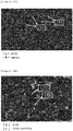
- FIG. 3A is a view illustrating an EDS mapping image for pores of a negative electrode cross-sectional sample obtained by using an energy-dispersive X-ray spectroscopy (EDS) according to an exemplary embodiment of the present invention
- FIG. 3B is a view illustrating an image extracted by applying the EDS mapping image for the pores of the negative electrode cross-sectional sample to image processing.
- EDS energy-dispersive X-ray spectroscopy
- the constituent materials of the negative electrode for a secondary battery expressed as a dark color and the pores expressed as a brighter color are clearly distinguished from each other.
- FIG. 3B it is possible to classify the image of the cross section of the negative electrode cross-sectional sample extracted by the image processing into the upper, middle, and lower regions. In addition, it is possible to classify the image into a total of nine unit regions by equally dividing each region, which is classified into the upper, middle, and lower regions, into three parts in a vertical direction and to quantitatively analyze the pores of the negative electrode for a secondary battery by using the same.
- the method may further include staining the binder before the producing of the electrode cross-sectional sample.
- the staining of the binder may be carried out before the filling of the pores of the electrode for a secondary battery with the polymer including silicon, and may also be carried out after the filling of the pores of the electrode for a secondary battery with the polymer including silicon. Even when the electrode cross-sectional sample is observed with a scanning electron microscope, it is possible to distinguish the binder, the electrode active material, the pores, and the like from one another by staining the binder.
- the binder, the electrode active material, the pores, and the like can be clearly distinguished from one another, thereby more precisely analyzing the pores of the electrode for a secondary battery.
- the staining of the binder may include staining the binder with a staining material including at least one of an osmium compound and a ruthenium compound.
- a staining material including at least one of an osmium compound and a ruthenium compound.
- an osmium oxide such as OsO 4 may be used as the osmium compound
- a ruthenium oxide such as RuO 4 may be used as the ruthenium compound.
- OsO 4 may react with and be bound to a double bond of butadiene as in the following Reaction Formula 1.
- An osmium component included in the osmium compound may maximize the contrast effect caused by the difference in atomic number, thereby clearly distinguishing the binder, the pores, the electrode active material, and the like of the electrode for a secondary battery from one another.
- the method may further include: detecting a staining material in the binder by using an energy-dispersive X-ray spectroscopy; and calculating an area ratio of the binder by analyzing an image in which points of the staining material detected by the energy-dispersive X-ray spectroscopy are mapped.
- the staining material when OsO 4 is used as the staining material, it is possible to detect osmium stained by staining the binder by using the energy-dispersive X-ray spectroscopy, and to extract an EDS mapping image in which points of the detected osmium are marked. Through the image in which the points of osmium are mapped, it is possible to grasp the area, position, distribution, and the like of the binder included in the electrode for a secondary battery. Accordingly, it is possible to more exactly confirm the distribution, size, number, position, and the like of pores present in the electrode for a secondary battery.
- the calculating of the area ratio of the binder by analyzing the image in which the points of the staining material detected by the energy-dispersive X-ray spectroscopy are mapped may include quantitatively analyzing an area of the binder at each portion of the electrode for a secondary battery by applying the EDS mapping image extracted by the energy-dispersive X-ray spectroscopy to image processing. Further, it is possible to classify the cross section of the electrode cross-sectional sample produced from the electrode for a secondary battery into the upper portion, the middle portion, and the lower portion, and to precisely calculate the area ratio of the binder by classifying each of the upper portion, the middle portion, and the lower portion into smaller unit regions.
- FIG. 4A is a view illustrating an EDS mapping image for a binder of the negative electrode cross-sectional sample obtained by using the EDS according to an exemplary embodiment of the present invention
- FIG. 4B is a view illustrating an image extracted by applying the EDS mapping image for the binder of the negative electrode cross-sectional sample to image processing.
- the constituent materials of the negative electrode for a secondary battery expressed as a dark color and the binder expressed as a brighter color are clearly distinguished from each other.
- FIG. 4B it is possible to classify the image of the cross section of the negative electrode cross-sectional sample extracted by the image processing into the upper, middle, and lower regions.
- the area ratio of the binder of the electrode for a secondary battery may be quantitatively analyzed by using a mapping image extracted by the energy-dispersive X-ray spectroscopy. Accordingly, the distribution of pores of the electrode for a secondary battery can be more exactly grasped, and the performance of the electrode for a secondary battery and a secondary battery including the same can be calculated in advance.
- the method for measuring a distribution of pores of an electrode for a secondary battery may be applied to a positive electrode and a negative electrode for a secondary battery.
- a negative electrode for a secondary battery (manufactured by LG CHEM) was prepared, and OsO 4 as a staining material and polydimethylsiloxane (PDMS) as a polymer including silicon were prepared.
- the binder of the negative electrode for a secondary battery was stained by using the prepared OsO 4 , and pores of the negative electrode for a secondary battery were filled with the PDMS by impregnating the negative electrode for a secondary battery into the prepared PDMS.
- the surface of the negative electrode for a secondary battery was trimmed by irradiating the negative electrode for a secondary battery with focused argon (Ar) ion beam using an ion milling device (IM 4000, manufactured by Hitachi, Ltd.) irradiating an argon ion beam, thereby producing a negative electrode cross-sectional sample having a clean cross section.
- the irradiation with argon ion beam was carried out by setting a discharge current and an ion beam current to 400 ⁇ A and 130 ⁇ A, respectively, and was carried out at a gas flow of 1 cm 3 /min for 3 hours.
- a negative electrode for a secondary battery which is the same as that in Example 1, was prepared, and a negative electrode cross-sectional sample was produced in the same manner as in Example 1, except that pores of the negative electrode for a secondary battery were filled with polydimethylsiloxane in a state where a binder of the negative electrode for a secondary battery was not stained.
- a negative electrode for a secondary battery which is the same as that in Example 1, was prepared, and a negative electrode cross-sectional sample was produced in the same manner as in Example 1, except that a binder of the negative electrode for a secondary battery was stained with OsO 4 , and pores of the negative electrode for a secondary battery were filled with a polymer including epoxy.
- a negative electrode for a secondary battery which is the same as that in Example 1, was prepared, and a negative electrode cross-sectional sample was produced in the same manner as in Example 1, except that a binder of the negative electrode for a secondary battery was not stained, and pores of the negative electrode for a secondary battery were not filled with a polymer including silicon.
- a negative electrode for a secondary battery which is the same as that in Example 1, was prepared, and a negative electrode cross-sectional sample was produced in the same manner as in Example 1, except that a binder of the negative electrode for a secondary battery was not stained, and pores of the negative electrode for a secondary battery were filled with a polymer including epoxy.
- the negative electrode cross-sectional samples produced in Examples 1 and 2 and Comparative Examples 1 to 3 of the present invention were observed with a scanning electron microscope (SU8020, manufactured by Hitachi, Ltd.), and the SEM photographs thereof were captured.
- FIG. 5A is a scanning electron microscope (SEM) photograph of the negative electrode cross-sectional sample produced in Example 1
- FIG. 5B is a SEM photograph of the negative electrode cross-sectional sample produced in Example 2
- FIG. 5C is a SEM photograph of the negative electrode cross-sectional sample produced in Comparative Example 1
- FIG. 5D is a SEM photograph of the negative electrode cross-sectional sample produced in Comparative Example 2
- FIG. 5E is a SEM photograph of the negative electrode cross-sectional sample produced in Comparative Example 3.
- the negative electrode constituent materials for a secondary battery such as an active material present on different focal planes at the bottom of the pore, were not observed because the pores of the negative electrodes for a secondary battery according to Examples 1 and 2 were impregnated into the PDMS, and as a result, the negative electrode constituent materials for a secondary battery and pores were clearly distinguished from each other.
- FIG. 5A it could be seen that in the case of Example 1 in which the binder of the negative electrode for a secondary battery was stained by using OsO 4 , the negative electrode constituent materials for a secondary battery, the binder, and the pores were clearly distinguished from one another, and as a result, the pores could be more exactly confirmed.
- the present invention it is possible to clearly distinguish pores and negative electrode constituent materials from each other by filling the pores of the electrode for a secondary battery with a polymer including silicon, and to clearly distinguish a binder of the electrode for a secondary battery by staining the binder, thereby more precisely confirming the pores of the electrode for a secondary battery.
- an energy-dispersive X-ray spectroscopy having an energy resolution of 5.9 keV or more and 136 keV or less and a minimum detection limit of 0.1 wt% was used.
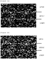
- FIG. 6A is a set of views illustrating the EDS mapping images of the negative electrode cross-sectional samples according to Examples 1 and 2 obtained by using the EDS
- FIG. 6B illustrates images extracted by applying the EDS mapping images for the negative electrode cross-sectional samples according to Examples 1 and 2 to image processing.
- the images of the cross section of the negative electrode cross-sectional sample extracted by the image processing can be classified into the upper, middle, and lower regions, and the image was classified into a total of nine unit regions by dividing each region, which was classified into the upper, middle, and lower regions, into three parts in a vertical direction, thereby quantitatively analyzing pores of a negative electrode for a secondary battery.
- Table 1 describes a porosity exhibiting the distribution of pores present in each area of the 9 unit regions of the negative electrode for a secondary battery produced in Example 1 and the ratio of the negative electrode active material and the binder region
- Table 2 describes the porosity of each area of the 9 unit regions of the negative electrode for a secondary battery produced in Example 2.
- Example 1 the distribution of pores of the negative electrode for a secondary battery could be more exactly confirmed in Example 1 in which the pores were impregnated into the PDMS and the binder was stained with OsO 4 , as compared to Example 2 in which the binder was not stained. Specifically, it could be confirmed that in the case of Example 1 in which the binder was stained, the pores and the negative electrode active material were distinguished from the binder, and as a result, the porosity in a unit region was smaller than that in Example 2, and accordingly, it could be seen that the porosity of the negative electrode for a secondary battery could be more exactly confirmed.
- the present invention it is possible to quantitatively analyze the pores, the active material, and the binder present in the electrode for a secondary battery, thereby predicting the performance of a secondary battery in which an electrode for a secondary battery is used.
Landscapes
- Chemical & Material Sciences (AREA)
- Health & Medical Sciences (AREA)
- Life Sciences & Earth Sciences (AREA)
- Physics & Mathematics (AREA)
- Analytical Chemistry (AREA)
- Biochemistry (AREA)
- General Health & Medical Sciences (AREA)
- General Physics & Mathematics (AREA)
- Immunology (AREA)
- Pathology (AREA)
- Engineering & Computer Science (AREA)
- Chemical Kinetics & Catalysis (AREA)
- Electrochemistry (AREA)
- General Chemical & Material Sciences (AREA)
- Dispersion Chemistry (AREA)
- Biomedical Technology (AREA)
- Molecular Biology (AREA)
- Materials Engineering (AREA)
- Spectroscopy & Molecular Physics (AREA)
- Crystallography & Structural Chemistry (AREA)
- Battery Electrode And Active Subsutance (AREA)
- Analysing Materials By The Use Of Radiation (AREA)
- Sampling And Sample Adjustment (AREA)
Abstract
Description
- This application claims priority to and the benefit of Korean Patent Application No.
10-2017-0065845 - The present invention relates to a method for measuring a distribution of pores in an electrode for a secondary battery, which can easily measure a distribution of pores inside the electrode for a secondary battery.
- A secondary battery is largely composed of electrodes, a separator, and an electrolytic solution, and the electrodes are classified into a negative electrode and a positive electrode. Since constituent materials such as an active material, a conductive material, and a binder are three-dimensionally distributed in the electrodes, a plurality of pores is present in gaps therebetween. The pores present in the electrodes are filled with an electrolytic solution in the secondary battery, and thus become channels for ions, and the like. Accordingly, since the size, number, distribution, and the like of pores affect the diffusivity of ions and significantly affect the performance of a secondary battery, it is important to exactly analyze the distribution of pores inside the electrode.
- However, it was difficult to observe the distribution of pores on the cross-section of the electrode in the related art, and since a scanning electron microscope (SEM) has a deep focal depth, signals from constituent materials inside the electrode, which are present on different focal planes at the bottom of the pore, are simultaneously detected, and as a result, there is a problem in that the actual pores are expressed as constituent materials inside the electrode on a scanning electron microscope image, thereby making it impossible to exactly analyzing the distribution of pores inside the electrode.
- Therefore, there is a need for a method which can clearly distinguish constituent materials and pores inside the electrode from each other and simultaneously analyze the distribution of pores inside the electrode.
- (Patent Document 1) Korean Patent Application Laid-Open No.
2014-0132956 - The present invention has been made in an effort to provide a method for measuring a distribution of pores in an electrode for a secondary battery, which can easily analyze a distribution of pores inside the electrode by clearly distinguishing the constituent materials and pores inside the electrode from each other.
- However, a problem to be solved by the present invention is not limited to the aforementioned problem, and the other problems that are not mentioned may be clearly understood by a person skilled in the art from the following description.
- An exemplary embodiment of the present invention provides a method for measuring a distribution of pores in an electrode for a secondary battery, the method including: preparing an electrode for a secondary battery including an electrode active material, a binder, and a conductive material; filling pores inside the electrode for a secondary battery with a polymer including silicon by impregnating the polymer including silicon into the electrode for a secondary battery; producing an electrode cross-sectional sample by irradiating the electrode for a secondary battery with an ion beam of an ion milling device; detecting silicon present on the electrode cross-sectional sample by using an energy-dispersive X-ray spectroscopy; and confirming a distribution of pores by analyzing an image in which points of silicon detected by the energy-dispersive X-ray spectroscopy are mapped.
- A method for measuring a distribution of pores in an electrode for a secondary battery according to an exemplary embodiment of the present invention can confirm a distribution of pores inside the electrode by clearly distinguishing the constituent materials of the electrode from each other, thereby exactly predicting the performance of the electrode for a secondary battery.
- According to an exemplary embodiment of the present invention, pores in the electrode can be more exactly distinguished by staining a binder.
- The effects of the present invention are not limited to the above-described effects, and effects, which are not mentioned, will be clearly understood by a person skilled in the art from the specification of the present application and the accompanying drawings.
-
-
FIG. 1 is a view illustrating an ion milling device used in the producing of the electrode cross-sectional sample according to an exemplary embodiment of the present invention. -
FIG. 2A is a set of views illustrating cross-sections of two negative electrodes for a secondary battery, andFIG. 2B is a graph illustrating charge characteristics of the two negative electrodes for a secondary battery. -
FIG. 3A is a view illustrating an EDS mapping image for pores of a negative electrode cross-sectional sample obtained by using an energy-dispersive X-ray spectroscopy (EDS) according to an exemplary embodiment of the present invention, andFIG. 3B is a view illustrating an image extracted by applying the EDS mapping image for the pores of the negative electrode cross-sectional sample to image processing. -
FIG. 4A is a view illustrating an EDS mapping image for a binder of the negative electrode cross-sectional sample obtained by using the EDS according to an exemplary embodiment of the present invention, andFIG. 4B is a view illustrating an image extracted by applying the EDS mapping image for the binder of the negative electrode cross-sectional sample to image processing. -
FIG. 5A is a scanning electron microscope (SEM) photograph of a negative electrode cross-sectional sample produced in Example 1,FIG. 5B is a SEM photograph of a negative electrode cross-sectional sample produced in Example 2,FIG. 5C is a SEM photograph of a negative electrode cross-sectional sample produced in Comparative Example 1,FIG. 5D is a SEM photograph of a negative electrode cross-sectional sample produced in Comparative Example 2, andFIG. 5E is a SEM photograph of a negative electrode cross-sectional sample produced in Comparative Example 3. -
FIG. 6A is a set of views illustrating EDS mapping images of the negative electrode cross-sectional samples according to Examples 1 and 2 of the present invention obtained by using the EDS, andFIG. 6B illustrates images extracted by applying the EDS mapping images for the negative electrode cross-sectional samples according to Examples 1 and 2 to image processing. - When one part "includes" one constituent element throughout the specification of the present application, unless otherwise specifically described, this does not mean that another constituent element is excluded, but means that another constituent element may be further included.
- Throughout the specification of the present application, when one member is disposed "on" another member, this includes not only a case where the one member is brought into contact with another member, but also a case where still another member is present between the two members.
- Hereinafter, the present specification will be described in more detail.
- An exemplary embodiment of the present invention provides a method for measuring a distribution of pores in an electrode for a secondary battery, the method including: preparing an electrode for a secondary battery including an electrode active material, a binder, and a conductive material; filling pores inside the electrode for a secondary battery with a polymer including silicon by impregnating the polymer including silicon into the electrode for a secondary battery; producing an electrode cross-sectional sample by irradiating the electrode for a secondary battery with an ion beam of an ion milling device; detecting silicon present on the electrode cross-sectional sample by using an energy-dispersive X-ray spectroscopy; and confirming a distribution of pores by analyzing an image in which points of silicon detected by the energy-dispersive X-ray spectroscopy are mapped.
- A method for measuring a distribution of pores in an electrode for a secondary battery according to an exemplary embodiment of the present invention can confirm a distribution of pores inside the electrode by clearly distinguishing the constituent materials and pores of the electrode from each other, thereby exactly predicting the performance of the electrode for a secondary battery.
- According to an exemplary embodiment of the present invention, the electrode for a secondary battery includes an electrode active material, a binder, and a conductive material. Further, the electrode of a secondary battery may further include various additives capable of improving the performance thereof. The electrode active material, the binder, the conductive material, and the like are three-dimensionally distributed in an electrode for a secondary battery, and a plurality of pores may be present in gaps therebetween. That is, electrode constituent materials such as an electrode active material, a binder, and a conductive material and a plurality of pores may constitute the electrode for a secondary battery.
- As the electrode active material, the binder, the conductive material, and the like, which are included in the electrode for a secondary battery, materials typically used in the art may be adopted and used without any particular limitation. Specifically, when the electrode for a secondary battery is a negative electrode, it is possible to use, as the binder, carboxymethyl cellulose (CMC), a diene-based binder such as butadiene, an acrylic binder, and the like. Furthermore, as the negative electrode active material, it is possible to use a carbon-based material in various forms, including artificial graphite, natural graphite, or hard carbon capable of intercalating and deintercalating lithium, a non-carbon-based material including silicon (Si), lithium titanium oxide (LTO), and the like.
- According to an exemplary embodiment of the present invention, the filling of pores inside the electrode for a secondary battery with the polymer including silicon may be penetrating the polymer including silicon into the electrode for a secondary battery by impregnating the polymer including silicon into the electrode for a secondary battery. As the polymer including silicon, a liquid-phase polymer may be used. By using a liquid-phase polymer including silicon, it is possible to more effectively fill pores of the electrode for a secondary battery with the polymer including silicon. A method of impregnating the polymer including silicon into the pores of the electrode for a secondary battery may be carried out by a typical method in the art. For example, the polymer including silicon may be impregnated into the pores of the electrode for a secondary battery by a method of applying the polymer including silicon onto the electrode for a secondary battery, immersing the electrode for a secondary battery into a polymer solution including silicon, or the like.
-
FIG. 1 is a view illustrating an ion milling device used in the producing of the electrode cross-sectional sample according to an exemplary embodiment of the present invention. Referring toFIG. 1 , a focused ion beam produced from an ion gun may pass through a mask, and then the surface of the sample may be irradiated with the focused ion beam. - According to an exemplary embodiment of the present invention, electrode materials may be sputtered by irradiating the electrode for a secondary battery with an ion beam produced from an ion gun of an ion milling device. Accordingly, it is possible to produce an electrode cross-sectional sample having a clean cross section which is not physically damaged. As the electrode cross-sectional sample has a clean cross section which is not physically damaged, the pores of the electrode for a secondary battery can be more precisely analyzed.
- According to an exemplary embodiment of the present invention, the ion beam may be an argon ion beam. The electrode cross-sectional sample may be more stably produced by irradiating the electrode for a secondary battery with an argon ion beam.
- According to an exemplary embodiment of the present invention, an ion beam current of the ion milling device may be 100 µA or more and 250 µA or less. Specifically, the ion beam current of the ion milling device may be 110 µA or more and 150 µA or less, or 200 µA or more and 230 µA or less. By adjusting the ion beam current of the ion milling device to the above-described range, it is possible to shorten the time taken to produce the electrode cross-sectional sample and to prevent a phenomenon in which electrode materials are redeposited onto the cross section of the sample, thereby producing an electrode cross-sectional sample having a cleaner cross section. Accordingly, it is possible to increase the efficiency of analyzing pores inside the electrode for a secondary battery.
- According to an exemplary embodiment of the present invention, a discharge current of the ion milling device may be 250 µA or more and 450 µA or less. Specifically, the discharge current of the ion milling device may be 370 µA or more and 450 µA or less, or 400 µA or more and 430 µA or less. By adjusting the discharge current of the ion milling device to the above-described range, it is possible to prevent the operation efficiency of the ion milling device from being decreased and to minimize the time taken to produce the electrode cross-sectional sample.
- According to an exemplary embodiment of the present invention, in the detecting of silicon present in the electrode cross-sectional sample, a point where silicon is present in the electrode cross-sectional sample can be grasped by using the energy-dispersive X-ray spectroscopy. Specifically, the pores of the electrode for a secondary battery are filled with the polymer including silicon, and it is possible to detect silicon included in the polymer filling the pores by using the energy-dispersive X-ray spectroscopy. Accordingly, it is possible to grasp a point where pores are located in the electrode for a secondary battery, and the size, number, distribution, and the like of the pores.
- Since pores formed in gaps among the materials constituting the electrode may become channels for ions, and the like, the size, number, distribution, and the like of the pores present in the electrode may significantly affect the secondary battery performance.
-
FIG. 2A is a set of views of cross-sections of two negative electrodes for a secondary battery, andFIG. 2B is a graph illustrating charge characteristics of the two negative electrodes for a secondary battery. Specifically,FIG. 2A illustrates the cross sections of the two negative electrodes for a secondary battery, which have the same distribution of total pores, but the different distributions of pores at the upper portion and lower portion on the cross-section of each of the negative electrodes for a secondary battery. -
Negative Electrode 1 andNegative Electrode 2 have the same distribution of total pores of 25% on the same area. However, referring toFIG. 2A , in the case ofNegative Electrode 1, the pores having similar sizes are uniformly distributed at the upper portion and the lower portion on the cross section of the negative electrode. In contrast, in the case ofNegative Electrode 2, the pores present at the upper portion on the cross section of the negative electrode are larger than those present at the lower portion, and a larger number of pores are present at the upper portion than at the lower portion.FIG. 2B is a graph illustrating charge characteristics (state of charge; SOC) according to the voltage applied toNegative Electrode 1 andNegative Electrode 2. Referring toFIG. 2B , it can be seen thatNegative Electrode 2, in which the pores present at the upper portion on the cross section of the negative electrode are larger than those at the lower portion and a larger number of pores are present at the upper portion than at the lower portion, has better charge characteristics than those ofNegative Electrode 1, in which the pores having similar sizes are uniformly distributed at the upper portion and the lower portion on the cross section of the negative electrode. - Accordingly, when the size, number, distribution, and the like of pores inside the electrode are exactly analyzed, it is possible to more effectively predict the performance of an electrode for a secondary battery and a secondary battery including the same.
- In the related art, a scanning electron microscope (SEM) was used in order to analyze the size, number, distribution, and the like of pores present in an electrode for a secondary battery. However, since the scanning electron microscope (SEM) has a deep focal depth, there is a problem in that signals from an electrode active material, a binder, and the like of an electrode for a secondary battery, which are present on different focal planes at the bottom of the pore, are simultaneously detected. Thus, the pores are expressed, in spite of the pores present in an electrode for a secondary battery, as constituent materials of the electrode for a secondary battery on an image produced by a scanning electron microscope, thereby making it impossible to exactly analyze the pores present in the electrode for a secondary battery.
- In contrast, according to an exemplary embodiment of the present invention, by filling the pores of the electrode for a secondary battery with a polymer including silicon and detecting silicon present in the electrode cross-sectional sample produced from the electrode for a secondary battery, the constituent materials and pores of the electrode for a secondary battery can be clearly distinguished from each other, and the size, number, distribution, and the like of the pores can be easily confirmed.
- Specifically, by filling the pores of the electrode for a secondary battery with the polymer including silicon, it is possible to prevent a phenomenon of simultaneously detecting signals from the constituent materials of the electrode for a secondary battery, which may be generated as the constituent materials of the electrode for a secondary battery are present on the different focal planes at the bottom of the pore. Accordingly, even when an electrode cross-sectional sample in which the pores of the electrode for a secondary battery are filled with the polymer including silicon is observed with a scanning electron microscope, it is possible to distinguish the pores from the constituent materials of the electrode for a secondary battery. Further, silicon of the polymer filling the pores of the electrode for a secondary battery is detected by using an energy-dispersive X-ray spectroscopy, thereby clearly distinguishing the constituent materials and pores of the electrode for a secondary battery from each other to easily analyze the size, number, distribution, and the like of the pores.
- Accordingly, according to an exemplary embodiment of the present invention, by clearly distinguishing the constituent materials and pores of the electrode for a secondary battery from each other, the pores can be exactly analyzed and the distribution of the pores can be confirmed, thereby more effectively predicting the performance of the electrode for a secondary battery and a secondary battery including the same.
- According to an exemplary embodiment of the present invention, the polymer including silicon may include one or more selected from the group consisting of polydimethylsiloxane, polysiloxane, polysilane, and polysilazane. Silicon may be included in a repeat unit of the polymer including silicon. A silicon component included in the polymer may maximize the contrast effect caused by the difference in atomic number, thereby clearly distinguishing the pores and constituent materials of the electrode for a secondary battery from each other.
- According to an exemplary embodiment of the present invention, it is possible to confirm the distribution, size, number, position, and the like of pores present in the electrode for a secondary battery by analyzing an image in which the points of silicon detected by the energy-dispersive X-ray spectroscopy are mapped.
- As the energy-dispersive X-ray spectroscopy (EDS), one attached to a scanning electron microscope may be used. The energy-dispersive X-ray spectroscopy is an analyzing apparatus of measuring components of a sample by detecting X-ray generated when the surface of the sample is irradiated with an electron beam, and has advantages in that the apparatus is simply operated and can simultaneously detect energies of all the elements included in the sample.
- According to an exemplary embodiment of the present invention, as the energy-dispersive X-ray spectroscopy, it is possible to use an apparatus having an energy resolution of 5.9 keV or more and 136 keV or less and a minimum detection limit of 0.1 wt%. By using an energy-dispersive X-ray spectroscopy having the conditions, it is possible to more exactly detect silicon of the polymer filling the pores of the electrode for a secondary battery.
- According to an exemplary embodiment of the present invention, by using the energy-dispersive X-ray spectroscopy, it is possible to detect silicon of the polymer filling the pores of the electrode for a secondary battery and to extract an EDS mapping image in which the positions of the detected silicon are marked. Through the image in which the positions of silicon are mapped, it is possible to confirm the position, shape, size, number, distribution, and the like of the pores of the electrode for a secondary battery.
- According to an exemplary embodiment of the present invention, the confirming of the distribution of pores may include quantitatively analyzing the distribution of pores of the electrode for a secondary battery. Specifically, the distribution of pores at each portion of the electrode for a secondary battery can be quantitatively analyzed by applying an EDS mapping image extracted by the energy-dispersive X-ray spectroscopy to image processing. For example, by converting the EDS mapping image into black and white through the image processing and using the difference in brightness at each portion in the EDS mapping image converted into black and white, it is possible to effectively distinguish the pores and electrode constituent materials, which are shown on the cross section of the electrode cross-sectional sample, from each other. The distribution of pores at each portion of the electrode for a secondary battery can be quantitatively analyzed by distinguishing the pores and electrode constituent materials of the electrode cross-sectional sample from each other.
- It is possible to classify the cross section of the electrode cross-sectional sample produced from the electrode for a secondary battery into the upper portion, the middle portion, and the lower portion, and to quantitatively analyze the distribution of pores with precision by classifying each of the upper portion, the middle portion, and the lower portion into smaller unit regions.
- Accordingly, according to an exemplary embodiment of the present invention, the distribution of the pores of the electrode for a secondary battery can be quantitatively analyzed by using a mapping image extracted by the energy-dispersive X-ray spectroscopy, thereby calculating the performance of a secondary battery including the electrode for a secondary battery in advance.
-
FIG. 3A is a view illustrating an EDS mapping image for pores of a negative electrode cross-sectional sample obtained by using an energy-dispersive X-ray spectroscopy (EDS) according to an exemplary embodiment of the present invention, andFIG. 3B is a view illustrating an image extracted by applying the EDS mapping image for the pores of the negative electrode cross-sectional sample to image processing. - Referring to
FIG. 3A , it can be confirmed that on the EDS mapping image in which the points of silicon detected by the energy-dispersive X-ray spectroscopy are marked, the constituent materials of the negative electrode for a secondary battery expressed as a dark color and the pores expressed as a brighter color are clearly distinguished from each other. As inFIG. 3B , it is possible to classify the image of the cross section of the negative electrode cross-sectional sample extracted by the image processing into the upper, middle, and lower regions. In addition, it is possible to classify the image into a total of nine unit regions by equally dividing each region, which is classified into the upper, middle, and lower regions, into three parts in a vertical direction and to quantitatively analyze the pores of the negative electrode for a secondary battery by using the same. - According to an exemplary embodiment of the present invention, the method may further include staining the binder before the producing of the electrode cross-sectional sample. The staining of the binder may be carried out before the filling of the pores of the electrode for a secondary battery with the polymer including silicon, and may also be carried out after the filling of the pores of the electrode for a secondary battery with the polymer including silicon. Even when the electrode cross-sectional sample is observed with a scanning electron microscope, it is possible to distinguish the binder, the electrode active material, the pores, and the like from one another by staining the binder.
- Accordingly, according to an exemplary embodiment of the present invention, by staining a binder included in the electrode for a secondary battery, the binder, the electrode active material, the pores, and the like can be clearly distinguished from one another, thereby more precisely analyzing the pores of the electrode for a secondary battery.
- According to an exemplary embodiment of the present invention, the staining of the binder may include staining the binder with a staining material including at least one of an osmium compound and a ruthenium compound. As an example, an osmium oxide such as OsO4 may be used as the osmium compound, and a ruthenium oxide such as RuO4 may be used as the ruthenium compound. Specifically, when diene-based butadiene is used as a binder included in the electrode for a secondary battery and OsO4 is used as a staining material, OsO4 may react with and be bound to a double bond of butadiene as in the following
Reaction Formula 1.
- An osmium component included in the osmium compound may maximize the contrast effect caused by the difference in atomic number, thereby clearly distinguishing the binder, the pores, the electrode active material, and the like of the electrode for a secondary battery from one another.
- According to an exemplary embodiment of the present invention, the method may further include: detecting a staining material in the binder by using an energy-dispersive X-ray spectroscopy; and calculating an area ratio of the binder by analyzing an image in which points of the staining material detected by the energy-dispersive X-ray spectroscopy are mapped.
- Hereinafter, a case where OsO4 is used as a staining material will be described in detail.
- According to an exemplary embodiment of the present invention, when OsO4 is used as the staining material, it is possible to detect osmium stained by staining the binder by using the energy-dispersive X-ray spectroscopy, and to extract an EDS mapping image in which points of the detected osmium are marked. Through the image in which the points of osmium are mapped, it is possible to grasp the area, position, distribution, and the like of the binder included in the electrode for a secondary battery. Accordingly, it is possible to more exactly confirm the distribution, size, number, position, and the like of pores present in the electrode for a secondary battery.
- According to an exemplary embodiment of the present invention, the calculating of the area ratio of the binder by analyzing the image in which the points of the staining material detected by the energy-dispersive X-ray spectroscopy are mapped may include quantitatively analyzing an area of the binder at each portion of the electrode for a secondary battery by applying the EDS mapping image extracted by the energy-dispersive X-ray spectroscopy to image processing. Further, it is possible to classify the cross section of the electrode cross-sectional sample produced from the electrode for a secondary battery into the upper portion, the middle portion, and the lower portion, and to precisely calculate the area ratio of the binder by classifying each of the upper portion, the middle portion, and the lower portion into smaller unit regions.
-
FIG. 4A is a view illustrating an EDS mapping image for a binder of the negative electrode cross-sectional sample obtained by using the EDS according to an exemplary embodiment of the present invention, andFIG. 4B is a view illustrating an image extracted by applying the EDS mapping image for the binder of the negative electrode cross-sectional sample to image processing. - Referring to
FIG. 4A , it can be confirmed that on the EDS mapping image in which the points of osmium detected by the energy-dispersive X-ray spectroscopy are marked, the constituent materials of the negative electrode for a secondary battery expressed as a dark color and the binder expressed as a brighter color are clearly distinguished from each other. As illustrated inFIG. 4B , it is possible to classify the image of the cross section of the negative electrode cross-sectional sample extracted by the image processing into the upper, middle, and lower regions. In addition, it is possible to classify the image into a total of nine unit regions by dividing each region, which is classified into the upper, middle, and lower regions, into three parts in a vertical direction and to quantitatively analyze the area of the binder of the negative electrode for a secondary battery by using the same. - Accordingly, according to an exemplary embodiment of the present invention, the area ratio of the binder of the electrode for a secondary battery may be quantitatively analyzed by using a mapping image extracted by the energy-dispersive X-ray spectroscopy. Accordingly, the distribution of pores of the electrode for a secondary battery can be more exactly grasped, and the performance of the electrode for a secondary battery and a secondary battery including the same can be calculated in advance.
- The method for measuring a distribution of pores of an electrode for a secondary battery according to an exemplary embodiment of the present invention may be applied to a positive electrode and a negative electrode for a secondary battery.
- Hereinafter, the present invention will be described in more detail through Examples. The following Examples relate to a negative electrode of the electrodes for a secondary battery, and these Examples are provided only for illustrative purposes, and are not intended to limit the scope of the present invention.
- A negative electrode for a secondary battery (manufactured by LG CHEM) was prepared, and OsO4 as a staining material and polydimethylsiloxane (PDMS) as a polymer including silicon were prepared. The binder of the negative electrode for a secondary battery was stained by using the prepared OsO4, and pores of the negative electrode for a secondary battery were filled with the PDMS by impregnating the negative electrode for a secondary battery into the prepared PDMS. Thereafter, the surface of the negative electrode for a secondary battery was trimmed by irradiating the negative electrode for a secondary battery with focused argon (Ar) ion beam using an ion milling device (IM 4000, manufactured by Hitachi, Ltd.) irradiating an argon ion beam, thereby producing a negative electrode cross-sectional sample having a clean cross section. The irradiation with argon ion beam was carried out by setting a discharge current and an ion beam current to 400 µA and 130 µA, respectively, and was carried out at a gas flow of 1 cm3/min for 3 hours.
- A negative electrode for a secondary battery, which is the same as that in Example 1, was prepared, and a negative electrode cross-sectional sample was produced in the same manner as in Example 1, except that pores of the negative electrode for a secondary battery were filled with polydimethylsiloxane in a state where a binder of the negative electrode for a secondary battery was not stained.
- A negative electrode for a secondary battery, which is the same as that in Example 1, was prepared, and a negative electrode cross-sectional sample was produced in the same manner as in Example 1, except that a binder of the negative electrode for a secondary battery was stained with OsO4, and pores of the negative electrode for a secondary battery were filled with a polymer including epoxy.
- A negative electrode for a secondary battery, which is the same as that in Example 1, was prepared, and a negative electrode cross-sectional sample was produced in the same manner as in Example 1, except that a binder of the negative electrode for a secondary battery was not stained, and pores of the negative electrode for a secondary battery were not filled with a polymer including silicon.
- A negative electrode for a secondary battery, which is the same as that in Example 1, was prepared, and a negative electrode cross-sectional sample was produced in the same manner as in Example 1, except that a binder of the negative electrode for a secondary battery was not stained, and pores of the negative electrode for a secondary battery were filled with a polymer including epoxy.
- The negative electrode cross-sectional samples produced in Examples 1 and 2 and Comparative Examples 1 to 3 of the present invention were observed with a scanning electron microscope (SU8020, manufactured by Hitachi, Ltd.), and the SEM photographs thereof were captured.
-
FIG. 5A is a scanning electron microscope (SEM) photograph of the negative electrode cross-sectional sample produced in Example 1,FIG. 5B is a SEM photograph of the negative electrode cross-sectional sample produced in Example 2,FIG. 5C is a SEM photograph of the negative electrode cross-sectional sample produced in Comparative Example 1,FIG. 5D is a SEM photograph of the negative electrode cross-sectional sample produced in Comparative Example 2, andFIG. 5E is a SEM photograph of the negative electrode cross-sectional sample produced in Comparative Example 3. - Referring to
FIGS. 5A and 5B , it was confirmed that the negative electrode constituent materials for a secondary battery, such as an active material present on different focal planes at the bottom of the pore, were not observed because the pores of the negative electrodes for a secondary battery according to Examples 1 and 2 were impregnated into the PDMS, and as a result, the negative electrode constituent materials for a secondary battery and pores were clearly distinguished from each other. Furthermore, referring toFIG. 5A , it could be seen that in the case of Example 1 in which the binder of the negative electrode for a secondary battery was stained by using OsO4, the negative electrode constituent materials for a secondary battery, the binder, and the pores were clearly distinguished from one another, and as a result, the pores could be more exactly confirmed. - In contrast, referring to
FIG. 5D , it was confirmed that in the case of Comparative Example 2 in which the pores of the negative electrode for a secondary battery were not impregnated with a polymer including silicon, the negative electrode constituent materials for a secondary battery, such as an active material present on different focal planes at the bottom of the pore, were together observed by a deep focal depth of a scanning electron microscope, and as a result, it was difficult to distinguish the negative electrode constituent materials for a secondary battery and the pores from each other. Further, it was confirmed that in the case of Comparative Example 2, the binder was not stained, and as a result, it was difficult to distinguish the negative electrode constituent materials, the pores, and the binder from one another. - Referring to
FIGS. 5C and5E , it could be confirmed that in the case of Comparative Examples 1 and 3 in which the pores of the negative electrode for a secondary battery were filled with a polymer including epoxy, the pores and the negative electrode active material were not easily distinguished from each other, as compared to Examples 1 and 2 in which the pores were impregnated into the PDMS. Furthermore, by the difference, it can be seen that when the SEM photographs of Examples 1 and 2 and Comparative Examples 1 and 3 are applied to image processing, the pores and the negative electrode active material can be more clearly distinguished from each other as compared to Examples 1 and 2. - Accordingly, according to an exemplary embodiment of the present invention, it is possible to clearly distinguish pores and negative electrode constituent materials from each other by filling the pores of the electrode for a secondary battery with a polymer including silicon, and to clearly distinguish a binder of the electrode for a secondary battery by staining the binder, thereby more precisely confirming the pores of the electrode for a secondary battery.
- From the negative electrode cross-sectional sample produced in Example 1, silicon components of the PDMS filling the pores of the negative electrode for a secondary battery were detected and osmium components of an OsO4 staining material staining the binder of the negative electrode for a secondary battery were detected, by using an energy-dispersive X-ray spectroscopy attached to a scanning electron microscope (SU8020, manufactured by Hitachi, Ltd.). Thereafter, EDS mapping images in which points of the detected silicon and osmium were marked were extracted. Thereafter, images for quantitatively analyzing pores were extracted by applying the extracted EDS mapping images to image processing. In this case, as the energy-dispersive X-ray spectroscopy, an energy-dispersive X-ray spectroscopy having an energy resolution of 5.9 keV or more and 136 keV or less and a minimum detection limit of 0.1 wt% was used.
- From the negative electrode cross-sectional sample produced in Example 2, silicon components of the PDMS filling the pores of the negative electrode for a secondary battery were detected and an EDS mapping image in which points of the detected silicon were marked was extracted, by using the energy-dispersive X-ray spectroscopy. Thereafter, an image for quantitatively analyzing pores was extracted by applying the extracted EDS mapping image to image processing.
-
FIG. 6A is a set of views illustrating the EDS mapping images of the negative electrode cross-sectional samples according to Examples 1 and 2 obtained by using the EDS, andFIG. 6B illustrates images extracted by applying the EDS mapping images for the negative electrode cross-sectional samples according to Examples 1 and 2 to image processing. - Referring to
FIG. 6A , it could be confirmed that in the case of Example 1, the pores, the negative electrode active material, and the binder were clearly distinguished from one another on the negative electrode cross-sectional sample, and it was confirmed that in the case of Example 2, the binder was not stained, and as a result, only the pores and the negative electrode active material could be distinguished from each other. Furthermore, as illustrated inFIG. 6B , the images of the cross section of the negative electrode cross-sectional sample extracted by the image processing can be classified into the upper, middle, and lower regions, and the image was classified into a total of nine unit regions by dividing each region, which was classified into the upper, middle, and lower regions, into three parts in a vertical direction, thereby quantitatively analyzing pores of a negative electrode for a secondary battery. - The following Table 1 describes a porosity exhibiting the distribution of pores present in each area of the 9 unit regions of the negative electrode for a secondary battery produced in Example 1 and the ratio of the negative electrode active material and the binder region, and the following Table 2 describes the porosity of each area of the 9 unit regions of the negative electrode for a secondary battery produced in Example 2.
[Table 1] Region Upper Middle Lower Average Unit region 1 2 3 4 5 6 7 8 9 Negative electrode active material (%) 65.1 59.6 57.2 61. 0 58.7 60.3 59.8 54.4 57.4 59.3 Binder (%) 0.7 2.1 2.0 2.5 1.7 3.1 1.1 1.4 1.3 1.8 Porosity (%) 34.2 38.3 40.8 36.5 39.6 36.6 39.1 44.2 41.3 38.9 [Table 2] Region Upper Middle Lower Average Unit region 1 2 3 4 5 6 7 8 9 Negative electrode active material (%) 65.7 58.8 56.4 61.3 57.3 60.7 60.8 54.6 57.2 59.2 Porosity (%) 34.3 41.2 43.6 38.7 42.7 39.3 39.2 45.4 42.8 40.8 - Referring to Tables 1 and 2, it could be seen that the distribution of pores of the negative electrode for a secondary battery could be more exactly confirmed in Example 1 in which the pores were impregnated into the PDMS and the binder was stained with OsO4, as compared to Example 2 in which the binder was not stained. Specifically, it could be confirmed that in the case of Example 1 in which the binder was stained, the pores and the negative electrode active material were distinguished from the binder, and as a result, the porosity in a unit region was smaller than that in Example 2, and accordingly, it could be seen that the porosity of the negative electrode for a secondary battery could be more exactly confirmed.
- Accordingly, according to an exemplary embodiment of the present invention, it is possible to quantitatively analyze the pores, the active material, and the binder present in the electrode for a secondary battery, thereby predicting the performance of a secondary battery in which an electrode for a secondary battery is used.
Claims (8)
- A method for measuring a distribution of pores in an electrode for a secondary battery, the method comprising:preparing an electrode for a secondary battery comprising an electrode active material, a binder, and a conductive material;filling pores inside the electrode for a secondary battery with a polymer comprising silicon by impregnating the polymer comprising silicon into the electrode for a secondary battery;producing an electrode cross-sectional sample by irradiating the electrode for a secondary battery with an ion beam of an ion milling device;detecting silicon present on the electrode cross-sectional sample by using an energy-dispersive X-ray spectroscopy; andconfirming a distribution of pores by analyzing an image in which points of silicon detected by the energy-dispersive X-ray spectroscopy are mapped.
- The method of claim 1, wherein the polymer comprising silicon comprises one or more selected from the group consisting of polydimethylsiloxane, polysiloxane, polysilane, and polysilazane.
- The method of claim 1, further comprising:
staining the binder, before the producing of the electrode cross-sectional sample. - The method of claim 3, wherein the staining of the binder comprises staining the binder with a staining material comprising at least one of an osmium compound and a ruthenium compound.
- The method of claim 4, further comprising:detecting the staining material in the binder by using an energy-dispersive X-ray spectroscopy; andcalculating an area ratio of the binder by analyzing an image in which points of the staining material detected by the energy-dispersive X-ray spectroscopy are mapped.
- The method of claim 1, wherein the ion beam is an argon ion beam.
- The method of claim 1, wherein an ion beam current of the ion milling device is 100 µA or more and 250 µA or less.
- The method of claim 1, wherein a discharge current of the ion milling device is 250 µA or more and 450 µA or less.
Applications Claiming Priority (2)
| Application Number | Priority Date | Filing Date | Title |
|---|---|---|---|
| KR20170065845 | 2017-05-29 | ||
| PCT/KR2018/006076 WO2018221929A1 (en) | 2017-05-29 | 2018-05-29 | Method for measuring pore distribution in electrode for secondary battery |
Publications (3)
| Publication Number | Publication Date |
|---|---|
| EP3633359A1 true EP3633359A1 (en) | 2020-04-08 |
| EP3633359A4 EP3633359A4 (en) | 2020-06-24 |
| EP3633359B1 EP3633359B1 (en) | 2024-06-12 |
Family
ID=64455067
Family Applications (1)
| Application Number | Title | Priority Date | Filing Date |
|---|---|---|---|
| EP18809590.5A Active EP3633359B1 (en) | 2017-05-29 | 2018-05-29 | Method for measuring pore distribution in electrode for secondary battery |
Country Status (8)
| Country | Link |
|---|---|
| US (1) | US12196651B2 (en) |
| EP (1) | EP3633359B1 (en) |
| JP (1) | JP6860129B2 (en) |
| KR (1) | KR102097613B1 (en) |
| CN (1) | CN110352347B (en) |
| ES (1) | ES2992774T3 (en) |
| HU (1) | HUE067672T2 (en) |
| WO (1) | WO2018221929A1 (en) |
Families Citing this family (8)
| Publication number | Priority date | Publication date | Assignee | Title |
|---|---|---|---|---|
| KR102420242B1 (en) | 2019-07-10 | 2022-07-13 | 주식회사 엘지에너지솔루션 | Analysing method for electrode active material crack rate of electrode for lithium secondary battery |
| KR102757591B1 (en) * | 2019-11-14 | 2025-01-21 | 주식회사 엘지화학 | Method of evaluation for dispersion of carbon material in the composite material |
| WO2021128092A1 (en) * | 2019-12-25 | 2021-07-01 | 宁德新能源科技有限公司 | Electrochemical device and electronic device containing same |
| KR102852673B1 (en) | 2020-09-29 | 2025-08-28 | 주식회사 엘지에너지솔루션 | Apparatus and method for predicting performance of secondary cell according to the electrode structure |
| KR102648343B1 (en) * | 2021-04-06 | 2024-03-14 | 주식회사 엘지에너지솔루션 | Method for prior detecting detective products of porous polymer substrate for separator |
| CN115979907B (en) * | 2021-10-14 | 2024-11-19 | 比亚迪股份有限公司 | Electrode slice and pore detection method thereof |
| US20260086051A1 (en) * | 2022-09-06 | 2026-03-26 | Lg Chem, Ltd. | Analysis Method of Pore Distribution of Porous Structures |
| KR102886424B1 (en) * | 2023-12-22 | 2025-11-17 | 에스케이이노베이션 주식회사 | Production of 3D shape structure of secondary battery separator and 3D pore shape analysis method using the same |
Family Cites Families (16)
| Publication number | Priority date | Publication date | Assignee | Title |
|---|---|---|---|---|
| JP3686952B2 (en) | 1998-12-08 | 2005-08-24 | 独立行政法人 国立印刷局 | Cross-sectional observation method for ink transfer products |
| JP2003139728A (en) | 2001-11-05 | 2003-05-14 | Toray Res Center:Kk | Method of analyzing structure of porous material, and photograph for structure analysis |
| JP3922064B2 (en) * | 2002-03-25 | 2007-05-30 | 松下電器産業株式会社 | Method for evaluating the dispersion state of the binder in the battery electrode plate |
| KR100766967B1 (en) | 2006-11-20 | 2007-10-15 | 삼성에스디아이 주식회사 | Electrode for lithium secondary battery, and lithium secondary battery manufactured therefrom |
| KR20070011543A (en) * | 2006-11-27 | 2007-01-24 | 니폰 쇼쿠바이 컴파니 리미티드 | Anode support substrate for solid oxide fuel cell and manufacturing method thereof |
| CN103493264A (en) | 2011-04-07 | 2014-01-01 | 古河电气工业株式会社 | Positive electrode active material, non-aqueous electrolyte secondary battery, and process for producing positive electrode active material |
| WO2013003846A2 (en) | 2011-06-30 | 2013-01-03 | The Regents Of The University Of California | Surface insulated porous current collectors as dendrite free electrodeposition electrodes |
| JP5675519B2 (en) * | 2011-07-11 | 2015-02-25 | 株式会社日立製作所 | Secondary battery negative electrode, non-aqueous electrolyte secondary battery using secondary battery negative electrode, and methods for producing the same |
| CN102735599B (en) | 2012-06-21 | 2016-12-21 | 宁德新能源科技有限公司 | The method measuring cell structure distribution of pores |
| KR101864904B1 (en) | 2013-05-09 | 2018-06-05 | 주식회사 엘지화학 | Methode for measuring electrode density and porosity |
| JP5596875B1 (en) * | 2013-07-19 | 2014-09-24 | 日本碍子株式会社 | Fuel cell and cathode material |
| KR101813302B1 (en) | 2013-10-31 | 2017-12-28 | 주식회사 엘지화학 | Anode active material and preparation method thereof |
| KR102048342B1 (en) * | 2015-07-09 | 2019-11-25 | 주식회사 엘지화학 | A method for analyzing pore distribution in secondary battery cathode and polymer therefor |
| KR20170019146A (en) * | 2015-08-11 | 2017-02-21 | 주식회사 엘지화학 | A method for analyzing distribution of components and pores in secondary battery electrode and composition therefor |
| US20190097222A1 (en) | 2015-08-14 | 2019-03-28 | Energ2 Technologies, Inc. | Composites of porous nano-featured silicon materials and carbon materials |
| KR101803739B1 (en) * | 2016-07-05 | 2017-12-01 | 주식회사 유니온커뮤니티 | UV Mirror Apparatus Using Mobile Terminal and Method thereof |
-
2018
- 2018-05-29 EP EP18809590.5A patent/EP3633359B1/en active Active
- 2018-05-29 CN CN201880014563.2A patent/CN110352347B/en active Active
- 2018-05-29 KR KR1020180061024A patent/KR102097613B1/en active Active
- 2018-05-29 US US16/607,526 patent/US12196651B2/en active Active
- 2018-05-29 JP JP2019541699A patent/JP6860129B2/en active Active
- 2018-05-29 ES ES18809590T patent/ES2992774T3/en active Active
- 2018-05-29 WO PCT/KR2018/006076 patent/WO2018221929A1/en not_active Ceased
- 2018-05-29 HU HUE18809590A patent/HUE067672T2/en unknown
Also Published As
| Publication number | Publication date |
|---|---|
| ES2992774T3 (en) | 2024-12-18 |
| JP6860129B2 (en) | 2021-04-14 |
| CN110352347A (en) | 2019-10-18 |
| CN110352347B (en) | 2022-04-15 |
| EP3633359B1 (en) | 2024-06-12 |
| JP2020507889A (en) | 2020-03-12 |
| HUE067672T2 (en) | 2024-11-28 |
| KR102097613B1 (en) | 2020-04-06 |
| EP3633359A4 (en) | 2020-06-24 |
| WO2018221929A1 (en) | 2018-12-06 |
| US20200141841A1 (en) | 2020-05-07 |
| US12196651B2 (en) | 2025-01-14 |
| KR20180130462A (en) | 2018-12-07 |
Similar Documents
| Publication | Publication Date | Title |
|---|---|---|
| EP3633359B1 (en) | Method for measuring pore distribution in electrode for secondary battery | |
| Zekri et al. | Microstructure degradation of Ni/CGO anodes for solid oxide fuel cells after long operation time using 3D reconstructions by FIB tomography | |
| KR102048342B1 (en) | A method for analyzing pore distribution in secondary battery cathode and polymer therefor | |
| Muto et al. | Capacity-fading mechanisms of LiNiO2-based lithium-ion batteries: II. Diagnostic analysis by electron microscopy and spectroscopy | |
| Cantoni et al. | Advances in 3D focused ion beam tomography | |
| Holzer et al. | Review of FIB-tomography | |
| Ebner et al. | X-Ray Tomography of Porous, Transition Metal Oxide Based Lithium Ion Battery Electrodes. | |
| Seitzman et al. | Toward all-solid-state lithium batteries: three-dimensional visualization of lithium migration in β-Li3PS4 ceramic electrolyte | |
| Arlt et al. | In operando monitoring of the state of charge and species distribution in zinc air batteries using X-ray tomography and model-based simulations | |
| Hamann et al. | The Effects of Constriction Factor and Geometric Tortuosity on Li‐Ion Transport in Porous Solid‐State Li‐Ion Electrolytes | |
| Diercks et al. | Three-dimensional quantification of composition and electrostatic potential at individual grain boundaries in doped ceria | |
| KR102068764B1 (en) | Method and system for observing pore distribution within the battery anode | |
| Cooper et al. | Methods—Kintsugi imaging of battery electrodes: distinguishing pores from the carbon binder domain using Pt deposition | |
| Golla-Schindler et al. | Characterization of degeneration phenomena in lithium-ion batteries by combined microscopic techniques | |
| Mahbub et al. | A method for quantitative 3D mesoscale analysis of solid oxide fuel cell microstructures using Xe-plasma focused ion beam (PFIB) coupled with SEM | |
| Meffert et al. | Optimization of material contrast for efficient FIB‐SEM tomography of solid oxide fuel cells | |
| KR102606425B1 (en) | Method for performance analysis of secondary battery electrode | |
| CN112189142A (en) | Method for analyzing battery electrode | |
| Schaffer et al. | Block lift-out sample preparation for 3D experiments in a dual beam focused ion beam microscope | |
| CN108088864B (en) | Method and system for reconstructing three-dimensional microstructure of material | |
| Taiwo et al. | In-Situ examination of microstructural changes within a lithium-ion battery electrode using synchrotron X-ray microtomography | |
| KR102197898B1 (en) | Evaluation method for dispersibility of carbon nanotube in electrode | |
| Ceguerra et al. | Integrative atom probe tomography using scanning transmission electron microscopy-centric atom placement as a step toward atomic-scale tomography | |
| Young et al. | Informed Solid-state Electrochemical Cell Design for Operando X-ray Characterisation | |
| Cooper et al. | Kintsugi Imaging of Battery Electrodes: Unambiguously Distinguishing Pores from the Carbon Binder Domain using Pt Deposition |
Legal Events
| Date | Code | Title | Description |
|---|---|---|---|
| STAA | Information on the status of an ep patent application or granted ep patent |
Free format text: STATUS: THE INTERNATIONAL PUBLICATION HAS BEEN MADE |
|
| PUAI | Public reference made under article 153(3) epc to a published international application that has entered the european phase |
Free format text: ORIGINAL CODE: 0009012 |
|
| STAA | Information on the status of an ep patent application or granted ep patent |
Free format text: STATUS: REQUEST FOR EXAMINATION WAS MADE |
|
| 17P | Request for examination filed |
Effective date: 20190820 |
|
| AK | Designated contracting states |
Kind code of ref document: A1 Designated state(s): AL AT BE BG CH CY CZ DE DK EE ES FI FR GB GR HR HU IE IS IT LI LT LU LV MC MK MT NL NO PL PT RO RS SE SI SK SM TR |
|
| AX | Request for extension of the european patent |
Extension state: BA ME |
|
| A4 | Supplementary search report drawn up and despatched |
Effective date: 20200527 |
|
| RIC1 | Information provided on ipc code assigned before grant |
Ipc: G01N 23/207 20180101AFI20200519BHEP Ipc: G01N 23/2257 20180101ALI20200519BHEP Ipc: G01N 1/04 20060101ALI20200519BHEP Ipc: H01M 4/02 20060101ALI20200519BHEP Ipc: G01N 1/28 20060101ALI20200519BHEP Ipc: G01N 23/2252 20180101ALI20200519BHEP Ipc: G01N 23/2202 20180101ALI20200519BHEP Ipc: H01M 4/13 20100101ALI20200519BHEP Ipc: G01N 1/30 20060101ALI20200519BHEP |
|
| DAV | Request for validation of the european patent (deleted) | ||
| DAX | Request for extension of the european patent (deleted) | ||
| RAP1 | Party data changed (applicant data changed or rights of an application transferred) |
Owner name: LG ENERGY SOLUTION LTD. |
|
| RAP3 | Party data changed (applicant data changed or rights of an application transferred) |
Owner name: LG ENERGY SOLUTION, LTD. |
|
| STAA | Information on the status of an ep patent application or granted ep patent |
Free format text: STATUS: EXAMINATION IS IN PROGRESS |
|
| 17Q | First examination report despatched |
Effective date: 20220426 |
|
| GRAP | Despatch of communication of intention to grant a patent |
Free format text: ORIGINAL CODE: EPIDOSNIGR1 |
|
| STAA | Information on the status of an ep patent application or granted ep patent |
Free format text: STATUS: GRANT OF PATENT IS INTENDED |
|
| INTG | Intention to grant announced |
Effective date: 20240307 |
|
| GRAS | Grant fee paid |
Free format text: ORIGINAL CODE: EPIDOSNIGR3 |
|
| GRAA | (expected) grant |
Free format text: ORIGINAL CODE: 0009210 |
|
| STAA | Information on the status of an ep patent application or granted ep patent |
Free format text: STATUS: THE PATENT HAS BEEN GRANTED |
|
| P01 | Opt-out of the competence of the unified patent court (upc) registered |
Effective date: 20240429 |
|
| AK | Designated contracting states |
Kind code of ref document: B1 Designated state(s): AL AT BE BG CH CY CZ DE DK EE ES FI FR GB GR HR HU IE IS IT LI LT LU LV MC MK MT NL NO PL PT RO RS SE SI SK SM TR |
|
| REG | Reference to a national code |
Ref country code: GB Ref legal event code: FG4D |
|
| REG | Reference to a national code |
Ref country code: CH Ref legal event code: EP |
|
| REG | Reference to a national code |
Ref country code: IE Ref legal event code: FG4D |
|
| REG | Reference to a national code |
Ref country code: DE Ref legal event code: R096 Ref document number: 602018070578 Country of ref document: DE |
|
| PG25 | Lapsed in a contracting state [announced via postgrant information from national office to epo] |
Ref country code: BG Free format text: LAPSE BECAUSE OF FAILURE TO SUBMIT A TRANSLATION OF THE DESCRIPTION OR TO PAY THE FEE WITHIN THE PRESCRIBED TIME-LIMIT Effective date: 20240612 |
|
| PG25 | Lapsed in a contracting state [announced via postgrant information from national office to epo] |
Ref country code: FI Free format text: LAPSE BECAUSE OF FAILURE TO SUBMIT A TRANSLATION OF THE DESCRIPTION OR TO PAY THE FEE WITHIN THE PRESCRIBED TIME-LIMIT Effective date: 20240612 Ref country code: HR Free format text: LAPSE BECAUSE OF FAILURE TO SUBMIT A TRANSLATION OF THE DESCRIPTION OR TO PAY THE FEE WITHIN THE PRESCRIBED TIME-LIMIT Effective date: 20240612 |
|
| REG | Reference to a national code |
Ref country code: LT Ref legal event code: MG9D |
|
| PG25 | Lapsed in a contracting state [announced via postgrant information from national office to epo] |
Ref country code: GR Free format text: LAPSE BECAUSE OF FAILURE TO SUBMIT A TRANSLATION OF THE DESCRIPTION OR TO PAY THE FEE WITHIN THE PRESCRIBED TIME-LIMIT Effective date: 20240913 |
|
| REG | Reference to a national code |
Ref country code: NL Ref legal event code: MP Effective date: 20240612 |
|
| PG25 | Lapsed in a contracting state [announced via postgrant information from national office to epo] |
Ref country code: LV Free format text: LAPSE BECAUSE OF FAILURE TO SUBMIT A TRANSLATION OF THE DESCRIPTION OR TO PAY THE FEE WITHIN THE PRESCRIBED TIME-LIMIT Effective date: 20240612 |
|
| PG25 | Lapsed in a contracting state [announced via postgrant information from national office to epo] |
Ref country code: NO Free format text: LAPSE BECAUSE OF FAILURE TO SUBMIT A TRANSLATION OF THE DESCRIPTION OR TO PAY THE FEE WITHIN THE PRESCRIBED TIME-LIMIT Effective date: 20240912 Ref country code: LV Free format text: LAPSE BECAUSE OF FAILURE TO SUBMIT A TRANSLATION OF THE DESCRIPTION OR TO PAY THE FEE WITHIN THE PRESCRIBED TIME-LIMIT Effective date: 20240612 Ref country code: HR Free format text: LAPSE BECAUSE OF FAILURE TO SUBMIT A TRANSLATION OF THE DESCRIPTION OR TO PAY THE FEE WITHIN THE PRESCRIBED TIME-LIMIT Effective date: 20240612 Ref country code: GR Free format text: LAPSE BECAUSE OF FAILURE TO SUBMIT A TRANSLATION OF THE DESCRIPTION OR TO PAY THE FEE WITHIN THE PRESCRIBED TIME-LIMIT Effective date: 20240913 Ref country code: FI Free format text: LAPSE BECAUSE OF FAILURE TO SUBMIT A TRANSLATION OF THE DESCRIPTION OR TO PAY THE FEE WITHIN THE PRESCRIBED TIME-LIMIT Effective date: 20240612 Ref country code: BG Free format text: LAPSE BECAUSE OF FAILURE TO SUBMIT A TRANSLATION OF THE DESCRIPTION OR TO PAY THE FEE WITHIN THE PRESCRIBED TIME-LIMIT Effective date: 20240612 Ref country code: RS Free format text: LAPSE BECAUSE OF FAILURE TO SUBMIT A TRANSLATION OF THE DESCRIPTION OR TO PAY THE FEE WITHIN THE PRESCRIBED TIME-LIMIT Effective date: 20240912 |
|
| PG25 | Lapsed in a contracting state [announced via postgrant information from national office to epo] |
Ref country code: NL Free format text: LAPSE BECAUSE OF FAILURE TO SUBMIT A TRANSLATION OF THE DESCRIPTION OR TO PAY THE FEE WITHIN THE PRESCRIBED TIME-LIMIT Effective date: 20240612 |
|
| REG | Reference to a national code |
Ref country code: AT Ref legal event code: MK05 Ref document number: 1694680 Country of ref document: AT Kind code of ref document: T Effective date: 20240612 |
|
| REG | Reference to a national code |
Ref country code: HU Ref legal event code: AG4A Ref document number: E067672 Country of ref document: HU |
|
| PG25 | Lapsed in a contracting state [announced via postgrant information from national office to epo] |
Ref country code: NL Free format text: LAPSE BECAUSE OF FAILURE TO SUBMIT A TRANSLATION OF THE DESCRIPTION OR TO PAY THE FEE WITHIN THE PRESCRIBED TIME-LIMIT Effective date: 20240612 |
|
| PG25 | Lapsed in a contracting state [announced via postgrant information from national office to epo] |
Ref country code: PT Free format text: LAPSE BECAUSE OF FAILURE TO SUBMIT A TRANSLATION OF THE DESCRIPTION OR TO PAY THE FEE WITHIN THE PRESCRIBED TIME-LIMIT Effective date: 20241014 |
|
| REG | Reference to a national code |
Ref country code: ES Ref legal event code: FG2A Ref document number: 2992774 Country of ref document: ES Kind code of ref document: T3 Effective date: 20241218 |
|
| PG25 | Lapsed in a contracting state [announced via postgrant information from national office to epo] |
Ref country code: PT Free format text: LAPSE BECAUSE OF FAILURE TO SUBMIT A TRANSLATION OF THE DESCRIPTION OR TO PAY THE FEE WITHIN THE PRESCRIBED TIME-LIMIT Effective date: 20241014 |
|
| PG25 | Lapsed in a contracting state [announced via postgrant information from national office to epo] |
Ref country code: PL Free format text: LAPSE BECAUSE OF FAILURE TO SUBMIT A TRANSLATION OF THE DESCRIPTION OR TO PAY THE FEE WITHIN THE PRESCRIBED TIME-LIMIT Effective date: 20240612 |
|
| PG25 | Lapsed in a contracting state [announced via postgrant information from national office to epo] |
Ref country code: EE Free format text: LAPSE BECAUSE OF FAILURE TO SUBMIT A TRANSLATION OF THE DESCRIPTION OR TO PAY THE FEE WITHIN THE PRESCRIBED TIME-LIMIT Effective date: 20240612 |
|
| PG25 | Lapsed in a contracting state [announced via postgrant information from national office to epo] |
Ref country code: AT Free format text: LAPSE BECAUSE OF FAILURE TO SUBMIT A TRANSLATION OF THE DESCRIPTION OR TO PAY THE FEE WITHIN THE PRESCRIBED TIME-LIMIT Effective date: 20240612 Ref country code: IS Free format text: LAPSE BECAUSE OF FAILURE TO SUBMIT A TRANSLATION OF THE DESCRIPTION OR TO PAY THE FEE WITHIN THE PRESCRIBED TIME-LIMIT Effective date: 20241012 |
|
| PG25 | Lapsed in a contracting state [announced via postgrant information from national office to epo] |
Ref country code: CZ Free format text: LAPSE BECAUSE OF FAILURE TO SUBMIT A TRANSLATION OF THE DESCRIPTION OR TO PAY THE FEE WITHIN THE PRESCRIBED TIME-LIMIT Effective date: 20240612 |
|
| PG25 | Lapsed in a contracting state [announced via postgrant information from national office to epo] |
Ref country code: RO Free format text: LAPSE BECAUSE OF FAILURE TO SUBMIT A TRANSLATION OF THE DESCRIPTION OR TO PAY THE FEE WITHIN THE PRESCRIBED TIME-LIMIT Effective date: 20240612 Ref country code: SK Free format text: LAPSE BECAUSE OF FAILURE TO SUBMIT A TRANSLATION OF THE DESCRIPTION OR TO PAY THE FEE WITHIN THE PRESCRIBED TIME-LIMIT Effective date: 20240612 |
|
| PG25 | Lapsed in a contracting state [announced via postgrant information from national office to epo] |
Ref country code: SM Free format text: LAPSE BECAUSE OF FAILURE TO SUBMIT A TRANSLATION OF THE DESCRIPTION OR TO PAY THE FEE WITHIN THE PRESCRIBED TIME-LIMIT Effective date: 20240612 |
|
| PG25 | Lapsed in a contracting state [announced via postgrant information from national office to epo] |
Ref country code: SM Free format text: LAPSE BECAUSE OF FAILURE TO SUBMIT A TRANSLATION OF THE DESCRIPTION OR TO PAY THE FEE WITHIN THE PRESCRIBED TIME-LIMIT Effective date: 20240612 Ref country code: SK Free format text: LAPSE BECAUSE OF FAILURE TO SUBMIT A TRANSLATION OF THE DESCRIPTION OR TO PAY THE FEE WITHIN THE PRESCRIBED TIME-LIMIT Effective date: 20240612 Ref country code: RO Free format text: LAPSE BECAUSE OF FAILURE TO SUBMIT A TRANSLATION OF THE DESCRIPTION OR TO PAY THE FEE WITHIN THE PRESCRIBED TIME-LIMIT Effective date: 20240612 Ref country code: PL Free format text: LAPSE BECAUSE OF FAILURE TO SUBMIT A TRANSLATION OF THE DESCRIPTION OR TO PAY THE FEE WITHIN THE PRESCRIBED TIME-LIMIT Effective date: 20240612 Ref country code: IS Free format text: LAPSE BECAUSE OF FAILURE TO SUBMIT A TRANSLATION OF THE DESCRIPTION OR TO PAY THE FEE WITHIN THE PRESCRIBED TIME-LIMIT Effective date: 20241012 Ref country code: EE Free format text: LAPSE BECAUSE OF FAILURE TO SUBMIT A TRANSLATION OF THE DESCRIPTION OR TO PAY THE FEE WITHIN THE PRESCRIBED TIME-LIMIT Effective date: 20240612 Ref country code: CZ Free format text: LAPSE BECAUSE OF FAILURE TO SUBMIT A TRANSLATION OF THE DESCRIPTION OR TO PAY THE FEE WITHIN THE PRESCRIBED TIME-LIMIT Effective date: 20240612 Ref country code: AT Free format text: LAPSE BECAUSE OF FAILURE TO SUBMIT A TRANSLATION OF THE DESCRIPTION OR TO PAY THE FEE WITHIN THE PRESCRIBED TIME-LIMIT Effective date: 20240612 |
|
| PG25 | Lapsed in a contracting state [announced via postgrant information from national office to epo] |
Ref country code: IT Free format text: LAPSE BECAUSE OF FAILURE TO SUBMIT A TRANSLATION OF THE DESCRIPTION OR TO PAY THE FEE WITHIN THE PRESCRIBED TIME-LIMIT Effective date: 20240612 |
|
| REG | Reference to a national code |
Ref country code: DE Ref legal event code: R097 Ref document number: 602018070578 Country of ref document: DE |
|
| PG25 | Lapsed in a contracting state [announced via postgrant information from national office to epo] |
Ref country code: DK Free format text: LAPSE BECAUSE OF FAILURE TO SUBMIT A TRANSLATION OF THE DESCRIPTION OR TO PAY THE FEE WITHIN THE PRESCRIBED TIME-LIMIT Effective date: 20240612 |
|
| PLBE | No opposition filed within time limit |
Free format text: ORIGINAL CODE: 0009261 |
|
| STAA | Information on the status of an ep patent application or granted ep patent |
Free format text: STATUS: NO OPPOSITION FILED WITHIN TIME LIMIT |
|
| 26N | No opposition filed |
Effective date: 20250313 |
|
| PGFP | Annual fee paid to national office [announced via postgrant information from national office to epo] |
Ref country code: DE Payment date: 20250422 Year of fee payment: 8 |
|
| PGFP | Annual fee paid to national office [announced via postgrant information from national office to epo] |
Ref country code: ES Payment date: 20250613 Year of fee payment: 8 |
|
| PGFP | Annual fee paid to national office [announced via postgrant information from national office to epo] |
Ref country code: HU Payment date: 20250526 Year of fee payment: 8 |
|
| PGFP | Annual fee paid to national office [announced via postgrant information from national office to epo] |
Ref country code: BE Payment date: 20250407 Year of fee payment: 8 |
|
| PGFP | Annual fee paid to national office [announced via postgrant information from national office to epo] |
Ref country code: FR Payment date: 20250422 Year of fee payment: 8 |
|
| PG25 | Lapsed in a contracting state [announced via postgrant information from national office to epo] |
Ref country code: SE Free format text: LAPSE BECAUSE OF FAILURE TO SUBMIT A TRANSLATION OF THE DESCRIPTION OR TO PAY THE FEE WITHIN THE PRESCRIBED TIME-LIMIT Effective date: 20240612 |
|
| REG | Reference to a national code |
Ref country code: CH Ref legal event code: H13 Free format text: ST27 STATUS EVENT CODE: U-0-0-H10-H13 (AS PROVIDED BY THE NATIONAL OFFICE) Effective date: 20251223 |
|
| PG25 | Lapsed in a contracting state [announced via postgrant information from national office to epo] |
Ref country code: LU Free format text: LAPSE BECAUSE OF NON-PAYMENT OF DUE FEES Effective date: 20250529 |
|
| PG25 | Lapsed in a contracting state [announced via postgrant information from national office to epo] |
Ref country code: CH Free format text: LAPSE BECAUSE OF NON-PAYMENT OF DUE FEES Effective date: 20250531 |
|
| PG25 | Lapsed in a contracting state [announced via postgrant information from national office to epo] |
Ref country code: MC Free format text: LAPSE BECAUSE OF FAILURE TO SUBMIT A TRANSLATION OF THE DESCRIPTION OR TO PAY THE FEE WITHIN THE PRESCRIBED TIME-LIMIT Effective date: 20240612 |
|
| PGFP | Annual fee paid to national office [announced via postgrant information from national office to epo] |
Ref country code: GB Payment date: 20260324 Year of fee payment: 9 |
|
| PG25 | Lapsed in a contracting state [announced via postgrant information from national office to epo] |
Ref country code: IE Free format text: LAPSE BECAUSE OF NON-PAYMENT OF DUE FEES Effective date: 20250529 |