EP3633312A1 - Reticle, reticle unit, rifle scope, and optical apparatus - Google Patents
Reticle, reticle unit, rifle scope, and optical apparatus Download PDFInfo
- Publication number
- EP3633312A1 EP3633312A1 EP18810515.9A EP18810515A EP3633312A1 EP 3633312 A1 EP3633312 A1 EP 3633312A1 EP 18810515 A EP18810515 A EP 18810515A EP 3633312 A1 EP3633312 A1 EP 3633312A1
- Authority
- EP
- European Patent Office
- Prior art keywords
- pattern
- reticle
- structural elements
- inclining
- light
- Prior art date
- Legal status (The legal status is an assumption and is not a legal conclusion. Google has not performed a legal analysis and makes no representation as to the accuracy of the status listed.)
- Granted
Links
Images









Classifications
-
- F—MECHANICAL ENGINEERING; LIGHTING; HEATING; WEAPONS; BLASTING
- F41—WEAPONS
- F41G—WEAPON SIGHTS; AIMING
- F41G1/00—Sighting devices
- F41G1/38—Telescopic sights specially adapted for smallarms or ordnance; Supports or mountings therefor
-
- F—MECHANICAL ENGINEERING; LIGHTING; HEATING; WEAPONS; BLASTING
- F41—WEAPONS
- F41G—WEAPON SIGHTS; AIMING
- F41G1/00—Sighting devices
-
- G—PHYSICS
- G02—OPTICS
- G02B—OPTICAL ELEMENTS, SYSTEMS OR APPARATUS
- G02B23/00—Telescopes, e.g. binoculars; Periscopes; Instruments for viewing the inside of hollow bodies; Viewfinders; Optical aiming or sighting devices
-
- G—PHYSICS
- G02—OPTICS
- G02B—OPTICAL ELEMENTS, SYSTEMS OR APPARATUS
- G02B23/00—Telescopes, e.g. binoculars; Periscopes; Instruments for viewing the inside of hollow bodies; Viewfinders; Optical aiming or sighting devices
- G02B23/14—Viewfinders
-
- G—PHYSICS
- G02—OPTICS
- G02B—OPTICAL ELEMENTS, SYSTEMS OR APPARATUS
- G02B27/00—Optical systems or apparatus not provided for by any of the groups G02B1/00 - G02B26/00, G02B30/00
- G02B27/32—Fiducial marks and measuring scales within the optical system
-
- G—PHYSICS
- G02—OPTICS
- G02B—OPTICAL ELEMENTS, SYSTEMS OR APPARATUS
- G02B5/00—Optical elements other than lenses
- G02B5/02—Diffusing elements; Afocal elements
- G02B5/0205—Diffusing elements; Afocal elements characterised by the diffusing properties
- G02B5/021—Diffusing elements; Afocal elements characterised by the diffusing properties the diffusion taking place at the element's surface, e.g. by means of surface roughening or microprismatic structures
- G02B5/0215—Diffusing elements; Afocal elements characterised by the diffusing properties the diffusion taking place at the element's surface, e.g. by means of surface roughening or microprismatic structures the surface having a regular structure
-
- G—PHYSICS
- G02—OPTICS
- G02B—OPTICAL ELEMENTS, SYSTEMS OR APPARATUS
- G02B5/00—Optical elements other than lenses
- G02B5/02—Diffusing elements; Afocal elements
- G02B5/0205—Diffusing elements; Afocal elements characterised by the diffusing properties
- G02B5/021—Diffusing elements; Afocal elements characterised by the diffusing properties the diffusion taking place at the element's surface, e.g. by means of surface roughening or microprismatic structures
- G02B5/0231—Diffusing elements; Afocal elements characterised by the diffusing properties the diffusion taking place at the element's surface, e.g. by means of surface roughening or microprismatic structures the surface having microprismatic or micropyramidal shape
Definitions
- the present invention relates to a reticle on which a pattern is formed to serve as an indicator when an observer visually recognizes an object under observation, a reticle unit, and an optical apparatus, such as a rifle scope including the reticle or the reticle unit.
- Examples of the optical apparatus including the reticle described above include a rifle scope, a field scope, a surveying apparatus, a telescope, and a microscope.
- a scope for gunsight (hereinafter referred to as "rifle scope") represented by a rifle scope uses a reticle on which a pattern is formed to have crosshairs for allowing a shooter to aim the rifle at a target, a bullet drop compensation line, a dot, or the combination thereof.
- Such a reticle is typically formed of a thin substrate made of optical glass and formed by extending and bonding two wires in the form of a cross onto the glass substrate, engraving a glass substrate to form grooves and fixing ink into the grooves, forming crosshairs by using electrocasting, or otherwise processing a glass substrate to block incident light for visual recognition of an image of the pattern (see Patent Literatures 1 and 2, for example).
- Patent Literatures 1 and 2 for example.
- a first aspect relates to a reticle.
- a first reticle is a reticle that has a pattern formed thereon, the pattern (reticle pattern 32 in the following embodiments, for example) serving as an indicator when an observer visually recognizes an object under observation, and is suitable for being disposed in an observation optical path between an objective lens and an ocular lens in a position of an image formed by the objective lens.
- the pattern includes a protruding section and/or a recessed section provided on at least one surface of a plate-shaped optical member, and the protruding section and the recessed section are each formed of a plurality of structural elements.
- the structural elements each have an inclining surface inclining with respect to an optical axis of the observation optical path, and an inclination angle of the inclining surfaces with respect to the optical axis is set at an angle that causes light incident via the objective lens to be deflected to exit out of the observation optical path.
- a second reticle is used for a rifle scope and has a pattern formed thereon, the pattern serving as an indicator when an observer visually recognizes an object under observation, the reticle including the following components: a plate-shaped optical member having two transparent light transmissive surfaces; and a first pattern (linear patterns 32a, 32b or cross pattern 32d in the following embodiments, for example) and a second pattern (ring-shaped pattern 32c in the following embodiments, for example) formed on the light transmissive surfaces.
- the first and second patterns are each formed of a plurality of structural elements each having an inclining surface inclining with respect to the light transmissive surfaces, and an inclination angle ⁇ /2 of the inclining surfaces with respect to an optical axis of the rifle scope satisfies 21° ⁇ /2 ⁇ 70°.
- a second aspect relates to a reticle unit.
- the reticle unit includes the reticle according to the first aspect on which a reflector is further formed, the reflector having a reflection surface that is at least part of a surface that forms any of the structural surfaces and formed on one of surfaces of the optical member, a light source that is disposed in a position facing a side of the reflector and radiates light, and a light collector that is disposed between the light source and the reflector, collects the light radiated from the light source, and guides the collected light to the reflection surface.
- the light radiated from the light source, collected by the light collector, and reflected off the reflection surface is caused to exit via another surface of the optical member for visual recognition of the light along with an image of the pattern.
- collector in the present specification means that divergent light output from the light source is collected into roughly parallel light or convergent light.
- a third aspect relates to an optical apparatus, such as a rifle scope, a field scope, a surveying apparatus, and a telescope.
- the optical apparatus includes an objective lens that forms an image of an object under observation, an ocular lens for observing the image of an object under observation formed by the objective lens, and the reticle according the first aspect or the reticle unit according the second aspect that is disposed in a position of the image formed by the objective lens in an observation optical path between the objective lens and the ocular lens and includes a plate-shaped optical member on which a pattern is formed, the pattern serving as an indicator when an observer visually recognizes the object under observation via the ocular lens.
- a fourth aspect relates to a method for manufacturing the reticle according to the first aspect.
- the manufacturing method includes the steps of plating a die surface with a metal, forming a plurality of minute structures corresponding to the structural elements on the die surface plated with the metal to form a structure corresponding to the protruding section and/or the recessed section, and placing a die having the structure corresponding to the protruding section and/or the recessed section formed therein in a forming machine to form the reticle.
- the "minute structures corresponding to the structural elements” are reversed structural elements having the reversed recessed/protruding shape of the protruding/recessed structural elements. The same holds true for the "structure corresponding to the protruding section" and the "structure corresponding to the recessed section.”
- FIG. 1 shows a schematic configuration of a rifle scope RS
- Figure 2 shows an example of the configuration of the reticle used in the rifle scope RS.
- the rifle scope RS includes an objective lens 1, an erecting lens 2, a reticle unit 3 including a reticle 30, which will be described later, and an ocular lens 4 sequentially arranged from the side facing an object under observation.
- the objective lens 1, the erecting lens 2, and the ocular lens 4 can each be formed of a single lens or a plurality of lenses (lens group).
- the direction of the optical axis of the rifle scope RS corresponds to an axis z, as indicated by the coordinate axes shown in Figures 1 and 2 .
- Two directions perpendicular to each other in a plane that intersects the axis z at right angles correspond to axes x and y, with the axis x corresponding to the direction perpendicular to the plane of view of Figure 1 , and the axis y corresponding to the direction along the plane of view.
- the objective lens 1 focuses light from the side facing the object under observation to form an inverted image (primary image) IM1 of the object under observation, and the erecting lens 2 converts the primary image IM1, which is the inverted image formed by the objective lens 1, into a secondary image IM2, which is an erect image.
- the reticle 30 is so disposed in the position conjugate with the primary image IM1 formed by the objective lens 1 as to roughly coincide with the secondary image IM2.
- the reticle 30 may instead be disposed to roughly coincide with the primary image IM1. That is, the reticle 30 is disposed in the position of the primary or secondary image formed by the objective lens 1 in the observation optical path between the objective lens 1 and the ocular lens 4.
- the reticle 30 is primarily formed of a transparent, disc-shaped optical member 31, which transmits light having desired wavelengths including the wavelengths in the visible region, and a reticle pattern 32, which serves as an indicator when a shooter aims the rifle at a mark, is formed on one surface of the optical member 31.
- a reticle pattern 32 which serves as an indicator when a shooter aims the rifle at a mark.
- the present embodiment shows a configuration in which the reticle pattern 32 is formed to be crosshairs extending in the axis-x and axis-y directions from the center of the optical member 31 toward the periphery thereof.
- a pattern line extending in the axis-x direction and a pattern line extending downward from the center in the axis-y direction are each formed of a thin pattern line (small linewidth) in the vicinity of the center and a thick pattern line (large linewidth) in the periphery, and a pattern line extending upward from the center in the axis-y direction is formed of a thin pattern line.
- the thin pattern lines are each called a pattern line 32a
- the thick pattern lines are each called a pattern line 32b.
- the pattern lines 32a and 32b are each a linear partial pattern that forms the reticle pattern 32.
- the thin pattern lines 32a are each also called a thin linear pattern
- the thick pattern lines 32b are each also called a thick linear pattern.
- Specific linewidths of the pattern lines 32a and 32b vary depending on the application and function of the reticle, preference of an observer, and other factors. In the case of a reticle for rifle scope, the linewidth of the thin pattern lines 32a is set to range from about 5 to 50 ⁇ m, and the linewidth of the thick pattern lines 32b is set to range from about 50 to 250 ⁇ m.
- the reticle 30 is so disposed that the intersection of the pattern lines extending in the axis-x and axis-y directions roughly coincides with the optical axis (optical axis of observation optical path) Z of the rifle scope RS.
- the reticle 30 is so disposed that a surface 31a, on which the reticle pattern 32 is formed (hereinafter referred to as "pattern formation surface"), roughly coincides with the secondary image IM2 formed by the erecting lens 2 (or primary image IM1 formed by objective lens 1), and the pattern formation surface 31a substantially coincides with the object-side focal plane of the ocular lens 4.
- the secondary image IM2 (or primary image IM1) of the object under observation is superimposed on an image of the reticle pattern 32, and the superimposed image is visually recognized with an eye 5 of the observer through the ocular lens 4.
- the observer can thus precisely align the optical axis Z of the rifle scope RS with the object under observation (target), which is a mark, to aim the rifle with the target.
- the reticle pattern 32 is formed of protruding sections and/or recessed sections provided at least on the pattern formation surface 31a of the optical member 31, which is a base or a substrate of the reticle 30.
- the protruding sections and the recessed sections are each formed of a plurality of structural elements, and the structural elements each have a refraction surface that refracts the light incident via the objective lens 1.
- the inclination of the refraction surface of each of the plurality of structural elements is so set that the refraction surface refracts the light incident via the objective lens 1 and causes the refracted light to exit out of the observation optical path, so that the observer visually recognizes an image of the pattern 32 in the form of a dark pattern that is the image of the pattern 32 superimposed on the image of the object under observation.
- the protruding sections are formed of a plurality of protruding ridges extending in the lengthwise direction of the lines that form the reticle pattern 32 in parallel to the width direction of the lines, and the recessed sections are formed of a plurality of grooves extending in the lengthwise direction of the lines that form the reticle pattern 32 in parallel to the width direction of the lines. That is, in the present embodiment, the plurality of structural elements that form each of the protruding sections are a plurality of protruding ridges parallel to each other, and the plurality of structural elements that form each of the recessed sections are a plurality of grooves parallel to each other.
- the light incident from the side facing the object under observation on the reticle 30 is deflected by the protruding sections and/or the recessed sections, and the deflected light allows visual recognition of an image of the reticle pattern 32.
- Figures 3 to 5 show a reticle 30A 1 according to a first configuration form that is part of the present embodiment.
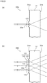
- Figures 3(a) and 3(b) are schematic cross-sectional views of the reticle 30A 1 taken along planes that intersect the pattern lines 32a and 32b at right angles.
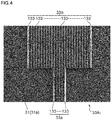
- Figure 4 is a micrograph of an enlarged portion of the pattern lines 32a and 32b.
- Figure 5 is a descriptive diagram for describing the state in which light incident from the side facing an object under observation on the protruding sections of the reticle 30A 1 exits out of the reticle 30A 1 .
- the pattern lines 32a and 32b of the reticle pattern 32 are formed of protruding sections 33a and 33b provided on the pattern formation surface 31a of the optical member 31.
- the protruding section 33a corresponds to the small-linewidth pattern line (thin linear pattern) 32a
- the protruding section 33b corresponds to the large-linewidth pattern line (thick linear pattern) 32b.
- the protruding sections 33a and 33b are each formed of a plurality of minute protruding ridges 133, 133, 133... extending in the lengthwise direction of the pattern lines in parallel to the width direction of the pattern lines.
- the protruding sections 33a and 33b are each formed of a plurality of protruding ridges 133 each having a width smaller than the linewidth of the pattern lines.
- the protruding ridges 133 are each formed to extend in the lengthwise direction of the pattern lines with the cross-sectional shape perpendicular to the direction in which the pattern lines extend having a triangular-prism-like shape that protrudes from the pattern formation surface 31a toward the object under observation.
- the inclination angles of two inclining surfaces 140, 140, which form each of the protruding ridges 133, with respect to the optical axis Z are each so set that the angles of the light that is incident on, refracted at, and deflected by the inclining surface and exits via the other surface of the optical member that is the surface facing the pattern formation surface 31a (hereinafter referred to as "opposite surface") 31b are greater than the angles of the light that passes through the ocular lens 4, which is provided on the downstream of the reticle 30A 1 .
- the inclination angles are so set that the light that is deflected by the protruding ridges 133, 133, 133...
- the two inclining surfaces 140, 140 of each of the protruding ridges 133 form refraction surfaces that refract the light incident thereon.
- the protruding sections 33a and 33b can each be formed of the protruding ridges 133 the number of which is set in accordance with the linewidth of the corresponding pattern line. That is, the protruding section 33a, which forms the thin linear pattern (small-linewidth pattern line) 32a, can be formed of a smaller number of protruding ridges 133, and the protruding section 33b, which forms the thick linear pattern (large-linewidth pattern line) 32b, can be formed of a larger number of protruding ridges 133.
- the protruding section 33a of the thin linear pattern 32a having a small linewidth w is formed of 5 protruding ridges 133
- the protruding section 33b of the thick linear pattern 32b having a large linewidth 5w is formed of 25 protruding ridges 133.
- the width of each of the protruding ridges 133 in the present configuration example is about 10 ⁇ m.
- the light incident from the side facing the object under observation (left in Figure 3 ) on the pattern formation surface 31a is so refracted at the inclining surfaces 140 of the protruding ridges 133, 133, 133..., as to be deflected in the direction away from the optical axis Z of the rifle scope RS and exits via the opposite surface 31b of the optical member.
- the exiting angles at which the light exits via the opposite surface 31b of the optical member are greater than exiting angles that allow the light to pass through the ocular lens 4, the light does not enter the eye 5 of the observer via the ocular lens 4.
- the light that is refracted at the inclining surfaces 140 and exits via the opposite surface 31b is, for example as shown in Figure 5 , absorbed by the inner circumferential surface of a lens barrel that holds the reticle 30A 1 , the ocular lens 4, and other components.
- the observer who looks at the object under observation, which is a mark, from the side facing the ocular lens 4 does not see the light from the portions where the protruding sections 33a and 33b are provided but visually recognizes the linear patterns 32a and 32b as dark lines and clearly observes the image of the reticle pattern 32.
- one pattern line is formed of a plurality of protruding ridges 133 according to the linewidth of the pattern line.
- the height of the protruding sections that protrude from the pattern formation surface 31a can therefore be greatly reduced, as compared with a case where the protruding sections 33a and 33b are each formed of a single protruding ridge. Therefore, the reticle can be configured to have a small thickness, and damage of the protruding sections 33a and 33b can be suppressed, whereby a reticle that is readily handled when stored, assembled, and otherwise processed can be provided.
- a uniform contrast reticle pattern irrespective of the linewidths of the pattern lines 32a and 32b can be produced by employing a configuration in which the pattern lines 32a and 32b are each formed of the protruding ridges 133 the number of which is proportional to the linewidth of the pattern line (by forming the protruding ridges at the same density per unit linewidth).
- a reticle 30A 2 according to a second configuration form that is part of the present embodiment will be described.
- the reticle 30A 2 according to the present configuration form has a configuration form in which the protruding ridges in the reticle 30A 1 according to the first configuration form are replaced with V grooves (V-letter-shaped grooves), that is, the structural elements provided on the pattern formation surface 31a are changed from the protruding ridges to the V grooves.
- Figures 6(a) and 6(b) correspond to the Figures 3(a) and 3(b) and are each a schematic cross-sectional view of the reticle 30A 2 taken along planes that intersect the pattern lines 32a and 32b at right angles.
- the pattern lines 32a and 32b of the reticle pattern 32 are formed of recessed sections 34a and 34b formed in the pattern formation surface 31a of the optical member.
- the recessed section 34a corresponds to the thin linear pattern (small-linewidth pattern line) 32a
- the recessed section 34b corresponds to the thick linear pattern (large-linewidth pattern line) 32b.
- the recessed sections 34a and 34b are each formed of a plurality of minute V grooves 134, 134, 134... extending in the lengthwise direction of the pattern lines in parallel to the width direction of the pattern lines.
- the recessed sections 34a and 34b are each formed of a plurality of V grooves 134 each having a width smaller than the linewidth of the pattern lines.
- the V grooves 134 are each formed to extend in the lengthwise direction of the pattern lines with the cross-sectional shape perpendicular to the direction in which the pattern lines extend having a V-letter-like shape that opens toward the pattern formation surface 31a.
- the inclination angles of two inclining surfaces (refraction surfaces) 140, 140, which form each of the V grooves 134, with respect to the optical axis Z are each so set that the angles of at least part of the light that is incident on, refracted at, and deflected by the inclining surface and exits via the opposite surface 31b are greater than the angles of the light that passes through the ocular lens 4, which is provided on the downstream of the reticle.
- the inclination angles are so set that the light that is deflected by the V grooves 134, 134, 134... and exits out of the reticle 30A 1 does not pass through the ocular lens 4 or enter the eye 5 of the observer.
- the recessed sections 34a and 34b can each be formed of the V grooves 134 the number of which is set in accordance with the linewidth of the corresponding linear pattern. That is, the recessed section 34a, which forms the thin linear pattern (small-linewidth pattern line) 32a, can be formed of a smaller number of V grooves 134, and the recessed section 34b, which forms the thick linear pattern (large-linewidth pattern line) 32b, can be formed of a larger number of V grooves 134.
- the recessed section 34a of the thin linear pattern 32a having the small linewidth w is formed of 3 V grooves 134
- the recessed section 34b of the thick linear pattern 32b having a large linewidth 4w is formed of 12 V grooves 134.
- the light incident from the side facing the object under observation on the pattern formation surface 31a is so refracted at the inclining surfaces 140 of the V grooves 134, 134, 134..., as to be deflected in the direction away from the optical axis Z of the rifle scope and exits via the opposite surface 31b of the optical member.
- the exiting angles at which the deflected light exits via the opposite surface 31b of the optical member are greater than exiting angles that allow the light to pass through the ocular lens 4, the light does not enter the eye 5 of the observer via the ocular lens 4.
- the observer who looks at the object under observation, which is a mark, from the side facing the ocular lens 4 does not see the light from the portions where the recessed sections 34a and 34b are provided but visually recognizes the linear patterns 32a and 32b as dark lines and clearly observes the image of the reticle pattern 32.
- one pattern line is formed of a plurality of V grooves 134 according to the linewidth of the pattern line.
- the depth of the recessed sections can therefore be greatly reduced, as compared with a case where the recessed sections are each formed of a single V groove.
- a reticle having a reduced thickness and improved resistance to impact and external force applied when a bullet is shot can therefore be provided.
- a uniform contrast reticle pattern irrespective of the linewidths of the pattern lines 32a and 32b can be produced by employing a configuration in which the pattern lines 32a and 32b are each formed of the V grooves 134 the number of which is proportional to the linewidth of the pattern line (by forming the V grooves at the same density per unit linewidth).
- the pattern lines 32a and 32b are formed of protruding/recessed sections 35a and 35b (protruding/recessed section 35b is not shown) formed in the pattern formation surface 31a of the optical member.
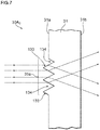
- Figure 7 shows a schematic cross-sectional view of the pattern line 32a corresponding to Figures 3(a) and 6(a) .
- the protruding/recessed section 35a has a complex configuration in which a protruding ridge 133, which protrudes from the pattern formation surface 31a toward the object under observation, and a V groove 134, which opens toward the pattern formation surface 31a, are alternately connected to each other.
- the protruding/recessed section 35a (and 35b) is so configured that the protruding ridge 133 and the V groove 134, the width of each of which is smaller than the linewidth of the linear patterns, are alternately provided.
- one pattern line is formed of a structure in which a plurality of protruding ridges 133 and V grooves 134 according to the linewidth of the pattern line are connected to each other.
- the height of the protruding ridges that protrude from the pattern formation surface 31a can be greatly reduced and the depth of the V grooves that are recessed from the pattern formation surface 31a can be greatly reduced, as compared with a case where the protruding/recessed sections are each formed of a single protruding ridge or V groove or a set of a protruding ridge and a V groove.
- the reticle can therefore be configured to have a small thickness. Further, a reticle that is readily handled when stored, assembled, and otherwise processed with damage of the protruding ridges suppressed and has increased resistance to impact and external force applied when a bullet is shot can be provided.
- a uniform contrast reticle pattern irrespective of the linewidths of the linear patterns 32a and 32b can be produced by employing a configuration in which the linear patterns 32a and 32b are each formed of the protruding ridges 133 and the V grooves 134 the number of each of which is proportional to the linewidth of the linear pattern.
- the inclination angle of the inclining surfaces (refraction surfaces) 140 of each of the protruding ridges 133 with respect to the optical axis Z of the rifle scope RS and the inclination angle of the inclining surfaces 140 of each of the V grooves 134 with respect to the optical axis Z are set in the same manner as in the configuration forms described previously, and are each so set that the deflected light having exited out of the reticle 30A 3 does not pass through the ocular lens 4 or enter the eye 5 of the observer.
- the numbers of protruding ridges 133 and the V grooves 134, which form each of the protruding/recessed sections 35a and 35b, can be set in accordance with the linewidth of the pattern line, that is, the numbers of protruding ridges 133 and the V grooves 134 of the protruding/recessed section 35a, which forms the thin linear pattern 32a, is set to be small, and the numbers of protruding ridges 133 and the V grooves 134 of the protruding/recessed section 35b, which forms the thick linear pattern 32b, is set to be large.
- the light incident from the side facing the object under observation (left in Figure 3 ) on the pattern formation surface 31a is so refracted at the inclining surfaces 140 of each of the protruding ridges 133 and the inclining surfaces 140 of each of the V grooves 134 as to be deflected in directions away from the optical axis Z of the rifle scope and exits out of the reticle 30A 3 .
- the exiting angles at which the deflected light exits out of the reticle 30A 3 are greater than exiting angles that allow the light to pass through the ocular lens 4, the light does not enter the eye 5 of the observer via the ocular lens 4 but is absorbed, for example, by the inner circumferential surface of the lens barrel that holds the reticle 30A 3 , the ocular lens 4, and other components.
- the observer therefore does not see the light from the portions where the protruding/recessed sections 35a and 35b are provided but visually recognizes the linear patterns 32a and 32b as dark lines and clearly observes the image of the reticle pattern 32.
- the reticle pattern 32 is formed of the protruding sections and/or the recessed sections provided on the pattern formation surface 31a of the optical member.
- the protruding sections 33a and 33b are each formed of a plurality of protruding ridges 133 extending in the lengthwise direction of the lines that form the reticle pattern 32 in parallel to the width direction of the lines, and the recessed sections 34a and 34b are each formed of a plurality of V grooves 134 extending in the lengthwise direction of the lines that form the reticle pattern 32 in parallel to the width direction of the lines.
- the protruding/recessed sections 35a and 35b are each formed of the combination of a plurality of protruding ridges 133 and V grooves 134 extending in the lengthwise direction of the lines that form the reticle pattern 32 in parallel to the width direction of the lines.
- the protruding sections are each formed of a plurality of protruding ridges
- the height of the protruding sections that protrude from the pattern formation surface 31a can be greatly reduced.
- a reticle that has a reduced thickness and is readily handled with damage of the protruding sections suppressed can therefore be provided.
- the recessed sections are each formed of a plurality of V grooves
- the depth of the recessed sections can be greatly reduced.
- a reticle that has a reduced thickness and improved resistance to impact and external force applied when a bullet is shot can therefore be provided.
- the protruding/recessed sections each have a structure that is the combination of protruding ridges and V grooves
- the height of the protruding ridges that protrude from the pattern formation surface 31a can be greatly reduced, and the depth of the V grooves that are recessed from the pattern formation surface 31a can be greatly reduced.
- a reticle that has a reduced thickness, is readily handled when stored, assembled, and otherwise processed with damage of the protruding ridges suppressed, and has improved resistance to impact and external force applied when a bullet is shot can therefore be provided.
- the reticles 30A changing the number of protruding ridges, the V grooves, and other components that form each of the pattern lines as appropriate allows a pattern line having a desired linewidth to be readily formed.
- a plurality of types of reticle having the same basic configuration of the reticle pattern but having different linewidths of the pattern lines that form the reticle pattern and different combinations thereof can be readily configured with no change in the plate thickness and other factors of the optical member 31.
- a uniform contrast reticle pattern can be produced with bright/dark unevenness of the pattern suppressed, as compared with the case where the protruding sections, the recessed sections, and other portions are each formed, for example, of a single protruding ridge or V groove.
- the inclining surfaces 140 are each formed of a flat surface by way of example, and the inclining surfaces may each instead be a curved surface, a parabolic surface, or any other surface.
- the inclination angle of the inclining surfaces (refraction surfaces) 140 that is so set that the light deflected by the inclining surfaces 140 does not enter the eye 5 of the observer will next be described with reference to the reticle 30A 1 out of the thus configured reticles 30A described above.
- ⁇ be the vertex angle of each of the protruding ridges 133 on the reticle 30A 1 and ⁇ /2 be the inclination angle of each of the inclining surfaces 140 with respect to the optical axis Z of the rifle scope RS, as shown in Figure 8 .
- the light incident on any of the inclining surfaces 140 is refracted in a direction closer to the optical axis Z as the inclination angle ⁇ /2 is greater whereas in a direction farther from the optical axis Z as the inclination angle ⁇ /2 is smaller.
- first predetermined angle ⁇ 1 /2
- first predetermined angle ⁇ 1 /2
- ⁇ 1 /2 can be determined based primarily on a light collection angle ⁇ of the objective lens 1, a refractive index n of the base material (optical member 31) of the reticle 30A 1 , and an aperture (light flux capturing angle) V of the ocular lens 4.
- the light collection angle ⁇ of the objective lens 1 ranges from about 10 to 30°
- the refractive index n of the reticle base material appropriate for injection molding ranges from about 1.46 to 1.53
- the light flux capturing angle V of the ocular lens 4 ranges from about 18 to 26°.
- the first predetermined angle ⁇ 1 /2 described above is therefore roughly specified by the light flux capturing angle V of the ocular lens 4.
- the first predetermined angle ⁇ 1 /2 ranges from 54 to 58° in a case where an optical system using an ocular lens 4 having a light flux capturing angle V of 18°, and the first predetermined angle ⁇ 1 /2 ranges from 42 to 47° in a case where an optical system using an ocular lens 4 having a light flux capturing angle V of 26°.
- the refractive index n of the base material of the reticle ranges from about 1.43 to 1.8.
- the first predetermined angle ⁇ 1 /2 described above ranges from 52 to 70° in the case where an optical system using an ocular lens 4 having a light flux capturing angle V of 18°
- the first predetermined angle ⁇ 1 /2 ranges from 39 to 62° in the case where an optical system using an ocular lens 4 having a light flux capturing angle V of 26°.
- the protruding ridges 133 are replaced with the V grooves 134.
- the inclination angle ⁇ /2 of each of the inclining surfaces 140 is preferable to be greater than or equal to the predetermined angle.
- the predetermined angle described above from this point of view (called “second predetermined angle” for convenience) ⁇ 1 /2 can be determined based primarily on the light collection angle ⁇ of the objective lens 1, the refractive index n of the base material of the reticle 30A 1 , and the light flux capturing angle V of the ocular lens 4.
- the second predetermined angle ⁇ 2 /2 ranges from 21 to 22° when the light flux capturing angle V of the ocular lens 4 is 18°, and the second predetermined angle ⁇ 2 /2 ranges from 23 to 24° when the light flux capturing angle V is 26°.
- the second predetermined angle ⁇ 2 /2 ranges from 23 to 24° when the light flux capturing angle V of the ocular lens 4 is 18°, and the second predetermined angle ⁇ 2 /2 ranges from 25 to 26° when the light flux capturing angle V is 26°.
- the protruding ridges 133 are replaced with the V grooves 134.
- the second predetermined angle ⁇ 2 /2 ranges from 21 to 24° when the light flux capturing angle V of the ocular lens 4 is 18°, and the second predetermined angle ⁇ 2 /2 ranges from 23 to 25° when the light flux capturing angle V is 26°.
- the second predetermined angle ⁇ 2 /2 ranges from 23 to 25° when the light flux capturing angle V of the ocular lens 4 is 18°, and the second predetermined angle ⁇ 2 /2 ranges from 25 to 27° when the light flux capturing angle V is 26°.
- the protruding ridges 133 are replaced with the V grooves 134.
- the inclination angle ⁇ /2 of each of the inclining surfaces 140 of each of the protruding ridges 133 is preferably smaller than or equal to the first predetermined angle ⁇ 1 /2 and further preferably set to fall within an angular range greater than or equal to the second predetermined angle ⁇ 2 /2 ( ⁇ 2 /2 ⁇ /2 ⁇ 1 /2).
- setting the inclination angle ⁇ /2 of each of the inclining surfaces 140 so as to satisfy 21° ⁇ /2 ⁇ 70° allows clear visual recognition of the pattern lines 32a and 32b through a rifle scope using a reticle made of a relatively high-refractive-index base material suitable for glass molding and injection molding.
- a reticle 30 according to a second embodiment will next be described.
- the reticle 30B according to the second embodiment is so configured that the pattern lines 32a and 32b are not dark lines but transmit part of the light from an object under observation and the observer can visually recognize the object under observation through the pattern lines.
- the reticle 30B according to the second embodiment differs from the reticles 30A (30A 1 , 30A 2 , and 30A 3 ) according to the first embodiment having been already described in terms of only part of the cross-sectional shape of the protruding ridges 133, which are the structural elements that form the protruding sections 33a and 33b, the cross-sectional shape of the V grooves 134, which are the structural elements that form the recessed sections 34a and 34b, and the cross-sectional shapes of the protruding ridges 133 and the V grooves 134, which are the structural elements that form the protruding/recessed sections 35a and 35b, and the reticle 30B according to the second embodiment is the same as the reticles 30A (30A 1 , 30A 2 , and 30A 3 ) according to the first embodiment in terms of the other configurations.
- the same components have the same numerals and will not be redundantly be described, and different portions will be
- Figure 9 is a schematic cross-sectional view taken along a plane perpendicular to the pattern line 32a, and a reticle 30B 1 according to a first configuration form will be described with reference to this figure.
- the reticle 30B 1 is so configured that a light transmissive surface 145, which transmits the light incident from the side facing the object under observation so that the observer can visually recognize the transmitted light, is provided between a pair of inclining surfaces 140, 140, which form each of the protruding ridges 133.
- the light transmissive surface 145 has an aspect in which it truncates a top portion of the protruding ridge 133 to form a flat top portion, and the light transmissive surface 145 is formed to be roughly parallel to the pattern formation surface 31a and connect the right and left inclining surfaces 140, 140 to each other.
- the light incident on any of the inclining surfaces 140 is so refracted at the inclining surface 140 as to be deflected in a direction away from the optical axis Z and exits via the opposite surface 31b of the optical member.
- the deflected light is guided to exit out of the optical path and is therefore invisible to the observer, but a dark line image enters the observer's eye.
- the light incident on the light transmissive surface 145 is hardly refracted at the light transmissive surface 145 but exits via the opposite surface 31b along the optical axis Z of the rifle scope RS.
- the light having exited via the opposite surface 31b passes through the ocular lens 4, and a partial image of the object under observation enters the eye 5 of the observer.
- Figure 10 is a descriptive diagram for describing how the observer recognizes the images described above in a situation in which the pattern line 32b overlaps with an object under observation T.
- Figure 10(a) shows a case where any of the reticles 30A according to the first embodiment is used
- Figure 10(b) shows a case where any of the reticles 30B according to the second embodiment is used.
- the pattern line 32b is a dark line, so that the observer sees no image of a portion of the object under observation T that is the portion with which the pattern line 32b overlaps, as shown in Figure 10(a) .
- the portion corresponding to the pattern line 32b has a state in which a plurality of dark line images are combined with a partial transmitted image of the object under observation T, as shown in Figure 10(b) .
- the observer therefore visually recognizes both the image of the pattern line 32b and the image of the object under observation and observes the object under observation T through the dim pattern line 32b.
- the situation described above is similar to a situation in which a light blocking portion that transmits no light and a slit portion that transmits light are so alternately formed on a transparent glass plate as to be in close contact with each other to form a slit plate and an object under observation is observed through the slit plate.
- Figure 9 shows by way of example the configuration in which each of the light transmissive surfaces 145 is provided between a pair of inclining surfaces 140, 140 (at top of protruding ridge), which form a protruding ridge 133.
- the light transmissive surfaces 145 may each instead be provided between two inclining surfaces 140, 140 (at bottom between adjacent protruding ridges) of adjacent protruding ridges 133 133 that are the inclining surfaces 140, 140 face each other, or the light transmissive surfaces 145 may be provided both at the tops of the protruding ridges and the bottoms between the protruding ridges.
- Figure 11 is a cross-sectional view of a reticle 30B 2 according to a second configuration form taken along a plane perpendicular to the pattern line 32a.
- the reticle 30B 2 is so configured that the light transmissive surface 145, which transmits the light incident from the side facing the object under observation so that the observer can visually recognize the transmitted light, is provided between a pair of inclining surfaces 140, 140 (at bottom of V groove), which form each of the V grooves 134.
- the light transmissive surface 145 has an aspect in which it buries the bottom of the V groove 134 to form a flat raised bottom, and the light transmissive surface 145 is formed to be roughly parallel to the pattern formation surface 31a and connect the right and left inclining surfaces 140, 140 to each other.
- the light incident from the side facing the object under observation behaves in the same manner as in the reticle 30B 1 according to the first configuration form. That is, out of the light incident from the side facing the object under observation on the reticle 30B 2 , the light incident on any of the inclining surfaces 140 is so refracted at the inclining surface 140 as to be deflected in a direction away from the optical axis Z of the rifle scope RS and exits out of the optical path, so that the deflected light does not enter the observer's eye, but a dark line image enters the observer's eye.
- the light incident on the light transmissive surface 145 is hardly refracted at the light transmissive surface 145 but travels along the optical axis Z, and a partial image of the object under observation enters the observer's eye.
- the portion corresponding to the pattern line 32b has the state in which a plurality of dark line images are combined with a partial transmitted image of the object under observation T, and the observer observes the object under observation T through the dim pattern line 32b, as shown in Figure 10(b) .
- Figure 11 shows by way of example the configuration in which each of the light transmissive surfaces 145 is provided between a pair of inclining surfaces 140, 140 (at bottom of V groove) that form a V groove 134, and the light transmissive surface 145 may instead be provided between two inclining surfaces 140, 140 of adjacent V grooves 134, 134 (at top between adjacent V grooves) that are the inclining surfaces 140, 140 disposed back to back, or the light transmissive surfaces 145 may be provided both at the bottoms of the V grooves and the tops between the V grooves.
- a reticle 30B 3 according to a third configuration form is so configured that the flat light transmissive surface 145 is provided at the top of each of the protruding ridges 133 and/or the bottom of each of the V grooves 134 in each of the protruding/recessed sections 35 formed of the plurality of protruding ridges 133 and V grooves 134.
- Figure 12 is a cross-sectional view of a protruding/recessed section 35a having a configuration in which the light transmissive surface 145 are formed both at the tops of the protruding ridges 133 and the bottoms of the V grooves 134.
- the protruding/recessed section 35a has a structure in which the reticle 30B 1 according to the first configuration form described above is integrated with the reticle 30B 2 according to the second configuration form described above, and the light incident from the side facing the object under observation behaves in the same manner as in the reticles 30B 1 and 30B 2 according to the first and second configuration forms having been already described.
- the light incident on any of the inclining surfaces 140 is deflected in a direction away from the optical axis Z of the rifle scope RS and exits out of the optical path, so that the deflected light does not enter the observer's eye, but a dark line image enters the observer's eye.
- the observer recognizes the plurality of line images integrated with one another as images of the pattern lines 32a and 32b.
- the portion corresponding to the pattern line 32b has the state in which a plurality of dark line images are combined with a partial transmitted image of the object under observation T, and the observer observes the object under observation T through the dim pattern line 32b, as shown in Figure 10(b) .
- Figure 12 shows by way of example the configuration in which the light transmissive surfaces 145 are each provided between a pair of inclining surfaces 140, 140 (at top of protruding ridge) that form a protruding ridge 133 and between a pair of inclining surfaces 140, 140 (at bottom of V groove) that form a V groove 134, and the light transmissive surface 145 may each instead be provided only on one of the two portions described above (at top of protruding ridge, for example).
- configuration ratios ⁇ of the light transmissive surface 145 to the protruding sections 33 (33a and 33b), the recessed sections 34 (34a and 34b), and the protruding/recessed sections 35 (35a and 35b) can each range from 1 to 99%.
- Figures 13(a), 13(b), and 13(c) are descriptive diagrams schematically showing a view of the object under observation T and the pattern line 32b with the configuration ratio ⁇ of the light transmissive surface 145 changed.
- the magnitudes of the configuration ratios ⁇ of the light transmissive surface 145 in Figures 13(a), 13(b), and 13(c) satisfy ⁇ 1 ⁇ 2 ⁇ 3 in the order of Figures 13(a), 13(b), and 13(c) .
- the configuration ratio ⁇ of the light transmissive surface 145 is the clearer the pattern line 32b is visually recognized, and the greater the configuration ratio ⁇ of the light transmissive surface 145 is, the clearer the object under observation T is visually recognized, as shown in Figures 13(a), 13(b), and 13(c) .
- the configuration ratio of the light transmissive surface 145 is roughly equal in the meaning to the optical transmittance along the optical axis.
- Contrast identification capability of a human eye ranges from about 1 to 2% (Weber-Fechner law). That is, a human eye can identify two objects that differ from each other in terms of luminance by about 1%. A person can therefore identify a pattern line in a bright background when the brightness of the pattern line is lower than that of the background by about 1% and identify an object under observation in a dark pattern line when the brightness of the object under observation is higher than that of the pattern line by about 1%.
- the configuration ratios ⁇ of the light transmissive surface 145 preferably each ranges from 10 to 40%. The reason for this is that fine movement of the object under observation T is unlikely to be visually recognized when ⁇ 10%, whereas the density of the pattern lines 32a and 32b decreases when ⁇ >40%, and it is therefore difficult to sight the rifle on a target.
- the configuration ratios ⁇ of the light transmissive surface 145 more preferably each ranges from 25 to 30%.
- a human eye is believed to have resolution of about 0.1 mm.
- the person when a person observers a structure in which two bright lines are formed side by side in a dark background with a naked eye, the person recognizes the bright lines as two lines when the distance between the lines is greater than 0.1 mm, whereas the person recognizes the bright lines as one line when the distance between the lines is smaller than 0.1 mm.
- the person when a person observers a structure in which two dark lines are formed side by side in a bright background with a naked eye, the person recognizes the dark lines as two lines when the distance between the lines is greater than 0.1 mm, whereas the person recognizes the dark lines as one line when the distance between the lines is smaller than 0.1 mm.
- the distance between adjacent light transmissive surface 145 and the distance between adjacent inclining surfaces 140 of the reticle pattern 32 at which the observer looks are each smaller than or equal to 0.1 mm.
- the rifle scope RS an image of any of the reticles 30B is enlarged by the ocular lens 4 and enters the observer's eye.
- the ocular lens 4 provides a magnification of 5
- the distance between the light transmissive surfaces 145 and the distance between the inclining surfaces 140 in plainer words, the interval at which the protruding ridges 133 and the V grooves 134 are formed can be set in accordance with the configuration of the optical system using any of the reticles 30.
- the above-mentioned configuration ratio ⁇ of the light transmissive surface 145 can be set at a different value in accordance with the widthwise or lengthwise position in a pattern line.
- a pattern line 32b of a reticle 30B 4 shown in Figure 14 in which the protruding ridges 133 located in an outer area in the linewidth direction have the configuration ratio ⁇ of the light transmissive surface 145 set at a small value (low transmittance of light from object under observation), and the protruding ridges 133 located in an inner area in the linewidth direction have the configuration ratio ⁇ of the light transmissive surface 145 set at a large value (high transmittance of light from object under observation).
- protruding ridges 133 located at the outer edges in the linewidth direction have a configuration ratio that allows the line to remain black even when the intensity of outside light and the magnification of the optical system change
- protruding ridges 133 located in the area inside the outer edges in the linewidth direction have a configuration ratio that allows visual recognition of a target even when the intensity of outside light and the magnification of the optical system change.
- the observer can readily sight the rifle on the target because the contour of the pattern line 32b is a dark line and is therefore clearly visually recognized, and even in a case where the target captured within the field of view is small, the observer can sight the rifle on the target without losing track of the target because the object under observation can be visually recognized inside the pattern line 32b.
- the observer can readily sight the rifle on the target because the pattern line 32b is clearly visually recognized on the side facing the outer circumference of the reticle pattern 32, and even in the case where the target captured within the field of view is small, the observer can sight the rifle on the target without losing track of the target because the target can be visually recognized inside the pattern line 32b in an area close to the center of the reticle pattern 32.
- the example described above relates to a configuration in which a large linewidth pattern line 32b is used, and the same holds true for a small linewidth pattern line 32a.
- Figures 16(a), 16(b), and 16(c) show specific configuration examples.
- Figure 16(a) shows a configuration example in which a convex light transmissive surface 145 having a radius of curvature r is formed at the top of each of the protruding ridges 133.
- Figure 16(b) shows a configuration example in which a concave light transmissive surface 145 having a radius of curvature -r is formed at the top of each of the protruding ridges 133.
- Figure 16(c) shows a configuration example in which a concave light transmissive surface 145 having the radius of curvature - r is formed at the bottom of each of the V grooves 134.
- the light transmissive surface 145 are each a curved surface
- the light incident on the light transmissive surface 145 diverges at a spread angle according to the curvature of the light transmissive surface, and part of the incident light passes through the ocular lens 4 and enters the observer's eye.
- the observer can, however, visually recognize the partial image of the object under observation with no large distortion as long as the radius of curvature of each of the light transmissive surface 145 is greater than or equal to the predetermined value.
- the predetermined value described above varies in accordance with the configuration of the rifle scope, the brightness of an object under observation, and other factors, and an image of the object under observation can be visually recognized as long as the radius of curvature is roughly greater than or equal to 2 ⁇ m.
- the linear patterns 32a and 32b of the reticle pattern 32 are formed of a cluster of a plurality of structural elements in the form of the protruding ridges 133 or the V grooves 134, and the optical refraction effect provided by the inclining surfaces 140 of each of the structural elements guides the light incident on the reticle pattern 32 in such a way that the incident light exits out of the optical path along which the observer observes the reticle pattern.
- the configuration described above prevents the light incident on the inclining surfaces 140 of each of the structural elements from reaching the eye 5 of the observer but allows the observer to recognize the reticle pattern 32 in the form of the black lines of the linear patterns 32a and 32b.
- the basics of the configuration described above relies on the fact that light from the "structural elements” that form the reticle pattern is guided to exit out of the observation optical path of the ocular lens 4, as shown in Figure 5 , and have basically nothing to do with the direction of the pattern or the direction of the structural elements, such as the protruding ridges and the V grooves. Therefore, the protruding ridges 133 or the V grooves 134 are not necessarily oriented in the lengthwise direction of the linear patterns and can be disposed to be perpendicular to the lengthwise direction of the linear patterns or oriented in an arbitrary direction.
- the protruding ridges and the V grooves are each long in the direction in which the ridge lines extend but very short in the direction perpendicular to the extending direction, and the length of the ridge lines (length of pattern lines) is arbitrary.
- the protruding ridges and the V grooves can each be formed of a short line.
- a reticle 30C according to a third embodiment has a configuration in which structural elements that form a protruding section and/or a recessed section are each a pyramidal element and an inclining side surface extending from the top of the pyramid to the bottom thereof, that is, the pyramidal surface is used as the refraction surface.
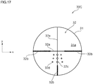
- Figure 17 shows a reticle having a pattern different to some extent from the pattern shown in Figure 2 , and the reticle 30C according to the present embodiment will be described with reference to Figures 17 and 18 to 25 .
- the reticle pattern 32 of the reticle 30C shown in Figure 17 is formed of a plurality of ring-shaped or annular partial patterns (called ring-shaped patterns) 32c each having a relatively small diameter and a plurality of cross-shaped partial patterns (called cross patterns) 32d each having a relatively small size in the field of view of the ocular lens in addition to the cross pattern formed of the thin linear patterns 32a and the thick linear patterns 32b, which divide the field of view into four parts, as in the reticles 30A and 30B described with reference to Figure 2 .
- the ring-shaped patterns 32c and the cross patterns 32d are each formed of a plurality of pyramidal structural elements.
- FIG. 18 As a reticle according to a first configuration form that is part of the present embodiment, a description will be made of a configuration in which the ring-shaped patterns 32c are each formed of a plurality of conical structural elements that protrude from the pattern formation surface 31a.
- Figures 18 to 20 show a first configuration example of each of the ring-shaped patterns 32c.
- Figure 18 is a partially enlarged view of each of the ring-shaped patterns 32c shown in Figure 17 .
- Figure 19 is a perspective view of the area indicated by the reference character XIX in Figure 18 .
- Figure 20 is a cross-sectional view taken along the arrowed line XX-XX in Figure 18 .
- the ring-shaped patterns 32c are each the protruding section 33a formed of a plurality of conical structural elements 135a, 135b, and 135c and are each a curved partial pattern that forms the reticle pattern 32.
- the ring-shaped patterns 32c are each formed by arranging a plurality of conical structural elements along a circle in such a way that the bottom edges of the conical structural elements are in contact with each other to form a single-row circular pattern and setting conical structural elements along the inner and outer circumferences adjacent to the single-row circular pattern in such a way that the bottom edges of the conical structural elements are in contact with each other to form multiple-row (three rows in Figure 18 ) circular patterns in a concentric manner.
- the structural element 135b which is the center-row circular pattern out of the three rows, has a configuration in which not only are bottom edges 141b of right and left structural elements in the same row in contact with each other but the bottom edges 141b are in contact with bottom edges 141a of two structural elements 135a, 135a in the inner circumferential row and the bottom edges 141b are in contact with bottom edges 141c of two structural elements 135c, 135c in the outer circumferential row. That is, the plurality of conical structural elements are so densely arranged in accordance with the shape of the partial pattern that the bottom edges 141a, 141b, and 141c of the structural elements are contact with each other.
- the structural elements 135a, 135b, and 135c, which form the rows, have the same vertex angle of the cones (conical angle) ⁇ but have different sizes (different diameters of bottom edges 141a, 141b, and 141c and different heights of cones), that is, the structural elements 135a on the inner circumferential side are each formed of a cone having a small height (having a small diameter of bottom edge 141a) with respect to the cone that forms each of the structural elements 135b in the central row, and the structural elements 135c on the outer circumferential side are each formed of a cone having a large height (having a large diameter of bottom edge 141c) with respect to the cone that forms each of the structural elements 135b in the central row.
- the side surfaces of the structural elements 135a, 135b, and 135c that is, pyramidal surfaces 140a, 140b, and 140c of the cones are each an inclining surface inclining by ⁇ /2 with respect to the optical axis Z of the rifle scope RS (axially symmetric inclining surface) and are each a refraction surface that refracts the light incident via the objective lens 1.
- the light incident via the objective lens 1 is therefore refracted at the side surfaces 140a, 140b, and 140c of the structural elements 135a, 135b, and 135c, separates away from the optical axis Z, and is guided to exit out of the observation optical path of the ocular lens 4, as described with reference to Figures 3 and 5 and other figures.
- the light refracted at the side surfaces (140a, 140b, and 140c) of the structural elements 135 (135a, 135b, and 135c) therefore does not enter the eye 5 of the observer via the ocular lens 4, and the observer visually recognizes the ring-shaped patterns 32c in the form of dark pattern images superimposed on an image of the object under observation.
- the ring-shaped patterns 32c formed of the multiple-row circular patterns are so densely arranged that the bottom edges 141a, 141b, and 141c of the structural elements 135a, 135b, and 135c, which form the rows, are in contact with each other.
- a reticle having a relatively plain configuration and having curved partial patterns, such as the ring-shaped patterns 32c, can therefore be provided.
- the structural elements 135a, 135b, and 135c, which form the rows have the same vertex angle ⁇ of the cones but have different heights of the cones and different diameters of the bottom edges 141a, 141b, and 141c.
- a diamond indenter having a conical shape having a vertex angle ⁇ is pressed against a die surface of a forming die to form conical recesses so shaped as to mate with the shapes of the structural elements 135a, 135b, and 135c.
- the conical recesses corresponding to the structural elements 135a, 135b, and 135c can be readily formed by adjusting the pressing force exerted on the diamond indenter, which presses the die surface, to control the depth to which the diamond indenter penetrates into the die surface.
- the single diamond indenter can therefore readily form conical recesses corresponding to a plurality of types of structural element having different sizes, whereby the die manufacturing cost can be reduced.
- Figure 21 shows a second configuration example of the ring-shaped patterns 32c.
- Figure 21 is a partially enlarged view of each of the ring-shaped patterns 32c according to the present configuration example.
- the ring-shaped pattern 32c shown in Figure 21 is also formed by arranging conical structural elements along a circle to form a single-row circular pattern and further forming multiple-row (basically three rows in Figure 21 ) circular patterns having different diameters in a concentric manner, as is the ring-shaped patterns according to the first configuration example.
- the vertex angles ⁇ and the sizes of conical structural elements 135d are equal to one another irrespective of which row each of the structural elements 135d belongs to, and the circumferential orientations of the structural elements 135d and angular intervals at which the structural elements 135d are arranged are also equal to one another (10° in the present configuration example).
- imaginary circles 141d, 141d which represent the bottom edges of the right and left conical structural elements 135d, 135d adjacent each other, overlap with each other, and in inner and outer circumferential circular patterns adjacent to each other, the imaginary circles 141d, 141d, which represent the bottom edges of the right and left conical structural elements 135d, 135d adjacent each other, overlap with each other.
- an additional circular pattern in an intermediate row is formed between the circular pattern in the outer circumferential row and the circular pattern in the central row with the circumferential angular positions of the structural elements 135d in the intermediate row shifted by a half interval (5°) from those of the circular patterns in the three rows.
- an outer-circumferential-row additional circular pattern is formed along the same circumference along which the outer-circumferential-row circular pattern is formed with the circumferential angular positions of the structural elements 135d of outer-circumferential-row additional circular pattern shifted by a half interval (5°) from those of the circular patterns in the three rows (in the same circumferential angular positions as those in the intermediate-row additional circular pattern).
- the circular pattern in the outer circumferential row has a configuration in which the structural elements 135d are densely formed at 1/2 angular intervals as compared with the circular patterns in the central row and the inner circumferential row.
- an additional circular pattern in an intermediate row is provided between the outer circumferential row and the central row, so that the density of the structural elements 135d increases toward the outer circumference.
- each of the structural elements 135d (pyramidal surface of cone) are each an inclining surface inclining by ⁇ /2 with respect to the optical axis Z of the rifle scope RS and are each a refraction surface that refracts the light incident via the objective lens 1.
- the light incident via the objective lens 1 is therefore refracted at the side surfaces of the structural elements and guided to exit out of the observation optical path of the ocular lens 4.
- the observer therefore visually recognizes the ring-shaped patterns 32c in the form of dark pattern images superimposed on an image of the object under observation.
- the imaginary circles 141d, 141d which represent the bottom edges of the right and left conical structural elements 135d, 135d adjacent each other in the same row, overlap with each other, and in inner and outer circumferential circular patterns adjacent to each other, the imaginary circles 141d, 141d, which represent the bottom edges of the conical structural elements 135d, 135d, overlap with each other.
- the configuration ratio of the refraction surfaces (inclining surfaces inclining by ⁇ /2 with respect to optical axis Z) 140 to the entire ring-shaped pattern 32c can be increased, as compared with the case where the bottom edges of the adjacent conical structural elements are in contact with each other, whereby the visibility of the pattern can be improved.
- the structural elements of the outer circumferential circular pattern are arranged at small intervals (at high density), the observer visually recognizes the contour of each of the ring-shaped patterns 32c as a smooth curve, and there is no light transmissive surface that does not refract the light incident thereon but directly transmits the incident light, whereby a reticle that provides high contrast and good visibility can be provided.
- FIG. 22 is a perspective view of the area indicated by the reference character XXIII in Figure 22 .
- Figure 24 is a cross-sectional view taken along the arrowed line XXIV-XXIV in Figure 22 .
- the cross patterns 32d are each the protruding section 33a formed of a plurality of quadrangular pyramidal structural elements 136, 136, 136... and are each a linear partial pattern that forms the reticle pattern 32.
- the cross patterns 32d are each configured by linearly arranging quadrangular pyramidal structural elements 136 in such a way that bottom edges 143 thereof are in contact with each other to form a one-row minute line, arranging the minute line in a plurality of rows (three rows in Figure 22 ) in parallel to one another to form a single short line, and further arranging the short line in two directions in such a way that the short lines interest each other at right angles in the form of a cross.
- the plurality of quadrangular pyramidal structural elements 136, 136, 136... are so densely arranged in accordance with the shape of the partial pattern that the bottom edges 141 of the structural elements 136 are in contact with each other.
- the structural elements 136, 136, 136... are each a regular quadrangular pyramid, and the vertex angles (angle made by side surfaces of structural element) ⁇ and the sizes (length of bottom edge 143, height of quadrangular pyramid) of the structural elements 136 arranged in the respective positions are equal to one another.
- the four side surfaces 140, 140, 140, 140 of each of the structural elements 136 are each an inclining surface inclining by ⁇ /2 with respect to the optical axis Z of the rifle scope RS and are each a refraction surface that refracts the light incident via the objective lens 1.
- the light incident via the objective lens 1 is therefore refracted at the side surfaces 140 of the structural elements to depart from the optical axis Z and is guided to exit out of the observation optical path of the ocular lens 4.
- the light refracted at the side surfaces 140 of the structural elements 136 therefore does not enter the eye 5 of the observer via the ocular lens 4, and the observer visually recognizes the cross patterns 32d in the form of dark pattern images superimposed on an image of the object under observation.
- Figure 25 shows a configuration example in which a letter pattern 32e, which represents the alphabetical letter "F", is formed by a plurality of quadrangular pyramidal structural elements 136, 136, 136..., which protrude from the pattern formation surface 31a.
- Figure 25 is a partially enlarged view of the letter pattern 32e similar to that shown in Figure 22 .
- the side surfaces 140 of each of the structural elements 136 are each an inclining surface inclining by ⁇ /2 with respect to the optical axis Z of the rifle scope RS and are each a refraction surface that refracts the light incident via the objective lens 1.
- the light incident via the objective lens 1 is therefore refracted at the side surfaces 140 of the structural elements, separates away from the optical axis Z, and is guided to exit out of the observation optical path of the ocular lens 4.
- the light refracted at the side surfaces 140 therefore does not enter the eye 5 of the observer via the ocular lens 4, and the observer visually recognizes the letter pattern 32e in the form of a dark pattern image superimposed on an image of the object under observation.
- a configuration ratio ⁇ of the refraction surfaces (inclining surfaces inclining by ⁇ /2 with respect to optical axis Z) 140 to each of the entire partial patterns 32d and 32e can be roughly 100% ( ⁇ 100%).
- the structural elements 136 are densely arranged with no gap therebetween in the partial pattern and along the contour thereof. A reticle that has a clear pattern shape and provides high contrast and good visibility can therefore be provided.
- the structural elements 135 (135a, 135b, 135c, and 135d), which each have a conical shape, and the structural elements 136, which each have a regular quadrangular pyramidal shape, have been presented as examples of the pyramidal structural elements, but the shape of the structural elements is not limited thereto. That is, the structural elements each only need to be so configured that the inclination angle of the inclining surface that is the side surface of the pyramidal shape and forms a refraction surface with respect to the optical axis Z is ⁇ /2.
- the structural elements may each be a triangular pyramid, a quadrangular pyramid having bottom edges that differ from one another in length, a pentagonal pyramid, a hexagonal pyramid, or any other polygonal pyramid.
- a plurality of pyramidal structural elements form a relatively small partial pattern in the field of view of the ocular lens
- a plurality of pyramidal structural elements can instead form a relatively large partial pattern in the field of view.
- the "short line" described with reference to the cross patterns 32d can be provided in an appropriate number of rows and extended to form each of the linear patterns 32a and 32b having been already described.
- the present embodiment has been described with reference to the configuration in which the ring-shaped patterns 32c, the cross patterns 32d, and the letter pattern 32e are each formed as the protruding section 33a, which protrudes from the pattern formation surface 31a, but needless to say, these partial patterns can each instead be configured as the recessed section 34, which is recessed more than the pattern formation surface 31a, to achieve the same function.
- the detailed configuration relating to the angle ⁇ /2 of the inclining surfaces 140 as the refraction surface described with reference to Figure 8 also holds true for the reticle 30C according to the present embodiment.
- the fact that the brightness of a pattern portion can be controlled by employing the configuration in which the top or bottom of each of the structural elements is partially formed of a flat surface as described in the second embodiment with reference to Figures 9 to 16 is also applicable to the reticle 30C according to the present embodiment.
- the reticles 30 (30A, 30B, and 30C) can be produced by using a plurality of types of manufacturing method in accordance with the material of the optical member 31 and the form of the reticle pattern 32.
- a description will be made of a manufacturing method used in a case where the material of the optical member 31 is a transparent resin material typically used with an optical apparatus and the reticle is produced in injection molding using a forming die.
- the method for manufacturing any of the reticles 30 includes the following steps (processes/procedures):
- the material of the die can be a material typically used in injection molding, for example, STAVAX provided by BOHLER-UDDEHOLM.
- the metal plating performed on the die surface only needs to provide relatively high surface hardness (higher than or equal to Vickers hardness of 450, more preferably higher than or equal to Vickers hardness of 800, for example) and allow formation of a plated layer thicker than the height of the structural elements, for example, electroless nickel plating and hard chrome plating.
- Means for forming the minute structures corresponding to the structural elements in the die surface can be selected as appropriate in accordance with the shape of the structural elements, which form the reticle pattern.
- the structural elements are, for example, the linear protruding ridges 133 or V grooves 134, which each have a length 1 in the direction of the pattern is greater than a width b in the direction perpendicular to the pattern (b ⁇ l), as in the case of the reticle 30A according to the first embodiment and the reticle 30B according to the second embodiment
- the minute structures corresponding to the structural elements are preferably formed by cutting-based formation (called "cutting method" for convenience).
- the structural elements are formed of a cluster of cones, quadrangular pyramids, or any other pyramids arranged in accordance with the shape of the pattern
- the cutting method and the indentation method can be combined with each other as appropriate in accordance with the configuration of the reticle pattern 32.
- the thus produced die is placed in an injection molding machine, and a transparent resin material is injected into the die to form any of the reticles 30 (30A, 30B, and 30C).
- a transparent resin material suitable for an optical apparatus such as a reticle, may include DELPET (registered trademark) 80N provided by Asahi Kasei Corp.
- the step of forming an antireflection film to the structural element group that form the protruding sections 33, the recessed sections 34, and the protruding/recessed sections 35 can be added.
- the antireflection film may be formed on the front surface of the reticle 30.
- the reticle manufactured by carrying out the steps described above was actually attached to a telescope for checking the field of view.
- the checking showed that the reticle pattern 32 formed on the reticle was successfully observed as a clear dark pattern.
- a reticle unit 3 including a pointer at the center of the reticle pattern 32 will next be described as a fifth embodiment with reference to Figures 26 to 28.
- Figures 26 to 28 are descriptive diagrams for describing the configuration of the reticle unit 3.
- Figure 26 is a descriptive diagram for describing the optical path of illumination light.
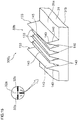
- Figure 27 is a perspective view of a reflector formed on the pattern formation surface 31a of the reticle.
- Figure 28 is a front view of the reticle unit showing the state in which the illumination light is projected on the reticle pattern 32.
- the reticle unit 3 includes a reticle 30D, a light source 38, which radiates the illumination light, and a light collector (condenser lens, for example) 39, which collects the light radiated from the light source 38.
- the reticle 30D is based on any of the reticles 30A 1 to 30A 3 described as the first embodiment, any of the reticles 30B 1 to 30B 5 described as the second embodiment, or the reticle 30C described as the third embodiment and further includes a reflector 37, which is provided on the pattern formation surface 31a of the optical member and has a reflection surface.
- the reflector 37 is provided in the form of a recessed section 37a, which opens in a roughly central portion of the pattern formation surface 31a of the optical member 31, and part of the surface that forms the recessed section 37a forms a reflection surface 37c.
- the reflector 37 has the shape of an obliquely cut cylinder in appearance, and the reflection surface 37c projected on the pattern formation surface 31a has a circular shape.
- the reflector 37 is located at the intersection of a pattern line extending in the axis-x direction and a pattern line extending in the axis-y direction in the crosshair-shaped reticle pattern 32, that is, at the center of the disc-shaped reticle 30D and is formed on the side facing the pattern formation surface 31a of the optical member 31 (side facing object under observation).
- the illumination light radiated from the light source 38 is collected by the light collector 39, and an image of the light source 38 is formed on the reflection surface 37c of the reflector 37.
- the image of the light source 38 is reflected off the reflection surface 37c in the direction of the optical axis of the rifle scope RS (axis-Z direction) and exits via the opposite surface 31b of the optical member.
- the ocular lens 4 is configured to allow visual recognition of an image of the reticle pattern 32 superimposed on the secondary image IM2.
- the reflection surface 37c is provided within the depth of focus of the ocular lens 4, whereby the observer can observe also the image of the light source 38 reflected off the reflection surface 37c. The observer can therefore visually recognize the image of the light source 38 in the form of a dot image at the center of the reticle pattern 32, that is, on the optical axis of the rifle scope RS.
- the light collector 39 is configured to guide the illumination light radiated from the light source 38 to the reflector 37 (reflection surface 37c) from an angular position sandwiched between the two pattern lines, at least extensions of which intersect each other.
- the light collector 39 is configured to cause the light radiated from the light source 38 to be incident on the optical member 31 from an angular position inclining by about 45° with respect to the pattern line extending in the axis-x direction and the pattern line extending in the axis-y direction and further incident on the reflection surface 37c, as shown in Figure 28 .
- the optical axis of the illumination light from the light collector 39 toward the reflector 37 is set to incline by about 45° with respect to the axes x and y. Therefore, a situation in which the illumination light is incident on the protruding sections, the recessed sections, and other sections that form the pattern lines and interacts therewith will hardly occurs, whereby a reticle unit that can display a bright dot image (bright spot) and further display a high-contrast reticle pattern image can be provided.
- the light collector 39 is configured to cause the illumination light radiated from the light source 38 to be incident on the side surface of the optical member 31 located between the pattern formation surface 31a and the opposite surface 31b and guide the illumination light to the reflector 37, as shown in Figure 26 .
- the optical axis of the illumination light intersects the optical axis Z of the rifle scope RS on the reflection surface 37c, but the reticle unit is so angularly configured that the optical axis of the illumination light does not intersect the optical axis Z of the rifle scope at right angles, but an extension of the optical axis of the illumination light intersects the pattern formation surface 31a.
- the situation in which the illumination light is incident on the protruding sections, the recessed sections, and other sections can be avoided, whereby a reticle unit that allows an increase in the luminance of the dot image and a further increase in the contrast of the image of the reticle pattern can be provided.
- the reticle 30D according to the fifth embodiment can also be formed by die-based forming, as in the description of the fourth embodiment.
- the die-based forming may include glass molding, injection molding using a resin material, and cast molding.
- the resin material may include a methacrylic resin (PMMA) also referred to as an acrylic resin, polycarbonate (PC), and a cyclic olefin polymer (COP) as well as the specific materials having been already described.
- PMMA methacrylic resin
- PC polycarbonate
- COP cyclic olefin polymer
- the reflector 37 which reflects the illumination light, is integrally formed in addition to the reticle pattern 32 in the forming process. Therefore, a focus plate having a complex structure in which a reticle section which is made of glass and on which a reticle pattern is formed is combined with an optical member which is made of resin and on which a reflector is formed requires manufacture and assembly of the reticle section and the reflector in related art, but the reticle 30D having the present configuration allows integral formation of the focus plate in a single forming process.
- a reticle having the pointer function which has been relatively expensive in related art, can be provided at inexpensive price.
- the configuration in which the protruding sections 33, the recessed sections 34, and other sections are provided only on the pattern formation surface 31a has been presented by way of example.
- the protruding sections 33 and/or the recessed sections 34 may instead be formed on the pattern formation surface 31a and the opposite surface 31b.
- the inclination angles of the two inclining surfaces 140, 140 may differ from each other in accordance, for example, with the position where the pattern lines are formed with respect to the optical axis Z of the rifle scope RS. Further, one of the surfaces that form each of the protruding ridges 133, the V grooves 134, and other portions may be an inclining surface, and the other may be a surface parallel to the optical axis Z.
- the form in which the light incident on the protruding ridges 133, the V grooves 134, and other portions is refracted and therefore deflected has been presented by way of example.
- the light incident on the protruding ridges 133, the V grooves 134, and other portions may instead be reflected and therefore deflected, or the combination of reflection and refraction may be used to deflect the light.
- a rifle scope is an example of the optical apparatus using any of the reticles 30 according to the embodiments, and the present invention is applicable to a variety of optical apparatuses, such as a field scope, binoculars, and other telescopes, a range finder, a transit, and other surveying apparatuses, an eyeball inspection apparatus, a fiber scope, and other medical scopes, and a variety of microscopes.
- optical apparatuses such as a field scope, binoculars, and other telescopes, a range finder, a transit, and other surveying apparatuses, an eyeball inspection apparatus, a fiber scope, and other medical scopes, and a variety of microscopes.
Landscapes
- Physics & Mathematics (AREA)
- Optics & Photonics (AREA)
- General Physics & Mathematics (AREA)
- Engineering & Computer Science (AREA)
- General Engineering & Computer Science (AREA)
- Astronomy & Astrophysics (AREA)
- Telescopes (AREA)
Abstract
Description
- The present invention relates to a reticle on which a pattern is formed to serve as an indicator when an observer visually recognizes an object under observation, a reticle unit, and an optical apparatus, such as a rifle scope including the reticle or the reticle unit.
- Examples of the optical apparatus including the reticle described above include a rifle scope, a field scope, a surveying apparatus, a telescope, and a microscope. For example, a scope for gunsight (hereinafter referred to as "rifle scope") represented by a rifle scope uses a reticle on which a pattern is formed to have crosshairs for allowing a shooter to aim the rifle at a target, a bullet drop compensation line, a dot, or the combination thereof. Such a reticle is typically formed of a thin substrate made of optical glass and formed by extending and bonding two wires in the form of a cross onto the glass substrate, engraving a glass substrate to form grooves and fixing ink into the grooves, forming crosshairs by using electrocasting, or otherwise processing a glass substrate to block incident light for visual recognition of an image of the pattern (see
Patent Literatures -
- A first aspect relates to a reticle. A first reticle is a reticle that has a pattern formed thereon, the pattern (
reticle pattern 32 in the following embodiments, for example) serving as an indicator when an observer visually recognizes an object under observation, and is suitable for being disposed in an observation optical path between an objective lens and an ocular lens in a position of an image formed by the objective lens. In the reticle, the pattern includes a protruding section and/or a recessed section provided on at least one surface of a plate-shaped optical member, and the protruding section and the recessed section are each formed of a plurality of structural elements. The structural elements each have an inclining surface inclining with respect to an optical axis of the observation optical path, and an inclination angle of the inclining surfaces with respect to the optical axis is set at an angle that causes light incident via the objective lens to be deflected to exit out of the observation optical path. - A second reticle is used for a rifle scope and has a pattern formed thereon, the pattern serving as an indicator when an observer visually recognizes an object under observation, the reticle including the following components: a plate-shaped optical member having two transparent light transmissive surfaces; and a first pattern (
linear patterns cross pattern 32d in the following embodiments, for example) and a second pattern (ring-shaped pattern 32c in the following embodiments, for example) formed on the light transmissive surfaces. The first and second patterns are each formed of a plurality of structural elements each having an inclining surface inclining with respect to the light transmissive surfaces, and an inclination angle α/2 of the inclining surfaces with respect to an optical axis of the rifle scope satisfies 21°≤α/2≤70°. - A second aspect relates to a reticle unit. The reticle unit includes the reticle according to the first aspect on which a reflector is further formed, the reflector having a reflection surface that is at least part of a surface that forms any of the structural surfaces and formed on one of surfaces of the optical member, a light source that is disposed in a position facing a side of the reflector and radiates light, and a light collector that is disposed between the light source and the reflector, collects the light radiated from the light source, and guides the collected light to the reflection surface. The light radiated from the light source, collected by the light collector, and reflected off the reflection surface is caused to exit via another surface of the optical member for visual recognition of the light along with an image of the pattern. The term "collect" in the present specification means that divergent light output from the light source is collected into roughly parallel light or convergent light.
- A third aspect relates to an optical apparatus, such as a rifle scope, a field scope, a surveying apparatus, and a telescope. The optical apparatus includes an objective lens that forms an image of an object under observation, an ocular lens for observing the image of an object under observation formed by the objective lens, and the reticle according the first aspect or the reticle unit according the second aspect that is disposed in a position of the image formed by the objective lens in an observation optical path between the objective lens and the ocular lens and includes a plate-shaped optical member on which a pattern is formed, the pattern serving as an indicator when an observer visually recognizes the object under observation via the ocular lens.
- A fourth aspect relates to a method for manufacturing the reticle according to the first aspect. The manufacturing method includes the steps of plating a die surface with a metal, forming a plurality of minute structures corresponding to the structural elements on the die surface plated with the metal to form a structure corresponding to the protruding section and/or the recessed section, and placing a die having the structure corresponding to the protruding section and/or the recessed section formed therein in a forming machine to form the reticle. The "minute structures corresponding to the structural elements" are reversed structural elements having the reversed recessed/protruding shape of the protruding/recessed structural elements. The same holds true for the "structure corresponding to the protruding section" and the "structure corresponding to the recessed section."
-
- [
Figure 1] Figure 1 is a descriptive diagram showing a schematic configuration of a rifle scope that is an example of an optical apparatus. - [
Figure 2] Figure 2 is a descriptive diagram for describing a reticle pattern.Figure 2(a) is a perspective view of a reticle, andFigure 2(b) shows the reticle viewed from the side facing a reticle pattern formation surface. - [
Figure 3] Figure 3 is a descriptive diagram for describing a reticle according to a first configuration form in a first embodiment.Figures 3(a) and 3(b) are schematic cross-sectional views of the reticle taken along planes perpendicular to pattern lines. - [
Figure 4] Figure 4 is a micrograph of an enlarged portion of structural elements that form the pattern lines. - [
Figure 5] Figure 5 is a descriptive diagram for describing the state in which light incident from the side facing an object under observation on protruding sections of the reticle exits out of the reticle. - [
Figure 6] Figure 6 is a descriptive diagram for describing a reticle according to a second configuration form in the first embodiment.Figures 6(a) and 6(b) are schematic cross-sectional views of the reticle taken along planes perpendicular to pattern lines. - [
Figure 7] Figure 7 is a descriptive diagram for describing a reticle according to a third configuration form in the first embodiment and is a schematic cross-sectional view of the reticle taken along a plane perpendicular to a pattern line. - [
Figure 8] Figure 8 is a descriptive diagram for describing the inclination angle of inclining surfaces of each structural element. - [
Figure 9] Figure 9 is a descriptive diagram for describing a reticle according to a first configuration form in a second embodiment and is a schematic cross-sectional view of the reticle taken along a plane perpendicular to a pattern line. - [
Figure 10] Figure 10 is a descriptive diagram for describing how an observer recognizes images of the pattern line and an object under observation T in a situation in which the pattern line overlaps with the object under observation T.Figure 10(a) shows a case where a reticle 30A according to the first embodiment is used, andFigure 10(b) shows a case where areticle 30B according to the second embodiment is used. - [
Figure 11] Figure 11 is a descriptive diagram for describing a reticle according to a second configuration form in the second embodiment and is a schematic cross-sectional view of the reticle taken along a plane perpendicular to a pattern line. - [
Figure 12] Figure 12 is a descriptive diagram for describing a reticle according to a third configuration form in the second embodiment and is a schematic cross-sectional view of the reticle taken along a plane perpendicular to a pattern line. - [
Figure 13] Figure 13 is a descriptive diagram schematically showing a view of the object under observation and the pattern line with a configuration ratio of light transmissive surfaces provided in the structural element changed. - [
Figure 14] Figure 14 is a descriptive diagram showing an example of a configuration in which the configuration ratio of the light transmissive surfaces provided in the structural element is changed in accordance with the widthwise position in a pattern line. - [
Figure 15] Figure 15 is a descriptive diagram showing an example of a configuration in which the configuration ratio of the light transmissive surfaces provided in the structural element is changed in accordance with the lengthwise position in a pattern line. - [
Figure 16] Figure 16 is a descriptive diagram showing examples of a configuration in which the light transmissive surfaces provided in the structural element each have a radius of curvature. - [
Figure 17] Figure 17 is a descriptive diagram for describing a reticle according to a third embodiment and shows another configuration example of the reticle pattern. - [
Figure 18] Figure 18 is a partially enlarged view of a ring-shaped pattern of a first configuration example of a first configuration form in the third embodiment. - [
Figure 19] Figure 19 is a perspective view of the area indicated by the reference character XIX inFigure 18 . - [
Figure 20] Figure 20 is a cross-sectional view taken along the arrowed line XX-XX inFigure 18 . - [
Figure 21] Figure 21 is a partially enlarged view of a ring-shaped pattern of a second configuration example of the first configuration form in the third embodiment. - [
Figure 22] Figure 22 is a partially enlarged view of a cross pattern according to a second configuration form in the third embodiment. - [
Figure 23] Figure 23 is a perspective view of the area indicated by the reference character XXIII inFigure 22 . - [
Figure 24] Figure 24 is a cross-sectional view taken along the arrowed line XXIV-XXIV inFigure 22 . - [
Figure 25] Figure 25 is a partially enlarged view of a letter pattern according to a third configuration form in the third embodiment. - [
Figure 26] Figure 26 is a descriptive diagram for describing the configuration of a reticle unit shown as a fifth embodiment and a descriptive diagram for describing the optical path of illumination light. - [
Figure 27] Figure 27 is a descriptive diagram for describing the configuration of the reticle unit and a perspective view of a reflector formed on the pattern formation surface of the reticle. - [
Figure 28] Figure 28 is a descriptive diagram for describing the configuration of the reticle unit and a front view of the reticle unit showing the state in which the illumination light is projected on the reticle pattern. - A form for implementing the present invention will be described below with reference to the drawings. As an example of an optical apparatus using a reticle according to the present embodiment,
Figure 1 shows a schematic configuration of a rifle scope RS, andFigure 2 shows an example of the configuration of the reticle used in the rifle scope RS. An overview of the rifle scope RS will first be described with reference to these figures. The rifle scope RS includes anobjective lens 1, an erectinglens 2, areticle unit 3 including areticle 30, which will be described later, and anocular lens 4 sequentially arranged from the side facing an object under observation. Theobjective lens 1, the erectinglens 2, and theocular lens 4 can each be formed of a single lens or a plurality of lenses (lens group). In the present specification, the direction of the optical axis of the rifle scope RS (direction of optical axis of observation optical path) corresponds to an axis z, as indicated by the coordinate axes shown inFigures 1 and2 . Two directions perpendicular to each other in a plane that intersects the axis z at right angles correspond to axes x and y, with the axis x corresponding to the direction perpendicular to the plane of view ofFigure 1 , and the axis y corresponding to the direction along the plane of view. - The
objective lens 1 focuses light from the side facing the object under observation to form an inverted image (primary image) IM1 of the object under observation, and the erectinglens 2 converts the primary image IM1, which is the inverted image formed by theobjective lens 1, into a secondary image IM2, which is an erect image. Thereticle 30 is so disposed in the position conjugate with the primary image IM1 formed by theobjective lens 1 as to roughly coincide with the secondary image IM2. Thereticle 30 may instead be disposed to roughly coincide with the primary image IM1. That is, thereticle 30 is disposed in the position of the primary or secondary image formed by theobjective lens 1 in the observation optical path between theobjective lens 1 and theocular lens 4. - The
reticle 30 is primarily formed of a transparent, disc-shapedoptical member 31, which transmits light having desired wavelengths including the wavelengths in the visible region, and areticle pattern 32, which serves as an indicator when a shooter aims the rifle at a mark, is formed on one surface of theoptical member 31. There are a variety of forms of a reticle pattern, and the present embodiment shows a configuration in which thereticle pattern 32 is formed to be crosshairs extending in the axis-x and axis-y directions from the center of theoptical member 31 toward the periphery thereof. In the configuration shown by way of example, a pattern line extending in the axis-x direction and a pattern line extending downward from the center in the axis-y direction are each formed of a thin pattern line (small linewidth) in the vicinity of the center and a thick pattern line (large linewidth) in the periphery, and a pattern line extending upward from the center in the axis-y direction is formed of a thin pattern line. The thin pattern lines are each called apattern line 32a, and the thick pattern lines are each called apattern line 32b. The pattern lines 32a and 32b are each a linear partial pattern that forms thereticle pattern 32. In the following description, thethin pattern lines 32a are each also called a thin linear pattern, and thethick pattern lines 32b are each also called a thick linear pattern. Specific linewidths of thepattern lines thin pattern lines 32a is set to range from about 5 to 50 µm, and the linewidth of thethick pattern lines 32b is set to range from about 50 to 250 µm. - The
reticle 30 is so disposed that the intersection of the pattern lines extending in the axis-x and axis-y directions roughly coincides with the optical axis (optical axis of observation optical path) Z of the rifle scope RS. Thereticle 30 is so disposed that asurface 31a, on which thereticle pattern 32 is formed (hereinafter referred to as "pattern formation surface"), roughly coincides with the secondary image IM2 formed by the erecting lens 2 (or primary image IM1 formed by objective lens 1), and thepattern formation surface 31a substantially coincides with the object-side focal plane of theocular lens 4. Therefore, when the observer observes the object under observation through thereticle 30 from the side facing theocular lens 4, the secondary image IM2 (or primary image IM1) of the object under observation is superimposed on an image of thereticle pattern 32, and the superimposed image is visually recognized with aneye 5 of the observer through theocular lens 4. The observer can thus precisely align the optical axis Z of the rifle scope RS with the object under observation (target), which is a mark, to aim the rifle with the target. - In the
reticle 30, thereticle pattern 32 is formed of protruding sections and/or recessed sections provided at least on thepattern formation surface 31a of theoptical member 31, which is a base or a substrate of thereticle 30. The protruding sections and the recessed sections are each formed of a plurality of structural elements, and the structural elements each have a refraction surface that refracts the light incident via theobjective lens 1. The inclination of the refraction surface of each of the plurality of structural elements is so set that the refraction surface refracts the light incident via theobjective lens 1 and causes the refracted light to exit out of the observation optical path, so that the observer visually recognizes an image of thepattern 32 in the form of a dark pattern that is the image of thepattern 32 superimposed on the image of the object under observation. - In a reticle 30A according to a first embodiment, the protruding sections are formed of a plurality of protruding ridges extending in the lengthwise direction of the lines that form the
reticle pattern 32 in parallel to the width direction of the lines, and the recessed sections are formed of a plurality of grooves extending in the lengthwise direction of the lines that form thereticle pattern 32 in parallel to the width direction of the lines. That is, in the present embodiment, the plurality of structural elements that form each of the protruding sections are a plurality of protruding ridges parallel to each other, and the plurality of structural elements that form each of the recessed sections are a plurality of grooves parallel to each other. When an object under observation is observed through thereticle 30, the light incident from the side facing the object under observation on thereticle 30 is deflected by the protruding sections and/or the recessed sections, and the deflected light allows visual recognition of an image of thereticle pattern 32. - The thus characterized reticle 30A will be described with reference to
Figures 3 to 5 , which show a reticle 30A1 according to a first configuration form that is part of the present embodiment.Figures 3(a) and 3(b) are schematic cross-sectional views of the reticle 30A1 taken along planes that intersect thepattern lines Figure 4 is a micrograph of an enlarged portion of thepattern lines Figure 5 is a descriptive diagram for describing the state in which light incident from the side facing an object under observation on the protruding sections of the reticle 30A1 exits out of the reticle 30A1. - In the reticle 30A1 according to the first configuration form, the
pattern lines reticle pattern 32 are formed of protrudingsections pattern formation surface 31a of theoptical member 31. The protrudingsection 33a corresponds to the small-linewidth pattern line (thin linear pattern) 32a, and the protrudingsection 33b corresponds to the large-linewidth pattern line (thick linear pattern) 32b. The protrudingsections minute protruding ridges sections ridges 133 each having a width smaller than the linewidth of the pattern lines. The protrudingridges 133 are each formed to extend in the lengthwise direction of the pattern lines with the cross-sectional shape perpendicular to the direction in which the pattern lines extend having a triangular-prism-like shape that protrudes from thepattern formation surface 31a toward the object under observation. - The inclination angles of two inclining
surfaces ridges 133, with respect to the optical axis Z are each so set that the angles of the light that is incident on, refracted at, and deflected by the inclining surface and exits via the other surface of the optical member that is the surface facing thepattern formation surface 31a (hereinafter referred to as "opposite surface") 31b are greater than the angles of the light that passes through theocular lens 4, which is provided on the downstream of the reticle 30A1. In plain words, the inclination angles are so set that the light that is deflected by the protrudingridges ocular lens 4 or enter theeye 5 of the observer. The two incliningsurfaces ridges 133 form refraction surfaces that refract the light incident thereon. - The protruding
sections ridges 133 the number of which is set in accordance with the linewidth of the corresponding pattern line. That is, the protrudingsection 33a, which forms the thin linear pattern (small-linewidth pattern line) 32a, can be formed of a smaller number of protrudingridges 133, and the protrudingsection 33b, which forms the thick linear pattern (large-linewidth pattern line) 32b, can be formed of a larger number of protrudingridges 133. In the example of the configuration of the linear patterns shown inFigure 4 , the protrudingsection 33a of the thinlinear pattern 32a having a small linewidth w is formed of 5 protrudingridges 133, and the protrudingsection 33b of the thicklinear pattern 32b having a large linewidth 5w is formed of 25 protrudingridges 133. The width of each of the protrudingridges 133 in the present configuration example is about 10 µm. - In the rifle scope RS including the thus configured reticle 30A1, the light incident from the side facing the object under observation (left in
Figure 3 ) on thepattern formation surface 31a is so refracted at the inclining surfaces 140 of the protrudingridges opposite surface 31b of the optical member. In this process, since the exiting angles at which the light exits via theopposite surface 31b of the optical member are greater than exiting angles that allow the light to pass through theocular lens 4, the light does not enter theeye 5 of the observer via theocular lens 4. The light that is refracted at the inclining surfaces 140 and exits via theopposite surface 31b (referred to as "deflected light" in convenience) is, for example as shown inFigure 5 , absorbed by the inner circumferential surface of a lens barrel that holds the reticle 30A1, theocular lens 4, and other components. The observer who looks at the object under observation, which is a mark, from the side facing theocular lens 4 does not see the light from the portions where the protrudingsections linear patterns reticle pattern 32. - In the reticle 30A1 according to the present embodiment, one pattern line is formed of a plurality of protruding
ridges 133 according to the linewidth of the pattern line. The height of the protruding sections that protrude from thepattern formation surface 31a can therefore be greatly reduced, as compared with a case where the protrudingsections sections pattern lines pattern lines ridges 133 the number of which is proportional to the linewidth of the pattern line (by forming the protruding ridges at the same density per unit linewidth). - A reticle 30A2 according to a second configuration form that is part of the present embodiment will be described. The reticle 30A2 according to the present configuration form has a configuration form in which the protruding ridges in the reticle 30A1 according to the first configuration form are replaced with V grooves (V-letter-shaped grooves), that is, the structural elements provided on the
pattern formation surface 31a are changed from the protruding ridges to the V grooves.Figures 6(a) and 6(b) correspond to theFigures 3(a) and 3(b) and are each a schematic cross-sectional view of the reticle 30A2 taken along planes that intersect thepattern lines - In the reticle 30A2, the
pattern lines reticle pattern 32 are formed of recessedsections pattern formation surface 31a of the optical member. The recessedsection 34a corresponds to the thin linear pattern (small-linewidth pattern line) 32a, and the recessedsection 34b corresponds to the thick linear pattern (large-linewidth pattern line) 32b. The recessedsections grooves sections V grooves 134 each having a width smaller than the linewidth of the pattern lines. TheV grooves 134 are each formed to extend in the lengthwise direction of the pattern lines with the cross-sectional shape perpendicular to the direction in which the pattern lines extend having a V-letter-like shape that opens toward thepattern formation surface 31a. - The inclination angles of two inclining surfaces (refraction surfaces) 140, 140, which form each of the
V grooves 134, with respect to the optical axis Z are each so set that the angles of at least part of the light that is incident on, refracted at, and deflected by the inclining surface and exits via theopposite surface 31b are greater than the angles of the light that passes through theocular lens 4, which is provided on the downstream of the reticle. In plain words, the inclination angles are so set that the light that is deflected by theV grooves ocular lens 4 or enter theeye 5 of the observer. - The recessed
sections V grooves 134 the number of which is set in accordance with the linewidth of the corresponding linear pattern. That is, the recessedsection 34a, which forms the thin linear pattern (small-linewidth pattern line) 32a, can be formed of a smaller number ofV grooves 134, and the recessedsection 34b, which forms the thick linear pattern (large-linewidth pattern line) 32b, can be formed of a larger number ofV grooves 134. For example, the recessedsection 34a of the thinlinear pattern 32a having the small linewidth w is formed of 3 Vgrooves 134, and the recessedsection 34b of the thicklinear pattern 32b having a large linewidth 4w is formed of 12 Vgrooves 134. - In the rifle scope RS including the thus configured reticle 30A2, the light incident from the side facing the object under observation on the
pattern formation surface 31a is so refracted at the inclining surfaces 140 of theV grooves opposite surface 31b of the optical member. In this process, since the exiting angles at which the deflected light exits via theopposite surface 31b of the optical member are greater than exiting angles that allow the light to pass through theocular lens 4, the light does not enter theeye 5 of the observer via theocular lens 4. The observer who looks at the object under observation, which is a mark, from the side facing theocular lens 4 does not see the light from the portions where the recessedsections linear patterns reticle pattern 32. - In the reticle 30A2, one pattern line is formed of a plurality of
V grooves 134 according to the linewidth of the pattern line. The depth of the recessed sections can therefore be greatly reduced, as compared with a case where the recessed sections are each formed of a single V groove. A reticle having a reduced thickness and improved resistance to impact and external force applied when a bullet is shot can therefore be provided. Further, a uniform contrast reticle pattern irrespective of the linewidths of thepattern lines pattern lines V grooves 134 the number of which is proportional to the linewidth of the pattern line (by forming the V grooves at the same density per unit linewidth). - In a reticle 30A3 according to a third configuration form that is part of the present embodiment, the
pattern lines sections 35a and 35b (protruding/recessed section 35b is not shown) formed in thepattern formation surface 31a of the optical member.Figure 7 shows a schematic cross-sectional view of thepattern line 32a corresponding toFigures 3(a) and6(a) . The protruding/recessedsection 35a has a complex configuration in which a protrudingridge 133, which protrudes from thepattern formation surface 31a toward the object under observation, and aV groove 134, which opens toward thepattern formation surface 31a, are alternately connected to each other. That is, the protruding/recessedsection 35a (and 35b) is so configured that the protrudingridge 133 and theV groove 134, the width of each of which is smaller than the linewidth of the linear patterns, are alternately provided. In the thus configured reticle 30A3, one pattern line is formed of a structure in which a plurality of protrudingridges 133 andV grooves 134 according to the linewidth of the pattern line are connected to each other. - Therefore, the height of the protruding ridges that protrude from the
pattern formation surface 31a can be greatly reduced and the depth of the V grooves that are recessed from thepattern formation surface 31a can be greatly reduced, as compared with a case where the protruding/recessed sections are each formed of a single protruding ridge or V groove or a set of a protruding ridge and a V groove. The reticle can therefore be configured to have a small thickness. Further, a reticle that is readily handled when stored, assembled, and otherwise processed with damage of the protruding ridges suppressed and has increased resistance to impact and external force applied when a bullet is shot can be provided. Moreover, a uniform contrast reticle pattern irrespective of the linewidths of thelinear patterns linear patterns ridges 133 and theV grooves 134 the number of each of which is proportional to the linewidth of the linear pattern. - The inclination angle of the inclining surfaces (refraction surfaces) 140 of each of the protruding
ridges 133 with respect to the optical axis Z of the rifle scope RS and the inclination angle of the inclining surfaces 140 of each of theV grooves 134 with respect to the optical axis Z are set in the same manner as in the configuration forms described previously, and are each so set that the deflected light having exited out of the reticle 30A3 does not pass through theocular lens 4 or enter theeye 5 of the observer. The numbers of protrudingridges 133 and theV grooves 134, which form each of the protruding/recessedsections 35a and 35b, can be set in accordance with the linewidth of the pattern line, that is, the numbers of protrudingridges 133 and theV grooves 134 of the protruding/recessedsection 35a, which forms the thinlinear pattern 32a, is set to be small, and the numbers of protrudingridges 133 and theV grooves 134 of the protruding/recessed section 35b, which forms the thicklinear pattern 32b, is set to be large. - In the thus configured reticle 30A3, the light incident from the side facing the object under observation (left in
Figure 3 ) on thepattern formation surface 31a is so refracted at the inclining surfaces 140 of each of the protrudingridges 133 and the inclining surfaces 140 of each of theV grooves 134 as to be deflected in directions away from the optical axis Z of the rifle scope and exits out of the reticle 30A3. Since the exiting angles at which the deflected light exits out of the reticle 30A3 are greater than exiting angles that allow the light to pass through theocular lens 4, the light does not enter theeye 5 of the observer via theocular lens 4 but is absorbed, for example, by the inner circumferential surface of the lens barrel that holds the reticle 30A3, theocular lens 4, and other components. The observer therefore does not see the light from the portions where the protruding/recessedsections 35a and 35b are provided but visually recognizes thelinear patterns reticle pattern 32. - In the reticles 30A (30A1, 30A2, and 30A3) described above, the
reticle pattern 32 is formed of the protruding sections and/or the recessed sections provided on thepattern formation surface 31a of the optical member. The protrudingsections ridges 133 extending in the lengthwise direction of the lines that form thereticle pattern 32 in parallel to the width direction of the lines, and the recessedsections V grooves 134 extending in the lengthwise direction of the lines that form thereticle pattern 32 in parallel to the width direction of the lines. The protruding/recessedsections 35a and 35b are each formed of the combination of a plurality of protrudingridges 133 andV grooves 134 extending in the lengthwise direction of the lines that form thereticle pattern 32 in parallel to the width direction of the lines. - Therefore, in the reticle 30A1, in which the protruding sections are each formed of a plurality of protruding ridges, the height of the protruding sections that protrude from the
pattern formation surface 31a can be greatly reduced. A reticle that has a reduced thickness and is readily handled with damage of the protruding sections suppressed can therefore be provided. In the reticle 30A2, in which the recessed sections are each formed of a plurality of V grooves, the depth of the recessed sections can be greatly reduced. A reticle that has a reduced thickness and improved resistance to impact and external force applied when a bullet is shot can therefore be provided. In the reticle 30A3, in which the protruding/recessed sections each have a structure that is the combination of protruding ridges and V grooves, the height of the protruding ridges that protrude from thepattern formation surface 31a can be greatly reduced, and the depth of the V grooves that are recessed from thepattern formation surface 31a can be greatly reduced. A reticle that has a reduced thickness, is readily handled when stored, assembled, and otherwise processed with damage of the protruding ridges suppressed, and has improved resistance to impact and external force applied when a bullet is shot can therefore be provided. - Further, in the reticles 30A according to the present embodiment, changing the number of protruding ridges, the V grooves, and other components that form each of the pattern lines as appropriate allows a pattern line having a desired linewidth to be readily formed. As a result, a plurality of types of reticle having the same basic configuration of the reticle pattern but having different linewidths of the pattern lines that form the reticle pattern and different combinations thereof can be readily configured with no change in the plate thickness and other factors of the
optical member 31. Further, a uniform contrast reticle pattern can be produced with bright/dark unevenness of the pattern suppressed, as compared with the case where the protruding sections, the recessed sections, and other portions are each formed, for example, of a single protruding ridge or V groove. The inclining surfaces 140 are each formed of a flat surface by way of example, and the inclining surfaces may each instead be a curved surface, a parabolic surface, or any other surface. - The inclination angle of the inclining surfaces (refraction surfaces) 140 that is so set that the light deflected by the inclining surfaces 140 does not enter the
eye 5 of the observer will next be described with reference to the reticle 30A1 out of the thus configured reticles 30A described above. - Let α be the vertex angle of each of the protruding
ridges 133 on the reticle 30A1 and α/2 be the inclination angle of each of the inclining surfaces 140 with respect to the optical axis Z of the rifle scope RS, as shown inFigure 8 . Under the definitions described above, the light incident on any of the inclining surfaces 140 is refracted in a direction closer to the optical axis Z as the inclination angle α/2 is greater whereas in a direction farther from the optical axis Z as the inclination angle α/2 is smaller. Therefore, to prevent the light incident on and refracted at the incliningsurface 140 from entering theocular lens 4, it is basically preferable to set the inclination angle α/2 of the incliningsurface 140 is smaller than or equal to a predetermined angle. The predetermined angle described above from this point of view (called "first predetermined angle" for convenience) α1/2 can be determined based primarily on a light collection angle θ of theobjective lens 1, a refractive index n of the base material (optical member 31) of the reticle 30A1, and an aperture (light flux capturing angle) V of theocular lens 4. - In the case of a rifle scope, the light collection angle θ of the
objective lens 1 ranges from about 10 to 30°, the refractive index n of the reticle base material appropriate for injection molding ranges from about 1.46 to 1.53, and the light flux capturing angle V of theocular lens 4 ranges from about 18 to 26°. The first predetermined angle α1/2 described above is therefore roughly specified by the light flux capturing angle V of theocular lens 4. The first predetermined angle α1/2 ranges from 54 to 58° in a case where an optical system using anocular lens 4 having a light flux capturing angle V of 18°, and the first predetermined angle α1/2 ranges from 42 to 47° in a case where an optical system using anocular lens 4 having a light flux capturing angle V of 26°. The same holds true for the case where the protrudingridges 133 are replaced with theV grooves 134. - Further, in a case where the base material of the reticle is suitable, for example, for glass molding and injection molding, the refractive index n of the base material of the reticle ranges from about 1.43 to 1.8. In the case where such a base material is used, the first predetermined angle α1/2 described above ranges from 52 to 70° in the case where an optical system using an
ocular lens 4 having a light flux capturing angle V of 18°, and the first predetermined angle α1/2 ranges from 39 to 62° in the case where an optical system using anocular lens 4 having a light flux capturing angle V of 26°. The same holds true for the case where the protrudingridges 133 are replaced with theV grooves 134. - On the other hand, when the inclination angle α/2 of each of the inclining surfaces 140 decreases, the inclination angle of the light incident on and refracted at the inclining
surface 140 with respect to the optical axis Z increases, and the light incident on and refracted at one of the inclining surfaces (inclining surface having inclination angle α/2) 140 is incident on the other inclining surface (inclining surface having inclination angle -α/2) 140. The light described above, which is incident on the other inclining surface at a large angle of incidence, is totally reflected off the other inclining surface and may form what is called stray light and enter theocular lens 4. Therefore, to suppress occurrence of the stray light, it is preferable to set the inclination angle α/2 of each of the inclining surfaces 140 to be greater than or equal to the predetermined angle. The predetermined angle described above from this point of view (called "second predetermined angle" for convenience) α1/2 can be determined based primarily on the light collection angle θ of theobjective lens 1, the refractive index n of the base material of the reticle 30A1, and the light flux capturing angle V of theocular lens 4. - In a case where the base material is suitable for injection molding, and an optical system using an
objective lens 1 having a light collection angle θ of 10° is used, the second predetermined angle α2/2 ranges from 21 to 22° when the light flux capturing angle V of theocular lens 4 is 18°, and the second predetermined angle α2/2 ranges from 23 to 24° when the light flux capturing angle V is 26°. In a case where an optical system using anobjective lens 1 having a light collection angle θ of 30° is used, the second predetermined angle α2/2 ranges from 23 to 24° when the light flux capturing angle V of theocular lens 4 is 18°, and the second predetermined angle α2/2 ranges from 25 to 26° when the light flux capturing angle V is 26°. The same holds true for the case where the protrudingridges 133 are replaced with theV grooves 134. - Further, in a case where the base material is suitable, for example, for glass molding and injection molding, and an optical system using an
objective lens 1 having the light collection angle θ of 10° is used, the second predetermined angle α2/2 ranges from 21 to 24° when the light flux capturing angle V of theocular lens 4 is 18°, and the second predetermined angle α2/2 ranges from 23 to 25° when the light flux capturing angle V is 26°. In the case where an optical system using anobjective lens 1 having the light collection angle θ of 30° is used, the second predetermined angle α2/2 ranges from 23 to 25° when the light flux capturing angle V of theocular lens 4 is 18°, and the second predetermined angle α2/2 ranges from 25 to 27° when the light flux capturing angle V is 26°. The same holds true for the case where the protrudingridges 133 are replaced with theV grooves 134. - Based on the above description, the inclination angle α/2 of each of the inclining surfaces 140 of each of the protruding ridges 133 (V grooves 134) is preferably smaller than or equal to the first predetermined angle α1/2 and further preferably set to fall within an angular range greater than or equal to the second predetermined angle α2/2 (α2/2≤α/2≤α1/2). Specifically, setting the inclination angle α/2 of each of the inclining surfaces 140 so as to satisfy 21°≤α/2≤70° allows clear visual recognition of the
pattern lines pattern lines - Setting the inclination angle α/2 of each of the inclining surfaces 140 so as to satisfy 26°≤α/2≤42° allows clear visual recognition of the
pattern lines pattern lines - A
reticle 30 according to a second embodiment will next be described. Thereticle 30B according to the second embodiment is so configured that thepattern lines reticle 30B according to the second embodiment differs from the reticles 30A (30A1, 30A2, and 30A3) according to the first embodiment having been already described in terms of only part of the cross-sectional shape of the protrudingridges 133, which are the structural elements that form the protrudingsections V grooves 134, which are the structural elements that form the recessedsections ridges 133 and theV grooves 134, which are the structural elements that form the protruding/recessedsections 35a and 35b, and thereticle 30B according to the second embodiment is the same as the reticles 30A (30A1, 30A2, and 30A3) according to the first embodiment in terms of the other configurations. In view of the fact described above, in the following description, the same components have the same numerals and will not be redundantly be described, and different portions will be primarily described. -
Figure 9 is a schematic cross-sectional view taken along a plane perpendicular to thepattern line 32a, and areticle 30B1 according to a first configuration form will be described with reference to this figure. Thereticle 30B1 is so configured that alight transmissive surface 145, which transmits the light incident from the side facing the object under observation so that the observer can visually recognize the transmitted light, is provided between a pair of incliningsurfaces ridges 133. Thelight transmissive surface 145 has an aspect in which it truncates a top portion of the protrudingridge 133 to form a flat top portion, and thelight transmissive surface 145 is formed to be roughly parallel to thepattern formation surface 31a and connect the right and left incliningsurfaces - In the case of the thus configured
reticle 30B1, out of the light incident from the side facing the object under observation on thereticle 30B1, the light incident on any of the inclining surfaces 140 is so refracted at the incliningsurface 140 as to be deflected in a direction away from the optical axis Z and exits via theopposite surface 31b of the optical member. The deflected light is guided to exit out of the optical path and is therefore invisible to the observer, but a dark line image enters the observer's eye. On the other hand, out of the light incident from the side facing the object under observation on thereticle 30B1, the light incident on thelight transmissive surface 145 is hardly refracted at thelight transmissive surface 145 but exits via theopposite surface 31b along the optical axis Z of the rifle scope RS. The light having exited via theopposite surface 31b passes through theocular lens 4, and a partial image of the object under observation enters theeye 5 of the observer. - The same holds true for adjacent other protruding
ridges 133, and the light incident from the side facing the object under observation on the inclining surfaces 140, 140, 140... is deflected to exit out of the optical path. A plurality of dark line images therefore enter the observer's eye, and the observer recognizes the plurality of line images integrated with one another as images of thepattern lines -
Figure 10 is a descriptive diagram for describing how the observer recognizes the images described above in a situation in which thepattern line 32b overlaps with an object under observation T.Figure 10(a) shows a case where any of the reticles 30A according to the first embodiment is used, andFigure 10(b) shows a case where any of thereticles 30B according to the second embodiment is used. In the case of any of the reticles 30A according to the first embodiment, thepattern line 32b is a dark line, so that the observer sees no image of a portion of the object under observation T that is the portion with which thepattern line 32b overlaps, as shown inFigure 10(a) . On the other hand, in the case of any of thereticles 30B according to the second embodiment, the portion corresponding to thepattern line 32b has a state in which a plurality of dark line images are combined with a partial transmitted image of the object under observation T, as shown inFigure 10(b) . The observer therefore visually recognizes both the image of thepattern line 32b and the image of the object under observation and observes the object under observation T through thedim pattern line 32b. It can be said that the situation described above is similar to a situation in which a light blocking portion that transmits no light and a slit portion that transmits light are so alternately formed on a transparent glass plate as to be in close contact with each other to form a slit plate and an object under observation is observed through the slit plate. -
Figure 9 shows by way of example the configuration in which each of the light transmissive surfaces 145 is provided between a pair of incliningsurfaces 140, 140 (at top of protruding ridge), which form a protrudingridge 133. The light transmissive surfaces 145 may each instead be provided between two incliningsurfaces 140, 140 (at bottom between adjacent protruding ridges) of adjacent protrudingridges 133 133 that are the incliningsurfaces -
Figure 11 is a cross-sectional view of areticle 30B2 according to a second configuration form taken along a plane perpendicular to thepattern line 32a. Thereticle 30B2 is so configured that thelight transmissive surface 145, which transmits the light incident from the side facing the object under observation so that the observer can visually recognize the transmitted light, is provided between a pair of incliningsurfaces 140, 140 (at bottom of V groove), which form each of theV grooves 134. Thelight transmissive surface 145 has an aspect in which it buries the bottom of theV groove 134 to form a flat raised bottom, and thelight transmissive surface 145 is formed to be roughly parallel to thepattern formation surface 31a and connect the right and left incliningsurfaces - Also in the thus configured
reticle 30B2, the light incident from the side facing the object under observation behaves in the same manner as in thereticle 30B1 according to the first configuration form. That is, out of the light incident from the side facing the object under observation on thereticle 30B2, the light incident on any of the inclining surfaces 140 is so refracted at the incliningsurface 140 as to be deflected in a direction away from the optical axis Z of the rifle scope RS and exits out of the optical path, so that the deflected light does not enter the observer's eye, but a dark line image enters the observer's eye. On the other hand, out of the light incident from the side facing the object under observation on thereticle 30B2, the light incident on thelight transmissive surface 145 is hardly refracted at thelight transmissive surface 145 but travels along the optical axis Z, and a partial image of the object under observation enters the observer's eye. - The same holds true for adjacent
other V grooves 134, and the light incident from the side facing the object under observation on the inclining surfaces 140, 140, 140... is deflected to exit out of the optical path, and a plurality of dark line images enter the observer's eye. The observer recognizes the plurality of line images integrated with one another as images of thepattern lines - Therefore, for example, the portion corresponding to the
pattern line 32b has the state in which a plurality of dark line images are combined with a partial transmitted image of the object under observation T, and the observer observes the object under observation T through thedim pattern line 32b, as shown inFigure 10(b) . -
Figure 11 shows by way of example the configuration in which each of the light transmissive surfaces 145 is provided between a pair of incliningsurfaces 140, 140 (at bottom of V groove) that form aV groove 134, and thelight transmissive surface 145 may instead be provided between two incliningsurfaces adjacent V grooves 134, 134 (at top between adjacent V grooves) that are the incliningsurfaces - A
reticle 30B3 according to a third configuration form is so configured that the flat lighttransmissive surface 145 is provided at the top of each of the protrudingridges 133 and/or the bottom of each of theV grooves 134 in each of the protruding/recessed sections 35 formed of the plurality of protrudingridges 133 andV grooves 134.Figure 12 is a cross-sectional view of a protruding/recessedsection 35a having a configuration in which thelight transmissive surface 145 are formed both at the tops of the protrudingridges 133 and the bottoms of theV grooves 134. The protruding/recessedsection 35a has a structure in which thereticle 30B1 according to the first configuration form described above is integrated with thereticle 30B2 according to the second configuration form described above, and the light incident from the side facing the object under observation behaves in the same manner as in thereticles - That is, out of the light incident from the side facing the object under observation on the
reticle 30B3, the light incident on any of the inclining surfaces 140 is deflected in a direction away from the optical axis Z of the rifle scope RS and exits out of the optical path, so that the deflected light does not enter the observer's eye, but a dark line image enters the observer's eye. The observer recognizes the plurality of line images integrated with one another as images of thepattern lines reticle 30B3, the light incident on thelight transmissive surface 145 travels along the optical axis Z, and a partial image of the object under observation enters the observer's eye. The observer recognizes the partial images integrated with one another as an image of the object under observation. Therefore, the portion corresponding to thepattern line 32b has the state in which a plurality of dark line images are combined with a partial transmitted image of the object under observation T, and the observer observes the object under observation T through thedim pattern line 32b, as shown inFigure 10(b) . -
Figure 12 shows by way of example the configuration in which the light transmissive surfaces 145 are each provided between a pair of incliningsurfaces 140, 140 (at top of protruding ridge) that form a protrudingridge 133 and between a pair of incliningsurfaces 140, 140 (at bottom of V groove) that form aV groove 134, and thelight transmissive surface 145 may each instead be provided only on one of the two portions described above (at top of protruding ridge, for example). - In the
reticles 30B (reticle 30B1,reticle 30B2, andreticle 30B3) according to the second embodiment described above, configuration ratios ζ of thelight transmissive surface 145 to the protruding sections 33 (33a and 33b), the recessed sections 34 (34a and 34b), and the protruding/recessed sections 35 (35a and 35b) can each range from 1 to 99%. Let s1 and s2 be widths of each of the inclining surfaces 140 viewed along the optical axis and t1 and t2 be the widths of thelight transmissive surface 145, as shown inFigures 9 ,11 , and12 . Under the definitions described above, the configuration ratio ζ of thelight transmissive surface 145 to each of the protruding sections 33 is determined by ζ=t1/(2s1+t1), the configuration ratio ζ of thelight transmissive surface 145 to each of the recessed sections 34 is determined by ζ=t2/(2s2+t2), and the configuration ratio ζ of thelight transmissive surface 145 to each of the protruding/recessed sections 35 is determined by ζ=(t1+t2)/(2s1+t1+2s2+t2). -
Figures 13(a), 13(b), and 13(c) are descriptive diagrams schematically showing a view of the object under observation T and thepattern line 32b with the configuration ratio ζ of thelight transmissive surface 145 changed. The magnitudes of the configuration ratios ζ of thelight transmissive surface 145 inFigures 13(a), 13(b), and 13(c) satisfy ζ1<ζ2<ζ3 in the order ofFigures 13(a), 13(b), and 13(c) . The smaller the configuration ratio ζ of thelight transmissive surface 145 is, the clearer thepattern line 32b is visually recognized, and the greater the configuration ratio ζ of thelight transmissive surface 145 is, the clearer the object under observation T is visually recognized, as shown inFigures 13(a), 13(b), and 13(c) . In the case where thelight transmissive surface 145 are each a surface parallel to thepattern formation surface 31a, the configuration ratio of thelight transmissive surface 145 is roughly equal in the meaning to the optical transmittance along the optical axis. - Contrast identification capability of a human eye ranges from about 1 to 2% (Weber-Fechner law). That is, a human eye can identify two objects that differ from each other in terms of luminance by about 1%. A person can therefore identify a pattern line in a bright background when the brightness of the pattern line is lower than that of the background by about 1% and identify an object under observation in a dark pattern line when the brightness of the object under observation is higher than that of the pattern line by about 1%. Setting the configuration ratios ζ of the
light transmissive surface 145 to each of the protruding sections 33, the recessed sections 34, and the protruding/recessed sections 35 each at a value ranging from 1 to 99% therefore allows visual recognition of both the object under observation T and thepattern lines light transmissive surface 145 preferably each ranges from 10 to 40%. The reason for this is that fine movement of the object under observation T is unlikely to be visually recognized when ζ<10%, whereas the density of thepattern lines light transmissive surface 145 more preferably each ranges from 25 to 30%. The reason for this is that setting the configuration ratios ζ so as to each fall within the range described above allows visual recognition of the object under observation T and thepattern lines - Further, a human eye is believed to have resolution of about 0.1 mm. For example, when a person observers a structure in which two bright lines are formed side by side in a dark background with a naked eye, the person recognizes the bright lines as two lines when the distance between the lines is greater than 0.1 mm, whereas the person recognizes the bright lines as one line when the distance between the lines is smaller than 0.1 mm. Similarly, when a person observers a structure in which two dark lines are formed side by side in a bright background with a naked eye, the person recognizes the dark lines as two lines when the distance between the lines is greater than 0.1 mm, whereas the person recognizes the dark lines as one line when the distance between the lines is smaller than 0.1 mm. Therefore, in the
reticle 30B, in which a bright line and a dark line are alternately repeated, it is preferable to set the distance between adjacentlight transmissive surface 145 and the distance between adjacent incliningsurfaces 140 of thereticle pattern 32 at which the observer looks are each smaller than or equal to 0.1 mm. - In the rifle scope RS, an image of any of the
reticles 30B is enlarged by theocular lens 4 and enters the observer's eye. Provided now that theocular lens 4 provides a magnification of 5, the distance between thelight transmissive surface 145 and the distance between the incliningsurfaces 140 are each preferably set to be smaller than or equal to 0.1/5=0.02 mm = 20 µm. In a case where any of thereticles 30B is disposed in a first focal plane and a zoom optical system having a maximum magnification of 32 is constructed, the distance between thelight transmissive surface 145 and the distance between the incliningsurfaces 140 are each preferably set to be smaller than or equal to 0.1/(32/5)=0.0156 mm = 15.6 µm. As described above, the distance between the light transmissive surfaces 145 and the distance between the incliningsurfaces 140, in plainer words, the interval at which the protrudingridges 133 and theV grooves 134 are formed can be set in accordance with the configuration of the optical system using any of thereticles 30. - The above-mentioned configuration ratio ζ of the
light transmissive surface 145 can be set at a different value in accordance with the widthwise or lengthwise position in a pattern line. For example, consider thepattern line 32b of areticle 30B4 shown inFigure 14 , in which the protrudingridges 133 located in an outer area in the linewidth direction have the configuration ratio ζ of thelight transmissive surface 145 set at a small value (low transmittance of light from object under observation), and the protrudingridges 133 located in an inner area in the linewidth direction have the configuration ratio ζ of thelight transmissive surface 145 set at a large value (high transmittance of light from object under observation). Specifically, one to several protrudingridges 133 located at the outer edges in the linewidth direction have a configuration ratio that allows the line to remain black even when the intensity of outside light and the magnification of the optical system change, and protrudingridges 133 located in the area inside the outer edges in the linewidth direction have a configuration ratio that allows visual recognition of a target even when the intensity of outside light and the magnification of the optical system change. According to the configuration described above, the observer can readily sight the rifle on the target because the contour of thepattern line 32b is a dark line and is therefore clearly visually recognized, and even in a case where the target captured within the field of view is small, the observer can sight the rifle on the target without losing track of the target because the object under observation can be visually recognized inside thepattern line 32b. - Consider next the
pattern line 32b in areticle 30B5 shown inFigure 15 , in which protrudingridges 133 closer to the outer circumference of thereticle pattern 32 have a small configuration ratio ζ of thelight transmissive surface 145 and protrudingridges 133 closer to the center of thereticle pattern 32 have a large configuration ratio ζ of thelight transmissive surface 145. According to the configuration described above, the observer can readily sight the rifle on the target because thepattern line 32b is clearly visually recognized on the side facing the outer circumference of thereticle pattern 32, and even in the case where the target captured within the field of view is small, the observer can sight the rifle on the target without losing track of the target because the target can be visually recognized inside thepattern line 32b in an area close to the center of thereticle pattern 32. The example described above relates to a configuration in which a largelinewidth pattern line 32b is used, and the same holds true for a smalllinewidth pattern line 32a. - The above description has been made of the configuration in which the
light transmissive surface 145 are each a flat surface roughly parallel to thepattern formation surface 31a, and thelight transmissive surface 145 may instead each be a curved surface, a parabolic surface, or any other surface having a radius of curvature greater than or equal to a predetermined value.Figures 16(a), 16(b), and 16(c) show specific configuration examples.Figure 16(a) shows a configuration example in which a convex lighttransmissive surface 145 having a radius of curvature r is formed at the top of each of the protrudingridges 133.Figure 16(b) shows a configuration example in which a concave lighttransmissive surface 145 having a radius of curvature -r is formed at the top of each of the protrudingridges 133.Figure 16(c) shows a configuration example in which a concave lighttransmissive surface 145 having the radius of curvature - r is formed at the bottom of each of theV grooves 134. - In the case where the
light transmissive surface 145 are each a curved surface, the light incident on thelight transmissive surface 145 diverges at a spread angle according to the curvature of the light transmissive surface, and part of the incident light passes through theocular lens 4 and enters the observer's eye. The smaller the radius of curvature of each of thelight transmissive surface 145, the smaller the amount of light that enters the observer's eye, and the greater the distortion of a partial image of the object under observation. The observer can, however, visually recognize the partial image of the object under observation with no large distortion as long as the radius of curvature of each of thelight transmissive surface 145 is greater than or equal to the predetermined value. The predetermined value described above varies in accordance with the configuration of the rifle scope, the brightness of an object under observation, and other factors, and an image of the object under observation can be visually recognized as long as the radius of curvature is roughly greater than or equal to 2 µm. - In the first and second embodiments described above, the
linear patterns reticle pattern 32 are formed of a cluster of a plurality of structural elements in the form of the protrudingridges 133 or theV grooves 134, and the optical refraction effect provided by the inclining surfaces 140 of each of the structural elements guides the light incident on thereticle pattern 32 in such a way that the incident light exits out of the optical path along which the observer observes the reticle pattern. The configuration described above prevents the light incident on the inclining surfaces 140 of each of the structural elements from reaching theeye 5 of the observer but allows the observer to recognize thereticle pattern 32 in the form of the black lines of thelinear patterns ocular lens 4, as shown inFigure 5 , and have basically nothing to do with the direction of the pattern or the direction of the structural elements, such as the protruding ridges and the V grooves. Therefore, the protrudingridges 133 or theV grooves 134 are not necessarily oriented in the lengthwise direction of the linear patterns and can be disposed to be perpendicular to the lengthwise direction of the linear patterns or oriented in an arbitrary direction. Further, the protruding ridges and the V grooves are each long in the direction in which the ridge lines extend but very short in the direction perpendicular to the extending direction, and the length of the ridge lines (length of pattern lines) is arbitrary. For example, the protruding ridges and the V grooves can each be formed of a short line. - A
reticle 30C according to a third embodiment has a configuration in which structural elements that form a protruding section and/or a recessed section are each a pyramidal element and an inclining side surface extending from the top of the pyramid to the bottom thereof, that is, the pyramidal surface is used as the refraction surface.Figure 17 shows a reticle having a pattern different to some extent from the pattern shown inFigure 2 , and thereticle 30C according to the present embodiment will be described with reference toFigures 17 and18 to 25 . The same components as those in the reticles 30A (30A1 to 30A3) according to the first embodiment and thereticles 30B (30B1 to 30B5) according to the second embodiment having been already described have the same numerals and will not be redundantly be described. - The
reticle pattern 32 of thereticle 30C shown inFigure 17 is formed of a plurality of ring-shaped or annular partial patterns (called ring-shaped patterns) 32c each having a relatively small diameter and a plurality of cross-shaped partial patterns (called cross patterns) 32d each having a relatively small size in the field of view of the ocular lens in addition to the cross pattern formed of the thinlinear patterns 32a and the thicklinear patterns 32b, which divide the field of view into four parts, as in thereticles 30A and 30B described with reference toFigure 2 . The ring-shapedpatterns 32c and thecross patterns 32d are each formed of a plurality of pyramidal structural elements. - As a reticle according to a first configuration form that is part of the present embodiment, a description will be made of a configuration in which the ring-shaped
patterns 32c are each formed of a plurality of conical structural elements that protrude from thepattern formation surface 31a.Figures 18 to 20 show a first configuration example of each of the ring-shapedpatterns 32c.Figure 18 is a partially enlarged view of each of the ring-shapedpatterns 32c shown inFigure 17 .Figure 19 is a perspective view of the area indicated by the reference character XIX inFigure 18 .Figure 20 is a cross-sectional view taken along the arrowed line XX-XX inFigure 18 . The ring-shapedpatterns 32c are each the protrudingsection 33a formed of a plurality of conicalstructural elements reticle pattern 32. - In the present configuration example, the ring-shaped
patterns 32c are each formed by arranging a plurality of conical structural elements along a circle in such a way that the bottom edges of the conical structural elements are in contact with each other to form a single-row circular pattern and setting conical structural elements along the inner and outer circumferences adjacent to the single-row circular pattern in such a way that the bottom edges of the conical structural elements are in contact with each other to form multiple-row (three rows inFigure 18 ) circular patterns in a concentric manner. In other words, thestructural element 135b, which is the center-row circular pattern out of the three rows, has a configuration in which not only arebottom edges 141b of right and left structural elements in the same row in contact with each other but thebottom edges 141b are in contact withbottom edges 141a of twostructural elements bottom edges 141b are in contact withbottom edges 141c of twostructural elements bottom edges - The
structural elements bottom edges structural elements 135a on the inner circumferential side are each formed of a cone having a small height (having a small diameter ofbottom edge 141a) with respect to the cone that forms each of thestructural elements 135b in the central row, and thestructural elements 135c on the outer circumferential side are each formed of a cone having a large height (having a large diameter ofbottom edge 141c) with respect to the cone that forms each of thestructural elements 135b in the central row. - The side surfaces of the
structural elements pyramidal surfaces objective lens 1. The light incident via theobjective lens 1 is therefore refracted at theside surfaces structural elements ocular lens 4, as described with reference toFigures 3 and5 and other figures. The light refracted at the side surfaces (140a, 140b, and 140c) of the structural elements 135 (135a, 135b, and 135c) therefore does not enter theeye 5 of the observer via theocular lens 4, and the observer visually recognizes the ring-shapedpatterns 32c in the form of dark pattern images superimposed on an image of the object under observation. - In the thus configured
reticle 30C, the ring-shapedpatterns 32c formed of the multiple-row circular patterns are so densely arranged that thebottom edges structural elements patterns 32c, can therefore be provided. In the ring-shapedpatterns 32c in the present configuration example, thestructural elements bottom edges structural elements structural elements -
Figure 21 shows a second configuration example of the ring-shapedpatterns 32c.Figure 21 is a partially enlarged view of each of the ring-shapedpatterns 32c according to the present configuration example. The ring-shapedpattern 32c shown inFigure 21 is also formed by arranging conical structural elements along a circle to form a single-row circular pattern and further forming multiple-row (basically three rows inFigure 21 ) circular patterns having different diameters in a concentric manner, as is the ring-shaped patterns according to the first configuration example. In the ring-shapedpattern 32c according to the present configuration example, however, the vertex angles α and the sizes of conicalstructural elements 135d (height of cones and diameter of bottom edges of cones) are equal to one another irrespective of which row each of thestructural elements 135d belongs to, and the circumferential orientations of thestructural elements 135d and angular intervals at which thestructural elements 135d are arranged are also equal to one another (10° in the present configuration example). Further, in the circular pattern in each of the rows,imaginary circles structural elements imaginary circles structural elements - In the configuration example shown in
Figure 21 by wat of example, in addition to the three rows described above, the inner circumferential row, the central row, and the outer circumferential row, an additional circular pattern in an intermediate row is formed between the circular pattern in the outer circumferential row and the circular pattern in the central row with the circumferential angular positions of thestructural elements 135d in the intermediate row shifted by a half interval (5°) from those of the circular patterns in the three rows. Further, an outer-circumferential-row additional circular pattern is formed along the same circumference along which the outer-circumferential-row circular pattern is formed with the circumferential angular positions of thestructural elements 135d of outer-circumferential-row additional circular pattern shifted by a half interval (5°) from those of the circular patterns in the three rows (in the same circumferential angular positions as those in the intermediate-row additional circular pattern). In other words, the circular pattern in the outer circumferential row has a configuration in which thestructural elements 135d are densely formed at 1/2 angular intervals as compared with the circular patterns in the central row and the inner circumferential row. Further, an additional circular pattern in an intermediate row is provided between the outer circumferential row and the central row, so that the density of thestructural elements 135d increases toward the outer circumference. - The side surfaces of each of the
structural elements 135d (pyramidal surface of cone) are each an inclining surface inclining by α/2 with respect to the optical axis Z of the rifle scope RS and are each a refraction surface that refracts the light incident via theobjective lens 1. The light incident via theobjective lens 1 is therefore refracted at the side surfaces of the structural elements and guided to exit out of the observation optical path of theocular lens 4. The observer therefore visually recognizes the ring-shapedpatterns 32c in the form of dark pattern images superimposed on an image of the object under observation. In the present configuration example, theimaginary circles structural elements imaginary circles structural elements - Therefore, according to the thus configured reticle, the configuration ratio of the refraction surfaces (inclining surfaces inclining by α/2 with respect to optical axis Z) 140 to the entire ring-shaped
pattern 32c can be increased, as compared with the case where the bottom edges of the adjacent conical structural elements are in contact with each other, whereby the visibility of the pattern can be improved. Further, since the structural elements of the outer circumferential circular pattern are arranged at small intervals (at high density), the observer visually recognizes the contour of each of the ring-shapedpatterns 32c as a smooth curve, and there is no light transmissive surface that does not refract the light incident thereon but directly transmits the incident light, whereby a reticle that provides high contrast and good visibility can be provided. - As a reticle according to a second configuration form that is part of the present embodiment, a description will next be made of a configuration example in which the
cross patterns 32d are each formed of a plurality of quadrangular pyramidalstructural elements 136, which protrude from thepattern formation surface 31a.Figures 22 to 24 show an example of the configuration of thecross patterns 32d.Figure 22 is a partially enlarged view of each of thecross patterns 32d shown inFigure 17 .Figure 23 is a perspective view of the area indicated by the reference character XXIII inFigure 22 .Figure 24 is a cross-sectional view taken along the arrowed line XXIV-XXIV inFigure 22 . Thecross patterns 32d are each the protrudingsection 33a formed of a plurality of quadrangular pyramidalstructural elements reticle pattern 32. - In the present configuration example, the
cross patterns 32d are each configured by linearly arranging quadrangular pyramidalstructural elements 136 in such a way thatbottom edges 143 thereof are in contact with each other to form a one-row minute line, arranging the minute line in a plurality of rows (three rows inFigure 22 ) in parallel to one another to form a single short line, and further arranging the short line in two directions in such a way that the short lines interest each other at right angles in the form of a cross. In other words, the plurality of quadrangular pyramidalstructural elements structural elements 136 are in contact with each other. In the configuration example shown inFigures 22 to 24 , thestructural elements bottom edge 143, height of quadrangular pyramid) of thestructural elements 136 arranged in the respective positions are equal to one another. - The four
side surfaces structural elements 136, that is, the pyramidal surfaces of each of the quadrangular pyramids, are each an inclining surface inclining by α/2 with respect to the optical axis Z of the rifle scope RS and are each a refraction surface that refracts the light incident via theobjective lens 1. The light incident via theobjective lens 1 is therefore refracted at the side surfaces 140 of the structural elements to depart from the optical axis Z and is guided to exit out of the observation optical path of theocular lens 4. The light refracted at the side surfaces 140 of thestructural elements 136 therefore does not enter theeye 5 of the observer via theocular lens 4, and the observer visually recognizes thecross patterns 32d in the form of dark pattern images superimposed on an image of the object under observation. - As a reticle according to a third configuration form that is part of the present embodiment, a description will be made of a configuration in which a letter, a figure, or any other partial pattern is formed by the plurality of quadrangular pyramidal
structural elements 136, which protrude from thepattern formation surface 31a.Figure 25 shows a configuration example in which aletter pattern 32e, which represents the alphabetical letter "F", is formed by a plurality of quadrangular pyramidalstructural elements pattern formation surface 31a.Figure 25 is a partially enlarged view of theletter pattern 32e similar to that shown inFigure 22 . Comparison between thecross patterns 32d shown inFigure 22 and theletter pattern 32e shown inFigure 25 clearly shows that the method for forming theletter pattern 32e is the same as the method for forming thecross patterns 32d, and the formation method is achieved by densely arranging a plurality of quadrangular pyramidalstructural elements bottom edges 143 of thestructural elements 136 are in contact with each other. - The side surfaces 140 of each of the
structural elements 136 are each an inclining surface inclining by α/2 with respect to the optical axis Z of the rifle scope RS and are each a refraction surface that refracts the light incident via theobjective lens 1. The light incident via theobjective lens 1 is therefore refracted at the side surfaces 140 of the structural elements, separates away from the optical axis Z, and is guided to exit out of the observation optical path of theocular lens 4. The light refracted at the side surfaces 140 therefore does not enter theeye 5 of the observer via theocular lens 4, and the observer visually recognizes theletter pattern 32e in the form of a dark pattern image superimposed on an image of the object under observation. - The
cross patterns 32d and theletter pattern 32e described above, in each of which thestructural elements bottom edges structural elements partial patterns structural elements 136 are densely arranged with no gap therebetween in the partial pattern and along the contour thereof. A reticle that has a clear pattern shape and provides high contrast and good visibility can therefore be provided. - In the above description, the structural elements 135 (135a, 135b, 135c, and 135d), which each have a conical shape, and the
structural elements 136, which each have a regular quadrangular pyramidal shape, have been presented as examples of the pyramidal structural elements, but the shape of the structural elements is not limited thereto. That is, the structural elements each only need to be so configured that the inclination angle of the inclining surface that is the side surface of the pyramidal shape and forms a refraction surface with respect to the optical axis Z is α/2. For example, the structural elements may each be a triangular pyramid, a quadrangular pyramid having bottom edges that differ from one another in length, a pentagonal pyramid, a hexagonal pyramid, or any other polygonal pyramid. Further, the configuration in which a plurality of pyramidal structural elements form a relatively small partial pattern in the field of view of the ocular lens has been presented by way of example, and a plurality of pyramidal structural elements can instead form a relatively large partial pattern in the field of view. For example, the "short line" described with reference to thecross patterns 32d can be provided in an appropriate number of rows and extended to form each of thelinear patterns - The present embodiment has been described with reference to the configuration in which the ring-shaped
patterns 32c, thecross patterns 32d, and theletter pattern 32e are each formed as the protrudingsection 33a, which protrudes from thepattern formation surface 31a, but needless to say, these partial patterns can each instead be configured as the recessed section 34, which is recessed more than thepattern formation surface 31a, to achieve the same function. The detailed configuration relating to the angle α/2 of the inclining surfaces 140 as the refraction surface described with reference toFigure 8 also holds true for thereticle 30C according to the present embodiment. Further, the fact that the brightness of a pattern portion can be controlled by employing the configuration in which the top or bottom of each of the structural elements is partially formed of a flat surface as described in the second embodiment with reference toFigures 9 to 16 is also applicable to thereticle 30C according to the present embodiment. - A method for manufacturing the
reticles optical member 31 and the form of thereticle pattern 32. In the present embodiment, a description will be made of a manufacturing method used in a case where the material of theoptical member 31 is a transparent resin material typically used with an optical apparatus and the reticle is produced in injection molding using a forming die. - The method for manufacturing any of the
reticles 30 includes the following steps (processes/procedures): - Step of performing machining to form the structure corresponding to the outer shape of the reticle in a die;
- Step of plating the surface of the die described above with a metal;
- Step of forming a plurality of minute structures corresponding to the structural elements in the die surface on which the metal has been plated to form a structure corresponding to the protruding sections and/or the recessed sections; and
- Step of setting the die having the structure corresponding to the protruding sections and/or the recessed sections formed therein in a forming machine to form the reticle.
- The material of the die can be a material typically used in injection molding, for example, STAVAX provided by BOHLER-UDDEHOLM. The metal plating performed on the die surface only needs to provide relatively high surface hardness (higher than or equal to Vickers hardness of 450, more preferably higher than or equal to Vickers hardness of 800, for example) and allow formation of a plated layer thicker than the height of the structural elements, for example, electroless nickel plating and hard chrome plating.
- Means for forming the minute structures corresponding to the structural elements in the die surface can be selected as appropriate in accordance with the shape of the structural elements, which form the reticle pattern. For example, in a case where the structural elements are, for example, the linear protruding
ridges 133 or Vgrooves 134, which each have alength 1 in the direction of the pattern is greater than a width b in the direction perpendicular to the pattern (b<<l), as in the case of the reticle 30A according to the first embodiment and thereticle 30B according to the second embodiment, the minute structures corresponding to the structural elements are preferably formed by cutting-based formation (called "cutting method" for convenience). On the other hand, in a case where the structural elements are formed of a cluster of cones, quadrangular pyramids, or any other pyramids arranged in accordance with the shape of the pattern, as in the case of thereticle 30C according to the third embodiment, it is preferable to use a method for using a diamond indenter having a pyramidal tip processed to have a vertex angle α (pyramidal surface inclination angle α/2) and pressing the diamond indenter against the surface of the die to form minute structures (indentations) inverse to the shapes of the structural elements (called indentation method for convenience). The cutting method and the indentation method can be combined with each other as appropriate in accordance with the configuration of thereticle pattern 32. - The thus produced die is placed in an injection molding machine, and a transparent resin material is injected into the die to form any of the reticles 30 (30A, 30B, and 30C). An example of the transparent resin material suitable for an optical apparatus, such as a reticle, may include DELPET (registered trademark) 80N provided by Asahi Kasei Corp.
- Finally, the step of forming an antireflection film to the structural element group that form the protruding sections 33, the recessed sections 34, and the protruding/recessed sections 35 can be added. The antireflection film may be formed on the front surface of the
reticle 30. - The reticle manufactured by carrying out the steps described above was actually attached to a telescope for checking the field of view. The checking showed that the
reticle pattern 32 formed on the reticle was successfully observed as a clear dark pattern. - A
reticle unit 3 including a pointer at the center of thereticle pattern 32 will next be described as a fifth embodiment with reference toFigures 26 to 28. Figures 26 to 28 are descriptive diagrams for describing the configuration of thereticle unit 3.Figure 26 is a descriptive diagram for describing the optical path of illumination light.Figure 27 is a perspective view of a reflector formed on thepattern formation surface 31a of the reticle.Figure 28 is a front view of the reticle unit showing the state in which the illumination light is projected on thereticle pattern 32. - The
reticle unit 3 includes areticle 30D, alight source 38, which radiates the illumination light, and a light collector (condenser lens, for example) 39, which collects the light radiated from thelight source 38. Thereticle 30D is based on any of the reticles 30A1 to 30A3 described as the first embodiment, any of thereticles 30B1 to 30B5 described as the second embodiment, or thereticle 30C described as the third embodiment and further includes areflector 37, which is provided on thepattern formation surface 31a of the optical member and has a reflection surface. - The
reflector 37 is provided in the form of a recessedsection 37a, which opens in a roughly central portion of thepattern formation surface 31a of theoptical member 31, and part of the surface that forms the recessedsection 37a forms areflection surface 37c. Thereflector 37 has the shape of an obliquely cut cylinder in appearance, and thereflection surface 37c projected on thepattern formation surface 31a has a circular shape. Thereflector 37 is located at the intersection of a pattern line extending in the axis-x direction and a pattern line extending in the axis-y direction in the crosshair-shapedreticle pattern 32, that is, at the center of the disc-shapedreticle 30D and is formed on the side facing thepattern formation surface 31a of the optical member 31 (side facing object under observation). - The illumination light radiated from the
light source 38 is collected by thelight collector 39, and an image of thelight source 38 is formed on thereflection surface 37c of thereflector 37. The image of thelight source 38 is reflected off thereflection surface 37c in the direction of the optical axis of the rifle scope RS (axis-Z direction) and exits via theopposite surface 31b of the optical member. As described above, theocular lens 4 is configured to allow visual recognition of an image of thereticle pattern 32 superimposed on the secondary image IM2. Thereflection surface 37c is provided within the depth of focus of theocular lens 4, whereby the observer can observe also the image of thelight source 38 reflected off thereflection surface 37c. The observer can therefore visually recognize the image of thelight source 38 in the form of a dot image at the center of thereticle pattern 32, that is, on the optical axis of the rifle scope RS. - The
light collector 39 is configured to guide the illumination light radiated from thelight source 38 to the reflector 37 (reflection surface 37c) from an angular position sandwiched between the two pattern lines, at least extensions of which intersect each other. In a case where the reticle pattern is crosshairs, thelight collector 39 is configured to cause the light radiated from thelight source 38 to be incident on theoptical member 31 from an angular position inclining by about 45° with respect to the pattern line extending in the axis-x direction and the pattern line extending in the axis-y direction and further incident on thereflection surface 37c, as shown inFigure 28 . In other words, the optical axis of the illumination light from thelight collector 39 toward thereflector 37 is set to incline by about 45° with respect to the axes x and y. Therefore, a situation in which the illumination light is incident on the protruding sections, the recessed sections, and other sections that form the pattern lines and interacts therewith will hardly occurs, whereby a reticle unit that can display a bright dot image (bright spot) and further display a high-contrast reticle pattern image can be provided. - The
light collector 39 is configured to cause the illumination light radiated from thelight source 38 to be incident on the side surface of theoptical member 31 located between thepattern formation surface 31a and theopposite surface 31b and guide the illumination light to thereflector 37, as shown inFigure 26 . In the configuration example shown inFigure 26 , the optical axis of the illumination light intersects the optical axis Z of the rifle scope RS on thereflection surface 37c, but the reticle unit is so angularly configured that the optical axis of the illumination light does not intersect the optical axis Z of the rifle scope at right angles, but an extension of the optical axis of the illumination light intersects thepattern formation surface 31a. According to the configuration described above, the situation in which the illumination light is incident on the protruding sections, the recessed sections, and other sections can be avoided, whereby a reticle unit that allows an increase in the luminance of the dot image and a further increase in the contrast of the image of the reticle pattern can be provided. - The
reticle 30D according to the fifth embodiment can also be formed by die-based forming, as in the description of the fourth embodiment. Examples of the die-based forming may include glass molding, injection molding using a resin material, and cast molding. Examples of the resin material may include a methacrylic resin (PMMA) also referred to as an acrylic resin, polycarbonate (PC), and a cyclic olefin polymer (COP) as well as the specific materials having been already described. Performing the die-based forming allows a high-precision reticle to be readily produced. Further, the resin-material-based forming allows a reticle to be produced with high productivity at low cost. - Further, in the
reticle 30D, thereflector 37, which reflects the illumination light, is integrally formed in addition to thereticle pattern 32 in the forming process. Therefore, a focus plate having a complex structure in which a reticle section which is made of glass and on which a reticle pattern is formed is combined with an optical member which is made of resin and on which a reflector is formed requires manufacture and assembly of the reticle section and the reflector in related art, but thereticle 30D having the present configuration allows integral formation of the focus plate in a single forming process. A reticle having the pointer function, which has been relatively expensive in related art, can be provided at inexpensive price. - The configuration in which the protruding sections 33, the recessed sections 34, and other sections are provided only on the
pattern formation surface 31a has been presented by way of example. The protruding sections 33 and/or the recessed sections 34 may instead be formed on thepattern formation surface 31a and theopposite surface 31b. Further, the configuration in which the inclination angles of the inclining surfaces 140 of the protrudingridges 133, theV grooves 134, and other portions are so set that the inclination angles of the two incliningsurfaces ridges 133 are equal to each other has been presented by way of example. The inclination angles of the two incliningsurfaces ridges 133, theV grooves 134, and other portions may be an inclining surface, and the other may be a surface parallel to the optical axis Z. - The form in which the light incident on the protruding
ridges 133, theV grooves 134, and other portions is refracted and therefore deflected has been presented by way of example. The light incident on the protrudingridges 133, theV grooves 134, and other portions may instead be reflected and therefore deflected, or the combination of reflection and refraction may be used to deflect the light. - The above embodiments have been described with reference to the rifle scope RS as an optical apparatus including any of the reticles 30 (30A, 30B, 30C, and 30D). A rifle scope is an example of the optical apparatus using any of the
reticles 30 according to the embodiments, and the present invention is applicable to a variety of optical apparatuses, such as a field scope, binoculars, and other telescopes, a range finder, a transit, and other surveying apparatuses, an eyeball inspection apparatus, a fiber scope, and other medical scopes, and a variety of microscopes. -
- RS rifle scope (optical apparatus)
- Z Optical axis of rifle scope (optical axis of observation optical path)
- 1 Objective lens
- 3 Reticle unit
- 4 Ocular lens
- 30 Reticle
- 30A Reticle according to first embodiment (30A1, 30A2, and 30A3)
- 30B Reticle according to second embodiment (30B1, 30B2, 30B3, 30B4, and 30B5)
- 30C Reticle according to third embodiment
- 30D Reticle of reticle unit according to fifth embodiment
- 31 Optical member
- 31a Pattern formation surface (one surface of optical member)
- 31b Opposite surface (other surface of optical member)
- 32 Reticle pattern
- 32a Thin linear pattern (linear partial pattern)
- 32b Thick linear pattern (linear partial pattern)
- 32c Ring-shaped pattern (curved partial pattern)
- 32d Cross pattern (linear partial pattern)
- 32e Letter pattern
- 33a, 33b Protruding section
- 34a, 34b Recessed section
- 35a, 35b Protruding/recessed section
- 37 Reflector
- 37c Reflection surface
- 38 Light source
- 39 Light collector
- 133 Protruding ridge
- 134 V groove
- 135a, 135b, 135c, 135d Conical structural element
- 136 Quadrangular pyramidal structural element
- 140 Inclining surface
- 141 Bottom edge of conical structural element
- 143 Bottom edge of quadrangular pyramidal structural element
- 145 Light transmissive surface
Claims (40)
- A reticle on which a pattern that serves as an indicator when an observer visually recognizes an object under observation is formed and which is suitable for being disposed in an observation optical path between an objective lens and an ocular lens in a position of an image formed by the objective lens,
wherein the pattern includes a protruding section and/or a recessed section provided on at least one surface of a plate-shaped optical member,
the protruding section and the recessed section are each formed of a plurality of structural elements,
the structural elements each have an inclining surface inclining with respect to an optical axis of the observation optical path, and
an inclination angle of the inclining surfaces with respect to the optical axis is set at an angle that causes light incident via the objective lens to be deflected to exit out of the observation optical path. - The reticle according to claim 1,
wherein the inclining surfaces are each a refraction surface that refracts the light incident via the objective lens, and
the light incident via the objective lens is so refracted as to exit out of the observation optical path to allow the observer to visually recognize the pattern as a dark pattern image superimposed on an image of the object under observation. - The reticle according to claim 1 or 2,
wherein the structural elements are each a protruding ridge having two of the inclining surfaces that face each other with an extending ridge line, and
the protruding section is formed of a plurality of protruding ridges having the ridge line extending in a lengthwise direction of a line that forms the pattern in parallel to a widthwise direction of the line. - The reticle according to claim 1 or 2,
wherein the structural elements are each a groove having two of the inclining surfaces that face each other with an extending trough line, and
the recessed section is formed of a plurality of grooves having the trough line extending in a lengthwise direction of a line that forms the pattern in parallel to a widthwise direction of the line. - The reticle according to claim 3 or 4,
wherein the pattern has linear partial patterns having different widths, and
the linear partial patterns having different widths are formed of the protruding ridge and/or the groove provided in rows the number of which is determined in accordance with a linewidth of each of the linear partial patterns. - The reticle according to claim 1 or 2,
wherein the structural elements are each a pyramid formed to protrude from the at least one surface,
the inclining surfaces are each a pyramidal surface, and
the protruding section is a cluster of the plurality of structural elements. - The reticle according to claim 1 or 2,
wherein the structural elements are each a pyramid formed to be recessed from the at least one surface,
the inclining surfaces are each a pyramidal surface, and
the recessed section is a cluster of the plurality of structural elements. - The reticle according to any one of claims 1 to 7, wherein the protruding section and the recessed section are each formed of the plurality of structural elements having the inclining surfaces different from one another in terms of height.
- The reticle according to any one of claims 1 to 8, wherein the inclination angle of the inclining surfaces with respect to the optical axis is smaller than or equal to a first predetermined angle that allows light traveling along the observation optical path and incident on and deflected by the inclining surfaces to directly enter the ocular lens.
- The reticle according to claim 9, wherein the inclination angle of the inclining surfaces with respect to the optical axis is greater than or equal to a second predetermined angle that allows the light traveling along the observation optical path and incident on and refracted at the inclining surface to enter another inclining surface facing the inclining surface.
- The reticle according to claim 10, wherein an inclination angle α/2 of the inclining surfaces with respect to the optical axis satisfies 21°≤α/2≤70°.
- The reticle according to claim 11, wherein the inclination angle α/2 of the inclining surfaces with respect to the optical axis satisfies 21°≤α/2≤58°.
- The reticle according to claim 12, wherein the inclination angle α/2 of the inclining surfaces with respect to the optical axis satisfies 26°≤α/2≤42°.
- The reticle according to any one of claims 1 to 13, wherein a light transmissive surface is provided at a top and/or a bottom of at least part of the plurality of structural elements that form each of the protruding section and the recessed section in such a way that light incident from the object under observation is visually recognizable to the observer.
- The reticle according to claim 14, wherein a configuration ratio of the light transmissive surface to each of the protruding section and the recessed section varies in accordance with a widthwise position of the line that forms the pattern.
- The reticle according to claim 14 or 15, wherein a configuration ratio of the light transmissive surface to each of the protruding section and the recessed section is so set that the line that forms the pattern and is located in a widthwise central portion has a large configuration ratio and the line that forms the pattern and is located in a widthwise outer portion has a small configuration ratio.
- The reticle according to any of claims 14 to 16, wherein a configuration ratio of the light transmissive surface to each of the protruding section and the recessed section varies in accordance with a lengthwise position of the line that forms the pattern.
- The reticle according to claim 17, wherein the configuration ratio of the light transmissive surface is so set that a portion located at a center of the pattern has a large configuration ratio and a portion located in an outer portion of the pattern has a small configuration ratio.
- The reticle according to any one of claims 5 to 18,
wherein the pattern has a plurality of partial patterns for forming the pattern, and
at least part of the partial patterns is formed of the plurality of pyramidal structural elements that are densely formed. - The reticle according to claim 19,
wherein the plurality of partial patterns include a curved partial pattern, and
the curved pattern is formed of a plurality of the structural elements that each have a conical shape and are densely formed. - The reticle according to claim 20,
wherein the curved partial pattern is a ring-shaped pattern formed by arranging the plurality of conical structural elements in a concentric manner, and
intervals at which the conical structural elements located along an outer circumferential concentric circle of the concentric circles are arranged are smaller than intervals at which the conical structural elements located along an inner circumferential concentric circle of the concentric circles are arranged. - The reticle according to claim 20 or 21, wherein the plurality of conical structural elements that form the curved partial pattern are so arranged that bottom edges of imaginary circles of adjacent structural elements overlap with each other.
- The reticle according to claim 20,
wherein the curved partial pattern is a ring-shaped pattern formed by arranging the plurality of conical structural elements in a concentric manner,
sizes of the conical structural elements located along an outer circumferential concentric circle of the concentric circles are greater than sizes of the conical structural elements located along an inner circumferential concentric circle of the concentric circles,
the conical structural elements adjacent to each other on a common concentric circle are so arranged that bottom edges of the cones are in contact with each other, and
the conical structural elements adjacent to each other on concentric circles of inner and outer circumferences are so arranged that bottom edges of the cones are in contact with each other. - The reticle according to claim 19,
wherein the plurality of partial patterns include a short-line partial pattern, and
the short-line partial pattern is formed of a plurality of the structural elements that each have a quadrangular pyramidal shape and are densely formed. - The reticle according to claim 19,
wherein the plurality of partial patterns include a letter-shaped partial pattern, and
the letter-shaped partial pattern is formed of a plurality of the structural elements that each have a quadrangular pyramidal shape and are densely formed. - The reticle according to any one of claims 3 to 24,
wherein the pattern includes a linear partial pattern and a curved partial pattern,
the structural elements that form the linear partial pattern are each the protruding ridge and/or the groove, and
the structural elements that form the curved partial pattern are each the pyramid. - A reticle which is used for a rifle scope and on which a pattern that serves as an indicator when an observer visually recognizes an object under observation is formed, the reticle comprising:a plate-shaped optical member having two transparent light transmissive surfaces; anda first pattern and a second pattern formed on the light transmissive surfaces,wherein the first and second patterns are each formed of a plurality of structural elements each having an inclining surface inclining with respect to the light transmissive surfaces, andan inclination angle α/2 of the inclining surfaces with respect to an optical axis of the rifle scope satisfies 21°≤α/2≤70°.
- The reticle for rifle scope according to claim 27, wherein the inclination angle α/2 of the inclining surfaces further satisfies 21°≤α/2≤58°.
- The reticle for rifle scope according to claim 28, wherein the inclination angle α/2 of the inclining surfaces further satisfies 26°≤α/2≤42°.
- The reticle for rifle scope according to any one of claims 27 to 29,
wherein the first pattern is a linear pattern, and the second pattern is a curved pattern, and
the structural elements that form the first pattern and the structural elements that form the second pattern have a same shape and are each a convex or concave pyramid having the inclining surface having a common shape. - The reticle for rifle scope according to any one of claims 27 to 29,
wherein the first pattern is a linear pattern, and the second pattern is a curved pattern, and
the structural elements that form the first pattern and the structural elements that form the second pattern have the inclining surfaces having different shaped. - The reticle for rifle scope according to claim 31,
wherein the structural elements that form the linear first pattern each have an inclining surface inclining with respect to the optical axis of the rifle scope in a cross section perpendicular to the linear pattern and are each convexly or concavely linear in parallel to a direction in which the linear pattern extends, and
the structural elements that form the curved second pattern each have an inclining surface inclining with respect to the optical axis of the rifle scope and are each convexly or concavely pyramidal. - A method for manufacturing the reticle according to any one of claims 1 to 32, the method comprising the steps of:plating a die surface with a metal;forming a plurality of minute structures corresponding to the structural elements on the die surface plated with the metal to form a structure corresponding to the protruding section and/or the recessed section; andplacing a die having the structure corresponding to the protruding section and/or the recessed section formed therein in a forming machine to form the reticle.
- The method for manufacturing the reticle according to claim 33,
wherein the minute structures are formed by pressing an indenter having a tip shape corresponding to each of the structural elements against the die surface plated with the metal. - The method for manufacturing the reticle according to claim 33 or 34, further comprising
providing an antireflection film on each surface that forms the structural elements. - A reticle unit comprising:the reticle according to any one of claims 1 to 32 on which a reflector is further formed, the reflector having a reflection surface that is at least part of a surface that forms any of the structural surfaces and formed on one of surfaces of the optical member;a light source that is disposed in a position facing a side of the reflector and radiates light; anda light collector that is disposed between the light source and the reflector, collects the light radiated from the light source, and guides the collected light to the reflection surface,wherein the light radiated from the light source, collected by the light collector, and reflected off the reflection surface is caused to exit via another surface of the optical member for visual recognition of the light along with an image of the pattern.
- The reticle unit according to claim 36,
wherein the pattern has two lines at least extensions of which intersect each other,
the reflector is provided at an intersection of the two lines including the extensions, and
the light collector guises the light radiated from the light source to the reflection surface from an angular position sandwiched between the two lines. - The reticle unit according to claim 36,
wherein the pattern has two lines at least extensions of which intersect each other at right angles in a central portion of the optical member,
the reflector is provided in the central portion of the optical member, and
the light collector guises the light radiated from the light source to the reflection surface from an angular position inclining by about 45° with respect to the two lines. - A rifle scope comprising:an objective lens that forms an image of an object under observation;an ocular lens for observing the image of an object under observation formed by the objective lens; andthe reticle according any one of claims 1 to 32 or the reticle unit according any one of claims 36 to 38 that is disposed in a position of the image formed by the objective lens in an observation optical path between the objective lens and the ocular lens and includes a plate-shaped optical member on which a pattern is formed, the pattern serving as an indicator when an observer visually recognizes the object under observation via the ocular lens.
- An optical apparatus comprising:an objective lens that forms an image of an object under observation;an ocular lens for observing the image of an object under observation formed by the objective lens; andthe reticle according any one of claims 1 to 32 or the reticle unit according any one of claims 36 to 38 that is disposed in a position of the image formed by the objective lens in an observation optical path between the objective lens and the ocular lens and includes a plate-shaped optical member on which a pattern is formed, the pattern serving as an indicator when an observer visually recognizes the object under observation via the ocular lens.
Applications Claiming Priority (3)
| Application Number | Priority Date | Filing Date | Title |
|---|---|---|---|
| JP2017110350A JP6990047B2 (en) | 2017-06-02 | 2017-06-02 | Reticle, reticle unit, optical equipment |
| JP2018103754A JP7115908B2 (en) | 2018-05-30 | 2018-05-30 | Reticles, Reticle Units, and Optics |
| PCT/JP2018/020925 WO2018221644A1 (en) | 2017-06-02 | 2018-05-31 | Reticle, reticle unit, rifle scope, and optical apparatus |
Publications (3)
| Publication Number | Publication Date |
|---|---|
| EP3633312A1 true EP3633312A1 (en) | 2020-04-08 |
| EP3633312A4 EP3633312A4 (en) | 2021-03-31 |
| EP3633312B1 EP3633312B1 (en) | 2024-11-06 |
Family
ID=64456438
Family Applications (1)
| Application Number | Title | Priority Date | Filing Date |
|---|---|---|---|
| EP18810515.9A Active EP3633312B1 (en) | 2017-06-02 | 2018-05-31 | Reticle, field scope and optical apparatus |
Country Status (3)
| Country | Link |
|---|---|
| US (1) | US11119330B2 (en) |
| EP (1) | EP3633312B1 (en) |
| WO (1) | WO2018221644A1 (en) |
Families Citing this family (3)
| Publication number | Priority date | Publication date | Assignee | Title |
|---|---|---|---|---|
| US11473874B2 (en) | 2020-02-19 | 2022-10-18 | Maztech Industries, LLC | Weapon system with multi-function single-view scope |
| WO2023023200A1 (en) | 2021-08-18 | 2023-02-23 | Maztech Industries, LLC | Weapon sight systems |
| CN114488509B (en) * | 2021-12-27 | 2023-08-18 | 湖北华中长江光电科技有限公司 | Prism reticle and preparation method thereof |
Family Cites Families (28)
| Publication number | Priority date | Publication date | Assignee | Title |
|---|---|---|---|---|
| US1302353A (en) * | 1917-09-20 | 1919-04-29 | Conrad Friedrich | Luminous hair-line. |
| US2420503A (en) * | 1944-08-31 | 1947-05-13 | Bell & Howell Co | Optical reticle |
| US4374612A (en) * | 1980-07-25 | 1983-02-22 | Canon Kabushiki Kaisha | Mark indicating device for optical apparatus |
| JPS58132221A (en) | 1982-02-01 | 1983-08-06 | Nippon Kogaku Kk <Nikon> | Focusing screen provided with display part |
| JP2629690B2 (en) | 1987-01-26 | 1997-07-09 | キヤノン株式会社 | Information display device in the folder |
| US5119124A (en) * | 1990-01-23 | 1992-06-02 | Canon Kabushiki Kaisha | Camera with finder of clear display |
| US5053803A (en) * | 1990-02-15 | 1991-10-01 | Canon Kabushiki Kaisha | Information display apparatus for camera |
| US5644431A (en) * | 1990-05-18 | 1997-07-01 | University Of Arkansas, N.A. | Directional image transmission sheet and method of making same |
| JPH05259020A (en) | 1992-03-10 | 1993-10-08 | Nikon Corp | Projection exposure device |
| JPH08285598A (en) | 1995-04-14 | 1996-11-01 | Nikon Corp | Collimation focusing screen of surveying instrument |
| JP3695919B2 (en) | 1997-12-01 | 2005-09-14 | オリンパス株式会社 | Real-image viewfinder |
| JP2002189112A (en) * | 2000-12-22 | 2002-07-05 | Canon Inc | A method for manufacturing a diffractive optical element, a mold for manufacturing a diffractive optical element, a diffractive optical element, and an optical system, an optical apparatus, an exposure apparatus, and a device having the diffractive optical element, which are manufactured by the method for manufacturing a diffractive optical element. Manufacturing method, device |
| US6929886B2 (en) * | 2001-01-02 | 2005-08-16 | U-C-Laser Ltd. | Method and apparatus for the manufacturing of reticles |
| JP4986198B2 (en) * | 2001-03-15 | 2012-07-25 | 日東電工株式会社 | Optical film and liquid crystal display device |
| JP4197100B2 (en) * | 2002-02-20 | 2008-12-17 | 大日本印刷株式会社 | Anti-reflective article |
| JP2004095924A (en) * | 2002-09-02 | 2004-03-25 | Nikon Corp | Mask, exposure apparatus and exposure method |
| DE10248524A1 (en) * | 2002-10-17 | 2004-04-29 | Hensoldt Ag | Method of attaching a structure |
| JP4669350B2 (en) | 2004-08-31 | 2011-04-13 | キヤノン株式会社 | Optical part and mold processing method |
| JP5020647B2 (en) | 2007-01-25 | 2012-09-05 | キヤノン株式会社 | Focusing screen and manufacturing method of focusing screen |
| US7793456B1 (en) | 2007-10-31 | 2010-09-14 | Nikon Inc. | Gun sight reticle having adjustable sighting marks for bullet drop compensation |
| JP5305670B2 (en) | 2008-01-24 | 2013-10-02 | キヤノン株式会社 | Optical component and method for manufacturing optical component |
| JP5335584B2 (en) | 2009-07-09 | 2013-11-06 | 株式会社 ニコンビジョン | Reticle unit and optical equipment |
| US8541713B1 (en) | 2010-02-17 | 2013-09-24 | Translume, Inc. | Subsurface glass reticles |
| US20130004711A1 (en) * | 2010-04-13 | 2013-01-03 | Seitaro Doi | Self-supporting film, self-supporting structure, method for manufacturing self-supporting film, and pellicle |
| EP2634616A4 (en) | 2010-10-25 | 2017-10-18 | Nikon Vision Co., Ltd. | Reticle unit, optical device and rifle scope |
| EP2682806A1 (en) * | 2012-07-06 | 2014-01-08 | Carl Zeiss Sports Optics GmbH | Reticle for a Telescope |
| JP6410556B2 (en) | 2014-10-22 | 2018-10-24 | キヤノン株式会社 | Display member provided in viewfinder, frame processing method for frame of display member, and camera using display member |
| US9442345B2 (en) | 2014-10-22 | 2016-09-13 | Canon Kabushiki Kaisha | Camera having a display member |
-
2018
- 2018-05-31 US US16/618,385 patent/US11119330B2/en active Active
- 2018-05-31 WO PCT/JP2018/020925 patent/WO2018221644A1/en not_active Ceased
- 2018-05-31 EP EP18810515.9A patent/EP3633312B1/en active Active
Also Published As
| Publication number | Publication date |
|---|---|
| US11119330B2 (en) | 2021-09-14 |
| WO2018221644A1 (en) | 2018-12-06 |
| US20200292838A1 (en) | 2020-09-17 |
| EP3633312A4 (en) | 2021-03-31 |
| EP3633312B1 (en) | 2024-11-06 |
Similar Documents
| Publication | Publication Date | Title |
|---|---|---|
| US7477451B2 (en) | Devices and methods for providing wide field magnification | |
| EP2075623B1 (en) | Optical sheet and display device having the same | |
| JP5335584B2 (en) | Reticle unit and optical equipment | |
| EP3633312B1 (en) | Reticle, field scope and optical apparatus | |
| US4277148A (en) | Conical split-image microscopic lens | |
| US8310763B2 (en) | Informative eyeglasses | |
| DE389403T1 (en) | HELMET VISIBILITY WITH TWO INTERCHANGEABLE Oculars. | |
| US10606081B2 (en) | Head-mounted display device | |
| US10451246B2 (en) | Microlens arrangement and illumination device for uniform illumination with microlens arrangement | |
| WO2012091622A1 (en) | Optical sight (variants) | |
| WO2017189936A1 (en) | Exit pupil expander for laser-scanner and waveguide based augmented-reality displays | |
| CN119902358A (en) | A peripheral visual area defocus imaging system with variable defocus amount | |
| JP2023053115A (en) | Reticle unit and optical sight | |
| JP7115908B2 (en) | Reticles, Reticle Units, and Optics | |
| JP7414826B2 (en) | Illuminated reticle system with Fresnel lens | |
| US20220206283A1 (en) | Telescopic sight having two sighting points | |
| CN114167605A (en) | Near-eye light field display device | |
| JP2022047465A5 (en) | ||
| US12429699B2 (en) | Eye movement tracking device and eye movement tracking method | |
| JP6990047B2 (en) | Reticle, reticle unit, optical equipment | |
| CN214845990U (en) | Machine vision system with high resolution and high illumination | |
| CN111610594B (en) | Backlight module and display device | |
| CA2614243A1 (en) | Five-element optical device | |
| US5764343A (en) | Optical element | |
| CN112197940A (en) | A Single Optical Path Accurately Measuring Near and Far Field Reference and Collimation Device |
Legal Events
| Date | Code | Title | Description |
|---|---|---|---|
| STAA | Information on the status of an ep patent application or granted ep patent |
Free format text: STATUS: THE INTERNATIONAL PUBLICATION HAS BEEN MADE |
|
| PUAI | Public reference made under article 153(3) epc to a published international application that has entered the european phase |
Free format text: ORIGINAL CODE: 0009012 |
|
| STAA | Information on the status of an ep patent application or granted ep patent |
Free format text: STATUS: REQUEST FOR EXAMINATION WAS MADE |
|
| 17P | Request for examination filed |
Effective date: 20191216 |
|
| AK | Designated contracting states |
Kind code of ref document: A1 Designated state(s): AL AT BE BG CH CY CZ DE DK EE ES FI FR GB GR HR HU IE IS IT LI LT LU LV MC MK MT NL NO PL PT RO RS SE SI SK SM TR |
|
| AX | Request for extension of the european patent |
Extension state: BA ME |
|
| DAV | Request for validation of the european patent (deleted) | ||
| DAX | Request for extension of the european patent (deleted) | ||
| A4 | Supplementary search report drawn up and despatched |
Effective date: 20210303 |
|
| RIC1 | Information provided on ipc code assigned before grant |
Ipc: G02B 27/32 20060101ALI20210225BHEP Ipc: F41G 1/38 20060101ALI20210225BHEP Ipc: F41G 1/14 20060101ALI20210225BHEP Ipc: F41G 1/00 20060101ALI20210225BHEP Ipc: F41G 1/027 20060101ALI20210225BHEP Ipc: F41G 1/01 20060101AFI20210225BHEP Ipc: G02B 23/00 20060101ALI20210225BHEP |
|
| STAA | Information on the status of an ep patent application or granted ep patent |
Free format text: STATUS: EXAMINATION IS IN PROGRESS |
|
| 17Q | First examination report despatched |
Effective date: 20230119 |
|
| R17C | First examination report despatched (corrected) |
Effective date: 20230119 |
|
| REG | Reference to a national code |
Ref country code: DE Ref legal event code: R079 Free format text: PREVIOUS MAIN CLASS: F41G0001010000 Ipc: F41G0001000000 Ref country code: DE Ref legal event code: R079 Ref document number: 602018076324 Country of ref document: DE Free format text: PREVIOUS MAIN CLASS: F41G0001010000 Ipc: F41G0001000000 |
|
| GRAP | Despatch of communication of intention to grant a patent |
Free format text: ORIGINAL CODE: EPIDOSNIGR1 |
|
| STAA | Information on the status of an ep patent application or granted ep patent |
Free format text: STATUS: GRANT OF PATENT IS INTENDED |
|
| RIC1 | Information provided on ipc code assigned before grant |
Ipc: G02B 27/32 20060101ALI20240419BHEP Ipc: G02B 23/14 20060101ALI20240419BHEP Ipc: G02B 23/00 20060101ALI20240419BHEP Ipc: G02B 5/02 20060101ALI20240419BHEP Ipc: F41G 1/38 20060101ALI20240419BHEP Ipc: F41G 1/14 20060101ALI20240419BHEP Ipc: F41G 1/027 20060101ALI20240419BHEP Ipc: F41G 1/01 20060101ALI20240419BHEP Ipc: F41G 1/00 20060101AFI20240419BHEP |
|
| INTG | Intention to grant announced |
Effective date: 20240528 |
|
| GRAS | Grant fee paid |
Free format text: ORIGINAL CODE: EPIDOSNIGR3 |
|
| GRAA | (expected) grant |
Free format text: ORIGINAL CODE: 0009210 |
|
| STAA | Information on the status of an ep patent application or granted ep patent |
Free format text: STATUS: THE PATENT HAS BEEN GRANTED |
|
| RIN1 | Information on inventor provided before grant (corrected) |
Inventor name: OKAZAKI, SATORU Inventor name: ISHIKAWA, YASUAKI Inventor name: TOMITA, KATSUNORI Inventor name: KAWAKAMI, JUN Inventor name: WATANABE, KOICHI |
|
| AK | Designated contracting states |
Kind code of ref document: B1 Designated state(s): AL AT BE BG CH CY CZ DE DK EE ES FI FR GB GR HR HU IE IS IT LI LT LU LV MC MK MT NL NO PL PT RO RS SE SI SK SM TR |
|
| RAP3 | Party data changed (applicant data changed or rights of an application transferred) |
Owner name: NIKON VISION CO., LTD. Owner name: NIKON CORPORATION |
|
| REG | Reference to a national code |
Ref country code: GB Ref legal event code: FG4D |
|
| P01 | Opt-out of the competence of the unified patent court (upc) registered |
Free format text: CASE NUMBER: APP_52445/2024 Effective date: 20240925 |
|
| REG | Reference to a national code |
Ref country code: CH Ref legal event code: EP |
|
| REG | Reference to a national code |
Ref country code: DE Ref legal event code: R096 Ref document number: 602018076324 Country of ref document: DE |
|
| REG | Reference to a national code |
Ref country code: IE Ref legal event code: FG4D |
|
| REG | Reference to a national code |
Ref country code: LT Ref legal event code: MG9D |
|
| REG | Reference to a national code |
Ref country code: NL Ref legal event code: MP Effective date: 20241106 |
|
| PG25 | Lapsed in a contracting state [announced via postgrant information from national office to epo] |
Ref country code: PT Free format text: LAPSE BECAUSE OF FAILURE TO SUBMIT A TRANSLATION OF THE DESCRIPTION OR TO PAY THE FEE WITHIN THE PRESCRIBED TIME-LIMIT Effective date: 20250306 Ref country code: IS Free format text: LAPSE BECAUSE OF FAILURE TO SUBMIT A TRANSLATION OF THE DESCRIPTION OR TO PAY THE FEE WITHIN THE PRESCRIBED TIME-LIMIT Effective date: 20250306 Ref country code: HR Free format text: LAPSE BECAUSE OF FAILURE TO SUBMIT A TRANSLATION OF THE DESCRIPTION OR TO PAY THE FEE WITHIN THE PRESCRIBED TIME-LIMIT Effective date: 20241106 |
|
| PG25 | Lapsed in a contracting state [announced via postgrant information from national office to epo] |
Ref country code: FI Free format text: LAPSE BECAUSE OF FAILURE TO SUBMIT A TRANSLATION OF THE DESCRIPTION OR TO PAY THE FEE WITHIN THE PRESCRIBED TIME-LIMIT Effective date: 20241106 Ref country code: NL Free format text: LAPSE BECAUSE OF FAILURE TO SUBMIT A TRANSLATION OF THE DESCRIPTION OR TO PAY THE FEE WITHIN THE PRESCRIBED TIME-LIMIT Effective date: 20241106 |
|
| REG | Reference to a national code |
Ref country code: AT Ref legal event code: MK05 Ref document number: 1739758 Country of ref document: AT Kind code of ref document: T Effective date: 20241106 |
|
| PG25 | Lapsed in a contracting state [announced via postgrant information from national office to epo] |
Ref country code: BG Free format text: LAPSE BECAUSE OF FAILURE TO SUBMIT A TRANSLATION OF THE DESCRIPTION OR TO PAY THE FEE WITHIN THE PRESCRIBED TIME-LIMIT Effective date: 20241106 |
|
| PG25 | Lapsed in a contracting state [announced via postgrant information from national office to epo] |
Ref country code: ES Free format text: LAPSE BECAUSE OF FAILURE TO SUBMIT A TRANSLATION OF THE DESCRIPTION OR TO PAY THE FEE WITHIN THE PRESCRIBED TIME-LIMIT Effective date: 20241106 |
|
| PG25 | Lapsed in a contracting state [announced via postgrant information from national office to epo] |
Ref country code: NO Free format text: LAPSE BECAUSE OF FAILURE TO SUBMIT A TRANSLATION OF THE DESCRIPTION OR TO PAY THE FEE WITHIN THE PRESCRIBED TIME-LIMIT Effective date: 20250206 |
|
| PG25 | Lapsed in a contracting state [announced via postgrant information from national office to epo] |
Ref country code: LV Free format text: LAPSE BECAUSE OF FAILURE TO SUBMIT A TRANSLATION OF THE DESCRIPTION OR TO PAY THE FEE WITHIN THE PRESCRIBED TIME-LIMIT Effective date: 20241106 Ref country code: GR Free format text: LAPSE BECAUSE OF FAILURE TO SUBMIT A TRANSLATION OF THE DESCRIPTION OR TO PAY THE FEE WITHIN THE PRESCRIBED TIME-LIMIT Effective date: 20250207 Ref country code: AT Free format text: LAPSE BECAUSE OF FAILURE TO SUBMIT A TRANSLATION OF THE DESCRIPTION OR TO PAY THE FEE WITHIN THE PRESCRIBED TIME-LIMIT Effective date: 20241106 |
|
| PG25 | Lapsed in a contracting state [announced via postgrant information from national office to epo] |
Ref country code: PL Free format text: LAPSE BECAUSE OF FAILURE TO SUBMIT A TRANSLATION OF THE DESCRIPTION OR TO PAY THE FEE WITHIN THE PRESCRIBED TIME-LIMIT Effective date: 20241106 |
|
| PG25 | Lapsed in a contracting state [announced via postgrant information from national office to epo] |
Ref country code: RS Free format text: LAPSE BECAUSE OF FAILURE TO SUBMIT A TRANSLATION OF THE DESCRIPTION OR TO PAY THE FEE WITHIN THE PRESCRIBED TIME-LIMIT Effective date: 20250206 |
|
| PG25 | Lapsed in a contracting state [announced via postgrant information from national office to epo] |
Ref country code: SM Free format text: LAPSE BECAUSE OF FAILURE TO SUBMIT A TRANSLATION OF THE DESCRIPTION OR TO PAY THE FEE WITHIN THE PRESCRIBED TIME-LIMIT Effective date: 20241106 |
|
| PGFP | Annual fee paid to national office [announced via postgrant information from national office to epo] |
Ref country code: DE Payment date: 20250402 Year of fee payment: 8 |
|
| PG25 | Lapsed in a contracting state [announced via postgrant information from national office to epo] |
Ref country code: DK Free format text: LAPSE BECAUSE OF FAILURE TO SUBMIT A TRANSLATION OF THE DESCRIPTION OR TO PAY THE FEE WITHIN THE PRESCRIBED TIME-LIMIT Effective date: 20241106 |
|
| PG25 | Lapsed in a contracting state [announced via postgrant information from national office to epo] |
Ref country code: EE Free format text: LAPSE BECAUSE OF FAILURE TO SUBMIT A TRANSLATION OF THE DESCRIPTION OR TO PAY THE FEE WITHIN THE PRESCRIBED TIME-LIMIT Effective date: 20241106 |
|
| PG25 | Lapsed in a contracting state [announced via postgrant information from national office to epo] |
Ref country code: RO Free format text: LAPSE BECAUSE OF FAILURE TO SUBMIT A TRANSLATION OF THE DESCRIPTION OR TO PAY THE FEE WITHIN THE PRESCRIBED TIME-LIMIT Effective date: 20241106 |
|
| PG25 | Lapsed in a contracting state [announced via postgrant information from national office to epo] |
Ref country code: SK Free format text: LAPSE BECAUSE OF FAILURE TO SUBMIT A TRANSLATION OF THE DESCRIPTION OR TO PAY THE FEE WITHIN THE PRESCRIBED TIME-LIMIT Effective date: 20241106 |
|
| PG25 | Lapsed in a contracting state [announced via postgrant information from national office to epo] |
Ref country code: CZ Free format text: LAPSE BECAUSE OF FAILURE TO SUBMIT A TRANSLATION OF THE DESCRIPTION OR TO PAY THE FEE WITHIN THE PRESCRIBED TIME-LIMIT Effective date: 20241106 |
|
| PG25 | Lapsed in a contracting state [announced via postgrant information from national office to epo] |
Ref country code: IT Free format text: LAPSE BECAUSE OF FAILURE TO SUBMIT A TRANSLATION OF THE DESCRIPTION OR TO PAY THE FEE WITHIN THE PRESCRIBED TIME-LIMIT Effective date: 20241106 |
|
| REG | Reference to a national code |
Ref country code: DE Ref legal event code: R097 Ref document number: 602018076324 Country of ref document: DE |
|
| PG25 | Lapsed in a contracting state [announced via postgrant information from national office to epo] |
Ref country code: SE Free format text: LAPSE BECAUSE OF FAILURE TO SUBMIT A TRANSLATION OF THE DESCRIPTION OR TO PAY THE FEE WITHIN THE PRESCRIBED TIME-LIMIT Effective date: 20241106 |
|
| PLBE | No opposition filed within time limit |
Free format text: ORIGINAL CODE: 0009261 |
|
| STAA | Information on the status of an ep patent application or granted ep patent |
Free format text: STATUS: NO OPPOSITION FILED WITHIN TIME LIMIT |
|
| 26N | No opposition filed |
Effective date: 20250807 |
|
| REG | Reference to a national code |
Ref country code: CH Ref legal event code: H13 Free format text: ST27 STATUS EVENT CODE: U-0-0-H10-H13 (AS PROVIDED BY THE NATIONAL OFFICE) Effective date: 20251223 |
|
| PG25 | Lapsed in a contracting state [announced via postgrant information from national office to epo] |
Ref country code: LU Free format text: LAPSE BECAUSE OF NON-PAYMENT OF DUE FEES Effective date: 20250531 |
|
| PG25 | Lapsed in a contracting state [announced via postgrant information from national office to epo] |
Ref country code: CH Free format text: LAPSE BECAUSE OF NON-PAYMENT OF DUE FEES Effective date: 20250531 |
|
| GBPC | Gb: european patent ceased through non-payment of renewal fee |
Effective date: 20250531 |
|
| REG | Reference to a national code |
Ref country code: BE Ref legal event code: MM Effective date: 20250531 |
|
| PG25 | Lapsed in a contracting state [announced via postgrant information from national office to epo] |
Ref country code: MC Free format text: LAPSE BECAUSE OF FAILURE TO SUBMIT A TRANSLATION OF THE DESCRIPTION OR TO PAY THE FEE WITHIN THE PRESCRIBED TIME-LIMIT Effective date: 20241106 |
|
| PG25 | Lapsed in a contracting state [announced via postgrant information from national office to epo] |
Ref country code: GB Free format text: LAPSE BECAUSE OF NON-PAYMENT OF DUE FEES Effective date: 20250531 |
|
| PG25 | Lapsed in a contracting state [announced via postgrant information from national office to epo] |
Ref country code: IE Free format text: LAPSE BECAUSE OF NON-PAYMENT OF DUE FEES Effective date: 20250531 |
|
| PG25 | Lapsed in a contracting state [announced via postgrant information from national office to epo] |
Ref country code: BE Free format text: LAPSE BECAUSE OF NON-PAYMENT OF DUE FEES Effective date: 20250531 |
|
| PG25 | Lapsed in a contracting state [announced via postgrant information from national office to epo] |
Ref country code: FR Free format text: LAPSE BECAUSE OF NON-PAYMENT OF DUE FEES Effective date: 20250531 |