EP3633301A1 - Plate heat exchanger and heat pump hot water supply system - Google Patents
Plate heat exchanger and heat pump hot water supply system Download PDFInfo
- Publication number
- EP3633301A1 EP3633301A1 EP17910801.4A EP17910801A EP3633301A1 EP 3633301 A1 EP3633301 A1 EP 3633301A1 EP 17910801 A EP17910801 A EP 17910801A EP 3633301 A1 EP3633301 A1 EP 3633301A1
- Authority
- EP
- European Patent Office
- Prior art keywords
- fluid
- plate
- heat transfer
- convexity
- transfer plate
- Prior art date
- Legal status (The legal status is an assumption and is not a legal conclusion. Google has not performed a legal analysis and makes no representation as to the accuracy of the status listed.)
- Pending
Links
Images


Classifications
-
- F—MECHANICAL ENGINEERING; LIGHTING; HEATING; WEAPONS; BLASTING
- F28—HEAT EXCHANGE IN GENERAL
- F28F—DETAILS OF HEAT-EXCHANGE AND HEAT-TRANSFER APPARATUS, OF GENERAL APPLICATION
- F28F3/00—Plate-like or laminated elements; Assemblies of plate-like or laminated elements
- F28F3/08—Elements constructed for building-up into stacks, e.g. capable of being taken apart for cleaning
-
- F—MECHANICAL ENGINEERING; LIGHTING; HEATING; WEAPONS; BLASTING
- F28—HEAT EXCHANGE IN GENERAL
- F28D—HEAT-EXCHANGE APPARATUS, NOT PROVIDED FOR IN ANOTHER SUBCLASS, IN WHICH THE HEAT-EXCHANGE MEDIA DO NOT COME INTO DIRECT CONTACT
- F28D9/00—Heat-exchange apparatus having stationary plate-like or laminated conduit assemblies for both heat-exchange media, the media being in contact with different sides of a conduit wall
- F28D9/0031—Heat-exchange apparatus having stationary plate-like or laminated conduit assemblies for both heat-exchange media, the media being in contact with different sides of a conduit wall the conduits for one heat-exchange medium being formed by paired plates touching each other
- F28D9/0037—Heat-exchange apparatus having stationary plate-like or laminated conduit assemblies for both heat-exchange media, the media being in contact with different sides of a conduit wall the conduits for one heat-exchange medium being formed by paired plates touching each other the conduits for the other heat-exchange medium also being formed by paired plates touching each other
-
- F—MECHANICAL ENGINEERING; LIGHTING; HEATING; WEAPONS; BLASTING
- F28—HEAT EXCHANGE IN GENERAL
- F28D—HEAT-EXCHANGE APPARATUS, NOT PROVIDED FOR IN ANOTHER SUBCLASS, IN WHICH THE HEAT-EXCHANGE MEDIA DO NOT COME INTO DIRECT CONTACT
- F28D9/00—Heat-exchange apparatus having stationary plate-like or laminated conduit assemblies for both heat-exchange media, the media being in contact with different sides of a conduit wall
- F28D9/0031—Heat-exchange apparatus having stationary plate-like or laminated conduit assemblies for both heat-exchange media, the media being in contact with different sides of a conduit wall the conduits for one heat-exchange medium being formed by paired plates touching each other
- F28D9/0043—Heat-exchange apparatus having stationary plate-like or laminated conduit assemblies for both heat-exchange media, the media being in contact with different sides of a conduit wall the conduits for one heat-exchange medium being formed by paired plates touching each other the plates having openings therein for circulation of at least one heat-exchange medium from one conduit to another
- F28D9/005—Heat-exchange apparatus having stationary plate-like or laminated conduit assemblies for both heat-exchange media, the media being in contact with different sides of a conduit wall the conduits for one heat-exchange medium being formed by paired plates touching each other the plates having openings therein for circulation of at least one heat-exchange medium from one conduit to another the plates having openings therein for both heat-exchange media
-
- F—MECHANICAL ENGINEERING; LIGHTING; HEATING; WEAPONS; BLASTING
- F28—HEAT EXCHANGE IN GENERAL
- F28F—DETAILS OF HEAT-EXCHANGE AND HEAT-TRANSFER APPARATUS, OF GENERAL APPLICATION
- F28F3/00—Plate-like or laminated elements; Assemblies of plate-like or laminated elements
- F28F3/02—Elements or assemblies thereof with means for increasing heat-transfer area, e.g. with fins, with recesses, with corrugations
- F28F3/025—Elements or assemblies thereof with means for increasing heat-transfer area, e.g. with fins, with recesses, with corrugations the means being corrugated, plate-like elements
-
- F—MECHANICAL ENGINEERING; LIGHTING; HEATING; WEAPONS; BLASTING
- F28—HEAT EXCHANGE IN GENERAL
- F28F—DETAILS OF HEAT-EXCHANGE AND HEAT-TRANSFER APPARATUS, OF GENERAL APPLICATION
- F28F3/00—Plate-like or laminated elements; Assemblies of plate-like or laminated elements
- F28F3/02—Elements or assemblies thereof with means for increasing heat-transfer area, e.g. with fins, with recesses, with corrugations
- F28F3/04—Elements or assemblies thereof with means for increasing heat-transfer area, e.g. with fins, with recesses, with corrugations the means being integral with the element
- F28F3/042—Elements or assemblies thereof with means for increasing heat-transfer area, e.g. with fins, with recesses, with corrugations the means being integral with the element in the form of local deformations of the element
- F28F3/044—Elements or assemblies thereof with means for increasing heat-transfer area, e.g. with fins, with recesses, with corrugations the means being integral with the element in the form of local deformations of the element the deformations being pontual, e.g. dimples
-
- F—MECHANICAL ENGINEERING; LIGHTING; HEATING; WEAPONS; BLASTING
- F28—HEAT EXCHANGE IN GENERAL
- F28F—DETAILS OF HEAT-EXCHANGE AND HEAT-TRANSFER APPARATUS, OF GENERAL APPLICATION
- F28F3/00—Plate-like or laminated elements; Assemblies of plate-like or laminated elements
- F28F3/02—Elements or assemblies thereof with means for increasing heat-transfer area, e.g. with fins, with recesses, with corrugations
- F28F3/04—Elements or assemblies thereof with means for increasing heat-transfer area, e.g. with fins, with recesses, with corrugations the means being integral with the element
- F28F3/042—Elements or assemblies thereof with means for increasing heat-transfer area, e.g. with fins, with recesses, with corrugations the means being integral with the element in the form of local deformations of the element
- F28F3/046—Elements or assemblies thereof with means for increasing heat-transfer area, e.g. with fins, with recesses, with corrugations the means being integral with the element in the form of local deformations of the element the deformations being linear, e.g. corrugations
-
- F—MECHANICAL ENGINEERING; LIGHTING; HEATING; WEAPONS; BLASTING
- F28—HEAT EXCHANGE IN GENERAL
- F28F—DETAILS OF HEAT-EXCHANGE AND HEAT-TRANSFER APPARATUS, OF GENERAL APPLICATION
- F28F9/00—Casings; Header boxes; Auxiliary supports for elements; Auxiliary members within casings
- F28F9/007—Auxiliary supports for elements
- F28F9/0075—Supports for plates or plate assemblies
-
- F—MECHANICAL ENGINEERING; LIGHTING; HEATING; WEAPONS; BLASTING
- F28—HEAT EXCHANGE IN GENERAL
- F28F—DETAILS OF HEAT-EXCHANGE AND HEAT-TRANSFER APPARATUS, OF GENERAL APPLICATION
- F28F2225/00—Reinforcing means
- F28F2225/04—Reinforcing means for conduits
Definitions
- the present disclosure relates to a plate heat exchanger and a heat pump hot water supply system.
- a plate heat exchanger that includes a configuration in which heat transfer plates are laminated together. Each of the heat transfer plates are formed with a channel for allowing fluid to flow.
- Patent Literature 1 discloses a plate heat exchanger that includes a configuration in which heat transfer plates, each including a channel and a fluid inflow/outflow hole that communicates with the channel and allows fluid to flow in and out, are laminated together.
- a channel is formed with a recess and is rectangular in shape as viewed in plan view. Also, a fluid inflow/outflow hole is adjacent to the recess of the channel. Further, inner fins are arranged along the entirety of the recess of the channel. In doing so, the heat-exchange efficiency is high.
- the fluid inflow/outflow hole is adjacent to the recess of the channel. Therefore, the fluid easily flows to the portion of the inner fin that is adjacent to the inflow/outflow hole. However, the fluid cannot easily flow to other portions of the inner fins that are away from the inflow/outflow hole. As a result, the loss of pressure of the fluid is great along the entirety of the inner fins. As such, the heat exchange efficiency of the plate heat exchanger decreases.
- an objective of the present disclosure is to provide a plate heat exchanger and a heat pump hot water supply system that have a high heat-exchange efficiency.
- a plate heat exchanger includes heat transfer plates that are laminated atop one another, each transfer plate including a plate portion in which an inflow/outflow hole is formed that causes a fluid to flow in and out, an outer circumferential wall portion that extends on one surface side of the plate portion and that defines a channel together with a plate portion adjacent to the one surface side for allowing the fluid to flow between the adjacent plate portions, and an inner fin that is attached to an inside portion of the channel.
- the inner fin is mounted at a position, spaced apart from an inflow/outflow hole inside the channel, on the one surface of the plate portion. The entire periphery of the inflow/outflow hole is in contact with space where the inner fin is not provided.
- the inner fin since the position where the inner fin is mounted on the one surface of the plate portion is a position that is spaced apart from the inflow/outflow hole inside the channel, the inner fin does not cover the inflow/outflow hole. Also, since the entire periphery of the inflow/outflow hole is in contact with space where the inner fin is not provided, there is sufficient space in the surrounding area of the inflow/outflow hole for fluid to flow. Since the fluid spreads out across the entirety of the channel because of the space where the inner fin is not disposed, the pressure loss of the fluid is low. As a result, heat exchange efficiency can be enhanced.
- a plate heat exchanger and a heat pump hot water supply system are described in detail with reference the drawings. Throughout the drawings, the same or equivalent components are denoted by the same reference signs.
- X-axis represents the lateral direction
- Z-axis represents the vertical direction
- Y-axis represents the direction orthogonal to the X- and Z-axes of the plate heat exchanger. This coordinate system is referred to hereafter as appropriate.
- a plate heat exchanger is a plate heat exchanger in which a first heat transfer plate formed with a channel for allowing a fluid to flow and a second heat transfer plate formed with a channel for allowing another fluid to flow are laminated together such that heat exchange is performed between the two fluids.
- this plate heat exchanger space is provided on the surrounding area of each fluid inflow/outflow hole formed in the channels in order to make it easy for fluids to flow to the channels of the first heat transfer plate and the second heat transfer plate. Also, since fluid flows through this space to the inner fins provided in the channels, pressure loss in this plate heat exchanger is low.
- the configuration of the plate heat exchanger is described with reference to FIGS. 1 to 4 . In the description below, the two fluids are individually referred to as the first fluid and the second fluid.
- FIG. 1 is an exploded perspective view of a plate heat exchanger 1 according to Embodiment 1 of the present disclosure.
- FIG. 2 is a cross-sectional view taken along II-II illustrated in FIG. 1 .
- FIG. 3 is a cross-sectional view taken along III-III illustrated in FIG. 1 .
- FIG. 4 is a cross-sectional view taken along IV-IV illustrated in FIG. 1 .
- some first heat transfer plates 30 and second heat transfer plates 40 among the first heat transfer plates 30 and the second heat transfer plates 40 are omitted. As illustrated in FIGS.
- a plate heat exchanger 1 includes a laminate body 100 in which the first heat transfer plates 30 individually formed with a channel for allowing the first fluid to flow and the second heat transfer plates 40 individually formed with a channel for allowing the second fluid that causes heat exchange with the first fluid to flow are alternatingly laminated atop one another.
- the laminate body 100 is reinforced by being sandwiched between a first reinforcement plate 10 and a second reinforcement plate 20.
- a configuration of the first reinforcement plate 10 and the second reinforcement plate 20 is described first. Then, a configuration of the first heat transfer plate 30 and the second heat transfer plate 40 is described.
- the first reinforcement plate 10 is a plate that reinforces the laminate body 100. Connection pipes for supplying and discharging the first fluid and the second fluid that flows to the laminate body 100 are connected to the first reinforcement plate 10.
- the first reinforcement plate 10, as illustrated in FIG. 1 is rectangular in shape and has rounded corners. Also, the first reinforcement plate 10 is parallel with XZ plane and is placed on the +Y-most side in the plate heat exchanger 1.
- the first reinforcement plate 10 is provided with a first reinforcement outer circumferential wall portion 11 that surrounds the outer circumference of the first reinforcement plate 10.
- the first reinforcement outer circumferential wall portion 11, as illustrated in FIG. 2 and FIG. 3 is joined to a second outer circumferential wall portion 41 that the second heat transfer plate 40 positioned at the +Y-most position within the laminate body 100 includes.
- the second outer circumferential wall portion 41 is described further below. Also, the first reinforcement outer circumferential wall portion 11 is inclined to the outside of the first reinforcement plate 10 as the first reinforcement outer circumferential wall portion 11 extends to the +Y-side from the rim of the first reinforcement plate 10.
- the +X-end of the first reinforcement plate 10, as illustrated in FIG. 1 is provided with a first fluid supply pipe 12 and second fluid supply pipe 13 for respectively supplying the first fluid and the second fluid to the laminate body 100.
- the first fluid supply pipe 12 and the second fluid supply pipe 13 are aligned side-by-side in the Z-direction and extend into the +Y-direction.
- the first fluid supply pipe 12 and the second fluid supply pipe 13 are individually connected to non-illustrated connection pipes for the respectively supplying the first fluid and the second fluid.
- the first fluid and the second fluid are respectively supplied to the first fluid supply pipe 12 and the second fluid supply pipe 13 via these connection pipes.
- the first fluid flows in the direction indicated by arrow F and in the second fluid supply pipe 13, the second fluid flows in the direction indicated by arrow S.
- the -X-end of the first reinforcement plate 10 is provided with a first fluid discharge pipe 14 and a second fluid discharge pipe 15 for respectively discharging the first fluid and the second fluid from the laminate body 100.
- the first fluid discharge pipe 14 and the second fluid discharge pipe 15 are formed to be the same in shape as the aforementioned first fluid supply pipe 12 and the second fluid supply pipe 13.
- the first fluid discharge pipe 14 and the second fluid discharge pipe 15 are aligned side-by-side in the Z-direction and extend into the +Y-direction.
- the first fluid discharge pipe 14 and the second fluid discharge pipe 15 are individually connected to non-illustrated connection pipes for respectively discharging the first fluid and the second fluid. In the first fluid discharge pipe 14 and the second fluid discharge pipe 15, the first fluid and the second fluid are discharged to the respective connection pipes.
- the second reinforcement plate 20 is a plate for reinforcing the laminate body 100, and unlike the first reinforcement plate 10, is without a portion for connecting to the connection pipes of the first fluid and the second fluid.
- the second reinforcement plate 20 is formed to have a rectangular shape with the same external appearance as the first reinforcement plate 10.
- the second reinforcement plate 20 is placed parallel to the first reinforcement plate 10.
- the second reinforcement plate 20 is placed on the -Y-most end in the plate heat exchanger 1, and, together with the first reinforcement plate 10 sandwiches the laminate body 100.
- the second reinforcement plate 20 is provided with a second reinforcement outer circumferential wall portion 21 that surrounds the outer circumference of the second reinforcement plate 20 and inclines to the outside of this outer circumference.
- the second reinforcement outer circumferential wall portion 21 is for joining to the first outer circumferential wall portion 31 of the first heat transfer plate 30 that is positioned on the -Y-most side of the sandwiched laminate body 100.
- the shape of the second reinforcement outer circumferential wall portion 21 is the same as that of the first reinforcement outer circumferential wall portion 11.
- first heat transfer plate 30 and the second heat transfer plate 40 of the aforementioned laminate body 100 are described with reference to FIGS. 5 to 7 .
- FIG. 5 is a front view of the first heat transfer plate 30.
- FIG. 6 is a cross-sectional view of a first passage hole 33, 36 formed in the first heat transfer plate 30 and a second passage hole 42, 45 formed in the second heat transfer plate 40.
- FIG. 7 is a front view of the second heat transfer plate 40.
- the first heat transfer plate 30 is a member for allowing the first fluid to flow within the plate heat exchanger 1.
- the first heat transfer plate 30, as illustrated in FIG. 5 includes a plate portion 39 and the first outer circumferential wall portion 31 that surrounds the outer circumference of the plate portion 39.
- the plate portion 39 is rectangular in shape and has rounded corners.
- the shape and size of the plate portion 39 are the same as the aforementioned first reinforcement plate 10 and the second reinforcement plate 20.
- the side on the +X-end and the side on the -X-end of the plate portion 39 have first fluid inflow/outflow holes 32 and 35 for causing the first fluid to flow in and out.
- the second heat transfer plate 40 also has a space that is defined by the second outer circumferential wall portion 41 surrounding the plate portion 49.
- the +X-end side and the -X-end side of the plate portion 39 have first passage holes 33 and 36 through which the second fluid flows in and out.
- the first fluid inflow/outflow holes 32, 35 are round holes that pass through the first heat transfer plate 30 in the Y-direction.
- the first fluid inflow/outflow holes 32 and 35 both have the same inner diameter.
- the first fluid inflow/outflow holes 32, 35 in the laminate body 100 illustrated in FIG. 2 are formed at positions that respectively align with the first fluid supply pipe 12 and the first fluid discharge pipe 14 of the first reinforcement plate 10 as viewed in the Y-direction.
- the first passage holes 33, 36 are round holes that pass through the first heat transfer plate 30 in the Y-direction, and both have an inner diameter that is the same as that of the first fluid inflow/outflow holes 32, 35.
- the first passage holes 33, 36 are arranged in the -Z-side with respect to the first fluid inflow/outflow holes 32, 35. Also, the first passage holes 33, 36, as illustrated in FIG. 3 , are formed at positions that respectively align with second fluid supply pipe 13 and the second fluid discharge pipe 15 of the first reinforcement plate 10 as viewed in the Y-direction.
- the first passage hole 33, 36 is provided with a first tubular wall 34, 37 that is continuous with the inner circumferential wall of the first passage hole 33, 36 in order to be in communication with a to-be-described second fluid inflow/outflow hole 43, 46 of the second heat transfer plate 40.
- a flange 300 extending in the radial direction from the first tubular wall 34, 37 is provided for joining with the plate portion 49 of the second heat transfer plate 40.
- the first tubular wall 34, 37 is purposely illustrated without the flange 300 to ease understanding.
- the second heat transfer plate 40 is a member for allowing the second fluid to flow within the plate heat exchanger 1.
- the second heat transfer plate 40 similarly to the first heat transfer plate 30, includes the plate portion 49 and the second outer circumferential wall portion 41 that surrounds the outer circumference of the plate portion 49 as illustrated in FIG. 7 .
- the plate portion 49 is formed to have the same shape and size as that of the plate portion 39 of the first heat transfer plate 30.
- the second outer circumferential wall portion 41 is formed to have the same shape and size as that of the first outer circumferential wall portion 31 of the first heat transfer plate 30.
- the +Y-end of the second outer circumferential wall portion 41 as illustrated in FIGS. 2 to 4 , is in contact with either the first reinforcement outer circumferential wall portion 11 that the first reinforcement plate 10 positioned on the +Y-side with respect to the plate portion 49 includes or the first outer circumferential wall portion 31 that the first heat transfer plate 30 positioned on the +Y-side with respect to the plate portion 49 includes.
- the +Y-side of the space formed by the second outer circumferential wall portion 41 surrounding the outer circumference of the plate portion 49 is closed by the plate portion 10 or the first heat transfer plate 30.
- a plurality of spaces surrounded in such a manner by the second outer circumferential wall portions 41 are formed.
- the +X-end side and the -X-end side of the plate portion 49 have second fluid inflow/outflow holes 43 and 46 for causing the second fluid to flow in and out.
- the +X-end side and the -X-end side of the plate portion 49 have second passage holes 42, 45 through which the first fluid flows in and out.
- the second fluid inflow/outflow holes 43, 46 are round holes that pass through the plate portion 49.
- the second fluid inflow/outflow holes 43, 46 both have the same inner diameter as the first passage holes 33, 36.
- the second fluid inflow/outflow holes 43, 46, as illustrated in FIG. 3 are formed as positions that respectively align with the second fluid supply pipe 13 and the second fluid discharge pipe 15 of the first reinforcement plate 10 as viewed in the Y-direction. In doing so, in a case in which the second fluid is supplied from the second fluid supply pipe 13 into the laminate body 100, the second fluid at the second fluid inflow/outflow hole 43 flows smoothly into the Y-direction via the first passage hole 33, which is aligned as viewed in the Y-direction. Also, at the second fluid inflow/outflow hole 46, the second fluid flows via the first passage hole 36, into the Y-direction, that is to the second fluid discharge pipe 15.
- the second passage holes 42, 45 are round holes that pass through the plate portion 49.
- the second passage holes 42, 45 both have the same inner diameter as the first fluid inflow/outflow holes 32, 35.
- the second passage holes 42, 45, as illustrated in FIG. 2 are formed at positions that respectively align with the first fluid supply pipe 12 and the first fluid discharge pipe 14 of the first reinforcement plate 10 as viewed in the Y-direction.
- the second passage hole 42, 45 is provided with a second tubular wall 44, 47 that is continuous with the inner circumferential wall of the second passage hole 42, 45 and extends in the +Y-direction in order to be in communication with the first fluid supply pipe 12, the first fluid discharge pipe 14, and the first fluid inflow/outflow hole 32, 35.
- the first fluid at the second passage hole 42 flows into the first fluid inflow/outflow hole 32 that is in the Y-direction.
- the first fluid flows to the first fluid inflow/outflow hole 35 and the first fluid discharge pipe 14, which are aligned as viewed in the Y-direction.
- a flange 300 that has the same shape as that of the first tubular wall 34, 37 is provided for joining with the plate portion 39 of the first heat transfer plate 30.
- the second tubular wall 44, 47 is purposely illustrated without the flange 300 to ease understanding.
- a first inner fin 38 and a second inner fin 48 are respectively arranged on the X-direction-intermediate portion of the first heat transfer plate 30 and the X-direction intermediate portion of the second heat transfer plate 40, as illustrated in FIG. 5 and FIG. 7 .
- a first convexity 50 and a second convexity 60 are respectively provided on the first heat transfer plate 30 and the second heat transfer plate 40.
- FIG. 8 is an enlarged plan view of an end portion of the first heat transfer plate 30.
- FIGS. 9A and 9B are perspective views of IX region illustrated in FIG. 8 .
- FIG. 10 is an enlarged plan view of an end portion of the second heat transfer plate 40.
- FIG. 11 is an enlarged plan view illustrating the positions of the first convexity 50 and the second convexity 60.
- FIG. 9A is perspective view illustrating the first convexity 50 as viewed from the front
- FIG. 9B is a perspective view illustrating the first convexity 50 as viewed from the rear.
- the first inner fin 38 and the second inner fin 48, as illustrated in FIG. 8 and FIG. 10 as illustrated in FIG. 8 and FIG.
- the first fluid and the second fluid flow along the respective fin sections.
- the heat of the first fluid and the second fluid transfers in the fin sections of the first inner fin 38 and the second inner fin 48, and as a result, heat exchange occurs between the first fluid and the second fluid.
- the aforementioned wave-like fin sections are fixed to respective non-illustrated base portions of the first inner fin 38 and the second inner fin 48.
- the base portions are rectangular in shape as viewed in XZ plan view.
- the length of the base portion in the transverse direction is equal to the distance from the first outer circumferential wall portion 31 on the +Z-end of the first heat transfer plate 30 to the first outer circumferential wall portion 31 on the -Z-end of the first heat transfer plate 30.
- the length of the base portion in the longitudinal direction is less than the distance from the first fluid inflow/outflow hole 32 to the first fluid inflow/outflow hole 35 in the X-direction.
- the length of the base portion in the transverse direction is equal to the distance from the second outer circumferential wall portion 41 on the +Z-end of the second heat transfer plate 40 to the second outer circumferential wall portion 41 on the -Z-end of the second heat transfer plate 40.
- the length of the base portion in the longitudinal direction is less than the distance from the second fluid inflow/outflow hole 43 to the second fluid inflow/outflow hole 46 in the X-direction.
- the transverse direction of the base portion is directed in the Z-direction whereas the longitudinal direction of the base portion is directed in the X-direction.
- the first inner fin 38 and the second inner fin 48 are respectively mounted on the +Y-surface of first heat transfer plate 30 and the +Y-surface of the second heat transfer plate 40.
- the +X-end of the first inner fin 38 and the +X-end of the second inner fin 48 are respectively spaced apart from the first fluid inflow/outflow hole 32 and the second fluid inflow/outflow hole 43 in order to make it easier for the first fluid and the second fluid to flow in and out.
- the first fluid and second fluid can easily spread out in the Z-direction.
- the first fluid and the second fluid can easily flow evenly along the entirety of the first inner fin 38 and the second inner fin 48 in the Z-direction.
- the first fluid and the second fluid can respectively spread out easily to the surrounding areas of the first fluid inflow/outflow hole 32 and the second fluid inflow/outflow hole 43.
- the -X-end of the first inner fin 38 and the -X-end of the second inner fin 48 are respectively spaced apart from the first fluid inflow/outflow hole 35 and the second fluid inflow/outflow hole 46. Therefore, there is also space around the entire periphery of the first fluid inflow/outflow hole 35 and the entire periphery of the second fluid inflow/outflow hole 46 where the first inner fin 38 and the second inner fin 48 are not arranged.
- the first fluid and the second fluid can easily respectively flow from the first inner fin 38 and the second inner fin 48 into the first fluid inflow/outflow hole 35 and the second fluid inflow/outflow hole 46.
- the distance at which the first inner fin 38 and the first fluid inflow/outflow hole 35 are spaced apart and the distance at which the second inner fin 48 and the second fluid inflow/outflow hole 46 are spaced apart are both preferably are 1/20 to 1/4 the diameter of the first fluid inflow/outflow hole 35 (the second fluid inflow/outflow hole 46). Even more preferably, these distances are 1/16 to 1/8 the diameter of the first fluid inflow/outflow hole 35 (the second fluid inflow/outflow hole 46).
- these distances be larger than the pitch between the waves in the X-direction of the wave-like fin sections that the first inner fin 38 and the second inner fin 48 include or the pitch between fin sections adjacent to each other in the Z-direction that the first inner fin 38 and the second inner fin 48 include. Specifically, it is preferable that these distances be 1.5 to 2.0 times greater than these pitches.
- the distance at which the first inner fin 38 and the first fluid inflow/outflow hole 32 are spaced apart and the distance at which the second inner fin 48 and the second fluid inflow/outflow hole 43 are spaced apart are the same.
- first inner fin 38 and the first fluid inflow/outflow hole 35 or between the second inner fin 48 and the second fluid inflow/outflow hole 46 no structure is provided between the first inner fin 38 and the first fluid inflow/outflow hole 32 or between the second inner fin 48 and the second fluid inflow/outflow hole 43.
- the laminate body 100 is susceptible to deformation due to being low in strength in certain regions. Therefore, the aforementioned first convexity 50 and the second convexity 60 are arranged between these inner fins and inflow/outflow holes in order to preserve the shape of the laminate body 100 and maintain the state in which the first fluid and the second fluid can flow through smoothly.
- the first convexity 50 arranged between the first inner fin 38 and the first fluid inflow/outflow hole 35 includes a configuration that is similar to the first convexity 50 arranged between the first inner fin 38 and the first fluid inflow/outflow hole 32.
- the second convexity 60 arranged between the second inner fin 48 and the second fluid inflow/outflow hole 46 includes a configuration that is similar to the second convexity 60 that is arranged between the second inner fin 48 and the second fluid inflow/outflow hole 43. Therefore, the first convexity 50 arranged between the first inner fin 38 and the first fluid inflow/outflow hole 32 and the second convexity 60 arranged between the second inner fin 48 and the second fluid inflow/outflow hole 43 are described as examples.
- first convexities 50 are arranged in the region on the first fluid inflow/outflow hole 32-side of the first inner fin 38, that is, on the +X region of the first heat transfer plate 30.
- the individual positions of these first convexities 50 are random in order to expand the flow of the first fluid.
- Each of the first convexities 50 protrude from the +Y-side of the plate portion 39 of the first heat transfer plate 30 toward the +Y-side.
- Each of the first convexities 50 are formed to have a tip, that is, a cylindrical shape whose +Y-end is closed.
- the diameter of the first convexity 50 is 1/14 to 1/15 the diameter of the first fluid inflow/outflow hole 32.
- the diameter of the first convexity 50 preferably is less than the distance at which the first inner fin 38 and the first fluid inflow/outflow hole 35 spaced apart and less than the distance at which the second inner fin 48 and the second fluid inflow/outflow hole 46 are spaced apart.
- the diameter of the first convexity 50 is 2/3 to 1/3 these distances.
- the first convexity 50 is formed to have a height at which the +Y-end thereof abuts against the -Y-surface of the second heat transfer plate 40, while in a state in which the first heat transfer plates 30 and the second heat transfer plates 40 together form the laminate body 100 (hereinafter referred laminate body 100 in a formed state).
- laminate body 100 in a formed state
- the first convexity 50 maintains the shape of the channel through which the first fluid flows, serving as a support column between the second heat transfer plate 40 and the first heat transfer plate 30.
- multiple second convexities 60 are arranged in the region on the second fluid inflow/outflow hole 43-side of the second inner fin 48, that is, on the +X region of the second heat transfer plate 40.
- the second convexity 60 is formed to have a height at which the +Y-end thereof abuts against the -Y-surface of the first heat transfer plate 30, while in a state in which the first heat transfer plates 30 and the second heat transfer plates 40 together form the laminate body 100.
- the second convexity 60 maintains the shape of the channel through which the second fluid flows, serving as a support column between the first heat transfer plate 30 and the second heat transfer plate 40. Also, as illustrated in FIG.
- the second convexities 60 are arranged at positions that do not overlap with the first convexities 50 as viewed in the Y-direction, that is, are arranged randomly yet such that the first convexities 50 and second convexities 60 are offset from one another.
- the flow of the first fluid and the second fluid in the plate heat exchanger 1 is described with reference to FIG. 12 .
- the first fluid and the second fluid that are targets for heat exchange are respectively provided to the first fluid supply pipe 12 and the second fluid supply pipe 13 by connecting, to the plate heat exchanger 1, connection pipes that are for supplying the first fluid and the second fluid.
- the first fluid and the second fluid that underwent heat exchange are respectively discharged from the first fluid discharge pipe 14 and the second fluid discharge pipe 15 by connecting, to the plate heat exchanger 1, connection pipes that are for discharging the first fluid and the second fluid.
- the description provided below is provided with reference back to FIG. 1 as necessary.
- FIG. 12 is a cross-sectional view of the first fluid supply pipe 12, the first fluid inflow/outflow hole 32 and the second passage hole 42.
- the first fluid is externally supplied to the laminate body 100 via the first fluid supply pipe 12.
- the supplied first fluid flows through the second passage hole 42 of the second heat transfer plate 40 and the first fluid inflow/outflow hole 32 of the first heat transfer plate 30 in the direction of arrow F, that is, in the -Y direction.
- the second tubular wall 44 is formed in the second passage hole 42. In contrast to this, there is no tubular wall surrounding the outer circumference of the first fluid inflow/outflow hole 32.
- the first fluid flows not only in the -Y-direction but also from the first fluid inflow/outflow hole 32 into the direction towards the first inner fin 38-side (that is, in the direction of arrow F1).
- the first fluid flows along the +Y-surface of the first heat transfer plate 30.
- the +Y-surface of the first heat transfer plate 30 is provided in a space where only the first convexity 50 exists between the first fluid inflow/outflow hole 32 and the first inner fin 38. Within this space, the first fluid enters the first fluid inflow/outflow hole 32 and spreads out across the entirety of the first heat transfer plate 30 in the Z-direction, flowing into the first inner fin 38 in an even distribution.
- the first fluid that flowed into the first inner fin 38 undergoes heat exchange with first inner fin 38.
- the first fluid having undergone heat exchange, then flows to the non-illustrated first fluid inflow/outflow hole 35-side of the non-illustrated first heat transfer plate 30.
- the immediate vicinity of the first fluid inflow/outflow hole 35 extends to the first inner fin 38.
- the space in this immediate vicinity includes nothing but the first convexity 50. Therefore, pressure loss of the first fluid is low in this space.
- the first fluid flows smoothly to the first fluid inflow/outflow hole 35-side.
- the -X-end of the first heat transfer plate 30 is closed by the first outer circumferential wall portion 31.
- the first fluid flows to the first fluid discharge pipe 14-side via the first fluid inflow/outflow hole 35. That is, the first fluid flows to the second passage hole 45 of the second heat transfer plate 40 that is positioned on the +Y-side. Then the first fluid flows into the first fluid discharge pipe 14 via the second passage hole 45 and discharges to the outside.
- the second fluid as illustrated by arrow S in FIG. 1 , is externally supplied to the laminate body 100 via the second fluid supply pipe 13.
- the supplied second fluid flows in the -Y-direction via the second fluid inflow/outflow hole 43 of the second heat transfer plate 40 and the first passage hole 33 of the first heat transfer plate 30.
- the first tubular wall 34 is formed in the first passage hole 33.
- the second fluid that flowed into the second inner fin 48 undergoes heat exchange with the second inner fin 48. Thereafter, the second fluid flows from the second inner fin 48 to the second fluid inflow/outflow hole 46. Since the space provided between the second inner fin 48 and the second fluid inflow/outflow hole 46 includes nothing but the second convexity 60, the second fluid flows to the second fluid inflow/outflow hole 46-side with little pressure loss.
- the +Y-end of the second heat transfer plate 40 is closed by the second outer circumferential wall portion 41. In contrast to this, a portion of the plate surface of the second heat transfer plate 40 is open because of the second fluid inflow/outflow hole 46.
- the second fluid flows to the second fluid discharge pipe 15-side via the second fluid inflow/outflow hole 46. That is, the second fluid flows to the first passage hole 36 of the first heat transfer plate 30 that is positioned on the +Y-side or the second fluid discharge pipe 15 positioned on the +Y-side. Then, the second fluid flows through the second fluid discharge pipe 15 and discharges to the outside.
- the heat that is transferred to the first inner fin 38 and the second inner fin 48 in turn respectively transfers to the first heat transfer plate 30 and the second heat transfer plate 40. Since the first heat transfer plates 30 and the second heat transfer plates 40 are alternately laminated atop one another, the heat transferred to the first heat transfer plate 30 and the second heat transfer plate 40 undergoes heat exchange between the first heat transfer plate 30 and the second heat transfer plate 40. As a result, the first fluid and the second fluid undergo heat exchange within the plate heat exchanger 1.
- the first inner fin 38 is spaced apart from the first fluid inflow/outflow holes 32, 35.
- the second inner fin 48 is spaced apart from the second fluid inflow/outflow holes 43, 46.
- the entire periphery of the first fluid inflow/outflow hole 32, 35 is in contact with the space where the first inner fin 38 is not provided and the entire periphery of the second fluid inflow/outflow hole 43, 46 is in contact with the space where the second inner fin 48 is not provided.
- the first fluid does not flow disproportionately to only a portion of the first inner fin 38, but instead spreads across the entirety of the first inner fin 38.
- the second fluid does not flow disproportionately to only a portion of the second inner fin 48, but instead spreads across the entirety of the second inner fin 48.
- the first convexity 50 is provided between the first inner fin 38 and the first fluid inflow/outflow hole 32, 35.
- the second convexity 60 is provided between the second inner fin 48 and the second fluid inflow/outflow hole 43, 46 yet the position of the second convexity 60 is an offset position with respect to the first convexity 50 as viewed in the Y-direction. Therefore, the laminate body 100 in the plate heat exchanger 1 does not easily deform due to the pressure of the first fluid and the second fluid. As a result, an increase in pressure loss due to deformation of the laminate body 100 can be prevented.
- the first convexity 50 and the second convexity 60 are provided at positions offset from each other as viewed in the Y-direction.
- the first heat transfer plate 30 and the second heat transfer plate 40 are reinforced by different portions as viewed in the Y-direction.
- the strength of the plate heat exchanger 1 can be further enhanced compared with a case in which the first convexity 50 and the second convexity 60 are placed in equal quantities in the same positions with respect to one another as viewed in the Y-direction.
- the case in which the first convexity 50 and the second convexity 60 are arranged offset with respect to each other as viewed in the Y-direction is more effective for securing a compressive strength required to withstand the pressure of the fluid flowing through than the cases in which the first convexity 50 and the second convexity 60 are arranged in the same positions or in overlapping positions as viewed in the Y-direction. Also, since compressive strength can be secured using the first convexity 50 and the second convexity 60 in low quantities, pressure loss of the fluid cause by the first convexity 50 and the second convexity 60 can be suppressed.
- Each of the first tubular walls 34, 37 and each of the second tubular walls 44, 47 are provided with a corresponding flange 300. Therefore, by brazing the flanges 300 onto the plate surface of the first heat transfer plate 30 and the second heat transfer plate 40, the joint strength between the first tubular walls 34, 37 and the second heat transfer plate 40 and the joint strength between the second tubular walls 44, 47 and the first heat transfer plate 30 can be enhanced. As a result, cases of the first fluid leaking through the joined portions into the second channel or the second fluid leaking through the joined portions into the first channel can be prevented.
- first convexities 51 are provided only in the immediate vicinity of the first fluid inflow/outflow hole 32, whereas in the plate heat exchanger 1 according to Embodiment 1, the first convexities 50 are provided in the immediate vicinity of the first fluid inflow/outflow hole 32 and the first passage hole 33.
- second convexities 61 are provided only in the immediate vicinity of the second fluid inflow/outflow hole 43, whereas in the plate heat exchanger according to Embodiment 1, the second convexities 60 are provided in the immediate vicinity of the second fluid inflow/outflow hole 43 and the second passage hole 42.
- FIG. 13 is an enlarged plan view of an end portion of the first heat transfer plate 30 that the plate heat exchanger 2 according to Embodiment 2 of the present disclosure includes.
- FIG. 14 is an enlarged plan view of an end portion of the second heat transfer plate 40 that the plate heat exchanger 2 according to Embodiment 2 of the present disclosure includes.
- FIG. 15 is an enlarged plan view illustrating a positional relationship between the first convexity 51 and the second convexity 61 in the plate heat exchanger 2 according to Embodiment 2 of the present disclosure.
- the first convexity 51 is formed only in the +X-side and +Z-side region where the first fluid inflow/outflow hole 32 is formed in the first heat transfer plate 30. Multiple first convexities 51 are randomly arranged in the region. The shape and size of the first convexities 51 are the same as that of the first convexities 50 of Embodiment 1.
- the second convexity 61 is formed only in the +X-side and -Z-side region where the second fluid inflow/outflow hole 43 is formed in the second heat transfer plate 40.
- Multiple second convexities 61 are arranged in the region.
- the shape and size of the second convexities 61 are the same as that of the second convexities 60 of Embodiment 1.
- the second convexities 61 are randomly arranged in the region. That being said, with the laminate body 100 in the formed state, the second convexities 61 are arranged at positions that do not overlap with the first convexities 51 as viewed in the Y-direction, as illustrated in FIG. 15 .
- the first convexities 51 are randomly arranged also in the -X-side and +Z-side region where the first fluid inflow/outflow hole 35 is formed in the first heat transfer plate 30.
- the second convexities 61 are randomly arranged also in the -X-side and -Z-side region where the second fluid inflow/outflow hole 46 is formed in the second heat transfer plate 40. With the laminate body 100 in the formed state, the second convexities 61 are arranged at positions that do not overlap with the first convexities 51 as viewed in the Y-direction.
- FIG. 16 is a schematic cross-sectional view of the first fluid supply pipe 12 and the second fluid supply pipe 13 of the plate heat exchanger 2 according to Embodiment 2 of the present disclosure.
- the connection pipes for supplying the first fluid and the second fluid that are targets for heat exchange are connected to the first fluid supply pipe 12 and the second fluid supply pipe 13.
- the first fluid is supplied from the first fluid supply pipe 12.
- the first fluid flows as indicated by arrow F
- pressure is applied to the first fluid channel, which is formed in the first heat transfer plate 30, due to the flow of the first fluid.
- the second fluid is supplied from the second fluid supply pipe 13.
- pressure is applied to the second fluid channel, which is formed in the second heat transfer plate 40.
- the compressive strength of the first channel is strong in the immediate vicinity of the first fluid inflow/outflow hole 32 because the first convexity 51 is provided in the immediate vicinity of the first fluid inflow/outflow hole 32, and as a result, the immediate vicinity of the first fluid inflow/outflow hole 32 does not easily deform.
- the second convexity 61 is provided in the immediate vicinity of the second fluid inflow/outflow hole 43 within the second channel that is adjacent to the first channel in the Y-direction. The immediate vicinity of the first passage hole 33 in the first channel does not easily deform due to being supported by the second convexity 61.
- the first fluid uninterrupted by deformation of the first heat transfer plate 30, flows smoothly through the first fluid inflow/outflow hole 32.
- the first fluid in comparison with that in Embodiment 1, flows more smoothly from the first fluid inflow/outflow hole 32 to the immediate vicinity of the first passage hole 33.
- the first fluid spreads out easily to the -Z-side within the first heat transfer plate 30.
- the first fluid flows in a state in which the flow amount in the Z-direction of the first heat transfer plate 30 is more even.
- the compressive strength of the second channel is strong in the immediate vicinity of the second fluid inflow/outflow hole 43 because the second convexity 61 is provided in the immediate vicinity of the second fluid inflow/outflow hole 43, and as a result, the immediate vicinity of the second fluid inflow/outflow hole 43 does not easily deform.
- the first convexity 51 is provided in the immediate vicinity of the first fluid inflow/outflow hole 32 within the first channel that is adjacent to the second channel in the Y-direction. The immediate vicinity of the second passage hole 42 within the second channel does not easily deform due to being supported by the first convexity 51.
- the second fluid uninterrupted by deformation of the second heat transfer plate 40, flows smoothly through the second fluid inflow/outflow hole 43.
- the second fluid in comparison with that in Embodiment 1, flows more smoothly from the second fluid inflow/outflow hole 43 to the immediate vicinity of the second passage hole 42, and thus, the second fluid spreads out easily to the -Z-side within the second heat transfer plate 40.
- the second fluid flows in a state in which the flow amount in the Z-direction of the second heat transfer plate 40 is more even.
- the first convexity 51 is provided in the immediate vicinity of the non-illustrated first fluid inflow/outflow hole 35 of the first heat transfer plate 30 as well.
- the second convexity 61 is provided in the immediate vicinity of the non-illustrated second fluid inflow/outflow hole 46 of the second heat transfer plate 40. Therefore, in the immediate vicinity of the first fluid inflow/outflow hole 35 and the immediate vicinity of the second fluid inflow/outflow hole 46 as well, the laminate body 100 does not easily deform, and thus, the first fluid and the second fluid flow smoothly.
- the first convexity 51 is not provided in the immediate vicinity of the first passage hole 33 in the plate heat exchanger 2 according to Embodiment 2 of the present disclosure. Nevertheless, since the second convexity 61 is provided in the immediate vicinity of the adjacent second fluid inflow/outflow hole 43, deformation of the laminate body 100 can be prevented by a low count of the first convexities 51. Also, although the second convexity 61 is not provided in the immediate vicinity of the second passage hole 42, since the first convexity 51 is provided in the immediate vicinity of the adjacent first fluid inflow/outflow hole 32, deformation of the laminate body 100 can be prevented by a low count of the second convexities 61. As a result, obstruction of the flow of the first fluid and the second fluid caused by deformation of the laminate body 100 can be prevented.
- the first convexity 50 is provided on the first heat transfer plate 30.
- the second convexity 60 is provided on the second heat transfer plate 40.
- a plate heat exchanger 3 according to Embodiment 3 is provided with a first convexity 52 and a second convexity 62 on the second heat transfer plate 40.
- the plate heat exchanger 3 according to Embodiment 3 is described with reference to FIGS. 17 and 18 .
- Embodiment 3 the portions of the configuration that differ from those described in Embodiments 1 and 2 are described.
- FIG. 17 is an enlarged plan view of an end portion of the second heat transfer plate 40.
- FIG. 18 is a schematic cross-sectional view of the first fluid supply pipe 12 and the second fluid supply pipe 13.
- a diagonal line is drawn through those that are concave.
- the second heat transfer plate 40 includes multiple second convexities 62 that protrude in the +Y-direction and multiple first convexities 52 that protrude in the -Y direction and are formed to have a height equal to the height of the first channel.
- the second convexity 62 and the first convexity 52 are arranged at positions that do not overlap with each other in the Y-direction.
- the second convexity 62 and the first convexity 52 are arranged in a region that is on the +X-side with respect to second inner fin 48 within the within the second heat transfer plate 40. Specifically, the second convexity 62 and the first convexity 52 are arranged in the immediate vicinity of the second passage hole 42 and in the immediate vicinity of the second fluid inflow/outflow hole 43.
- the +Y-end of the second convexity 62 abuts against the first reinforcement plate 10 that is positioned on the +Y-side with respect to the second heat transfer plate 40 that includes the second convexity 62.
- the +Y-end of the second convexity 62 abuts against the first heat transfer plate 30 that is positioned on the +Y-side with respect to the second heat transfer plate 40 that includes the second convexity 62. This enables the second convexity 62 to function as a support column between the second heat transfer plate 40 and the first reinforcement plate 10 or between the second heat transfer plate 40 and first heat transfer plate 30.
- the -Y-end of the first convexity 52 abuts against the first heat transfer plate 30 that is positioned on the -Y-side with respect to the second heat transfer plate 40 that includes the first convexity 52. This enables the first convexity 52 to function as a support column between the second heat transfer plate 40 and the first heat transfer plate 30.
- the second heat transfer plate 40 also has a second convexity 62 and a first convexity 52, which function as support columns, in the region that is on the -X-side with respect to the second inner fin 48, that is, also in the region on the second passage hole 45 and the second fluid inflow/outflow hole 46-side of the second heat transfer plate 40.
- the second convexity 62 which protrudes in the +Y-direction
- the first convexity 52 which protrudes in the -Y-direction
- the second convexity 62 and the first convexity 52 function as support columns, the strength of the laminate body 100 is high.
- the configuration of Embodiment 3 can reduce the fees of machining the first heat transfer plate because the neither the first convexity 52 nor the second convexity 62 are provided on the first heat transfer plate 30. As a result, the cost of the plate heat exchanger 3 can be lowered.
- a plate heat exchanger 4 according to Embodiment 4 the first convexity 52 and the second convexity 62 having a similar shape as those in the second heat transfer plate 40 described in Embodiment 3 are provided on the first heat transfer plate 30.
- the plate heat exchanger 4 according to Embodiment 4 is described with reference to FIG. 19 .
- Embodiment 4 the portions of the configuration that differ from those described in Embodiments 1 to 3 are described.
- FIG. 19 is an enlarged cross-sectional view of the laminate body 100.
- the first heat transfer plate 30 includes the second convexity 62 that protrudes from the plate surface into the +Y-direction and the first convexity 52 that protrudes from the plate surface into the -Y-direction.
- the second convexity 62 and the first convexity 52 both protrude by the same distance from plate surface.
- the second heat transfer plate 40 also includes the second convexity 62 and the first convexity 52, both of which have the same shape.
- the second convexity 62 that the first heat transfer plate 30 includes and the first convexity 52 that the second heat transfer plate 40 includes are formed at positions that overlap with each other in the Y-direction.
- the first convexity 52 and the second convexity 62 in Embodiment 4 are arranged in the region that is on the +X-side with respect to the first inner fin 38 and in the region that is on the -X-side with respect to the first inner fin 38 of the first heat transfer plate 30. Also, the first convexity 52 and the second convexity 62 are arranged in the region that is on the +X-side with respect to the second inner fin 48 and in the region that is on the -X-side with respect to the second inner fin 48 of the second heat transfer plate 40.
- the second convexity 62 that the first heat transfer plate 30 includes and the first convexity 52 that the second heat transfer plate 40 includes function as support columns of the laminate body 100. Therefore, the second convexity 62 and the first convexity 52 can prevent deformation of the laminate body 100. As a result, the flow of the first fluid and the second fluid is maintained in the plate heat exchanger 4.
- the first convexity 52 and the second convexity 62 that the plate heat exchanger 4 can be made to have a convexity height that is half of that of the convexities included in the plate heat exchangers 1 to 3 according to Embodiments 1 to 3. Therefore, it is easy to shape the first convexity 52 and the second convexity 62, and, the first heat transfer plate 30 and the second heat transfer plate 40 can be made to have a thin thickness.
- Embodiment 5 is a heat pump hot water supply system 5 in which the plate heat exchanger 1 according to Embodiment 1 is used.
- the heat pump hot water supply system 5 according to Embodiment 5 is described with reference to FIG. 20 .
- FIG. 20 is a block diagram of the heat pump hot water supply system 5. As illustrated in FIG. 20 , the heat pump hot water supply system 5 includes a refrigerant circuit 80 and a water circuit 90 that exchanges heat with the refrigerant circuit 80.
- the refrigerant circuit 80 includes a compressor 81 that compresses the refrigerant, the plate heat exchanger 1 that causes the refrigerant to exchange heat with the water of the water circuit 90, an expansion valve 82, and a heat exchanger 83 that causes the refrigerant expanded by the expansion valve 82 to heat-exchange with outdoor air.
- the compressor 81, the plate heat exchanger 1, the expansion valve 82, and the heat exchanger 83 are connected together in this sequence.
- the water circuit 90 includes a pump 91 that causes the water to circulate and a heating/hot water supply-type water-using device 92.
- the water circuit 90 is connected to the plate heat exchanger 1.
- the water circuit 90 includes the heating/hot water supply-type water-using device 92, the pump 91, and the plate heat exchanger 1.
- the heating/hot water supply-type water-using device 92, the pump 91 and the plate heat exchanger 1 are connected together is this sequence and together form a closed circuit.
- the heat pump hot water supply system 5 includes the plate heat exchanger 1. Therefore, the pressure loss of the refrigerant and the water is low, whereas the heat exchange efficiency is high.
- a plate heat exchanger 6 according to Embodiment 6 is described with reference to FIGS. 20 to 23 .
- Embodiment 6 the portions of the configuration that differ from those in Embodiments 1 to 5 are described.
- the first fluid is refrigerant and that the second fluid is water.
- the first fluid flows from the compressor 81 to the inflow hole of the plate heat exchanger 6 in a high-temperature and high-pressure gas single-phase state, and then transitions to a two-phase state in which the gas phase and the liquid phase coexist due to the condensation and dissipation of heat because of the first inner fin 38 (also referred to as the fin sections).
- the fluid flows out of the outflow hole (also referred to as the header portion) of the plate heat exchanger 6 while in the high-pressure liquid single-phase state, and is circulated again back to the compressor 81.
- the second fluid always in a liquid state, absorbs heat from the refrigerant, which is the first liquid, thereby becoming heated water that is sent to the inside of a room to heat the room.
- the flow inside the refrigerant circuit 80 is reversed by the four-way valve.
- the first fluid flows from the expansion valve 82 into the outflow hole of the plate heat exchanger 6 in a low-pressure two-phase state, and then due to evaporation and absorption of heat because of the first inner fin 38, the first fluid transitions to a two-phase state in which the percentage of gas is increased. Then, after the first fluid is completely gasified, the first liquid flows out of the inflow hole of the plate heat exchanger 6 in the gas single-phase state. In contrast to this, the second fluid exchanges heat with the first fluid and then the cooled water is sent to the inside of the room to cool the room.
- the first fluid at the exit/entrance header portions is in a gas single-phase state and liquid single-phase state in the case of heating.
- the first fluid at this entrance (exit in the case of the flow for cooling) header portion is in a single-phase state and the first fluid at the exit (entrance in the case of the flow for cooling) header portion is in a two-phase state with a high liquid quantity percentage.
- the pressure loss when in the gas single-phase state and the liquid single-phase state is smaller than that of a two-phase state, on the first fluid side, the pressure loss for the exit/entrance header portions passing through the entirety of the plate heat exchanger 6 is relatively low. Therefore, in a case in which a channel resistor is newly added to the exit/entrance header portions, the impact that first fluid side has on increasing the pressure loss along the entirety of the plate heat exchanger 6 compared is low compared to the second fluid side.
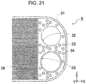
- FIG. 21 is an enlarged plan view of an end portion of the first heat transfer plate 30 that the plate heat exchanger 6 according to Embodiment 6 of the present disclosure includes.
- FIG. 22 is an enlarged plan view of an end portion of the second heat transfer plate 40 that the plate heat exchanger 6 according to Embodiment 6 of the present disclosure includes.
- FIG. 23 is an enlarged plan view illustrating a positional relationship between the first convexity 53 and the second convexity 63 in the plate heat exchanger 6 according to Embodiment 6 of the present disclosure. As illustrated in FIG.
- the first convexity 53 is provided in the immediate vicinity of the first fluid inflow/outflow hole 32 and the first passage hole 33 on the +X-end of the first heat transfer plate 30.
- the first convexity 53 in equal count is also provided in the immediate vicinity of the first fluid inflow/outflow hole 35 and the first passage hole 36 on the -X-end of the first heat transfer plate 30.
- the count of the second convexity 63 provided in the immediate vicinity of the second fluid inflow/outflow hole 43 and the second passage hole 42 on the +X-end of the second heat transfer plate 40 is lower than that of the first convexity 53 in order to lessen the impact on the increase in pressure loss due to the aforementioned channel resistor.
- the second convexities 63 are arranged at positions that are offset with respect to the first convexities 53 as viewed in the Y-direction.
- the second convexity 63 is also provided in the immediate vicinity of the second passage hole 45 and the second fluid inflow/outflow hole 46 on the -X-end of the second heat transfer plate 40.
- the plate heat exchanger 6 since dimples (although the term “dimples” typically refers to concavities, here “dimple-shaped” specifically refers to the first convexity 53 that is formed by the depressing of the -Y-surface of the first heat transfer plate 30 towards the +Y-side) are provided on the first fluid side in a concentrated manner, the negative impact they have on the overall performance of the heat pump hot water supply system 5 can be lessened.
- the adding of channel resistors promote mixing of the vapor and liquid, thereby enabling the first fluid in the two-phase state to be transitioned to more of a single-phase state.
- the gas/liquid fluid can be circulated in an even distribution.
- the average heat transfer coefficient on the refrigerant side can be improved over that in Embodiment 1.
- the tip of the flange 300 extends in the radial direction from the first tubular wall 34, 37.
- the flange 300 may be of any shape as long as joining to the first heat transfer plate 30 and the second heat transfer plate 40 can be achieved.
- FIG. 24 is a cross-sectional view of a modified example of the flange of the first tubular wall 34, 37.
- FIG. 25 is a cross-sectional view of a modified example of the first fluid supply pipe 12, the first fluid inflow/outflow hole 32, and the second passage hole 42.
- the flange 301 may extend from the +Y-end of the first tubular wall 34, 37 towards the inner side of the first passage hole 33, 36.
- the flange 301 may be provided on the second tubular wall 44, 47.
- the flange 301 provided on the second tubular wall 44, 47 may from the +Y-end of the second tubular wall 44, 47 towards the inner side of the second passage hole 42, 45.
- the flanges 300 and 301 that which is provided on the first heat transfer plate 30 may be referred to as the first flange and that which is provided on the second heat transfer plate 40 may be referred to as the second flange.
- the first inner fin 38 and the second inner fin 48 are formed in a shape that includes wave-like fin sections that have protuberances and interspaces in the Z-direction and extend in the X-direction.
- the first inner fin 38 and the second inner fin 48 in the present disclosure are not limited to this shape.
- the fin sections may be formed in any shape.
- FIG. 26 is a perspective view of the first inner fin 38 arranged on the first heat transfer plate 30 and the second inner fin 48 arranged on the second heat transfer plate 40 that the plate heat exchanger 1 according to Embodiment 1 of the present disclosure includes.
- FIGS. 26A, 26B, 26C , 26D, 26E, and 26F respectively illustrate an off-set type fin, a flat plate-type fin, a wave-type fin, a louver-type fin, a corrugated-type fin, and a pin-type fin.
- the fin sections of the first inner fin 38 and the second inner fin 48 may be off-set type fins in which the inner wall of the grooves illustrated in FIG. 26A alternatingly project outwardly.
- the fin sections may be flat plate-type fins that are multiple flat plates arranged parallel to one another as illustrated in FIG. 26B .
- the fin sections may be wave-type fins that are wave-shaped as viewed in plan view, louver-type fins, or corrugated-type fins respectively illustrated in FIGS. 26C , 26D, and 26E .
- the fin sections may be so-called pin-type fins in which pins are arrayed in a grid-shape as illustrated in FIG. 26F .
- the first convexities 50 to 53 and the second convexities 60 to 63 are cylindrically shaped.
- the first convexities 50 to 53 and the second convexities 60 to 63 may be any shape as long as they are formed as convexities that protrude from the plate surface of the first heat transfer plate 30 and the plate surface of the second heat transfer plate 40.
- FIGS. 27A, 27B, 27C , 27D, 27E and 27F are rear views of the X region illustrated in FIG. 8 .
- FIG. 27A a perspective view as viewed from the rear of the first convexity 50 that is described in Embodiment 1.
- FIGS. 27B, 27C , 27D, 27E, and 27F respectively illustrate the first convexity 50 as being wedge-shaped, elliptically-shaped, triangularly-shaped, square-shaped, and arc-shaped as viewed in the Y-direction.
- the first convexity 50 may be formed as wedge-shaped, elliptically-shaped, triangularly-shaped, square-shaped, or arc-shaped as viewed in the Y-direction.
- the first convexities 51 to 53 and the second convexities 60 to 63 likewise may be formed as wedge-shaped, elliptically-shaped, triangularly-shaped, square-shaped, or arc-shaped as viewed in the Y-direction.
- the tip of the wedge preferably is directed in the direction into which the first fluid and the second fluid flow. In this orientation, pressure loss of the first fluid and the second fluid can be reduced.
- the diameter of the first convexity 50 and the diameter of the second convexity 60 are 1/14 to 1/15 the diameter of the first fluid inflow/outflow hole 32.
- the first convexity 50 and the second convexity 60 may be any size.
- the first convexities 51 to 53 and the second convexities 61 to 63 also may be any size.
- FIG. 28 is an enlarged plan view illustrating a modified example of the first convexity 50 that the plate heat exchanger 1 according to Embodiment 1 of the present disclosure includes.
- FIG. 29 is an enlarged plan view illustrating another modified example of the first convexity 50 that the plate heat exchanger 1 according to Embodiment 1 of the present disclosure includes.
- the diameter of the first convexity 50 may be greater than that in Embodiment 1. In such a case, the count of the first convexity 50 may be less than that in Embodiment 1.
- the diameter of the first convexity 50 may be less than that in Embodiment 1.
- the count of the first convexities 50 may be greater than that in Embodiment 1.
- the size of the first convexity 50 as viewed in the Y-direction that is, the surface area of the of the first convexity 50 as viewed in the Y-direction may be modified in accordance with the count of the first convexity 50.
- the count and surface area of the first convexity 50 preferably are determined in accordance with the pressure resistance required for the laminate body 100. This likewise applied to the first convexities 51 to 53 and the second convexities 60 to 63.
- the plate heat exchanger 1 is used in the heat pump hot water supply system 5.
- the plate heat exchangers 1 to 4 are also applicable to chilling units for cooling.
- the plate heat exchangers 1 to 4 may be utilized with household appliances or industrial equipment such as power generation devices, foodstuffs-based heat sterilization processing devices, and the like. By using the plate heat exchangers 1 to 4 with such appliances, devices, or equipment, the heat exchange efficiency can be enhanced.
Abstract
Description
- The present disclosure relates to a plate heat exchanger and a heat pump hot water supply system.
- There is a plate heat exchanger that includes a configuration in which heat transfer plates are laminated together. Each of the heat transfer plates are formed with a channel for allowing fluid to flow.
- For example,
Patent Literature 1 discloses a plate heat exchanger that includes a configuration in which heat transfer plates, each including a channel and a fluid inflow/outflow hole that communicates with the channel and allows fluid to flow in and out, are laminated together. - In the plate heat exchanger described in
Patent Literature 1, a channel is formed with a recess and is rectangular in shape as viewed in plan view. Also, a fluid inflow/outflow hole is adjacent to the recess of the channel. Further, inner fins are arranged along the entirety of the recess of the channel. In doing so, the heat-exchange efficiency is high. -
PTL 1: International Publication No. WO 2008/023732 - In the plate heat exchanger described in
Patent Literature 1, the fluid inflow/outflow hole is adjacent to the recess of the channel. Therefore, the fluid easily flows to the portion of the inner fin that is adjacent to the inflow/outflow hole. However, the fluid cannot easily flow to other portions of the inner fins that are away from the inflow/outflow hole. As a result, the loss of pressure of the fluid is great along the entirety of the inner fins. As such, the heat exchange efficiency of the plate heat exchanger decreases. - In order to solve the aforementioned problems, an objective of the present disclosure is to provide a plate heat exchanger and a heat pump hot water supply system that have a high heat-exchange efficiency.
- In order to achieve the aforementioned objective a plate heat exchanger according to the present disclosure includes heat transfer plates that are laminated atop one another, each transfer plate including a plate portion in which an inflow/outflow hole is formed that causes a fluid to flow in and out, an outer circumferential wall portion that extends on one surface side of the plate portion and that defines a channel together with a plate portion adjacent to the one surface side for allowing the fluid to flow between the adjacent plate portions, and an inner fin that is attached to an inside portion of the channel. The inner fin is mounted at a position, spaced apart from an inflow/outflow hole inside the channel, on the one surface of the plate portion. The entire periphery of the inflow/outflow hole is in contact with space where the inner fin is not provided.
- According to the configuration of the present disclosure since the position where the inner fin is mounted on the one surface of the plate portion is a position that is spaced apart from the inflow/outflow hole inside the channel, the inner fin does not cover the inflow/outflow hole. Also, since the entire periphery of the inflow/outflow hole is in contact with space where the inner fin is not provided, there is sufficient space in the surrounding area of the inflow/outflow hole for fluid to flow. Since the fluid spreads out across the entirety of the channel because of the space where the inner fin is not disposed, the pressure loss of the fluid is low. As a result, heat exchange efficiency can be enhanced.
-
- FIG. 1
- is an exploded perspective view of a plate heat exchanger according to
Embodiment 1 of the present disclosure; - FIG. 2
- is a cross-sectional view taken along II-II illustrated in
FIG. 1 ; - FIG. 3
- is a cross-sectional view taken along III-III illustrated in
FIG. 1 ; - FIG. 4
- is a cross-sectional view taken along IV-IV illustrated in
FIG. 1 ; - FIG. 5
- is a front view of a first heat transfer plate that the plate heat exchanger according to
Embodiment 1 of the present disclosure includes; - FIG. 6
- is a cross-sectional view of a first passage hole formed in the first heat transfer plate and a second passage hole formed in a second heat transfer plate of the plate heat exchanger according to
Embodiment 1 of the present disclosure; - FIG. 7
- is a front view of the second heat transfer plate that the plate heat exchanger according to
Embodiment 1 of the present disclosure includes; - FIG. 8
- is an enlarged plan view of an end portion of the first heat transfer plate that the plate heat exchanger according to
Embodiment 1 of the present disclosure includes; - FIG. 9A
- is a perspective view illustrating an IX region illustrated in
FIG. 8 as viewed from the front; - FIG. 9B
- is a perspective view illustrating the IX region illustrated in
FIG. 8 as viewed from the rear; - FIG. 10
- is an enlarged plan view illustrating an end portion of the second heat transfer plate that the plate heat exchanger according to
Embodiment 1 of the present disclosure includes; - FIG. 11
- is an enlarged plan view illustrating a positional relationship between a first convexity and a second convexity in the plate heat exchanger according to
Embodiment 1 of the present disclosure; - FIG. 12
- is cross-sectional view of a first fluid supply pipe, a first fluid inflow/outflow hole, and a second passage hole formed in the plate heat exchanger according to
Embodiment 1 of the present disclosure; - FIG. 13
- is an enlarged plan view of an end portion of a first heat transfer plate that a plate heat exchanger according to
Embodiment 2 of the present disclosure includes; - FIG. 14
- is an enlarged plan view of an end portion of a second heat transfer plate that the plate heat exchanger according to
Embodiment 2 of the present disclosure includes; - FIG. 15
- is an enlarged plan view illustrating a positional relationship between a first convexity and a second convexity in the plate heat exchanger according to
Embodiment 2 of the present disclosure; - FIG. 16
- schematic cross-sectional view of a first fluid supply pipe and a second fluid supply pipe of the plate heat exchanger according to
Embodiment 2 of the present disclosure; - FIG. 17
- is an enlarged plan view of an end portion of a second heat transfer plate that a plate heat exchanger according to
Embodiment 3 of the present disclosure includes; - FIG. 18
- is a schematic cross-sectional view of a first fluid supply pipe and a second fluid supply pipe of the plate heat exchanger according to
Embodiment 3 of the present disclosure; - FIG. 19
- is an enlarged cross-sectional view of a laminate body of a plate heat exchanger according to
Embodiment 4 of the present disclosure; - FIG. 20
- is a block diagram of a heat pump hot water supply system according to
Embodiment 5 of the present disclosure; - FIG. 21
- is an enlarged plan view of an end portion of a first heat transfer plate that a plate heat exchanger according to
Embodiment 6 of the present disclosure includes; - FIG. 22
- is an enlarged plan view of an end portion of a second heat transfer plate that the plate heat exchanger according to
Embodiment 6 of the present disclosure includes; - FIG. 23
- is an enlarged plan view illustrating a positional relationship between a first convexity and a second convexity in the plate heat exchanger according to
Embodiment 6 of the present disclosure; - FIG. 24
- is a cross-sectional view of a modified example of a flange of a first tubular wall of the plate heat exchanger according to
Embodiment 1 of the present disclosure; - FIG. 25
- is cross-sectional view of a modified example the first fluid supply pipe, the first fluid inflow/outflow hole, and the second passage hole of the plate heat exchanger according to
Embodiment 1 of the present disclosure; - FIG. 26A
- is a perspective view of off-set type first inner fins arranged on the first heat transfer plate and off-set type second inner fins arranged on the second heat transfer plate that the plate heat exchanger according to
Embodiment 1 of the present disclosure includes; - FIG. 26 B
- is a perspective view of flat plate-type first inner fins arranged on the first heat transfer plate and flat plate-type second inner fins arranged on the second heat transfer plate that the plate heat exchanger according to
Embodiment 1 of the present disclosure includes; - FIG. 26C
- is a perspective view of wave-type first inner fins arranged on the first heat transfer plate and wave-type second inner fins arranged on the second heat transfer plate that the plate heat exchanger according to
Embodiment 1 of the present disclosure includes; - FIG. 26D
- is a perspective view of louver-type first inner fins arranged on the first heat transfer plate and louver-type second inner fins arranged on the second heat transfer plate that the plate heat exchanger according to
Embodiment 1 of the present disclosure includes; - FIG. 26E
- is a perspective view of corrugated-type first inner fins arranged on the first heat transfer plate and corrugated-type second inner fins arranged on the second heat transfer plate that the plate heat exchanger according to
Embodiment 1 of the present disclosure includes; - FIG. 26F
- is a perspective view of pin-type first inner fins arranged on the first heat transfer plate and pin-type second inner fins arranged on the second heat transfer plate that the plate heat exchanger according to
Embodiment 1 of the present disclosure includes; - FIG. 27A
- is a rear view of an X region illustrated in
FIG. 8 with the first convexity being circularly-shaped; - FIG. 27B
- is a rear view of the X region illustrated in
FIG. 8 with the first convexity being wedge-shaped; - FIG. 27C
- is a rear view of the X region illustrated in
FIG. 8 with the first convexity being elliptically-shaped; - FIG. 27D
- is a rear view of the X region illustrated in
FIG. 8 with the first convexity being triangularly-shaped; - FIG. 27E
- is a rear view of the X region illustrated in
FIG. 8 with the first convexity being square-shaped; - FIG. 27F
- is a rear view of the X region illustrated in
FIG. 8 with the first convexity being arc-shaped - FIG. 28
- is an enlarged plan view of a modified example of the first convexity that the plate heat exchanger according to
Embodiment 1 of the present disclosure includes; and - FIG. 29
- is an enlarged plan view of another modified example of the first convexity that the plate heat exchanger according to
Embodiment 1 of the present disclosure includes. - A plate heat exchanger and a heat pump hot water supply system according one or more embodiments of the present disclosure are described in detail with reference the drawings. Throughout the drawings, the same or equivalent components are denoted by the same reference signs. With the orthogonal XYZ-coordinate system in each figure, X-axis represents the lateral direction, Z-axis represents the vertical direction, and Y-axis represents the direction orthogonal to the X- and Z-axes of the plate heat exchanger. This coordinate system is referred to hereafter as appropriate.
- A plate heat exchanger according to
Embodiment 1 is a plate heat exchanger in which a first heat transfer plate formed with a channel for allowing a fluid to flow and a second heat transfer plate formed with a channel for allowing another fluid to flow are laminated together such that heat exchange is performed between the two fluids. In this plate heat exchanger, space is provided on the surrounding area of each fluid inflow/outflow hole formed in the channels in order to make it easy for fluids to flow to the channels of the first heat transfer plate and the second heat transfer plate. Also, since fluid flows through this space to the inner fins provided in the channels, pressure loss in this plate heat exchanger is low. The configuration of the plate heat exchanger is described with reference toFIGS. 1 to 4 . In the description below, the two fluids are individually referred to as the first fluid and the second fluid. -
FIG. 1 is an exploded perspective view of aplate heat exchanger 1 according toEmbodiment 1 of the present disclosure.FIG. 2 is a cross-sectional view taken along II-II illustrated inFIG. 1 .FIG. 3 is a cross-sectional view taken along III-III illustrated inFIG. 1 .FIG. 4 is a cross-sectional view taken along IV-IV illustrated inFIG. 1 . InFIGS. 2 to 4 , some firstheat transfer plates 30 and secondheat transfer plates 40 among the firstheat transfer plates 30 and the secondheat transfer plates 40 are omitted.
As illustrated inFIGS. 1 to 4 , aplate heat exchanger 1 according toEmbodiment 1 includes alaminate body 100 in which the firstheat transfer plates 30 individually formed with a channel for allowing the first fluid to flow and the secondheat transfer plates 40 individually formed with a channel for allowing the second fluid that causes heat exchange with the first fluid to flow are alternatingly laminated atop one another. Thelaminate body 100 is reinforced by being sandwiched between afirst reinforcement plate 10 and asecond reinforcement plate 20. - Of the configurations of the
plate heat exchanger 1, a configuration of thefirst reinforcement plate 10 and thesecond reinforcement plate 20 is described first. Then, a configuration of the firstheat transfer plate 30 and the secondheat transfer plate 40 is described. - The
first reinforcement plate 10 is a plate that reinforces thelaminate body 100. Connection pipes for supplying and discharging the first fluid and the second fluid that flows to thelaminate body 100 are connected to thefirst reinforcement plate 10. Thefirst reinforcement plate 10, as illustrated inFIG. 1 , is rectangular in shape and has rounded corners. Also, thefirst reinforcement plate 10 is parallel with XZ plane and is placed on the +Y-most side in theplate heat exchanger 1. Thefirst reinforcement plate 10 is provided with a first reinforcement outercircumferential wall portion 11 that surrounds the outer circumference of thefirst reinforcement plate 10. The first reinforcement outercircumferential wall portion 11, as illustrated inFIG. 2 and FIG. 3 , is joined to a second outercircumferential wall portion 41 that the secondheat transfer plate 40 positioned at the +Y-most position within thelaminate body 100 includes. The second outercircumferential wall portion 41 is described further below. Also, the first reinforcement outercircumferential wall portion 11 is inclined to the outside of thefirst reinforcement plate 10 as the first reinforcement outercircumferential wall portion 11 extends to the +Y-side from the rim of thefirst reinforcement plate 10. - Also, the +X-end of the
first reinforcement plate 10, as illustrated inFIG. 1 , is provided with a firstfluid supply pipe 12 and secondfluid supply pipe 13 for respectively supplying the first fluid and the second fluid to thelaminate body 100. The firstfluid supply pipe 12 and the secondfluid supply pipe 13 are aligned side-by-side in the Z-direction and extend into the +Y-direction. Here, the firstfluid supply pipe 12 and the secondfluid supply pipe 13 are individually connected to non-illustrated connection pipes for the respectively supplying the first fluid and the second fluid. The first fluid and the second fluid are respectively supplied to the firstfluid supply pipe 12 and the secondfluid supply pipe 13 via these connection pipes. In the firstfluid supply pipe 12, the first fluid flows in the direction indicated by arrow F and in the secondfluid supply pipe 13, the second fluid flows in the direction indicated by arrow S. - The -X-end of the
first reinforcement plate 10 is provided with a firstfluid discharge pipe 14 and a secondfluid discharge pipe 15 for respectively discharging the first fluid and the second fluid from thelaminate body 100. The firstfluid discharge pipe 14 and the secondfluid discharge pipe 15 are formed to be the same in shape as the aforementioned firstfluid supply pipe 12 and the secondfluid supply pipe 13. The firstfluid discharge pipe 14 and the secondfluid discharge pipe 15 are aligned side-by-side in the Z-direction and extend into the +Y-direction. The firstfluid discharge pipe 14 and the secondfluid discharge pipe 15 are individually connected to non-illustrated connection pipes for respectively discharging the first fluid and the second fluid. In the firstfluid discharge pipe 14 and the secondfluid discharge pipe 15, the first fluid and the second fluid are discharged to the respective connection pipes. - The
second reinforcement plate 20 is a plate for reinforcing thelaminate body 100, and unlike thefirst reinforcement plate 10, is without a portion for connecting to the connection pipes of the first fluid and the second fluid. Thesecond reinforcement plate 20 is formed to have a rectangular shape with the same external appearance as thefirst reinforcement plate 10. Thesecond reinforcement plate 20 is placed parallel to thefirst reinforcement plate 10. Also, thesecond reinforcement plate 20 is placed on the -Y-most end in theplate heat exchanger 1, and, together with thefirst reinforcement plate 10 sandwiches thelaminate body 100. Thesecond reinforcement plate 20 is provided with a second reinforcement outercircumferential wall portion 21 that surrounds the outer circumference of thesecond reinforcement plate 20 and inclines to the outside of this outer circumference. The second reinforcement outercircumferential wall portion 21 is for joining to the first outercircumferential wall portion 31 of the firstheat transfer plate 30 that is positioned on the -Y-most side of the sandwichedlaminate body 100. The shape of the second reinforcement outercircumferential wall portion 21 is the same as that of the first reinforcement outercircumferential wall portion 11. - Next, the first
heat transfer plate 30 and the secondheat transfer plate 40 of theaforementioned laminate body 100 are described with reference toFIGS. 5 to 7 . -
FIG. 5 is a front view of the firstheat transfer plate 30.FIG. 6 is a cross-sectional view of afirst passage hole heat transfer plate 30 and asecond passage hole heat transfer plate 40.FIG. 7 is a front view of the secondheat transfer plate 40. The firstheat transfer plate 30 is a member for allowing the first fluid to flow within theplate heat exchanger 1. The firstheat transfer plate 30, as illustrated inFIG. 5 , includes aplate portion 39 and the first outercircumferential wall portion 31 that surrounds the outer circumference of theplate portion 39. - The
plate portion 39 is rectangular in shape and has rounded corners. The shape and size of theplate portion 39 are the same as the aforementionedfirst reinforcement plate 10 and thesecond reinforcement plate 20. - The first outer
circumferential wall portion 31, as illustrated inFIGS. 2 to 4 , extends from the outer circumference of theplate portion 39 to the +Y-side. Also, the first outercircumferential wall portion 31 is inclined to the outside of theplate portion 39 as the first outercircumferential wall portion 31 extends to the +Y-side. The +Y-end of the first outercircumferential wall portion 31 is in contact with a second outercircumferential wall portion 41 that the secondheat transfer plate 40 positioned on the +Y-side with respect to theplate portion 39 includes. The second outercircumferential wall portion 41 is described further below. In doing so, the +Y-side of the space formed by the first outercircumferential wall portion 31 surrounding theplate portion 39 is closed. In thelaminate body 100, a plurality of spaces surrounded in such a manner by the first outercircumferential wall portions 31 are formed. - In order to cause the first fluid to flow between the spaces surrounded by the aforementioned first outer
circumferential wall portions 31, the side on the +X-end and the side on the -X-end of theplate portion 39, as illustrated inFIG. 5 , have first fluid inflow/outflow holes 32 and 35 for causing the first fluid to flow in and out. As described further below, the secondheat transfer plate 40 also has a space that is defined by the second outercircumferential wall portion 41 surrounding theplate portion 49. In order to cause the second fluid to flow to the space formed in this secondheat transfer plate 40, the +X-end side and the -X-end side of theplate portion 39 have first passage holes 33 and 36 through which the second fluid flows in and out. - The first fluid inflow/outflow holes 32, 35 are round holes that pass through the first
heat transfer plate 30 in the Y-direction. The first fluid inflow/outflow holes 32 and 35 both have the same inner diameter. The first fluid inflow/outflow holes 32, 35 in thelaminate body 100 illustrated inFIG. 2 , are formed at positions that respectively align with the firstfluid supply pipe 12 and the firstfluid discharge pipe 14 of thefirst reinforcement plate 10 as viewed in the Y-direction. - The first passage holes 33, 36 are round holes that pass through the first
heat transfer plate 30 in the Y-direction, and both have an inner diameter that is the same as that of the first fluid inflow/outflow holes 32, 35. The first passage holes 33, 36 are arranged in the -Z-side with respect to the first fluid inflow/outflow holes 32, 35. Also, the first passage holes 33, 36, as illustrated inFIG. 3 , are formed at positions that respectively align with secondfluid supply pipe 13 and the secondfluid discharge pipe 15 of thefirst reinforcement plate 10 as viewed in the Y-direction. Also, thefirst passage hole tubular wall first passage hole outflow hole heat transfer plate 40. On the +Y-end of the firsttubular wall FIG. 6 , aflange 300 extending in the radial direction from the firsttubular wall plate portion 49 of the secondheat transfer plate 40. InFIG. 1 andFIGS. 2 to 5 , the firsttubular wall flange 300 to ease understanding. - The second
heat transfer plate 40 is a member for allowing the second fluid to flow within theplate heat exchanger 1. The secondheat transfer plate 40, similarly to the firstheat transfer plate 30, includes theplate portion 49 and the second outercircumferential wall portion 41 that surrounds the outer circumference of theplate portion 49 as illustrated inFIG. 7 . - The
plate portion 49 is formed to have the same shape and size as that of theplate portion 39 of the firstheat transfer plate 30. Also, the second outercircumferential wall portion 41 is formed to have the same shape and size as that of the first outercircumferential wall portion 31 of the firstheat transfer plate 30. Also, the +Y-end of the second outercircumferential wall portion 41, as illustrated inFIGS. 2 to 4 , is in contact with either the first reinforcement outercircumferential wall portion 11 that thefirst reinforcement plate 10 positioned on the +Y-side with respect to theplate portion 49 includes or the first outercircumferential wall portion 31 that the firstheat transfer plate 30 positioned on the +Y-side with respect to theplate portion 49 includes. As a result, the +Y-side of the space formed by the second outercircumferential wall portion 41 surrounding the outer circumference of theplate portion 49 is closed by theplate portion 10 or the firstheat transfer plate 30. In thelaminate body 100, a plurality of spaces surrounded in such a manner by the second outercircumferential wall portions 41 are formed. - In order to cause the second fluid to flow between the spaces surrounded by the aforementioned second outer
circumferential wall portions 41, the +X-end side and the -X-end side of theplate portion 49, as illustrated inFIG. 7 , have second fluid inflow/outflow holes 43 and 46 for causing the second fluid to flow in and out. Also, in order to cause the first fluid to flow in the aforementioned space that is formed by being surrounded by the first outercircumferential wall portion 31 of the firstheat transfer plate 30, the +X-end side and the -X-end side of theplate portion 49 have second passage holes 42, 45 through which the first fluid flows in and out. - The second fluid inflow/outflow holes 43, 46 are round holes that pass through the
plate portion 49. The second fluid inflow/outflow holes 43, 46 both have the same inner diameter as the first passage holes 33, 36. Also, the second fluid inflow/outflow holes 43, 46, as illustrated inFIG. 3 , are formed as positions that respectively align with the secondfluid supply pipe 13 and the secondfluid discharge pipe 15 of thefirst reinforcement plate 10 as viewed in the Y-direction. In doing so, in a case in which the second fluid is supplied from the secondfluid supply pipe 13 into thelaminate body 100, the second fluid at the second fluid inflow/outflow hole 43 flows smoothly into the Y-direction via thefirst passage hole 33, which is aligned as viewed in the Y-direction. Also, at the second fluid inflow/outflow hole 46, the second fluid flows via thefirst passage hole 36, into the Y-direction, that is to the secondfluid discharge pipe 15. - Also, the second passage holes 42, 45 are round holes that pass through the
plate portion 49. The second passage holes 42, 45 both have the same inner diameter as the first fluid inflow/outflow holes 32, 35. The second passage holes 42, 45, as illustrated inFIG. 2 , are formed at positions that respectively align with the firstfluid supply pipe 12 and the firstfluid discharge pipe 14 of thefirst reinforcement plate 10 as viewed in the Y-direction. Also, thesecond passage hole tubular wall second passage hole fluid supply pipe 12, the firstfluid discharge pipe 14, and the first fluid inflow/outflow hole fluid supply pipe 12, the first fluid at thesecond passage hole 42 flows into the first fluid inflow/outflow hole 32 that is in the Y-direction. At thesecond passage hole 45, the first fluid flows to the first fluid inflow/outflow hole 35 and the firstfluid discharge pipe 14, which are aligned as viewed in the Y-direction. On the secondtubular wall FIG. 6 , aflange 300 that has the same shape as that of the firsttubular wall plate portion 39 of the firstheat transfer plate 30. InFIGS. 1 to 4 andFIG. 7 , the secondtubular wall flange 300 to ease understanding. - In order to enhance heat exchange efficiency between the first fluid and the second fluid supplied, a first
inner fin 38 and a secondinner fin 48 are respectively arranged on the X-direction-intermediate portion of the firstheat transfer plate 30 and the X-direction intermediate portion of the secondheat transfer plate 40, as illustrated inFIG. 5 andFIG. 7 . Also, in order to preventlaminate body 100 deformation caused by the supplied first fluid and the second fluid, afirst convexity 50 and asecond convexity 60, which are not illustrated inFIG. 5 andFIG. 7 , are respectively provided on the firstheat transfer plate 30 and the secondheat transfer plate 40. Next, the firstinner fin 38, the secondinner fin 48, thefirst convexity 50, and thesecond convexity 60 are described. -
FIG. 8 is an enlarged plan view of an end portion of the firstheat transfer plate 30.FIGS. 9A and 9B are perspective views of IX region illustrated inFIG. 8 .FIG. 10 is an enlarged plan view of an end portion of the secondheat transfer plate 40.FIG. 11 is an enlarged plan view illustrating the positions of thefirst convexity 50 and thesecond convexity 60.
FIG. 9A is perspective view illustrating thefirst convexity 50 as viewed from the front andFIG. 9B is a perspective view illustrating thefirst convexity 50 as viewed from the rear.
The firstinner fin 38 and the secondinner fin 48, as illustrated inFIG. 8 andFIG. 10 , as illustrated inFIG. 8 andFIG. 10 each have a wave-like fin sections that have protuberances and interspaces in the Z-direction and extend in the X-direction. Thus, in a case in which the first fluid flows into the X-direction at the firstinner fin 38 and the second fluid flows into the X-direction at the secondinner fin 48, the first fluid and the second fluid flow along the respective fin sections. The heat of the first fluid and the second fluid transfers in the fin sections of the firstinner fin 38 and the secondinner fin 48, and as a result, heat exchange occurs between the first fluid and the second fluid. - The aforementioned wave-like fin sections are fixed to respective non-illustrated base portions of the first
inner fin 38 and the secondinner fin 48. Although not illustrated, the base portions are rectangular in shape as viewed in XZ plan view. Here, in the firstinner fin 38, the length of the base portion in the transverse direction is equal to the distance from the first outercircumferential wall portion 31 on the +Z-end of the firstheat transfer plate 30 to the first outercircumferential wall portion 31 on the -Z-end of the firstheat transfer plate 30. The length of the base portion in the longitudinal direction is less than the distance from the first fluid inflow/outflow hole 32 to the first fluid inflow/outflow hole 35 in the X-direction. Also, in the secondinner fin 48, the length of the base portion in the transverse direction is equal to the distance from the second outercircumferential wall portion 41 on the +Z-end of the secondheat transfer plate 40 to the second outercircumferential wall portion 41 on the -Z-end of the secondheat transfer plate 40. The length of the base portion in the longitudinal direction is less than the distance from the second fluid inflow/outflow hole 43 to the second fluid inflow/outflow hole 46 in the X-direction. Also, in both the firstinner fin 38 and the secondinner fin 48, the transverse direction of the base portion is directed in the Z-direction whereas the longitudinal direction of the base portion is directed in the X-direction. - The first
inner fin 38 and the secondinner fin 48, as illustrated inFIGS. 1 to 3 ,FIG. 5 ,FIG. 7 ,FIG. 8 , andFIG. 10 , are respectively mounted on the +Y-surface of firstheat transfer plate 30 and the +Y-surface of the secondheat transfer plate 40. The +X-end of the firstinner fin 38 and the +X-end of the secondinner fin 48 are respectively spaced apart from the first fluid inflow/outflow hole 32 and the second fluid inflow/outflow hole 43 in order to make it easier for the first fluid and the second fluid to flow in and out. In doing so, in a case in which the first fluid and second fluid respectively flow from the first fluid inflow/outflow hole 32 and the second fluid inflow/outflow hole 43 in the direction of the firstinner fin 38 and the secondinner fin 48, the first fluid and the second fluid can easily spread out in the Z-direction. As a result, the first fluid and the second fluid can easily flow evenly along the entirety of the firstinner fin 38 and the secondinner fin 48 in the Z-direction. Also, since there is space around the entire periphery of the first fluid inflow/outflow hole 32 and the entire periphery of the second fluid inflow/outflow hole 43 where the firstinner fin 38 and the secondinner fin 48 are not provided, the first fluid and the second fluid can respectively spread out easily to the surrounding areas of the first fluid inflow/outflow hole 32 and the second fluid inflow/outflow hole 43. - Also, the -X-end of the first
inner fin 38 and the -X-end of the secondinner fin 48 are respectively spaced apart from the first fluid inflow/outflow hole 35 and the second fluid inflow/outflow hole 46. Therefore, there is also space around the entire periphery of the first fluid inflow/outflow hole 35 and the entire periphery of the second fluid inflow/outflow hole 46 where the firstinner fin 38 and the secondinner fin 48 are not arranged. Thus, the first fluid and the second fluid can easily respectively flow from the firstinner fin 38 and the secondinner fin 48 into the first fluid inflow/outflow hole 35 and the second fluid inflow/outflow hole 46. For ease of flow of the first fluid and the second fluid, the distance at which the firstinner fin 38 and the first fluid inflow/outflow hole 35 are spaced apart and the distance at which the secondinner fin 48 and the second fluid inflow/outflow hole 46 are spaced apart are both preferably are 1/20 to 1/4 the diameter of the first fluid inflow/outflow hole 35 (the second fluid inflow/outflow hole 46). Even more preferably, these distances are 1/16 to 1/8 the diameter of the first fluid inflow/outflow hole 35 (the second fluid inflow/outflow hole 46). Also, it is preferable that these distances be larger than the pitch between the waves in the X-direction of the wave-like fin sections that the firstinner fin 38 and the secondinner fin 48 include or the pitch between fin sections adjacent to each other in the Z-direction that the firstinner fin 38 and the secondinner fin 48 include. Specifically, it is preferable that these distances be 1.5 to 2.0 times greater than these pitches. The distance at which the firstinner fin 38 and the first fluid inflow/outflow hole 32 are spaced apart and the distance at which the secondinner fin 48 and the second fluid inflow/outflow hole 43 are spaced apart are the same. - No structure is provided between the first
inner fin 38 and the first fluid inflow/outflow hole 35 or between the secondinner fin 48 and the second fluid inflow/outflow hole 46. Likewise, no structure is provided between the firstinner fin 38 and the first fluid inflow/outflow hole 32 or between the secondinner fin 48 and the second fluid inflow/outflow hole 43. As such, thelaminate body 100 is susceptible to deformation due to being low in strength in certain regions. Therefore, the aforementionedfirst convexity 50 and thesecond convexity 60 are arranged between these inner fins and inflow/outflow holes in order to preserve the shape of thelaminate body 100 and maintain the state in which the first fluid and the second fluid can flow through smoothly. - The
first convexity 50 arranged between the firstinner fin 38 and the first fluid inflow/outflow hole 35 includes a configuration that is similar to thefirst convexity 50 arranged between the firstinner fin 38 and the first fluid inflow/outflow hole 32. Also, thesecond convexity 60 arranged between the secondinner fin 48 and the second fluid inflow/outflow hole 46 includes a configuration that is similar to thesecond convexity 60 that is arranged between the secondinner fin 48 and the second fluid inflow/outflow hole 43. Therefore, thefirst convexity 50 arranged between the firstinner fin 38 and the first fluid inflow/outflow hole 32 and thesecond convexity 60 arranged between the secondinner fin 48 and the second fluid inflow/outflow hole 43 are described as examples. - As illustrated in
FIG. 8 , multiplefirst convexities 50 are arranged in the region on the first fluid inflow/outflow hole 32-side of the firstinner fin 38, that is, on the +X region of the firstheat transfer plate 30. The individual positions of thesefirst convexities 50 are random in order to expand the flow of the first fluid. Each of thefirst convexities 50 protrude from the +Y-side of theplate portion 39 of the firstheat transfer plate 30 toward the +Y-side. - Each of the
first convexities 50, as illustrated inFIGS. 9A and 9B , are formed to have a tip, that is, a cylindrical shape whose +Y-end is closed. The diameter of thefirst convexity 50 is 1/14 to 1/15 the diameter of the first fluid inflow/outflow hole 32. Also, the diameter of thefirst convexity 50 preferably is less than the distance at which the firstinner fin 38 and the first fluid inflow/outflow hole 35 spaced apart and less than the distance at which the secondinner fin 48 and the second fluid inflow/outflow hole 46 are spaced apart. Specifically, the diameter of thefirst convexity 50 is 2/3 to 1/3 these distances. Also, thefirst convexity 50 is formed to have a height at which the +Y-end thereof abuts against the -Y-surface of the secondheat transfer plate 40, while in a state in which the firstheat transfer plates 30 and the secondheat transfer plates 40 together form the laminate body 100 (hereinafter referredlaminate body 100 in a formed state). Thus, with thelaminate body 100 is a formed state, thefirst convexity 50 maintains the shape of the channel through which the first fluid flows, serving as a support column between the secondheat transfer plate 40 and the firstheat transfer plate 30. - Also, as illustrated in
FIG. 10 , multiplesecond convexities 60 are arranged in the region on the second fluid inflow/outflow hole 43-side of the secondinner fin 48, that is, on the +X region of the secondheat transfer plate 40. Although not illustrated, thesecond convexity 60 is formed to have a height at which the +Y-end thereof abuts against the -Y-surface of the firstheat transfer plate 30, while in a state in which the firstheat transfer plates 30 and the secondheat transfer plates 40 together form thelaminate body 100. Thus, with thelaminate body 100 in the formed state, thesecond convexity 60 maintains the shape of the channel through which the second fluid flows, serving as a support column between the firstheat transfer plate 30 and the secondheat transfer plate 40. Also, as illustrated inFIG. 11 , with thelaminate body 100 in a formed state, thesecond convexities 60 are arranged at positions that do not overlap with thefirst convexities 50 as viewed in the Y-direction, that is, are arranged randomly yet such that the first convexities 50 andsecond convexities 60 are offset from one another. - Next, the flow of the first fluid and the second fluid in the
plate heat exchanger 1 is described with reference toFIG. 12 . In the description provided below, it is taken that the first fluid and the second fluid that are targets for heat exchange are respectively provided to the firstfluid supply pipe 12 and the secondfluid supply pipe 13 by connecting, to theplate heat exchanger 1, connection pipes that are for supplying the first fluid and the second fluid. It is also taken that the first fluid and the second fluid that underwent heat exchange are respectively discharged from the firstfluid discharge pipe 14 and the secondfluid discharge pipe 15 by connecting, to theplate heat exchanger 1, connection pipes that are for discharging the first fluid and the second fluid. Also, the description provided below is provided with reference back toFIG. 1 as necessary. -
FIG. 12 is a cross-sectional view of the firstfluid supply pipe 12, the first fluid inflow/outflow hole 32 and thesecond passage hole 42. First, the flow of the first fluid is described. The first fluid is externally supplied to thelaminate body 100 via the firstfluid supply pipe 12. The supplied first fluid, as illustrated inFIG. 12 , flows through thesecond passage hole 42 of the secondheat transfer plate 40 and the first fluid inflow/outflow hole 32 of the firstheat transfer plate 30 in the direction of arrow F, that is, in the -Y direction. Here, the secondtubular wall 44 is formed in thesecond passage hole 42. In contrast to this, there is no tubular wall surrounding the outer circumference of the first fluid inflow/outflow hole 32. Therefore, the first fluid flows not only in the -Y-direction but also from the first fluid inflow/outflow hole 32 into the direction towards the first inner fin 38-side (that is, in the direction of arrow F1). Thus, the first fluid flows along the +Y-surface of the firstheat transfer plate 30. The +Y-surface of the firstheat transfer plate 30 is provided in a space where only thefirst convexity 50 exists between the first fluid inflow/outflow hole 32 and the firstinner fin 38. Within this space, the first fluid enters the first fluid inflow/outflow hole 32 and spreads out across the entirety of the firstheat transfer plate 30 in the Z-direction, flowing into the firstinner fin 38 in an even distribution. - The first fluid that flowed into the first
inner fin 38 undergoes heat exchange with firstinner fin 38. The first fluid, having undergone heat exchange, then flows to the non-illustrated first fluid inflow/outflow hole 35-side of the non-illustrated firstheat transfer plate 30. The immediate vicinity of the first fluid inflow/outflow hole 35 extends to the firstinner fin 38. The space in this immediate vicinity includes nothing but thefirst convexity 50. Therefore, pressure loss of the first fluid is low in this space. As a result, the first fluid flows smoothly to the first fluid inflow/outflow hole 35-side. At the first fluid inflow/outflow hole 35-side, the -X-end of the firstheat transfer plate 30 is closed by the first outercircumferential wall portion 31. In contrast to this, a portion of the plate surface of the firstheat transfer plate 30 is open because of the first fluid inflow/outflow hole 35. Therefore, the first fluid flows to the first fluid discharge pipe 14-side via the first fluid inflow/outflow hole 35. That is, the first fluid flows to thesecond passage hole 45 of the secondheat transfer plate 40 that is positioned on the +Y-side. Then the first fluid flows into the firstfluid discharge pipe 14 via thesecond passage hole 45 and discharges to the outside. - Next, the flow of the second fluid is described. The second fluid, as illustrated by arrow S in
FIG. 1 , is externally supplied to thelaminate body 100 via the secondfluid supply pipe 13. The supplied second fluid flows in the -Y-direction via the second fluid inflow/outflow hole 43 of the secondheat transfer plate 40 and thefirst passage hole 33 of the firstheat transfer plate 30. Here, the firsttubular wall 34 is formed in thefirst passage hole 33. In contrast to this, there is no tubular wall surrounding the outer circumference of the second fluid inflow/outflow hole 43. Therefore, the second fluid flows not only in the -Y-direction but also from the second fluid inflow/outflow hole 43 into the direction towards the second inner fin 48-side. Also, the second fluid flows along the +Y-surface of the secondheat transfer plate 40 and into the secondinner fin 48. - The second fluid that flowed into the second
inner fin 48 undergoes heat exchange with the secondinner fin 48. Thereafter, the second fluid flows from the secondinner fin 48 to the second fluid inflow/outflow hole 46. Since the space provided between the secondinner fin 48 and the second fluid inflow/outflow hole 46 includes nothing but thesecond convexity 60, the second fluid flows to the second fluid inflow/outflow hole 46-side with little pressure loss. On the second fluid inflow/outflow hole 46-side, the +Y-end of the secondheat transfer plate 40 is closed by the second outercircumferential wall portion 41. In contrast to this, a portion of the plate surface of the secondheat transfer plate 40 is open because of the second fluid inflow/outflow hole 46. Therefore, the second fluid flows to the second fluid discharge pipe 15-side via the second fluid inflow/outflow hole 46. That is, the second fluid flows to thefirst passage hole 36 of the firstheat transfer plate 30 that is positioned on the +Y-side or the secondfluid discharge pipe 15 positioned on the +Y-side. Then, the second fluid flows through the secondfluid discharge pipe 15 and discharges to the outside. - The heat that is transferred to the first
inner fin 38 and the secondinner fin 48 in turn respectively transfers to the firstheat transfer plate 30 and the secondheat transfer plate 40. Since the firstheat transfer plates 30 and the secondheat transfer plates 40 are alternately laminated atop one another, the heat transferred to the firstheat transfer plate 30 and the secondheat transfer plate 40 undergoes heat exchange between the firstheat transfer plate 30 and the secondheat transfer plate 40. As a result, the first fluid and the second fluid undergo heat exchange within theplate heat exchanger 1. - As described above, in the
plate heat exchanger 1 according toEmbodiment 1 of the present disclosure, the firstinner fin 38 is spaced apart from the first fluid inflow/outflow holes 32, 35. Also, the secondinner fin 48 is spaced apart from the second fluid inflow/outflow holes 43, 46. Also, the entire periphery of the first fluid inflow/outflow hole inner fin 38 is not provided and the entire periphery of the second fluid inflow/outflow hole inner fin 48 is not provided. Therefore, in the space between the firstinner fin 38 and the first fluid inflow/outflow hole inner fin 38, but instead spreads across the entirety of the firstinner fin 38. Also, in the space between the secondinner fin 48 and the second fluid inflow/outflow hole inner fin 48, but instead spreads across the entirety of the secondinner fin 48. As a result, in theplate heat exchanger 1, the pressure loss of the first fluid and the second fluid is low. - The
first convexity 50 is provided between the firstinner fin 38 and the first fluid inflow/outflow hole second convexity 60 is provided between the secondinner fin 48 and the second fluid inflow/outflow hole second convexity 60 is an offset position with respect to thefirst convexity 50 as viewed in the Y-direction. Therefore, thelaminate body 100 in theplate heat exchanger 1 does not easily deform due to the pressure of the first fluid and the second fluid. As a result, an increase in pressure loss due to deformation of thelaminate body 100 can be prevented. Also, thefirst convexity 50 and thesecond convexity 60 are provided at positions offset from each other as viewed in the Y-direction. Therefore, due to the first convexities 50 and thesecond convexities 60, the firstheat transfer plate 30 and the secondheat transfer plate 40 are reinforced by different portions as viewed in the Y-direction. As a result, the strength of theplate heat exchanger 1 can be further enhanced compared with a case in which thefirst convexity 50 and thesecond convexity 60 are placed in equal quantities in the same positions with respect to one another as viewed in the Y-direction. Specifically, the case in which thefirst convexity 50 and thesecond convexity 60 are arranged offset with respect to each other as viewed in the Y-direction is more effective for securing a compressive strength required to withstand the pressure of the fluid flowing through than the cases in which thefirst convexity 50 and thesecond convexity 60 are arranged in the same positions or in overlapping positions as viewed in the Y-direction. Also, since compressive strength can be secured using thefirst convexity 50 and thesecond convexity 60 in low quantities, pressure loss of the fluid cause by thefirst convexity 50 and thesecond convexity 60 can be suppressed. - Each of the first
tubular walls tubular walls corresponding flange 300. Therefore, by brazing theflanges 300 onto the plate surface of the firstheat transfer plate 30 and the secondheat transfer plate 40, the joint strength between the firsttubular walls heat transfer plate 40 and the joint strength between the secondtubular walls heat transfer plate 30 can be enhanced. As a result, cases of the first fluid leaking through the joined portions into the second channel or the second fluid leaking through the joined portions into the first channel can be prevented. - Also, by brazing the first outer
circumferential wall portion 31 of the firstheat transfer plate 30 and the second outercircumferential wall portion 41 of the secondheat transfer plate 40, leakage of the first fluid and the second fluid to the outside can be prevented. Furthermore, the strength of thelaminate body 100 can be enhanced. - In a
plate heat exchanger 2 according toEmbodiment 2,first convexities 51 are provided only in the immediate vicinity of the first fluid inflow/outflow hole 32, whereas in theplate heat exchanger 1 according toEmbodiment 1, thefirst convexities 50 are provided in the immediate vicinity of the first fluid inflow/outflow hole 32 and thefirst passage hole 33. Likewise, in theplate heat exchanger 2,second convexities 61 are provided only in the immediate vicinity of the second fluid inflow/outflow hole 43, whereas in the plate heat exchanger according toEmbodiment 1, thesecond convexities 60 are provided in the immediate vicinity of the second fluid inflow/outflow hole 43 and thesecond passage hole 42. Next, theplate heat exchanger 2 according toEmbodiment 2 is described with reference toFIGS. 13 to 16 . InEmbodiment 2, the portions of the configuration that differ from that inEmbodiment 1 are described. -
FIG. 13 is an enlarged plan view of an end portion of the firstheat transfer plate 30 that theplate heat exchanger 2 according toEmbodiment 2 of the present disclosure includes.FIG. 14 is an enlarged plan view of an end portion of the secondheat transfer plate 40 that theplate heat exchanger 2 according toEmbodiment 2 of the present disclosure includes.FIG. 15 is an enlarged plan view illustrating a positional relationship between thefirst convexity 51 and thesecond convexity 61 in theplate heat exchanger 2 according toEmbodiment 2 of the present disclosure.
As illustrated inFIG. 13 , thefirst convexity 51 is formed only in the +X-side and +Z-side region where the first fluid inflow/outflow hole 32 is formed in the firstheat transfer plate 30. Multiplefirst convexities 51 are randomly arranged in the region. The shape and size of thefirst convexities 51 are the same as that of thefirst convexities 50 ofEmbodiment 1. - Conversely, the
second convexity 61, as illustrated inFIG. 14 , is formed only in the +X-side and -Z-side region where the second fluid inflow/outflow hole 43 is formed in the secondheat transfer plate 40. Multiplesecond convexities 61 are arranged in the region. The shape and size of thesecond convexities 61 are the same as that of thesecond convexities 60 ofEmbodiment 1. Thesecond convexities 61 are randomly arranged in the region. That being said, with thelaminate body 100 in the formed state, thesecond convexities 61 are arranged at positions that do not overlap with thefirst convexities 51 as viewed in the Y-direction, as illustrated inFIG. 15 . - Although not illustrated, the
first convexities 51 are randomly arranged also in the -X-side and +Z-side region where the first fluid inflow/outflow hole 35 is formed in the firstheat transfer plate 30. Thesecond convexities 61 are randomly arranged also in the -X-side and -Z-side region where the second fluid inflow/outflow hole 46 is formed in the secondheat transfer plate 40. With thelaminate body 100 in the formed state, thesecond convexities 61 are arranged at positions that do not overlap with thefirst convexities 51 as viewed in the Y-direction. - Next, the effects of the
first convexity 51 and thesecond convexity 61 in theplate heat exchanger 2 are described with reference toFIG. 16. FIG. 16 is a schematic cross-sectional view of the firstfluid supply pipe 12 and the secondfluid supply pipe 13 of theplate heat exchanger 2 according toEmbodiment 2 of the present disclosure. In the description below, it is to be understood that, similar to that inEmbodiment 1, the connection pipes for supplying the first fluid and the second fluid that are targets for heat exchange are connected to the firstfluid supply pipe 12 and the secondfluid supply pipe 13. - As illustrated in
FIG. 16 , the first fluid is supplied from the firstfluid supply pipe 12. When the first fluid flows as indicated by arrow F, pressure is applied to the first fluid channel, which is formed in the firstheat transfer plate 30, due to the flow of the first fluid. Conversely, the second fluid is supplied from the secondfluid supply pipe 13. When the second fluid flows as indicated by arrow S, pressure is applied to the second fluid channel, which is formed in the secondheat transfer plate 40. - At this time, the compressive strength of the first channel is strong in the immediate vicinity of the first fluid inflow/
outflow hole 32 because thefirst convexity 51 is provided in the immediate vicinity of the first fluid inflow/outflow hole 32, and as a result, the immediate vicinity of the first fluid inflow/outflow hole 32 does not easily deform. Although there is nofirst convexity 51 provided in the immediate vicinity of thefirst passage hole 33 in the first channel, thesecond convexity 61 is provided in the immediate vicinity of the second fluid inflow/outflow hole 43 within the second channel that is adjacent to the first channel in the Y-direction. The immediate vicinity of thefirst passage hole 33 in the first channel does not easily deform due to being supported by thesecond convexity 61. As such, the first fluid, uninterrupted by deformation of the firstheat transfer plate 30, flows smoothly through the first fluid inflow/outflow hole 32. Also, since thefirst convexity 51 is not provided in the immediate vicinity of thefirst passage hole 33, the first fluid, in comparison with that inEmbodiment 1, flows more smoothly from the first fluid inflow/outflow hole 32 to the immediate vicinity of thefirst passage hole 33. As such, the first fluid spreads out easily to the -Z-side within the firstheat transfer plate 30. The first fluid flows in a state in which the flow amount in the Z-direction of the firstheat transfer plate 30 is more even. - Also, the compressive strength of the second channel is strong in the immediate vicinity of the second fluid inflow/
outflow hole 43 because thesecond convexity 61 is provided in the immediate vicinity of the second fluid inflow/outflow hole 43, and as a result, the immediate vicinity of the second fluid inflow/outflow hole 43 does not easily deform. Although there is nosecond convexity 61 provided in the immediate vicinity of thesecond passage hole 42 in the second channel, thefirst convexity 51 is provided in the immediate vicinity of the first fluid inflow/outflow hole 32 within the first channel that is adjacent to the second channel in the Y-direction. The immediate vicinity of thesecond passage hole 42 within the second channel does not easily deform due to being supported by thefirst convexity 51. As such, the second fluid, uninterrupted by deformation of the secondheat transfer plate 40, flows smoothly through the second fluid inflow/outflow hole 43. At thesecond passage hole 42, since thesecond convexity 61 is not provided in the immediate vicinity, the second fluid, in comparison with that inEmbodiment 1, flows more smoothly from the second fluid inflow/outflow hole 43 to the immediate vicinity of thesecond passage hole 42, and thus, the second fluid spreads out easily to the -Z-side within the secondheat transfer plate 40. The second fluid flows in a state in which the flow amount in the Z-direction of the secondheat transfer plate 40 is more even. Thefirst convexity 51 is provided in the immediate vicinity of the non-illustrated first fluid inflow/outflow hole 35 of the firstheat transfer plate 30 as well. Thesecond convexity 61 is provided in the immediate vicinity of the non-illustrated second fluid inflow/outflow hole 46 of the secondheat transfer plate 40. Therefore, in the immediate vicinity of the first fluid inflow/outflow hole 35 and the immediate vicinity of the second fluid inflow/outflow hole 46 as well, thelaminate body 100 does not easily deform, and thus, the first fluid and the second fluid flow smoothly. - As described above, the
first convexity 51 is not provided in the immediate vicinity of thefirst passage hole 33 in theplate heat exchanger 2 according toEmbodiment 2 of the present disclosure. Nevertheless, since thesecond convexity 61 is provided in the immediate vicinity of the adjacent second fluid inflow/outflow hole 43, deformation of thelaminate body 100 can be prevented by a low count of thefirst convexities 51. Also, although thesecond convexity 61 is not provided in the immediate vicinity of thesecond passage hole 42, since thefirst convexity 51 is provided in the immediate vicinity of the adjacent first fluid inflow/outflow hole 32, deformation of thelaminate body 100 can be prevented by a low count of thesecond convexities 61. As a result, obstruction of the flow of the first fluid and the second fluid caused by deformation of thelaminate body 100 can be prevented. - In the
plate heat exchanger 1 according toEmbodiment 1, thefirst convexity 50 is provided on the firstheat transfer plate 30. Also, thesecond convexity 60 is provided on the secondheat transfer plate 40. In contrast to this, aplate heat exchanger 3 according toEmbodiment 3 is provided with afirst convexity 52 and asecond convexity 62 on the secondheat transfer plate 40. Next, theplate heat exchanger 3 according toEmbodiment 3 is described with reference toFIGS. 17 and 18 . InEmbodiment 3, the portions of the configuration that differ from those described inEmbodiments -
FIG. 17 is an enlarged plan view of an end portion of the secondheat transfer plate 40.FIG. 18 is a schematic cross-sectional view of the firstfluid supply pipe 12 and the secondfluid supply pipe 13. InFIG. 17 , in order to indicate that thefirst convexity 52 is concave, a diagonal line is drawn through those that are concave. As illustrated inFIG. 17 , the secondheat transfer plate 40 includes multiplesecond convexities 62 that protrude in the +Y-direction and multiplefirst convexities 52 that protrude in the -Y direction and are formed to have a height equal to the height of the first channel. Thesecond convexity 62 and thefirst convexity 52 are arranged at positions that do not overlap with each other in the Y-direction. Also, thesecond convexity 62 and thefirst convexity 52 are arranged in a region that is on the +X-side with respect to secondinner fin 48 within the within the secondheat transfer plate 40. Specifically, thesecond convexity 62 and thefirst convexity 52 are arranged in the immediate vicinity of thesecond passage hole 42 and in the immediate vicinity of the second fluid inflow/outflow hole 43. - With the
laminate body 100 in the formed state, the +Y-end of thesecond convexity 62, as illustrated inFIG. 18 , abuts against thefirst reinforcement plate 10 that is positioned on the +Y-side with respect to the secondheat transfer plate 40 that includes thesecond convexity 62. Alternatively, the +Y-end of thesecond convexity 62 abuts against the firstheat transfer plate 30 that is positioned on the +Y-side with respect to the secondheat transfer plate 40 that includes thesecond convexity 62. This enables thesecond convexity 62 to function as a support column between the secondheat transfer plate 40 and thefirst reinforcement plate 10 or between the secondheat transfer plate 40 and firstheat transfer plate 30. - In contrast to this, the -Y-end of the
first convexity 52 abuts against the firstheat transfer plate 30 that is positioned on the -Y-side with respect to the secondheat transfer plate 40 that includes thefirst convexity 52. This enables thefirst convexity 52 to function as a support column between the secondheat transfer plate 40 and the firstheat transfer plate 30. - Although not illustrated, the second
heat transfer plate 40 also has asecond convexity 62 and afirst convexity 52, which function as support columns, in the region that is on the -X-side with respect to the secondinner fin 48, that is, also in the region on thesecond passage hole 45 and the second fluid inflow/outflow hole 46-side of the secondheat transfer plate 40. - As described above, in the
plate heat exchanger 3 according toEmbodiment 3 of the present disclosure, thesecond convexity 62, which protrudes in the +Y-direction, and thefirst convexity 52, which protrudes in the -Y-direction, are provided on the secondheat transfer plate 40. Since thesecond convexity 62 and thefirst convexity 52 function as support columns, the strength of thelaminate body 100 is high. As a result, a case where the first fluid and the second fluid cannot flow easily due to deformation of thelaminate body 100 can be prevented from happening. The configuration ofEmbodiment 3 can reduce the fees of machining the first heat transfer plate because the neither thefirst convexity 52 nor thesecond convexity 62 are provided on the firstheat transfer plate 30. As a result, the cost of theplate heat exchanger 3 can be lowered. - In a
plate heat exchanger 4 according toEmbodiment 4, thefirst convexity 52 and thesecond convexity 62 having a similar shape as those in the secondheat transfer plate 40 described inEmbodiment 3 are provided on the firstheat transfer plate 30. Below, theplate heat exchanger 4 according toEmbodiment 4 is described with reference toFIG. 19 . InEmbodiment 4, the portions of the configuration that differ from those described inEmbodiments 1 to 3 are described. -
FIG. 19 is an enlarged cross-sectional view of thelaminate body 100. As illustrated inFIG. 19 , the firstheat transfer plate 30 includes thesecond convexity 62 that protrudes from the plate surface into the +Y-direction and thefirst convexity 52 that protrudes from the plate surface into the -Y-direction. Thesecond convexity 62 and thefirst convexity 52 both protrude by the same distance from plate surface. The secondheat transfer plate 40 also includes thesecond convexity 62 and thefirst convexity 52, both of which have the same shape. Thesecond convexity 62 that the firstheat transfer plate 30 includes and thefirst convexity 52 that the secondheat transfer plate 40 includes are formed at positions that overlap with each other in the Y-direction. The +Y-end of thesecond convexity 62 that the firstheat transfer plate 30 includes and the -Y-end of thefirst convexity 52 that the secondheat transfer plate 40 includes abut against each other and are brazed together. This enables thesecond convexity 62 that the firstheat transfer plate 30 includes and thefirst convexity 52 that the secondheat transfer plate 40 includes to functions as support columns of thelaminate body 100. - Although not illustrated, as in
Embodiment 3, thefirst convexity 52 and thesecond convexity 62 inEmbodiment 4 are arranged in the region that is on the +X-side with respect to the firstinner fin 38 and in the region that is on the -X-side with respect to the firstinner fin 38 of the firstheat transfer plate 30. Also, thefirst convexity 52 and thesecond convexity 62 are arranged in the region that is on the +X-side with respect to the secondinner fin 48 and in the region that is on the -X-side with respect to the secondinner fin 48 of the secondheat transfer plate 40. - As described above, in the
plate heat exchanger 4 according toEmbodiment 4 of the present disclosure, thesecond convexity 62 that the firstheat transfer plate 30 includes and thefirst convexity 52 that the secondheat transfer plate 40 includes function as support columns of thelaminate body 100. Therefore, thesecond convexity 62 and thefirst convexity 52 can prevent deformation of thelaminate body 100. As a result, the flow of the first fluid and the second fluid is maintained in theplate heat exchanger 4. - Also, the
first convexity 52 and thesecond convexity 62 that theplate heat exchanger 4 can be made to have a convexity height that is half of that of the convexities included in theplate heat exchangers 1 to 3 according toEmbodiments 1 to 3. Therefore, it is easy to shape thefirst convexity 52 and thesecond convexity 62, and, the firstheat transfer plate 30 and the secondheat transfer plate 40 can be made to have a thin thickness. -
Embodiment 5 is a heat pump hotwater supply system 5 in which theplate heat exchanger 1 according toEmbodiment 1 is used. The heat pump hotwater supply system 5 according toEmbodiment 5 is described with reference toFIG. 20 . -
FIG. 20 is a block diagram of the heat pump hotwater supply system 5. As illustrated inFIG. 20 , the heat pump hotwater supply system 5 includes arefrigerant circuit 80 and awater circuit 90 that exchanges heat with therefrigerant circuit 80. - The
refrigerant circuit 80 includes acompressor 81 that compresses the refrigerant, theplate heat exchanger 1 that causes the refrigerant to exchange heat with the water of thewater circuit 90, anexpansion valve 82, and aheat exchanger 83 that causes the refrigerant expanded by theexpansion valve 82 to heat-exchange with outdoor air. In therefrigerant circuit 80, thecompressor 81, theplate heat exchanger 1, theexpansion valve 82, and theheat exchanger 83 are connected together in this sequence. - In contrast to this, the
water circuit 90 includes apump 91 that causes the water to circulate and a heating/hot water supply-type water-usingdevice 92. Thewater circuit 90 is connected to theplate heat exchanger 1. Specifically, thewater circuit 90 includes the heating/hot water supply-type water-usingdevice 92, thepump 91, and theplate heat exchanger 1. The heating/hot water supply-type water-usingdevice 92, thepump 91 and theplate heat exchanger 1 are connected together is this sequence and together form a closed circuit. - As described above, the heat pump hot
water supply system 5 according toEmbodiment 5 includes theplate heat exchanger 1. Therefore, the pressure loss of the refrigerant and the water is low, whereas the heat exchange efficiency is high. - A
plate heat exchanger 6 according toEmbodiment 6 is described with reference toFIGS. 20 to 23 . InEmbodiment 6, the portions of the configuration that differ from those inEmbodiments 1 to 5 are described. - First, referring back to
FIG. 20 , the flow within theplate heat exchanger 6 is described in detail. In the present embodiment, it is taken that the first fluid is refrigerant and that the second fluid is water. In a case in which the heat pump hotwater supply system 5 performs heating, the first fluid flows from thecompressor 81 to the inflow hole of theplate heat exchanger 6 in a high-temperature and high-pressure gas single-phase state, and then transitions to a two-phase state in which the gas phase and the liquid phase coexist due to the condensation and dissipation of heat because of the first inner fin 38 (also referred to as the fin sections). Then, after the first fluid is completely liquefied, the fluid flows out of the outflow hole (also referred to as the header portion) of theplate heat exchanger 6 while in the high-pressure liquid single-phase state, and is circulated again back to thecompressor 81. In contrast to this, the second fluid, always in a liquid state, absorbs heat from the refrigerant, which is the first liquid, thereby becoming heated water that is sent to the inside of a room to heat the room. Also, in a case in which the heat pump hotwater supply system 5 performs cooling, although not illustrated, the flow inside therefrigerant circuit 80 is reversed by the four-way valve. The first fluid flows from theexpansion valve 82 into the outflow hole of theplate heat exchanger 6 in a low-pressure two-phase state, and then due to evaporation and absorption of heat because of the firstinner fin 38, the first fluid transitions to a two-phase state in which the percentage of gas is increased. Then, after the first fluid is completely gasified, the first liquid flows out of the inflow hole of theplate heat exchanger 6 in the gas single-phase state. In contrast to this, the second fluid exchanges heat with the first fluid and then the cooled water is sent to the inside of the room to cool the room. As described, on the second fluid side, whereas the second fluid at the header portion and the fin sections are always in the fluid single-phase state, on the first fluid side, the first fluid at the exit/entrance header portions is in a gas single-phase state and liquid single-phase state in the case of heating. In the case of cooling, the first fluid at this entrance (exit in the case of the flow for cooling) header portion is in a single-phase state and the first fluid at the exit (entrance in the case of the flow for cooling) header portion is in a two-phase state with a high liquid quantity percentage. Normally, even if the channel shapes are the same, the pressure loss when in the gas single-phase state and the liquid single-phase state (including the two-phase state with a high liquid quantity percentage) is smaller than that of a two-phase state, on the first fluid side, the pressure loss for the exit/entrance header portions passing through the entirety of theplate heat exchanger 6 is relatively low. Therefore, in a case in which a channel resistor is newly added to the exit/entrance header portions, the impact that first fluid side has on increasing the pressure loss along the entirety of theplate heat exchanger 6 compared is low compared to the second fluid side. - Next, the configuration of the
plate heat exchanger 6 is described with reference toFIGS. 21 to 23 .FIG. 21 is an enlarged plan view of an end portion of the firstheat transfer plate 30 that theplate heat exchanger 6 according toEmbodiment 6 of the present disclosure includes.FIG. 22 is an enlarged plan view of an end portion of the secondheat transfer plate 40 that theplate heat exchanger 6 according toEmbodiment 6 of the present disclosure includes.FIG. 23 is an enlarged plan view illustrating a positional relationship between thefirst convexity 53 and thesecond convexity 63 in theplate heat exchanger 6 according toEmbodiment 6 of the present disclosure. As illustrated inFIG. 21 , thefirst convexity 53 is provided in the immediate vicinity of the first fluid inflow/outflow hole 32 and thefirst passage hole 33 on the +X-end of the firstheat transfer plate 30. Although not illustrated, thefirst convexity 53 in equal count is also provided in the immediate vicinity of the first fluid inflow/outflow hole 35 and thefirst passage hole 36 on the -X-end of the firstheat transfer plate 30. - In contrast to this, as illustrated in
FIG. 22 , the count of thesecond convexity 63 provided in the immediate vicinity of the second fluid inflow/outflow hole 43 and thesecond passage hole 42 on the +X-end of the secondheat transfer plate 40 is lower than that of thefirst convexity 53 in order to lessen the impact on the increase in pressure loss due to the aforementioned channel resistor. With thelaminate body 100 in a the formed state, thesecond convexities 63, as illustrated inFIG. 23 , are arranged at positions that are offset with respect to thefirst convexities 53 as viewed in the Y-direction. Although not illustrated, thesecond convexity 63 is also provided in the immediate vicinity of thesecond passage hole 45 and the second fluid inflow/outflow hole 46 on the -X-end of the secondheat transfer plate 40. - As described above, in the
plate heat exchanger 6 according to thepresent Embodiment 6, since dimples (although the term "dimples" typically refers to concavities, here "dimple-shaped" specifically refers to thefirst convexity 53 that is formed by the depressing of the -Y-surface of the firstheat transfer plate 30 towards the +Y-side) are provided on the first fluid side in a concentrated manner, the negative impact they have on the overall performance of the heat pump hotwater supply system 5 can be lessened. Furthermore, in the case of a cooling operation, although the first fluid flows into the outflow hole (the inflow hole in the case of a cooling operation) on the first fluid side while in a two-phase state, the adding of channel resistors promote mixing of the vapor and liquid, thereby enabling the first fluid in the two-phase state to be transitioned to more of a single-phase state. By suppressing an uneven distribution of the gas/liquid fluid within theplate heat exchanger 6, the gas/liquid fluid can be circulated in an even distribution. As a result, the average heat transfer coefficient on the refrigerant side can be improved over that inEmbodiment 1. - Although the embodiments of the present disclosure have been described above, the present disclosure is not limited to the above described embodiments. For example, the tip of the
flange 300 extends in the radial direction from the firsttubular wall flange 300 may be of any shape as long as joining to the firstheat transfer plate 30 and the secondheat transfer plate 40 can be achieved. -
FIG. 24 is a cross-sectional view of a modified example of the flange of the firsttubular wall FIG. 25 is a cross-sectional view of a modified example of the firstfluid supply pipe 12, the first fluid inflow/outflow hole 32, and thesecond passage hole 42. As illustrated inFIGS. 24 and25 , theflange 301 may extend from the +Y-end of the firsttubular wall first passage hole flange 301 may be provided on the secondtubular wall flange 301 provided on the secondtubular wall tubular wall second passage hole flanges heat transfer plate 30 may be referred to as the first flange and that which is provided on the secondheat transfer plate 40 may be referred to as the second flange. - In
Embodiments 1 to 5, the firstinner fin 38 and the secondinner fin 48 are formed in a shape that includes wave-like fin sections that have protuberances and interspaces in the Z-direction and extend in the X-direction. However, the firstinner fin 38 and the secondinner fin 48 in the present disclosure are not limited to this shape. The fin sections may be formed in any shape. -
FIG. 26 is a perspective view of the firstinner fin 38 arranged on the firstheat transfer plate 30 and the secondinner fin 48 arranged on the secondheat transfer plate 40 that theplate heat exchanger 1 according toEmbodiment 1 of the present disclosure includes.FIGS. 26A, 26B, 26C ,26D, 26E, and 26F respectively illustrate an off-set type fin, a flat plate-type fin, a wave-type fin, a louver-type fin, a corrugated-type fin, and a pin-type fin. - The fin sections of the first
inner fin 38 and the secondinner fin 48 may be off-set type fins in which the inner wall of the grooves illustrated inFIG. 26A alternatingly project outwardly. Alternatively, the fin sections may be flat plate-type fins that are multiple flat plates arranged parallel to one another as illustrated inFIG. 26B . The fin sections may be wave-type fins that are wave-shaped as viewed in plan view, louver-type fins, or corrugated-type fins respectively illustrated inFIGS. 26C ,26D, and 26E . The fin sections may be so-called pin-type fins in which pins are arrayed in a grid-shape as illustrated inFIG. 26F . - Also, in
Embodiments 1 to 5, thefirst convexities 50 to 53 and thesecond convexities 60 to 63 are cylindrically shaped. However, in the present disclosure, thefirst convexities 50 to 53 and thesecond convexities 60 to 63 may be any shape as long as they are formed as convexities that protrude from the plate surface of the firstheat transfer plate 30 and the plate surface of the secondheat transfer plate 40. -
FIGS. 27A, 27B, 27C ,27D, 27E and 27F are rear views of the X region illustrated inFIG. 8 .FIG. 27A a perspective view as viewed from the rear of thefirst convexity 50 that is described inEmbodiment 1.FIGS. 27B, 27C ,27D, 27E, and 27F respectively illustrate thefirst convexity 50 as being wedge-shaped, elliptically-shaped, triangularly-shaped, square-shaped, and arc-shaped as viewed in the Y-direction. - The
first convexity 50, as illustrated inFIGS. 27B, 27C ,27D, 27E, and 27F , may be formed as wedge-shaped, elliptically-shaped, triangularly-shaped, square-shaped, or arc-shaped as viewed in the Y-direction. Also, although not illustrated, thefirst convexities 51 to 53 and thesecond convexities 60 to 63 likewise may be formed as wedge-shaped, elliptically-shaped, triangularly-shaped, square-shaped, or arc-shaped as viewed in the Y-direction. In a case in which thefirst convexities 50 to 53 and thesecond convexities 60 to 63 are wedge-shaped as illustrated inFIG. 27B , the tip of the wedge preferably is directed in the direction into which the first fluid and the second fluid flow. In this orientation, pressure loss of the first fluid and the second fluid can be reduced. - In
Embodiment 1, the diameter of thefirst convexity 50 and the diameter of thesecond convexity 60 are 1/14 to 1/15 the diameter of the first fluid inflow/outflow hole 32. However, the present disclosure is not limited to this. Thefirst convexity 50 and thesecond convexity 60 may be any size. Thefirst convexities 51 to 53 and thesecond convexities 61 to 63 also may be any size. -
FIG. 28 is an enlarged plan view illustrating a modified example of thefirst convexity 50 that theplate heat exchanger 1 according toEmbodiment 1 of the present disclosure includes.FIG. 29 is an enlarged plan view illustrating another modified example of thefirst convexity 50 that theplate heat exchanger 1 according toEmbodiment 1 of the present disclosure includes. As illustrated inFIG. 28 , the diameter of thefirst convexity 50 may be greater than that inEmbodiment 1. In such a case, the count of thefirst convexity 50 may be less than that inEmbodiment 1. Conversely, as illustrated inFIG. 29 , the diameter of thefirst convexity 50 may be less than that inEmbodiment 1. In such a case, the count of thefirst convexities 50 may be greater than that inEmbodiment 1. As described, the size of thefirst convexity 50 as viewed in the Y-direction, that is, the surface area of the of thefirst convexity 50 as viewed in the Y-direction may be modified in accordance with the count of thefirst convexity 50. The count and surface area of thefirst convexity 50 preferably are determined in accordance with the pressure resistance required for thelaminate body 100. This likewise applied to thefirst convexities 51 to 53 and thesecond convexities 60 to 63. - In
Embodiment 5, theplate heat exchanger 1 is used in the heat pump hotwater supply system 5. However, the present disclosure is not limited to this. Theplate heat exchangers 1 to 4 are also applicable to chilling units for cooling. Also, theplate heat exchangers 1 to 4 may be utilized with household appliances or industrial equipment such as power generation devices, foodstuffs-based heat sterilization processing devices, and the like. By using theplate heat exchangers 1 to 4 with such appliances, devices, or equipment, the heat exchange efficiency can be enhanced. - The foregoing describes some example embodiments for explanatory purposes. Although the foregoing discussion has presented specific embodiments, persons skilled in the art will recognize that changes may be made in form and detail without departing from the broader spirit and scope of the invention. Accordingly, the specification and drawings are to be regarded in an illustrative rather than a restrictive sense. This detailed description, therefore, is not to be taken in a limiting sense, and the scope of the invention is defined only by the included claims, along with the full range of equivalents to which such claims are entitled.
- This application claims the benefit of Japanese Patent Application No.
2017-101390, filed on May 23, 2017 -
- 1 to 4, 6
- Plate heat exchanger
- 5
- Heat pump hot water supply system
- 10
- First reinforcement plate
- 11
- First reinforcement outer circumferential wall portion
- 12
- First fluid supply pipe
- 13
- Second fluid supply pipe
- 14
- First fluid discharge pipe
- 15
- Second fluid discharge pipe
- 20
- Second reinforcement plate
- 21
- Second reinforcement outer circumferential wall portion
- 30
- First heat transfer plate
- 31
- First outer circumferential wall portion
- 32
- First fluid inflow/outflow hole
- 33
- First passage hole
- 34
- First tubular wall
- 35
- First fluid inflow/outflow hole
- 36
- First passage hole
- 37
- First tubular wall
- 38
- First inner fin
- 39
- Plate portion
- 40
- Second heat transfer plate
- 41
- Second outer circumferential wall portion
- 42
- Second passage hole
- 43
- Second fluid inflow/outflow hole
- 44
- Second tubular wall
- 45
- Second passage hole
- 46
- Second fluid inflow/outflow hole
- 47
- Second tubular wall
- 48
- Second inner fin
- 49
- Plate portion
- 50 to 53
- First convexity
- 60 to 63
- Second convexity
- 80
- Refrigerant circuit
- 81
- Compressor
- 82
- Expansion valve
- 83
- Heat exchanger
- 90
- Water circuit
- 91
- Pump
- 92
- Heating/hot water supply-type water-using device
- 100
- Laminate body
- 300, 301
- Flange
- F, F1, S
- Arrow
Claims (11)
- A plate heat exchanger comprising:heat transfer plates that are laminated atop one another; each heat transfer plate including:- a plate portion in which an inflow/outflow hole is formed that causes a fluid to flow in and out;- an outer circumferential wall portion that extends on one surface side of the plate portion and that defines a channel together with a plate portion adjacent to the one surface side for allowing the fluid to flow between the adjacent plate portions; and- an inner fin that is attached to an inside portion of the channel,whereinthe inner fin is mounted at a position, spaced apart from the inflow/outflow hole inside the channel, on the one surface of the plate portion, andan entire periphery of the inflow/outflow hole is in contact with space where the inner fin is not provided.
- The plate heat exchanger according to claim 1, wherein
the plate portion and the channel are formed to have a rectangular shape as viewed in plan view, and
the inner fin is formed to have a rectangular shape as viewed in the plan view; the rectangular shape being shorter in length than the plate portion and the channel in a longitudinal direction, and sides of the inner fin in a transverse direction being spaced apart from the inflow/outflow hole. - The plate heat exchanger according to claim 1 or 2, wherein
the plate portion includes a convexity that protrudes from the plate portion, and
the convexity forms a support column that abuts against, among the laminated heat transfer plates, a heat transfer plate that is positioned on one surface side or another surface side of the plate portion. - The plate heat exchanger according to claim 1 or 2, wherein among the laminated heat transfer plates, heat transfer plates, adjacent to each other, each have a convexity that protrudes from the plate portion thereof and abuts against the adjacent plate portion.
- The plate heat exchanger according to any one of claims 1 to 4, wherein
the heat transfer plates are:- first heat transfer plates through which a first fluid as the fluid from the inflow/outflow hole flows in and out; and- second heat transfer plates through which a second fluid as the fluid from the inflow/outflow hole flows in and out, the second fluid being different from the first fluid,wherein
the first heat transfer plate and the second heat transfer plate are alternatingly laminated atop one another, and
heat exchange occurs between the first fluid and the second fluid. - The plate heat exchanger according to claim 5, wherein a convexity provided on the plate portion that the first heat transfer plate includes and a convexity provided on the plate portion that the second heat transfer plate includes are arranged so as to be offset from each other in a direction in which the first heat transfer plate and the second heat transfer plate are laminated atop another.
- The plate heat exchanger according to claim 5 or 6, wherein the convexity provided on the plate portion that the first heat transfer plate includes and the convexity provided on the plate portion that the second heat transfer plate includes each is provided in a count greater than one, and the convexity, provided on the plate portion where a fluid with a higher pressure among the first fluid and the second fluid flows, is provided in a count greater than that of the other plate portion.
- The plate heat exchanger according to claim 6 or 7, wherein the convexity is provided either on the plate portion that the first heat transfer plate includes or on the plate portion that the second heat transfer plate includes.
- The plate heat exchanger according to any one of claims 5 to 8, wherein
the first heat transfer plate includes (i) a first passage hole surrounded by a first tubular wall, the first passage hole causing the second fluid to flow into or flow from the second heat transfer plate and (ii) a first flange that is provided on an end of the first tubular wall and is to be joined to the second heat transfer plate, and
the second heat transfer plate includes (i) a second passage hole surrounded by a second tubular wall, the second passage hole causing the first fluid to flow into or flow from the first heat transfer plate and (ii) a second flange that is provided on an end of the second tubular wall and is to be joined to the first heat transfer plate. - The plate heat exchanger according to any one of claims 1 to 9, wherein a distance at which the inner fin is spaced apart from the inflow/outflow hole inside the channel on the one surface of the plate portion is greater than a pitch between fins that the inner fin includes on the one surface of the plate portion.
- A heat pump hot water supply system comprising:the plate heat exchanger according to any one of claims 1 to 10,wherein the plate heat exchanger performs heat exchange between refrigerant and water.
Applications Claiming Priority (2)
| Application Number | Priority Date | Filing Date | Title |
|---|---|---|---|
| JP2017101390 | 2017-05-23 | ||
| PCT/JP2017/041468 WO2018216245A1 (en) | 2017-05-23 | 2017-11-17 | Plate heat exchanger and heat pump hot water supply system |
Publications (2)
| Publication Number | Publication Date |
|---|---|
| EP3633301A1 true EP3633301A1 (en) | 2020-04-08 |
| EP3633301A4 EP3633301A4 (en) | 2020-05-27 |
Family
ID=64396527
Family Applications (1)
| Application Number | Title | Priority Date | Filing Date |
|---|---|---|---|
| EP17910801.4A Pending EP3633301A4 (en) | 2017-05-23 | 2017-11-17 | Plate heat exchanger and heat pump hot water supply system |
Country Status (5)
| Country | Link |
|---|---|
| US (1) | US20200072561A1 (en) |
| EP (1) | EP3633301A4 (en) |
| JP (1) | JP6735918B2 (en) |
| CN (1) | CN110651164B (en) |
| WO (1) | WO2018216245A1 (en) |
Families Citing this family (7)
| Publication number | Priority date | Publication date | Assignee | Title |
|---|---|---|---|---|
| US20190310031A1 (en) * | 2018-04-05 | 2019-10-10 | United Technologies Corporation | Secondarily applied cold side features for cast heat exchanger |
| CN111366013A (en) * | 2018-12-26 | 2020-07-03 | 浙江盾安热工科技有限公司 | Flat pipe and heat exchanger |
| KR102599220B1 (en) * | 2018-12-27 | 2023-11-08 | 한온시스템 주식회사 | Heat exchanger |
| WO2020161727A1 (en) * | 2019-02-05 | 2020-08-13 | Pranav Vikas India Pvt Limited | Universal heat exchanger |
| DE102020202835A1 (en) * | 2020-03-05 | 2021-09-09 | Hanon Systems | Heat exchanger and method for operating a heat exchanger |
| JP2021188844A (en) * | 2020-06-02 | 2021-12-13 | パナソニックIpマネジメント株式会社 | Heat exchanger |
| FR3122728B1 (en) | 2021-05-06 | 2023-06-02 | Commissariat A L’Energie Atomique Et Aux Energies Alternatives | Channel plate heat exchanger module incorporating at least one fluid supply and distribution zone formed by studs. |
Family Cites Families (21)
| Publication number | Priority date | Publication date | Assignee | Title |
|---|---|---|---|---|
| GB1346312A (en) * | 1971-03-03 | 1974-02-06 | Apv Co Ltd | Plate heat exchangers |
| JPS63159675U (en) * | 1987-03-31 | 1988-10-19 | ||
| JPH0622770U (en) * | 1992-07-30 | 1994-03-25 | 東洋ラジエーター株式会社 | Multi-plate oil cooler |
| CA2260890A1 (en) * | 1999-02-05 | 2000-08-05 | Long Manufacturing Ltd. | Self-enclosing heat exchangers |
| CA2298009C (en) * | 1999-02-05 | 2007-02-20 | Long Manufacturing Ltd. | Self-enclosing heat exchanger with shim plate |
| CA2383649C (en) * | 2002-04-24 | 2009-08-18 | Long Manufacturing Ltd. | Inverted lid sealing plate for heat exchanger |
| JP2005337528A (en) * | 2004-05-24 | 2005-12-08 | Calsonic Kansei Corp | Oil cooler |
| SE528629C2 (en) * | 2004-09-08 | 2007-01-09 | Ep Technology Ab | Groove pattern for heat exchanger |
| JP2006162196A (en) * | 2004-12-09 | 2006-06-22 | Denso Corp | Heat exchanger |
| CN1837718A (en) * | 2006-03-09 | 2006-09-27 | 缪志先 | Fin-plate type heat exchanger |
| JPWO2008023732A1 (en) | 2006-08-23 | 2010-01-14 | 東京ブレイズ株式会社 | High pressure-resistant compact heat exchanger, hydrogen storage container, and manufacturing method thereof |
| DE102006048305B4 (en) * | 2006-10-12 | 2011-06-16 | Modine Manufacturing Co., Racine | Plate heat exchanger |
| WO2009147718A1 (en) * | 2008-06-02 | 2009-12-10 | 株式会社アドバンテスト | Method of manufacturing probe wafer |
| JP6122266B2 (en) * | 2012-08-27 | 2017-04-26 | 株式会社マーレ フィルターシステムズ | Heat exchanger |
| EP2977704B1 (en) * | 2013-03-22 | 2020-06-17 | Mitsubishi Electric Corporation | Plate-type heat exchanger and refrigeration cycle device with same |
| CN103486887B (en) * | 2013-09-25 | 2018-03-06 | 缪志先 | There is the box-like stacking heat exchanger of comb shape backing plate |
| EP3026386B1 (en) * | 2014-06-13 | 2018-07-25 | Senior UK Limited | Plate heat exchanger and method of manufacture |
| CA2961642A1 (en) * | 2014-10-10 | 2016-04-14 | Modine Manufacturing Company | Brazed heat exchanger and production method |
| DE102015010310A1 (en) * | 2015-08-08 | 2017-02-09 | Modine Manufacturing Company | Soldered heat exchanger and manufacturing process |
| JP2017101390A (en) | 2015-11-30 | 2017-06-08 | 株式会社エムズウイング | Pole for truck sign post in route section of snow fall and snow accumulation |
| US10907906B2 (en) * | 2016-02-12 | 2021-02-02 | Mitsubishi Electric Corporation | Plate heat exchanger and heat pump heating and hot water supply system including the plate heat exchanger |
-
2017
- 2017-11-17 WO PCT/JP2017/041468 patent/WO2018216245A1/en active Application Filing
- 2017-11-17 US US16/614,275 patent/US20200072561A1/en not_active Abandoned
- 2017-11-17 EP EP17910801.4A patent/EP3633301A4/en active Pending
- 2017-11-17 CN CN201780090742.XA patent/CN110651164B/en active Active
- 2017-11-17 JP JP2019519451A patent/JP6735918B2/en active Active
Also Published As
| Publication number | Publication date |
|---|---|
| JPWO2018216245A1 (en) | 2020-01-09 |
| CN110651164A (en) | 2020-01-03 |
| JP6735918B2 (en) | 2020-08-05 |
| US20200072561A1 (en) | 2020-03-05 |
| CN110651164B (en) | 2021-04-20 |
| WO2018216245A1 (en) | 2018-11-29 |
| EP3633301A4 (en) | 2020-05-27 |
Similar Documents
| Publication | Publication Date | Title |
|---|---|---|
| EP3633301A1 (en) | Plate heat exchanger and heat pump hot water supply system | |
| EP3415854B1 (en) | Plate-type heat exchanger and heat-pump-type heating and hot-water supply system equipped with same | |
| US11519673B2 (en) | Plate heat exchanger and heat pump device including the same | |
| US9448013B2 (en) | Plate heat exchanger and heat pump apparatus | |
| EP3882556B1 (en) | Plate-type heat exchanger, heat pump device, and heat-pump-type cooling/heating hot-water supply system | |
| US20220011050A1 (en) | Double tube for heat-exchange | |
| US20150041110A1 (en) | Plate heat exchanger and refrigeration cycle apparatus including the same | |
| EP3088830A1 (en) | Plate heat exchanger and heat-pump-type outdoor device | |
| JP2003232582A (en) | Air conditioner | |
| JP6005268B2 (en) | Laminated header, heat exchanger, and air conditioner | |
| JP2014126322A (en) | Air conditioner and outdoor heat exchanger used in air conditioner | |
| JP2012112591A (en) | Evaporator and refrigeration system equipped with the same | |
| JPH10288480A (en) | Plate type heat-exchanger | |
| JP2003279275A (en) | Heat exchanger and refrigerating cycle device using this heat exchanger | |
| CN110285603B (en) | Heat exchanger and refrigeration system using same | |
| JP6949250B2 (en) | Plate heat exchanger and heat pump hot water supply system | |
| KR100686755B1 (en) | Heat exchanger of air conditioner | |
| KR100925097B1 (en) | Water-cooled heat exchanger | |
| JP6920592B2 (en) | Air conditioner | |
| JP2018080857A (en) | Heat exchanger | |
| JPS5997490A (en) | Heat exchanger | |
| CN106940087A (en) | Teat pump boiler and water tank | |
| JP2004028398A (en) | Heat exchanger and air conditioner |
Legal Events
| Date | Code | Title | Description |
|---|---|---|---|
| STAA | Information on the status of an ep patent application or granted ep patent |
Free format text: STATUS: THE INTERNATIONAL PUBLICATION HAS BEEN MADE |
|
| PUAI | Public reference made under article 153(3) epc to a published international application that has entered the european phase |
Free format text: ORIGINAL CODE: 0009012 |
|
| STAA | Information on the status of an ep patent application or granted ep patent |
Free format text: STATUS: REQUEST FOR EXAMINATION WAS MADE |
|
| 17P | Request for examination filed |
Effective date: 20191111 |
|
| AK | Designated contracting states |
Kind code of ref document: A1 Designated state(s): AL AT BE BG CH CY CZ DE DK EE ES FI FR GB GR HR HU IE IS IT LI LT LU LV MC MK MT NL NO PL PT RO RS SE SI SK SM TR |
|
| AX | Request for extension of the european patent |
Extension state: BA ME |
|
| A4 | Supplementary search report drawn up and despatched |
Effective date: 20200424 |
|
| RIC1 | Information provided on ipc code assigned before grant |
Ipc: F28F 3/06 20060101ALI20200420BHEP Ipc: F28D 9/02 20060101AFI20200420BHEP Ipc: F28F 3/08 20060101ALI20200420BHEP |
|
| DAV | Request for validation of the european patent (deleted) | ||
| DAX | Request for extension of the european patent (deleted) | ||
| STAA | Information on the status of an ep patent application or granted ep patent |
Free format text: STATUS: EXAMINATION IS IN PROGRESS |
|
| 17Q | First examination report despatched |
Effective date: 20221010 |