EP3633180A1 - Valve for controlling gas flow and system for exhaust gas recirculation to an internal combustion engine - Google Patents
Valve for controlling gas flow and system for exhaust gas recirculation to an internal combustion engine Download PDFInfo
- Publication number
- EP3633180A1 EP3633180A1 EP18465584.3A EP18465584A EP3633180A1 EP 3633180 A1 EP3633180 A1 EP 3633180A1 EP 18465584 A EP18465584 A EP 18465584A EP 3633180 A1 EP3633180 A1 EP 3633180A1
- Authority
- EP
- European Patent Office
- Prior art keywords
- gas outlet
- valve
- valve body
- gas
- body element
- Prior art date
- Legal status (The legal status is an assumption and is not a legal conclusion. Google has not performed a legal analysis and makes no representation as to the accuracy of the status listed.)
- Granted
Links
- 238000002485 combustion reaction Methods 0.000 title description 4
- 230000000903 blocking effect Effects 0.000 claims abstract description 21
- 239000007789 gas Substances 0.000 description 122
- 230000001276 controlling effect Effects 0.000 description 3
- MWUXSHHQAYIFBG-UHFFFAOYSA-N nitrogen oxide Inorganic materials O=[N] MWUXSHHQAYIFBG-UHFFFAOYSA-N 0.000 description 3
- 238000011161 development Methods 0.000 description 2
- 230000018109 developmental process Effects 0.000 description 2
- 238000006073 displacement reaction Methods 0.000 description 2
- 238000004026 adhesive bonding Methods 0.000 description 1
- 238000010276 construction Methods 0.000 description 1
- 230000001419 dependent effect Effects 0.000 description 1
- 238000012423 maintenance Methods 0.000 description 1
- 230000007257 malfunction Effects 0.000 description 1
- 238000004519 manufacturing process Methods 0.000 description 1
- 230000001105 regulatory effect Effects 0.000 description 1
- 238000000926 separation method Methods 0.000 description 1
- 238000003466 welding Methods 0.000 description 1
Images


Classifications
-
- F—MECHANICAL ENGINEERING; LIGHTING; HEATING; WEAPONS; BLASTING
- F02—COMBUSTION ENGINES; HOT-GAS OR COMBUSTION-PRODUCT ENGINE PLANTS
- F02M—SUPPLYING COMBUSTION ENGINES IN GENERAL WITH COMBUSTIBLE MIXTURES OR CONSTITUENTS THEREOF
- F02M26/00—Engine-pertinent apparatus for adding exhaust gases to combustion-air, main fuel or fuel-air mixture, e.g. by exhaust gas recirculation [EGR] systems
- F02M26/65—Constructional details of EGR valves
- F02M26/71—Multi-way valves
-
- F—MECHANICAL ENGINEERING; LIGHTING; HEATING; WEAPONS; BLASTING
- F02—COMBUSTION ENGINES; HOT-GAS OR COMBUSTION-PRODUCT ENGINE PLANTS
- F02M—SUPPLYING COMBUSTION ENGINES IN GENERAL WITH COMBUSTIBLE MIXTURES OR CONSTITUENTS THEREOF
- F02M26/00—Engine-pertinent apparatus for adding exhaust gases to combustion-air, main fuel or fuel-air mixture, e.g. by exhaust gas recirculation [EGR] systems
- F02M26/13—Arrangement or layout of EGR passages, e.g. in relation to specific engine parts or for incorporation of accessories
- F02M26/22—Arrangement or layout of EGR passages, e.g. in relation to specific engine parts or for incorporation of accessories with coolers in the recirculation passage
- F02M26/23—Layout, e.g. schematics
- F02M26/25—Layout, e.g. schematics with coolers having bypasses
- F02M26/26—Layout, e.g. schematics with coolers having bypasses characterised by details of the bypass valve
-
- F—MECHANICAL ENGINEERING; LIGHTING; HEATING; WEAPONS; BLASTING
- F02—COMBUSTION ENGINES; HOT-GAS OR COMBUSTION-PRODUCT ENGINE PLANTS
- F02M—SUPPLYING COMBUSTION ENGINES IN GENERAL WITH COMBUSTIBLE MIXTURES OR CONSTITUENTS THEREOF
- F02M26/00—Engine-pertinent apparatus for adding exhaust gases to combustion-air, main fuel or fuel-air mixture, e.g. by exhaust gas recirculation [EGR] systems
- F02M26/65—Constructional details of EGR valves
- F02M26/70—Flap valves; Rotary valves; Sliding valves; Resilient valves
-
- F—MECHANICAL ENGINEERING; LIGHTING; HEATING; WEAPONS; BLASTING
- F16—ENGINEERING ELEMENTS AND UNITS; GENERAL MEASURES FOR PRODUCING AND MAINTAINING EFFECTIVE FUNCTIONING OF MACHINES OR INSTALLATIONS; THERMAL INSULATION IN GENERAL
- F16K—VALVES; TAPS; COCKS; ACTUATING-FLOATS; DEVICES FOR VENTING OR AERATING
- F16K11/00—Multiple-way valves, e.g. mixing valves; Pipe fittings incorporating such valves
- F16K11/02—Multiple-way valves, e.g. mixing valves; Pipe fittings incorporating such valves with all movable sealing faces moving as one unit
- F16K11/06—Multiple-way valves, e.g. mixing valves; Pipe fittings incorporating such valves with all movable sealing faces moving as one unit comprising only sliding valves, i.e. sliding closure elements
- F16K11/065—Multiple-way valves, e.g. mixing valves; Pipe fittings incorporating such valves with all movable sealing faces moving as one unit comprising only sliding valves, i.e. sliding closure elements with linearly sliding closure members
- F16K11/07—Multiple-way valves, e.g. mixing valves; Pipe fittings incorporating such valves with all movable sealing faces moving as one unit comprising only sliding valves, i.e. sliding closure elements with linearly sliding closure members with cylindrical slides
-
- F—MECHANICAL ENGINEERING; LIGHTING; HEATING; WEAPONS; BLASTING
- F02—COMBUSTION ENGINES; HOT-GAS OR COMBUSTION-PRODUCT ENGINE PLANTS
- F02M—SUPPLYING COMBUSTION ENGINES IN GENERAL WITH COMBUSTIBLE MIXTURES OR CONSTITUENTS THEREOF
- F02M26/00—Engine-pertinent apparatus for adding exhaust gases to combustion-air, main fuel or fuel-air mixture, e.g. by exhaust gas recirculation [EGR] systems
- F02M26/65—Constructional details of EGR valves
- F02M26/72—Housings
Definitions
- the present invention relates to a valve for controlling gas flow, for example a valve of an exhaust gas recirculation (EGR) system, comprising at least one gas inlet at least one first gas outlet, one second gas outlet and a valve device adapted for blocking or unblocking the first gas outlet and/or the second gas outlet and/or the gas inlet. Furthermore, it relates to a system for the regulation of exhaust gas in a vehicle.
- EGR exhaust gas recirculation
- EGR is a commonly used feature for minimising emissions of nitrogen oxides.
- exhaust gas is being passed towards a combustion chamber of an engine instead of being emitted.
- Special valves are being used for separation of the gas flow.
- the amount of exhaust gas flowing back to the combustion chamber needs to be regulated, which is one main function of EGR-valves. Hence, the amount of recirculated gas can be adjusted with high precision to the current load point and operating mode of the engine.
- Bypass valves are used as well in these systems for creating different flow paths.
- an exhaust gas cooler may be interposed for provision of cooler gas, if this is required for the combustion process.
- the exhaust gas cooler may be bypassed, if higher exhaust gas temperatures are required.
- a valve for controlling gas flow comprising at least one gas inlet, at least one first gas outlet and one second gas outlet. Furthermore, a valve device adapted for blocking or unblocking the first gas outlet and/or the second gas outlet and/or the gas inlet is provided.
- the valve device comprises an axially movable shaft, which is movable along a longitudinal axis L by an actuator.
- the actuator may be, amongst other possibilities, electrically powered.
- Typical EGR valve actuators include solenoids, torque motors, stepper motors, and DC motors.
- a valve body comprising a first valve body element and a second valve body element.
- the first valve body element and the second valve body element are fixedly connected to each other.
- the term "fixedly connected” comprises welding, adhesive bonding, screwing as well as forming it in one piece, amongst other examples.
- the valve body is arranged on the axially movable shaft and hence is axially displaceable.
- Purpose of the first valve body element is blocking or unblocking the gas inlet, while the second valve body element is designed for blocking or unblocking the first gas outlet or the second gas outlet.
- the axially movable shaft is mounted in a way that it moves inside the cavity along the longitudinal axis L.
- the cavity is arranged along the longitudinal axis L.
- Axial displacement of the shaft leads to axial displacement of the first valve body element and of the second valve body element.
- an axial position of the shaft corresponds to a position of the first valve body element (blocking or unblocking the gas inlet) and of the second valve body element (blocking or unblocking the first and/or the second gas outlet) .
- blocking and unblocking of the gas inlet and the gas outlets may be realised only by a linear movement of the shaft along the longitudinal axis L.
- the gas volume flow is adjustable by means of the valve body.
- the valve has not only one, but at least two functional aspects: it combines a bypass valve and a dosing unit, which saves space in the motor compartment and is more economic than using two different items.
- the valve body is blocking the gas inlet in a default position.
- Default position is hereby defined as a de-energised state of the actuator. In case of a technical malfunction, the valve stays in this position, which shuts down the EGR function and prevents damage to the motor unit.
- the valve body is movable to block the first gas outlet or the second gas outlet while unblocking the gas inlet. If both gas outlets are arranged consecutive to each other in the axial direction, this can be achieved by the first valve body element having an axial extension d 0 small enough compared to an axial distance D between the first outlet and the second outlet. This way it is possible to choose a position of the second valve body element to either block the first or the second outlet, when the inlet is unblocked.
- This embodiment has the advantage, that the gas flow can be controlled and bypassed in the direction needed.
- the valve body is movable to unblock gas inlet and both first gas outlet and second gas outlet at the same time. This can be achieved by the shaft being moveable thus far in an axial direction that the valve body is arranged on one side of the gas inlet, the first gas outlet and the second gas outlet, and not in between.
- the valve body is movable to unblock the first gas outlet by blocking the second gas outlet and vice versa.
- the first gas outlet and the second gas outlet are placed adjacent in a direction parallel to the longitudinal axis L.
- the first and second gas outlet are consecutive in the direction parallel to the longitudinal axis L and can be blocked or unblocked by axial movement of the shaft.
- the valve comprises a cavity, the gas inlet being arranged on a first side of the cavity and the first gas outlet and the second gas outlet being arranged on a second side opposite the first side. Opposite is hereby defined as any position of the first and the second outlet that does not overlap the angle of the gas inlet position on the cavity.
- the valve body is arranged inside the cavity and is leading the gas stream in a desired direction.
- the cavity has a cylindrical form. This matches common construction shapes, which makes it easier to manufacture in an economic way.
- the shape of the first valve body element is matching the cylindrical shape of the cavity and the second valve body element is disc-shaped. This way, the valve body provides an element for blocking or unblocking the gas inlet and an element for blocking or unblocking the first gas outlet and/or the second gas outlet simultaneously.
- a system for the recirculation of exhaust gas in a vehicle comprises at least one gas inlet, at least one first gas outlet and one second gas outlet and a valve.
- the valve is adapted in a way that makes it suitable for both blocking and unblocking the gas flow from the gas inlet towards the first gas outlet and/or the second gas outlet.
- the first gas outlet is part of an exhaust gas system, while the second gas outlet leads exhaust gas towards the engine.
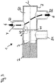
- Figure 1 shows a valve 1 for controlling gas flow, for example an EGR-valve.
- the valve 1 has a housing 7 with at least one gas inlet 50, one first gas outlet 51 and one second gas outlet 52.
- the valve 1 comprises a valve device which controls gas flow from the gas inlet 50 to the first gas outlet 51 and/or the second gas outlet 52.
- the gas flow is indicated by arrows 8.
- a valve body 4 is located in a default position inside a cavity 5.
- the valve body 4 comprises a first valve body element 40 and a second valve body element 41, which are fixedly connected to each other. In the default position, the gas inlet 50 is blocked by the first valve body element 40. Hence, gas is prevented from entering the cavity 5.
- the second valve body element 41 is located between a first gas outlet 51 and a second gas outlet 52.
- the first valve body element 40 has a form to match the inner wall of the cavity 5. In this embodiment it is designed as a section of a cylindrical surface and the second valve body element 41 is formed disc-shaped to be able to block a cross section of the cavity 5.
- the first valve body element 40 and the second valve body element 41 are orientated perpendicular to each other, i.e. the cylindrical surface of the first valve body element 40 is coaxial with a longitudinal axis L of the cavity and the second valve body element 41 is extending perpendicular to longitudinal axis L.
- the valve body 4 is fixedly connected with an axially movable shaft 3, which enables changes of the valve body position inside the cavity 5.
- This shaft 3 is driven by an actuator 2 along the longitudinal axis L.
- the gas inlet 50 is arranged on a first side of the cavity 5 and along an axis Y.
- the first gas outlet 51 as well as the second gas outlet 52 are adjacently arranged on a second side of the cavity 5.
- their orientation is parallel to the axis Y. In other embodiments, their orientation may be at a different angle.
- first gas outlet 51 and the second gas outlet 52 are arranged on the same angle on the cavity 5 surface. In other embodiments, they might be arranged on different angles. In the embodiment shown in figure 1 , the flow path from the gas inlet 50 to the first and second gas outlet 51, 52 is blocked.
- Figure 2 shows a perspective view of the embodiment shown in figure 1 .
- the matching form of the first valve body element 40 and the cavity 5 is clearly visible as well as the disc-shape of the second valve body element 41.
- Figure 3 shows a valve body position, wherein the gas inlet 50 is unblocked as well as the second gas outlet 52, while the first gas outlet 51 is blocked by the second valve body element 41.
- the valve body 4 is brought into this position by the shaft 3, which is driven by the actuator 2.
- gas is able to flow into the cavity 5.
- the amount of inflowing gas can be varied via movement of the valve body 4. If it is moved towards the second gas outlet 52, the first valve body element 40 covers more and more of the gas inlet 50, which causes a lower gas flow volume into the cavity 5 and out of the second gas outlet 52.
- Figure 4 shows another possible position of the valve body 4: the gas inlet 50 and the first gas outlet 51 are unblocked, while the second gas outlet 52 is blocked by the second valve body element 41.
- the valve body 4 may also be moved far right to open gas inlet 50 and both first gas outlet 51 and second gas outlet 52 at the same time.
- valve body 4 can be moved far left or right, so that the gas inlet 50, the first gas outlet 51 and the second gas outlet 52 are opened. This option makes it possible to further adjust the flow rates.
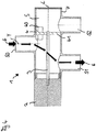
- Figure 5 shows possible valve body positions inside the cavity 5 of the valve 1.
- the axial extension d 0 of the first valve body element 40 is of the same dimensions or greater than the axial extension d i of the gas inlet 50 to ensure tight blocking of the gas inlet 50 in the default position.
- the distance D between the first gas outlet 51 and the second gas outlet 52 should be of sufficient size compared to d 0 to ensure undisturbed operation of the valve.
- valve body 4 Two positions of the valve body 4 are shown in Figure 5 , outlined only schematically in dashed lines.
- the valve body 4 When the valve body 4 is moved to the left (indicated by “A"), the gas inlet 50 and the second gas outlet 52 are completely unblocked. The first gas outlet 51 is partially unblocked. If the valve body 4 is moved far to the right inside the cavity 5 (as indicated by “B"), the gas inlet 40 is completely unblocked as well as the first gas outlet 51 and the second gas outlet 52.
Abstract
Description
- The present invention relates to a valve for controlling gas flow, for example a valve of an exhaust gas recirculation (EGR) system, comprising at least one gas inlet at least one first gas outlet, one second gas outlet and a valve device adapted for blocking or unblocking the first gas outlet and/or the second gas outlet and/or the gas inlet. Furthermore, it relates to a system for the regulation of exhaust gas in a vehicle.
- EGR is a commonly used feature for minimising emissions of nitrogen oxides. For this purpose, exhaust gas is being passed towards a combustion chamber of an engine instead of being emitted. Special valves are being used for separation of the gas flow.
- The amount of exhaust gas flowing back to the combustion chamber needs to be regulated, which is one main function of EGR-valves. Hence, the amount of recirculated gas can be adjusted with high precision to the current load point and operating mode of the engine.
- Bypass valves are used as well in these systems for creating different flow paths. For example, an exhaust gas cooler may be interposed for provision of cooler gas, if this is required for the combustion process. Also, the exhaust gas cooler may be bypassed, if higher exhaust gas temperatures are required.
- It is an object of the present invention to provide a simple and robust valve. Furthermore, it is an object of the present invention to provide an economic system for the recirculation of exhaust gas in a vehicle.
- This object is achieved by means of the valve according to claim 1 and the system according to claim 12. Advantageous embodiments and developments are objects of the dependent claims.
- According to a first aspect of the invention, a valve for controlling gas flow is provided, the valve comprising at least one gas inlet, at least one first gas outlet and one second gas outlet. Furthermore, a valve device adapted for blocking or unblocking the first gas outlet and/or the second gas outlet and/or the gas inlet is provided.
- The valve device according to the first aspect of the invention comprises an axially movable shaft, which is movable along a longitudinal axis L by an actuator. The actuator may be, amongst other possibilities, electrically powered. Typical EGR valve actuators include solenoids, torque motors, stepper motors, and DC motors.
- According to the first aspect of the invention, a valve body is provided, comprising a first valve body element and a second valve body element. The first valve body element and the second valve body element are fixedly connected to each other. The term "fixedly connected" comprises welding, adhesive bonding, screwing as well as forming it in one piece, amongst other examples. The valve body is arranged on the axially movable shaft and hence is axially displaceable.
- Purpose of the first valve body element is blocking or unblocking the gas inlet, while the second valve body element is designed for blocking or unblocking the first gas outlet or the second gas outlet.
- The axially movable shaft is mounted in a way that it moves inside the cavity along the longitudinal axis L. As a consequence, the cavity is arranged along the longitudinal axis L. Axial displacement of the shaft leads to axial displacement of the first valve body element and of the second valve body element. Hence, an axial position of the shaft corresponds to a position of the first valve body element (blocking or unblocking the gas inlet) and of the second valve body element (blocking or unblocking the first and/or the second gas outlet) .
- Therefore, blocking and unblocking of the gas inlet and the gas outlets may be realised only by a linear movement of the shaft along the longitudinal axis L.
- According to an embodiment of the invention, the gas volume flow is adjustable by means of the valve body. This way the valve has not only one, but at least two functional aspects: it combines a bypass valve and a dosing unit, which saves space in the motor compartment and is more economic than using two different items.
- According to an embodiment of the invention, the valve body is blocking the gas inlet in a default position. Default position is hereby defined as a de-energised state of the actuator. In case of a technical malfunction, the valve stays in this position, which shuts down the EGR function and prevents damage to the motor unit.
- According to an embodiment, the valve body is movable to block the first gas outlet or the second gas outlet while unblocking the gas inlet. If both gas outlets are arranged consecutive to each other in the axial direction, this can be achieved by the first valve body element having an axial extension d0 small enough compared to an axial distance D between the first outlet and the second outlet. This way it is possible to choose a position of the second valve body element to either block the first or the second outlet, when the inlet is unblocked.
- This embodiment has the advantage, that the gas flow can be controlled and bypassed in the direction needed.
- According to an embodiment, the valve body is movable to unblock gas inlet and both first gas outlet and second gas outlet at the same time. This can be achieved by the shaft being moveable thus far in an axial direction that the valve body is arranged on one side of the gas inlet, the first gas outlet and the second gas outlet, and not in between.
- According to an embodiment, the valve body is movable to unblock the first gas outlet by blocking the second gas outlet and vice versa. The advantage of this aspect is, that by moving only one valve body, two functions are fulfilled, which saves space in the motor compartment and is more economic due to lesser motor unit weight, lesser parts necessary to be built-in and lesser technically complex solution that may be maintenance intensive.
- According to an embodiment, the first gas outlet and the second gas outlet are placed adjacent in a direction parallel to the longitudinal axis L. According to this embodiment, the first and second gas outlet are consecutive in the direction parallel to the longitudinal axis L and can be blocked or unblocked by axial movement of the shaft.
- According to another embodiment, the valve comprises a cavity, the gas inlet being arranged on a first side of the cavity and the first gas outlet and the second gas outlet being arranged on a second side opposite the first side. Opposite is hereby defined as any position of the first and the second outlet that does not overlap the angle of the gas inlet position on the cavity. The valve body is arranged inside the cavity and is leading the gas stream in a desired direction. According to an embodiment, the cavity has a cylindrical form. This matches common construction shapes, which makes it easier to manufacture in an economic way.
- According to an embodiment, the shape of the first valve body element is matching the cylindrical shape of the cavity and the second valve body element is disc-shaped. This way, the valve body provides an element for blocking or unblocking the gas inlet and an element for blocking or unblocking the first gas outlet and/or the second gas outlet simultaneously.
- According to a second aspect of the invention, a system for the recirculation of exhaust gas in a vehicle is provided. The system comprises at least one gas inlet, at least one first gas outlet and one second gas outlet and a valve. The valve is adapted in a way that makes it suitable for both blocking and unblocking the gas flow from the gas inlet towards the first gas outlet and/or the second gas outlet. This system has the advantages described above in connection with the valve.
- According to an embodiment, the first gas outlet is part of an exhaust gas system, while the second gas outlet leads exhaust gas towards the engine. This embodiment has the advantage, that
- Further advantages, advantageous embodiments and developments of the invention will become apparent from the exemplary embodiments which are described below in association with the schematic figures.
- Figure 1
- shows a longitudinal section of a valve according to a first embodiment of the invention in a closed position;
- Figure 2
- shows the valve according to
figure 1 in a closed position and in a different perspective view; - Figure 3
- shows the valve according to
figure 1 in a first open position; - Figure 4
- shows the valve according to
figure 1 in a second open position. -
Figure 1 shows a valve 1 for controlling gas flow, for example an EGR-valve. The valve 1 has ahousing 7 with at least onegas inlet 50, onefirst gas outlet 51 and onesecond gas outlet 52. - The valve 1 comprises a valve device which controls gas flow from the
gas inlet 50 to thefirst gas outlet 51 and/or thesecond gas outlet 52. The gas flow is indicated by arrows 8. - A
valve body 4 is located in a default position inside acavity 5. Thevalve body 4 comprises a firstvalve body element 40 and a secondvalve body element 41, which are fixedly connected to each other. In the default position, thegas inlet 50 is blocked by the firstvalve body element 40. Hence, gas is prevented from entering thecavity 5. Infigure 1 , the secondvalve body element 41 is located between afirst gas outlet 51 and asecond gas outlet 52. - The first
valve body element 40 has a form to match the inner wall of thecavity 5. In this embodiment it is designed as a section of a cylindrical surface and the secondvalve body element 41 is formed disc-shaped to be able to block a cross section of thecavity 5. - The first
valve body element 40 and the secondvalve body element 41 are orientated perpendicular to each other, i.e. the cylindrical surface of the firstvalve body element 40 is coaxial with a longitudinal axis L of the cavity and the secondvalve body element 41 is extending perpendicular to longitudinal axis L. - The
valve body 4 is fixedly connected with an axiallymovable shaft 3, which enables changes of the valve body position inside thecavity 5. Thisshaft 3 is driven by anactuator 2 along the longitudinal axis L. - The
gas inlet 50 is arranged on a first side of thecavity 5 and along an axis Y. Thefirst gas outlet 51 as well as thesecond gas outlet 52 are adjacently arranged on a second side of thecavity 5. In this embodiment, their orientation is parallel to the axis Y. In other embodiments, their orientation may be at a different angle. - In this embodiment, the
first gas outlet 51 and thesecond gas outlet 52 are arranged on the same angle on thecavity 5 surface. In other embodiments, they might be arranged on different angles. In the embodiment shown infigure 1 , the flow path from thegas inlet 50 to the first andsecond gas outlet -
Figure 2 shows a perspective view of the embodiment shown infigure 1 . The matching form of the firstvalve body element 40 and thecavity 5 is clearly visible as well as the disc-shape of the secondvalve body element 41. -
Figure 3 shows a valve body position, wherein thegas inlet 50 is unblocked as well as thesecond gas outlet 52, while thefirst gas outlet 51 is blocked by the secondvalve body element 41. Thevalve body 4 is brought into this position by theshaft 3, which is driven by theactuator 2. - In this position of the valve 1, gas is able to flow into the
cavity 5. The amount of inflowing gas can be varied via movement of thevalve body 4. If it is moved towards thesecond gas outlet 52, the firstvalve body element 40 covers more and more of thegas inlet 50, which causes a lower gas flow volume into thecavity 5 and out of thesecond gas outlet 52. - In this embodiment, it is also possible to move the
shaft 3 far left, which leads to unblocking thegas inlet 50 and bothfirst gas outlet 51 andsecond gas outlet 52. In this case, gas is enabled to flow both ways at once. -
Figure 4 shows another possible position of the valve body 4: thegas inlet 50 and thefirst gas outlet 51 are unblocked, while thesecond gas outlet 52 is blocked by the secondvalve body element 41. Thevalve body 4 may also be moved far right to opengas inlet 50 and bothfirst gas outlet 51 andsecond gas outlet 52 at the same time. - In a further example, the
valve body 4 can be moved far left or right, so that thegas inlet 50, thefirst gas outlet 51 and thesecond gas outlet 52 are opened. This option makes it possible to further adjust the flow rates. -
Figure 5 shows possible valve body positions inside thecavity 5 of the valve 1. The axial extension d0 of the firstvalve body element 40 is of the same dimensions or greater than the axial extension di of thegas inlet 50 to ensure tight blocking of thegas inlet 50 in the default position. The distance D between thefirst gas outlet 51 and thesecond gas outlet 52 should be of sufficient size compared to d0 to ensure undisturbed operation of the valve. - Two positions of the
valve body 4 are shown inFigure 5 , outlined only schematically in dashed lines. When thevalve body 4 is moved to the left (indicated by "A"), thegas inlet 50 and thesecond gas outlet 52 are completely unblocked. Thefirst gas outlet 51 is partially unblocked. If thevalve body 4 is moved far to the right inside the cavity 5 (as indicated by "B"), thegas inlet 40 is completely unblocked as well as thefirst gas outlet 51 and thesecond gas outlet 52.
Claims (12)
- Valve (1) for controlling gas flow, comprising- a housing (7) with at least one gas inlet (50); at least one first gas outlet (51) and one second gas outlet (52);- a valve device adapted for blocking or unblocking the first gas outlet (51) and/or the second gas outlet (52) and/or the gas inlet (50);the valve device comprising- an axially movable shaft (3) driven by an actuator (2) ;- a valve body (4) comprising a first valve body element (40) and a second valve body element (41) and being arranged on the axially movable shaft (3);- the first valve body element (40) being adapted for blocking or unblocking the gas inlet (50);- the second valve body element (41) being adapted for blocking or unblocking the first gas outlet (51) or the second gas outlet (52);- the first valve body element (40) and the second valve body element (41) being fixedly connected to each other; wherein the valve body (4) is adapted to block or unblock the gas inlet (50), the first gas outlet (51) and the second gas outlet (52) via linear movement along a longitudinal axis L of the shaft (3).
- Valve (1) according to claim 1,
wherein a volume of a gas flow is adjustable by means of the valve body (4). - Valve (1) according to claim 1 or 2,
wherein the valve body (4) is arranged to block the gas inlet (50) in a default position. - Valve (1) according to any one of claims 1 to 3,
wherein the valve body (4) is movable to block the first gas outlet (51) or the second gas outlet (52) while unblocking the gas inlet (50). - Valve (1) according to any one of claims 1 to 3,
wherein the valve body (4) is movable to unblock gas inlet (50) and both first gas outlet (51) and second gas outlet (52) at the same time. - Valve (1) according to any one of claims 1 to 3,
wherein the valve body (4) is movable to unblock the first gas outlet (51) by blocking the second gas outlet (52) and vice versa. - Valve (1) according to any one of the claims 1 to 6,
wherein the first gas outlet (51) and the second gas outlet (52) are placed adjacent in a direction parallel to the longitudinal axis L. - Valve (1) according to any one of the claims 1 to 7,
wherein the valve (1) comprises a cavity (5), the gas inlet (50) being arranged on a first side of the cavity (5) and the first gas outlet (51) and the second gas outlet (52) being arranged on a second side opposite the first side of the cavity (5). - Valve (1) according to any one of the claims 1 to 8,
wherein the cavity (5) has a cylindrical form. - Valve (1) according to any one of claim 1 to 9,
wherein the shape of the first valve body element (40) is matching the cylindrical shape of the cavity (5) and the second valve body element (41) is disc-shaped. - System for the recirculation of exhaust gas in a vehicle, comprising- at least one gas inlet (50), at least one first gas outlet (51) and one second gas outlet (52);- a valve (1) according to any of claims 1 to 6, the valve (1) being adapted for blocking or unblocking gas flow from the gas inlet (50) to the first gas outlet (51) and/or the second gas outlet (52).
- System according to claim 11,
wherein the first gas outlet (51) is part of an exhaust gas system, while the second gas outlet (52) leads exhaust gas to the engine.
Priority Applications (1)
| Application Number | Priority Date | Filing Date | Title |
|---|---|---|---|
| EP18465584.3A EP3633180B1 (en) | 2018-10-01 | 2018-10-01 | Valve for controlling gas flow and system for exhaust gas recirculation to an internal combustion engine |
Applications Claiming Priority (1)
| Application Number | Priority Date | Filing Date | Title |
|---|---|---|---|
| EP18465584.3A EP3633180B1 (en) | 2018-10-01 | 2018-10-01 | Valve for controlling gas flow and system for exhaust gas recirculation to an internal combustion engine |
Publications (2)
| Publication Number | Publication Date |
|---|---|
| EP3633180A1 true EP3633180A1 (en) | 2020-04-08 |
| EP3633180B1 EP3633180B1 (en) | 2021-04-28 |
Family
ID=63965597
Family Applications (1)
| Application Number | Title | Priority Date | Filing Date |
|---|---|---|---|
| EP18465584.3A Active EP3633180B1 (en) | 2018-10-01 | 2018-10-01 | Valve for controlling gas flow and system for exhaust gas recirculation to an internal combustion engine |
Country Status (1)
| Country | Link |
|---|---|
| EP (1) | EP3633180B1 (en) |
Citations (3)
| Publication number | Priority date | Publication date | Assignee | Title |
|---|---|---|---|---|
| DE102008005400A1 (en) * | 2007-01-19 | 2008-07-24 | Behr Thermot-Tronik Gmbh | Heat exchanger valve device for exhaust gas heat exchanger, has valve housing with inlet for fluid flow and outlet through which larger or smaller liquid flow is guided to heat exchanger |
| FR2917802A1 (en) * | 2007-06-21 | 2008-12-26 | Valeo Sys Controle Moteur Sas | EXHAUST GAS RECIRCULATION VALVE |
| US20100181517A1 (en) * | 2009-01-16 | 2010-07-22 | Fernando Roberto Paz Briz | Helical Fluid Flow Conduit |
-
2018
- 2018-10-01 EP EP18465584.3A patent/EP3633180B1/en active Active
Patent Citations (3)
| Publication number | Priority date | Publication date | Assignee | Title |
|---|---|---|---|---|
| DE102008005400A1 (en) * | 2007-01-19 | 2008-07-24 | Behr Thermot-Tronik Gmbh | Heat exchanger valve device for exhaust gas heat exchanger, has valve housing with inlet for fluid flow and outlet through which larger or smaller liquid flow is guided to heat exchanger |
| FR2917802A1 (en) * | 2007-06-21 | 2008-12-26 | Valeo Sys Controle Moteur Sas | EXHAUST GAS RECIRCULATION VALVE |
| US20100181517A1 (en) * | 2009-01-16 | 2010-07-22 | Fernando Roberto Paz Briz | Helical Fluid Flow Conduit |
Also Published As
| Publication number | Publication date |
|---|---|
| EP3633180B1 (en) | 2021-04-28 |
Similar Documents
| Publication | Publication Date | Title |
|---|---|---|
| US10151277B2 (en) | High and low pressure EGR with a common valve housing | |
| US7721973B2 (en) | Valve | |
| US8690072B2 (en) | Radiator bypass valve | |
| CN102822577B (en) | Multifunction valve | |
| US20200318531A1 (en) | Turbine for an exhaust turbocharger having a two-volute turbine housing and a linear valve for volute connection and wastegate control | |
| WO2006126963A1 (en) | Apparatus for recirculation of exhaust gases in a combustion engine | |
| US20120230814A1 (en) | Diffuser for a turbocharger having an adjustable turbine geometry and turbocharger for an internal combustion engine | |
| EP3633180B1 (en) | Valve for controlling gas flow and system for exhaust gas recirculation to an internal combustion engine | |
| EP1996811B1 (en) | Two component low pressure egr module | |
| DE102010020709A1 (en) | Control device for a turbo-charged internal combustion engine | |
| EP3440333B1 (en) | Exhaust gas valve device | |
| EP3325814B1 (en) | Valve assembly for a pump with improved regulation of the passage of cooling liquid | |
| US20160017846A1 (en) | Fluid switching device for a valve having at least three ports | |
| JP2009228758A (en) | Flow regulating device | |
| US20190048749A1 (en) | Waste heat recovery system | |
| US20200392882A1 (en) | Valve, exhaust branch for an internal combustion engine and vehicle having an internal combustion engine | |
| US9574523B2 (en) | Fluid flow valve, particularly for a motor vehicle, and a temperature regulation device including one such valve | |
| JP6384286B2 (en) | Valve unit | |
| WO2017178861A1 (en) | A flow control device between a first line and a second line | |
| JP6258300B2 (en) | Two-channel metering device and its use | |
| US20180038291A1 (en) | Throttle valve assembly | |
| US10400665B2 (en) | Assembly for an air circuit of a heat engine | |
| EP3633179A1 (en) | Valve for controlling gas flow and system for exhaust gas recirculation to an internal combustion engine | |
| EP3321487B1 (en) | Rotary electromechanical actuator for powertrain applications, in particular for a turbocharger adjusting system | |
| EP3129686A1 (en) | Flow control valve and method for operating a flow control valve |
Legal Events
| Date | Code | Title | Description |
|---|---|---|---|
| PUAI | Public reference made under article 153(3) epc to a published international application that has entered the european phase |
Free format text: ORIGINAL CODE: 0009012 |
|
| STAA | Information on the status of an ep patent application or granted ep patent |
Free format text: STATUS: THE APPLICATION HAS BEEN PUBLISHED |
|
| AK | Designated contracting states |
Kind code of ref document: A1 Designated state(s): AL AT BE BG CH CY CZ DE DK EE ES FI FR GB GR HR HU IE IS IT LI LT LU LV MC MK MT NL NO PL PT RO RS SE SI SK SM TR |
|
| AX | Request for extension of the european patent |
Extension state: BA ME |
|
| RAP1 | Party data changed (applicant data changed or rights of an application transferred) |
Owner name: VITESCO TECHNOLOGIES GMBH |
|
| STAA | Information on the status of an ep patent application or granted ep patent |
Free format text: STATUS: REQUEST FOR EXAMINATION WAS MADE |
|
| 17P | Request for examination filed |
Effective date: 20201008 |
|
| RBV | Designated contracting states (corrected) |
Designated state(s): AL AT BE BG CH CY CZ DE DK EE ES FI FR GB GR HR HU IE IS IT LI LT LU LV MC MK MT NL NO PL PT RO RS SE SI SK SM TR |
|
| GRAP | Despatch of communication of intention to grant a patent |
Free format text: ORIGINAL CODE: EPIDOSNIGR1 |
|
| STAA | Information on the status of an ep patent application or granted ep patent |
Free format text: STATUS: GRANT OF PATENT IS INTENDED |
|
| RIC1 | Information provided on ipc code assigned before grant |
Ipc: F02M 26/26 20160101ALI20201124BHEP Ipc: F02M 26/68 20160101ALI20201124BHEP Ipc: F02M 26/69 20160101ALI20201124BHEP Ipc: F02M 26/70 20160101ALI20201124BHEP Ipc: F16K 3/00 20060101ALI20201124BHEP Ipc: F16K 11/00 20060101ALI20201124BHEP Ipc: F02M 26/71 20160101AFI20201124BHEP |
|
| INTG | Intention to grant announced |
Effective date: 20201215 |
|
| GRAS | Grant fee paid |
Free format text: ORIGINAL CODE: EPIDOSNIGR3 |
|
| GRAA | (expected) grant |
Free format text: ORIGINAL CODE: 0009210 |
|
| STAA | Information on the status of an ep patent application or granted ep patent |
Free format text: STATUS: THE PATENT HAS BEEN GRANTED |
|
| AK | Designated contracting states |
Kind code of ref document: B1 Designated state(s): AL AT BE BG CH CY CZ DE DK EE ES FI FR GB GR HR HU IE IS IT LI LT LU LV MC MK MT NL NO PL PT RO RS SE SI SK SM TR |
|
| REG | Reference to a national code |
Ref country code: GB Ref legal event code: FG4D |
|
| REG | Reference to a national code |
Ref country code: CH Ref legal event code: EP |
|
| REG | Reference to a national code |
Ref country code: AT Ref legal event code: REF Ref document number: 1387334 Country of ref document: AT Kind code of ref document: T Effective date: 20210515 |
|
| REG | Reference to a national code |
Ref country code: DE Ref legal event code: R096 Ref document number: 602018016163 Country of ref document: DE |
|
| REG | Reference to a national code |
Ref country code: IE Ref legal event code: FG4D |
|
| REG | Reference to a national code |
Ref country code: LT Ref legal event code: MG9D |
|
| REG | Reference to a national code |
Ref country code: AT Ref legal event code: MK05 Ref document number: 1387334 Country of ref document: AT Kind code of ref document: T Effective date: 20210428 |
|
| PG25 | Lapsed in a contracting state [announced via postgrant information from national office to epo] |
Ref country code: BG Free format text: LAPSE BECAUSE OF FAILURE TO SUBMIT A TRANSLATION OF THE DESCRIPTION OR TO PAY THE FEE WITHIN THE PRESCRIBED TIME-LIMIT Effective date: 20210728 Ref country code: AT Free format text: LAPSE BECAUSE OF FAILURE TO SUBMIT A TRANSLATION OF THE DESCRIPTION OR TO PAY THE FEE WITHIN THE PRESCRIBED TIME-LIMIT Effective date: 20210428 Ref country code: NL Free format text: LAPSE BECAUSE OF FAILURE TO SUBMIT A TRANSLATION OF THE DESCRIPTION OR TO PAY THE FEE WITHIN THE PRESCRIBED TIME-LIMIT Effective date: 20210428 Ref country code: LT Free format text: LAPSE BECAUSE OF FAILURE TO SUBMIT A TRANSLATION OF THE DESCRIPTION OR TO PAY THE FEE WITHIN THE PRESCRIBED TIME-LIMIT Effective date: 20210428 Ref country code: HR Free format text: LAPSE BECAUSE OF FAILURE TO SUBMIT A TRANSLATION OF THE DESCRIPTION OR TO PAY THE FEE WITHIN THE PRESCRIBED TIME-LIMIT Effective date: 20210428 Ref country code: FI Free format text: LAPSE BECAUSE OF FAILURE TO SUBMIT A TRANSLATION OF THE DESCRIPTION OR TO PAY THE FEE WITHIN THE PRESCRIBED TIME-LIMIT Effective date: 20210428 |
|
| PG25 | Lapsed in a contracting state [announced via postgrant information from national office to epo] |
Ref country code: IS Free format text: LAPSE BECAUSE OF FAILURE TO SUBMIT A TRANSLATION OF THE DESCRIPTION OR TO PAY THE FEE WITHIN THE PRESCRIBED TIME-LIMIT Effective date: 20210828 Ref country code: GR Free format text: LAPSE BECAUSE OF FAILURE TO SUBMIT A TRANSLATION OF THE DESCRIPTION OR TO PAY THE FEE WITHIN THE PRESCRIBED TIME-LIMIT Effective date: 20210729 Ref country code: LV Free format text: LAPSE BECAUSE OF FAILURE TO SUBMIT A TRANSLATION OF THE DESCRIPTION OR TO PAY THE FEE WITHIN THE PRESCRIBED TIME-LIMIT Effective date: 20210428 Ref country code: PL Free format text: LAPSE BECAUSE OF FAILURE TO SUBMIT A TRANSLATION OF THE DESCRIPTION OR TO PAY THE FEE WITHIN THE PRESCRIBED TIME-LIMIT Effective date: 20210428 Ref country code: PT Free format text: LAPSE BECAUSE OF FAILURE TO SUBMIT A TRANSLATION OF THE DESCRIPTION OR TO PAY THE FEE WITHIN THE PRESCRIBED TIME-LIMIT Effective date: 20210830 Ref country code: NO Free format text: LAPSE BECAUSE OF FAILURE TO SUBMIT A TRANSLATION OF THE DESCRIPTION OR TO PAY THE FEE WITHIN THE PRESCRIBED TIME-LIMIT Effective date: 20210728 Ref country code: SE Free format text: LAPSE BECAUSE OF FAILURE TO SUBMIT A TRANSLATION OF THE DESCRIPTION OR TO PAY THE FEE WITHIN THE PRESCRIBED TIME-LIMIT Effective date: 20210428 Ref country code: RS Free format text: LAPSE BECAUSE OF FAILURE TO SUBMIT A TRANSLATION OF THE DESCRIPTION OR TO PAY THE FEE WITHIN THE PRESCRIBED TIME-LIMIT Effective date: 20210428 |
|
| RAP4 | Party data changed (patent owner data changed or rights of a patent transferred) |
Owner name: VITESCO TECHNOLOGIES GMBH |
|
| REG | Reference to a national code |
Ref country code: NL Ref legal event code: MP Effective date: 20210428 |
|
| REG | Reference to a national code |
Ref country code: DE Ref legal event code: R081 Ref document number: 602018016163 Country of ref document: DE Owner name: VITESCO TECHNOLOGIES GMBH, DE Free format text: FORMER OWNER: VITESCO TECHNOLOGIES GMBH, 30165 HANNOVER, DE |
|
| PG25 | Lapsed in a contracting state [announced via postgrant information from national office to epo] |
Ref country code: EE Free format text: LAPSE BECAUSE OF FAILURE TO SUBMIT A TRANSLATION OF THE DESCRIPTION OR TO PAY THE FEE WITHIN THE PRESCRIBED TIME-LIMIT Effective date: 20210428 Ref country code: ES Free format text: LAPSE BECAUSE OF FAILURE TO SUBMIT A TRANSLATION OF THE DESCRIPTION OR TO PAY THE FEE WITHIN THE PRESCRIBED TIME-LIMIT Effective date: 20210428 Ref country code: SK Free format text: LAPSE BECAUSE OF FAILURE TO SUBMIT A TRANSLATION OF THE DESCRIPTION OR TO PAY THE FEE WITHIN THE PRESCRIBED TIME-LIMIT Effective date: 20210428 Ref country code: SM Free format text: LAPSE BECAUSE OF FAILURE TO SUBMIT A TRANSLATION OF THE DESCRIPTION OR TO PAY THE FEE WITHIN THE PRESCRIBED TIME-LIMIT Effective date: 20210428 Ref country code: CZ Free format text: LAPSE BECAUSE OF FAILURE TO SUBMIT A TRANSLATION OF THE DESCRIPTION OR TO PAY THE FEE WITHIN THE PRESCRIBED TIME-LIMIT Effective date: 20210428 Ref country code: DK Free format text: LAPSE BECAUSE OF FAILURE TO SUBMIT A TRANSLATION OF THE DESCRIPTION OR TO PAY THE FEE WITHIN THE PRESCRIBED TIME-LIMIT Effective date: 20210428 Ref country code: RO Free format text: LAPSE BECAUSE OF FAILURE TO SUBMIT A TRANSLATION OF THE DESCRIPTION OR TO PAY THE FEE WITHIN THE PRESCRIBED TIME-LIMIT Effective date: 20210428 |
|
| REG | Reference to a national code |
Ref country code: DE Ref legal event code: R097 Ref document number: 602018016163 Country of ref document: DE |
|
| PLBE | No opposition filed within time limit |
Free format text: ORIGINAL CODE: 0009261 |
|
| STAA | Information on the status of an ep patent application or granted ep patent |
Free format text: STATUS: NO OPPOSITION FILED WITHIN TIME LIMIT |
|
| 26N | No opposition filed |
Effective date: 20220131 |
|
| REG | Reference to a national code |
Ref country code: CH Ref legal event code: PL |
|
| PG25 | Lapsed in a contracting state [announced via postgrant information from national office to epo] |
Ref country code: IS Free format text: LAPSE BECAUSE OF FAILURE TO SUBMIT A TRANSLATION OF THE DESCRIPTION OR TO PAY THE FEE WITHIN THE PRESCRIBED TIME-LIMIT Effective date: 20210828 Ref country code: AL Free format text: LAPSE BECAUSE OF FAILURE TO SUBMIT A TRANSLATION OF THE DESCRIPTION OR TO PAY THE FEE WITHIN THE PRESCRIBED TIME-LIMIT Effective date: 20210428 |
|
| REG | Reference to a national code |
Ref country code: BE Ref legal event code: MM Effective date: 20211031 |
|
| PG25 | Lapsed in a contracting state [announced via postgrant information from national office to epo] |
Ref country code: MC Free format text: LAPSE BECAUSE OF FAILURE TO SUBMIT A TRANSLATION OF THE DESCRIPTION OR TO PAY THE FEE WITHIN THE PRESCRIBED TIME-LIMIT Effective date: 20210428 |
|
| PG25 | Lapsed in a contracting state [announced via postgrant information from national office to epo] |
Ref country code: LU Free format text: LAPSE BECAUSE OF NON-PAYMENT OF DUE FEES Effective date: 20211001 Ref country code: IT Free format text: LAPSE BECAUSE OF FAILURE TO SUBMIT A TRANSLATION OF THE DESCRIPTION OR TO PAY THE FEE WITHIN THE PRESCRIBED TIME-LIMIT Effective date: 20210428 Ref country code: BE Free format text: LAPSE BECAUSE OF NON-PAYMENT OF DUE FEES Effective date: 20211031 |
|
| PG25 | Lapsed in a contracting state [announced via postgrant information from national office to epo] |
Ref country code: LI Free format text: LAPSE BECAUSE OF NON-PAYMENT OF DUE FEES Effective date: 20211031 Ref country code: CH Free format text: LAPSE BECAUSE OF NON-PAYMENT OF DUE FEES Effective date: 20211031 |
|
| PG25 | Lapsed in a contracting state [announced via postgrant information from national office to epo] |
Ref country code: IE Free format text: LAPSE BECAUSE OF NON-PAYMENT OF DUE FEES Effective date: 20211001 |
|
| GBPC | Gb: european patent ceased through non-payment of renewal fee |
Effective date: 20221001 |
|
| PG25 | Lapsed in a contracting state [announced via postgrant information from national office to epo] |
Ref country code: CY Free format text: LAPSE BECAUSE OF FAILURE TO SUBMIT A TRANSLATION OF THE DESCRIPTION OR TO PAY THE FEE WITHIN THE PRESCRIBED TIME-LIMIT Effective date: 20210428 |
|
| P01 | Opt-out of the competence of the unified patent court (upc) registered |
Effective date: 20230530 |
|
| PG25 | Lapsed in a contracting state [announced via postgrant information from national office to epo] |
Ref country code: HU Free format text: LAPSE BECAUSE OF FAILURE TO SUBMIT A TRANSLATION OF THE DESCRIPTION OR TO PAY THE FEE WITHIN THE PRESCRIBED TIME-LIMIT; INVALID AB INITIO Effective date: 20181001 |
|
| PG25 | Lapsed in a contracting state [announced via postgrant information from national office to epo] |
Ref country code: GB Free format text: LAPSE BECAUSE OF NON-PAYMENT OF DUE FEES Effective date: 20221001 |
|
| PGFP | Annual fee paid to national office [announced via postgrant information from national office to epo] |
Ref country code: FR Payment date: 20231026 Year of fee payment: 6 Ref country code: DE Payment date: 20231031 Year of fee payment: 6 |