EP3633155A1 - Additively manufactured thermally insulating structure - Google Patents
Additively manufactured thermally insulating structure Download PDFInfo
- Publication number
- EP3633155A1 EP3633155A1 EP19201790.3A EP19201790A EP3633155A1 EP 3633155 A1 EP3633155 A1 EP 3633155A1 EP 19201790 A EP19201790 A EP 19201790A EP 3633155 A1 EP3633155 A1 EP 3633155A1
- Authority
- EP
- European Patent Office
- Prior art keywords
- additively manufactured
- thermally insulating
- gas turbine
- fire
- turbine engine
- Prior art date
- Legal status (The legal status is an assumption and is not a legal conclusion. Google has not performed a legal analysis and makes no representation as to the accuracy of the status listed.)
- Granted
Links
- 230000009970 fire resistant effect Effects 0.000 claims abstract description 29
- 238000004519 manufacturing process Methods 0.000 claims abstract description 29
- 230000003068 static effect Effects 0.000 claims abstract description 23
- 238000000034 method Methods 0.000 claims abstract description 17
- 229910045601 alloy Inorganic materials 0.000 description 8
- 239000000956 alloy Substances 0.000 description 8
- 239000000654 additive Substances 0.000 description 5
- 230000000996 additive effect Effects 0.000 description 5
- PXHVJJICTQNCMI-UHFFFAOYSA-N Nickel Chemical compound [Ni] PXHVJJICTQNCMI-UHFFFAOYSA-N 0.000 description 4
- 238000010894 electron beam technology Methods 0.000 description 4
- 239000000463 material Substances 0.000 description 4
- 238000001816 cooling Methods 0.000 description 3
- 239000000446 fuel Substances 0.000 description 3
- 239000000843 powder Substances 0.000 description 3
- 229910000684 Cobalt-chrome Inorganic materials 0.000 description 2
- RTAQQCXQSZGOHL-UHFFFAOYSA-N Titanium Chemical compound [Ti] RTAQQCXQSZGOHL-UHFFFAOYSA-N 0.000 description 2
- 229910001315 Tool steel Inorganic materials 0.000 description 2
- 229910052782 aluminium Inorganic materials 0.000 description 2
- XAGFODPZIPBFFR-UHFFFAOYSA-N aluminium Chemical compound [Al] XAGFODPZIPBFFR-UHFFFAOYSA-N 0.000 description 2
- 239000010952 cobalt-chrome Substances 0.000 description 2
- 230000004927 fusion Effects 0.000 description 2
- 239000011159 matrix material Substances 0.000 description 2
- 229910052759 nickel Inorganic materials 0.000 description 2
- 238000000110 selective laser sintering Methods 0.000 description 2
- 229910001220 stainless steel Inorganic materials 0.000 description 2
- 239000010935 stainless steel Substances 0.000 description 2
- 229910052719 titanium Inorganic materials 0.000 description 2
- 239000010936 titanium Substances 0.000 description 2
- 239000004593 Epoxy Substances 0.000 description 1
- JOYRKODLDBILNP-UHFFFAOYSA-N Ethyl urethane Chemical compound CCOC(N)=O JOYRKODLDBILNP-UHFFFAOYSA-N 0.000 description 1
- 239000004677 Nylon Substances 0.000 description 1
- 238000003848 UV Light-Curing Methods 0.000 description 1
- 239000004676 acrylonitrile butadiene styrene Substances 0.000 description 1
- 239000000919 ceramic Substances 0.000 description 1
- 238000002485 combustion reaction Methods 0.000 description 1
- 239000002131 composite material Substances 0.000 description 1
- 238000010276 construction Methods 0.000 description 1
- 238000000151 deposition Methods 0.000 description 1
- 230000008021 deposition Effects 0.000 description 1
- 239000004744 fabric Substances 0.000 description 1
- 239000003063 flame retardant Substances 0.000 description 1
- 230000010354 integration Effects 0.000 description 1
- 238000002955 isolation Methods 0.000 description 1
- 238000002844 melting Methods 0.000 description 1
- 230000008018 melting Effects 0.000 description 1
- 229910001092 metal group alloy Inorganic materials 0.000 description 1
- 239000007769 metal material Substances 0.000 description 1
- 238000001465 metallisation Methods 0.000 description 1
- 238000012986 modification Methods 0.000 description 1
- 230000004048 modification Effects 0.000 description 1
- 229920001778 nylon Polymers 0.000 description 1
- 239000004626 polylactic acid Substances 0.000 description 1
- 229920001296 polysiloxane Polymers 0.000 description 1
- 239000004814 polyurethane Substances 0.000 description 1
- 229920002635 polyurethane Polymers 0.000 description 1
- 230000000135 prohibitive effect Effects 0.000 description 1
- 230000000717 retained effect Effects 0.000 description 1
- 238000007493 shaping process Methods 0.000 description 1
- 238000005245 sintering Methods 0.000 description 1
- 239000004449 solid propellant Substances 0.000 description 1
- 235000012773 waffles Nutrition 0.000 description 1
- 238000003466 welding Methods 0.000 description 1
Images


Classifications
-
- F—MECHANICAL ENGINEERING; LIGHTING; HEATING; WEAPONS; BLASTING
- F01—MACHINES OR ENGINES IN GENERAL; ENGINE PLANTS IN GENERAL; STEAM ENGINES
- F01D—NON-POSITIVE DISPLACEMENT MACHINES OR ENGINES, e.g. STEAM TURBINES
- F01D25/00—Component parts, details, or accessories, not provided for in, or of interest apart from, other groups
- F01D25/08—Cooling; Heating; Heat-insulation
- F01D25/14—Casings modified therefor
- F01D25/145—Thermally insulated casings
-
- B—PERFORMING OPERATIONS; TRANSPORTING
- B33—ADDITIVE MANUFACTURING TECHNOLOGY
- B33Y—ADDITIVE MANUFACTURING, i.e. MANUFACTURING OF THREE-DIMENSIONAL [3-D] OBJECTS BY ADDITIVE DEPOSITION, ADDITIVE AGGLOMERATION OR ADDITIVE LAYERING, e.g. BY 3-D PRINTING, STEREOLITHOGRAPHY OR SELECTIVE LASER SINTERING
- B33Y10/00—Processes of additive manufacturing
-
- B—PERFORMING OPERATIONS; TRANSPORTING
- B33—ADDITIVE MANUFACTURING TECHNOLOGY
- B33Y—ADDITIVE MANUFACTURING, i.e. MANUFACTURING OF THREE-DIMENSIONAL [3-D] OBJECTS BY ADDITIVE DEPOSITION, ADDITIVE AGGLOMERATION OR ADDITIVE LAYERING, e.g. BY 3-D PRINTING, STEREOLITHOGRAPHY OR SELECTIVE LASER SINTERING
- B33Y80/00—Products made by additive manufacturing
-
- F—MECHANICAL ENGINEERING; LIGHTING; HEATING; WEAPONS; BLASTING
- F02—COMBUSTION ENGINES; HOT-GAS OR COMBUSTION-PRODUCT ENGINE PLANTS
- F02C—GAS-TURBINE PLANTS; AIR INTAKES FOR JET-PROPULSION PLANTS; CONTROLLING FUEL SUPPLY IN AIR-BREATHING JET-PROPULSION PLANTS
- F02C7/00—Features, components parts, details or accessories, not provided for in, or of interest apart form groups F02C1/00 - F02C6/00; Air intakes for jet-propulsion plants
- F02C7/04—Air intakes for gas-turbine plants or jet-propulsion plants
-
- F—MECHANICAL ENGINEERING; LIGHTING; HEATING; WEAPONS; BLASTING
- F02—COMBUSTION ENGINES; HOT-GAS OR COMBUSTION-PRODUCT ENGINE PLANTS
- F02C—GAS-TURBINE PLANTS; AIR INTAKES FOR JET-PROPULSION PLANTS; CONTROLLING FUEL SUPPLY IN AIR-BREATHING JET-PROPULSION PLANTS
- F02C7/00—Features, components parts, details or accessories, not provided for in, or of interest apart form groups F02C1/00 - F02C6/00; Air intakes for jet-propulsion plants
- F02C7/24—Heat or noise insulation
- F02C7/25—Fire protection or prevention
-
- B—PERFORMING OPERATIONS; TRANSPORTING
- B22—CASTING; POWDER METALLURGY
- B22F—WORKING METALLIC POWDER; MANUFACTURE OF ARTICLES FROM METALLIC POWDER; MAKING METALLIC POWDER; APPARATUS OR DEVICES SPECIALLY ADAPTED FOR METALLIC POWDER
- B22F10/00—Additive manufacturing of workpieces or articles from metallic powder
- B22F10/20—Direct sintering or melting
- B22F10/25—Direct deposition of metal particles, e.g. direct metal deposition [DMD] or laser engineered net shaping [LENS]
-
- B—PERFORMING OPERATIONS; TRANSPORTING
- B22—CASTING; POWDER METALLURGY
- B22F—WORKING METALLIC POWDER; MANUFACTURE OF ARTICLES FROM METALLIC POWDER; MAKING METALLIC POWDER; APPARATUS OR DEVICES SPECIALLY ADAPTED FOR METALLIC POWDER
- B22F10/00—Additive manufacturing of workpieces or articles from metallic powder
- B22F10/20—Direct sintering or melting
- B22F10/28—Powder bed fusion, e.g. selective laser melting [SLM] or electron beam melting [EBM]
-
- F—MECHANICAL ENGINEERING; LIGHTING; HEATING; WEAPONS; BLASTING
- F05—INDEXING SCHEMES RELATING TO ENGINES OR PUMPS IN VARIOUS SUBCLASSES OF CLASSES F01-F04
- F05D—INDEXING SCHEME FOR ASPECTS RELATING TO NON-POSITIVE-DISPLACEMENT MACHINES OR ENGINES, GAS-TURBINES OR JET-PROPULSION PLANTS
- F05D2220/00—Application
- F05D2220/30—Application in turbines
- F05D2220/32—Application in turbines in gas turbines
-
- F—MECHANICAL ENGINEERING; LIGHTING; HEATING; WEAPONS; BLASTING
- F05—INDEXING SCHEMES RELATING TO ENGINES OR PUMPS IN VARIOUS SUBCLASSES OF CLASSES F01-F04
- F05D—INDEXING SCHEME FOR ASPECTS RELATING TO NON-POSITIVE-DISPLACEMENT MACHINES OR ENGINES, GAS-TURBINES OR JET-PROPULSION PLANTS
- F05D2230/00—Manufacture
- F05D2230/30—Manufacture with deposition of material
- F05D2230/31—Layer deposition
-
- F—MECHANICAL ENGINEERING; LIGHTING; HEATING; WEAPONS; BLASTING
- F05—INDEXING SCHEMES RELATING TO ENGINES OR PUMPS IN VARIOUS SUBCLASSES OF CLASSES F01-F04
- F05D—INDEXING SCHEME FOR ASPECTS RELATING TO NON-POSITIVE-DISPLACEMENT MACHINES OR ENGINES, GAS-TURBINES OR JET-PROPULSION PLANTS
- F05D2240/00—Components
- F05D2240/10—Stators
- F05D2240/14—Casings or housings protecting or supporting assemblies within
-
- F—MECHANICAL ENGINEERING; LIGHTING; HEATING; WEAPONS; BLASTING
- F05—INDEXING SCHEMES RELATING TO ENGINES OR PUMPS IN VARIOUS SUBCLASSES OF CLASSES F01-F04
- F05D—INDEXING SCHEME FOR ASPECTS RELATING TO NON-POSITIVE-DISPLACEMENT MACHINES OR ENGINES, GAS-TURBINES OR JET-PROPULSION PLANTS
- F05D2250/00—Geometry
- F05D2250/80—Size or power range of the machines
- F05D2250/82—Micromachines
-
- F—MECHANICAL ENGINEERING; LIGHTING; HEATING; WEAPONS; BLASTING
- F05—INDEXING SCHEMES RELATING TO ENGINES OR PUMPS IN VARIOUS SUBCLASSES OF CLASSES F01-F04
- F05D—INDEXING SCHEME FOR ASPECTS RELATING TO NON-POSITIVE-DISPLACEMENT MACHINES OR ENGINES, GAS-TURBINES OR JET-PROPULSION PLANTS
- F05D2300/00—Materials; Properties thereof
- F05D2300/50—Intrinsic material properties or characteristics
- F05D2300/502—Thermal properties
-
- Y—GENERAL TAGGING OF NEW TECHNOLOGICAL DEVELOPMENTS; GENERAL TAGGING OF CROSS-SECTIONAL TECHNOLOGIES SPANNING OVER SEVERAL SECTIONS OF THE IPC; TECHNICAL SUBJECTS COVERED BY FORMER USPC CROSS-REFERENCE ART COLLECTIONS [XRACs] AND DIGESTS
- Y02—TECHNOLOGIES OR APPLICATIONS FOR MITIGATION OR ADAPTATION AGAINST CLIMATE CHANGE
- Y02P—CLIMATE CHANGE MITIGATION TECHNOLOGIES IN THE PRODUCTION OR PROCESSING OF GOODS
- Y02P10/00—Technologies related to metal processing
- Y02P10/25—Process efficiency
-
- Y—GENERAL TAGGING OF NEW TECHNOLOGICAL DEVELOPMENTS; GENERAL TAGGING OF CROSS-SECTIONAL TECHNOLOGIES SPANNING OVER SEVERAL SECTIONS OF THE IPC; TECHNICAL SUBJECTS COVERED BY FORMER USPC CROSS-REFERENCE ART COLLECTIONS [XRACs] AND DIGESTS
- Y02—TECHNOLOGIES OR APPLICATIONS FOR MITIGATION OR ADAPTATION AGAINST CLIMATE CHANGE
- Y02T—CLIMATE CHANGE MITIGATION TECHNOLOGIES RELATED TO TRANSPORTATION
- Y02T50/00—Aeronautics or air transport
- Y02T50/60—Efficient propulsion technologies, e.g. for aircraft
Definitions
- the present disclosure relates to additive manufacturing and, more particularly, to an additively manufactured thermally insulating structure for a miniature gas turbine or turbojet engines.
- Miniature gas turbine or turbojet engines that are typically 1000 pound-force (lbf) (4.45 kN) thrust and smaller, are often utilized in attritable or expendable applications such as reconnaissance drones, cruise missiles, decoys, and other applications, including air-launched and ground-launched weapon systems.
- the use of such single use gas turbine engines greatly extends the range of the air vehicle in comparison to the more conventional solid fuel rocket engine; however, such engines need to be manufactured relatively inexpensively yet provide a high degree of reliability and efficiency.
- the miniature gas turbine is thermally shielded from the vehicle during operation to provide thermal isolation and/or for fire-retardant purposes.
- a thermal blanket is wrapped around engine components to provide the shielding after assembly of the engine and retained thereto with band clamps.
- the thermal blanket is typically specialized and requires labor-intensive construction of a combination of fabric, composite, and metallic material layers, which form a compliant structure. Although effective, such blankets are relatively expensive and time consuming to fabricate and install.
- An additively manufactured thermally insulating structure includes a base layer; and a fire-resistant layer adjacent to the base layer that forms an air gap therebetween.
- a further embodiment of any of the foregoing embodiments of the present disclosure includes that the base layer forms a static structure of a gas turbine engine.
- a further embodiment of any of the foregoing embodiments of the present disclosure includes that the base layer is 0.1-0.2 inches (about 2.5 - 5 mm) thick and the fire-resistant layer is 0.1-0.2 inches (about 2.5 - 5 mm) thick.
- a further embodiment of any of the foregoing embodiments of the present disclosure includes that the air gap is 0.25-0.5-inch thick (about 6-13 mm).
- a further embodiment of any of the foregoing embodiments of the present disclosure includes a lattice structure within the air gap.
- a further embodiment of any of the foregoing embodiments of the present disclosure includes a duct through the air gap.
- a further embodiment of any of the foregoing embodiments of the present disclosure includes that the duct comprises at least one intake and at least one exhaust.
- a miniature gas turbine engine includes a static structure; and an additively manufactured fire-resistant layer additively manufactured to the static structure to form an air gap therebetween.
- a further embodiment of any of the foregoing embodiments of the present disclosure includes that the static structure comprises at least one of a forward housing, a combustor housing, and an exhaust pipe.
- a further embodiment of any of the foregoing embodiments of the present disclosure includes that the fire-resistant layer adjacent forms a pattern which facilitates fire resistance.
- a further embodiment of any of the foregoing embodiments of the present disclosure includes that the fire-resistant layer comprises at least one intake and at least one exhaust.
- a further embodiment of any of the foregoing embodiments of the present disclosure includes that the fire-resistant layer comprises an airflow path.
- a further embodiment of any of the foregoing embodiments of the present disclosure includes that the fire-resistant layer comprises an air gap with a lattice structure.
- a method for assembling a gas turbine engine includes additively manufacturing a base layer; and additively manufacturing a fire-resistant layer adjacent to the base layer to form an air gap therebetween.
- a further embodiment of any of the foregoing embodiments of the present disclosure includes that additively manufacturing the base layer comprises additively manufacturing a static structure of the gas turbine engine.
- a further embodiment of any of the foregoing embodiments of the present disclosure includes that additively manufacturing the base layer comprises additively manufacturing at least one of a forward housing, a combustor housing, and an exhaust pipe.
- a further embodiment of any of the foregoing embodiments of the present disclosure includes that additively manufacturing the fire-resistant layer adjacent to the base layer forms an additively manufactured thermally insulating structure.
- a further embodiment of any of the foregoing embodiments of the present disclosure includes assembling the additively manufactured thermally insulating structure onto a static structure of a gas turbine engine.
- a further embodiment of any of the foregoing embodiments of the present disclosure includes additively manufacturing a lattice structure into the air gap.
- a further embodiment of any of the foregoing embodiments of the present disclosure includes that the additively manufacturing a fire-resistant layer forms a pattern on an outer surface.
- FIG. 1 illustrates a general schematic view of an air vehicle V including a miniature gas turbine engine 10.
- the air vehicle V may include a body 2 and one or more aerodynamic surfaces 4.
- the miniature gas turbine engine 10 is coupled to, or contained within, the body 2.
- An intake 6 of the air vehicle V provides air to the miniature gas turbine engine 10 and an exhaust 8 directs the thrust therefrom.
- the miniature gas turbine engine 10 generally includes a housing 14, a rotor shaft 16 rotationally mounted to a forward bearing 18 and an aft bearing 20, a combustion system 21, and an exhaust pipe 22.
- the rotor shaft 16 rotates about a longitudinal axis X.
- a rotor 24 includes compressor blades 26 facing forward toward an inlet 28 and turbine blades 30 facing rearward toward the exhaust pipe 22 to define a turbine wheel on the rotor shaft 16.
- the rotor shaft 16 is received in the bearings 18, 20, and is coupled to a fuel pump 32 to provide fuel to an annular combustor liner 34 through a fuel manifold 36.
- a permanent magnet generator 33 is mounted to the rotor shaft 16 to generate electrical power for the engine 10 and other accessories.
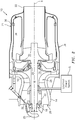
- a static structure 38 of the engine 10 generally includes the forward housing 14, the forward cover 25, a nozzle plate 40, a diffuser 42, a turbine nozzle 44, a combustor liner 46, a combustor housing 48 and the exhaust pipe 22 ( FIG. 3 ).
- the forward cover 25 and the diffuser 42 support a rotational system 50 that includes the rotor shaft 16 and rotational components mounted for rotation therewith.
- the forward cover 25 supports the forward bearing 18 and the diffuser 42 supports the aft bearing 20.
- the static structure 38 is typically manufactured of a metal alloy and may be assembled together by one or more relatively low-cost fastening techniques such as threaded fasteners, welding, v-band clamps, rivets, or the like.
- an additively manufactured thermally insulating structure 100 at least partially surrounds, or forms a portion of, the static structure 38.
- the additively manufactured thermally insulating structure 100 may be additively manufactured integral with the static structure 38 or alternatively separately for later application to the engine 10 in a manner similar to application of a conventional blanket. That is, the additively manufactured thermally insulating structure 100 may be directly additively manufactured into the engine 10.
- the additively manufactured thermally insulating structure 100 is used for the miniature gas turbine engine 10 in the disclosed embodiment, various other applications may benefit from the additively manufactured thermally insulating structure 100.
- the additively manufactured thermally insulating structure 100 includes a base layer 102 and a fire-resistant layer 104 that forms an air gap 106 therebetween.
- the base layer 102 forms the static structure 38 of the engine 10 and the fire-resistant layer 104 is spaced therefrom. That is, the base layer 102 may be that which forms the static structure 38 such that the fire-resistant layer 104 that forms the air gap 106 therebetween is integrated therewith.
- Alloys such as 625 Alloy, 718 Alloy, 230 Alloy, stainless steel, tool steel, cobalt chrome, titanium, nickel, aluminum and others may have specific benefit for environments typically encountered by aerospace and gas turbine engine components such as the base layer 102 and the fire-resistant layer 104.
- the base layer 102 is about 0.1-0.2 inches (about 2.5 - 5 mm) thick
- the fire-resistant layer 104 is about 0.1-0.2 inches (about 2.5 - 5 mm) thick with an about 0.25-0.5 inch thick (about 6-13 mm) air gap 106.
- the base layer 102 and the fire-resistant layer 104 may be additively manufactured of the same or dissimilar material.
- the fire-resistant layer 104 may be additively manufacturing to forms a pattern 114, e.g., a waffle pattern, on an outer surface thereof to facilitate the fire resistance.
- the air gap 106 includes a lattice structure 108.
- the lattice structure 108 forms numerous contiguous "X" shapes, while other examples may utilize other matrix shapes such as triangular shapes. These various matrix shapes provide support between the base layer 102 and the fire-resistant layer 104 yet maintains the air gap 106A.
- the air gap 106 could be an monolithic material that has a low thermal conductivity to provide insulating characteristics.
- the air gap 106B forms an intake 120, a duct 122, and an exhaust 124 to form a bypass duct 136 such that an airflow is passed through the additively manufactured thermally insulating structure 100 to provide active cooling via airflow ( FIG. 8 ).
- the bypass duct 136 may be discrete linear ducts, an integral duct with multiple intakes 120 ( FIG. 9 ) and exhausts 124, or other combinations either with, or without, the lattice structure 108 ( FIG. 7 ).
- a method 200 to install the additively manufactured thermally insulating structure 100 initially includes assembly of the engine 10 (202). Next, the additively manufactured thermally insulating structure 100 is additively manufactured onto the static structure 38 once the engine 10 is assembled (204).
- the additive manufacturing process includes, but is not limited to, Fused deposition modeling (FDM), Stereolithography (SLA), processes using a layer-by-layer UV curing, Selective Laser Sintering (SLS), Electron Beam Sintering (EBS), Electron Beam Melting (EBM), Electron Beam Powder Bed Fusion (EB-PBF), Electron Beam Powder Wire (EBW), Laser Engineered Net Shaping (LENS), Laser Net Shape Manufacturing (LNSM), Direct Metal Deposition (DMD), and Laser Powder Bed Fusion (L-PBF).
- FDM Fused deposition modeling
- SLA Stereolithography
- SLA Stereolithography
- SLA Stereolithography
- SLA Stereolithography
- SLA Stereolithography
- SLA Stereolithography
- SLA Stereolithography
- SLA Stereolithography
- SLA Stereolithography
- SLA Stereolithography
- SLA Stereolithography
- SLA Stereolithography
- SLA Stereolithography
- SLA Stereolithography
- SLA Stereolithography
- the additive manufacturing process sequentially builds-up layers of atomized alloy and/or ceramic powder material that include but are not limited to, 625 Alloy, 718 Alloy, 230 Alloy, stainless steel, tool steel, cobalt chrome, titanium, nickel, aluminum, acrylonitrile butadiene styrene (ABS), nylon, polylactic acid (PLA), polyurethane, urethane, silicone, epoxy, photopolymers that provide rubber-like flexibility, and others in atomized powder material form. That is, the engine 10 may be loaded into the additive manufacturing system and the additively manufactured thermally insulating structure 100 is additively manufactured thereon.
- atomized alloy and/or ceramic powder material that include but are not limited to, 625 Alloy, 718 Alloy, 230 Alloy, stainless steel, tool steel, cobalt chrome, titanium, nickel, aluminum, acrylonitrile butadiene styrene (ABS), nylon, polylactic acid (PLA), polyurethane, urethane, silicone
- a method 300 to install the additively manufactured thermally insulating structure 100 initially includes additively manufacturing the additively manufactured thermally insulating structure 100 onto the static structure 38 (302).
- the forward housing 14, the combustor housing 48 and the exhaust pipe 22 are individually loaded into the additive manufacturing system and the additively manufactured thermally insulating structure 100 is additively manufactured thereon.
- the engine 10 is assembled (304) from the components that have the additively manufactured thermally insulating structure 100 additively manufactured thereon.
- the additively manufactured thermally insulating structure is thus integrated onto each component individually to facilitate assembly and disassembly.
- a method 400 to install the additively manufactured thermally insulating structure 100 initially includes additively manufacturing the static structure 38 (402) as the base layer 102.
- the forward housing 14, the combustor housing 48 and the exhaust pipe 22 are additively manufactured and forms the base layer 102.
- the fire-resistant layer 104 is additively manufactured to the base layer 102 (404) to form the air gap 106 therebetween to form static structure 38 components that have the additively manufactured thermally insulating structure 100 integral therewith.
- the engine 10 is assembled (406) from the components that have the additively manufactured thermally insulating structure 100 additively manufactured thereon.
- the additively manufactured thermally insulating structure is thus integrated onto each component individually to facilitate assembly and disassembly.
- the additively manufactured thermally insulating structure increases the attritable or expendable propulsion systems by, for example, integration of complex performance-enhancing features, lowering production costs, and reducing time to delivery; that are typically prohibitive when leveraging conventional manufacturing techniques.
Landscapes
- Engineering & Computer Science (AREA)
- Chemical & Material Sciences (AREA)
- Combustion & Propulsion (AREA)
- Mechanical Engineering (AREA)
- General Engineering & Computer Science (AREA)
- Manufacturing & Machinery (AREA)
- Materials Engineering (AREA)
- Turbine Rotor Nozzle Sealing (AREA)
- Thermal Insulation (AREA)
Abstract
Description
- The present disclosure relates to additive manufacturing and, more particularly, to an additively manufactured thermally insulating structure for a miniature gas turbine or turbojet engines.
- Miniature gas turbine or turbojet engines that are typically 1000 pound-force (lbf) (4.45 kN) thrust and smaller, are often utilized in attritable or expendable applications such as reconnaissance drones, cruise missiles, decoys, and other applications, including air-launched and ground-launched weapon systems. The use of such single use gas turbine engines greatly extends the range of the air vehicle in comparison to the more conventional solid fuel rocket engine; however, such engines need to be manufactured relatively inexpensively yet provide a high degree of reliability and efficiency.
- The miniature gas turbine is thermally shielded from the vehicle during operation to provide thermal isolation and/or for fire-retardant purposes. A thermal blanket is wrapped around engine components to provide the shielding after assembly of the engine and retained thereto with band clamps. The thermal blanket is typically specialized and requires labor-intensive construction of a combination of fabric, composite, and metallic material layers, which form a compliant structure. Although effective, such blankets are relatively expensive and time consuming to fabricate and install.
- An additively manufactured thermally insulating structure according to one disclosed non-limiting embodiment of the present disclosure includes a base layer; and a fire-resistant layer adjacent to the base layer that forms an air gap therebetween.
- A further embodiment of any of the foregoing embodiments of the present disclosure includes that the base layer forms a static structure of a gas turbine engine.
- A further embodiment of any of the foregoing embodiments of the present disclosure includes that the base layer is 0.1-0.2 inches (about 2.5 - 5 mm) thick and the fire-resistant layer is 0.1-0.2 inches (about 2.5 - 5 mm) thick.
- A further embodiment of any of the foregoing embodiments of the present disclosure includes that the air gap is 0.25-0.5-inch thick (about 6-13 mm).
- A further embodiment of any of the foregoing embodiments of the present disclosure includes a lattice structure within the air gap.
- A further embodiment of any of the foregoing embodiments of the present disclosure includes a duct through the air gap.
- A further embodiment of any of the foregoing embodiments of the present disclosure includes that the duct comprises at least one intake and at least one exhaust.
- A miniature gas turbine engine according to one disclosed non-limiting embodiment of the present disclosure includes a static structure; and an additively manufactured fire-resistant layer additively manufactured to the static structure to form an air gap therebetween.
- A further embodiment of any of the foregoing embodiments of the present disclosure includes that the static structure comprises at least one of a forward housing, a combustor housing, and an exhaust pipe.
- A further embodiment of any of the foregoing embodiments of the present disclosure includes that the fire-resistant layer adjacent forms a pattern which facilitates fire resistance.
- A further embodiment of any of the foregoing embodiments of the present disclosure includes that the fire-resistant layer comprises at least one intake and at least one exhaust.
- A further embodiment of any of the foregoing embodiments of the present disclosure includes that the fire-resistant layer comprises an airflow path.
- A further embodiment of any of the foregoing embodiments of the present disclosure includes that the fire-resistant layer comprises an air gap with a lattice structure.
- A method for assembling a gas turbine engine according to one disclosed non-limiting embodiment of the present disclosure includes additively manufacturing a base layer; and additively manufacturing a fire-resistant layer adjacent to the base layer to form an air gap therebetween.
- A further embodiment of any of the foregoing embodiments of the present disclosure includes that additively manufacturing the base layer comprises additively manufacturing a static structure of the gas turbine engine.
- A further embodiment of any of the foregoing embodiments of the present disclosure includes that additively manufacturing the base layer comprises additively manufacturing at least one of a forward housing, a combustor housing, and an exhaust pipe.
- A further embodiment of any of the foregoing embodiments of the present disclosure includes that additively manufacturing the fire-resistant layer adjacent to the base layer forms an additively manufactured thermally insulating structure.
- A further embodiment of any of the foregoing embodiments of the present disclosure includes assembling the additively manufactured thermally insulating structure onto a static structure of a gas turbine engine.
- A further embodiment of any of the foregoing embodiments of the present disclosure includes additively manufacturing a duct into the air gap
- A further embodiment of any of the foregoing embodiments of the present disclosure includes additively manufacturing a lattice structure into the air gap.
- A further embodiment of any of the foregoing embodiments of the present disclosure includes that the additively manufacturing a fire-resistant layer forms a pattern on an outer surface.
- The foregoing features and elements may be combined in various combinations without exclusivity, unless expressly indicated otherwise. These features and elements as well as the operation thereof will become more apparent in light of the following description and the accompanying drawings. It should be understood, however, the following description and drawings are intended to be exemplary in nature and non-limiting.
- Various features will become apparent to those skilled in the art from the following detailed description of the disclosed non-limiting embodiments. The drawings that accompany the detailed description can be briefly described as follows:
-
FIG. 1 is a general perspective view an exemplary vehicle embodiment for use with a miniature gas turbine engine. -
FIG. 2 is a schematic view of an exemplary miniature gas turbine engine according to one disclosed non-limiting embodiment. -
FIG. 3 is an exploded view of the miniature gas turbine engine. -
FIG. 4 is an exploded view of the miniature gas turbine engine. -
FIG. 5 is an expanded view of an additively manufactured thermally insulating structure for a miniature gas turbine engine. -
FIG. 6 is a sectional view of the additively manufactured thermally insulating structure according to one disclosed non-limiting embodiment. -
FIG. 7 is a sectional view of the additively manufactured thermally insulating structure according to another disclosed non-limiting embodiment. -
FIG. 8 is a longitudinal sectional view of the additively manufactured thermally insulating structure with an active cooling flow path according to another disclosed non-limiting embodiment. -
FIG. 9 is a front view of the additively manufactured thermally insulating structure with a multiple of intakes to the active cooling flow ofFIG. 8 . -
FIG. 10 is a flow chart illustrating a method to install the additively manufactured thermally insulating structure onto a miniature gas turbine engine according to one disclosed non-limiting embodiment. -
FIG. 11 is a flow chart illustrating a method to install the additively manufactured thermally insulating structure onto a miniature gas turbine engine according to one disclosed non-limiting embodiment. -
FIG. 12 is a flow chart illustrating a method to incorporate the additively manufactured thermally insulating structure into a miniature gas turbine engine according to one disclosed non-limiting embodiment. -
FIG. 1 illustrates a general schematic view of an air vehicle V including a miniaturegas turbine engine 10. The air vehicle V may include abody 2 and one or moreaerodynamic surfaces 4. The miniaturegas turbine engine 10 is coupled to, or contained within, thebody 2. Anintake 6 of the air vehicle V provides air to the miniaturegas turbine engine 10 and anexhaust 8 directs the thrust therefrom. - With reference to
FIG. 2 , the miniaturegas turbine engine 10 generally includes ahousing 14, arotor shaft 16 rotationally mounted to aforward bearing 18 and an aft bearing 20, acombustion system 21, and anexhaust pipe 22. Therotor shaft 16 rotates about a longitudinal axis X. In the illustrated rotor configuration, arotor 24 includescompressor blades 26 facing forward toward aninlet 28 andturbine blades 30 facing rearward toward theexhaust pipe 22 to define a turbine wheel on therotor shaft 16. Therotor shaft 16 is received in thebearings fuel pump 32 to provide fuel to anannular combustor liner 34 through afuel manifold 36. Apermanent magnet generator 33 is mounted to therotor shaft 16 to generate electrical power for theengine 10 and other accessories. - With reference also to
FIG. 3 , astatic structure 38 of theengine 10 generally includes theforward housing 14, theforward cover 25, anozzle plate 40, adiffuser 42, aturbine nozzle 44, a combustor liner 46, acombustor housing 48 and the exhaust pipe 22 (FIG. 3 ). Theforward cover 25 and thediffuser 42 support arotational system 50 that includes therotor shaft 16 and rotational components mounted for rotation therewith. Theforward cover 25 supports the forward bearing 18 and thediffuser 42 supports the aft bearing 20. Thestatic structure 38 is typically manufactured of a metal alloy and may be assembled together by one or more relatively low-cost fastening techniques such as threaded fasteners, welding, v-band clamps, rivets, or the like. - With reference to
FIG. 4 , an additively manufactured thermallyinsulating structure 100 at least partially surrounds, or forms a portion of, thestatic structure 38. The additively manufactured thermallyinsulating structure 100 may be additively manufactured integral with thestatic structure 38 or alternatively separately for later application to theengine 10 in a manner similar to application of a conventional blanket. That is, the additively manufactured thermallyinsulating structure 100 may be directly additively manufactured into theengine 10. Although the additively manufactured thermally insulatingstructure 100 is used for the miniaturegas turbine engine 10 in the disclosed embodiment, various other applications may benefit from the additively manufactured thermally insulatingstructure 100. - With reference to
FIG. 5 , the additively manufactured thermally insulatingstructure 100 according to one embodiment includes abase layer 102 and a fire-resistant layer 104 that forms anair gap 106 therebetween. Thebase layer 102 forms thestatic structure 38 of theengine 10 and the fire-resistant layer 104 is spaced therefrom. That is, thebase layer 102 may be that which forms thestatic structure 38 such that the fire-resistant layer 104 that forms theair gap 106 therebetween is integrated therewith. Alloys such as 625 Alloy, 718 Alloy, 230 Alloy, stainless steel, tool steel, cobalt chrome, titanium, nickel, aluminum and others may have specific benefit for environments typically encountered by aerospace and gas turbine engine components such as thebase layer 102 and the fire-resistant layer 104. In one example, thebase layer 102 is about 0.1-0.2 inches (about 2.5 - 5 mm) thick, the fire-resistant layer 104 is about 0.1-0.2 inches (about 2.5 - 5 mm) thick with an about 0.25-0.5 inch thick (about 6-13 mm)air gap 106. Thebase layer 102 and the fire-resistant layer 104 may be additively manufactured of the same or dissimilar material. The fire-resistant layer 104 may be additively manufacturing to forms a pattern 114, e.g., a waffle pattern, on an outer surface thereof to facilitate the fire resistance. - With reference to
FIG 6 , in another disclosed non-limiting embodiment, theair gap 106 includes alattice structure 108. In examples, thelattice structure 108 forms numerous contiguous "X" shapes, while other examples may utilize other matrix shapes such as triangular shapes. These various matrix shapes provide support between thebase layer 102 and the fire-resistant layer 104 yet maintains theair gap 106A. Alternatively, theair gap 106 could be an monolithic material that has a low thermal conductivity to provide insulating characteristics. - With reference to
FIG 7 , in another disclosed non-limiting embodiment, theair gap 106B forms anintake 120, aduct 122, and anexhaust 124 to form a bypass duct 136 such that an airflow is passed through the additively manufactured thermally insulatingstructure 100 to provide active cooling via airflow (FIG. 8 ). The bypass duct 136 may be discrete linear ducts, an integral duct with multiple intakes 120 (FIG. 9 ) and exhausts 124, or other combinations either with, or without, the lattice structure 108 (FIG. 7 ). - With reference to
FIG 10 , amethod 200 to install the additively manufactured thermally insulatingstructure 100 initially includes assembly of the engine 10 (202). Next, the additively manufactured thermally insulatingstructure 100 is additively manufactured onto thestatic structure 38 once theengine 10 is assembled (204). The additive manufacturing process includes, but is not limited to, Fused deposition modeling (FDM), Stereolithography (SLA), processes using a layer-by-layer UV curing, Selective Laser Sintering (SLS), Electron Beam Sintering (EBS), Electron Beam Melting (EBM), Electron Beam Powder Bed Fusion (EB-PBF), Electron Beam Powder Wire (EBW), Laser Engineered Net Shaping (LENS), Laser Net Shape Manufacturing (LNSM), Direct Metal Deposition (DMD), and Laser Powder Bed Fusion (L-PBF). The additive manufacturing process sequentially builds-up layers of atomized alloy and/or ceramic powder material that include but are not limited to, 625 Alloy, 718 Alloy, 230 Alloy, stainless steel, tool steel, cobalt chrome, titanium, nickel, aluminum, acrylonitrile butadiene styrene (ABS), nylon, polylactic acid (PLA), polyurethane, urethane, silicone, epoxy, photopolymers that provide rubber-like flexibility, and others in atomized powder material form. That is, theengine 10 may be loaded into the additive manufacturing system and the additively manufactured thermally insulatingstructure 100 is additively manufactured thereon. - With reference to
FIG. 11 , amethod 300 to install the additively manufactured thermally insulatingstructure 100 according to another disclosed non-limiting embodiment initially includes additively manufacturing the additively manufactured thermally insulatingstructure 100 onto the static structure 38 (302). For example, theforward housing 14, thecombustor housing 48 and theexhaust pipe 22 are individually loaded into the additive manufacturing system and the additively manufactured thermally insulatingstructure 100 is additively manufactured thereon. Next, theengine 10 is assembled (304) from the components that have the additively manufactured thermally insulatingstructure 100 additively manufactured thereon. The additively manufactured thermally insulating structure is thus integrated onto each component individually to facilitate assembly and disassembly. - With reference to
FIG. 12 , amethod 400 to install the additively manufactured thermally insulatingstructure 100 according to another disclosed non-limiting embodiment initially includes additively manufacturing the static structure 38 (402) as thebase layer 102. For example, theforward housing 14, thecombustor housing 48 and theexhaust pipe 22 are additively manufactured and forms thebase layer 102. Next, the fire-resistant layer 104 is additively manufactured to the base layer 102 (404) to form theair gap 106 therebetween to formstatic structure 38 components that have the additively manufactured thermally insulatingstructure 100 integral therewith. - Next, the
engine 10 is assembled (406) from the components that have the additively manufactured thermally insulatingstructure 100 additively manufactured thereon. The additively manufactured thermally insulating structure is thus integrated onto each component individually to facilitate assembly and disassembly. - The additively manufactured thermally insulating structure increases the attritable or expendable propulsion systems by, for example, integration of complex performance-enhancing features, lowering production costs, and reducing time to delivery; that are typically prohibitive when leveraging conventional manufacturing techniques.
- Although the different non-limiting embodiments have specific illustrated components, the embodiments of this invention are not limited to those particular combinations. It is possible to use some of the components or features from any of the non-limiting embodiments in combination with features or components from any of the other non-limiting embodiments.
- It should be appreciated that like reference numerals identify corresponding or similar elements throughout the several drawings. It should also be appreciated that although a particular component arrangement is disclosed in the illustrated embodiment, other arrangements will benefit herefrom.
- Although particular step sequences are shown, described, and claimed, it should be understood that steps may be performed in any order, separated or combined unless otherwise indicated and will still benefit from the present disclosure.
- The foregoing description is exemplary rather than defined by the limitations within. Various non-limiting embodiments are disclosed herein, however, one of ordinary skill in the art would recognize that various modifications and variations in light of the above teachings will fall within the scope of the appended claims. It is therefore to be understood that within the scope of the appended claims, the disclosure may be practiced other than as specifically described. For that reason the appended claims should be studied to determine true scope and content.
Claims (15)
- An additively manufactured thermally insulating structure (100), comprising:abase layer (102); anda fire-resistant layer (104) adjacent to the base layer (102) that forms an air gap (106; 106A; 106B) therebetween.
- The additively manufactured thermally insulating structure (100) as recited in claim 1, wherein the base layer (102) forms a static structure (38) of a gas turbine engine (10).
- The additively manufactured thermally insulating structure (100) as recited in claim 1 or 2, wherein:the base layer (102) is 0.1-0.2 inches (about 2.5 - 5 mm) thick and the fire-resistant layer (104) is 0.1-0.2 inches (about 2.5 - 5 mm) thick; and/orthe air gap (106; 106A; 106B) is 0.25-0.5 inches (about 6-13 mm) thick.
- The additively manufactured thermally insulating structure (100) as recited in any preceding claim, further comprising a lattice structure (108) within the air gap (106A).
- The additively manufactured thermally insulating structure (100) as recited in any preceding claim, further comprising a duct (122) through the air gap (106B), wherein the duct (122) optionally comprises at least one intake (120) and at least one exhaust (124).
- A miniature gas turbine engine (10), comprising:a static structure (38); andan additively manufactured fire-resistant layer (104) additively manufactured to the static structure (38) to form an air gap (106; 106A; 106B) therebetween.
- The miniature gas turbine engine (10) as recited in claim 6, wherein the static structure (38) comprises at least one of a forward housing (14), a combustor housing (48), and an exhaust pipe (22).
- The miniature gas turbine engine (10) as recited in claim 6 or 7, wherein the fire-resistant layer (104) adjacent forms a pattern which facilitates fire resistance.
- The miniature gas turbine engine (10) as recited in any of claims 6 to 8, wherein the fire-resistant layer (104) comprises at least one intake (120) and at least one exhaust (124).
- The miniature gas turbine engine (10) as recited in any of claims 6 to 9, wherein:the fire-resistant layer (104) comprises an airflow path; and/orthe miniature gas turbine engine (10) further comprises a lattice structure (108) within the air gap (106A).
- A method for assembling a gas turbine engine (10), comprising:additively manufacturing a base layer (102); andadditively manufacturing a fire-resistant layer (104) adjacent to the base layer (102) to form an air gap (106; 106A; 106B) therebetween.
- The method as recited in claim 11, wherein additively manufacturing the base layer (102) comprises additively manufacturing a static structure (38) of the gas turbine engine (10), such as at least one of a forward housing (14), a combustor housing (48), and an exhaust pipe (22).
- The method as recited in claim 11 or 12, wherein additively manufacturing the fire-resistant layer (104) adjacent to the base layer (102) forms an additively manufactured thermally insulating structure (100), wherein the method optionally further comprises assembling the additively manufactured thermally insulating structure (100) onto a or the static structure (38) of a gas turbine engine (10).
- The method as recited in any of claims 11 to 13, further comprising additively manufacturing a duct (122), and/or a lattice structure (108) into the air gap (106A).
- The method as recited in any of claims 11 to 14, wherein the additively manufacturing a fire-resistant layer (104) forms a pattern on an outer surface.
Applications Claiming Priority (1)
| Application Number | Priority Date | Filing Date | Title |
|---|---|---|---|
| US16/152,848 US11199136B2 (en) | 2018-10-05 | 2018-10-05 | Additively manufactured thermally insulating structure |
Publications (2)
| Publication Number | Publication Date |
|---|---|
| EP3633155A1 true EP3633155A1 (en) | 2020-04-08 |
| EP3633155B1 EP3633155B1 (en) | 2021-12-01 |
Family
ID=68382108
Family Applications (1)
| Application Number | Title | Priority Date | Filing Date |
|---|---|---|---|
| EP19201790.3A Active EP3633155B1 (en) | 2018-10-05 | 2019-10-07 | Additively manufactured thermally insulating structure |
Country Status (2)
| Country | Link |
|---|---|
| US (1) | US11199136B2 (en) |
| EP (1) | EP3633155B1 (en) |
Families Citing this family (5)
| Publication number | Priority date | Publication date | Assignee | Title |
|---|---|---|---|---|
| US11369985B2 (en) * | 2019-10-04 | 2022-06-28 | Delavan Inc | Fluid conduits with heat shielding |
| FR3110201B1 (en) * | 2020-05-15 | 2022-04-08 | Safran Aircraft Engines | Turbomachine exhaust housing |
| US11268404B2 (en) * | 2020-05-22 | 2022-03-08 | Raytheon Technologies Corporation | Thermal insulation features for gas turbine engines |
| US20230358170A1 (en) * | 2022-05-09 | 2023-11-09 | General Electric Company | Diffuser with passlets |
| US11846249B1 (en) * | 2022-09-02 | 2023-12-19 | Rtx Corporation | Gas turbine engine with integral bypass duct |
Citations (5)
| Publication number | Priority date | Publication date | Assignee | Title |
|---|---|---|---|---|
| US20160290164A1 (en) * | 2015-03-30 | 2016-10-06 | MTU Aero Engines AG | Method for additive manufacturing of a gas turbine casing part |
| FR3040733A1 (en) * | 2015-09-07 | 2017-03-10 | Poly Shape | CARTER FOR ROTATING MACHINES, ESPECIALLY FOR TURBOMACHINES. |
| WO2017212211A1 (en) * | 2016-06-09 | 2017-12-14 | Hieta Technologies Limited | Radial flow turbine heat engine |
| WO2018102075A2 (en) * | 2016-12-02 | 2018-06-07 | General Electric Company | Additive manufactured case with internal passages for active clearance control |
| CN207673439U (en) * | 2017-12-28 | 2018-07-31 | 深圳市华阳新材料科技有限公司 | It is a kind of to use the molding aero-engine of 3D printing |
Family Cites Families (7)
| Publication number | Priority date | Publication date | Assignee | Title |
|---|---|---|---|---|
| DE102007015389B4 (en) | 2006-03-28 | 2013-06-27 | Sitec Industrietechnologie Gmbh | Component and method for its production |
| GB201019287D0 (en) * | 2010-11-15 | 2010-12-29 | Heat engine | |
| GB2493398B (en) | 2011-08-05 | 2016-07-27 | Univ Loughborough | Methods and apparatus for selectively combining particulate material |
| JP2019504237A (en) * | 2015-12-04 | 2019-02-14 | ジェトプテラ、インコーポレイテッド | Micro turbine gas generator and propulsion system |
| US20180001423A1 (en) | 2016-07-01 | 2018-01-04 | General Electric Company | Methods and thin walled reinforced structures for additive manufacturing |
| DE102016115335A1 (en) | 2016-08-18 | 2018-02-22 | Karlsruher Institut für Technologie | MULTI-WALL PIPE COMPONENT AND MANUFACTURING METHOD THEREFOR |
| CN107327045A (en) | 2017-07-10 | 2017-11-07 | 南京嘉翼精密机器制造股份有限公司 | The 3D printing wall of function is reinforced in a kind of band insulation |
-
2018
- 2018-10-05 US US16/152,848 patent/US11199136B2/en active Active
-
2019
- 2019-10-07 EP EP19201790.3A patent/EP3633155B1/en active Active
Patent Citations (5)
| Publication number | Priority date | Publication date | Assignee | Title |
|---|---|---|---|---|
| US20160290164A1 (en) * | 2015-03-30 | 2016-10-06 | MTU Aero Engines AG | Method for additive manufacturing of a gas turbine casing part |
| FR3040733A1 (en) * | 2015-09-07 | 2017-03-10 | Poly Shape | CARTER FOR ROTATING MACHINES, ESPECIALLY FOR TURBOMACHINES. |
| WO2017212211A1 (en) * | 2016-06-09 | 2017-12-14 | Hieta Technologies Limited | Radial flow turbine heat engine |
| WO2018102075A2 (en) * | 2016-12-02 | 2018-06-07 | General Electric Company | Additive manufactured case with internal passages for active clearance control |
| CN207673439U (en) * | 2017-12-28 | 2018-07-31 | 深圳市华阳新材料科技有限公司 | It is a kind of to use the molding aero-engine of 3D printing |
Also Published As
| Publication number | Publication date |
|---|---|
| US11199136B2 (en) | 2021-12-14 |
| US20200109668A1 (en) | 2020-04-09 |
| EP3633155B1 (en) | 2021-12-01 |
Similar Documents
| Publication | Publication Date | Title |
|---|---|---|
| US11199136B2 (en) | Additively manufactured thermally insulating structure | |
| EP3739265B1 (en) | Turbine engine arrangement with monolithic combustor | |
| US10830102B2 (en) | Casing with tunable lattice structure | |
| US7475549B2 (en) | Thermal management system for a gas turbine engine | |
| EP2204539B1 (en) | Stator assembly for a gas turbine engine | |
| EP2794182B1 (en) | Support structure for a gas turbine engine, corresponding gas turbine engine, aeroplane and method of constructing | |
| US7491029B2 (en) | Active clearance control system for gas turbine engines | |
| US10753221B2 (en) | Seal assembly with ductile wear liner | |
| US8262344B2 (en) | Thermal management system for a gas turbine engine | |
| WO2018182807A1 (en) | An additively manufactured mechanical fastener with cooling fluid passageways | |
| EP3663562B1 (en) | Thermal management system for low bypass gas turbine engine | |
| US20090056125A1 (en) | Compressor impellers, compressor sections including the compressor impellers, and methods of manufacturing | |
| EP3633268B1 (en) | Additively manufactured combustor shell with consumable support structures | |
| US10247043B2 (en) | Ducted cowl support for a gas turbine engine | |
| US20080131277A1 (en) | Ball bearing with carbon-carbon cage for gas turbine engines | |
| EP2604804A2 (en) | Fan blade tip clearance control | |
| US20210088215A1 (en) | Casing integrated fluid distribution system | |
| US8438858B1 (en) | Rotational system for an expendable gas turbine engine | |
| US11643969B2 (en) | Split casings and methods of forming and cooling casings | |
| US20230079778A1 (en) | Conformal accessory gearbox for low bypass gas turbine engine | |
| GB2621227A (en) | Build plate integrated into additive manufactured component | |
| CN115962481A (en) | Additive one-piece hole cooled combustor dome |
Legal Events
| Date | Code | Title | Description |
|---|---|---|---|
| PUAI | Public reference made under article 153(3) epc to a published international application that has entered the european phase |
Free format text: ORIGINAL CODE: 0009012 |
|
| STAA | Information on the status of an ep patent application or granted ep patent |
Free format text: STATUS: THE APPLICATION HAS BEEN PUBLISHED |
|
| AK | Designated contracting states |
Kind code of ref document: A1 Designated state(s): AL AT BE BG CH CY CZ DE DK EE ES FI FR GB GR HR HU IE IS IT LI LT LU LV MC MK MT NL NO PL PT RO RS SE SI SK SM TR |
|
| STAA | Information on the status of an ep patent application or granted ep patent |
Free format text: STATUS: REQUEST FOR EXAMINATION WAS MADE |
|
| 17P | Request for examination filed |
Effective date: 20201005 |
|
| RBV | Designated contracting states (corrected) |
Designated state(s): AL AT BE BG CH CY CZ DE DK EE ES FI FR GB GR HR HU IE IS IT LI LT LU LV MC MK MT NL NO PL PT RO RS SE SI SK SM TR |
|
| RAP1 | Party data changed (applicant data changed or rights of an application transferred) |
Owner name: RAYTHEON TECHNOLOGIES CORPORATION |
|
| GRAP | Despatch of communication of intention to grant a patent |
Free format text: ORIGINAL CODE: EPIDOSNIGR1 |
|
| STAA | Information on the status of an ep patent application or granted ep patent |
Free format text: STATUS: GRANT OF PATENT IS INTENDED |
|
| INTG | Intention to grant announced |
Effective date: 20210624 |
|
| GRAS | Grant fee paid |
Free format text: ORIGINAL CODE: EPIDOSNIGR3 |
|
| GRAA | (expected) grant |
Free format text: ORIGINAL CODE: 0009210 |
|
| STAA | Information on the status of an ep patent application or granted ep patent |
Free format text: STATUS: THE PATENT HAS BEEN GRANTED |
|
| AK | Designated contracting states |
Kind code of ref document: B1 Designated state(s): AL AT BE BG CH CY CZ DE DK EE ES FI FR GB GR HR HU IE IS IT LI LT LU LV MC MK MT NL NO PL PT RO RS SE SI SK SM TR |
|
| REG | Reference to a national code |
Ref country code: GB Ref legal event code: FG4D |
|
| REG | Reference to a national code |
Ref country code: AT Ref legal event code: REF Ref document number: 1451955 Country of ref document: AT Kind code of ref document: T Effective date: 20211215 Ref country code: CH Ref legal event code: EP |
|
| REG | Reference to a national code |
Ref country code: IE Ref legal event code: FG4D |
|
| REG | Reference to a national code |
Ref country code: DE Ref legal event code: R096 Ref document number: 602019009689 Country of ref document: DE |
|
| REG | Reference to a national code |
Ref country code: LT Ref legal event code: MG9D |
|
| REG | Reference to a national code |
Ref country code: NL Ref legal event code: MP Effective date: 20211201 |
|
| REG | Reference to a national code |
Ref country code: AT Ref legal event code: MK05 Ref document number: 1451955 Country of ref document: AT Kind code of ref document: T Effective date: 20211201 |
|
| PG25 | Lapsed in a contracting state [announced via postgrant information from national office to epo] |
Ref country code: RS Free format text: LAPSE BECAUSE OF FAILURE TO SUBMIT A TRANSLATION OF THE DESCRIPTION OR TO PAY THE FEE WITHIN THE PRESCRIBED TIME-LIMIT Effective date: 20211201 Ref country code: LT Free format text: LAPSE BECAUSE OF FAILURE TO SUBMIT A TRANSLATION OF THE DESCRIPTION OR TO PAY THE FEE WITHIN THE PRESCRIBED TIME-LIMIT Effective date: 20211201 Ref country code: FI Free format text: LAPSE BECAUSE OF FAILURE TO SUBMIT A TRANSLATION OF THE DESCRIPTION OR TO PAY THE FEE WITHIN THE PRESCRIBED TIME-LIMIT Effective date: 20211201 Ref country code: BG Free format text: LAPSE BECAUSE OF FAILURE TO SUBMIT A TRANSLATION OF THE DESCRIPTION OR TO PAY THE FEE WITHIN THE PRESCRIBED TIME-LIMIT Effective date: 20220301 Ref country code: AT Free format text: LAPSE BECAUSE OF FAILURE TO SUBMIT A TRANSLATION OF THE DESCRIPTION OR TO PAY THE FEE WITHIN THE PRESCRIBED TIME-LIMIT Effective date: 20211201 |
|
| PG25 | Lapsed in a contracting state [announced via postgrant information from national office to epo] |
Ref country code: SE Free format text: LAPSE BECAUSE OF FAILURE TO SUBMIT A TRANSLATION OF THE DESCRIPTION OR TO PAY THE FEE WITHIN THE PRESCRIBED TIME-LIMIT Effective date: 20211201 Ref country code: PL Free format text: LAPSE BECAUSE OF FAILURE TO SUBMIT A TRANSLATION OF THE DESCRIPTION OR TO PAY THE FEE WITHIN THE PRESCRIBED TIME-LIMIT Effective date: 20211201 Ref country code: NO Free format text: LAPSE BECAUSE OF FAILURE TO SUBMIT A TRANSLATION OF THE DESCRIPTION OR TO PAY THE FEE WITHIN THE PRESCRIBED TIME-LIMIT Effective date: 20220301 Ref country code: LV Free format text: LAPSE BECAUSE OF FAILURE TO SUBMIT A TRANSLATION OF THE DESCRIPTION OR TO PAY THE FEE WITHIN THE PRESCRIBED TIME-LIMIT Effective date: 20211201 Ref country code: HR Free format text: LAPSE BECAUSE OF FAILURE TO SUBMIT A TRANSLATION OF THE DESCRIPTION OR TO PAY THE FEE WITHIN THE PRESCRIBED TIME-LIMIT Effective date: 20211201 Ref country code: GR Free format text: LAPSE BECAUSE OF FAILURE TO SUBMIT A TRANSLATION OF THE DESCRIPTION OR TO PAY THE FEE WITHIN THE PRESCRIBED TIME-LIMIT Effective date: 20220302 Ref country code: ES Free format text: LAPSE BECAUSE OF FAILURE TO SUBMIT A TRANSLATION OF THE DESCRIPTION OR TO PAY THE FEE WITHIN THE PRESCRIBED TIME-LIMIT Effective date: 20211201 |
|
| PG25 | Lapsed in a contracting state [announced via postgrant information from national office to epo] |
Ref country code: NL Free format text: LAPSE BECAUSE OF FAILURE TO SUBMIT A TRANSLATION OF THE DESCRIPTION OR TO PAY THE FEE WITHIN THE PRESCRIBED TIME-LIMIT Effective date: 20211201 |
|
| PG25 | Lapsed in a contracting state [announced via postgrant information from national office to epo] |
Ref country code: SM Free format text: LAPSE BECAUSE OF FAILURE TO SUBMIT A TRANSLATION OF THE DESCRIPTION OR TO PAY THE FEE WITHIN THE PRESCRIBED TIME-LIMIT Effective date: 20211201 Ref country code: SK Free format text: LAPSE BECAUSE OF FAILURE TO SUBMIT A TRANSLATION OF THE DESCRIPTION OR TO PAY THE FEE WITHIN THE PRESCRIBED TIME-LIMIT Effective date: 20211201 Ref country code: RO Free format text: LAPSE BECAUSE OF FAILURE TO SUBMIT A TRANSLATION OF THE DESCRIPTION OR TO PAY THE FEE WITHIN THE PRESCRIBED TIME-LIMIT Effective date: 20211201 Ref country code: PT Free format text: LAPSE BECAUSE OF FAILURE TO SUBMIT A TRANSLATION OF THE DESCRIPTION OR TO PAY THE FEE WITHIN THE PRESCRIBED TIME-LIMIT Effective date: 20220401 Ref country code: EE Free format text: LAPSE BECAUSE OF FAILURE TO SUBMIT A TRANSLATION OF THE DESCRIPTION OR TO PAY THE FEE WITHIN THE PRESCRIBED TIME-LIMIT Effective date: 20211201 Ref country code: CZ Free format text: LAPSE BECAUSE OF FAILURE TO SUBMIT A TRANSLATION OF THE DESCRIPTION OR TO PAY THE FEE WITHIN THE PRESCRIBED TIME-LIMIT Effective date: 20211201 |
|
| REG | Reference to a national code |
Ref country code: DE Ref legal event code: R097 Ref document number: 602019009689 Country of ref document: DE |
|
| PG25 | Lapsed in a contracting state [announced via postgrant information from national office to epo] |
Ref country code: IS Free format text: LAPSE BECAUSE OF FAILURE TO SUBMIT A TRANSLATION OF THE DESCRIPTION OR TO PAY THE FEE WITHIN THE PRESCRIBED TIME-LIMIT Effective date: 20220401 |
|
| PLBE | No opposition filed within time limit |
Free format text: ORIGINAL CODE: 0009261 |
|
| STAA | Information on the status of an ep patent application or granted ep patent |
Free format text: STATUS: NO OPPOSITION FILED WITHIN TIME LIMIT |
|
| PG25 | Lapsed in a contracting state [announced via postgrant information from national office to epo] |
Ref country code: DK Free format text: LAPSE BECAUSE OF FAILURE TO SUBMIT A TRANSLATION OF THE DESCRIPTION OR TO PAY THE FEE WITHIN THE PRESCRIBED TIME-LIMIT Effective date: 20211201 Ref country code: AL Free format text: LAPSE BECAUSE OF FAILURE TO SUBMIT A TRANSLATION OF THE DESCRIPTION OR TO PAY THE FEE WITHIN THE PRESCRIBED TIME-LIMIT Effective date: 20211201 |
|
| 26N | No opposition filed |
Effective date: 20220902 |
|
| PG25 | Lapsed in a contracting state [announced via postgrant information from national office to epo] |
Ref country code: SI Free format text: LAPSE BECAUSE OF FAILURE TO SUBMIT A TRANSLATION OF THE DESCRIPTION OR TO PAY THE FEE WITHIN THE PRESCRIBED TIME-LIMIT Effective date: 20211201 |
|
| PG25 | Lapsed in a contracting state [announced via postgrant information from national office to epo] |
Ref country code: MC Free format text: LAPSE BECAUSE OF FAILURE TO SUBMIT A TRANSLATION OF THE DESCRIPTION OR TO PAY THE FEE WITHIN THE PRESCRIBED TIME-LIMIT Effective date: 20211201 Ref country code: IT Free format text: LAPSE BECAUSE OF FAILURE TO SUBMIT A TRANSLATION OF THE DESCRIPTION OR TO PAY THE FEE WITHIN THE PRESCRIBED TIME-LIMIT Effective date: 20211201 |
|
| REG | Reference to a national code |
Ref country code: CH Ref legal event code: PL |
|
| REG | Reference to a national code |
Ref country code: BE Ref legal event code: MM Effective date: 20221031 |
|
| P01 | Opt-out of the competence of the unified patent court (upc) registered |
Effective date: 20230521 |
|
| PG25 | Lapsed in a contracting state [announced via postgrant information from national office to epo] |
Ref country code: LU Free format text: LAPSE BECAUSE OF NON-PAYMENT OF DUE FEES Effective date: 20221007 |
|
| PG25 | Lapsed in a contracting state [announced via postgrant information from national office to epo] |
Ref country code: LI Free format text: LAPSE BECAUSE OF NON-PAYMENT OF DUE FEES Effective date: 20221031 Ref country code: CH Free format text: LAPSE BECAUSE OF NON-PAYMENT OF DUE FEES Effective date: 20221031 |
|
| PG25 | Lapsed in a contracting state [announced via postgrant information from national office to epo] |
Ref country code: BE Free format text: LAPSE BECAUSE OF NON-PAYMENT OF DUE FEES Effective date: 20221031 |
|
| PG25 | Lapsed in a contracting state [announced via postgrant information from national office to epo] |
Ref country code: IE Free format text: LAPSE BECAUSE OF NON-PAYMENT OF DUE FEES Effective date: 20221007 |
|
| PGFP | Annual fee paid to national office [announced via postgrant information from national office to epo] |
Ref country code: GB Payment date: 20230920 Year of fee payment: 5 |
|
| PGFP | Annual fee paid to national office [announced via postgrant information from national office to epo] |
Ref country code: FR Payment date: 20230920 Year of fee payment: 5 |
|
| PGFP | Annual fee paid to national office [announced via postgrant information from national office to epo] |
Ref country code: DE Payment date: 20230920 Year of fee payment: 5 |
|
| PG25 | Lapsed in a contracting state [announced via postgrant information from national office to epo] |
Ref country code: HU Free format text: LAPSE BECAUSE OF FAILURE TO SUBMIT A TRANSLATION OF THE DESCRIPTION OR TO PAY THE FEE WITHIN THE PRESCRIBED TIME-LIMIT; INVALID AB INITIO Effective date: 20191007 |
|
| PG25 | Lapsed in a contracting state [announced via postgrant information from national office to epo] |
Ref country code: CY Free format text: LAPSE BECAUSE OF FAILURE TO SUBMIT A TRANSLATION OF THE DESCRIPTION OR TO PAY THE FEE WITHIN THE PRESCRIBED TIME-LIMIT Effective date: 20211201 |