EP3632827A1 - Cable reel with barrel storage - Google Patents
Cable reel with barrel storage Download PDFInfo
- Publication number
- EP3632827A1 EP3632827A1 EP19306115.7A EP19306115A EP3632827A1 EP 3632827 A1 EP3632827 A1 EP 3632827A1 EP 19306115 A EP19306115 A EP 19306115A EP 3632827 A1 EP3632827 A1 EP 3632827A1
- Authority
- EP
- European Patent Office
- Prior art keywords
- barrel
- reel
- arrangement
- component
- cable
- Prior art date
- Legal status (The legal status is an assumption and is not a legal conclusion. Google has not performed a legal analysis and makes no representation as to the accuracy of the status listed.)
- Withdrawn
Links
Images



Classifications
-
- B—PERFORMING OPERATIONS; TRANSPORTING
- B65—CONVEYING; PACKING; STORING; HANDLING THIN OR FILAMENTARY MATERIAL
- B65H—HANDLING THIN OR FILAMENTARY MATERIAL, e.g. SHEETS, WEBS, CABLES
- B65H75/00—Storing webs, tapes, or filamentary material, e.g. on reels
- B65H75/02—Cores, formers, supports, or holders for coiled, wound, or folded material, e.g. reels, spindles, bobbins, cop tubes, cans, mandrels or chucks
- B65H75/18—Constructional details
- B65H75/22—Constructional details collapsible; with removable parts
- B65H75/2245—Constructional details collapsible; with removable parts connecting flange to hub
-
- B—PERFORMING OPERATIONS; TRANSPORTING
- B65—CONVEYING; PACKING; STORING; HANDLING THIN OR FILAMENTARY MATERIAL
- B65H—HANDLING THIN OR FILAMENTARY MATERIAL, e.g. SHEETS, WEBS, CABLES
- B65H75/00—Storing webs, tapes, or filamentary material, e.g. on reels
- B65H75/02—Cores, formers, supports, or holders for coiled, wound, or folded material, e.g. reels, spindles, bobbins, cop tubes, cans, mandrels or chucks
- B65H75/04—Kinds or types
- B65H75/08—Kinds or types of circular or polygonal cross-section
- B65H75/14—Kinds or types of circular or polygonal cross-section with two end flanges
-
- B—PERFORMING OPERATIONS; TRANSPORTING
- B65—CONVEYING; PACKING; STORING; HANDLING THIN OR FILAMENTARY MATERIAL
- B65H—HANDLING THIN OR FILAMENTARY MATERIAL, e.g. SHEETS, WEBS, CABLES
- B65H75/00—Storing webs, tapes, or filamentary material, e.g. on reels
- B65H75/02—Cores, formers, supports, or holders for coiled, wound, or folded material, e.g. reels, spindles, bobbins, cop tubes, cans, mandrels or chucks
- B65H75/04—Kinds or types
- B65H75/08—Kinds or types of circular or polygonal cross-section
- B65H75/14—Kinds or types of circular or polygonal cross-section with two end flanges
- B65H75/141—Kinds or types of circular or polygonal cross-section with two end flanges covers therefor
-
- B—PERFORMING OPERATIONS; TRANSPORTING
- B65—CONVEYING; PACKING; STORING; HANDLING THIN OR FILAMENTARY MATERIAL
- B65H—HANDLING THIN OR FILAMENTARY MATERIAL, e.g. SHEETS, WEBS, CABLES
- B65H75/00—Storing webs, tapes, or filamentary material, e.g. on reels
- B65H75/02—Cores, formers, supports, or holders for coiled, wound, or folded material, e.g. reels, spindles, bobbins, cop tubes, cans, mandrels or chucks
- B65H75/18—Constructional details
- B65H75/22—Constructional details collapsible; with removable parts
- B65H75/2254—Constructional details collapsible; with removable parts with particular joining means for releasably connecting parts
- B65H75/2263—Discrete fasteners, e.g. bolts or screws
-
- G—PHYSICS
- G02—OPTICS
- G02B—OPTICAL ELEMENTS, SYSTEMS OR APPARATUS
- G02B6/00—Light guides; Structural details of arrangements comprising light guides and other optical elements, e.g. couplings
- G02B6/44—Mechanical structures for providing tensile strength and external protection for fibres, e.g. optical transmission cables
- G02B6/4439—Auxiliary devices
- G02B6/4457—Bobbins; Reels
-
- B—PERFORMING OPERATIONS; TRANSPORTING
- B65—CONVEYING; PACKING; STORING; HANDLING THIN OR FILAMENTARY MATERIAL
- B65H—HANDLING THIN OR FILAMENTARY MATERIAL, e.g. SHEETS, WEBS, CABLES
- B65H2701/00—Handled material; Storage means
- B65H2701/50—Storage means for webs, tapes, or filamentary material
- B65H2701/53—Adaptations of cores or reels for special purposes
- B65H2701/533—Storage compartments for accessories
Definitions
- This application relates to a cable reel. More particularly, this application relates to a cable reel barrel and structure for storing related cable parts within the barrel.
- Copper and fiber cables used in the telecommunication industry are often sold as a combination product/offering that includes both the cable component as well as separate complimentary components.
- These complimentary components may include, for example, bundled electronic/fiber optic equipment, connectors, jacks, plugs, patch panels, termination tools (crimpers, punch down tools, pulling eye, etc%), media converters, enclosures and other such equipment.
- the sale of telecommunication products that include combined cables and equipment present problems regarding packaging, selling, shipping, and installing those products.
- some of these problems relate to the fact that the separate components are typically packaged separately.
- the separate packages i.e. reel and associated equipment boxes forming a two part "parcel"
- Such an arrangement likewise can present issues with the customer's ability to specify and order the correct product.
- some of the rectangular component boxes can be separated from the correct cable reels they are associated with causing delays or even possibly mis-installation.
- PoE extender systems/products are directed to PoE device(s) that are located more than 100m away from the telecommunications closet.
- PoE extender systems may provide a customer a solution involving combinations of a PoE cable on a cable reel and an associated active electronic component that is shipped in a separate protective box. As noted above, they are packed separately, and the aim is to ship together. However, with two separate packages, there are inevitable circumstances where the package is separated from the reel during transit from packaging, storage, sale, shipping, delivery, job site arrival (generally), and ultimately installation.
- the present arrangement looks to overcome the drawbacks associated with the prior art and to provide a combination cable reel and barrel, where the barrel is configured to have a bracket and support system for holding a separable package therein.
- the barrel typically wooden, although possibly made of metal or sturdy plastic, not only acts as a single external carrier for both the cable and the package therein, but it also acts to further protect electronic equipment being shipped in the package stored therein.
- a cable, cable component and reel arrangement includes a cable, at least one component, such as a cable component, configured to be employed in connection with the cable, and a reel, on which the cable is arranged, the reel having a barrel opening.
- the barrel opening includes a plurality of brackets, the brackets are arranged at spaced locations within the barrel opening and configured to support at least one component for storage and shipment.
- a cable reel 10 is shown.
- Cable reel 10 is ideally constructed of wood, but may otherwise be constructed of durable/rigid plastic or metal.
- Reel 10 is essentially constructed of two (2) flanges 12 and a hollow central barrel 14. The width of barrel 14 sets the traverse width of reel 10.
- Reel 10 is typically used for copper wire or fiber optic telecommunication cables, but the present reel 10 may be used in other applications as applicable.
- connection bolts 16 located on both sides of reel 10, couple hollow central barrel 14 and discs 12 to form reel 10.
- a barrel cover 18 may be screwed over a barrel opening 20 with cover screws 22 to form a continuous side panel for reel 10.
- An arbor hole 24 may be arranged in cover 18 for allowing reel 10 to be mounted onto an arbor (not shown) for winding and unwinding of cables thereon.
- cover screws 22 are removed, removing barrel cover 18 and exposing the inside of barrel opening 20.
- brackets 30 are positioned with barrel opening 20 at locations supporting a rectangular package 32 therein.
- brackets 30 may be in the form of L-shaped brackets (e.g. angle iron) constructed from metal or plastic. Each of brackets 30 span at least partially across the internal width of barrel opening 20. In some cases bracket 30 can be nearly the entire width of barrel opening 20, and in some cases may be shorter, possibly spanning only 1 ⁇ 2 the internal width.
- L-shaped brackets e.g. angle iron
- brackets 30 In the arrangement with shorter brackets 30, they would be less expensive, but in the case of longer width brackets 30 they would be able to support thinner-walled package material or no package at all (e.g. bubble wrap applied directly to the item being shipped. This would be similar to the prototype that was built).
- package 32 would typically not be secured directly to brackets 30, but the shape and sizing of package 32 can be such that it would not have a lot of room to move inside the enclosed dimensions of brackets 30 in directions perpendicular to the traverse length.
- a first option shows a close up of angle brackets 30 attached to the inside of barrel opening 20.
- angle bracket 30 is coupled to the inside of barrel opening 20 either using glue, staples, screws or other types of fasteners.
- Brackets 30 In another arrangement as shown in Figure 5 another option shows a close up of angle brackets 30 attached to the inside of barrel opening 20 by coupling to one of barrel connection bolts 16.
- angle bracket 30 is coupled to connection bolts 16.
- bolts 16 may pass through or near the edge of barrel opening 20 in a manner supporting brackets 30.
- brackets 30 may be constructed such that bracket 30 only supports package 32 at its four corners so that the brackets are aligned to easily accept the insertion of package 32.
- Brackets 30 could also be configured such that the circular holes for bolts 16 are between the circular arc of the barrel opening 20 and the lines intersecting at some angle.
- angle bracket 30 is coupled to the inside of barrel opening 20 in the same manner as shown in Figure 5 , but in this arrangement brackets 30 have extended arms 34.
- brackets 30 have extended arms 34.
- Such an arrangement offers more rigidity on one or more sides compared to the others.
- FIG. 7 another option shows a close up of angle brackets 30 attached to the inside of barrel opening 20.
- angle bracket 30 is coupled to the inside of barrel opening 20 in the same manner as shown in either one of Figures 5 or 6 (to the inside of barrel opening 20 or to connection bolts 16, but in this arrangement brackets 30 have extended arms 36 forming a complete rectangular frame 40.
- This arrangement may be used to provide a complete or near complete enclosure within barrel opening 20 to reduce or eliminate the packaging required to the co-shipped components reducing the immediate amount of waste on a jobsite that has to be removed (one less box that has to be broken down, taken to the dumpster and disposed).
- rectangular frame 40 may traverse the entire width of barrel opening 20 or multiple structures 40 could be contained within the traverse width to support the package at multiple locations.
- brackets There could be a bracket 30 (frame part) at each end of each corner of frame 40 or multiple bracket parts 30 could be spaced throughout the traverse width on frame 40 to support the parts packages.
- brackets 30 and the related structures in Figures 3-7 may be used on reel 10 with any number of connection bolts 16 to form any number of cross-sectional shapes, which include but are not limited to squares, rectangles, triangles, circles, ellipses, etc... It is not necessary for all bolts 16 to be used to support brackets 30 or structures 40.
- barrel opening 20 of reel 10 does not have to be circular (i.e. could be rectangular barrel opening 20 (not shown)).
- brackets 30 and structure 40 described above are equally applicable, possibly by welding or gluing such components within said barrel opening 20.
Landscapes
- Physics & Mathematics (AREA)
- General Physics & Mathematics (AREA)
- Optics & Photonics (AREA)
- Packaging Of Annular Or Rod-Shaped Articles, Wearing Apparel, Cassettes, Or The Like (AREA)
- Storage Of Web-Like Or Filamentary Materials (AREA)
Abstract
Description
- This application relates to a cable reel. More particularly, this application relates to a cable reel barrel and structure for storing related cable parts within the barrel.
- Copper and fiber cables used in the telecommunication industry are often sold as a combination product/offering that includes both the cable component as well as separate complimentary components. These complimentary components may include, for example, bundled electronic/fiber optic equipment, connectors, jacks, plugs, patch panels, termination tools (crimpers, punch down tools, pulling eye, etc...), media converters, enclosures and other such equipment.
- The sale of telecommunication products that include combined cables and equipment present problems regarding packaging, selling, shipping, and installing those products. For example, some of these problems relate to the fact that the separate components are typically packaged separately. The separate packages (i.e. reel and associated equipment boxes forming a two part "parcel") increase complexity in stocking and inventory management. Such an arrangement likewise can present issues with the customer's ability to specify and order the correct product. Additionally, during installation on the job site some of the rectangular component boxes can be separated from the correct cable reels they are associated with causing delays or even possibly mis-installation.
- As a specific example, some power over Ethernet (PoE) extender systems/products are directed to PoE device(s) that are located more than 100m away from the telecommunications closet. PoE extender systems may provide a customer a solution involving combinations of a PoE cable on a cable reel and an associated active electronic component that is shipped in a separate protective box. As noted above, they are packed separately, and the aim is to ship together. However, with two separate packages, there are inevitable circumstances where the package is separated from the reel during transit from packaging, storage, sale, shipping, delivery, job site arrival (generally), and ultimately installation.
- The present arrangement looks to overcome the drawbacks associated with the prior art and to provide a combination cable reel and barrel, where the barrel is configured to have a bracket and support system for holding a separable package therein. The barrel, typically wooden, although possibly made of metal or sturdy plastic, not only acts as a single external carrier for both the cable and the package therein, but it also acts to further protect electronic equipment being shipped in the package stored therein.
- To this end, a cable, cable component and reel arrangement includes a cable, at least one component, such as a cable component, configured to be employed in connection with the cable, and a reel, on which the cable is arranged, the reel having a barrel opening. The barrel opening includes a plurality of brackets, the brackets are arranged at spaced locations within the barrel opening and configured to support at least one component for storage and shipment.
- The present invention can be best understood through the following description and accompanying drawing, wherein:
-
Figure 1 is a side view of a cable reel with the barrel cover, in accordance with one embodiment; -
Figure 2 is a front side view of the cable reel ofFigure 1 , in accordance with another embodiment; -
Figure 3 is a side view of a cable reel with the barrel cover removed, in accordance with one embodiment; -
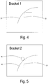
Figure 4 is a close-up view of a barrel bracket used in the barrel ofFigure 1 , in accordance with one embodiment; -
Figure 5 is a close-up view of a barrel bracket used in the barrel ofFigure 1 , in accordance with another embodiment; -
Figure 6 is a close-up view of a barrel bracket used in the barrel ofFigure 1 , in accordance with another embodiment; and -
Figure 7 is a close-up view of a barrel bracket used in the barrel ofFigure 1 , in accordance with another embodiment. - In one embodiment as shown in
Figures 1 and2 , acable reel 10 is shown.Cable reel 10 is ideally constructed of wood, but may otherwise be constructed of durable/rigid plastic or metal.Reel 10 is essentially constructed of two (2)flanges 12 and a hollowcentral barrel 14. The width ofbarrel 14 sets the traverse width ofreel 10.Reel 10 is typically used for copper wire or fiber optic telecommunication cables, but thepresent reel 10 may be used in other applications as applicable. - As shown in
Figure 1 , viewed from the side, one of twoflanges 12 has four (4)connection bolts 16.Connection bolts 16, located on both sides ofreel 10, couple hollowcentral barrel 14 anddiscs 12 to formreel 10. Abarrel cover 18 may be screwed over a barrel opening 20 with cover screws 22 to form a continuous side panel forreel 10. Anarbor hole 24 may be arranged incover 18 for allowingreel 10 to be mounted onto an arbor (not shown) for winding and unwinding of cables thereon. - In one arrangement as shown in
Figure 3 , cover screws 22 are removed, removingbarrel cover 18 and exposing the inside of barrel opening 20. As shown therein fourbrackets 30 are positioned with barrel opening 20 at locations supporting arectangular package 32 therein. - In one embodiment,
brackets 30 may be in the form of L-shaped brackets (e.g. angle iron) constructed from metal or plastic. Each ofbrackets 30 span at least partially across the internal width of barrel opening 20. In somecases bracket 30 can be nearly the entire width of barrel opening 20, and in some cases may be shorter, possibly spanning only ½ the internal width. - In the arrangement with
shorter brackets 30, they would be less expensive, but in the case oflonger width brackets 30 they would be able to support thinner-walled package material or no package at all (e.g. bubble wrap applied directly to the item being shipped. This would be similar to the prototype that was built). - In one embodiment,
package 32 would typically not be secured directly tobrackets 30, but the shape and sizing ofpackage 32 can be such that it would not have a lot of room to move inside the enclosed dimensions ofbrackets 30 in directions perpendicular to the traverse length. - As shown in
Figure 4 a first option shows a close up ofangle brackets 30 attached to the inside of barrel opening 20. In thisarrangement angle bracket 30 is coupled to the inside of barrel opening 20 either using glue, staples, screws or other types of fasteners. - In another arrangement as shown in
Figure 5 another option shows a close up ofangle brackets 30 attached to the inside of barrel opening 20 by coupling to one ofbarrel connection bolts 16. In thisarrangement angle bracket 30 is coupled toconnection bolts 16. For example,bolts 16 may pass through or near the edge of barrel opening 20 in amanner supporting brackets 30. In this arrangement,brackets 30 may be constructed such thatbracket 30 only supportspackage 32 at its four corners so that the brackets are aligned to easily accept the insertion ofpackage 32.Brackets 30 could also be configured such that the circular holes forbolts 16 are between the circular arc of the barrel opening 20 and the lines intersecting at some angle. - As shown in
Figure 6 another option shows a close up ofangle brackets 30 attached to the inside of barrel opening 20. In thisarrangement angle bracket 30 is coupled to the inside of barrel opening 20 in the same manner as shown inFigure 5 , but in thisarrangement brackets 30 have extendedarms 34. Such an arrangement offers more rigidity on one or more sides compared to the others. - As shown in
Figure 7 another option shows a close up ofangle brackets 30 attached to the inside of barrel opening 20. In thisarrangement angle bracket 30 is coupled to the inside of barrel opening 20 in the same manner as shown in either one ofFigures 5 or6 (to the inside of barrel opening 20 or toconnection bolts 16, but in thisarrangement brackets 30 have extendedarms 36 forming a completerectangular frame 40. This arrangement may be used to provide a complete or near complete enclosure within barrel opening 20 to reduce or eliminate the packaging required to the co-shipped components reducing the immediate amount of waste on a jobsite that has to be removed (one less box that has to be broken down, taken to the dumpster and disposed). In some arrangements,rectangular frame 40 may traverse the entire width of barrel opening 20 ormultiple structures 40 could be contained within the traverse width to support the package at multiple locations. The same is true for brackets: There could be a bracket 30 (frame part) at each end of each corner offrame 40 ormultiple bracket parts 30 could be spaced throughout the traverse width onframe 40 to support the parts packages. - Applicants note that
brackets 30 and the related structures inFigures 3-7 may be used onreel 10 with any number ofconnection bolts 16 to form any number of cross-sectional shapes, which include but are not limited to squares, rectangles, triangles, circles, ellipses, etc... It is not necessary for allbolts 16 to be used to supportbrackets 30 orstructures 40. Likewise, it is noted that barrel opening 20 ofreel 10 does not have to be circular (i.e. could be rectangular barrel opening 20 (not shown)). In some cases withreels 10 made without any bolts 16 (i.e.barrel 20 is glued into groves in the inside sides of flanges 12),such brackets 30 andstructure 40 described above are equally applicable, possibly by welding or gluing such components within said barrel opening 20. - While only certain features of the invention have been illustrated, and described herein, many modifications, substitutions, changes or equivalents will now occur to those skilled in the art. It is therefore, to be understood that this application is intended to cover all such modifications and changes that fall within the true spirit of the invention.
Claims (9)
- A cable, component, and reel arrangement comprising:a cable;at least one component; anda reel, on which said cable is arranged, said reel having a barrel opening, said component configured to be stored within said reel,wherein said barrel opening includes a plurality of brackets, said brackets are arranged at spaced locations within said barrel opening and configured to support said at least one component for storage and shipment.
- The arrangement as claimed in claim 1, wherein said at least one component is a cable component configured to be used in connection with said cable.
- The arrangement as claimed in claim 2, wherein said component is selected from the group consisting of bundled electronic/fiber optic equipment, connectors, jacks, plugs, patch panels, termination tools (crimpers, punch down tools, pulling eye, etc...), media converters, enclosures and other such equipment.
- The arrangement as claimed in claim 1, wherein said reel includes two flanges and a hollow central barrel.
- The arrangement as claimed in claim 1, wherein said barrel is covered by a barrel cover.
- The arrangement as claimed in claim 1, wherein said barrel cover includes an arbor hole.
- The arrangement as claimed in claim 1, wherein said flanges are connected to said barrel via connection bolts.
- The arrangement as claimed in claim 7, wherein said barrel of said reel includes a plurality of brackets, each coupled to a connection bolt for supporting said component within said barrel of said reel.
- The arrangement as claimed in claim 1, wherein said barrel of said reel includes a plurality of brackets, each coupled to the inside of said barrel a for supporting said component within said barrel of said reel.
Applications Claiming Priority (1)
| Application Number | Priority Date | Filing Date | Title |
|---|---|---|---|
| US16/149,592 US10696514B2 (en) | 2018-10-02 | 2018-10-02 | Cable reel with barrel storage |
Publications (1)
| Publication Number | Publication Date |
|---|---|
| EP3632827A1 true EP3632827A1 (en) | 2020-04-08 |
Family
ID=68159054
Family Applications (1)
| Application Number | Title | Priority Date | Filing Date |
|---|---|---|---|
| EP19306115.7A Withdrawn EP3632827A1 (en) | 2018-10-02 | 2019-09-17 | Cable reel with barrel storage |
Country Status (3)
| Country | Link |
|---|---|
| US (1) | US10696514B2 (en) |
| EP (1) | EP3632827A1 (en) |
| CA (1) | CA3055799A1 (en) |
Cited By (1)
| Publication number | Priority date | Publication date | Assignee | Title |
|---|---|---|---|---|
| US12221313B2 (en) | 2022-02-28 | 2025-02-11 | Leviton Manufacturing Co., Inc. | Interlocked pay off reel design |
Citations (8)
| Publication number | Priority date | Publication date | Assignee | Title |
|---|---|---|---|---|
| FR2814246A1 (en) * | 2000-09-21 | 2002-03-22 | France Telecom | Over length telecommunications fibre optic cable positioner, has support unit with two winding hub sections producing central cavity positioning zone and cable movement gaps |
| JP2003029053A (en) * | 2001-07-17 | 2003-01-29 | Sumitomo Electric Ind Ltd | Connection box with reel and cable laying method using the same |
| US20100090049A1 (en) * | 2008-10-15 | 2010-04-15 | Lincoln Global, Inc. | Castellated reel core |
| EP2264502A1 (en) * | 2009-06-19 | 2010-12-22 | Nexans | Device for connecting optical fibres |
| CH701475B1 (en) * | 2009-06-08 | 2011-01-31 | Diamond Sa | Arrangement for installing wall socket in living quarters of building, has retaining unit for retaining cable such that cable is pulled from retaining unit, where retaining unit is separated from wall socket and cable after pulling cable |
| WO2013014226A1 (en) * | 2011-07-27 | 2013-01-31 | Tyco Electronics Services Gmbh | Surface-mountable enclosure |
| WO2013130589A1 (en) * | 2012-02-29 | 2013-09-06 | Adc Telecommunications, Inc. | Fiber optic cable packaging arrangement |
| WO2015086043A1 (en) * | 2013-12-10 | 2015-06-18 | Prysmian S.P.A. | Spooling assembly |
Family Cites Families (11)
| Publication number | Priority date | Publication date | Assignee | Title |
|---|---|---|---|---|
| US1861294A (en) * | 1931-03-20 | 1932-05-31 | Oscar L Bartlett | Closure plug for rolls |
| US2393613A (en) * | 1944-05-13 | 1946-01-29 | Us Government | Hand reel |
| US5695148A (en) * | 1996-08-08 | 1997-12-09 | Christensen; Karl Russell | Light string storage reel |
| US20020074462A1 (en) * | 2000-12-14 | 2002-06-20 | Pontecorvo Gary J. | Combination garden hose hanger and storage device |
| US6467623B1 (en) * | 2001-05-24 | 2002-10-22 | John Gordon Lewis | Apparatus for storing strings of lights and accessories |
| US6948680B2 (en) * | 2002-06-18 | 2005-09-27 | Andrew Corporation | Device and method for storing electric cable and electric cable components |
| US6758314B2 (en) * | 2002-10-31 | 2004-07-06 | George Woodruff | Portable light reel system |
| US7252193B1 (en) * | 2003-05-07 | 2007-08-07 | John Gordon Lewis | Storage |
| US7874411B2 (en) * | 2006-10-23 | 2011-01-25 | Corning Cable Systems Llc | Reel for maintaining fiber optic cable assemblies |
| US8074916B2 (en) * | 2008-02-01 | 2011-12-13 | Applied Optical Systems, Inc. | Fiber optic/electrical cable reel assembly |
| US9126800B2 (en) * | 2008-02-01 | 2015-09-08 | Applied Optical Systems, Inc. | Fiber optic/electrical cable reel assembly with cable clip |
-
2018
- 2018-10-02 US US16/149,592 patent/US10696514B2/en active Active
-
2019
- 2019-09-17 EP EP19306115.7A patent/EP3632827A1/en not_active Withdrawn
- 2019-09-18 CA CA3055799A patent/CA3055799A1/en active Pending
Patent Citations (8)
| Publication number | Priority date | Publication date | Assignee | Title |
|---|---|---|---|---|
| FR2814246A1 (en) * | 2000-09-21 | 2002-03-22 | France Telecom | Over length telecommunications fibre optic cable positioner, has support unit with two winding hub sections producing central cavity positioning zone and cable movement gaps |
| JP2003029053A (en) * | 2001-07-17 | 2003-01-29 | Sumitomo Electric Ind Ltd | Connection box with reel and cable laying method using the same |
| US20100090049A1 (en) * | 2008-10-15 | 2010-04-15 | Lincoln Global, Inc. | Castellated reel core |
| CH701475B1 (en) * | 2009-06-08 | 2011-01-31 | Diamond Sa | Arrangement for installing wall socket in living quarters of building, has retaining unit for retaining cable such that cable is pulled from retaining unit, where retaining unit is separated from wall socket and cable after pulling cable |
| EP2264502A1 (en) * | 2009-06-19 | 2010-12-22 | Nexans | Device for connecting optical fibres |
| WO2013014226A1 (en) * | 2011-07-27 | 2013-01-31 | Tyco Electronics Services Gmbh | Surface-mountable enclosure |
| WO2013130589A1 (en) * | 2012-02-29 | 2013-09-06 | Adc Telecommunications, Inc. | Fiber optic cable packaging arrangement |
| WO2015086043A1 (en) * | 2013-12-10 | 2015-06-18 | Prysmian S.P.A. | Spooling assembly |
Cited By (1)
| Publication number | Priority date | Publication date | Assignee | Title |
|---|---|---|---|---|
| US12221313B2 (en) | 2022-02-28 | 2025-02-11 | Leviton Manufacturing Co., Inc. | Interlocked pay off reel design |
Also Published As
| Publication number | Publication date |
|---|---|
| CA3055799A1 (en) | 2020-04-02 |
| US10696514B2 (en) | 2020-06-30 |
| US20200102182A1 (en) | 2020-04-02 |
Similar Documents
| Publication | Publication Date | Title |
|---|---|---|
| US9891399B2 (en) | Packaging assembly for telecommunications components | |
| US6423898B1 (en) | Support member for a cabling and associated equipment enclosure | |
| US5529186A (en) | Boxed pay-out reel for optic fiber cable or wire or the like, with smooth pay-out, high-impact and cable end holding features | |
| US8708144B2 (en) | Adapter for wire dispensing carton | |
| EP2077969B1 (en) | Reel for maintaining fiber optic cable assemblies | |
| US11835780B2 (en) | Cable spool and storage | |
| US20100290752A1 (en) | Vertical cable management system | |
| US20120318939A1 (en) | Tool tray and drafting table for use with cable-containing cartons | |
| US7826707B2 (en) | Cabinet fiber manager | |
| US20100320309A1 (en) | Multiple reel cable carton | |
| US5323479A (en) | Package for fiber optic cable | |
| CN110174737A (en) | Telecommunication assembly | |
| US20090136197A1 (en) | Drumless Cable Reel | |
| US10414622B2 (en) | Fiber reel-in-box cable packaging arrangement | |
| US10696514B2 (en) | Cable reel with barrel storage | |
| US12078860B2 (en) | Fiber optic spool arrangement; and method | |
| US5642812A (en) | Cable and parts container | |
| US11186410B2 (en) | Flexible dynamic packaging of product entities | |
| EP4046950B1 (en) | Cable packaging assembly for storing and unspooling of an electric cable | |
| US20140263814A1 (en) | Cable Assembly Dispenser Systems and Associated Methods | |
| US9701512B2 (en) | Stabilizing center core for stabilizing a coil of duct or cable | |
| US20070221523A1 (en) | Utility and Protective Packaging System | |
| EP4450422B1 (en) | Method and system for handling compressible acoustic panels | |
| CN112083537B (en) | Reel structure for rack-mounted terminal box and rack-mounted terminal box | |
| CN116249655A (en) | Packaging for cable bundles without reel |
Legal Events
| Date | Code | Title | Description |
|---|---|---|---|
| PUAI | Public reference made under article 153(3) epc to a published international application that has entered the european phase |
Free format text: ORIGINAL CODE: 0009012 |
|
| STAA | Information on the status of an ep patent application or granted ep patent |
Free format text: STATUS: THE APPLICATION HAS BEEN PUBLISHED |
|
| AK | Designated contracting states |
Kind code of ref document: A1 Designated state(s): AL AT BE BG CH CY CZ DE DK EE ES FI FR GB GR HR HU IE IS IT LI LT LU LV MC MK MT NL NO PL PT RO RS SE SI SK SM TR |
|
| AX | Request for extension of the european patent |
Extension state: BA ME |
|
| STAA | Information on the status of an ep patent application or granted ep patent |
Free format text: STATUS: REQUEST FOR EXAMINATION WAS MADE |
|
| 17P | Request for examination filed |
Effective date: 20201008 |
|
| RBV | Designated contracting states (corrected) |
Designated state(s): AL AT BE BG CH CY CZ DE DK EE ES FI FR GB GR HR HU IE IS IT LI LT LU LV MC MK MT NL NO PL PT RO RS SE SI SK SM TR |
|
| RAP1 | Party data changed (applicant data changed or rights of an application transferred) |
Owner name: BERK-TEK LLC |
|
| STAA | Information on the status of an ep patent application or granted ep patent |
Free format text: STATUS: EXAMINATION IS IN PROGRESS |
|
| 17Q | First examination report despatched |
Effective date: 20211221 |
|
| STAA | Information on the status of an ep patent application or granted ep patent |
Free format text: STATUS: THE APPLICATION HAS BEEN WITHDRAWN |
|
| 18W | Application withdrawn |
Effective date: 20220421 |