EP3632780B1 - Front vehicle body structure for vehicle and method of forming the same - Google Patents
Front vehicle body structure for vehicle and method of forming the same Download PDFInfo
- Publication number
- EP3632780B1 EP3632780B1 EP19195831.3A EP19195831A EP3632780B1 EP 3632780 B1 EP3632780 B1 EP 3632780B1 EP 19195831 A EP19195831 A EP 19195831A EP 3632780 B1 EP3632780 B1 EP 3632780B1
- Authority
- EP
- European Patent Office
- Prior art keywords
- vehicle
- suspension
- width direction
- vehicle width
- suspension housing
- Prior art date
- Legal status (The legal status is an assumption and is not a legal conclusion. Google has not performed a legal analysis and makes no representation as to the accuracy of the status listed.)
- Active
Links
Images





Classifications
-
- B—PERFORMING OPERATIONS; TRANSPORTING
- B62—LAND VEHICLES FOR TRAVELLING OTHERWISE THAN ON RAILS
- B62D—MOTOR VEHICLES; TRAILERS
- B62D25/00—Superstructure or monocoque structure sub-units; Parts or details thereof not otherwise provided for
- B62D25/08—Front or rear portions
-
- B—PERFORMING OPERATIONS; TRANSPORTING
- B62—LAND VEHICLES FOR TRAVELLING OTHERWISE THAN ON RAILS
- B62D—MOTOR VEHICLES; TRAILERS
- B62D21/00—Understructures, i.e. chassis frame on which a vehicle body may be mounted
-
- B—PERFORMING OPERATIONS; TRANSPORTING
- B62—LAND VEHICLES FOR TRAVELLING OTHERWISE THAN ON RAILS
- B62D—MOTOR VEHICLES; TRAILERS
- B62D21/00—Understructures, i.e. chassis frame on which a vehicle body may be mounted
- B62D21/11—Understructures, i.e. chassis frame on which a vehicle body may be mounted with resilient means for suspension, e.g. of wheels or engine; sub-frames for mounting engine or suspensions
-
- B—PERFORMING OPERATIONS; TRANSPORTING
- B62—LAND VEHICLES FOR TRAVELLING OTHERWISE THAN ON RAILS
- B62D—MOTOR VEHICLES; TRAILERS
- B62D21/00—Understructures, i.e. chassis frame on which a vehicle body may be mounted
- B62D21/15—Understructures, i.e. chassis frame on which a vehicle body may be mounted having impact absorbing means, e.g. a frame designed to permanently or temporarily change shape or dimension upon impact with another body
- B62D21/152—Front or rear frames
-
- B—PERFORMING OPERATIONS; TRANSPORTING
- B60—VEHICLES IN GENERAL
- B60G—VEHICLE SUSPENSION ARRANGEMENTS
- B60G2206/00—Indexing codes related to the manufacturing of suspensions: constructional features, the materials used, procedures or tools
- B60G2206/01—Constructional features of suspension elements, e.g. arms, dampers, springs
- B60G2206/016—Constructional features of suspension elements, e.g. arms, dampers, springs allowing controlled deformation during collision
-
- B—PERFORMING OPERATIONS; TRANSPORTING
- B60—VEHICLES IN GENERAL
- B60R—VEHICLES, VEHICLE FITTINGS, OR VEHICLE PARTS, NOT OTHERWISE PROVIDED FOR
- B60R21/00—Arrangements or fittings on vehicles for protecting or preventing injuries to occupants or pedestrians in case of accidents or other traffic risks
- B60R21/34—Protecting non-occupants of a vehicle, e.g. pedestrians
- B60R2021/343—Protecting non-occupants of a vehicle, e.g. pedestrians using deformable body panel, bodywork or components
-
- B—PERFORMING OPERATIONS; TRANSPORTING
- B62—LAND VEHICLES FOR TRAVELLING OTHERWISE THAN ON RAILS
- B62D—MOTOR VEHICLES; TRAILERS
- B62D25/00—Superstructure or monocoque structure sub-units; Parts or details thereof not otherwise provided for
- B62D25/08—Front or rear portions
- B62D25/082—Engine compartments
-
- B—PERFORMING OPERATIONS; TRANSPORTING
- B62—LAND VEHICLES FOR TRAVELLING OTHERWISE THAN ON RAILS
- B62D—MOTOR VEHICLES; TRAILERS
- B62D25/00—Superstructure or monocoque structure sub-units; Parts or details thereof not otherwise provided for
- B62D25/08—Front or rear portions
- B62D25/088—Details of structures as upper supports for springs or dampers
-
- B—PERFORMING OPERATIONS; TRANSPORTING
- B62—LAND VEHICLES FOR TRAVELLING OTHERWISE THAN ON RAILS
- B62D—MOTOR VEHICLES; TRAILERS
- B62D27/00—Connections between superstructure or understructure sub-units
- B62D27/02—Connections between superstructure or understructure sub-units rigid
Definitions
- the present invention relates to a front vehicle body structure for a vehicle having, at a front part thereof, a pair of suspension housings to which components of a suspension are mounted. Further, the invention relates to a method of forming a front vehicle body structure.
- a suspension housing to which components of a suspension including a damper are mounted is provided.
- the suspension housing is fixed to a front frame extending substantially in a vehicle front-rear direction (e.g., see JP 2011 - 005 882 B ).
- Suspension housings are commonly manufactured by a method of pressing a steel sheet.
- some manufacturers are also considering a method of casting a suspension housing with aluminum (aluminum die casting).
- DE 2016 015 016 A1 discloses a front vehicle body structure and a method of increasing the strength thereof.
- US 2015 / 0 166 108 A1 discloses a front structure arrangement of a vehicle having a pair of side members and a spring tower attached to the side member by means of an attachment means.
- the side members are provided with bend zones and the attachment means is configured to allow a detachment of the spring tower during bending of the side member.
- An object of the present invention is to provide a front vehicle body structure for a vehicle that is capable of both appropriately supporting a suspension and allowing a front frame to deform appropriately.
- the present invention provides a front vehicle body structure for a vehicle including: a pair of front frames provided at a front part of the vehicle and extending substantially in a vehicle front-rear direction; and a pair of suspension housings which are provided at the front part of the vehicle and to which a suspension for a front wheel is mounted or mountable, wherein said suspension housing comprises a first inner wall, a second inner wall and a third inner wall that form the inner side surface in the vehicle width direction of the suspension housing, wherein the suspension housing has a first fixed portion and a second fixed portion that are provided at positions separated from each other in the front-rear direction and each fixed to the front frame, and a buckling promoting portion that is provided substantially at a center portion in the front-rear direction of the third inner wall at a position between the first fixed portion and the second fixed portion in the front-rear direction and has a shape extending substantially in the up-down direction with a bend protruding inward in the vehicle width direction and promotes buckling of the suspension
- the first fixed portion and the second fixed portion of the suspension housing are fixed to the front frame, and the suspension housing and the front frame are firmly fixed to each other.
- the buckling promoting portion that promotes buckling of the suspension housing is provided at a portion between the first fixed portion and the second fixed portion.
- the buckling promoting portion is formed in the inner side surface in the vehicle width direction of the suspension housing and has a shape extending substantially in the up-down direction with a bend protruding inward in the vehicle width direction.
- This buckling promoting portion allows the inner side surface in the vehicle width direction of the suspension housing and, as a consequence, the suspension housing as a whole to buckle more easily in the front-rear direction, and moreover allows this inner side surface in the vehicle width direction and, as a consequence, the suspension housing as a whole to deform inward in the vehicle width direction, thereby preventing the suspension housing from popping out toward a vehicle outer side.
- the suspension housing may have a plurality of arm supporting parts that are provided at positions separated from one another in the front-rear direction and support at least one suspension arm of the suspension, and preferably a bulge that is formed in a region of the inner side surface in the vehicle width direction of the suspension housing, preferably located between the arm supporting parts in the front-rear direction, so as to bulge inward in the vehicle width direction.
- the suspension housing includes a pair of bulges and the buckling promoting portion is provided between the pair of bulges in the front-rear direction.
- the present invention can provide a front vehicle body structure for a vehicle that is capable of both appropriately supporting a suspension and allowing a front frame to deform appropriately.
- a front vehicle body structure for a vehicle comprising the steps of:
- the suspension housing is provided with a plurality of arm supporting parts at positions separated from one another in the front-rear direction so as to support at least one suspension arm of the suspension, and preferably with at least one bulge that is formed in a region of the inner side surface in the vehicle width direction of the suspension housing, preferably located between the arm supporting parts in the front-rear direction, so as to bulge inward in the vehicle width direction.
- the suspension housing includes a plurality of bulges separated from one another in the vehicle front-rear direction.
- the suspension housing is formed with a pair of bulges and the buckling promoting portion is provided between the pair of bulges in the front-rear direction.
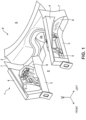
- FIG. 1 is a perspective view schematically showing the structure of a front vehicle body 1 of a vehicle V according to the present invention.
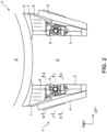
- FIG. 2 is a top view schematically showing the structure of the front vehicle body 1 of the vehicle V.
- FIG. 3 is a side view schematically showing part of the front vehicle body 1 of the vehicle V.
- FIG. 3 is a view of part of a right-side part, with the viewing direction oriented frontward, of the front vehicle body 1 of the vehicle V as seen from an outer side in a vehicle width direction.
- a front-rear direction of the vehicle will be referred to simply as a front-rear direction, and where appropriate, the vehicle width direction will be referred to as a right-left direction.
- Right and left with the viewing direction oriented frontward will be referred to simply as right and left.
- in means an inner side in the vehicle width direction
- out means an outer side in the vehicle width direction.
- a dashboard panel 2 is provided that forms a front end portion of a vehicle cabin S and defines an engine compartment E (a part where an engine unit (not shown) composed of an engine, a transmission, etc. is installed) and the vehicle cabin S.
- the dashboard panel 2 is a panel extending substantially in an up-down direction and the vehicle width direction.
- the vehicle V is a front-engine, rear-wheel-drive vehicle (so-called FR vehicle) configured such that an output of the engine installed at the front part is transmitted to the rear wheels, and a tunnel 2a through which a propeller shaft is passed is formed at a center in the vehicle width direction of the dashboard panel 2.
- front frames 3, apron reinforcements 4, and suspension housings 5 are provided.
- coupling panels 6 each interposed between the suspension housing 5 and the dashboard panel 2 are provided.
- the front frames 3, the apron reinforcements 4, the suspension housings 5, and the coupling panels 6 are right and left pairs of vehicle body constituent members.
- suspensions 10 are provided.
- the suspensions 10 are respectively provided on the right and left sides so as to correspond to a right and left pair of front wheels. The suspensions 10 are not shown in FIG. 1 and FIG. 2 .
- the front structure of the vehicle V is symmetrical in the right-left direction, and therefore the structure on one of the right and left sides will be described below.
- the apron reinforcement 4 is a reinforcement member extending substantially in the front-rear direction.
- the apron reinforcement 4 extends substantially frontward from a hinge pillar 7 to which a hinge of a front door of the vehicle is mounted.
- a front part of the apron reinforcement 4 independently forms a substantially closed cross-sectional part extending substantially in the front-rear direction, while a rear part of the apron reinforcement 4 forms a substantially closed cross-sectional part extending substantially in the front-rear direction together with the suspension housing 5 as will be described later.
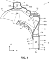
- FIG. 4 is a schematic view showing a close-up of section IV-IV of FIG. 2 .
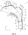
- FIG. 5 is a schematic view showing a close-up of section V-V of FIG. 2 .
- FIG. 6 is a schematic view showing a close-up of section VI-VI of FIG. 2 .
- the front frame 3 is a vehicle body rigid member that forms a substantially closed cross-sectional part C1 extending substantially in the front-rear direction.
- the front frame 3 is fixed to the dashboard panel 2 and extends substantially frontward from the dashboard panel 2.
- the front frame 3 is disposed at a position below the apron reinforcement 4 and on the inner side in the vehicle width direction of the apron reinforcement 4.
- the right front frame 3 is disposed at a position in a direction of about 45 degrees toward an obliquely lower left side relative to the right apron reinforcement 4.
- Between the apron reinforcement 4 and the front frame 3 is provided a space in which a wheel well WH to cover a front wheel (not shown) can be formed.
- the substantially closed cross-sectional part C1 has a substantially rectangular parallelepiped shape elongated in the up-down direction
- the front frame 3 has: a first side surface part 3a extending substantially in the up-down direction and the substantially front-rear direction and forming an outer side surface in the vehicle width direction of the front frame 3; an upper surface part 3b extending substantially inward in the vehicle width direction from an upper edge of the first side surface part 3a and forming an upper surface of the front frame 3; a lower surface part 3c extending substantially inward in the vehicle width direction from a lower edge of the first side surface part 3a and forming a lower surface of the front frame 3; and a second side surface part 3d extending substantially in the up-down direction between an inner edge in the vehicle width direction of the upper surface part 3b and an inner edge in the vehicle width direction of the lower surface part 3c and forming an inner side surface in the vehicle width direction of the front frame 3.
- the front frame 3 further includes an upper flange 3e extending substantially upward from near the inner edge in the vehicle width direction of the upper surface part 3b, i.e., the upper surface of the front frame 3, and a lower flange 3f extending substantially downward from near the inner edge in the vehicle width direction of the lower surface part 3c, i.e., the lower surface of the front frame 3.
- the upper flange 3e and the lower flange 3f extend substantially in the front-rear direction along the entire length of the front frame 3.
- Each front frame 3 is made of a sheet-shaped steel material, for example, and is formed by joining together three members: a front frame outer part 3s with a substantially hat-shaped cross-section that is provided on the outer side in the vehicle width direction and protrudes outward in the vehicle width direction; a front frame inner part 3t with a substantially hat-shaped cross-section that is provided on the inner side in the vehicle width direction and protrudes slightly inward in the vehicle width direction; and a plate-shaped flange forming panel 3u that is interposed between the front frame outer part 3s and the front frame inner part 3t and extends substantially in the up-down direction.
- the upper flange 3e formed as a flange portion formed in the front frame outer part 3s, an upper end portion of the flange forming panel 3u, and a flange portion formed in the front frame inner part 3t are joined together.
- the front frame 3 is configured to deform when the vehicle collides and an impact is exerted on the front frame 3 in the vehicle front-rear direction and thereby restrain this impact from being transmitted to the vehicle cabin S.
- the front frame 3 buckles at a plurality of points, so that the impact force is restrained from being transmitted through the front frame 3 to the dashboard panel 2 and eventually to the inside of the vehicle cabin S.
- a double-wishbone suspension is used as the suspension 10.
- the suspension 10 includes: a knuckle (not shown) fixed to a tire (not shown); a lower arm (not shown) coupled to the knuckle and supporting the tire through the knuckle; an upper arm 12 (so-called A-arm) disposed above the lower arm and, like the lower arm, coupled to the knuckle and supporting the tire through the knuckle; and a damper 11.
- the damper 11 includes a shock absorber 11a and a coil spring 11b installed so as to surround an outer periphery of the shock absorber 11a.
- the upper arm 12 corresponds to the "suspension arm" in the claims.
- FIG. 7 is a schematic perspective view of part of the right-side part of the front vehicle body 1 of the vehicle V as seen from an obliquely lower right side.
- the damper 11 is omitted from FIG. 7 as compared with FIG. 3 .
- the upper arm 12 has a knuckle fixing portion 12a to which an upper end of the knuckle is fixed.
- the knuckle fixing portion 12a is provided at an outermost end in the vehicle width direction of the upper arm 12, and the upper arm 12 includes a first arm 13 extending from the knuckle fixing portion 12a while curving frontward and inward in the vehicle width direction, and a second arm 14 extending from the knuckle fixing portion 12a while curving rearward and inward in the vehicle width direction.
- a first pivotally supported portion 13a and a second pivotally supported portion 14a each pivotally supported by the suspension housing 5 are provided at an inner end in the vehicle width direction of the first arm 13 and an inner end in the vehicle width direction of the second arm 14, respectively.
- the first pivotally supported portion 13a and the second pivotally supported portion 14a are fixed to the suspension housing 5 so as to be able to rotate around an axis extending substantially in the front-rear direction, and the upper arm 12 is supported by the suspension housing 5 so as to be able to turn in the up-down direction around a rotational central axis of these pivotally supported portions 13a, 14a.
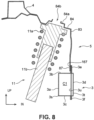
- the damper 11 is supported by the suspension housing 5 and the lower arm in a posture in which the damper 11 extends substantially in the up-down direction. More particularly, a lower end portion of the damper 11 is supported by the lower arm while an upper end portion of the damper 11 is supported by the suspension housing 5. As shown in FIG. 3 , the damper 11 is supported in a rearward tilted posture in which the damper 11 is inclined toward an obliquely upper rear side (i.e., a posture in which the upper side of the damper 11 is located farther on the rear side than the lower side). Moreover, as shown in FIG. 8 that is a schematic view of section VIII-VIII of FIG.
- the damper 11 is supported in an inward tilted posture in which the damper 11 is inclined toward an obliquely upper inner side (i.e., a posture in which the upper side of the damper 11 is located farther on the inner side in the vehicle width direction than the lower side).
- the suspension housing 5 is a member to which components of the suspension 10 are mounted. As described above, the upper end portion of the damper 11 and the pivotally supported portions 13a, 14a of the upper arm 12 are mounted to the suspension housing 5.
- the suspension housing 5 has a shape of a housing that houses the damper 11 and opens at a lower end, and is fixed to the front frame 3 and the apron reinforcement 4 so as to cover the upper side of the wheel well WH.
- the front frame 3 is disposed below the apron reinforcement 4 and on the inner side in the vehicle width direction of the apron reinforcement 4. Accordingly, the suspension housing 5 as a whole has a shape extending from the apron reinforcement 4 toward the front frame 3 in a direction downward and inward in the vehicle width direction, and bridges a space between these members.
- a rear end portion of the suspension housing 5 is further fixed to the coupling panel 6.
- the coupling panel 6 is a panel member, of which a rear part extends substantially horizontally while a front part is inclined toward an obliquely upper front side such that the front side of the front part is located farther on the upper side than the rear side thereof.
- the coupling panel 6 is fixed to the dashboard panel 2 so as to extend frontward from the dashboard panel 2.
- the suspension housing 5 is coupled to the dashboard panel 2 through the front frame 3 and the coupling panel 6.
- An outer edge in the vehicle width direction of the coupling panel 6 is further fixed to the hinge pillar 7.
- the suspension housing 5 in this embodiment is a lightweight, intricately shaped suspension housing 5.
- the suspension housing 5 may be formed by performing press-working etc. on a metal sheet member.
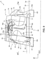
- FIG. 9 is a schematic side view of the suspension housing 5 alone as seen from the inner side in the vehicle width direction.
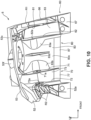
- FIG. 10 is a schematic side view of the suspension housing 5 alone as seen from the outer side in the vehicle width direction.
- FIG. 11 is a schematic top view of the suspension housing 5 alone.
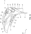
- FIG. 12 is a schematic front view of the suspension housing 5 alone.
- FIG. 13 is a schematic view of section XIII-XIII of FIG. 9 .
- the suspension housing 5 is roughly composed of a suspension fixing section 51 which is a part of the suspension housing 5 except for the rear end portion and an outer portion in the vehicle width direction and to which the suspension 10 is fixed; a rear coupling section 52 extending substantially rearward from the suspension fixing section 51 and forming the rear end portion of the suspension housing 5; and an outer coupling section 53 extending substantially outward in the vehicle width direction from the suspension fixing section 51 and the rear coupling section 52 and forming the outer portion in the vehicle width direction of the suspension housing 5.
- These sections 51, 52, 53 are integrally formed.
- the suspension fixing section 51 includes: a first arm supporting part 60 forming a front end part of the suspension fixing section 51; a second arm supporting part 70 forming a rear end part of the suspension fixing section 51; and a main part 80 forming a part between the first arm supporting part 60 and the second arm supporting part 70.
- the first arm supporting part 60 and the second arm supporting part 70 correspond to the "arm supporting parts" in the claims.
- the first arm supporting part 60 is a part that supports the first arm 13 of the upper arm 12.
- the first arm supporting part 60 includes: a first upright wall 61 extending substantially in the up-down direction and the vehicle width direction; a second upright wall 62 extending substantially parallel to the first upright wall 61 on the rear side of the first upright wall 61; a first inner wall 63 extending substantially in the up-down direction and the front-rear direction between an inner edge in the vehicle width direction of the first upright wall 61 and an inner edge in the vehicle width direction of the second upright wall 62; and a first upper wall 64 extending substantially in the vehicle width direction and the front-rear direction between an upper edge of the first upright wall 61 and an upper edge of the second upright wall 62.
- These walls 61 to 64 of the first arm supporting part 60 form an open cross-sectional part opening outward in the vehicle width direction.
- an "open cross-section” as termed in this specification refers not to a cross-section that is fully closed or closed with a slight opening left therein by a plate member like the closed cross-sectional part C1, but to a cross-section with an opening that is formed by a plurality of bends so as to protrude into a prism shape, V-shape, etc. relative to a flat surface.
- the first arm supporting part 60 further includes: a front extension portion 65 extending substantially frontward from a front surface of the first upright wall 61; a front flange 66 extending substantially downward from a front edge of the front extension portion 65; and a first fixed portion 67 extending substantially downward from the front extension portion 65 and the first inner wall 63.
- the first upper wall 64 forms part of a top surface of the suspension housing 5.
- the first upper wall 64 extends from the upper edge of the first inner wall 63 outward in the vehicle width direction, to a position on the outer side in the vehicle width direction of the first upright wall 61 and the second upright wall 62.
- the first inner wall 63 forms part of an inner side surface in the vehicle width direction of the suspension housing 5. As shown in FIG. 4 etc., an upper part of the first inner wall 63 extends substantially vertically, while a lower part of the first inner wall 63 is inclined so as to be located farther on the outer side in the vehicle width direction as it extends substantially downward.
- the first upright wall 61, the front extension portion 65, and the front flange 66 form part of a front end portion of the suspension housing 5.
- a space between the front extension portion 65 and the first upright wall 61 is bridged by a plurality of ribs R1, and the rigidity of the first upright wall 61 is enhanced by the front extension portion 65 and these ribs R1.
- a plurality of ribs are provided also on a lower surface of the front extension portion 65, and the rigidity of the front extension portion 65 and, as a consequence, the rigidity of the first upright wall 61 is thereby enhanced.
- the length in the vehicle width direction of the second upright wall 62 is set to be shorter than the length in the vehicle width direction of the first upright wall 61.
- the second upright wall 62 has such a shape that the dimension in the vehicle width direction increases toward the upper side.
- the first upright wall 61 and the second upright wall 62 have shaft holes 61a, 62a which are formed substantially at centers in the up-down direction of these upright walls and through which a shaft member for pivotally supporting the first arms 13 is inserted.
- the first pivotally supported portion 13a of the first arm 13 is housed between the first upright wall 61 and the second upright wall 62.
- the shaft member extending substantially in the front-rear direction is passed through a hole (not shown) formed in the first pivotally supported portion 13a and the shaft holes 61a, 62a of the upright walls 61, 62, and this shaft member is fixed to the second upright wall 62, so that the first arm 13 is supported by the first arm supporting part 60 so as to be able to turn substantially in the up-down direction.
- the shaft member and, as a consequence, the first arm 13 are fixed on the rear side of the second upright wall 62.
- a fixing member for fixing the shaft member is attached to the shaft member on the rear side of the second upright wall 62, and the fixing member and the shaft member are fixed to the second upright wall 62 with a tool on the rear side of the second upright wall 62.
- the second arm supporting part 70 is a part that supports the second arm 14 of the upper arm 12.
- the second arm supporting part 70 includes: a third upright wall 71 extending substantially parallel to the second upright wall 62 (i.e., extending in the up-down direction and the vehicle width direction) on the rear side of the second upright wall 62; a fourth upright wall 72 extending substantially parallel to the third upright wall 71 (i.e., extending in the up-down direction and the vehicle width direction) on the rear side of the third upright wall 71; a second inner wall 73 extending in the up-down direction and the front-rear direction between an inner edge in the vehicle width direction of the third upright wall 71 and an inner edge in the vehicle width direction of the fourth upright wall 72; and a second upper wall 74 extending in the vehicle width direction and the front-rear direction between an upper edge of the third upright wall 71 and an upper edge of the fourth upright wall 72.
- These walls 71 to 74 of the second arm supporting part 70 form an open cross-sectional part opening outward in the vehicle width direction.
- the second arm supporting part 70 further includes a second fixed portion 77 extending substantially downward from the second inner wall 73.
- the second upper wall 74 forms part of the top surface of the suspension housing 5.
- the second upper wall 74 extends outward in the vehicle width direction from the upper edge of the second inner wall 73 while being slightly inclined such that the outer side in the vehicle width direction of the second upper wall 74 is located farther on the upper side than the inner side in the vehicle width direction thereof.
- the second inner wall 73 forms part of the inner side surface in the vehicle width direction of the suspension housing 5. As with the first inner wall 63, an upper part of the second inner wall 73 extends substantially vertically, while a lower part of the second inner wall 73 is inclined so as to be located farther on the outer side in the vehicle width direction as it extends downward.
- the third upright wall 71 has such a shape that the dimension in the vehicle width direction increases toward the upper side.
- the third upright wall 71 extends farther outward in the vehicle width direction than the second upright wall 62.
- the fourth upright wall 72 extends farther outward in the vehicle width direction than the first, second, and third upright walls 61, 62, 71, and the dimension in the vehicle width direction of the fourth upright wall 72 is larger than that of the other upright walls.
- the fourth upright wall 72 is connected to the rear coupling section 52 having a plurality of ribs R2 formed on a lower surface thereof.
- the second arm supporting part 70 has higher rigidity than the first arm supporting part 60 in this embodiment.
- the third upright wall 71 and the fourth upright wall 72 have shaft holes 71a, 72a, respectively, which are formed substantially at the center in the up-down direction of the third upright wall 71 and substantially at the center in the up-down direction of inner part in the vehicle width direction of the fourth upright wall 72 and into which a shaft member for pivotally supporting the second arm 14 is inserted.
- the second pivotally supported portion 14a of the second arm 14 is housed between the third upright wall 71 and the fourth upright wall 72.
- the shaft member extending substantially in the front-rear direction is passed through a hole (not shown) formed in the second pivotally supported portion 14a and the shaft holes 71a, 72a of the upright walls 71, 72, and this shaft member is fixed to the third upright wall 71, so that the second arm 14 is supported by the second arm supporting part 70 so as to be able to turn in the up-down direction.
- the shaft member and, as a consequence, the second arm 14 are fixed on the front side of the third upright wall 71.
- a fixing member for fixing the shaft member is attached to the shaft member on the front side of the third upright wall 71, and the fixing member and the shaft member are fixed to the third upright wall 71 with a tool on the front side of the third upright wall 71.
- the levels of the shaft holes 71a, 72a formed in the third upright wall 71 and the fourth upright wall 72 are lower than the levels of the shaft holes 61a, 62a formed in the first upright wall 61 and the second upright wall 62. Accordingly, the upper arm 12 is supported by the suspension housing 5 in a posture in which the upper arm 12 is inclined toward an obliquely lower rear side as seen in a side view, with the second pivotally supported portion 14a of the second arm 14 located at a lower level than the first pivotally supported portion 13a of the first arm 13.
- the main part 80 includes a third upper wall 84 extending in the vehicle width direction and the front-rear direction between the first upper wall 64 and the second upper wall 74, and a third inner wall 83 extending substantially vertically downward from an inner edge in the vehicle width direction of the third upper wall 84.
- the third upper wall 84 is inclined such that the inner side in the vehicle width direction of the third upper wall 84 is located farther on the lower side than the outer side in the vehicle width direction thereof.
- the third upper wall 84 has a damper fixing portion 84a to which the upper end portion of the damper 11 is fixed.
- the damper fixing portion 84a protrudes substantially upward substantially at a center of the third upper wall 84, and has a substantially disc shape with a through-hole 84b formed at a center as seen in a top view. As shown in FIG.
- the damper 11 is housed between the second upright wall 62 and the third upright wall 71 as seen in a side view, and is fixed to the damper fixing portion 84a with the upper end portion of the damper 11 passed through the through-hole 84b of the damper fixing portion 84a.
- a plurality of ribs R3 extending substantially in the up-down direction are formed around the damper fixing portion 84a, and the rigidity of the damper fixing portion 84a is enhanced by these ribs R3.
- the main part 80 further includes a third fixed portion 87 extending substantially downward from the third inner wall 83.
- the third fixed portion 87 and the second fixed portion 77 are continuous with each other in the front-rear direction, and these fixed portions 77, 87 have a form of a flat surface extending substantially in the front-rear direction.
- the fixed portions 77, 87 are formed such that inner side surfaces and outer side surfaces in the vehicle width direction thereof are continuous with each other and form a flat surface extending substantially in the front-rear direction.
- the levels of a lower edge of the third fixed portion 87 and a lower edge of the second fixed portion 77 are higher than the level of a lower edge of the first fixed portion 67. In other words, the first fixed portion 67 extends farther downward than the third fixed portion 87 and the second fixed portion 77.
- the third inner wall 83 extends basically in the vertical direction. However, a part of the third inner wall 83 that is continuous with the second upright wall 62 and a part thereof that is continuous with the third upright wall 71 partially bulge inward in the vehicle width direction. Specifically, as shown in FIG. 10 , FIG. 13 , etc., a portion of a front-side part of the third inner wall 83 that surrounds the shaft hole 62a of the second upright wall 62 as seen in a side view is curved so as to bulge inward in the vehicle width direction while extending frontward from a portion 83c that is located at a center in the front-rear direction of the third inner wall 83 and extends substantially vertically.
- This bulging portion forms a front bulge 83a bulging inward in the vehicle width direction.
- a portion of a rear-side part of the third inner wall 83 that surrounds the shaft hole 71a of the third upright wall 71 as seen in a side view is curved so as to bulge inward in the vehicle width direction while extending substantially rearward from the center portion 83c in the front-rear direction of the third inner wall 83.
- This bulging portion forms a rear bulge 83b bulging inward in the vehicle width direction.
- the front bulge 83a and the rear bulge 83b thus configured correspond to the "bulges" in the claims.
- a buckling promoting portion 83d that promotes buckling of the suspension housing 5 in the front-rear direction is provided in the portion 83c of the third inner wall 83 between the front bulge 83a and the rear bulge 83b. More particularly, the buckling promoting portion 83d is provided substantially at a center portion in the front-rear direction of the third inner wall 83 that forms the inner side surface in the vehicle width direction of the suspension housing 5, and has a shape extending substantially in the up-down direction with a bend protruding inward in the vehicle width direction. In this embodiment, the buckling promoting portion 83d is formed as a portion of the third inner wall 83 and is pushed out so as to project inward in the vehicle width direction with a constant plate thickness.
- the suspension housing 5 is configured to buckle from the buckling promoting portion 83d as a starting point when a load equal to or larger than a predetermined load is applied to the suspension housing 5 through the front frame 3 in the front-rear direction as a result of a collision of the vehicle. Since the buckling promoting portion 83d projects inward in the vehicle width direction in this embodiment, the third inner wall 83 deforms so as to bend inward in the vehicle width direction from the buckling promoting portion 83d as the center.
- the rear coupling section 52 extends substantially rearward from a rear surface of the fourth upright wall 72.
- the rear coupling section 52 is shaped so as to be curved downward and inward in the vehicle width direction.
- a plurality of ribs R4 extending so as to connect the rear surface of the fourth upright wall 72 and an upper surface of the rear coupling section 52 to each other are provided, and the rigidity of the fourth upright wall 72 and the rear coupling section 52 is enhanced by these ribs R4.
- the ribs R2 are provided in a lattice pattern on the lower surface of the rear coupling section 52, and the rigidity of the rear coupling section 52 and the rigidity of the fourth upright wall 72 continuous with the rear coupling section 52 are enhanced also by these ribs R2.
- a lower end portion of the rear coupling section 52 extends substantially in the up-down direction and functions as a fourth fixed portion 52a.
- the fourth fixed portion 52a is also an inner end in the vehicle width direction of the rear coupling section 52.
- the fourth fixed portion 52a extends to a level substantially equivalent to that of the first fixed portion 67, and extends farther downward than the third fixed portion 87 and the second fixed portion 77.
- the outer coupling section 53 extends outward in the vehicle width direction from inner edges in the vehicle width direction of the first upper wall 64, the second upper wall 74, the third upper wall 84, and the rear coupling section 52.
- a step is formed in the outer coupling section 53 such that an outer part in the vehicle width direction of the outer coupling section 53 is located below an inner part in the vehicle width direction thereof.
- the outer coupling section 53 includes: a first lateral wall 53b forming the outer part in the vehicle width direction and extending in the vehicle width direction and the front-rear direction; a rising wall 53c extending substantially upward from an inner edge in the vehicle width direction of the first lateral wall 53b; and a second lateral wall 53d extending substantially inward in the vehicle width direction from an upper edge of the rising wall 53c.
- the first lateral wall 53b extends substantially horizontally, while the second lateral wall 53d is slightly inclined toward an obliquely lower inner side such that the inner side in the vehicle width direction of the second lateral wall 53d is located farther on the lower side than the outer side in the vehicle width direction thereof.
- the suspension housing 5 is disposed such that the outer coupling section 53 abuts against the apron reinforcement 4 from the lower side, and the suspension housing 5 is fixed to the apron reinforcement 4 at the outer coupling section 53.
- a substantially closed cross-sectional part C2 extending substantially in the front-rear direction is formed between the apron reinforcement 4 and an upper surface of the outer coupling section 53.
- a recessed portion 53f protruding substantially upward is provided substantially at a center portion in the front-rear direction of the first lateral wall 53b.
- the recessed portion 53f protrudes substantially outward in the vehicle width direction from the rising wall 53c.
- the recessed portion 53f has a semicircular shape protruding substantially outward in the vehicle width direction from the rising wall 53c. This shape of the recessed portion 53f substantially corresponds to the shape of an outer portion in the vehicle width direction of the knuckle fixing portion 12a.
- the knuckle fixing portion 12a has a substantially circular shape as seen in a plan view
- the recessed portion 53f has a substantially semicircular shape substantially corresponding to the shape of the outer portion in the vehicle width direction of the knuckle fixing portion 12a that is substantially semicircular as seen in a plan view.
- the recessed portion 53f is formed on a turning path of the knuckle fixing portion 12a so as to extend substantially in the up-down direction along this turning path.
- the knuckle fixing portion 12a enters the recessed portion 53f, so that the knuckle fixing portion 12a and the suspension housing 5 do not interfere with each other.
- the recessed portion 53f is formed such that the outer portion in the vehicle width direction of the knuckle fixing portion 12a enters the recessed portion 53f when the upper arm 12 has turned to an uppermost position.
- the recessed portion 53f is provided on the outer side in the vehicle width direction of the damper fixing portion 84a, at roughly the same position as the position of the damper fixing portion 84a in the front-rear direction.
- the suspension housing 5 configured as has been described above is fixed to the front frame 3 as the fixed portions 67, 77, 87, 52a are joined to the front frame 3.
- the first fixed portion 67 is joined to the first side surface part 3a forming the outer side surface in the vehicle width direction of the front frame 3.
- a first fixing portion 167 to which the first fixed portion 67 is fixed is provided in the first side surface part 3a of the front frame 3, and the first fixing portion 167 and the first fixed portion 67 are joined together.
- the second fixed portion 77 and the third fixed portion 87 are joined to the upper flange 3e of the front frame 3.
- a second fixing portion 168 to which both the second fixed portion 77 and the third fixed portion 87 are fixed is provided in the upper flange 3e of the front frame 3, and the second fixing portion 168, the second fixed portion 77, and the third fixed portion 87 are joined together.
- the second fixed portion 77 and the third fixed portion 87 are continuous with each other in the front-rear direction, and the second fixing portion 168 extends over a wide area in the front-rear direction.
- the first fixing portion 167, the second fixing portion 168, and the third fixing portion 169 are arranged in this order from the front side in the front-rear direction.
- the fixed portions 67, 77, 87, 52a and the fixing portions 167 to 169 of the front frame 3 are joined together by welding, bonding with an adhesive, etc.
- the upper flange 3e of the front frame 3 is located on the inner side in the vehicle width direction of the first side surface part 3a.
- the second fixing portion 168 is offset inward in the vehicle width direction relative to the first fixing portion 167 and the third fixing portion 169, and thus the second fixed portion 77 and the third fixed portion 87 are joined to the front frame 3 at a position offset inward in the vehicle width direction relative to the first fixed portion 67 and the fourth fixed portion 52a.
- the suspension housing 5 is joined to the front frame 3, for example, as the fixed portions 67, 77, 87, 52a are pressed against the outer side surfaces in the vehicle width direction of the fixing portions 167 to 169 from the outer side in the vehicle width direction and these portions are welded together in this state, or as the fixed portions 67, 77, 87, 52a are pressed against the outer side surfaces in the vehicle width direction of the fixing portions 167 to 169 from the outer side in the vehicle width direction, with an adhesive interposed therebetween.
- the first arm supporting part 60 and the second arm supporting part 70 of the suspension housing 5 that respectively support the first arm 13 and the second arm 14 are respectively provided with the first fixed portion 67 and the second fixed portion 77 each joined to the front frame 3, and these first arm supporting part 60 and second arm supporting part 70 are firmly fixed to the front frame 3.
- the rigidity of the suspension housing 5 can be enhanced.
- a load applied from the arms 13, 14 to the arm supporting parts 60, 70 can be appropriately transmitted and dispersed to the front frame 3, and the arms 13, 14, the damper 11, and, as a consequence, the suspension 10 can be stably supported by the suspension housing 5.
- the main part 80 and the rear coupling section 52 have the third fixed portion 87 and the fourth fixed portion 52a, and the suspension housing 5 and the front frame 3 are joined together also at these fixed portions 87, 52a. Therefore, the rigidity of the suspension housing 5 can be further enhanced, and the suspension 10 can be appropriately supported by the suspension housing 5.
- this suspension housing 5 may hinder buckling and deformation of the front frame 3 during a collision of the vehicle. Specifically, due to the enhanced rigidity, the suspension housing 5 may undergo no deformation or only a limited amount of deformation in the front-rear direction, thereby hindering or restraining deformation of the part of the front frame 3 to which the suspension housing 5 is fixed.
- the buckling promoting portion 83d is provided on the third inner wall 83 of the suspension housing 5 in this embodiment to promote buckling of the suspension housing 5 in the front-rear direction.
- the third inner wall 83 is allowed to buckle in the front-rear direction from the junction between the front bulge 83a and a part of the portion 83c on the rear side of the front bulge 83a, and the junction between the rear bulge 83b and a part of the portion on the front side of the rear bulge 83b, as starting points. This can further promote buckling and deformation of the suspension housing 5.
- the third inner wall 83 is allowed to deform such that the junction between the front bulge 83a and the portion 83c on the rear side thereof shifts inward in the vehicle width direction; that the buckling promoting portion 83d shifts outward in the vehicle width direction; and that the junction between the rear bulge 83b and the portion 83c on the front side thereof shifts outward in the vehicle width direction.
- the third inner wall 83 can be effectively crushed in the front-rear direction, and the third inner wall 83 and the suspension housing 5 can be even more reliably prevented from hindering deformation of the front frame 3.
- the suspension is not limited to this type and may be any suspension that includes an arm member supported by the suspension housing 5.
- a multi-link suspension may be used. More particularly, a plurality of link members that individually couple together a tire and a suspension housing may be provided in place of the arms.
- the detailed structure of the suspension housing 5 is not limited to that described above.
- the rear coupling section 52 and the outer coupling section 53 may be omitted.
- the positions at which the ribs R1 to R4 are provided etc. are not limited to those described above.
Landscapes
- Engineering & Computer Science (AREA)
- Chemical & Material Sciences (AREA)
- Combustion & Propulsion (AREA)
- Transportation (AREA)
- Mechanical Engineering (AREA)
- Body Structure For Vehicles (AREA)
Description
- The present invention relates to a front vehicle body structure for a vehicle having, at a front part thereof, a pair of suspension housings to which components of a suspension are mounted. Further, the invention relates to a method of forming a front vehicle body structure.
- At a front part of a vehicle, such as an automobile, a suspension housing to which components of a suspension including a damper are mounted is provided. The suspension housing is fixed to a front frame extending substantially in a vehicle front-rear direction (e.g., see
JP 2011 - 005 882 B - Suspension housings are commonly manufactured by a method of pressing a steel sheet. On the other hand, in view of the relatively low shaping flexibility of the pressing method, and aiming at a further weight reduction of vehicle bodies, some manufacturers are also considering a method of casting a suspension housing with aluminum (aluminum die casting).
- It is common for automobiles etc. to allow the front frame to deform during a collision of the vehicle and thus absorb the impact force by the front frame. This makes it desirable that the suspension housing deform easily as the front frame deforms. On the other hand, it is also desirable to enhance the rigidity of the suspension housing to appropriately support the suspension.
-
DE 2016 015 016 A1 discloses a front vehicle body structure and a method of increasing the strength thereof. -
US 9 944 330 B2 -
US 2015 / 0 166 108 A1 discloses a front structure arrangement of a vehicle having a pair of side members and a spring tower attached to the side member by means of an attachment means. The side members are provided with bend zones and the attachment means is configured to allow a detachment of the spring tower during bending of the side member. - An object of the present invention is to provide a front vehicle body structure for a vehicle that is capable of both appropriately supporting a suspension and allowing a front frame to deform appropriately.
- This object is achieved by the features of the independent claims. Further developments are defined in the dependent claims.
- To achieve the above object, the present invention provides a front vehicle body structure for a vehicle including: a pair of front frames provided at a front part of the vehicle and extending substantially in a vehicle front-rear direction; and a pair of suspension housings which are provided at the front part of the vehicle and to which a suspension for a front wheel is mounted or mountable, wherein said suspension housing comprises a first inner wall, a second inner wall and a third inner wall that form the inner side surface in the vehicle width direction of the suspension housing, wherein the suspension housing has a first fixed portion and a second fixed portion that are provided at positions separated from each other in the front-rear direction and each fixed to the front frame, and a buckling promoting portion that is provided substantially at a center portion in the front-rear direction of the third inner wall at a position between the first fixed portion and the second fixed portion in the front-rear direction and has a shape extending substantially in the up-down direction with a bend protruding inward in the vehicle width direction and promotes buckling of the suspension housing when a load is applied from the front frame to the suspension housing in the front-rear direction.
- In this configuration, the first fixed portion and the second fixed portion of the suspension housing are fixed to the front frame, and the suspension housing and the front frame are firmly fixed to each other. The buckling promoting portion that promotes buckling of the suspension housing is provided at a portion between the first fixed portion and the second fixed portion. When a portion of the front frame at which the first fixed portion is fixed tries to shift or deform relative to a portion thereof at which the second fixed portion is fixed, this buckling promoting portion allows the suspension housing to buckle easily at the portion between the first fixed portion and the second fixed portion, thereby preventing the suspension housing from hindering shift and deformation of the front frame. Thus, this configuration makes it possible to allow the front frame to deform appropriately while enhancing the rigidity of the suspension housing so that the suspension housing can appropriately support the suspension.
- In the above configuration, the buckling promoting portion is formed in an inner side surface in a vehicle width direction of the suspension housing and may have a shape extending substantially in an up-down direction with a bend protruding inward in the vehicle width direction.
- In this configuration, the buckling promoting portion is formed in the inner side surface in the vehicle width direction of the suspension housing and has a shape extending substantially in the up-down direction with a bend protruding inward in the vehicle width direction. This buckling promoting portion allows the inner side surface in the vehicle width direction of the suspension housing and, as a consequence, the suspension housing as a whole to buckle more easily in the front-rear direction, and moreover allows this inner side surface in the vehicle width direction and, as a consequence, the suspension housing as a whole to deform inward in the vehicle width direction, thereby preventing the suspension housing from popping out toward a vehicle outer side.
- In the above configuration, the suspension housing may have a plurality of arm supporting parts that are provided at positions separated from one another in the front-rear direction and support at least one suspension arm of the suspension, and preferably a bulge that is formed in a region of the inner side surface in the vehicle width direction of the suspension housing, preferably located between the arm supporting parts in the front-rear direction, so as to bulge inward in the vehicle width direction.
- In this configuration, deformation and buckling of the suspension housing in the front-rear direction can be promoted by the bulge and the buckling promoting portion. Moreover, when mounting the suspension arm to the arm supporting part from the vehicle outer side, one can use this bulge to secure a large mounting space, which can enhance the work efficiency.
- In the above configuration, the suspension housing may include a plurality of bulges separated from one another in the vehicle front-rear direction, and the buckling promoting portion may be provided between the bulges in the front-rear direction.
- In this configuration, deformation and buckling of the suspension housing in the front-rear direction can be further promoted by the bulges and the buckling promoting portion.
- Preferably, the suspension housing includes a pair of bulges and the buckling promoting portion is provided between the pair of bulges in the front-rear direction.
- The present invention can provide a front vehicle body structure for a vehicle that is capable of both appropriately supporting a suspension and allowing a front frame to deform appropriately.
- According to a further aspect, there is provided a vehicle comprising the front vehicle body structure as described above.
- According to a still further aspect, there is provided a method of forming a front vehicle body structure for a vehicle comprising the steps of:
- providing a pair of front frames at a front part of the vehicle so as to extend substantially in a vehicle front-rear direction; and
- providing a pair of suspension housings at the front part of the vehicle to which a suspension for a front wheel is mounted or mountable, wherein said suspension housing comprises a first inner wall, a second inner wall and a third inner wall that form the inner side surface in the vehicle width direction of the suspension housing,
- providing each suspension housing with a first fixed portion and a second fixed portion that are formed at positions separated from each other in the front-rear direction
- fixing the fixed portions to one of the front frames, and
- forming a buckling promoting portion substantially at a center portion in the front-rear direction of the third inner wall at a position between the first fixed portion and the second fixed portion in the front-rear direction such that the buckling promoting portion has a shape extending substantially in the up-down direction with a bend protruding inward in the vehicle width direction for promoting buckling of the suspension housing when a load is applied from the front frame to the suspension housing in the front-rear direction.
- Further preferred, the suspension housing is provided with a plurality of arm supporting parts at positions separated from one another in the front-rear direction so as to support at least one suspension arm of the suspension, and preferably with at least one bulge that is formed in a region of the inner side surface in the vehicle width direction of the suspension housing, preferably located between the arm supporting parts in the front-rear direction, so as to bulge inward in the vehicle width direction.
- Preferably, the suspension housing includes a plurality of bulges separated from one another in the vehicle front-rear direction.
- Further preferred, the suspension housing is formed with a pair of bulges and the buckling promoting portion is provided between the pair of bulges in the front-rear direction.
-
-
FIG. 1 is a perspective view schematically showing a front vehicle body structure of a vehicle according to the present invention; -
FIG. 2 is a top view schematically showing the front vehicle body structure of the vehicle; -
FIG. 3 is a schematic side view showing part of the front vehicle body structure of the vehicle as seen from an outer side in a vehicle width direction; -
FIG. 4 is a schematic view of section IV-IV ofFIG. 2 ; -
FIG. 5 is a schematic view of section V-V ofFIG. 2 ; -
FIG. 6 is a schematic view of section VI-VI ofFIG. 2 ; -
FIG. 7 is a schematic perspective view of part of the front vehicle body structure of the vehicle as seen from the outer side in the vehicle width direction; -
FIG. 8 is a schematic view of section VIII-VIII ofFIG. 3 ; -
FIG. 9 is a schematic side view of a suspension housing as seen from an inner side in the vehicle width direction; -
FIG. 10 is a schematic side view of the suspension housing as seen from the outer side in the vehicle width direction; -
FIG. 11 is a schematic top view of the suspension housing; -
FIG. 12 is a schematic front view of the suspension housing; and -
FIG. 13 is a schematic view of section XIII-XIII ofFIG. 9 . - An embodiment of the present invention will be described below in detail based on the drawings.
FIG. 1 is a perspective view schematically showing the structure of afront vehicle body 1 of a vehicle V according to the present invention.FIG. 2 is a top view schematically showing the structure of thefront vehicle body 1 of the vehicle V.FIG. 3 is a side view schematically showing part of thefront vehicle body 1 of the vehicle V.FIG. 3 is a view of part of a right-side part, with the viewing direction oriented frontward, of thefront vehicle body 1 of the vehicle V as seen from an outer side in a vehicle width direction. Hereinafter, a front-rear direction of the vehicle will be referred to simply as a front-rear direction, and where appropriate, the vehicle width direction will be referred to as a right-left direction. Right and left with the viewing direction oriented frontward will be referred to simply as right and left. In the drawings, "in" means an inner side in the vehicle width direction and "out" means an outer side in the vehicle width direction. - At a front part of the vehicle V, a
dashboard panel 2 is provided that forms a front end portion of a vehicle cabin S and defines an engine compartment E (a part where an engine unit (not shown) composed of an engine, a transmission, etc. is installed) and the vehicle cabin S. Thedashboard panel 2 is a panel extending substantially in an up-down direction and the vehicle width direction. In this embodiment, the vehicle V is a front-engine, rear-wheel-drive vehicle (so-called FR vehicle) configured such that an output of the engine installed at the front part is transmitted to the rear wheels, and atunnel 2a through which a propeller shaft is passed is formed at a center in the vehicle width direction of thedashboard panel 2. - At the front part of the vehicle V,
front frames 3,apron reinforcements 4, andsuspension housings 5 are provided. At the front part of the vehicle V,coupling panels 6 each interposed between thesuspension housing 5 and thedashboard panel 2 are provided. The front frames 3, theapron reinforcements 4, thesuspension housings 5, and thecoupling panels 6 are right and left pairs of vehicle body constituent members. At the front part of the vehicle V,suspensions 10 are provided. Thesuspensions 10 are respectively provided on the right and left sides so as to correspond to a right and left pair of front wheels. Thesuspensions 10 are not shown inFIG. 1 andFIG. 2 . - The front structure of the vehicle V is symmetrical in the right-left direction, and therefore the structure on one of the right and left sides will be described below.
- The
apron reinforcement 4 is a reinforcement member extending substantially in the front-rear direction. Theapron reinforcement 4 extends substantially frontward from ahinge pillar 7 to which a hinge of a front door of the vehicle is mounted. A front part of theapron reinforcement 4 independently forms a substantially closed cross-sectional part extending substantially in the front-rear direction, while a rear part of theapron reinforcement 4 forms a substantially closed cross-sectional part extending substantially in the front-rear direction together with thesuspension housing 5 as will be described later. -
FIG. 4 is a schematic view showing a close-up of section IV-IV ofFIG. 2 .FIG. 5 is a schematic view showing a close-up of section V-V ofFIG. 2 .FIG. 6 is a schematic view showing a close-up of section VI-VI ofFIG. 2 . - The
front frame 3 is a vehicle body rigid member that forms a substantially closed cross-sectional part C1 extending substantially in the front-rear direction. Thefront frame 3 is fixed to thedashboard panel 2 and extends substantially frontward from thedashboard panel 2. Thefront frame 3 is disposed at a position below theapron reinforcement 4 and on the inner side in the vehicle width direction of theapron reinforcement 4. For example, the rightfront frame 3 is disposed at a position in a direction of about 45 degrees toward an obliquely lower left side relative to theright apron reinforcement 4. Between theapron reinforcement 4 and thefront frame 3 is provided a space in which a wheel well WH to cover a front wheel (not shown) can be formed. - As shown in
FIG. 4 , the substantially closed cross-sectional part C1 has a substantially rectangular parallelepiped shape elongated in the up-down direction, and thefront frame 3 has: a firstside surface part 3a extending substantially in the up-down direction and the substantially front-rear direction and forming an outer side surface in the vehicle width direction of thefront frame 3; anupper surface part 3b extending substantially inward in the vehicle width direction from an upper edge of the firstside surface part 3a and forming an upper surface of thefront frame 3; alower surface part 3c extending substantially inward in the vehicle width direction from a lower edge of the firstside surface part 3a and forming a lower surface of thefront frame 3; and a secondside surface part 3d extending substantially in the up-down direction between an inner edge in the vehicle width direction of theupper surface part 3b and an inner edge in the vehicle width direction of thelower surface part 3c and forming an inner side surface in the vehicle width direction of thefront frame 3. Thefront frame 3 further includes anupper flange 3e extending substantially upward from near the inner edge in the vehicle width direction of theupper surface part 3b, i.e., the upper surface of thefront frame 3, and alower flange 3f extending substantially downward from near the inner edge in the vehicle width direction of thelower surface part 3c, i.e., the lower surface of thefront frame 3. Theupper flange 3e and thelower flange 3f extend substantially in the front-rear direction along the entire length of thefront frame 3. - Each
front frame 3 is made of a sheet-shaped steel material, for example, and is formed by joining together three members: a front frameouter part 3s with a substantially hat-shaped cross-section that is provided on the outer side in the vehicle width direction and protrudes outward in the vehicle width direction; a front frameinner part 3t with a substantially hat-shaped cross-section that is provided on the inner side in the vehicle width direction and protrudes slightly inward in the vehicle width direction; and a plate-shapedflange forming panel 3u that is interposed between the front frameouter part 3s and the front frameinner part 3t and extends substantially in the up-down direction. For example, theupper flange 3e formed as a flange portion formed in the front frameouter part 3s, an upper end portion of theflange forming panel 3u, and a flange portion formed in the front frameinner part 3t are joined together. - The
front frame 3 is configured to deform when the vehicle collides and an impact is exerted on thefront frame 3 in the vehicle front-rear direction and thereby restrain this impact from being transmitted to the vehicle cabin S. For example, when the vehicle undergoes a frontal collision and an impact force is exerted on thefront frame 3 from the front side, thefront frame 3 buckles at a plurality of points, so that the impact force is restrained from being transmitted through thefront frame 3 to thedashboard panel 2 and eventually to the inside of the vehicle cabin S. - In this embodiment, a double-wishbone suspension is used as the
suspension 10. Thesuspension 10 includes: a knuckle (not shown) fixed to a tire (not shown); a lower arm (not shown) coupled to the knuckle and supporting the tire through the knuckle; an upper arm 12 (so-called A-arm) disposed above the lower arm and, like the lower arm, coupled to the knuckle and supporting the tire through the knuckle; and adamper 11. Thedamper 11 includes ashock absorber 11a and acoil spring 11b installed so as to surround an outer periphery of theshock absorber 11a. Theupper arm 12 corresponds to the "suspension arm" in the claims. -
FIG. 7 is a schematic perspective view of part of the right-side part of thefront vehicle body 1 of the vehicle V as seen from an obliquely lower right side. Thedamper 11 is omitted fromFIG. 7 as compared withFIG. 3 . - The
upper arm 12 has aknuckle fixing portion 12a to which an upper end of the knuckle is fixed. Theknuckle fixing portion 12a is provided at an outermost end in the vehicle width direction of theupper arm 12, and theupper arm 12 includes afirst arm 13 extending from theknuckle fixing portion 12a while curving frontward and inward in the vehicle width direction, and asecond arm 14 extending from theknuckle fixing portion 12a while curving rearward and inward in the vehicle width direction. - A first pivotally supported
portion 13a and a second pivotally supportedportion 14a each pivotally supported by thesuspension housing 5 are provided at an inner end in the vehicle width direction of thefirst arm 13 and an inner end in the vehicle width direction of thesecond arm 14, respectively. The first pivotally supportedportion 13a and the second pivotally supportedportion 14a are fixed to thesuspension housing 5 so as to be able to rotate around an axis extending substantially in the front-rear direction, and theupper arm 12 is supported by thesuspension housing 5 so as to be able to turn in the up-down direction around a rotational central axis of these pivotally supportedportions - The
damper 11 is supported by thesuspension housing 5 and the lower arm in a posture in which thedamper 11 extends substantially in the up-down direction. More particularly, a lower end portion of thedamper 11 is supported by the lower arm while an upper end portion of thedamper 11 is supported by thesuspension housing 5. As shown inFIG. 3 , thedamper 11 is supported in a rearward tilted posture in which thedamper 11 is inclined toward an obliquely upper rear side (i.e., a posture in which the upper side of thedamper 11 is located farther on the rear side than the lower side). Moreover, as shown inFIG. 8 that is a schematic view of section VIII-VIII ofFIG. 3 , thedamper 11 is supported in an inward tilted posture in which thedamper 11 is inclined toward an obliquely upper inner side (i.e., a posture in which the upper side of thedamper 11 is located farther on the inner side in the vehicle width direction than the lower side). - The
suspension housing 5 is a member to which components of thesuspension 10 are mounted. As described above, the upper end portion of thedamper 11 and the pivotally supportedportions upper arm 12 are mounted to thesuspension housing 5. - The
suspension housing 5 has a shape of a housing that houses thedamper 11 and opens at a lower end, and is fixed to thefront frame 3 and theapron reinforcement 4 so as to cover the upper side of the wheel well WH. As described above, thefront frame 3 is disposed below theapron reinforcement 4 and on the inner side in the vehicle width direction of theapron reinforcement 4. Accordingly, thesuspension housing 5 as a whole has a shape extending from theapron reinforcement 4 toward thefront frame 3 in a direction downward and inward in the vehicle width direction, and bridges a space between these members. - As shown in
FIG. 2 etc., a rear end portion of thesuspension housing 5 is further fixed to thecoupling panel 6. Thecoupling panel 6 is a panel member, of which a rear part extends substantially horizontally while a front part is inclined toward an obliquely upper front side such that the front side of the front part is located farther on the upper side than the rear side thereof. Thecoupling panel 6 is fixed to thedashboard panel 2 so as to extend frontward from thedashboard panel 2. Thus, thesuspension housing 5 is coupled to thedashboard panel 2 through thefront frame 3 and thecoupling panel 6. An outer edge in the vehicle width direction of thecoupling panel 6 is further fixed to thehinge pillar 7. - Formed by aluminum die casting, the
suspension housing 5 in this embodiment is a lightweight, intricatelyshaped suspension housing 5. Alternatively, thesuspension housing 5 may be formed by performing press-working etc. on a metal sheet member. -
FIG. 9 is a schematic side view of thesuspension housing 5 alone as seen from the inner side in the vehicle width direction.FIG. 10 is a schematic side view of thesuspension housing 5 alone as seen from the outer side in the vehicle width direction.FIG. 11 is a schematic top view of thesuspension housing 5 alone.FIG. 12 is a schematic front view of thesuspension housing 5 alone.FIG. 13 is a schematic view of section XIII-XIII ofFIG. 9 . - As shown in
FIG. 11 , thesuspension housing 5 is roughly composed of asuspension fixing section 51 which is a part of thesuspension housing 5 except for the rear end portion and an outer portion in the vehicle width direction and to which thesuspension 10 is fixed; arear coupling section 52 extending substantially rearward from thesuspension fixing section 51 and forming the rear end portion of thesuspension housing 5; and anouter coupling section 53 extending substantially outward in the vehicle width direction from thesuspension fixing section 51 and therear coupling section 52 and forming the outer portion in the vehicle width direction of thesuspension housing 5. Thesesections - In terms of function and structure, the
suspension fixing section 51 includes: a firstarm supporting part 60 forming a front end part of thesuspension fixing section 51; a secondarm supporting part 70 forming a rear end part of thesuspension fixing section 51; and amain part 80 forming a part between the firstarm supporting part 60 and the secondarm supporting part 70. The firstarm supporting part 60 and the secondarm supporting part 70 correspond to the "arm supporting parts" in the claims. - The first
arm supporting part 60 is a part that supports thefirst arm 13 of theupper arm 12. - The first
arm supporting part 60 includes: a firstupright wall 61 extending substantially in the up-down direction and the vehicle width direction; a secondupright wall 62 extending substantially parallel to the firstupright wall 61 on the rear side of the firstupright wall 61; a firstinner wall 63 extending substantially in the up-down direction and the front-rear direction between an inner edge in the vehicle width direction of the firstupright wall 61 and an inner edge in the vehicle width direction of the secondupright wall 62; and a firstupper wall 64 extending substantially in the vehicle width direction and the front-rear direction between an upper edge of the firstupright wall 61 and an upper edge of the secondupright wall 62. Thesewalls 61 to 64 of the firstarm supporting part 60 form an open cross-sectional part opening outward in the vehicle width direction. An "open cross-section" as termed in this specification refers not to a cross-section that is fully closed or closed with a slight opening left therein by a plate member like the closed cross-sectional part C1, but to a cross-section with an opening that is formed by a plurality of bends so as to protrude into a prism shape, V-shape, etc. relative to a flat surface. - The first
arm supporting part 60 further includes: afront extension portion 65 extending substantially frontward from a front surface of the firstupright wall 61; afront flange 66 extending substantially downward from a front edge of thefront extension portion 65; and a first fixedportion 67 extending substantially downward from thefront extension portion 65 and the firstinner wall 63. - The first
upper wall 64 forms part of a top surface of thesuspension housing 5. The firstupper wall 64 extends from the upper edge of the firstinner wall 63 outward in the vehicle width direction, to a position on the outer side in the vehicle width direction of the firstupright wall 61 and the secondupright wall 62. - The first
inner wall 63 forms part of an inner side surface in the vehicle width direction of thesuspension housing 5. As shown inFIG. 4 etc., an upper part of the firstinner wall 63 extends substantially vertically, while a lower part of the firstinner wall 63 is inclined so as to be located farther on the outer side in the vehicle width direction as it extends substantially downward. - The first
upright wall 61, thefront extension portion 65, and thefront flange 66 form part of a front end portion of thesuspension housing 5. A space between thefront extension portion 65 and the firstupright wall 61 is bridged by a plurality of ribs R1, and the rigidity of the firstupright wall 61 is enhanced by thefront extension portion 65 and these ribs R1. As shown inFIG. 10 , a plurality of ribs are provided also on a lower surface of thefront extension portion 65, and the rigidity of thefront extension portion 65 and, as a consequence, the rigidity of the firstupright wall 61 is thereby enhanced. - As shown in
FIG. 13 , the length in the vehicle width direction of the secondupright wall 62 is set to be shorter than the length in the vehicle width direction of the firstupright wall 61. As shown inFIG. 4 etc., the secondupright wall 62 has such a shape that the dimension in the vehicle width direction increases toward the upper side. - As shown in
FIG. 4 ,FIG. 12 , etc., the firstupright wall 61 and the secondupright wall 62 haveshaft holes first arms 13 is inserted. As shown inFIG. 7 etc., the first pivotally supportedportion 13a of thefirst arm 13 is housed between the firstupright wall 61 and the secondupright wall 62. In this housed state, the shaft member extending substantially in the front-rear direction is passed through a hole (not shown) formed in the first pivotally supportedportion 13a and theshaft holes upright walls upright wall 62, so that thefirst arm 13 is supported by the firstarm supporting part 60 so as to be able to turn substantially in the up-down direction. - In this embodiment, the shaft member and, as a consequence, the
first arm 13 are fixed on the rear side of the secondupright wall 62. More particularly, a fixing member for fixing the shaft member is attached to the shaft member on the rear side of the secondupright wall 62, and the fixing member and the shaft member are fixed to the secondupright wall 62 with a tool on the rear side of the secondupright wall 62. - The second
arm supporting part 70 is a part that supports thesecond arm 14 of theupper arm 12. - The second
arm supporting part 70 includes: a thirdupright wall 71 extending substantially parallel to the second upright wall 62 (i.e., extending in the up-down direction and the vehicle width direction) on the rear side of the secondupright wall 62; a fourthupright wall 72 extending substantially parallel to the third upright wall 71 (i.e., extending in the up-down direction and the vehicle width direction) on the rear side of the thirdupright wall 71; a secondinner wall 73 extending in the up-down direction and the front-rear direction between an inner edge in the vehicle width direction of the thirdupright wall 71 and an inner edge in the vehicle width direction of the fourthupright wall 72; and a secondupper wall 74 extending in the vehicle width direction and the front-rear direction between an upper edge of the thirdupright wall 71 and an upper edge of the fourthupright wall 72. Thesewalls 71 to 74 of the secondarm supporting part 70 form an open cross-sectional part opening outward in the vehicle width direction. - The second
arm supporting part 70 further includes a second fixedportion 77 extending substantially downward from the secondinner wall 73. - The second
upper wall 74 forms part of the top surface of thesuspension housing 5. The secondupper wall 74 extends outward in the vehicle width direction from the upper edge of the secondinner wall 73 while being slightly inclined such that the outer side in the vehicle width direction of the secondupper wall 74 is located farther on the upper side than the inner side in the vehicle width direction thereof. - The second
inner wall 73 forms part of the inner side surface in the vehicle width direction of thesuspension housing 5. As with the firstinner wall 63, an upper part of the secondinner wall 73 extends substantially vertically, while a lower part of the secondinner wall 73 is inclined so as to be located farther on the outer side in the vehicle width direction as it extends downward. - As shown in
FIG. 5 etc., as with the secondupright wall 62, the thirdupright wall 71 has such a shape that the dimension in the vehicle width direction increases toward the upper side. However, as shown inFIG. 13 , the thirdupright wall 71 extends farther outward in the vehicle width direction than the secondupright wall 62. The fourthupright wall 72 extends farther outward in the vehicle width direction than the first, second, and thirdupright walls upright wall 72 is larger than that of the other upright walls. Moreover, the fourthupright wall 72 is connected to therear coupling section 52 having a plurality of ribs R2 formed on a lower surface thereof. Thus configured, the secondarm supporting part 70 has higher rigidity than the firstarm supporting part 60 in this embodiment. - The third
upright wall 71 and the fourthupright wall 72 haveshaft holes upright wall 71 and substantially at the center in the up-down direction of inner part in the vehicle width direction of the fourthupright wall 72 and into which a shaft member for pivotally supporting thesecond arm 14 is inserted. The second pivotally supportedportion 14a of thesecond arm 14 is housed between the thirdupright wall 71 and the fourthupright wall 72. In this housed state, the shaft member extending substantially in the front-rear direction is passed through a hole (not shown) formed in the second pivotally supportedportion 14a and theshaft holes upright walls upright wall 71, so that thesecond arm 14 is supported by the secondarm supporting part 70 so as to be able to turn in the up-down direction. - In this embodiment, the shaft member and, as a consequence, the
second arm 14 are fixed on the front side of the thirdupright wall 71. More particularly, a fixing member for fixing the shaft member is attached to the shaft member on the front side of the thirdupright wall 71, and the fixing member and the shaft member are fixed to the thirdupright wall 71 with a tool on the front side of the thirdupright wall 71. - The levels of the
shaft holes upright wall 71 and the fourthupright wall 72 are lower than the levels of theshaft holes upright wall 61 and the secondupright wall 62. Accordingly, theupper arm 12 is supported by thesuspension housing 5 in a posture in which theupper arm 12 is inclined toward an obliquely lower rear side as seen in a side view, with the second pivotally supportedportion 14a of thesecond arm 14 located at a lower level than the first pivotally supportedportion 13a of thefirst arm 13. - The
main part 80 includes a thirdupper wall 84 extending in the vehicle width direction and the front-rear direction between the firstupper wall 64 and the secondupper wall 74, and a thirdinner wall 83 extending substantially vertically downward from an inner edge in the vehicle width direction of the thirdupper wall 84. - As shown in
FIG. 5 etc., the thirdupper wall 84 is inclined such that the inner side in the vehicle width direction of the thirdupper wall 84 is located farther on the lower side than the outer side in the vehicle width direction thereof. The thirdupper wall 84 has adamper fixing portion 84a to which the upper end portion of thedamper 11 is fixed. Thedamper fixing portion 84a protrudes substantially upward substantially at a center of the thirdupper wall 84, and has a substantially disc shape with a through-hole 84b formed at a center as seen in a top view. As shown inFIG. 13 , thedamper 11 is housed between the secondupright wall 62 and the thirdupright wall 71 as seen in a side view, and is fixed to thedamper fixing portion 84a with the upper end portion of thedamper 11 passed through the through-hole 84b of thedamper fixing portion 84a. A plurality of ribs R3 extending substantially in the up-down direction are formed around thedamper fixing portion 84a, and the rigidity of thedamper fixing portion 84a is enhanced by these ribs R3. - The
main part 80 further includes a third fixedportion 87 extending substantially downward from the thirdinner wall 83. The thirdfixed portion 87 and the second fixedportion 77 are continuous with each other in the front-rear direction, and these fixedportions portions portion 87 and a lower edge of the second fixedportion 77 are higher than the level of a lower edge of the first fixedportion 67. In other words, the first fixedportion 67 extends farther downward than the third fixedportion 87 and the second fixedportion 77. - As described above, the third
inner wall 83 extends basically in the vertical direction. However, a part of the thirdinner wall 83 that is continuous with the secondupright wall 62 and a part thereof that is continuous with the thirdupright wall 71 partially bulge inward in the vehicle width direction. Specifically, as shown inFIG. 10 ,FIG. 13 , etc., a portion of a front-side part of the thirdinner wall 83 that surrounds theshaft hole 62a of the secondupright wall 62 as seen in a side view is curved so as to bulge inward in the vehicle width direction while extending frontward from aportion 83c that is located at a center in the front-rear direction of the thirdinner wall 83 and extends substantially vertically. This bulging portion forms afront bulge 83a bulging inward in the vehicle width direction. Moreover, a portion of a rear-side part of the thirdinner wall 83 that surrounds theshaft hole 71a of the thirdupright wall 71 as seen in a side view is curved so as to bulge inward in the vehicle width direction while extending substantially rearward from thecenter portion 83c in the front-rear direction of the thirdinner wall 83. This bulging portion forms arear bulge 83b bulging inward in the vehicle width direction. Thefront bulge 83a and therear bulge 83b thus configured correspond to the "bulges" in the claims. - A buckling promoting
portion 83d that promotes buckling of thesuspension housing 5 in the front-rear direction is provided in theportion 83c of the thirdinner wall 83 between thefront bulge 83a and therear bulge 83b. More particularly, the buckling promotingportion 83d is provided substantially at a center portion in the front-rear direction of the thirdinner wall 83 that forms the inner side surface in the vehicle width direction of thesuspension housing 5, and has a shape extending substantially in the up-down direction with a bend protruding inward in the vehicle width direction. In this embodiment, the buckling promotingportion 83d is formed as a portion of the thirdinner wall 83 and is pushed out so as to project inward in the vehicle width direction with a constant plate thickness. Thesuspension housing 5 is configured to buckle from the buckling promotingportion 83d as a starting point when a load equal to or larger than a predetermined load is applied to thesuspension housing 5 through thefront frame 3 in the front-rear direction as a result of a collision of the vehicle. Since the buckling promotingportion 83d projects inward in the vehicle width direction in this embodiment, the thirdinner wall 83 deforms so as to bend inward in the vehicle width direction from the buckling promotingportion 83d as the center. - The
rear coupling section 52 extends substantially rearward from a rear surface of the fourthupright wall 72. Therear coupling section 52 is shaped so as to be curved downward and inward in the vehicle width direction. In this embodiment, a plurality of ribs R4 extending so as to connect the rear surface of the fourthupright wall 72 and an upper surface of therear coupling section 52 to each other are provided, and the rigidity of the fourthupright wall 72 and therear coupling section 52 is enhanced by these ribs R4. Moreover, as mentioned above, the ribs R2 are provided in a lattice pattern on the lower surface of therear coupling section 52, and the rigidity of therear coupling section 52 and the rigidity of the fourthupright wall 72 continuous with therear coupling section 52 are enhanced also by these ribs R2. - A lower end portion of the
rear coupling section 52 extends substantially in the up-down direction and functions as a fourth fixedportion 52a. The fourth fixedportion 52a is also an inner end in the vehicle width direction of therear coupling section 52. The fourth fixedportion 52a extends to a level substantially equivalent to that of the first fixedportion 67, and extends farther downward than the third fixedportion 87 and the second fixedportion 77. - The
outer coupling section 53 extends outward in the vehicle width direction from inner edges in the vehicle width direction of the firstupper wall 64, the secondupper wall 74, the thirdupper wall 84, and therear coupling section 52. A step is formed in theouter coupling section 53 such that an outer part in the vehicle width direction of theouter coupling section 53 is located below an inner part in the vehicle width direction thereof. Theouter coupling section 53 includes: a firstlateral wall 53b forming the outer part in the vehicle width direction and extending in the vehicle width direction and the front-rear direction; a risingwall 53c extending substantially upward from an inner edge in the vehicle width direction of the firstlateral wall 53b; and a secondlateral wall 53d extending substantially inward in the vehicle width direction from an upper edge of the risingwall 53c. As shown inFIG. 4 etc., the firstlateral wall 53b extends substantially horizontally, while the secondlateral wall 53d is slightly inclined toward an obliquely lower inner side such that the inner side in the vehicle width direction of the secondlateral wall 53d is located farther on the lower side than the outer side in the vehicle width direction thereof. - As shown in
FIG. 4 etc., thesuspension housing 5 is disposed such that theouter coupling section 53 abuts against theapron reinforcement 4 from the lower side, and thesuspension housing 5 is fixed to theapron reinforcement 4 at theouter coupling section 53. Thus, as mentioned above, a substantially closed cross-sectional part C2 extending substantially in the front-rear direction is formed between theapron reinforcement 4 and an upper surface of theouter coupling section 53. - A recessed
portion 53f protruding substantially upward is provided substantially at a center portion in the front-rear direction of the firstlateral wall 53b. The recessedportion 53f protrudes substantially outward in the vehicle width direction from the risingwall 53c. In this embodiment, the recessedportion 53f has a semicircular shape protruding substantially outward in the vehicle width direction from the risingwall 53c. This shape of the recessedportion 53f substantially corresponds to the shape of an outer portion in the vehicle width direction of theknuckle fixing portion 12a. More particularly, theknuckle fixing portion 12a has a substantially circular shape as seen in a plan view, and the recessedportion 53f has a substantially semicircular shape substantially corresponding to the shape of the outer portion in the vehicle width direction of theknuckle fixing portion 12a that is substantially semicircular as seen in a plan view. - As shown in
FIG. 12 , the recessedportion 53f is formed on a turning path of theknuckle fixing portion 12a so as to extend substantially in the up-down direction along this turning path. Thus, when theupper arm 12 turns upward from a state indicated by the dashed lines to the state indicated by the dotted-dashed lines inFIG. 13 , theknuckle fixing portion 12a enters the recessedportion 53f, so that theknuckle fixing portion 12a and thesuspension housing 5 do not interfere with each other. Specifically, the recessedportion 53f is formed such that the outer portion in the vehicle width direction of theknuckle fixing portion 12a enters the recessedportion 53f when theupper arm 12 has turned to an uppermost position. In this embodiment, the recessedportion 53f is provided on the outer side in the vehicle width direction of thedamper fixing portion 84a, at roughly the same position as the position of thedamper fixing portion 84a in the front-rear direction. - The
suspension housing 5 configured as has been described above is fixed to thefront frame 3 as the fixedportions front frame 3. - As shown in
FIG. 4 andFIG. 9 , the first fixedportion 67 is joined to the firstside surface part 3a forming the outer side surface in the vehicle width direction of thefront frame 3. Specifically, afirst fixing portion 167 to which the first fixedportion 67 is fixed is provided in the firstside surface part 3a of thefront frame 3, and thefirst fixing portion 167 and the first fixedportion 67 are joined together. - As shown in
FIG. 5 andFIG. 9 , the second fixedportion 77 and the third fixedportion 87 are joined to theupper flange 3e of thefront frame 3. Specifically, asecond fixing portion 168 to which both the second fixedportion 77 and the third fixedportion 87 are fixed is provided in theupper flange 3e of thefront frame 3, and thesecond fixing portion 168, the second fixedportion 77, and the third fixedportion 87 are joined together. As described above, the second fixedportion 77 and the third fixedportion 87 are continuous with each other in the front-rear direction, and thesecond fixing portion 168 extends over a wide area in the front-rear direction. More particularly, the length in the front-rear direction of the fixed portion combining the second fixedportion 77 and the third fixedportion 87 is longer than the length of the first fixedportion 67 and the length of the fourth fixedportion 52a, and the length in the front-rear direction of thesecond fixing portion 168 is longer than the length of thefirst fixing portion 167 and the length of athird fixing portion 169, to be described later, to which the fourth fixedportion 52a is fixed. - As shown in
FIG. 6 andFIG. 9 , as with the first fixedportion 67, the fourth fixedportion 52a is joined to the firstside surface part 3a forming the outer side surface in the vehicle width direction of thefront frame 3. Specifically, the firstside surface part 3a of thefront frame 3 has thethird fixing portion 169 to which the fourth fixedportion 52a is fixed, and thethird fixing portion 169 and the fourth fixedportion 52a are joined together. - The
first fixing portion 167, thesecond fixing portion 168, and thethird fixing portion 169 are arranged in this order from the front side in the front-rear direction. The fixedportions portions 167 to 169 of thefront frame 3 are joined together by welding, bonding with an adhesive, etc. - As shown in
FIG. 4 and as described above, theupper flange 3e of thefront frame 3 is located on the inner side in the vehicle width direction of the firstside surface part 3a. Thesecond fixing portion 168 is offset inward in the vehicle width direction relative to thefirst fixing portion 167 and thethird fixing portion 169, and thus the second fixedportion 77 and the third fixedportion 87 are joined to thefront frame 3 at a position offset inward in the vehicle width direction relative to the first fixedportion 67 and the fourth fixedportion 52a. - The fixed
portions portions 167 to 169 in a state of abutting against outer side surfaces in the vehicle width direction of these fixingportions 167 to 169 (the outer side surface in the vehicle width direction of the firstside surface part 3a and the outer side surface in the vehicle width direction of theupper flange 3e). Thesuspension housing 5 is joined to thefront frame 3, for example, as the fixedportions portions 167 to 169 from the outer side in the vehicle width direction and these portions are welded together in this state, or as the fixedportions portions 167 to 169 from the outer side in the vehicle width direction, with an adhesive interposed therebetween. - As has been described above, in this embodiment, the first
arm supporting part 60 and the secondarm supporting part 70 of thesuspension housing 5 that respectively support thefirst arm 13 and thesecond arm 14 are respectively provided with the first fixedportion 67 and the second fixedportion 77 each joined to thefront frame 3, and these firstarm supporting part 60 and secondarm supporting part 70 are firmly fixed to thefront frame 3. Thus, the rigidity of thesuspension housing 5 can be enhanced. A load applied from thearms arm supporting parts front frame 3, and thearms damper 11, and, as a consequence, thesuspension 10 can be stably supported by thesuspension housing 5. Moreover, themain part 80 and therear coupling section 52 have the third fixedportion 87 and the fourth fixedportion 52a, and thesuspension housing 5 and thefront frame 3 are joined together also at these fixedportions suspension housing 5 can be further enhanced, and thesuspension 10 can be appropriately supported by thesuspension housing 5. - Here, while such a
suspension housing 5 with the enhanced rigidity can appropriately support thesuspension 10, thissuspension housing 5 may hinder buckling and deformation of thefront frame 3 during a collision of the vehicle. Specifically, due to the enhanced rigidity, thesuspension housing 5 may undergo no deformation or only a limited amount of deformation in the front-rear direction, thereby hindering or restraining deformation of the part of thefront frame 3 to which thesuspension housing 5 is fixed. As a countermeasure, the buckling promotingportion 83d is provided on the thirdinner wall 83 of thesuspension housing 5 in this embodiment to promote buckling of thesuspension housing 5 in the front-rear direction. During a collision of the vehicle, therefore, thesuspension housing 5 is allowed to buckle and prevented from hindering deformation and buckling of thefront frame 3, so that thefront frame 3 is allowed to deform and buckle appropriately. Thus, this embodiment makes it possible to allow thefront frame 3 to deform appropriately while appropriately supporting thesuspension 10. - In particular, in this embodiment, the buckling promoting
portion 83d is formed in the thirdinner wall 83 and has a shape extending substantially in the up-down direction with a bend protruding substantially inward in the vehicle width direction. Thus, the thirdinner wall 83 and, as a consequence, thesuspension housing 5 are more reliably allowed to buckle from the buckling promotingportion 83d as a starting point. Moreover, the thirdinner wall 83 is allowed to deform inward in the vehicle width direction, which can prevent thesuspension housing 5 from popping out toward the vehicle outer side. - In this embodiment, the
front bulge 83a and therear bulge 83b bulging substantially inward in the vehicle width direction are further provided in the thirdinner wall 83, at a portion between the firstarm supporting part 60 and the secondarm supporting part 70. During a collision of the vehicle, therefore, the thirdinner wall 83 is allowed to buckle from junctions between thebulges suspension housing 5. More particularly, the thirdinner wall 83 is allowed to buckle in the front-rear direction from the junction between thefront bulge 83a and a part of theportion 83c on the rear side of thefront bulge 83a, and the junction between therear bulge 83b and a part of the portion on the front side of therear bulge 83b, as starting points. This can further promote buckling and deformation of thesuspension housing 5. - In particular, as the buckling promoting
portion 83d is provided between thesebulges inner wall 83 is allowed to deform such that the junction between thefront bulge 83a and theportion 83c on the rear side thereof shifts inward in the vehicle width direction; that the buckling promotingportion 83d shifts outward in the vehicle width direction; and that the junction between therear bulge 83b and theportion 83c on the front side thereof shifts outward in the vehicle width direction. Thus, the thirdinner wall 83 can be effectively crushed in the front-rear direction, and the thirdinner wall 83 and thesuspension housing 5 can be even more reliably prevented from hindering deformation of thefront frame 3. - Moreover, with the
front bulge 83a and therear bulge 83b thus provided, a working space for the work of mounting theupper arm 12 to the firstarm supporting part 60 and the secondarm supporting part 70 can be increased, which can improve the work efficiency. More particularly, as described above, theupper arm 12 is fixed to the firstarm supporting part 60 and the secondarm supporting part 70 as a tool is inserted to the rear side of the secondupright wall 62 of the firstarm supporting part 60 and a predetermined fixing member is fixed to the secondupright wall 62, and as a tool is inserted to the front side of the thirdupright wall 71 of the secondarm supporting part 70 and a predetermined fixing member is fixed to the thirdupright wall 71. This fixing work needs to be performed in a space between an outer side surface in the vehicle width direction of the thirdinner wall 83 and each of theupright walls upright walls upright walls bulges inner wall 83 as described above, a larger space can be secured for mounting the fixing members and manipulating the tool, which can facilitate the mounting work. - In the above embodiment, the case where a double-wishbone suspension is used as the suspension has been described. However, the suspension is not limited to this type and may be any suspension that includes an arm member supported by the
suspension housing 5. For example, a multi-link suspension may be used. More particularly, a plurality of link members that individually couple together a tire and a suspension housing may be provided in place of the arms. - The detailed structure of the
suspension housing 5 is not limited to that described above. For example, therear coupling section 52 and theouter coupling section 53 may be omitted. The positions at which the ribs R1 to R4 are provided etc. are not limited to those described above.
Claims (9)
- A front vehicle body structure for a vehicle comprising:a pair of front frames (3) provided at a front part of the vehicle and extending substantially in a vehicle front-rear direction; anda pair of suspension housings (5) which are provided at the front part of the vehicle and to which a suspension (10) for a front wheel is mounted or mountable, wherein said suspension housing (5) comprises a first inner wall (63), a second inner wall (73) and a third inner wall (83) that form the inner side surface in the vehicle width direction of the suspension housing (5),wherein each suspension housing (5) has a first fixed portion (67) and a second fixed portion (77) that are provided at positions separated from each other in the front-rear direction and each fixed to one of the front frames (3), andcharacterized bya buckling promoting portion (83d) that is provided substantially at a center portion in the front-rear direction of the third inner wall (83) at a position between the first fixed portion (67) and the second fixed portion (77) in the front-rear direction and has a shape extending substantially in the up-down direction with a bend protruding inward in the vehicle width direction and promotes buckling of the suspension housing (5) when a load is applied from the front frame (3) to the suspension housing (5) in the front-rear direction.
- The front vehicle body structure according to claim 1, wherein the suspension housing (5) has a plurality of arm supporting parts (60, 70) that are provided at positions separated from one another in the front-rear direction and support at least one suspension arm (12) of the suspension (10), and preferably at least one bulge (83a, 83b) that is formed in a region of the inner side surface in the vehicle width direction of the suspension housing (5), preferably located between the arm supporting parts (60, 70) in the front-rear direction, so as to bulge inward in the vehicle width direction.
- The front vehicle body structure according to claim 2, wherein:
the suspension housing (5) includes a plurality of bulges (83a, 83b) separated from one another in the vehicle front-rear direction. - The front vehicle body structure according to claim 2 or 3, wherein the suspension housing (5) includes a pair of bulges (83a, 83b) and the buckling promoting portion (83d) is provided between the pair of bulges (83a, 83b) in the front-rear direction.
- A vehicle comprising the front vehicle body structure according to any one of the preceding claims.
- A method of forming a front vehicle body structure for a vehicle comprising the steps of:providing a pair of front frames (3) at a front part of the vehicle so as to extend substantially in a vehicle front-rear direction; andproviding a pair of suspension housings (5) at the front part of the vehicle to which a suspension (10) for a front wheel is mounted or mountable, wherein said suspension housing (5) comprises a first inner wall (63), a second inner wall (73) and a third inner wall (83) that form the inner side surface in the vehicle width direction of the suspension housing (5),providing each suspension housing (5) with a first fixed portion (67) and a second fixed portion (77) that are formed at positions separated from each other in the front-rear directionfixing the fixed portions (67, 77) to one of the front frames (3), andcharacterized byforming a buckling promoting portion (83d) substantially at a center portion in the front-rear direction of the third inner wall (83) at a position between the first fixed portion (67) and the second fixed portion (77) in the front-rear direction such that the buckling promoting portion (83d) has a shape extending substantially in the up-down direction with a bend protruding inward in the vehicle width direction for promoting buckling of the suspension housing (5) when a load is applied from the front frame (3) to the suspension housing (5) in the front-rear direction.
- The method according to claim 6, wherein the suspension housing (5) is provided with a plurality of arm supporting parts (60, 70) at positions separated from one another in the front-rear direction so as to support at least one suspension arm (12) of the suspension (10), and preferably with at least one bulge (83a, 83b) that is formed in a region of the inner side surface in the vehicle width direction of the suspension housing (5), preferably located between the arm supporting parts (60, 70) in the front-rear direction, so as to bulge inward in the vehicle width direction.
- The method according to claim 7, wherein:
the suspension housing (5) includes a plurality of bulges (83a, 83b) separated from one another in the vehicle front-rear direction. - The method according to claim 7 or 8, wherein the suspension housing (5) is formed with a pair of bulges (83a, 83b) and the buckling promoting portion (83d) is provided between the pair of bulges (83a, 83b) in the front-rear direction.
Applications Claiming Priority (1)
| Application Number | Priority Date | Filing Date | Title |
|---|---|---|---|
| JP2018174757A JP7095519B2 (en) | 2018-09-19 | 2018-09-19 | Front body structure of the vehicle |
Publications (2)
| Publication Number | Publication Date |
|---|---|
| EP3632780A1 EP3632780A1 (en) | 2020-04-08 |
| EP3632780B1 true EP3632780B1 (en) | 2025-01-08 |
Family
ID=67875299
Family Applications (1)
| Application Number | Title | Priority Date | Filing Date |
|---|---|---|---|
| EP19195831.3A Active EP3632780B1 (en) | 2018-09-19 | 2019-09-06 | Front vehicle body structure for vehicle and method of forming the same |
Country Status (4)
| Country | Link |
|---|---|
| US (1) | US11077880B2 (en) |
| EP (1) | EP3632780B1 (en) |
| JP (1) | JP7095519B2 (en) |
| CN (1) | CN110920755B (en) |
Families Citing this family (5)
| Publication number | Priority date | Publication date | Assignee | Title |
|---|---|---|---|---|
| US10906596B2 (en) * | 2018-01-09 | 2021-02-02 | Faurecia Automotive Composites | Structural part of a body in white of a vehicle and associated manufacturing method |
| US10953924B2 (en) * | 2019-07-17 | 2021-03-23 | GM Global Technology Operations LLC | Bolted casting to casting flexible body variant shock tower system |
| US11208148B2 (en) * | 2020-05-14 | 2021-12-28 | Ford Global Technologies, Llc | Node integrated deflector for a vehicle |
| US11390326B2 (en) * | 2020-06-05 | 2022-07-19 | Honda Motor Co., Ltd. | Vehicle front body structure |
| US11505021B2 (en) * | 2021-02-03 | 2022-11-22 | GM Global Technology Operations LLC | Multi-tiered body frame integral structure for off road vehicles |
Citations (1)
| Publication number | Priority date | Publication date | Assignee | Title |
|---|---|---|---|---|
| US20150166108A1 (en) * | 2013-12-18 | 2015-06-18 | Volvo Car Corporation | Front structure arrangement of a vehicle |
Family Cites Families (21)
| Publication number | Priority date | Publication date | Assignee | Title |
|---|---|---|---|---|
| DE4138395A1 (en) * | 1990-12-20 | 1992-06-25 | Audi Ag | Car body supporting structure - has curved beam between front spring leg mounting and door post |
| JP2874411B2 (en) * | 1991-10-11 | 1999-03-24 | トヨタ自動車株式会社 | Vehicle suspension spring support structure |
| JP3340574B2 (en) * | 1994-11-08 | 2002-11-05 | 本田技研工業株式会社 | Body front body structure |
| JP4487829B2 (en) * | 2005-03-31 | 2010-06-23 | マツダ株式会社 | Torsion beam type rear suspension |
| EP1834862B1 (en) * | 2006-03-15 | 2010-05-05 | Mazda Motor Corporation | Vehicle front body structure |
| US7762619B2 (en) * | 2008-07-29 | 2010-07-27 | Ford Global Technologies, Llc | Sequential crash hinges in automotive frame rails |
| JP5471061B2 (en) * | 2009-06-23 | 2014-04-16 | 日産自動車株式会社 | Suspension tower structure |
| JP5504820B2 (en) * | 2009-10-26 | 2014-05-28 | マツダ株式会社 | Front body structure of the vehicle |
| CN102939235B (en) * | 2010-02-18 | 2015-11-25 | 福特全球技术公司 | Frontal collision energy absorbing structure of vehicle |
| JP5585480B2 (en) * | 2011-02-10 | 2014-09-10 | マツダ株式会社 | Body front structure |
| WO2015001928A1 (en) * | 2013-07-02 | 2015-01-08 | 本田技研工業株式会社 | Automobile body structure and method for setting strength of front side frame |
| JP6217298B2 (en) | 2013-10-15 | 2017-10-25 | 三菱自動車エンジニアリング株式会社 | Reinforcement structure of vehicle spring house |
| JP5915622B2 (en) * | 2013-10-30 | 2016-05-11 | トヨタ自動車株式会社 | Suspension tower and vehicle front structure |
| JP6020518B2 (en) * | 2014-06-20 | 2016-11-02 | トヨタ自動車株式会社 | Suspension tower and vehicle front structure |
| JP6332214B2 (en) * | 2015-09-18 | 2018-05-30 | マツダ株式会社 | Vehicle suspension tower structure |
| JP6278212B2 (en) * | 2015-10-16 | 2018-02-14 | マツダ株式会社 | Vehicle side body structure |
| JP6390605B2 (en) * | 2015-12-21 | 2018-09-19 | マツダ株式会社 | Front body structure of the vehicle |
| JP6432567B2 (en) | 2016-07-27 | 2018-12-05 | マツダ株式会社 | Front body structure of the vehicle |
| JP6332354B2 (en) * | 2016-07-27 | 2018-05-30 | マツダ株式会社 | Front body structure of the vehicle |
| JP6801601B2 (en) * | 2017-07-31 | 2020-12-16 | トヨタ自動車株式会社 | Vehicle front structure |
| JP7063047B2 (en) * | 2018-03-27 | 2022-05-09 | トヨタ自動車株式会社 | Wheel house structure |
-
2018
- 2018-09-19 JP JP2018174757A patent/JP7095519B2/en active Active
-
2019
- 2019-09-06 CN CN201910843488.7A patent/CN110920755B/en active Active
- 2019-09-06 EP EP19195831.3A patent/EP3632780B1/en active Active
- 2019-09-11 US US16/567,462 patent/US11077880B2/en active Active
Patent Citations (1)
| Publication number | Priority date | Publication date | Assignee | Title |
|---|---|---|---|---|
| US20150166108A1 (en) * | 2013-12-18 | 2015-06-18 | Volvo Car Corporation | Front structure arrangement of a vehicle |
Also Published As
| Publication number | Publication date |
|---|---|
| JP7095519B2 (en) | 2022-07-05 |
| US20200086921A1 (en) | 2020-03-19 |
| CN110920755B (en) | 2022-04-12 |
| JP2020044976A (en) | 2020-03-26 |
| EP3632780A1 (en) | 2020-04-08 |
| CN110920755A (en) | 2020-03-27 |
| US11077880B2 (en) | 2021-08-03 |
Similar Documents
| Publication | Publication Date | Title |
|---|---|---|
| EP3632780B1 (en) | Front vehicle body structure for vehicle and method of forming the same | |
| JP5974475B2 (en) | Front subframe structure of automobile | |
| JP6063063B2 (en) | Subframe for vehicle | |
| EP2955084B1 (en) | Vehicle body structure | |
| EP3632779B1 (en) | Front vehicle body structure for vehicle | |
| US9950603B2 (en) | Vehicle front structure | |
| CN105799783A (en) | Sub frame structure of vehicle | |
| JP5870673B2 (en) | Front subframe structure of automobile | |
| JP7056303B2 (en) | Vehicle front body structure | |
| US11242091B2 (en) | Vehicle body front structure | |
| JP6489185B1 (en) | Vehicle suspension system | |
| JP7153597B2 (en) | Subframe structure | |
| EP3613655B1 (en) | Front body structure for vehicle and method of providing the same | |
| EP1609702A1 (en) | Floor panel structure and vehicle body provided therewith | |
| JP7405059B2 (en) | Vehicle undercarriage structure | |
| KR20120045894A (en) | Sub-frame of vehicle | |
| JP5760979B2 (en) | Vehicle front structure | |
| JP7519530B2 (en) | Rear lower control arm for automobiles | |
| JP7091967B2 (en) | Vehicle front body structure | |
| JP7014109B2 (en) | Vehicle front body structure | |
| JP5496727B2 (en) | Front body structure of automobile | |
| JP4003221B2 (en) | Front body structure of the vehicle | |
| EP2428432B1 (en) | Front side vehicle body structure | |
| JP2003246280A (en) | Reinforcing structure of front fender apron section in engine room | |
| JP2023077041A (en) | car body structure |
Legal Events
| Date | Code | Title | Description |
|---|---|---|---|
| PUAI | Public reference made under article 153(3) epc to a published international application that has entered the european phase |
Free format text: ORIGINAL CODE: 0009012 |
|
| STAA | Information on the status of an ep patent application or granted ep patent |
Free format text: STATUS: THE APPLICATION HAS BEEN PUBLISHED |
|
| AK | Designated contracting states |
Kind code of ref document: A1 Designated state(s): AL AT BE BG CH CY CZ DE DK EE ES FI FR GB GR HR HU IE IS IT LI LT LU LV MC MK MT NL NO PL PT RO RS SE SI SK SM TR |
|
| AX | Request for extension of the european patent |
Extension state: BA ME |
|
| STAA | Information on the status of an ep patent application or granted ep patent |
Free format text: STATUS: REQUEST FOR EXAMINATION WAS MADE |
|
| 17P | Request for examination filed |
Effective date: 20201008 |
|
| RBV | Designated contracting states (corrected) |
Designated state(s): AL AT BE BG CH CY CZ DE DK EE ES FI FR GB GR HR HU IE IS IT LI LT LU LV MC MK MT NL NO PL PT RO RS SE SI SK SM TR |
|
| STAA | Information on the status of an ep patent application or granted ep patent |
Free format text: STATUS: EXAMINATION IS IN PROGRESS |
|
| 17Q | First examination report despatched |
Effective date: 20210921 |
|
| GRAP | Despatch of communication of intention to grant a patent |
Free format text: ORIGINAL CODE: EPIDOSNIGR1 |
|
| STAA | Information on the status of an ep patent application or granted ep patent |
Free format text: STATUS: GRANT OF PATENT IS INTENDED |
|
| INTG | Intention to grant announced |
Effective date: 20241004 |
|
| GRAS | Grant fee paid |
Free format text: ORIGINAL CODE: EPIDOSNIGR3 |
|
| GRAA | (expected) grant |
Free format text: ORIGINAL CODE: 0009210 |
|
| STAA | Information on the status of an ep patent application or granted ep patent |
Free format text: STATUS: THE PATENT HAS BEEN GRANTED |
|
| AK | Designated contracting states |
Kind code of ref document: B1 Designated state(s): AL AT BE BG CH CY CZ DE DK EE ES FI FR GB GR HR HU IE IS IT LI LT LU LV MC MK MT NL NO PL PT RO RS SE SI SK SM TR |
|
| REG | Reference to a national code |
Ref country code: GB Ref legal event code: FG4D |
|
| REG | Reference to a national code |
Ref country code: CH Ref legal event code: EP |
|
| REG | Reference to a national code |
Ref country code: DE Ref legal event code: R096 Ref document number: 602019064537 Country of ref document: DE |
|
| REG | Reference to a national code |
Ref country code: IE Ref legal event code: FG4D |
|
| REG | Reference to a national code |
Ref country code: LT Ref legal event code: MG9D |
|
| REG | Reference to a national code |
Ref country code: NL Ref legal event code: MP Effective date: 20250108 |
|
| REG | Reference to a national code |
Ref country code: AT Ref legal event code: MK05 Ref document number: 1758164 Country of ref document: AT Kind code of ref document: T Effective date: 20250108 |
|
| PG25 | Lapsed in a contracting state [announced via postgrant information from national office to epo] |
Ref country code: NL Free format text: LAPSE BECAUSE OF FAILURE TO SUBMIT A TRANSLATION OF THE DESCRIPTION OR TO PAY THE FEE WITHIN THE PRESCRIBED TIME-LIMIT Effective date: 20250108 |
|
| PG25 | Lapsed in a contracting state [announced via postgrant information from national office to epo] |
Ref country code: RS Free format text: LAPSE BECAUSE OF FAILURE TO SUBMIT A TRANSLATION OF THE DESCRIPTION OR TO PAY THE FEE WITHIN THE PRESCRIBED TIME-LIMIT Effective date: 20250408 |
|
| PG25 | Lapsed in a contracting state [announced via postgrant information from national office to epo] |
Ref country code: FI Free format text: LAPSE BECAUSE OF FAILURE TO SUBMIT A TRANSLATION OF THE DESCRIPTION OR TO PAY THE FEE WITHIN THE PRESCRIBED TIME-LIMIT Effective date: 20250108 |
|
| PG25 | Lapsed in a contracting state [announced via postgrant information from national office to epo] |
Ref country code: PL Free format text: LAPSE BECAUSE OF FAILURE TO SUBMIT A TRANSLATION OF THE DESCRIPTION OR TO PAY THE FEE WITHIN THE PRESCRIBED TIME-LIMIT Effective date: 20250108 |
|
| PG25 | Lapsed in a contracting state [announced via postgrant information from national office to epo] |
Ref country code: ES Free format text: LAPSE BECAUSE OF FAILURE TO SUBMIT A TRANSLATION OF THE DESCRIPTION OR TO PAY THE FEE WITHIN THE PRESCRIBED TIME-LIMIT Effective date: 20250108 |
|
| PG25 | Lapsed in a contracting state [announced via postgrant information from national office to epo] |
Ref country code: NO Free format text: LAPSE BECAUSE OF FAILURE TO SUBMIT A TRANSLATION OF THE DESCRIPTION OR TO PAY THE FEE WITHIN THE PRESCRIBED TIME-LIMIT Effective date: 20250408 Ref country code: IS Free format text: LAPSE BECAUSE OF FAILURE TO SUBMIT A TRANSLATION OF THE DESCRIPTION OR TO PAY THE FEE WITHIN THE PRESCRIBED TIME-LIMIT Effective date: 20250508 |
|
| PG25 | Lapsed in a contracting state [announced via postgrant information from national office to epo] |
Ref country code: HR Free format text: LAPSE BECAUSE OF FAILURE TO SUBMIT A TRANSLATION OF THE DESCRIPTION OR TO PAY THE FEE WITHIN THE PRESCRIBED TIME-LIMIT Effective date: 20250108 |
|
| PG25 | Lapsed in a contracting state [announced via postgrant information from national office to epo] |
Ref country code: PT Free format text: LAPSE BECAUSE OF FAILURE TO SUBMIT A TRANSLATION OF THE DESCRIPTION OR TO PAY THE FEE WITHIN THE PRESCRIBED TIME-LIMIT Effective date: 20250508 Ref country code: LV Free format text: LAPSE BECAUSE OF FAILURE TO SUBMIT A TRANSLATION OF THE DESCRIPTION OR TO PAY THE FEE WITHIN THE PRESCRIBED TIME-LIMIT Effective date: 20250108 |
|
| PG25 | Lapsed in a contracting state [announced via postgrant information from national office to epo] |
Ref country code: BG Free format text: LAPSE BECAUSE OF FAILURE TO SUBMIT A TRANSLATION OF THE DESCRIPTION OR TO PAY THE FEE WITHIN THE PRESCRIBED TIME-LIMIT Effective date: 20250108 Ref country code: GR Free format text: LAPSE BECAUSE OF FAILURE TO SUBMIT A TRANSLATION OF THE DESCRIPTION OR TO PAY THE FEE WITHIN THE PRESCRIBED TIME-LIMIT Effective date: 20250409 |
|
| PG25 | Lapsed in a contracting state [announced via postgrant information from national office to epo] |
Ref country code: AT Free format text: LAPSE BECAUSE OF FAILURE TO SUBMIT A TRANSLATION OF THE DESCRIPTION OR TO PAY THE FEE WITHIN THE PRESCRIBED TIME-LIMIT Effective date: 20250108 |
|
| PG25 | Lapsed in a contracting state [announced via postgrant information from national office to epo] |
Ref country code: SE Free format text: LAPSE BECAUSE OF FAILURE TO SUBMIT A TRANSLATION OF THE DESCRIPTION OR TO PAY THE FEE WITHIN THE PRESCRIBED TIME-LIMIT Effective date: 20250108 |
|
| PG25 | Lapsed in a contracting state [announced via postgrant information from national office to epo] |
Ref country code: SM Free format text: LAPSE BECAUSE OF FAILURE TO SUBMIT A TRANSLATION OF THE DESCRIPTION OR TO PAY THE FEE WITHIN THE PRESCRIBED TIME-LIMIT Effective date: 20250108 |
|
| REG | Reference to a national code |
Ref country code: DE Ref legal event code: R097 Ref document number: 602019064537 Country of ref document: DE |
|
| PG25 | Lapsed in a contracting state [announced via postgrant information from national office to epo] |
Ref country code: DK Free format text: LAPSE BECAUSE OF FAILURE TO SUBMIT A TRANSLATION OF THE DESCRIPTION OR TO PAY THE FEE WITHIN THE PRESCRIBED TIME-LIMIT Effective date: 20250108 |
|
| PGFP | Annual fee paid to national office [announced via postgrant information from national office to epo] |
Ref country code: DE Payment date: 20250730 Year of fee payment: 7 |
|
| PG25 | Lapsed in a contracting state [announced via postgrant information from national office to epo] |
Ref country code: CZ Free format text: LAPSE BECAUSE OF FAILURE TO SUBMIT A TRANSLATION OF THE DESCRIPTION OR TO PAY THE FEE WITHIN THE PRESCRIBED TIME-LIMIT Effective date: 20250108 Ref country code: EE Free format text: LAPSE BECAUSE OF FAILURE TO SUBMIT A TRANSLATION OF THE DESCRIPTION OR TO PAY THE FEE WITHIN THE PRESCRIBED TIME-LIMIT Effective date: 20250108 |
|
| PG25 | Lapsed in a contracting state [announced via postgrant information from national office to epo] |
Ref country code: RO Free format text: LAPSE BECAUSE OF FAILURE TO SUBMIT A TRANSLATION OF THE DESCRIPTION OR TO PAY THE FEE WITHIN THE PRESCRIBED TIME-LIMIT Effective date: 20250108 |
|
| PG25 | Lapsed in a contracting state [announced via postgrant information from national office to epo] |
Ref country code: SK Free format text: LAPSE BECAUSE OF FAILURE TO SUBMIT A TRANSLATION OF THE DESCRIPTION OR TO PAY THE FEE WITHIN THE PRESCRIBED TIME-LIMIT Effective date: 20250108 |
|
| PLBE | No opposition filed within time limit |
Free format text: ORIGINAL CODE: 0009261 |
|
| STAA | Information on the status of an ep patent application or granted ep patent |
Free format text: STATUS: NO OPPOSITION FILED WITHIN TIME LIMIT |
|
| 26N | No opposition filed |
Effective date: 20251009 |
|
| PG25 | Lapsed in a contracting state [announced via postgrant information from national office to epo] |
Ref country code: IT Free format text: LAPSE BECAUSE OF FAILURE TO SUBMIT A TRANSLATION OF THE DESCRIPTION OR TO PAY THE FEE WITHIN THE PRESCRIBED TIME-LIMIT Effective date: 20250108 |